WO2022265087A1 - 吸収性シート及び吸収性物品 - Google Patents
吸収性シート及び吸収性物品 Download PDFInfo
- Publication number
- WO2022265087A1 WO2022265087A1 PCT/JP2022/024238 JP2022024238W WO2022265087A1 WO 2022265087 A1 WO2022265087 A1 WO 2022265087A1 JP 2022024238 W JP2022024238 W JP 2022024238W WO 2022265087 A1 WO2022265087 A1 WO 2022265087A1
- Authority
- WO
- WIPO (PCT)
- Prior art keywords
- sheet
- absorbent
- fiber
- fiber sheet
- adhesive
- Prior art date
Links
- 239000002250 absorbent Substances 0.000 title claims abstract description 452
- 230000002745 absorbent Effects 0.000 title claims abstract description 426
- 239000000835 fiber Substances 0.000 claims abstract description 356
- 229920000642 polymer Polymers 0.000 claims abstract description 114
- 230000002093 peripheral effect Effects 0.000 claims abstract description 41
- 239000002245 particle Substances 0.000 claims abstract description 12
- 239000000853 adhesive Substances 0.000 claims description 140
- 230000001070 adhesive effect Effects 0.000 claims description 140
- XLYOFNOQVPJJNP-UHFFFAOYSA-N water Substances O XLYOFNOQVPJJNP-UHFFFAOYSA-N 0.000 claims description 24
- 230000008602 contraction Effects 0.000 claims description 6
- 239000007788 liquid Substances 0.000 description 60
- 238000004519 manufacturing process Methods 0.000 description 26
- 239000010410 layer Substances 0.000 description 20
- 239000004744 fabric Substances 0.000 description 17
- 238000000034 method Methods 0.000 description 17
- 239000004745 nonwoven fabric Substances 0.000 description 17
- 238000000576 coating method Methods 0.000 description 15
- 239000000463 material Substances 0.000 description 14
- 238000010521 absorption reaction Methods 0.000 description 10
- 239000011248 coating agent Substances 0.000 description 10
- 239000000123 paper Substances 0.000 description 9
- -1 polyethylene Polymers 0.000 description 9
- 239000000470 constituent Substances 0.000 description 8
- 229920001971 elastomer Polymers 0.000 description 8
- 239000005060 rubber Substances 0.000 description 8
- 238000005507 spraying Methods 0.000 description 8
- PPBRXRYQALVLMV-UHFFFAOYSA-N Styrene Chemical compound C=CC1=CC=CC=C1 PPBRXRYQALVLMV-UHFFFAOYSA-N 0.000 description 6
- 238000005520 cutting process Methods 0.000 description 6
- 239000013013 elastic material Substances 0.000 description 5
- 230000006872 improvement Effects 0.000 description 5
- 230000001965 increasing effect Effects 0.000 description 5
- 229920005989 resin Polymers 0.000 description 5
- 239000011347 resin Substances 0.000 description 5
- RRHGJUQNOFWUDK-UHFFFAOYSA-N Isoprene Chemical compound CC(=C)C=C RRHGJUQNOFWUDK-UHFFFAOYSA-N 0.000 description 4
- 210000001124 body fluid Anatomy 0.000 description 4
- 230000002401 inhibitory effect Effects 0.000 description 4
- 239000002356 single layer Substances 0.000 description 4
- 239000000758 substrate Substances 0.000 description 4
- 244000043261 Hevea brasiliensis Species 0.000 description 3
- 239000004831 Hot glue Substances 0.000 description 3
- 230000002708 enhancing effect Effects 0.000 description 3
- 239000012530 fluid Substances 0.000 description 3
- 229920003052 natural elastomer Polymers 0.000 description 3
- 229920001194 natural rubber Polymers 0.000 description 3
- 230000035699 permeability Effects 0.000 description 3
- 238000003825 pressing Methods 0.000 description 3
- 239000005871 repellent Substances 0.000 description 3
- 229920003048 styrene butadiene rubber Polymers 0.000 description 3
- 239000012209 synthetic fiber Substances 0.000 description 3
- 229920002994 synthetic fiber Polymers 0.000 description 3
- 238000012360 testing method Methods 0.000 description 3
- SMZOUWXMTYCWNB-UHFFFAOYSA-N 2-(2-methoxy-5-methylphenyl)ethanamine Chemical compound COC1=CC=C(C)C=C1CCN SMZOUWXMTYCWNB-UHFFFAOYSA-N 0.000 description 2
- NIXOWILDQLNWCW-UHFFFAOYSA-N 2-Propenoic acid Natural products OC(=O)C=C NIXOWILDQLNWCW-UHFFFAOYSA-N 0.000 description 2
- KAKZBPTYRLMSJV-UHFFFAOYSA-N Butadiene Chemical compound C=CC=C KAKZBPTYRLMSJV-UHFFFAOYSA-N 0.000 description 2
- 239000004698 Polyethylene Substances 0.000 description 2
- 239000004743 Polypropylene Substances 0.000 description 2
- 229920002125 Sokalan® Polymers 0.000 description 2
- 239000002174 Styrene-butadiene Substances 0.000 description 2
- 239000006096 absorbing agent Substances 0.000 description 2
- 239000002585 base Substances 0.000 description 2
- 239000010839 body fluid Substances 0.000 description 2
- 230000008859 change Effects 0.000 description 2
- 229920001577 copolymer Polymers 0.000 description 2
- 238000009792 diffusion process Methods 0.000 description 2
- 238000001035 drying Methods 0.000 description 2
- 230000000694 effects Effects 0.000 description 2
- 238000005304 joining Methods 0.000 description 2
- 238000005259 measurement Methods 0.000 description 2
- 229920001200 poly(ethylene-vinyl acetate) Polymers 0.000 description 2
- 229920000573 polyethylene Polymers 0.000 description 2
- 229920001155 polypropylene Polymers 0.000 description 2
- 229920000346 polystyrene-polyisoprene block-polystyrene Polymers 0.000 description 2
- 229920002635 polyurethane Polymers 0.000 description 2
- 239000004814 polyurethane Substances 0.000 description 2
- 150000003839 salts Chemical class 0.000 description 2
- 239000007921 spray Substances 0.000 description 2
- 229920000468 styrene butadiene styrene block copolymer Polymers 0.000 description 2
- 230000008961 swelling Effects 0.000 description 2
- GOXQRTZXKQZDDN-UHFFFAOYSA-N 2-Ethylhexyl acrylate Chemical compound CCCCC(CC)COC(=O)C=C GOXQRTZXKQZDDN-UHFFFAOYSA-N 0.000 description 1
- 244000025254 Cannabis sativa Species 0.000 description 1
- 235000012766 Cannabis sativa ssp. sativa var. sativa Nutrition 0.000 description 1
- 235000012765 Cannabis sativa ssp. sativa var. spontanea Nutrition 0.000 description 1
- 229920000742 Cotton Polymers 0.000 description 1
- 229920001651 Cyanoacrylate Polymers 0.000 description 1
- 229920001875 Ebonite Polymers 0.000 description 1
- JIGUQPWFLRLWPJ-UHFFFAOYSA-N Ethyl acrylate Chemical compound CCOC(=O)C=C JIGUQPWFLRLWPJ-UHFFFAOYSA-N 0.000 description 1
- 206010021639 Incontinence Diseases 0.000 description 1
- MWCLLHOVUTZFKS-UHFFFAOYSA-N Methyl cyanoacrylate Chemical compound COC(=O)C(=C)C#N MWCLLHOVUTZFKS-UHFFFAOYSA-N 0.000 description 1
- VVQNEPGJFQJSBK-UHFFFAOYSA-N Methyl methacrylate Chemical compound COC(=O)C(C)=C VVQNEPGJFQJSBK-UHFFFAOYSA-N 0.000 description 1
- ISWSIDIOOBJBQZ-UHFFFAOYSA-N Phenol Chemical compound OC1=CC=CC=C1 ISWSIDIOOBJBQZ-UHFFFAOYSA-N 0.000 description 1
- OAICVXFJPJFONN-UHFFFAOYSA-N Phosphorus Chemical compound [P] OAICVXFJPJFONN-UHFFFAOYSA-N 0.000 description 1
- 229920002845 Poly(methacrylic acid) Polymers 0.000 description 1
- 239000004793 Polystyrene Substances 0.000 description 1
- 229920001131 Pulp (paper) Polymers 0.000 description 1
- XTXRWKRVRITETP-UHFFFAOYSA-N Vinyl acetate Chemical compound CC(=O)OC=C XTXRWKRVRITETP-UHFFFAOYSA-N 0.000 description 1
- 230000003187 abdominal effect Effects 0.000 description 1
- 230000004523 agglutinating effect Effects 0.000 description 1
- 229910052783 alkali metal Inorganic materials 0.000 description 1
- 150000001412 amines Chemical class 0.000 description 1
- 239000003963 antioxidant agent Substances 0.000 description 1
- 238000005452 bending Methods 0.000 description 1
- 230000008901 benefit Effects 0.000 description 1
- 150000001556 benzimidazoles Chemical class 0.000 description 1
- 230000015572 biosynthetic process Effects 0.000 description 1
- 229920001400 block copolymer Polymers 0.000 description 1
- 238000007664 blowing Methods 0.000 description 1
- MTAZNLWOLGHBHU-UHFFFAOYSA-N butadiene-styrene rubber Chemical compound C=CC=C.C=CC1=CC=CC=C1 MTAZNLWOLGHBHU-UHFFFAOYSA-N 0.000 description 1
- CQEYYJKEWSMYFG-UHFFFAOYSA-N butyl acrylate Chemical compound CCCCOC(=O)C=C CQEYYJKEWSMYFG-UHFFFAOYSA-N 0.000 description 1
- 235000009120 camo Nutrition 0.000 description 1
- 235000005607 chanvre indien Nutrition 0.000 description 1
- YACLQRRMGMJLJV-UHFFFAOYSA-N chloroprene Chemical compound ClC(=C)C=C YACLQRRMGMJLJV-UHFFFAOYSA-N 0.000 description 1
- 239000002131 composite material Substances 0.000 description 1
- 230000006835 compression Effects 0.000 description 1
- 238000007906 compression Methods 0.000 description 1
- 238000013461 design Methods 0.000 description 1
- 238000010586 diagram Methods 0.000 description 1
- 239000004205 dimethyl polysiloxane Substances 0.000 description 1
- 238000006073 displacement reaction Methods 0.000 description 1
- 238000009826 distribution Methods 0.000 description 1
- 238000004049 embossing Methods 0.000 description 1
- 239000005038 ethylene vinyl acetate Substances 0.000 description 1
- 239000010408 film Substances 0.000 description 1
- 230000004927 fusion Effects 0.000 description 1
- 239000011487 hemp Substances 0.000 description 1
- 239000000017 hydrogel Substances 0.000 description 1
- 230000002209 hydrophobic effect Effects 0.000 description 1
- 230000001788 irregular Effects 0.000 description 1
- 239000002648 laminated material Substances 0.000 description 1
- 238000010030 laminating Methods 0.000 description 1
- 230000014759 maintenance of location Effects 0.000 description 1
- 238000000691 measurement method Methods 0.000 description 1
- 239000004750 melt-blown nonwoven Substances 0.000 description 1
- 239000000178 monomer Substances 0.000 description 1
- 239000003921 oil Substances 0.000 description 1
- 239000003960 organic solvent Substances 0.000 description 1
- 238000004806 packaging method and process Methods 0.000 description 1
- 239000012188 paraffin wax Substances 0.000 description 1
- PNJWIWWMYCMZRO-UHFFFAOYSA-N pent‐4‐en‐2‐one Natural products CC(=O)CC=C PNJWIWWMYCMZRO-UHFFFAOYSA-N 0.000 description 1
- 239000003208 petroleum Substances 0.000 description 1
- 239000011574 phosphorus Substances 0.000 description 1
- 229910052698 phosphorus Inorganic materials 0.000 description 1
- 239000004014 plasticizer Substances 0.000 description 1
- 229920001084 poly(chloroprene) Polymers 0.000 description 1
- 229920000435 poly(dimethylsiloxane) Polymers 0.000 description 1
- 239000004584 polyacrylic acid Substances 0.000 description 1
- 229920001195 polyisoprene Polymers 0.000 description 1
- 229920000098 polyolefin Polymers 0.000 description 1
- 229920001296 polysiloxane Polymers 0.000 description 1
- 229920002223 polystyrene Polymers 0.000 description 1
- 229920002742 polystyrene-block-poly(ethylene/propylene) -block-polystyrene Polymers 0.000 description 1
- 150000003097 polyterpenes Chemical class 0.000 description 1
- 230000008569 process Effects 0.000 description 1
- 238000012545 processing Methods 0.000 description 1
- 239000002994 raw material Substances 0.000 description 1
- 239000013464 silicone adhesive Substances 0.000 description 1
- 229920002379 silicone rubber Polymers 0.000 description 1
- 239000004945 silicone rubber Substances 0.000 description 1
- 159000000000 sodium salts Chemical class 0.000 description 1
- 239000012798 spherical particle Substances 0.000 description 1
- 229920006132 styrene block copolymer Polymers 0.000 description 1
- 239000011115 styrene butadiene Substances 0.000 description 1
- 229920001935 styrene-ethylene-butadiene-styrene Polymers 0.000 description 1
- 229920000247 superabsorbent polymer Polymers 0.000 description 1
- 229920003051 synthetic elastomer Polymers 0.000 description 1
- 239000005061 synthetic rubber Substances 0.000 description 1
- 210000002700 urine Anatomy 0.000 description 1
- 235000013311 vegetables Nutrition 0.000 description 1
- 125000000391 vinyl group Chemical group [H]C([*])=C([H])[H] 0.000 description 1
- 229920002554 vinyl polymer Polymers 0.000 description 1
- 230000000007 visual effect Effects 0.000 description 1
- 238000004804 winding Methods 0.000 description 1
- 239000002759 woven fabric Substances 0.000 description 1
- 230000037303 wrinkles Effects 0.000 description 1
Images


Classifications
-
- A—HUMAN NECESSITIES
- A61—MEDICAL OR VETERINARY SCIENCE; HYGIENE
- A61F—FILTERS IMPLANTABLE INTO BLOOD VESSELS; PROSTHESES; DEVICES PROVIDING PATENCY TO, OR PREVENTING COLLAPSING OF, TUBULAR STRUCTURES OF THE BODY, e.g. STENTS; ORTHOPAEDIC, NURSING OR CONTRACEPTIVE DEVICES; FOMENTATION; TREATMENT OR PROTECTION OF EYES OR EARS; BANDAGES, DRESSINGS OR ABSORBENT PADS; FIRST-AID KITS
- A61F13/00—Bandages or dressings; Absorbent pads
- A61F13/15—Absorbent pads, e.g. sanitary towels, swabs or tampons for external or internal application to the body; Supporting or fastening means therefor; Tampon applicators
- A61F13/45—Absorbent pads, e.g. sanitary towels, swabs or tampons for external or internal application to the body; Supporting or fastening means therefor; Tampon applicators characterised by the shape
- A61F13/49—Absorbent articles specially adapted to be worn around the waist, e.g. diapers
- A61F13/494—Absorbent articles specially adapted to be worn around the waist, e.g. diapers characterised by edge leakage prevention means
-
- A—HUMAN NECESSITIES
- A61—MEDICAL OR VETERINARY SCIENCE; HYGIENE
- A61F—FILTERS IMPLANTABLE INTO BLOOD VESSELS; PROSTHESES; DEVICES PROVIDING PATENCY TO, OR PREVENTING COLLAPSING OF, TUBULAR STRUCTURES OF THE BODY, e.g. STENTS; ORTHOPAEDIC, NURSING OR CONTRACEPTIVE DEVICES; FOMENTATION; TREATMENT OR PROTECTION OF EYES OR EARS; BANDAGES, DRESSINGS OR ABSORBENT PADS; FIRST-AID KITS
- A61F13/00—Bandages or dressings; Absorbent pads
- A61F13/15—Absorbent pads, e.g. sanitary towels, swabs or tampons for external or internal application to the body; Supporting or fastening means therefor; Tampon applicators
- A61F13/53—Absorbent pads, e.g. sanitary towels, swabs or tampons for external or internal application to the body; Supporting or fastening means therefor; Tampon applicators characterised by the absorbing medium
- A61F13/534—Absorbent pads, e.g. sanitary towels, swabs or tampons for external or internal application to the body; Supporting or fastening means therefor; Tampon applicators characterised by the absorbing medium having an inhomogeneous composition through the thickness of the pad
- A61F13/535—Absorbent pads, e.g. sanitary towels, swabs or tampons for external or internal application to the body; Supporting or fastening means therefor; Tampon applicators characterised by the absorbing medium having an inhomogeneous composition through the thickness of the pad inhomogeneous in the plane of the pad, e.g. core absorbent layers being of different sizes
Definitions
- the present invention relates to absorbent sheets and absorbent articles.
- US Pat. No. 5,300,003 discloses an absorbent material comprising an absorbent particulate polymer disposed between a first substrate and a second substrate, and a first substrate in areas free of the material.
- An absorbent core is disclosed in which the material and the second substrate are joined by an adhesive.
- the present invention relates to a water absorbent sheet comprising a first fibrous sheet, a second fibrous sheet and particles of a water absorbent polymer interposed between the fibrous sheets.
- the water absorbent sheet preferably has a non-overlapping region in which the positions of the peripheral edges of the first fibrous sheet and the positions of the peripheral edges of the second fibrous sheet do not overlap in plan view.
- the present invention has a longitudinal direction corresponding to the front-rear direction of the wearer and a width direction perpendicular to the longitudinal direction.
- An absorbent article comprising an absorbent body comprising a backsheet and an absorbent body disposed between the two sheets.
- the absorbent article preferably includes the absorbent sheet as the absorber.
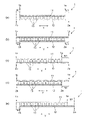
- FIGS. 1(a) to (e) are cross-sectional views schematically showing one embodiment of the absorbent sheet.
- 2(a) to (c) are cross-sectional views schematically showing another embodiment of the absorbent sheet.
- FIGS. 3(a) to 3(f) are plan views schematically showing one embodiment of the absorbent sheet.
- FIG. 4 is a cross-sectional view schematically showing still another embodiment of the absorbent sheet.
- FIG. 5 is a cross-sectional view schematically showing still another embodiment of the absorbent sheet.
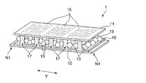
- 6 is a perspective view schematically showing the absorbent sheet shown in FIG. 5.
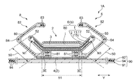
- FIG. FIG. 7 is a cross-sectional view schematically showing one embodiment of an absorbent article provided with an absorbent sheet.
- FIG. 8 is a cross-sectional view schematically showing another embodiment of an absorbent article provided with an absorbent sheet.
- FIG. 9 is a schematic diagram showing an embodiment of a manufacturing apparatus used for manufacturing absorbent sheets.
- the present invention relates to an absorbent sheet with improved liquid absorbency and an absorbent article comprising the sheet.
- the absorbent sheet 1 comprises a first fibrous sheet 11, a second fibrous sheet 12, and particles of a water-absorbing polymer 13 arranged between the fibrous sheets 11,12. Particles of the water-absorbing polymer 13 shown in the figure are arranged in a plurality in the sheet surface direction.
- the first fiber sheet 11 and the second fiber sheet 12 may be the same sheet or different sheets. There are no other members on the outer surfaces of the first fiber sheet 11 and the second fiber sheet 12, but other constituent members such as auxiliary layers are arranged on the outer surfaces of the fiber sheets 11 and 12, as will be described later. not be prevented from being
- the absorbent sheet 1 has a non-overlapping region N1 in which the positions of the peripheral edges of the first fibrous sheet 11 and the positions of the peripheral edges of the second fibrous sheet 12 do not overlap in plan view.
- the non-overlapping region N1 formed in the absorbent sheet 1 may be formed in at least part of the peripheral edge of the absorbent sheet 1 or may be formed in the entire peripheral edge of the absorbent sheet 1 .
- the water absorbing polymer 13 is not arranged in the non-overlapping region N1.
- the geometric shape of the absorbent sheet 1 in plan view may be polygonal such as square, rectangular, quadrilateral, or circular such as perfect circle or ellipse. In the following description, for convenience of description, unless otherwise specified, the absorbent sheet is assumed to have a rectangular plan view shape.
- the cross-sectional dimension of one fiber sheet (the dimension along the horizontal direction Y in the figure) is made larger than the cross-sectional dimension of the other fiber sheet.
- a non-overlapping region N1 is formed on at least one end of the absorbent sheet 1 .
- non-overlapping regions N1 are formed on both side edges of the absorbent sheet 1.
- FIG. 1(c) and 1(d) one side edges 1a and 2a of both fiber sheets 11 and 12 do not overlap, and one side edge of the absorbent sheet 1 has a non-overlapping region N1. formed. The other side edge of the absorbent sheet 1 shown in FIGS.
- both fiber sheets 11 and 12 have the same cross-sectional dimensions, and the two side edges of the fiber sheets 11 and 12 are arranged differently, so that both ends of the absorbent sheet 1 are A non-overlapping region N1 is formed in .
- both sides of the absorbent sheet 1 are open, exposing the water absorbent polymer 13 when viewed from the side of the sheet.
- the second fiber sheet 12 as one fiber sheet is wound so as to cover the side edge 1b of the first fiber sheet 11 as the other fiber sheet.
- One side edge 2b of the second fibrous sheet 12 in the wound position is positioned on the outer surface of the first fibrous sheet 11 .
- the fiber sheets 11, 12 are not bonded together at the wound position.
- a joint 19 is formed where the fiber sheets 11 and 12 are joined together at the position where the second fiber sheet 12 is wound.
- the side edge on the side where the fiber sheet is not wound is open at the side of the absorbent sheet 1, and when viewed from the side of the sheet, The water absorbing polymer 13 is exposed.
- the second fiber sheet 12 is wound so as to cover the side edge 1b of the first fiber sheet 11, the first fiber sheet 11 at the wound position is folded outward. good too.
- the non-overlapping region N1 is formed by winding or bending the fiber sheet, releasing the joining state, and allowing each fiber sheet to have the design dimensions. is determined based on the position of the peripheral edge of the first fiber sheet 11 and the position of the peripheral edge of the second fiber sheet 12 when comparing.
- the fiber sheets 11 and 12 are joined by the joining portion 19 in a state in which one fiber sheet is not wrapped around the other fiber sheet.
- the joint portion 19 may be formed on the entire peripheral edge of the absorbent sheet 1, or may be formed on a part of the peripheral edge. The side edge of the absorbent sheet 1 at the position where the joint 19 is not formed is open, and the water absorbent polymer 13 is exposed when viewed from the side of the sheet.
- the absorbent sheet 1 In order for the absorbent sheet 1 to have the non-overlapping region N1, for example, as shown in FIGS. They can be formed to differ from each other in terms of visual shape or size.
- the fiber sheets may be arranged such that the centroids in plan view are at the same position, or may be arranged at different positions.
- the direction indicated by symbol X is a direction perpendicular to the horizontal direction Y. As shown in FIG.
- All of the absorbent sheets shown in FIGS. 3(a) to 3(f) have a vertical direction X and a horizontal direction Y, and both fiber sheets 11 and 12 have the same length in the vertical direction X.
- the absorbent sheet 1 shown in FIG. 3( a ) includes a first rectangular fiber sheet 11 and a second rectangular fiber sheet 12 having longer short sides than the first fiber sheet 11 .
- the centroids of the fiber sheets 11, 12 are aligned.
- the non-overlapping regions N1 in the present embodiment are formed on both side edges 1a and 1b of the first fiber sheet 11 in the horizontal direction Y, and both side edges in the vertical direction X corresponding to the short sides of the fiber sheets 11 and 12 consistent with each other.
- the length in the longitudinal direction X of both the fiber sheets 11 and 12 and the length in the longitudinal direction X of the absorbent sheet 1 are the same.
- a cross section along the lateral direction Y of this embodiment typically has at least the form shown in FIG.
- the absorbent sheet 1 shown in FIG. 3(b) includes a first rectangular fiber sheet 11 and a second rectangular fiber sheet 12 having shorter sides than the first fiber sheet 11.
- the centroids of the fiber sheets 11, 12 are aligned.
- the non-overlapping regions N1 in the present embodiment are formed on both side edges 2a and 2b of the second fiber sheet 12 in the horizontal direction Y, and both side edges in the vertical direction X corresponding to the short sides of the fiber sheets 11 and 12 consistent with each other. Therefore, in this embodiment, the length in the longitudinal direction X of both the fiber sheets 11 and 12 and the length in the longitudinal direction X of the absorbent sheet 1 are the same.
- a cross section along the lateral direction Y of this embodiment typically has at least the form shown in FIG. 1(b).
- the absorbent sheet 1 shown in FIG. 3( c ) includes a rectangular first fiber sheet 11 and a rectangular second fiber sheet 12 having longer short sides than the first fiber sheet 11 .
- the centroids of each fiber sheet 11, 12 are arranged differently.
- the non-overlapping region N1 in this embodiment is formed outside one side edge 1a of the first fiber sheet 11 in the horizontal direction Y, and the other side edges 1b and 1b of the fiber sheets 11 and 12 2b and both side edges in the longitudinal direction X corresponding to the short sides of the fiber sheets 11 and 12 are aligned with each other. Therefore, in this embodiment, the length in the longitudinal direction X of both the fiber sheets 11 and 12 and the length in the longitudinal direction X of the absorbent sheet 1 are the same.
- a cross section along the horizontal direction Y of this embodiment typically has at least the form shown in FIG. 1(c).
- a cross section along the width direction Y of the absorbent sheet 1 typically has at least the form shown in FIG. 1(d).
- the absorbent sheet 1 shown in FIG. 3( d ) includes a first rectangular fiber sheet 11 and a second rectangular fiber sheet 12 having the same dimensions as the first fiber sheet 11 . That is, the shape and planar view size of one fiber sheet are the same as the shape and planar view size of the other fiber sheet.
- the centroids of each fiber sheet 11, 12 are arranged differently.
- the non-overlapping region N1 in the present embodiment includes both side edges of the absorbent sheet 1 in the lateral direction Y, specifically one side edge 1a of the first fiber sheet 11 in the lateral direction Y, and the second fiber sheet 12. , and both side edges in the longitudinal direction X corresponding to the short sides of the fiber sheets 11 and 12 are aligned with each other. Therefore, in this embodiment, the length in the longitudinal direction X of both the fiber sheets 11 and 12 and the length in the longitudinal direction X of the absorbent sheet 1 are the same.
- each fiber sheet when the plane view shape of each fiber sheet is a rectangle, in plane view, the position of one opposite side of each fiber sheet overlaps, and the other opposite side of each fiber sheet may be arranged so as not to overlap each other to form the non-overlapping region N1 in the absorbent sheet 1, or all sides of the fiber sheets may be arranged so as not to overlap each other in plan view.
- a cross section along the lateral direction Y of this embodiment typically has at least the form shown in FIG.
- the absorbent sheet 1 shown in FIGS. 3(e) and 3(f) comprises a first fiber sheet 11 having a parallelogram shape or a shape whose long sides are a combination of straight lines or curved lines, and a rectangular second fiber sheet 12. and
- the centroids of the fiber sheets 11 and 12 are arranged so as to overlap.
- the non-overlapping region N1 in the present embodiment is formed outside both side edges in the horizontal direction Y of the absorbent sheet 1, and both side edges in the vertical direction X corresponding to the short sides of the fiber sheets 11 and 12 are aligned with each other.
- the length in the longitudinal direction X of both the fiber sheets 11 and 12 and the length in the longitudinal direction X of the absorbent sheet 1 are the same.
- a cross section along the lateral direction Y of this embodiment typically has at least the form shown in FIG.
- one fiber sheet may be wrapped around the other fiber sheet, or a joint 19 may be formed to form the fiber sheet shown in FIGS. may be configured to have the structure shown in
- the absorbent sheet 1 has a rectangular shape in plan view, and one set of sides of two pairs of opposing sides in plan view has More preferably, none of the non-overlapping regions N1 exist, and one or both of the other set of sides have non-overlapping regions N1. It is more preferable that both the fiber sheets 11 and 12 are rectangular, and the directions along the long sides of the fiber sheets 11 and 12 (the X direction in FIG. 3) are aligned with each other. is also more preferred. With such a configuration, the excreted liquid and the water-absorbing polymer are easily brought into contact with each other at the side of the absorbent sheet 1, and the liquid absorbency at the side of the sheet is improved and the liquid absorbency is further improved. An improved absorbent sheet can be obtained.
- the non-overlapping region N1 is preferably formed at the vertical X end and the horizontal Y end, more preferably at the horizontal Y end.
- one fiber sheet is used as the other fiber sheet. It is also preferable that the joint portion 19 is not formed. That is, as shown in FIGS. 1(a) to 1(e), it is preferable that the side of the absorbent sheet 1 is open so that the water-absorbing polymer 13 is exposed when viewed from the side of the sheet. .
- the non-overlapping region N1 is formed by the planar view dimensions of the first fiber sheet 11 and the planar view dimensions of the second fiber sheet 12 being different from each other. If the sheet is a quadrangle such as a rectangle, the length of any side differs by 1 mm or more. If the sheet is circular, the diameter or the major axis or minor axis It means that the length differs by 1 mm or more. Furthermore, as shown in FIG. 3(a) or (b), it is also preferable that the geometric shape of the first fiber sheet 11 in plan view and the geometric shape of the second fiber sheet 12 in plan view are the same. . Having the same geometric shape means, for example, that each fiber sheet has a square, rectangular, or circular shape.
- the geometric shapes are assumed to be the same, and one fiber sheet has a square shape and If the other fiber sheet is rectangular in shape, the geometry is different.
- the water-absorbing polymer can be exposed on the side of the absorbent sheet 1, so that the excreted liquid and the water-absorbing polymer can be easily brought into contact with each other, and the liquid on the side of the sheet can be absorbed. It is possible to obtain an absorbent sheet with improved absorptivity and further improved liquid absorptivity.
- the length of one fiber sheet raw fabric in the width direction is different from the length of the other fiber sheet raw fabric in the width direction. can do.
- the non-polymer region N3 which is the region where the water-absorbent polymer 13 does not exist, is divided into the first fiber sheet 11 and the second fiber sheet. It is preferable to have between 12 and 12.
- the non-polymer region N3 shown in FIG. It is positioned inward of both side edges 1a and 1b.
- the non-polymer region N3 may be formed on the entire peripheral edge of the absorbent sheet 1, or may be formed on a part of the peripheral edge of the absorbent sheet 1, such as one side edge of the absorbent sheet. good too.
- the water-absorbent polymer is exposed at the side of the absorbent sheet, and the liquid absorbency at the side of the sheet can be improved. Since it is possible to efficiently prevent falling-off and movement, an absorbent sheet with further improved liquid absorbency can be obtained.
- the application area may be adjusted so that the adhesive 15 is not applied to the position where the non-polymer area N3 is to be formed.
- the length D1 of the non-overlapping region N1 along the sheet surface direction in the cross-sectional view of the absorbent sheet 1 is the length of the absorbent sheet. 1 mm or more, more preferably 3 mm or more, and still more preferably 1 mm or more, from the viewpoint of achieving both improvement in liquid absorbency and improvement in handleability by preventing the polymer from falling off even when the water-absorbing polymer swells. It is 5 mm or more, preferably 20 mm or less, more preferably 10 mm or less.
- the length D3 of the non-polymer region N3 along the sheet surface direction in the cross-sectional view of the absorbent sheet 1 is the length of the absorbent sheet. 1 mm or more, more preferably 3 mm or more, and still more preferably 1 mm or more, from the viewpoint of achieving both improvement in liquid absorbency and improvement in handleability by preventing the polymer from falling off even when the water-absorbing polymer swells. It is 5 mm or more, preferably 20 mm or less, more preferably 10 mm or less.
- the length D3 is the length between the peripheral edge of the smaller one of the fiber sheets 11 and 12 and the position of the water-absorbing polymer when viewed inward from the peripheral edge.
- the peripheral edge of the absorbent sheet 1 has a portion where the first fiber sheet 11 and the second fiber sheet 12 are not joined to each other.
- the absorbent sheet 1 does not have a joint portion 19 at its peripheral edge, and it is also preferable that it does not have an adhesive 15 which will be described later.
- the portion where the first fibrous sheet 11 and the second fibrous sheet 12 are not bonded to each other may be formed on the entire peripheral edge of the absorbent sheet 1, or may be formed on one side edge of the absorbent sheet, for example. , may be formed on a part of the peripheral edge of the absorbent sheet 1 .
- the end of one fiber sheet is wound so as to cover the end of the other fiber sheet. preferably not.
- the end of one fiber sheet is wound so as to cover the end of the other fiber sheet. preferably not.
- the fiber sheet that constitutes the absorbent sheet is an aggregate of fibers and has a thickness of 5 mm or less measured under a pressure of 1.7 kPa.
- Each fiber sheet is independently preferably inelastic.
- the thickness of the fiber sheet can be measured using, for example, a laser displacement meter.
- the thickness of the fiber sheet measured under a pressure of 1.7 kPa is independently preferably 3 mm or less, more preferably 1 mm or less, still more preferably 0.5 mm, and preferably 0.1 mm. 0.3 mm or more, more preferably 0.3 mm or more.
- the constituent fibers of each of the fiber sheets 11 and 12 include, for example, wood pulp, natural pulp such as cotton and hemp, modified pulp such as mercerized pulp and chemically crosslinked pulp, and resin such as polyethylene and polypropylene.
- Various fibers such as synthetic fibers and fibers obtained by subjecting these fibers to hydrophilic treatment or hydrophobic treatment can be used.
- materials for the fiber sheets 11 and 12 include paper, woven fabric, film, non-woven fabric, and the like.
- Each of the fiber sheets 11 and 12 may independently be a single layer or multiple layers. Further, each of the fiber sheets 11 and 12 may be independently composed of only one fiber assembly (regardless of whether it is a single layer or multiple layers), or may be composed of a first fiber assembly and the assembly.
- Each of the fiber sheets 11 and 12 is preferably a single-layer sheet from the viewpoint of achieving both high levels of liquid absorbency and air permeability.
- the elongation ratio E1 of the first fiber sheet and the elongation ratio E2 of the second fiber sheet are different from each other.
- the elongation ratio E1 of the first fiber sheet 11 is preferably 1.03 times or more, more preferably 1.05 times or more, and preferably 1.20 times or less, more preferably 1.15 times or less.
- the elongation ratio E2 of the second fiber sheet 12 is preferably 1.01 times or more, more preferably 1.02 times or more, and preferably 1.15 times or less, more preferably 1.10 times or less. .
- the fiber sheets 11 and 12 By configuring the fiber sheets 11 and 12 to have different elongation ratios within the range described above, the fiber sheets tend to wrinkle due to the difference in dimensional change between the fiber sheets.
- the side part of 1 becomes easy to open. As a result, it is possible to further improve the liquid absorbability from the sides of the absorbent sheet 1 . It is also preferable that each of the elongation ratios E1 and E2 described above be satisfied when a load of 5 N is applied and elongation is performed in the measurement method described later.
- the extension ratio can be measured as follows. First, an absorbent sheet in a natural state to be measured is cut into a rectangular shape having dimensions of 200 mm in the X direction ⁇ 50 mm in the Y direction. Then, the first fibrous sheet 11 and the second fibrous sheet 12 are peeled off from the cut sheet piece and taken out to obtain a test piece. When each fiber sheet is joined with an adhesive or the like, it is solidified by a method such as blowing cold air from a cold spray, and then carefully taken out so as not to apply excessive external force to the fiber sheet.
- each test piece is stretched in the X direction using a tensile compression tester (Shimadzu Corporation, AG-IS) with a chuck-to-chuck distance of 150 mm at a tensile speed of 300 mm/min so as to elongate the test piece in the X direction.
- the chuck-to-chuck distance is measured under a load of 5 N/50 mm.
- This elongation condition is defined as the maximum elongation condition in the present specification. This measurement is performed 5 times, and the arithmetic average value is taken as the sheet elongation (mm). Then, based on the obtained sheet elongation, the elongation ratio is calculated from the following formula.
- Elongation magnification [times] (sheet elongation [mm]) / (150 [mm])
- the fiber sheets 11 and 12 for example, (i) paper having an elongation ratio E1 of 1.10 times is used as the first fiber sheet, and non-woven fabric having an elongation ratio E2 of 1.03 times is used as the second fiber sheet. (ii) a combination of using paper with an elongation ratio E1 of 1.05 times as the first fiber sheet and a nonwoven fabric with an elongation ratio E2 of 1.01 times as the second fiber sheet, or (iii) the first fiber For example, a nonwoven fabric having an elongation ratio E1 of 1.12 is used as the sheet and a nonwoven fabric having an elongation ratio E2 of 1.03 is used as the second fiber sheet.
- the elongation ratio of each fiber sheet can be adjusted by, for example, using materials with different Young's moduli (e.g., polyethylene, polypropylene, polystyrene, polyurethane, etc.) or changing the length and thickness of the constituent fibers. , Tooth groove processing in which the fiber sheet is caught between the uneven gears and stretched, or by changing the conditions such as hot air and embossing rate, etc. be able to.
- Young's moduli e.g., polyethylene, polypropylene, polystyrene, polyurethane, etc.
- a hydrogel material capable of absorbing and retaining water can generally be used for the water-absorbing polymer 13, and for example, a polymer or copolymer of acrylic acid or an alkali metal salt of acrylic acid can be used. Examples thereof include polyacrylic acid and its salts and polymethacrylic acid and its salts, specifically acrylic acid polymer partial sodium salts.
- the shape of the water-absorbing polymer 13 is not particularly limited, and may be, for example, spherical, tufted, massive, bale-shaped, fibrous, amorphous, or a combination of these particles.
- the basis weight of each of the fiber sheets 11 and 12 constituting the absorbent sheet is preferably 4 g/m 2 or more, more preferably 6 g/m 2 or more, and preferably 100 g/m 2 or less. It is more preferably 50 g/m 2 or less, still more preferably 30 g/m 2 or less.
- the basis weight of the water-absorbent polymer is preferably 60 g/m 2 or more, more preferably 100 g/m 2 or more, and preferably 500 g/m 2 or less, more preferably 400 g/m 2 or less. be.
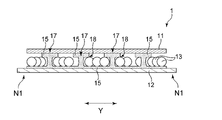
- FIGS. Another embodiment of the absorbent sheet 1 is shown in FIGS.
- the same reference numerals are given to the same members as in the above-described embodiment.
- the absorbent sheet 1 shown in FIGS. 5 and 6 comprises a first fibrous sheet 11, a second fibrous sheet 12, and a plurality of particles of a water-absorbing polymer 13 arranged between the fibrous sheets 11 and 12. .
- the first fiber sheet 11 and the second fiber sheet 12 are bonded together with an adhesive 15 .
- the adhesive 15 shown in FIGS. 5 and 6 is placed on the surfaces of the fiber sheets 11 and 12 facing the water-absorbent polymer 13, respectively.
- the direct bonding sites 17 shown in FIGS. 5 and 6 are formed in the gaps between the particles of the water-absorbing polymer 13 in the region where the water-absorbing polymer 13 is arranged.
- the adhesive 15 when viewed in cross section in the sheet thickness direction, the adhesive 15 forms a columnar shape and directly bonds the two fiber sheets 11 and 12 together.
- the direct bonding sites 17 are formed in a plurality of regular or irregular scattered dots when the absorbent sheet 1 is viewed in the plane direction of the sheet.
- the indirect bonding sites 18 are the site of the first fiber sheet 11 where the adhesive 15 is applied, the site where the water-absorbing polymer 13 is present, and the second fiber sheet 11 .
- the portions of the fiber sheet 12 to which the adhesive 15 is applied are the portions overlapping in the thickness direction.
- the adhesive 15 it is preferable to use one having flexibility that can be stretched according to the swelling change accompanying the liquid absorption of the water-absorbent polymer 13.
- raw materials include (co)polymers of vinyl monomers such as 2-ethylhexyl acrylate, butyl acrylate, ethyl acrylate, cyanoacrylate, vinyl acetate, and methyl methacrylate (ethylene-vinyl acetate copolymers, etc.). ), etc., silicone adhesives containing polydimethylsiloxane polymer, etc., natural rubber adhesives including natural rubber, etc., polyisoprene, chloroprene, etc.
- Isoprene adhesive styrene-butadiene copolymer (SBR), styrene-isoprene-styrene block copolymer (SIS), styrene-butadiene-styrene block copolymer (SBS), styrene-ethylene-butadiene-styrene block copolymer
- SBR styrene-butadiene-styrene block copolymer
- SEPS styrene-ethylene-butadiene-styrene block copolymer
- the adhesive applied to the first fiber sheet 11 , and the adhesive applied to the second fiber sheet 12 may be of the same type or of a different type.
- the fiber sheets 11 and 12 are excellent in flexibility and stretchability, and the state in which the fiber sheets 11 and 12 are directly joined is maintained even after swelling of the water-absorbent polymer, and the shrinkage force is developed to make both the fiber sheets 11 , 12, it is preferable to use a rubber-based adhesive as the adhesive 15, and it is more preferable to use a styrene-based adhesive among the rubber-based adhesives.
- the adhesive 15 is preferably a hot-melt adhesive.
- Hot-melt adhesives include, for example, the various adhesives described above, tackifiers such as petroleum resins and polyterpene resins, plasticizers such as paraffin oils, and, if necessary, phenol-based, amine-based, phosphorus-based, Antioxidants such as benzimidazoles may be included.
- an adhesive 15 is applied to each of the surface of the first fiber sheet 11 facing the water absorbing polymer 13 and the surface of the second fiber sheet 12 facing the water absorbing polymer 13. preferably.
- the adhesive applied to each of the fiber sheets 11 and 12 is bonded together to efficiently form the direct bonding portion 17 on the absorbent sheet 1, and the water absorbent polymer 13 is formed. It is possible to achieve both support at an appropriate position and securing a space in which the water-absorbing polymer 13 can swell.
- the adhesive 15 can easily exist in the gaps between the fibers constituting the fiber sheets 11 and 12, peeling at the interfaces between the fiber sheets 11 and 12 and the adhesive 15 can be prevented. It also has the advantage of being less likely to occur.
- the application area of the adhesive 15 on the second fiber sheet 12 is larger than the application area of the adhesive 15 on the first fiber sheet 11 .
- the water-absorbing polymer 13 is uniformly held on the second fiber sheet 12 having a larger application area of the adhesive 15 than the first fiber sheet 11, and the water-absorbing polymer 13 is
- the liquid permeability from the first fiber sheet 11 side which has a smaller application area of the adhesive 15 than the second fiber sheet 12, can be secured, and the liquid absorption can be further improved.
- the application areas of the two fiber sheets 11 and 12 are compared by laminating the two fiber sheets 11 and 12 having the same shape and area so that no sheet overlaps.
- the application area of the adhesive 15 can be determined, for example, by visualizing the area where the adhesive 15 exists using ink toner or the like on the surfaces of the fiber sheets 11 and 12 on which the adhesive 15 is attached. can be calculated using image processing software or the like. If it is difficult to distinguish, the measurement may be performed after peeling off both sheets using a cold spray or the like.
- the first basis weight of the adhesive 15 applied to the first fiber sheet 11 is the same as that of the adhesive applied to the second fiber sheet 12. A higher than 15 second basis weight is preferred.
- the adhesive 15 applied to the first fiber sheet 11 facilitates the formation of the direct bonding portion 17 with the second fiber sheet 12 , and the second fiber sheet 12 Since the water-absorbing polymer 13 can be held in an appropriate position via the adhesive 15 applied to the surface, the liquid absorption performance can be further improved.
- the first basis weight is preferably 400 g/m 2 or less, more preferably 250 g/m 2 or less, still more preferably 100 g/m 2 or less, and 20 g/m 2 or more is realistic.
- the second basis weight is preferably 30 g/m 2 or less, more preferably 15 g/m 2 or less, still more preferably 10 g/m 2 or less, and more preferably 2 g/m 2 or more.
- the above-described first basis weight and second basis weight are respectively measured and calculated with respect to only the applied portions of the fiber sheets 11 and 12 where the adhesive 15 is applied. Specifically, after separating the fiber sheets 11 and 12 from the absorbent sheet 1, the mass A1 (g) of the first fiber sheet 11 with the adhesive 15 attached thereto is measured. In addition, on the surface of the first fiber sheet 11 on which the adhesive 15 is attached, the portion where the adhesive 15 is present is visualized using ink toner or the like, and in this state, using image processing software, A total area S (m 2 ) of the portion where the adhesive 15 exists is measured. Next, the first fiber sheet 11 is immersed in an organic solvent, and the mass A2 (g) of the fiber sheet after dissolving the adhering adhesive 15 is measured. The first basis weight (g/m 2 ) can be calculated from the formula “(A1 ⁇ A2)/S”. Similarly, the second basis weight (g/m 2 ) can be calculated for the second fiber sheet 12 in the same manner as described above.
- the first fiber sheet 11 is preferably paper from the viewpoint of facilitating the diffusion of liquid in the direction of the sheet surface, further increasing the utilization efficiency of the water-absorbing polymer 13, and realizing high liquid absorbency.
- Paper refers to a product made by agglutinating vegetable fibers such as pulp and other fibers, preferably by a wet process, in accordance with the provisions of JIS P0001.
- the liquid can be easily diffused over a wide area to the periphery of the sheet in the surface direction, and the liquid diffused to the periphery of the sheet is also absorbed from the sides, further improving the liquid absorbency.
- the thickness of the absorbent sheet 1 is preferably 0.3 mm or more, more preferably 0.6 mm or more, from the viewpoint of improving liquid absorption.
- the thickness of the absorbent sheet is preferably 4 mm or less, more preferably 3 mm or less, and still more preferably 2 mm. It is below.
- the thickness of the absorbent sheet described above is the thickness of the entire absorbent sheet measured under a pressure of 1.7 kPa.
- the absorbent sheet 1 having the above configuration has a non-overlapping region N1 in which the positions of the peripheral edges of the first fibrous sheet 11 and the positions of the peripheral edges of the second fibrous sheet 12 do not overlap.
- the excreted liquid that has diffused into the absorbent sheet 1 moves to the side of the absorbent sheet 1, the excreted liquid can be brought into direct contact with the water-absorbing polymer positioned on the side.
- the absorbent sheet 1 of the embodiment described above may be used as it is.
- one absorbent sheet 1 may be used, or a plurality of absorbent sheets may be used in a laminated state.
- absorbent sheets 1 of the same or different embodiments may be used in combination.
- the absorbent sheet 1 of each embodiment described above can be used as a constituent member of an absorbent article.
- an absorbent article has a longitudinal direction along the wearer's front-rear direction and a width direction orthogonal to the longitudinal direction, and has a surface sheet positioned on the skin-facing side and a non-skin-facing side. It can be used in a state in which the absorbent sheet of the present invention is arranged between the top sheet and the back sheet.
- the absorbent sheet constitutes part of the absorbent body in the absorbent article.
- absorbent articles include incontinence pads, sanitary napkins, disposable diapers, and the like, preferably disposable diapers.
- Absorbent articles typically have a ventral region located on the ventral side of the wearer when worn, a dorsal region located on the dorsal side of the wearer, and a crotch region located between the ventral region and the dorsal region. area and have.
- the abdominal region, the crotch region, and the back region virtually divide the entire longitudinal length of the absorbent article into three equal parts, and extend continuously along the front-rear direction of the wearer.
- the crotch region has an excretory part facing portion that is arranged to face the excretory part of the wearer when the absorbent article is worn.
- the term “skin-facing surface” refers to a surface of an absorbent article or its constituent members (for example, an absorbent body described later) that faces the wearer's skin when the absorbent article is worn.
- the "non-skin facing surface” is the side of the absorbent article or its constituent members opposite to the skin side when the absorbent article is worn, that is, the side relatively far from the wearer's skin. This is the side you are facing.
- the term "when worn” as used herein means a state in which the absorbent article is maintained in a normal and appropriate wearing position, that is, in a correct wearing position of the absorbent article.
- topsheet and backsheet used in absorbent articles those conventionally used in absorbent articles can be used without any particular restrictions.
- the surface sheet for example, various liquid-permeable nonwoven fabrics, perforated films, and the like can be used.
- back sheet a liquid-impermeable or water-repellent resin film, a laminate of a resin film and a non-woven fabric, or the like can be used.
- An absorbent body typically includes an absorbent core and a core wrap sheet covering the absorbent core.
- the absorbent core comprises, for example, a pile of water-absorbent natural fibers such as pulp fibers, a mixed pile containing water-absorbent natural fibers and a water-absorbent polymer, and/or at least one of the absorbent sheets 1 described above. composed of When the absorbent core includes both the stack and the absorbent sheet, the sizes in plan view may be the same or different.
- the core wrap sheet is made of tissue paper or water-permeable nonwoven fabric. The core wrap sheet covers at least the skin-facing side of the absorbent core, and preferably covers the entire skin-facing side and non-skin-facing side of the absorbent core.
- leakage-preventing cuffs extending in the longitudinal direction are arranged on both sides along the longitudinal direction on the side facing the skin, depending on the specific use of the absorbent article. is also preferred.
- a leak-tight cuff generally has a proximal end and a free end.
- the leak-proof cuff has a base end on the skin-facing side of the absorbent article and stands up from the skin-facing side.
- the leak-tight cuff is constructed from a liquid-resistant or water-repellent and breathable material.
- An elastic member made of rubber thread or the like may be arranged in a stretched state at or near the free end of the leak-proof cuff.
- the contraction of the elastic member causes the leakage-preventing cuff to stand up toward the wearer's body, and the liquid excreted on the topsheet flows along the topsheet and becomes absorbent. Leakage to the outside in the width direction of the article is effectively prevented.
- FIGS. 7 and 8 schematically show cross-sectional views of an embodiment of an absorbent article 1A including the absorbent sheet 1.
- FIG. The width direction of the absorbent article 1A is indicated by symbol Y and is the same as the lateral direction Y in FIGS.
- An absorbent article 1A shown in FIGS. 7 and 8 includes an absorbent body 2 having a topsheet 3, a backsheet 4 and an absorbent body 5, and a pair of leak-proof cuffs 8.
- the absorbent article 1A shown in FIGS. 7 and 8 includes an outer body 90 arranged on the non-skin facing side of the absorbent body 2, and the absorbent body 2 and the outer body 90 are are joined with an adhesive or the like via a leak-proof cuff 8 .
- the absorbent main body 2 typically has a rectangular shape in plan view, and is arranged in the center of the outer packaging 90 in the width direction Y with its longitudinal direction aligned with the longitudinal direction of the absorbent article 1A. It extends longitudinally across the side region, the crotch region and the back region.
- the core wrap sheet covering the outer surface of the absorbent body 5 is not shown, but the outer surface of the absorbent body 5 in this embodiment is preferably covered with a core wrap sheet.
- the topsheet 3 shown in FIGS. 7 and 8 traverses the skin-facing side of the absorbent body 5 in the width direction Y and is wrapped around the non-skin-facing side of the absorbent body 5 .
- the surface sheet 3 has a size capable of covering the entire skin-facing surface of the absorbent body 5, and covers the entire skin-facing surface of the absorbent body 5 and both side edges in the width direction Y of the absorbent body 5.
- the non-skin-facing surface of the absorbent body 5 is covered with a predetermined range inward in the width direction Y from the both side edges.
- the pair of extending portions 3E, 3E of the top sheet 3 are provided between the absorber 5 and the sheet 80 for forming the leak-preventive cuff, which will be described later, at the fixing portions 81 of the leak-preventive cuff 8, which will be described later. is fixed to
- the surface sheet 3 does not cover the entire non-skin-facing surface of the absorbent body 5, but covers the central portion of the non-skin-facing surface of the absorbent body 5 in the width direction Y (the portion located between the pair of fixing portions 81, 81). ) is not covered with the top sheet 3 .
- each leak-proof cuff 8 includes a leak-proof cuff-forming sheet 80 that is liquid-resistant or water-repellent and breathable. It contains a layered part.
- Each leak-preventing cuff 8 (leak-preventing cuff-forming sheet 80) is arranged continuously along the side portion along the longitudinal direction of the absorbent main body 2 over substantially the entire length in the longitudinal direction of the absorbent main body 2 .
- any material that is used as a material for leakage-preventing cuffs in this type of absorbent article can be used without particular limitation.
- a laminated material or the like of a nonwoven fabric or the like can be used.
- the leak-proof cuff 8 has a fixed portion 81 in which a sheet 80 for forming a leak-proof cuff is fixed to another member, and an upright portion 82 in which the sheet 80 stands up on the wearer's side.
- the standing portion 82 is a portion of the leak-proof cuff-forming sheet 80 that is not fixed to other members, and includes a free end.
- the standing portion 82 exists at least in the crotch region.
- the fixed part 81 is a part that constitutes a fixed end when the standing part 82 stands up toward the wearer's skin when the absorbent article is worn. It is a portion that is joined to other members, specifically the absorbent main body 2 and/or the exterior body 90, by a known fixing method such as an adhesive or heat fusion.
- the leakage-preventing cuff-forming sheet 80 and/or the outer body 90 constitute non-skin-side members adjacent to each other on the non-skin facing surface of the absorbent main body 2 .
- the fixing portion 81 extends continuously or discontinuously in the longitudinal direction over substantially the entire length of the leak-proof cuff forming sheet 80 .
- the upright portion 82 has a portion that is stretchable in the longitudinal direction.
- a first leak-prevention cuff-forming elastic member 83 is longitudinally attached to the free end of the standing portion 82 (the portion of the standing portion 82 that comes closest to the wearer's skin when the standing portion 82 is standing).
- a second leak-prevention cuff-forming elastic member 84 is arranged to extend in the longitudinal direction at an intermediate position between the free end of the upright portion 82 and the fixed portion 81 . It is Each of the elastic members 83 and 84 is joined in a stretched state between the leak-proof cuff-forming sheets 80 and 80 forming a two-layer structure by a fixing method such as an adhesive.
- the standing portion 82 has stretchability in the longitudinal direction at the fixed portions of the elastic members 83 and 84 .
- the number of elastic members 83 and 84 is not particularly limited, and may be one or more independently.
- the second leakage-preventing cuff-forming elastic member 84 (an elastic member arranged at an intermediate position between the free end of the standing portion 82 and the fixed portion 81) may not be provided.
- the erecting portion 82 erects the fixing portion 81, its vicinity, or the width direction end portion of the auxiliary layer 60, which will be described later, by the contractile force of the leak-proof cuff-forming elastic members 83 and 84. It stands up toward the wearer's skin side as a base end. In such an upright state of the leakage-preventing cuff 8, the upright upright portion 82 prevents bodily fluids such as urine excreted by the wearer from moving outward in the width direction Y. Together with the damming effect of the body fluid by the pair of upright portions 50, 50 on both sides in the direction Y, lateral leakage is effectively suppressed.
- the entire absorbent article 1A in the upright state of the leak-preventing cuff 8, the entire absorbent article 1A is moved to the central portion in the longitudinal direction of the absorbent main body 2 by the contractile force of the leak-preventing cuff-forming elastic members 83 and 84. is curved and deformed so as to be convex toward the non-skin facing side (back sheet 4 side), the absorbent article 1A can easily fit the shape of the wearer's body.
- erection inhibiting portions which are portions where the sheet 80 for forming the leak-proof cuff is inhibited from standing up, are typically formed.
- the erection-inhibiting portions are formed in the ventral region and the dorsal region, and an erecting portion 82 is formed in a portion sandwiched between the erection-inhibiting portions in the longitudinal direction.
- the standing-up inhibiting portion is formed by fixing the leak-prevention cuff-forming sheet 80 to the skin-facing surface (topsheet 3) of the absorbent body 2 .
- the absorbent bodies 5 are positioned at least in the crotch region on both sides in the width direction across the central part of the absorbent body 5 in the width direction Y, and are configured to be able to stand up toward the skin side of the wearer when worn. It has standing portions 50 , 50 and a non-standing portion 51 located in the central region in the width direction Y and sandwiched between the pair of standing portions 50 , 50 .
- the absorbent core 6 has a laminated structure of an auxiliary layer 60 positioned on the skin facing side (top sheet 3 side) and an absorbent sheet 1 positioned on the non-skin facing side (back sheet 4 side).
- the auxiliary layer 60 may be arranged on the non-skin facing side of the absorbent sheet 1 . That is, the auxiliary layer 60 is arranged on at least one of the skin-facing surface and the non-skin-facing surface of the absorbent sheet 1 , preferably on the skin-facing surface of the absorbent sheet 1 .
- the non-upright portion 51 of the absorbent body 5 preferably has a multi-layer structure.
- the absorbent core 6 constituting the non-upright portion 51 is composed of an auxiliary layer 60 located on the skin-facing surface side (topsheet 3 side) and a non-skin-facing surface side (backsheet 4 side). It has a laminated structure with the absorbent sheet 1 located at .
- at least the absorbent sheet 1 exists in the pair of standing portions 50 , 50 .
- the auxiliary layer 60 is made of, for example, a laminate of at least one of synthetic fibers and water-absorbent natural fibers, or a mixed laminate of at least one of synthetic fibers and water-absorbent natural fibers and particles of absorbent polymer. Configured.
- the auxiliary layer 60 in the absorbent article 1A is preferably a mixed fiber stack containing water-absorbent natural fibers such as fluff pulp and a water-absorbent polymer in order to increase the liquid absorption capacity of the absorbent body 5 .
- the absorbent core 6 in the pair of standing portions 50, 50 which are portions that can stand up toward the skin of the wearer, does not have the auxiliary layer 60 and is composed only of the absorbent sheet 1. It is That is, the length in the width direction Y of the auxiliary layer 60 constituting the absorbent article 1A is shorter than the length in the width direction Y of the absorbent sheet 1, and the pair of standing portions 50, 50 are formed. preferably. Both the length in the width direction Y of the auxiliary layer 60 and the length in the width direction Y of the absorbent sheet 1 are compared at the position where the length in the width direction Y is the shortest.
- the upright portion 50 can be formed thin while enhancing the liquid absorbency, so that the feeling of wearing the absorbent article is improved and the fit of the absorbent article to the wearer is improved. It can be improved further.
- the liquid absorption amount and the absorption speed of the non-upright portion 51 are improved, and the diffusion of the liquid in the thickness direction is suppressed, so that side leakage can be prevented more reliably.
- a pair of side elastic members 52 for raising the standing portion 50 are arranged at or near both side edges along the longitudinal direction of the absorbent body 5 .
- the side elastic members 52 are arranged in a longitudinally stretched state between the absorbent body 5 and the topsheet 3 .
- the side elastic members 52 are fixed in a stretched state to at least the absorbent body 5 and further to the topsheet 3 by a known fixing method such as an adhesive.
- the side elastic member 52 is arranged at least in the crotch region, and may be one as shown in the figure, or may be plural.
- both sides in the width direction Y of the absorbent body 5 which are portions that can be erected by contraction of the side elastic members 52, are formed as a pair of standing portions 50, 50 to prevent leakage as the absorbent main body 2 and the non-skin side member.
- the fixing portion 81 that is the joint position with the cuff-forming sheet 80 and/or the outer body 90, it stands up toward the wearer's skin side. At this time, in a cross-sectional view along the width direction Y shown in FIG.
- the absorbent body 5 has a non-upright portion 51 as a bottom portion, and a pair of upright portions 50, 50 extending obliquely from the bottom portion toward the wearer's skin side.
- the sides are shaped like a tray.
- a gap capable of absorbing liquid is formed between the standing portion 50 and the leak-proof cuff 8 .
- the side elastic members 52 may be arranged inside the absorbent body 5 .
- the side elastic members 52 are arranged in a longitudinally stretched state between the absorbent core 6 and the core wrap sheet at or near both side edges along the longitudinal direction of the absorbent body 5.
- the side elastic members 52 may be fixed to one or both of the absorbent core 6 and the core wrap sheet by a known fixing method such as an adhesive.
- various known elastic materials that are commonly used in absorbent articles of this type can be used without particular limitation, such as styrene-butadiene and butadiene. , synthetic rubber such as isoprene and neoprene, natural rubber, EVA, elastic polyolefin, and polyurethane.
- a thread-like (string rubber, etc.) or band-like (flat rubber, etc.) having a rectangular, square, circular, polygonal cross section, etc., or a multi-filament type thread-like one can be preferably used. .
- the exterior body 90 is arranged at a position relatively far from the absorbent body 5 and is arranged at a position relatively close to the outer layer sheet 91 forming the outer surface of the absorbent article 1A and the absorbent body 5, and is arranged at a position relatively close to the absorbent article 1A. and an inner layer sheet 92 forming an inner surface.
- the two sheets 91 and 92 are bonded together and integrated by a bonding method such as an adhesive.
- One or a plurality of elastic members 94 are arranged in a stretched state between the outer layer sheet 91 and the inner layer sheet 92 that constitute the outer body 90. When the absorbent article is worn, the elastic members 94 contract to Leg gathers are formed around the legs of the wearer.
- Both the sheets 91 and 92 forming the exterior body 90 may be sheets of the same type or may be sheets of different types. Each of the sheets 91 and 92 may have stretchability, particularly stretchability in the width direction Y.
- nonwoven fabrics produced by various methods can be used. Specifically, for example, single-layer nonwoven fabrics such as air-through nonwoven fabrics, heat roll nonwoven fabrics, spunlace nonwoven fabrics, spunbond nonwoven fabrics, meltblown nonwoven fabrics, etc. Laminated nonwoven fabrics having two or more layers can be mentioned.
- the sheets 91 and 92 may be composite sheets in which these nonwoven fabrics and films are laminated together.
- the first fiber sheet 11 in the absorbent sheet 1 is arranged so as to be the liquid receiving surface, which is the surface with which the sheet first contacts liquid. is preferred. That is, it is preferable to arrange the absorbent sheet 1 so that the first fiber sheet 11 is arranged on the side facing the skin.
- the absorbent sheet 1 arranged in the absorbent article has a rectangular shape in plan view, and one of the two pairs of opposing sides of the sheet 1 has no non-overlapping region N1 on one pair of sides. , the other set of sides more preferably have non-overlapping regions on one or both of them.
- the absorbent sheet can be arranged such that one pair of sides of the absorbent sheet 1 that does not have the non-overlapping region N1 is positioned at both longitudinal end edges of the absorbent core 6 in the absorbent article. preferable.
- the other pair of sides having the non-overlapping region N1 of the absorbent sheet 1 are arranged so as to be positioned at both edges of the absorbent core 6 in the width direction.
- the absorbent sheet 1 in the absorbent article has a width along the width direction Y of the first fiber sheet 11 that is shorter than a width along the width direction Y of the second fiber sheet 12.
- the non-overlapping regions N1 of the absorbent sheet 1 shown in FIG. With such a configuration, the excreted liquid excreted on the skin-facing surface is diffused in the surface direction of the surface sheet and reaches the side portion of the absorbent sheet 1, and is easily absorbed directly by the water-absorbing polymer.
- the second fiber sheet 12 having a large width along the width direction Y makes it easier for the liquid to be indirectly absorbed by the water-absorbing polymer. As a result, liquid absorbability is further improved.
- the absorbent sheet 1 in the absorbent article has a width along the width direction Y of the first fiber sheet 11 larger than a width along the width direction Y of the second fiber sheet 12. It is preferable to arrange the absorbent sheet 1 so that the first fiber sheet 11 is arranged on the skin-facing side of the absorbent article in a long state.
- FIG. 9 shows an embodiment of a manufacturing apparatus 100 suitable for use in this manufacturing method.
- This manufacturing method is suitable for manufacturing an absorbent sheet 1 in which both fiber sheets 11 and 12 are bonded to each other with an adhesive 15 .
- a manufacturing apparatus 100 shown in FIG. 9 includes a first roll 110 and a second roll 120 .
- the first raw fabric roll 110 lets out the long band-shaped first fiber sheet 11 along the conveying direction R and can supply it to the first adhesive application section 130 described later.
- the second raw fabric roll 120 lets out the long band-shaped second fiber sheet 12 along the transport direction R and supplies it to the second adhesive application section 140 described later.
- the manufacturing apparatus 100 includes a first adhesive application section 130 and a second adhesive application section 140 .
- the first adhesive application section 130 can continuously or intermittently apply the adhesive 15 to one surface of the first fiber sheet 11 supplied from the first material roll 110 .
- the first adhesive application portion 130 shown in the figure is configured to apply the adhesive 15 intermittently.
- the second adhesive application section 140 can continuously or intermittently apply the adhesive 15 to one surface of the second fiber sheet 12 supplied from the second material roll 120 .
- the second adhesive application portion 140 shown in the figure is configured to apply the adhesive 15 continuously.
- FIG. 9 shows a state in which the adhesive 15 applied to the first fiber sheet 11 and the adhesive 15 applied to the second fiber sheet 12 are both of the same type. However, different types of adhesives may be used.
- the manufacturing apparatus 100 includes a polymer spraying section 150.
- the polymer spraying section 150 is located above the second fiber sheet 12 and is capable of spraying the water-absorbent polymer 13 on the surface of the second fiber sheet 12 to which the adhesive 15 is applied.
- the manufacturing apparatus 100 preferably further includes a press roll 160.
- the press roll 160 presses a laminate obtained by superimposing the first fiber sheet 11 on the second fiber sheet 12 containing the water-absorbing polymer 13 via the guide roll 161 .
- the press rolls 160 in this embodiment are arranged in pairs, and preferably each roll has a smooth peripheral surface. As a result, it is possible to form a long band-shaped absorbent sheet 1 in which many direct bonding portions 17 are formed.
- the manufacturing apparatus 100 may include a sheet cutting section downstream of the press roll 160 (not shown).
- the sheet cutting section cuts the long band-shaped absorbent sheet 1 at a predetermined position to form an absorbent sheet 1 having a predetermined size.
- a cutter roll having a cutter blade extending along a direction orthogonal to the conveying direction R can be used.
- a method of manufacturing an absorbent sheet using the manufacturing apparatus 100 having the above configuration is as follows. First, the adhesive 15 is applied to at least one of the two fiber sheets 11 and 12, preferably to one surface of the first fiber sheet 11 and one surface of the second fiber sheet 12. .
- the adhesive 15 supplied from the first adhesive application unit 130 is applied to one surface of the first fiber sheet 11 while the fiber sheet is being conveyed. Further, while the fiber sheet is conveyed, the adhesive 15 supplied from the second adhesive application section 140 is applied to one surface of the second fiber sheet 12 .
- the adhesive 15 may be applied to one fiber sheet and then to the other fiber sheet, or may be applied to the fiber sheets 11 and 12 at the same time. When the adhesive 15 is applied to only one of the fiber sheets 11 and 12, the adhesive 15 is supplied from either the first adhesive application section 130 or the second adhesive application section 140. Just apply it.
- the width direction length of the first fibrous sheet 11 supplied from the first fabric roll 110 and the length of the second fabric are adhered in a state in which the widthwise central portions of the respective sheets are aligned by making the length in the width direction of the original fabric of the second fiber sheet 12 supplied from the roll 120 different, or Alternatively, the two fiber sheets 11 and 12 can be adhered in a state in which one side portion along the conveying direction of the two original fabrics is overlapped.
- the length in the width direction of the first fiber sheet 11 supplied from the first roll 110 and the length in the width direction of the second fiber sheet 12 supplied from the second roll 120 may be adhered in a state in which they are transported so that the widthwise central portions of the sheets do not coincide with each other.
- the method of applying the adhesive 15 in the first adhesive applying portion 130 is Preferably, it is a method that can be adjusted to increase the basis weight of the adhesive 15 in the applied portion, and in detail, the non-applied portion of the adhesive 15 is formed, such as spiral coating, summit coating, omega coating, etc. It is preferable to employ a pattern coating method.
- the coating method in the second adhesive coating unit 140 is preferably a method capable of continuously coating the adhesive 15 with a low basis weight. Specifically, spray coating or coater coating is adopted. is preferred, and it is more preferred to employ coater coating.
- the basis weight applied to each of the fiber sheets 11 and 12 may be adjusted so as to fall within the range described above.
- the water-absorbing polymer 13 is sprayed from the polymer spraying section 150 on the surface of the second fiber sheet 12 to which the adhesive 15 is applied.
- the water-absorbing polymer 13 is adhered to and carried by the adhesive 15 on the second fiber sheet 12 .
- the water-absorbing polymer 13 is evenly dispersed in the surface direction of the second fiber sheet 12 .
- the amount of the water-absorbing polymer 13 sprayed in the surface direction of the second fiber sheet 12 may be changed according to the intended absorbent sheet 1.
- the length of the original fabric in the width direction (the direction perpendicular to the transport direction R at the time of production) is smaller than the length of the original fabric. It can be formed by adjusting the application area of the adhesive 15 and applying it to the raw fabric, and then spraying the water absorbing polymer 13 .
- the fiber sheets 11 and 12 are overlapped so that the adhesive coated surfaces of the fiber sheets 11 and 12 face each other.
- a laminate obtained by stacking the fiber sheets 11 and 12 has the absorbent polymer 13 disposed between the fiber sheets 11 and 12 . If necessary, this laminate may be directly supplied to the sheet cutting section without being introduced into the press roll 160 to obtain the intended absorbent sheet. Alternatively, both the fiber sheets 11 and 12 may be directly introduced between the press rolls 160 and pressed while being overlapped without being overlapped in advance.
- the fiber sheets 11 and 12 that have been superimposed are introduced between a pair of press rolls 160 and pressed.
- the adhesive 15 applied to the fiber sheets 11 and 12 can be easily bonded directly, so that the direct bonding portion 17 can be easily formed.
- the adhesiveness between the water absorbing polymer 13 and the adhesive 15 can be enhanced. As a result, it is possible to improve both the liquid absorbency and the retention of the water-absorbing polymer.
- the fiber sheets 11 and 12 are compared using a relatively soft press roll 160 whose surface is made of an elastic material or the like. It is preferable to press with a relatively high pressure. By pressing the fiber sheets 11 and 12 under such conditions, the peripheral surfaces of the press rolls can follow the unevenness of the fiber sheets 11 and 12 caused by the water-absorbing polymer 13, so that the fiber sheets 11 can be pressed against each other. , 12 can be effectively pressurized to facilitate direct bonding.
- the material of the press roll 160 for example, an elastic material such as hard rubber, silicone rubber, or silicone sponge can be used. preferable.
- the pressure applied by the press roll is , expressed as linear pressure, is preferably 2500 N/m or more, more preferably 3500 N/m or more, preferably 6500 N/m or more, more preferably 5500 N/m or more. This pressure is higher than the roll-to-roll pressing conditions normally employed.
- the sheet cutting section cuts the long strip-shaped absorbent sheet 1 into a predetermined size to obtain an absorbent sheet.
- the absorbent sheet 1 thus formed has a square or rectangular shape in plan view, and at least non-overlapping regions N1 are formed on one opposite side corresponding to both sides along the conveying direction of the original fabric. be.
- the adhesive 15 in order to form the non-overlapping regions N1 at positions corresponding to both sides along the direction orthogonal to the conveying direction of the original sheet, the adhesive 15 must be applied to the positions to be cut by the sheet cutting section. What is necessary is just not to hold
- the absorbent sheet 1 When the absorbent sheet 1 is manufactured without using the adhesive 15, it can be manufactured, for example, by the method described in FIG. 3 of JP-A-8-246395. Specifically, one of the fiber sheets is made by wet papermaking or the like, and the water-absorbing polymer 13 is sprayed on the fiber sheet in a wet state to develop the stickiness of the water-absorbing polymer 13 due to water absorption, Fix to the fiber sheet. Thereafter, the other fiber sheet is superimposed on the surface on which the water-absorbing polymer 13 has been sprayed to form a laminate, and the laminate is dried by a known drying method such as a Yankee dryer.
- the water absorbent polymer 13 is sprayed on one of the fiber sheets, water is further sprayed, and the water absorbent polymer 13 sticks. The properties are expressed and fixed to the fiber sheet. Thereafter, the other fiber sheet is superimposed on the surface on which the water-absorbing polymer 13 has been sprayed to form a laminate, and the laminate can be dried by the drying method described above.
- the absorbent sheet of the present invention is manufactured through the above steps.
- This absorbent sheet has high levels of liquid diffusibility and breathability in addition to high liquid absorbency.
- the water-absorbing polymer can be sufficiently swollen while being fixed at a predetermined position, so that high liquid-absorbing performance can be effectively exhibited.
- ⁇ 1> comprising a first fibrous sheet, a second fibrous sheet, and particles of a water-absorbing polymer disposed between the fibrous sheets;
- An absorbent sheet having a non-overlapping region in which the positions of the peripheral edges of the first fibrous sheet and the positions of the peripheral edges of the second fibrous sheet do not overlap in plan view.
- ⁇ 2> The absorbent sheet according to ⁇ 1> above, wherein the non-overlapping region is formed by the planar view dimensions of the first fiber sheet and the planar view dimensions of the second fiber sheet being different.
- ⁇ 3> ⁇ 1> or ⁇ 2> above, wherein there is a region where the water-absorbent polymer does not exist between the first fiber sheet and the second fiber sheet when viewed inward from the peripheral edge of the absorbent sheet. absorbent sheet.
- ⁇ 4> The absorbent sheet according to ⁇ 3>, wherein the region where the water-absorbent polymer does not exist is located inside the non-overlapping region.
- the planar view dimension of the first fiber sheet is smaller than the planar view dimension of the second fiber sheet
- the length of the region in which the water-absorbent polymer does not exist along the sheet surface direction in a cross-sectional view of the absorbent sheet is preferably 1 mm or more, more preferably 3 mm or more, still more preferably 5 mm or more, and preferably 20 mm or less.
- ⁇ 9> The absorbent sheet according to any one of ⁇ 1> to ⁇ 8>, wherein the peripheral edge of the absorbent sheet has a portion where the first fiber sheet and the second fiber sheet are not bonded to each other.
- ⁇ 10> The absorbent according to any one of ⁇ 1> to ⁇ 9> above, wherein the end of one fiber sheet is wrapped around the periphery of the absorbent sheet so as to cover the end of the other fiber sheet. sheet.
- ⁇ 11> The absorbent according to any one of ⁇ 1> to ⁇ 9>, wherein the edge of one of the fiber sheets is not wrapped around the edge of the absorbent sheet so as to cover the edge of the other fiber sheet. sheet.
- ⁇ 12> Any one of ⁇ 1> to ⁇ 11> above, wherein the stretching ratio of the first fiber sheet is different from the stretching ratio of the second fiber sheet when the fiber sheets are stretched by applying the same load.
- the absorbent sheet described in . ⁇ 13> The elongation ratio when the first fiber sheet is stretched with a load of 5 N and the elongation ratio when the second fiber sheet is stretched with a load of 5 N are different from each other.
- the elongation ratio of the first fiber sheet is preferably 1.03 times or more, more preferably 1.05 times or more, and preferably 1.20 times or less, more preferably 1.15 times or less
- the elongation ratio of the second fiber sheet is preferably 1.01 times or more, more preferably 1.02 times or more, and preferably 1.15 times or less, more preferably 1.10 times or less. 13> the absorbent sheet.
- the absorbent sheet has a rectangular shape in plan view, and in plan view, of two sets of opposing sides, none of the non-overlapping regions exist on one set of sides, and the other set of sides does not have the non-overlapping region.
- Both the first fiber sheet and the second fiber sheet are rectangular, The first fiber sheet and the second fiber sheet according to any one of ⁇ 1> to ⁇ 15>, wherein the directions along the long sides of both the fiber sheets are aligned with each other. absorbent sheet.
- the length of the non-overlapping region along the sheet surface direction in cross-sectional view of the absorbent sheet is preferably 1 mm or more, more preferably 3 mm or more, still more preferably 5 mm or more, and preferably 20 mm or less, more preferably 10 mm.
- the basis weights of the first fiber sheet and the second fiber sheet constituting the absorbent sheet are each independently preferably 4 g/m 2 or more, more preferably 6 g/m 2 or more, and preferably 100 g. /m 2 or less, more preferably 50 g/m 2 or less, still more preferably 30 g/m 2 or less, the absorbent sheet according to any one of ⁇ 1> to ⁇ 17>.
- the basis weight of the water-absorbing polymer is preferably 60 g/m 2 or more, more preferably 100 g/m 2 or more, and preferably 500 g/m 2 or less, more preferably 400 g/m 2 or less.
- the first fibrous sheet and the second fibrous sheet are directly bonded by the adhesive without passing through the water-absorbing polymer, and are bonded by the adhesive through the water-absorbing polymer.
- ⁇ 22> The absorbent sheet according to ⁇ 20> or ⁇ 21>, wherein a rubber-based adhesive is used as the adhesive.
- ⁇ 23> The absorbent sheet according to ⁇ 22> above, wherein the rubber-based adhesive is a styrene-based adhesive.
- ⁇ 24> The absorbent sheet according to any one of ⁇ 20> to ⁇ 23>, wherein the adhesive is a hot melt adhesive.
- the basis weight of the adhesive applied to the first fiber sheet is preferably 400 g/m 2 or less, more preferably 250 g/m 2 or less, still more preferably 100 g/m 2 or less, and 20 g/m 2 or more.
- the basis weight of the adhesive applied to the second fiber sheet is preferably 30 g/m 2 or less, more preferably 15 g/m 2 or less, still more preferably 10 g/m 2 or less, and 2 g/m 2 or more.
- the thickness of the absorbent sheet is preferably 0.3 mm or more, more preferably 0.6 mm or more, preferably 4 mm or less, more preferably 3 mm or less, and still more preferably 2 mm or less. 29>.
- a top sheet having a longitudinal direction corresponding to the front-rear direction of the wearer and a width direction perpendicular to the longitudinal direction, the top sheet being arranged on the skin-facing side, the back sheet being arranged on the non-skin-facing side, and both of these.
- An absorbent article comprising an absorbent body comprising an absorbent body disposed between sheets, An absorbent article further comprising the absorbent sheet according to any one of ⁇ 1> to ⁇ 30> as the absorbent body.
- the absorbent body further comprises an auxiliary layer disposed on at least one of the skin-facing surface and the non-skin-facing surface of the absorbent sheet, The absorbent article according to ⁇ 31>, wherein the length of the auxiliary layer in the width direction is shorter than the length of the absorbent sheet in the width direction.
- the absorbent main body is joined to a non-skin-side member disposed on the non-skin facing side of the absorbent main body, Thread-like or band-like elastic members are arranged so as to extend in the longitudinal direction on both side regions of the absorbent body in the width direction, By contraction of each of the elastic members, both sides in the width direction of the absorbent body can be raised starting from the joint position between the absorbent body and the non-skin side member, and
- ⁇ 34> The absorbent article according to any one of ⁇ 31> to ⁇ 33>, wherein the absorbent sheet is arranged such that the first fiber sheet is arranged on the side facing the skin.
- the absorbent sheet is rectangular in plan view, Of the two sets of sides facing each other of the absorbent sheet, none of the non-overlapping regions exist on one set of sides, and the non-overlapping regions exist on one or both of the other set of sides.
- the absorbent body has an absorbent core
- the absorbent sheet is arranged such that one set of sides of the absorbent sheet that does not have the non-overlapping region is positioned at both longitudinal ends of the absorbent core in the absorbent article.
- ⁇ 37> The absorbent article according to ⁇ 36> above, wherein the other pair of sides of the absorbent sheet having the non-overlapping regions are positioned at both widthwise edges of the absorbent core.
- ⁇ 38> applying an adhesive to at least one of the first fiber sheet and the second fiber sheet; Sprinkling a water-absorbent polymer on the surface of the fiber sheet to which the adhesive is applied, The length of the first fibrous sheet in one direction and the length of the second fibrous sheet in one direction are different, and the water-absorbing polymer is disposed between the two fibrous sheets.
- Each fiber sheet is superimposed, Pressing the superimposed fiber sheets, and then A method for manufacturing an absorbent sheet, wherein each of the pressed fiber sheets is cut.
- ⁇ 39> The manufacturing method according to ⁇ 38> above, wherein a pair of press rolls are used to press the stacked fiber sheets between the press rolls.
- ⁇ 40> The manufacturing method according to ⁇ 39> above, wherein a press roll having a surface made of an elastic material is used as the press roll to press each fiber sheet.
- ⁇ 41> The manufacturing method according to any one of ⁇ 38> to ⁇ 40>, wherein the adhesive is applied to one surface of the first fiber sheet and one surface of the second fiber sheet.
- the adhesive is applied to the application portion of the first fiber sheet so that the basis weight of the adhesive in the application portion of the first fiber sheet is larger than the basis weight of the adhesive in the application portion of the second fiber sheet. and The basis weight of the adhesive in the application portion of the second fiber sheet is lower than the basis weight of the adhesive in the application portion of the first fiber sheet, and the adhesive is applied continuously.
- the manufacturing method according to ⁇ 41> wherein the adhesive is applied to the application portion.
- ⁇ 43> The manufacturing method according to ⁇ 42>, wherein a pattern coating method is used as a method of coating the adhesive on the coating portion of the first fiber sheet.
- a spray coating method or a coater coating method As a method for applying the adhesive to the application portion of the second fiber sheet, it is preferable to use a spray coating method or a coater coating method, and more preferably a coater coating method is used. Method of manufacture as described.
- the application area of the adhesive is adjusted so as to be smaller than the length of the second fiber sheet in the direction orthogonal to the conveying direction, and the second applying the adhesive to the fiber sheet,
- an absorbent sheet having high liquid absorbency and an absorbent article comprising the same are provided.
Abstract
吸収性シート(1)は、第1繊維シート(11)と、第2繊維シート(12)と、これらの繊維シートの間に配された吸水性ポリマー(13)の粒子とを備える。吸収性シート(1)は、その平面視において、第1繊維シート(11)の周縁の位置と第2繊維シート(12)の周縁の位置とが重なっていない非重複領域(N1)を有する。第1繊維シート(11)の平面視寸法と、第2繊維シート(12)の平面視寸法とが異なっていることによって非重複領域(N1)が形成されていることが好適である。
Description
本発明は、吸収性シート及び吸収性物品に関する。
液吸収性の向上を目的として、二枚のシートの間に吸水性ポリマーを配したシート状物や、これを備えた吸収性物品が開発されている。例えば、特許文献1には、表側シート及び裏側シートと、接合部により周りを囲まれかつ表側シート及び裏側シートが接合されていない多数のセルと、セル内に含まれた高吸収性ポリマー粒子を含む吸収体を備えた吸収性物品が開示されている。
特許文献2には、第1の基材と第2の基材との間に配設された吸収性粒子状ポリマーを含む吸収性材料を有し、該材料を含まない区域において第1の基材と第2の基材とが接着剤によって結合された吸収性コアが開示されている。
本発明は、第1繊維シートと、第2繊維シートと、これらの繊維シートの間に配された吸水性ポリマーの粒子とを備えた吸水性シートに関する。
一実施形態において、前記吸水性シートは、平面視において、第1繊維シートの周縁の位置と第2繊維シートの周縁の位置とが重なっていない非重複領域を有することが好ましい。
一実施形態において、前記吸水性シートは、平面視において、第1繊維シートの周縁の位置と第2繊維シートの周縁の位置とが重なっていない非重複領域を有することが好ましい。
また、本発明は、着用者の前後方向に対応する長手方向と該長手方向に直交する幅方向とを有し、肌対向面側に配された表面シート、非肌対向面側に配された裏面シート、及びこれら両シート間に配された吸収体を備える吸収性本体を含む吸収性物品に関する。
一実施形態において、前記吸水性物品は、前記吸収体として、前記吸収性シートを備えることが好ましい。
一実施形態において、前記吸水性物品は、前記吸収体として、前記吸収性シートを備えることが好ましい。
特許文献1及び2に記載の吸収性シートは、実際の使用場面において、シート面方向へ排泄された体液が拡散してシート周縁に達した液が十分に吸収できず、液吸収性の向上に関して改善の余地があった。
したがって、本発明は、液吸収性が向上した吸収性シート及び該シートを備える吸収性物品に関する。
以下、本発明を、その好ましい実施形態に基づき図面を参照しながら説明する。図1及び図2には、本発明の吸収性シートの一実施形態が示されている。吸収性シート1は、第1繊維シート11と、第2繊維シート12と、両繊維シート11,12の間に配された吸水性ポリマー13の粒子とを備える。同図に示す吸水性ポリマー13の粒子は、シート面方向に複数配されている。第1繊維シート11と第2繊維シート12とは、互いに同一のシートであってもよく、異なるシートであってもよい。第1繊維シート11及び第2繊維シート12の外面はいずれも他の部材が存在していないが、後述するように、補助層等の他の構成部材が各繊維シート11,12の外面に配されることは妨げられない。
吸収性シート1は、その平面視において、第1繊維シート11の周縁の位置と第2繊維シート12の周縁の位置とが重なっていない非重複領域N1を有する。吸収性シート1に形成された非重複領域N1は、吸収性シート1の周縁の少なくとも一部に形成されていてもよく、吸収性シート1の周縁全体に形成されていてもよい。非重複領域N1には、吸水性ポリマー13は配されていない。吸収性シート1の平面視における幾何学形状は、正方形、長方形、四辺形等の多角形状や、真円形、楕円形等の円形状であり得る。
以下の説明では、説明の便宜上、特に断りのない限り、吸収性シートの平面視形状が矩形のものとして説明する。
以下の説明では、説明の便宜上、特に断りのない限り、吸収性シートの平面視形状が矩形のものとして説明する。
図1(a)~(d)に示す実施形態では、一方の繊維シートの断面寸法(図中、横方向Yに沿う寸法である。)を他方の繊維シートの断面寸法よりも大きくすることで、非重複領域N1が吸収性シート1の少なくとも一方の端部に形成されている。図1(a)及び(b)に示す実施形態では、吸収性シート1の両側縁に非重複領域N1が形成されている。図1(c)及び(d)に示す実施形態では、両繊維シート11、12の一方の側縁1a,2aは重なっておらず、吸収性シート1の一方の側縁に非重複領域N1が形成されている。また、図1(c)及び(d)に示す吸収性シート1の他方の側縁は両繊維シート11、12の側縁1b,2bの位置が重なっており、非重複領域N1は形成されていない。
図1(e)に示す実施形態では、両繊維シート11,12の断面寸法は互いに同一とし、両繊維シート11、12の両側縁を異なるように配置することによって、吸収性シート1の両端部に非重複領域N1が形成されている。
図1(a)~(e)に示す実施形態はいずれも、吸収性シート1の両側部は開放されており、該シートの側部から見たときに吸水性ポリマー13が露出している。
図1(e)に示す実施形態では、両繊維シート11,12の断面寸法は互いに同一とし、両繊維シート11、12の両側縁を異なるように配置することによって、吸収性シート1の両端部に非重複領域N1が形成されている。
図1(a)~(e)に示す実施形態はいずれも、吸収性シート1の両側部は開放されており、該シートの側部から見たときに吸水性ポリマー13が露出している。
図2(a)及び(b)に示す実施形態では、一方の繊維シートとしての第2繊維シート12が他方の繊維シートとしての第1繊維シート11の側縁1bを覆うように巻きかけられている。巻きかけられた位置における第2繊維シート12の一方の側縁2bは、第1繊維シート11の外面に位置する。図2(a)に示す態様では、巻きかけられた位置における各繊維シート11,12は互いに接合されていない。図2(b)に示す態様では、第2繊維シート12が巻きかけられた位置において、各繊維シート11,12がともに接合された接合部19が形成されている。図2(a)及び(b)の形態において、繊維シートが巻きかけられていない側の側縁は、吸収性シート1の側部は開放されており、該シートの側部から見たときに吸水性ポリマー13が露出している。上述のように、第2繊維シート12が第1繊維シート11の側縁1bを覆うように巻きかけられている場合、巻きかけられた位置における第1繊維シート11は外方に折り返されていてもよい。
本実施形態のように、一方の繊維シートが他方の繊維シートに巻きかけられている場合、非重複領域N1は、繊維シートの巻きかけや折り曲げ、接合状態を解除して設計寸法で各繊維シートを比較したときの、第1繊維シート11の周縁の位置と第2繊維シート12の周縁の位置とに基づいて判断する。
本実施形態のように、一方の繊維シートが他方の繊維シートに巻きかけられている場合、非重複領域N1は、繊維シートの巻きかけや折り曲げ、接合状態を解除して設計寸法で各繊維シートを比較したときの、第1繊維シート11の周縁の位置と第2繊維シート12の周縁の位置とに基づいて判断する。
図2(c)に示す実施形態では、一方の繊維シートが他方の繊維シートに巻きかけられていない状態で、接合部19によって各繊維シート11,12が接合されている。図2(c)に示す実施形態では、吸収性シート1の周縁全域に接合部19が形成されていてもよく、周縁の一部に接合部19が形成されていてもよい。吸収性シート1の接合部19が形成されていない位置における側縁は開放されており、該シートの側部からみたときに吸水性ポリマー13が露出している。
吸収性シート1が非重複領域N1を有するためには、例えば、図3(a)~(f)に示すように、一方の繊維シートの平面視における形状又は寸法と、他方の繊維シートの平面視における形状又は寸法とが互いに異なるようにして形成することができる。この場合、各繊維シートは、平面視における図心が互いに同一の位置となるように配置してもよく、あるいは異なるように配置してもよい。図3中、符号Xで示す方向は、横方向Yと直交する方向である。
図3(a)~(f)に示す吸収性シートはいずれも縦方向Xと横方向Yとを有しており、両繊維シート11、12の縦方向Xの長さは互いに同じである。
図3(a)に示す吸収性シート1は、矩形状の第1繊維シート11と、第1繊維シート11よりも短辺を長くした矩形状の第2繊維シート12とを含んで構成されている。図3(a)に示す実施形態では、各繊維シート11,12の図心は一致して配されている。本実施形態における非重複領域N1は、第1繊維シート11の横方向Yの両側縁1a,1b外方に形成されており、各繊維シート11,12の短辺にあたる縦方向Xの両側縁は互いに一致している。したがって、本実施形態では、両繊維シート11、12の縦方向Xの長さと、吸収性シート1の縦方向Xの長さとは互いに同じである。本実施形態の横方向Yに沿う断面は、典型的には、図1(a)に示す形態を少なくとも有する。
図3(a)に示す吸収性シート1は、矩形状の第1繊維シート11と、第1繊維シート11よりも短辺を長くした矩形状の第2繊維シート12とを含んで構成されている。図3(a)に示す実施形態では、各繊維シート11,12の図心は一致して配されている。本実施形態における非重複領域N1は、第1繊維シート11の横方向Yの両側縁1a,1b外方に形成されており、各繊維シート11,12の短辺にあたる縦方向Xの両側縁は互いに一致している。したがって、本実施形態では、両繊維シート11、12の縦方向Xの長さと、吸収性シート1の縦方向Xの長さとは互いに同じである。本実施形態の横方向Yに沿う断面は、典型的には、図1(a)に示す形態を少なくとも有する。
図3(b)に示す吸収性シート1は、矩形状の第1繊維シート11と、第1繊維シート11よりも短辺を短くした矩形状の第2繊維シート12とを含んで構成されている。図3(b)に示す実施形態では、各繊維シート11,12の図心は一致して配されている。本実施形態における非重複領域N1は、第2繊維シート12の横方向Yの両側縁2a,2b外方に形成されており、各繊維シート11,12の短辺にあたる縦方向Xの両側縁は互いに一致している。したがって、本実施形態では、両繊維シート11、12の縦方向Xの長さと、吸収性シート1の縦方向Xの長さとは互いに同じである。本実施形態の横方向Yに沿う断面は、典型的には、図1(b)に示す形態を少なくとも有する。
図3(c)に示す吸収性シート1は、矩形状の第1繊維シート11と、第1繊維シート11よりも短辺を長くした矩形状の第2繊維シート12とを含んで構成されている。図3(c)に示す実施形態では、各繊維シート11,12の図心は異なるように配されている。本実施形態における非重複領域N1は、第1繊維シート11の横方向Yの一方の側縁1a外方に形成されており、各繊維シート11,12の横方向Yの他方の側縁1b,2bと、各繊維シート11,12の短辺にあたる縦方向Xの両側縁は互いに一致している。したがって、本実施形態では、両繊維シート11、12の縦方向Xの長さと、吸収性シート1の縦方向Xの長さとは互いに同じである。本実施形態の横方向Yに沿う断面は、典型的には、図1(c)に示す形態を少なくとも有する。
図3(c)に示す形態において、矩形状の第1繊維シート11と、第1繊維シート11よりも短辺を短くした矩形状の第2繊維シート12とを含んで構成した場合には、その吸収性シート1の幅方向Yに沿う断面は、典型的には、図1(d)に示す形態を少なくとも有する。
図3(c)に示す形態において、矩形状の第1繊維シート11と、第1繊維シート11よりも短辺を短くした矩形状の第2繊維シート12とを含んで構成した場合には、その吸収性シート1の幅方向Yに沿う断面は、典型的には、図1(d)に示す形態を少なくとも有する。
図3(d)に示す吸収性シート1は、矩形状の第1繊維シート11と、第1繊維シート11と同一寸法の矩形状の第2繊維シート12とを含んで構成されている。つまり、一方の繊維シートの形状及び平面視寸法と、他方の繊維シートの形状及び平面視寸法とは互いに同一である。図3(d)に示す実施形態では、各繊維シート11,12の図心は異なるように配されている。本実施形態における非重複領域N1は、吸収性シート1の横方向Yの両側縁、具体的には第1繊維シート11の横方向Yの一方の側縁1a外方と、第2繊維シート12の横方向Yの一方の側縁2b外方とに形成されており、各繊維シート11,12の短辺にあたる縦方向Xの両側縁は互いに一致している。したがって、本実施形態では、両繊維シート11、12の縦方向Xの長さと、吸収性シート1の縦方向Xの長さとは互いに同じである。
図3(d)に示す吸収性シート1において、各繊維シートの平面視形状が矩形である場合、平面視において、各繊維シートの一方の対辺の位置が重なり、且つ各繊維シートの他方の対辺の位置が重ならないように配置して、非重複領域N1を吸収性シート1に形成してもよく、あるいは、各繊維シートの平面視におけるすべての辺が重ならないように配置してもよい。本実施形態の横方向Yに沿う断面は、典型的には、図1(e)に示す形態を少なくとも有する。
図3(e)及び(f)に示す吸収性シート1は、平行四辺形状、又は長辺が直線若しくは曲線の組み合わせである形状を有する第1繊維シート11と、矩形状の第2繊維シート12とを含んで構成されている。図3(e)及び(f)に示す実施形態では、各繊維シート11,12の図心は重なるように配されている。本実施形態における非重複領域N1は、吸収性シート1の横方向Yの両側縁外方に形成されており、各繊維シート11,12の短辺にあたる縦方向Xの両側縁は互いに一致している。したがって、本実施形態では、両繊維シート11、12の縦方向Xの長さと、吸収性シート1の縦方向Xの長さとは互いに同じである。本実施形態の横方向Yに沿う断面は、典型的には、図1(e)に示す形態を少なくとも有する。
上述したいずれの形態の場合であっても、必要に応じて、一方の繊維シートを他方の繊維シートに巻きかけたり、接合部19を形成したりして、図2(a)~(c)に示す構造を有するように構成してもよい。
これらのうち、図3(a)~(d)に示すように、吸収性シート1は平面視矩形であり、平面視において、対向する二組の辺のうち、一方の一組の辺にはいずれも非重複領域N1は存在せず、他方の一組の辺の一方又は両方に非重複領域N1が存在することがより好ましい。また、両繊維シート11,12はともに矩形であることが更に好ましく、両繊維シート11,12の長辺に沿う方向(図3中のX方向)を互いに一致させた状態で配されていることも更に好ましい。このような構成になっていることによって、吸収性シート1の側部において排泄液と吸水性ポリマーとを容易に接触させて、シート側部での液吸収性が向上し、液吸収性が一層向上した吸収性シートを得ることができる。
非重複領域N1は縦方向X端部及び横方向Y端部に形成することが好ましく、横方向Y端部に形成することがより好ましい。
非重複領域N1は縦方向X端部及び横方向Y端部に形成することが好ましく、横方向Y端部に形成することがより好ましい。
吸収性シート1の側部における吸水性ポリマーと排泄された体液(以下、排泄液ともいう)との接触効率を高めて、液吸収性を更に高める観点から、一方の繊維シートが他方の繊維シートに巻きかけられていないことが好ましく、また、接合部19が形成されていないことも好ましい。すなわち、図1(a)~(e)に示すように、吸収性シート1の側部は開放されており、該シートの側部からみたときに吸水性ポリマー13が露出していることが好ましい。
吸収性シート1は、第1繊維シート11の平面視寸法と、第2繊維シート12の平面視寸法が互いに異なっていることによって非重複領域N1が形成されていることが好ましい。平面視寸法が異なるとは、シートが例えば矩形状等の四角形であれば任意の辺の長さが1mm以上異なっていることをいい、シートが例えば円形であれば直径又は長軸若しくは短軸の長さが1mm以上異なっていることをいう。
更に、図3(a)又は(b)に示すように、第1繊維シート11の平面視における幾何学形状と第2繊維シート12の平面視における幾何学形状とは互いに同一であることも好ましい。幾何学形状が同一であるとは、例えば、各繊維シートの形状がともに正方形、矩形、あるいは円形であることをいう。具体的には、例えば、一方の繊維シートの形状が矩形であり且つ他方の繊維シートの形状が矩形である場合は幾何学形状が同一であるとし、一方の繊維シートの形状が正方形であり且つ他方の繊維シートの形状が矩形である場合は幾何学形状が異なるとする。
このような構成になっていることによって、吸収性シート1の側部において吸水性ポリマーを露出させることができるので、排泄液と吸水性ポリマーとを容易に接触させて、シート側部での液吸収性が向上し、液吸収性が更に向上した吸収性シートを得ることができる。このような吸収性シートを得るためには、例えば、一方の繊維シート原反の幅方向の長さを他方の繊維シート原反の幅方向の長さと異なるようにした各原反を用いて製造することができる。
図4に示すように、吸収性シート1は、その周縁から内方に向かってみたときに、吸水性ポリマー13が存在しない領域である非ポリマー領域N3を第1繊維シート11と第2繊維シート12との間に有することが好ましい。同図に示す非ポリマー領域N3は、非重複領域N1よりも内方に位置し、短辺に沿う方向(横方向Y)の長さが第2繊維シート12よりも短い第1繊維シート11の両側縁1a,1bよりも内方に位置する。非ポリマー領域N3は、吸収性シート1の周縁全域に形成されていてもよく、あるいは、例えば、吸収性シートの一方の両側縁などといった、吸収性シート1の周縁の一部に形成されていてもよい。このような構成となっていることによって、吸収性シートの側部において吸水性ポリマーを露出させて、シート側部での液吸収性を向上させることができるとともに、吸水性ポリマーの側部からの脱落や移動を効率的に防止することができるので、液吸収性が一層向上した吸収性シートを得ることができる。このような吸収性シートを得るためには、例えば、後述する接着剤15を塗布する際に、非ポリマー領域N3の形成予定位置に接着剤15を塗布しないように塗布領域を調整すればよい。
吸収性シート1の断面視におけるシート面方向に沿う非重複領域N1の長さD1(図4参照。説明の便宜上、同図中、横方向Yに沿う長さとして示す。)は、吸収性シート1の液吸収性の向上と、吸水性ポリマーが膨潤した場合であってもポリマーの脱落を防ぎ取り扱い性の向上とを両立する観点から、好ましくは1mm以上、より好ましくは3mm以上、更に好ましくは5mm以上であり、好ましくは20mm以下、より好ましくは10mm以下である。
吸収性シート1の断面視におけるシート面方向に沿う非ポリマー領域N3の長さD3(図4参照。説明の便宜上、同図中、横方向Yに沿う長さとして示す。)は、吸収性シート1の液吸収性の向上と、吸水性ポリマーが膨潤した場合であってもポリマーの脱落を防ぎ取り扱い性の向上とを両立する観点から、好ましくは1mm以上、より好ましくは3mm以上、更に好ましくは5mm以上であり、好ましくは20mm以下、より好ましくは10mm以下である。長さD3は、両繊維シート11,12のうち、寸法が小さいシートの周縁と、該周縁から内方に沿ってみたときの吸水性ポリマーの位置との間の長さとする。
図1(a)~(e)並びに図4に示すように、吸収性シート1の周縁において、第1繊維シート11と第2繊維シート12とが互いに接合されていない部位を有することが好ましい。つまり、吸収性シート1は、その周縁において、接合部19を有しないことが好ましく、後述する接着剤15を有しないことも好ましい。第1繊維シート11と第2繊維シート12とが互いに接合されていない部位は、吸収性シート1の周縁全域に形成されていてもよく、あるいは、例えば、吸収性シートの一方の両側縁などといった、吸収性シート1の周縁の一部に形成されていてもよい。このような構成となっていることによって、吸収性シート1の周縁において、排泄液と吸水性ポリマーとを直接接触しやすくして、シート側部での液吸収性を向上させることができる。その結果、液吸収性が一層向上した吸収性シートを得ることができる。特に、吸収性シート1の周縁全域において、第1繊維シート11と第2繊維シート12とが互いに接合されていない部位が形成されていることによって、この効果はより顕著に奏される。
また、図1(a)~(e)並びに図4に示すように、吸収性シート1の周縁において、一方の繊維シートの端部が他方の繊維シートの端部を覆うように巻きかけられていないことが好ましい。このような構成となっていることによって、吸収性シート1の周縁において、排泄液と吸水性ポリマーとを直接接触しやすくして、シート側部での液吸収性を向上させることができる。その結果、液吸収性が一層向上した吸収性シートを得ることができる。このような吸収性シートを得るためには、例えば、一方の繊維シート原反の幅方向の長さを他方の繊維シート原反の幅方向の長さと異なるようにして、且つ各原反の幅方向の長さを適宜調整したものを用いて製造することができる。
吸収性シートを構成する繊維シートは繊維の集合体であり、1.7kPaの圧力付与下にて測定された厚みが5mm以下のものである。繊維シートはそれぞれ独立して、好ましくは非弾性のものである。繊維シートの厚みは、例えば、レーザー式変位計を用いて測定することができる。
1.7kPaの圧力付与下にて測定された繊維シートの厚さは、それぞれ独立して、好ましくは3mm以下、より好ましくは1mm以下、更に好ましくは0.5mmであって、好ましくは0.1mm以上、より好ましくは0.3mm以上である。
1.7kPaの圧力付与下にて測定された繊維シートの厚さは、それぞれ独立して、好ましくは3mm以下、より好ましくは1mm以下、更に好ましくは0.5mmであって、好ましくは0.1mm以上、より好ましくは0.3mm以上である。
各繊維シート11,12の構成繊維としては、例えば、木材パルプ、コットン及び麻等の天然パルプ、マーセル化パルプ及び化学架橋パルプ等の改質パルプ、ポリエチレン及びポリプロピレン等の樹脂を含んで構成される合成繊維、又はこれらの繊維に親水化処理又は疎水化処理を施した繊維等の各種繊維が挙げられる。各繊維シート11,12の材料としては、例えば、紙、織布、フィルム又は不織布等が挙げられる。各繊維シート11,12は、それぞれ独立して、単層であっても多層であってもよい。また、各繊維シート11,12は、それぞれ独立して、1つの繊維集合体(単層及び多層を問わない)のみから構成されていてもよく、あるいは第1の繊維集合体と、該集合体とは別の繊維集合体又は繊維集合体以外の他のシート材料とを重ね合わせたマルチプライの積層構造を有していてもよい。液吸収性と通気性との高いレベルでの両立を図る観点から、各繊維シート11,12は、いずれも単層のシートであることが好ましい。
吸収性シート1を構成する各繊維シート11,12において、同じ荷重を付与して伸長させたときに、第1繊維シートの伸長倍率E1と、第2繊維シートの伸長倍率E2とが互いに異なることが好ましい。
詳細には、第1繊維シート11の伸長倍率E1は、好ましくは1.03倍以上、より好ましくは1.05倍以上であり、好ましくは1.20倍以下、より好ましくは1.15倍以下である。また、第2繊維シート12の伸長倍率E2は、好ましくは1.01倍以上、より好ましくは1.02倍以上であり、好ましくは1.15倍以下、より好ましくは1.10倍以下である。
各繊維シート11,12の伸長倍率を上述の範囲で異なるように構成することによって、各繊維シート間での寸法変化の違いに起因して、繊維シートに皺が生じやすくなるので、吸収性シート1の側部が開口しやすくなる。その結果、吸収性シート1の側部からの液吸収性をより一層向上させることができる。
上述した各伸長倍率E1,E2はいずれも、後述する測定方法において、5Nの荷重を付与して伸長させたときに満たすことも好ましい。
伸長倍率は、以下のように測定することができる。まず、測定対象の自然状態の吸収性シートをX方向200mm×Y方向50mmの寸法となるように矩形状に切り出す。そして、切り出したシート片から第1繊維シート11と第2繊維シート12とをそれぞれ剥離して取り出し、これを試験片とする。各繊維シートが接着剤等で接合されている場合は、コールドスプレーの冷風を吹き付ける等の方法で固化させて、繊維シートに過度の外力が付与されないように丁寧に取り出す。
次いで、各試験片を、引張圧縮試験機(株式会社島津製作所製、AG-IS)を用いて、チャック間距離を150mmとし、試験片のX方向に伸長させるように引張速度300mm/minで引張り、5N/50mm負荷時のチャック間距離を測定する。この伸長条件を本明細書における最大伸長時の条件とする。この測定を5回行い、その算術平均値をシート伸度(mm)とする。そして、得られたシート伸度に基づいて、以下の式から伸長倍率を算出する。
伸長倍率[倍]=(シート伸度[mm])/(150[mm])
次いで、各試験片を、引張圧縮試験機(株式会社島津製作所製、AG-IS)を用いて、チャック間距離を150mmとし、試験片のX方向に伸長させるように引張速度300mm/minで引張り、5N/50mm負荷時のチャック間距離を測定する。この伸長条件を本明細書における最大伸長時の条件とする。この測定を5回行い、その算術平均値をシート伸度(mm)とする。そして、得られたシート伸度に基づいて、以下の式から伸長倍率を算出する。
伸長倍率[倍]=(シート伸度[mm])/(150[mm])
各繊維シート11,12の組み合わせとして、例えば、(i)第1繊維シートとして伸長倍率E1が1.10倍の紙を用い、第2繊維シートとして伸長倍率E2が1.03倍の不織布を用いる組み合わせや、(ii)第1繊維シートとして伸長倍率E1が1.05倍の紙を用い、第2繊維シートとして伸長倍率E2が1.01倍の不織布を用いる組み合わせ、または(iii)第1繊維シートとして伸長倍率E1が1.12倍の不織布を用い、第2繊維シートとして伸長倍率E2が1.03倍の不織布を用いる組み合わせ、などが挙げられる。
液吸収性向上の観点から、例えば前記(i)の組み合わせを用いることが好ましい。
いずれの形態であっても、各繊維シートの伸長倍率は、例えば、ヤング率が異なる材料(例えば、ポリエチレン、ポリプロピレン、ポリスチレン、ポリウレタンなど)を用いたり、構成する繊維の長さや太さを変えたり、繊維シートを凹凸ギア間に噛みこませて延伸させる歯溝加工を施したり、あるいは熱風やエンボス率等の条件を変更することで繊維の熱融着率を変化させるなどの方法で適宜調整することができる。
液吸収性向上の観点から、例えば前記(i)の組み合わせを用いることが好ましい。
いずれの形態であっても、各繊維シートの伸長倍率は、例えば、ヤング率が異なる材料(例えば、ポリエチレン、ポリプロピレン、ポリスチレン、ポリウレタンなど)を用いたり、構成する繊維の長さや太さを変えたり、繊維シートを凹凸ギア間に噛みこませて延伸させる歯溝加工を施したり、あるいは熱風やエンボス率等の条件を変更することで繊維の熱融着率を変化させるなどの方法で適宜調整することができる。
吸水性ポリマー13は、一般に、水の吸収及び保持が可能なヒドロゲル材料を用いることができ、例えば、アクリル酸又はアクリル酸アルカリ金属塩の重合物又は共重合物を用いることができる。その例としては、ポリアクリル酸及びその塩並びにポリメタクリル酸及びその塩が挙げられ、具体的には、アクリル酸重合体部分ナトリウム塩が挙げられる。吸水性ポリマー13の形状は特に制限されず、例えば、球状、房状、塊状、俵状、繊維状、不定形状及びこれらの組み合わせの粒子であり得る。吸収性シート1の製造時における吸水性ポリマー13の散布の均一性を高めて、液吸収性能を高める観点から、吸水性ポリマー13は同一の形状の粒子を用いることが好ましく、球状の粒子であることも好ましい。
前記吸収性シートを構成する各繊維シート11、12の坪量は、それぞれ独立して、好ましくは4g/m2以上、より好ましくは6g/m2以上、そして、好ましくは100g/m2以下、より好ましくは50g/m2以下、更に好ましくは30g/m2以下である。
前記吸収性シートにおいて、吸水性ポリマーの坪量は、好ましくは60g/m2以上、より好ましくは100g/m2以上、そして、好ましくは500g/m2以下、より好ましくは400g/m2以下である。
前記吸収性シートにおいて、吸水性ポリマーの坪量は、好ましくは60g/m2以上、より好ましくは100g/m2以上、そして、好ましくは500g/m2以下、より好ましくは400g/m2以下である。
図5及び図6には、吸収性シート1の別の実施形態が示されている。以下の説明では、上述した実施形態と異なる部分のみを説明し、その他の部分に関しては上述の説明が適宜適用される。また、上述の実施形態と同一の部材には、同一の符号を付してある。
図5及び図6に示す吸収性シート1は、第1繊維シート11と、第2繊維シート12と、両繊維シート11,12の間に配された吸水性ポリマー13の複数の粒子とを備える。これに加えて、第1繊維シート11と、第2繊維シート12とが、接着剤15によって互いに接合されていることが好ましい。このような構成になっていることによって、両繊維シート11,12間の接着強度が高く、吸収性シート1の強度を高めることができる。図5及び図6に示す接着剤15は、各繊維シート11,12における吸水性ポリマー13に対向する面にそれぞれ配されている。
特に、両繊維シート11,12が接着剤15によって互いに接合されている場合、第1繊維シート11及び第2繊維シート12は、吸水性ポリマー13を介さずに、接着剤15によって直接接合されている部位17(以下、これを単に「直接接合部位17」ともいう。)と、両繊維シート11,12が吸水性ポリマー13を介して接着剤15によって接合された部位18(以下、これを「間接接合部位18」ともいう。)とを有することが好ましい。このような構成となっていることによって、吸水性ポリマー13を吸収性シート1の所定の位置に保持させて、吸収性シート1の側部が開放されて吸水性ポリマー13が露出した状態であっても、吸水性ポリマー13の意図しない移動や偏在をより低減できるので、吸収性シート1の液吸収性をより高めることができる。
図5及び図6に示す直接接合部位17は、吸水性ポリマー13が配されている領域における吸水性ポリマー13の粒子どうしの隙間にそれぞれ形成されている。直接接合部位17は、これをシート厚み方向に断面視したときに、接着剤15が柱状となって両繊維シート11,12どうしを直接接合している。また、図5に示すように、直接接合部位17は、吸収性シート1をシート平面方向に視たときに、規則的な又は不規則的な散点状となって複数形成されている。
また、図5に示すように、間接接合部位18は、吸収性シート1を断面視したときに、第1繊維シート11における接着剤15の塗布部位、吸水性ポリマー13の存在部位、及び第2繊維シート12における接着剤15の塗布部位がそれぞれ厚み方向で重なっている部位である。
接着剤15としては、吸水性ポリマー13の液吸収に伴う膨潤変化に追随して伸長し得る柔軟性を有するものを用いることが好ましい。このような原料としては、例えば、2-エチルヘキシルアクリレート、ブチルアクリレート、エチルアクリレート、シアノアクリレート、酢酸ビニル、メタクリル酸メチル等をはじめとするビニルモノマーの(共)重合体(エチレン酢酸ビニル共重合体など)等を一種以上含有するアクリル系接着剤、ポリジメチルシロキサンポリマー重合体等を含有するシリコーン系接着剤、並びに、天然ゴム等を含む天然ゴム系接着剤、ポリイソプレン、クロロプレン等を一種以上含有するイソプレン系接着剤、スチレン-ブタジエン共重合体(SBR)、スチレン-イソプレン-スチレンブロック共重合体(SIS)、スチレン-ブタジエン-スチレンブロック共重合体(SBS)、スチレン-エチレン-ブタジエン-スチレンブロック共重合体(SEBS)、スチレン-エチレン-プロピレン-スチレンブロック共重合体(SEPS)を一種以上含有するスチレン系接着剤等といった、ゴム系接着剤等が挙げられる。これらは単独で又は二種以上組み合わせて用いてもよい。図5及び図6に示すように、接着剤15が、各繊維シート11,12における吸水性ポリマー13に対向する面にそれぞれ配されている場合、第1繊維シート11に配されている接着剤と、第2繊維シート12に配されている接着剤とは、同種であってもよく、異種であってもよい。
これらのうち、柔軟性及び伸縮性に優れ、吸水性ポリマーの膨潤後においても繊維シート11,12間が直接接合された状態を維持しておくとともに、収縮力を発現させて、両繊維シート11,12間に吸水性ポリマー13を保持させやすくする観点から、接着剤15としてゴム系接着剤を用いることが好ましく、またゴム系接着剤のうちスチレン系接着剤を用いることがより好ましい。
接着剤の柔軟性と、シートへの接着性とを両立させる観点から、接着剤15は、ホットメルト接着剤であることが好ましい。ホットメルト接着剤としては、例えば、上述した各種接着剤に、石油樹脂やポリテルペン樹脂等の粘着付与剤、パラフィン系オイル等の可塑剤、並びに、必要に応じてフェノール系、アミン系、リン系、ベンズイミダゾール系などの酸化防止剤を含むものとすることができる。
また、図6に示すように、第1繊維シート11の吸水性ポリマー13と対向する面と、第2繊維シート12の吸水性ポリマー13と対向する面とのそれぞれに接着剤15が塗布されていることが好ましい。このような構成となっていることによって、各繊維シート11,12に塗布された接着剤どうしを結合させて、吸収性シート1に直接接合部位17を効率良く形成するとともに、吸水性ポリマー13の適切な位置での担持と、吸水性ポリマー13が膨潤可能な空間の確保とを両立させることができる。これに加えて、接着剤15が、各繊維シート11,12を構成する繊維間の空隙に存在しやすくすることができるので、各繊維シート11,12と接着剤15との界面での剥離が生じづらくなるという利点もある。
図6に示すように、第2繊維シート12における接着剤15の塗布面積が、第1繊維シート11における接着剤15の塗布面積よりも大きいことが好ましい。このような構成になっていることによって、接着剤15の塗布面積が第1繊維シート11よりも大きい第2繊維シート12上に吸水性ポリマー13を均一に保持して、吸水性ポリマー13の意図しない移動や脱落を抑制するとともに、接着剤15の塗布面積が第2繊維シート12よりも小さい第1繊維シート11側からの通液性を確保して、液吸収性をより一層高めることができる。両繊維シート11,12の塗布面積は、同一の形状及び面積を有する両繊維シート11,12を、シートの重ならない部分が生じないように積層して比較するものとする。接着剤15の塗布面積は、例えば、各繊維シート11、12の接着剤15が付着している側の面に対して、インクトナー等を用いて接着剤15の存在部位を可視化し、その部位の面積を画像処理ソフト等を用いて、それぞれ算出することができる。識別が困難な場合、コールドスプレーなどを用いて両シートを剥がしてから測定しても良い。
各繊維シート11,12における接着剤15が塗布された部位についてそれぞれ着目すると、第1繊維シート11に塗布された接着剤15の第1坪量は、第2繊維シート12に塗布された接着剤15の第2坪量よりも高いことが好ましい。このような構成となっていることによって、第1繊維シート11に塗布された接着剤15を介して、第2繊維シート12との直接接合部位17を形成しやすくするとともに、第2繊維シート12に塗布された接着剤15を介して吸水性ポリマー13を適切な位置に保持させることができるので、液の吸収性能を更に向上させることができる。
同様の観点から、第1坪量は、好ましくは400g/m2以下、より好ましくは250g/m2以下、更に好ましくは100g/m2以下であり、また、20g/m2以上が現実的である。また、第2坪量は、好ましくは30g/m2以下、より好ましくは15g/m2以下、更に好ましくは10g/m2以下であり、また、2g/m2以上が現実的である。
上述した第1坪量及び第2坪量は、各繊維シート11,12において接着剤15が塗布されている塗布部のみを対象として、それぞれ測定、算出されるものである。詳細には、吸収性シート1における各繊維シート11,12をそれぞれ分離したあと、接着剤15が付着した第1繊維シート11の質量A1(g)を計測する。また、第1繊維シート11の接着剤15が付着している側の面に対して、インクトナー等を用いて接着剤15の存在部位を可視化し、この状態で、画像処理ソフトを用いて、接着剤15の存在部位の総面積S(m2)を計測する。次いで、第1繊維シート11を有機溶媒に浸漬させて、付着した接着剤15を溶解させたあとの繊維シートの質量A2(g)を計測する。第1坪量(g/m2)は、「(A1-A2)/S」の計算式から算出することができる。同様に、第2坪量(g/m2)は、第2繊維シート12を対象として、上述した方法と同様に算出することができる。
シート面方向へ液を拡散させやすくして、吸水性ポリマー13の利用効率を更に高め、高い液吸収性を実現する観点から、第1繊維シート11は紙であることが好ましい。紙とは、JIS P0001の規定に準じて、パルプ等の植物繊維その他の繊維を膠着させて、好ましくは湿式で製造したものを指す。第1繊維シート11として紙を用いることによって、液を面方向にシート周縁まで広範囲に拡散させやすくでき、シート周縁まで拡散した液が側部からも吸収されるので、液吸収性をより一層向上させることができる。このことは、紙の構成繊維が液によって膨潤して、シート厚み方向への液透過性が減少してしまった場合であっても、面方向に拡散した液をシート周縁や側部から吸収させることができる点で更に有利である。
吸収性シート1の厚みは、液吸収性向上の観点から、好ましくは0.3mm以上、より好ましくは0.6mm以上である。また、吸収性シート又は該シートを含む吸収性物品を使用したときの使用者の使用感向上の観点から、吸収性シートの厚みは、好ましくは4mm以下、より好ましくは3mm以下、更に好ましくは2mm以下である。上述した吸収性シートの厚みは、1.7kPaの圧力付与下にて測定された吸収性シート全体の厚みである。
以上の構成を有する吸収性シート1は、第1繊維シート11の周縁の位置と第2繊維シート12の周縁の位置とが重なっていない非重複領域N1が形成されていることによって、シート面方向に拡散した排泄液が吸収性シート1の側部に移動したときに、側部に位置する吸水性ポリマーに排泄液を直接接触させることができる。また、シート側部からの吸水性ポリマーの意図しない脱落や移動を防ぐことができる。その結果、液の吸収効率を高め、液吸収性を向上させることができる。
上述した実施形態の吸収性シート1は、これをこのままで用いてもよい。この場合、吸収性シート1は一枚で用いてもよく、これを積層等した状態で複数枚用いてもよい。吸収性シート1を複数枚用いる場合、同一の又は異なる実施形態の吸収性シート1を組み合わせて用いてもよい。
また、上述した各実施形態の吸収性シート1は、これを吸収性物品の構成部材として用いることができる。典型的には、吸収性物品は、着用者の前後方向に沿う長手方向と、該長手方向と直交する幅方向とを有しており、肌対向面側に位置する表面シートと、非肌対向面側に位置する裏面シートとを備え、表面シートと裏面シートとの間に本発明の吸収性シートを配した状態で用いることができる。吸収性シートは、吸収性物品における吸収体の一部を構成する。吸収性物品としては、例えば、尿漏れパッド、生理用ナプキン、使い捨ておむつ等が挙げられ、好ましくは使い捨ておむつである。
吸収性物品は、典型的には、その着用時に着用者の腹側に配される腹側領域及び背側に配される背側領域と、腹側領域及び背側領域の間に位置する股下領域と有する。腹側領域、股下領域及び背側領域は、吸収性物品の長手方向全長を仮想的に三等分しており、着用者の前後方向に沿って連続して延びている。股下領域は、吸収性物品の着用時に着用者の排泄部に対向配置される排泄部対向部を有している。
本明細書において、「肌対向面」は、吸収性物品又はその構成部材(例えば後述する吸収体)における、吸収性物品の着用時に着用者の肌側に向けられる面、すなわち相対的に着用者の肌に近い側であり、「非肌対向面」は、吸収性物品又はその構成部材における、吸収性物品の着用時に肌側とは反対側、すなわち相対的に着用者の肌から遠い側に向けられる面である。なお、ここでいう「着用時」は、通常の適正な着用位置、すなわち当該吸収性物品の正しい着用位置が維持された状態を意味する。
吸収性物品に用いられる表面シート及び裏面シートは、吸収性物品に従来用いられているものを特に制限なく用いることができる。表面シートとしては、例えば、液透過性の各種の不織布や開孔フィルム等を用いることができる。裏面シートとしては、液難透過性若しくは撥水性の樹脂フィルムや、樹脂フィルムと不織布等とのラミネート等を用いることができる。
吸収体は、典型的には、吸収性コアと、吸収性コアを被覆するコアラップシートとを含んで構成される。吸収性コアは、例えば、パルプ繊維等の吸水性天然繊維の積繊体、吸水性天然繊維と吸水性ポリマーとを含む混合積繊体、及び/又は、上述した吸収性シート1の少なくとも一種を含んで構成される。吸収性コアとして積繊体及び吸収性シートの双方を含んで構成される場合、その平面視における大きさは同一であってもよく、異なっていてもよい。コアラップシートは、ティッシュペーパーや透水性の不織布からなる。コアラップシートは、吸収性コアの少なくとも肌対向面側を被覆し、好ましくは吸収性コアの肌対向面側及び非肌対向面側の全体を被覆している。
上述の表面シート、裏面シート及び吸収体に加え、吸収性物品の具体的な用途に応じ、肌対向面側の長手方向に沿う両側部に、長手方向に沿って延びる防漏カフが配されることも好ましい。防漏カフは一般に、基端部と自由端とを備えている。防漏カフは、吸収性物品の肌対向面側に基端部を有し、肌対向面側から起立している。防漏カフは、液抵抗性ないし撥水性で且つ通気性の素材から構成されている。防漏カフの自由端又はその近傍には、糸ゴム等からなる弾性部材を伸長状態で配してもよい。吸収性物品の着用状態においてこの弾性部材が収縮することによって、防漏カフが着用者の身体に向けて起立するようになり、表面シート上に排泄された液が、表面シート上を伝い吸収性物品の幅方向外方へ漏れ出すことが効果的に阻止される。
図7及び図8には、吸収性シート1を備える吸収性物品1Aの一実施形態の断面図が模式的に示されている。吸収性物品1Aの幅方向は符号Yで表されており、図1~図4における横方向Yの方向と同一である。図7及び図8に示す吸収性物品1Aは、表面シート3、裏面シート4及び吸収体5を備える吸収性本体2と、一対の防漏カフ8とを備える。これに加えて、図7及び図8に示す吸収性物品1Aは、吸収性本体2の非肌対向面側に配置された外装体90を具備しており、吸収性本体2と外装体90とは、防漏カフ8を介して接着剤等によって接合されている。
吸収性本体2は、典型的には、平面視矩形状を有し、その長手方向を吸収性物品1Aの長手方向に一致させて、外装体90の幅方向Yの中央部に配置され、腹側領域、股下領域及び背側領域の全域に長手方向に延在している。説明の便宜上、吸収体5の外面を被覆するコアラップシートは図示されていないが、本実施形態における吸収体5の外面はコアラップシートによって被覆されていることが好ましい。
吸収性本体2は、典型的には、平面視矩形状を有し、その長手方向を吸収性物品1Aの長手方向に一致させて、外装体90の幅方向Yの中央部に配置され、腹側領域、股下領域及び背側領域の全域に長手方向に延在している。説明の便宜上、吸収体5の外面を被覆するコアラップシートは図示されていないが、本実施形態における吸収体5の外面はコアラップシートによって被覆されていることが好ましい。
図7及び図8に示す表面シート3は、吸収体5の肌対向面側を幅方向Yに横断し、吸収体5の非肌対向面側に巻きかけられている。
本実施形態では、表面シート3は、吸収体5の肌対向面の全域を被覆可能な大きさを有し、吸収体5の肌対向面及び吸収体5の幅方向Y両側縁をそれらの全域にわたって被覆し、更に、吸収体5の非肌対向面における該両側縁から幅方向Yの内方に所定範囲にわたる領域を被覆している。
本実施形態では、表面シート3の一対の延出部3E,3Eは、それぞれ、後述する防漏カフ8の固定部81にて、吸収体5と後述する防漏カフ形成用シート80との間に固定されている。表面シート3は、吸収体5の非肌対向面の全域を覆ってはおらず、吸収体5の非肌対向面の幅方向Yの中央部(一対の固定部81,81の間に位置する部分)は、表面シート3で覆われていない。
図7及び図8に示す実施形態では、吸収性本体2(吸収体5)の長手方向に沿う両側に、一対の防漏カフ8,8が設けられている。各防漏カフ8は、それぞれ、液抵抗性又は撥水性で且つ通気性の防漏カフ形成用シート80を含んで構成されており、該シート80が幅方向Yに二つに折られて二層構造となった部分を含んでいる。各防漏カフ8(防漏カフ形成用シート80)は、吸収性本体2の長手方向の略全長にわたって、吸収性本体2の長手方向に沿う側部に沿って連続的に配されている。防漏カフ形成用シート80としては、この種の吸収性物品において防漏カフの素材として用いられているものを特に制限無く用いることができ、例えば、単層又は多層の撥水性不織布、樹脂フィルムと不織布等とのラミネート材等を用いることができる。
防漏カフ8は、防漏カフ形成用シート80が他の部材に固定された固定部81と、該シート80が着用者側に起立する起立部82とを有している。起立部82は、防漏カフ形成用シート80における他の部材との非固定部であり、自由端を含んで構成される。起立部82は、少なくとも股下領域に存在する。
固定部81は、吸収性物品の着用時に起立部82が着用者の肌側に向かって起立する際の固定端部を構成する部分であり、防漏カフ形成用シート80が、ホットメルト等の接着剤、熱融着等の公知の固定方法によって、他の部材、具体的には吸収性本体2及び/又は外装体90に接合された部分である。つまり、防漏カフ形成用シート80及び/又は外装体90は、吸収性本体2の非肌対向面において隣接する非肌側部材を構成する。固定部81は、防漏カフ形成用シート80の長手方向の略全長にわたって長手方向に連続又は不連続に延在している。
起立部82は、長手方向に伸縮性を有する部位を有する。本実施形態では、図7に示すように、起立部82の自由端部(起立部82の起立時に着用者の肌に最も近づく部分)に、第1の防漏カフ形成用弾性部材83が長手方向に延在するように配置され、また、起立部82の自由端部と固定部81との中間位置に、第2の防漏カフ形成用弾性部材84が長手方向に延在するように配置されている。各弾性部材83,84は、二層構造を構成する防漏カフ形成用シート80,80間に伸長状態で接着剤等の固定方法により接合されている。起立部82は、弾性部材83,84の固定部において長手方向に伸縮性を有している。
弾性部材83,84の数は特に制限されず、それぞれ独立して、1本でも複数本でもよい。第2の防漏カフ形成用弾性部材84(起立部82における自由端部と固定部81との中間位置に配置される弾性部材)は、配されていなくてもよい。
弾性部材83,84の数は特に制限されず、それぞれ独立して、1本でも複数本でもよい。第2の防漏カフ形成用弾性部材84(起立部82における自由端部と固定部81との中間位置に配置される弾性部材)は、配されていなくてもよい。
図7及び図8に示すように、起立部82が、防漏カフ形成用弾性部材83,84の収縮力によって、固定部81やその近傍あるいは後述する補助層60の幅方向端部等を起立基端として着用者の肌側に向かって起立する。このような防漏カフ8の起立状態では、起立した起立部82が、着用者が排泄した尿等の体液の幅方向Yの外方への移動を堰き止めるため、後述する吸収体5の幅方向Yの両側の一対の起立部50,50による体液の堰き止め効果と相俟って、横漏れが効果的に抑制される。また、図示していないが、防漏カフ8の起立状態では、防漏カフ形成用弾性部材83,84の収縮力により、吸収性物品1Aの全体が、吸収性本体2の長手方向の中央部が非肌対向面側(裏面シート4側)に凸となるように湾曲変形するため、吸収性物品1Aが着用者の身体形状にフィットしやすくなる。
防漏カフ8の長手方向の両端部には、典型的には、防漏カフ形成用シート80の起立が阻害された部分である起立阻害部が形成されている。起立阻害部は腹側領域及び背側領域に形成されており、長手方向において両起立阻害部に挟まれた部分に起立部82が形成されている。起立阻害部は、防漏カフ形成用シート80が吸収性本体2の肌対向面(表面シート3)に固定されることによって形成される。
吸収体5は、少なくとも股下領域に、該吸収体5の幅方向Yの中央部を挟んで幅方向両側部に位置し、着用時に着用者の肌側に向かって起立可能に構成された一対の起立部50,50と、幅方向Yの中央域に位置し、該一対の起立部50,50に挟まれた非起立部51とを有する。吸収性コア6は、肌対向面側(表面シート3側)に位置する補助層60と、非肌対向面側(裏面シート4側)に位置する吸収性シート1との積層構造を有する。これに代えて、補助層60は、吸収性シート1の非肌対向面側に配されていてもよい。つまり、補助層60は、吸収性シート1の肌対向面及び非肌対向面のうち少なくとも一方に配されており、好ましくは吸収性シート1の肌対向面に配される。
図7及び図8に示すように、吸収体5における非起立部51が複層構造を有していることが好ましい。同図に示す実施形態では、非起立部51を構成する吸収性コア6は、肌対向面側(表面シート3側)に位置する補助層60と、非肌対向面側(裏面シート4側)に位置する吸収性シート1との積層構造を有する。一方、一対の起立部50,50は、吸収性シート1が少なくとも存在する。
補助層60は、例えば、合成繊維及び吸水性天然繊維のうち少なくとも一方の積繊体、又は、合成繊維及び吸水性天然繊維のうち少なくとも一方と、吸収性ポリマーの粒子との混合積繊体から構成される。吸収性物品1Aにおける補助層60は、フラッフパルプ等の吸水性天然繊維と吸水性ポリマーとを含む混合積繊体であることが、吸収体5の液吸収容量を高める点から好ましい。
本実施形態においては、着用者の肌側に向けて起立可能な部位である一対の起立部50,50における吸収性コア6は、補助層60を有さずに、吸収性シート1のみによって構成されている。つまり、吸収性物品1Aを構成する補助層60の幅方向Yの長さは、吸収性シート1の幅方向Yの長さよりも短くなるようにして、一対の起立部50,50が形成されていることが好ましい。補助層60の幅方向Yの長さ及び吸収性シート1の幅方向Yの長さの比較はいずれも、幅方向Yの長さが最も短い位置において行うものとする。
このような構成を有することによって、起立部50において液吸収性を高めつつ薄型に形成できるので、吸収性物品を着用したときの装着感が向上し、吸収性物品の着用者へのフィット性を更に向上することができる。これに加えて、非起立部51での液の吸収量及び吸収速度が向上するとともに、厚み方向における液の拡散が抑制されるため、横漏れが一層確実に防止され得る。
このような構成を有することによって、起立部50において液吸収性を高めつつ薄型に形成できるので、吸収性物品を着用したときの装着感が向上し、吸収性物品の着用者へのフィット性を更に向上することができる。これに加えて、非起立部51での液の吸収量及び吸収速度が向上するとともに、厚み方向における液の拡散が抑制されるため、横漏れが一層確実に防止され得る。
吸収性物品1Aは、吸収体5の長手方向に沿う両側縁又はその近傍に、起立部50を起立させるための一対の側部弾性部材52が配置されていることが好ましい。側部弾性部材52は、吸収体5と表面シート3との間に、長手方向に伸長した状態で配置されている。側部弾性部材52は、少なくとも吸収体5に、更には表面シート3に、接着剤等の公知の固定方法により伸長状態で固定されている。側部弾性部材52は、少なくとも股下領域に配されており、図示のように1本でもよく、複数本でもよい。
本実施形態ではこのように、吸収体5の幅方向Yの両側部に側部弾性部材52が伸長状態で固定されていることで、吸収性物品1Aの着用時においては、図7に示すように、側部弾性部材52の収縮によって起立可能な部位である吸収体5の幅方向Yの両側部が、一対の起立部50,50として、吸収性本体2と非肌側部材としての防漏カフ形成用シート80及び/又は外装体90との接合位置である固定部81を起点として、着用者の肌側に向かって起立する。このとき、吸収体5は、図7に示す幅方向Yに沿う断面視において、非起立部51を底部とし、該底部から着用者の肌側に向かって斜めに延びる一対の起立部50,50を側部とするトレイ状をなす。そして、起立部50と防漏カフ8との間には、液吸収可能な空隙が形成される。
なお、側部弾性部材52は、吸収体5の内部に配置されていてもよい。具体的には、例えば、側部弾性部材52は、吸収体5の長手方向に沿う両側縁又はその近傍において、吸収性コア6とコアラップシートとの間に、長手方向に伸長した状態で配置されていてもよい。その場合、側部弾性部材52は、吸収性コア6及びコアラップシートの一方又は両方に、接着剤等の公知の固定方法により固定され得る。
吸収性物品1Aにおける各種の弾性部材の素材としては、特に断らない限り、この種の吸収性物品に通常用いられる各種公知の弾性材料を特に制限なく用いることができ、例えば、スチレン-ブタジエン、ブタジエン、イソプレン、ネオプレン等の合成ゴム、天然ゴム、EVA、伸縮性ポリオレフィン、ポリウレタン等が挙げられる。弾性部材の形態としては、断面が矩形、正方形、円形、多角形状等の糸状(糸ゴム等)若しくは帯状(平ゴム等)のもの、又はマルチフィラメントタイプの糸状のもの等を好ましく用いることができる。
外装体90は、吸収体5から相対的に遠い位置に配置され、吸収性物品1Aの外面を形成する外層シート91と、吸収体5から相対的に近い位置に配置され、吸収性物品1Aの内面を形成する内層シート92とを含んで構成されている。両シート91,92どうしは、接着剤等の接合方法を介して互いに接合され一体化されている。外装体90を構成する外層シート91と内層シート92との間には弾性部材94が伸長状態で一本又は複数本配されており、吸収性物品の着用時において、弾性部材94の収縮により、着用者の脚周りに沿うレッグギャザーが形成される。
外装体90を構成する両シート91,92は、互いに同種のシートでもよく、あるいは異種のシートでもよい。各シート91,92は、伸縮性、特に幅方向Yに伸縮性を有していてもよい。各シート91,92としては、各種製法による不織布を用いることができ、具体的には、例えば、エアスルー不織布、ヒートロール不織布、スパンレース不織布、スパンボンド不織布、メルトブローン不織布等からなる単層の不織布又は2層以上の積層不織布が挙げられる。またシート91,92は、これらの不織布とフィルムとが積層一体化された複合シートであり得る。
吸収性シート1を吸収性物品の構成部材として用いる場合、吸収性シート1における第1繊維シート11が、該シートと液とが最初に接触する面である受液面となるように配されることが好ましい。すなわち、第1繊維シート11が肌対向面側に配されるように、吸収性シート1を配することが好ましい。
吸収性物品に配される吸収性シート1は、平面視矩形であり、該シート1の対向する二組の辺のうち、一方の一組の辺にはいずれも非重複領域N1は存在せず、他方の一組の辺の一方又は両方に非重複領域が存在することがより好ましい。また、吸収性シート1の非重複領域N1を有しない一方の一組の辺が、吸収性物品における吸収性コア6の長手方向の両端縁に位置するように、吸収性シートを配することが好ましい。この場合、吸収性シート1の非重複領域N1を有する他方の一組の辺は、吸収性コア6の幅方向の両端縁に位置するように配される。
詳細には、吸収性物品における吸収性シート1は、図7に示すように、第1繊維シート11の幅方向Yに沿う幅が、第2繊維シート12の幅方向Yに沿う幅よりも短い状態で、第1繊維シート11が吸収性物品の肌対向面側に配されるように吸収性シート1を配することが好ましい。同図に示す吸収性シート1の非重複領域N1は、吸収性コア6の幅方向両端縁に位置している。このような構成を有することによって、肌対向面に排泄された排泄液が、表面シートの面方向に拡散されながら吸収性シート1の側部に到達して吸水性ポリマーに直接吸収されやすくなるとともに、幅方向Yに沿う幅が大きい第2繊維シート12を介して液が吸水性ポリマーに間接的に吸収されやすくなる。その結果、液の吸収性がより一層向上する。
これに代えて、吸収性物品における吸収性シート1は、図8に示すように、第1繊維シート11の幅方向Yに沿う幅が、第2繊維シート12の幅方向Yに沿う幅よりも長い状態で、第1繊維シート11が吸収性物品の肌対向面側に配されるように吸収性シート1を配することが好ましい。同図に示す吸収性シート1の非重複領域N1は、吸収性コア6の幅方向Y両端縁に位置している。このような構成を有することによって、吸収性物品の着用時において、排泄液が吸収体5における起立部50と防漏カフ8との間に意図せず漏れてしまったときに、該排泄液と吸収性シートの側部との接触効率を高めることができ、液の吸収性がより一層向上し、排泄液の吸収性物品の外部への漏れを効率的に防止することができる。
以上は本発明の吸収性シート及び該シートを備える吸収性物品に関する説明であったところ、以下に本発明の吸収性シートの好適な製造方法を説明する。図9には、本製造方法に好適に用いられる製造装置100の一実施形態が示されている。本製造方法は、両繊維シート11,12が接着剤15によって互いに接合されている吸収性シート1を製造する場合に好適である。
図9に示す製造装置100は、第1原反ロール110と、第2原反ロール120とを備えている。第1原反ロール110は、長尺帯状の第1繊維シート11を搬送方向Rに沿って繰り出して、後述する第1接着剤塗布部130に供給できるようになっている。第2原反ロール120は、長尺帯状の第2繊維シート12を搬送方向Rに沿って繰り出して、後述する第2接着剤塗布部140に供給できるようになっている。
製造装置100は、第1接着剤塗布部130と、第2接着剤塗布部140とを備えている。第1接着剤塗布部130は、第1原反ロール110から供給された第1繊維シート11の一方の面に、接着剤15を連続的に又は間欠的に塗布できるようになっている。同図に示す第1接着剤塗布部130は、接着剤15を間欠的に塗布する形態となっている。第2接着剤塗布部140は、第2原反ロール120から供給された第2繊維シート12の一方の面に、接着剤15を連続的に又は間欠的に塗布できるようになっている。同図に示す第2接着剤塗布部140は、接着剤15を連続的に塗布する形態となっている。図9では、第1繊維シート11に塗布される接着剤15と、第2繊維シート12に塗布される接着剤15とは、ともに同じ種類の接着剤を塗布している状態が示されているが、異種の接着剤を用いてもよい。
製造装置100は、ポリマー散布部150を備えている。ポリマー散布部150は、第2繊維シート12の上方に位置し、第2繊維シート12の接着剤15が塗布された面上に吸水性ポリマー13を散布できるようになっている。
製造装置100は、プレスロール160を更に備えていることが好ましい。プレスロール160は、吸水性ポリマー13を含む第2繊維シート12上に、ガイドロール161を介して第1繊維シート11を重ね合わせた積層体を押圧するものである。本実施形態におけるプレスロール160は一対配されており、好ましくは各ロールの周面が平滑である。これによって、直接接合部位17が多く形成した長尺帯状の吸収性シート1を形成することができる。
製造装置100は、プレスロール160の下流に、シート切断部を備えていてもよい(図示せず)。シート切断部は、長尺帯状の吸収性シート1を所定の位置で切断して、所定の寸法を有する吸収性シート1を形成するものである。シート切断部としては、例えば、搬送方向Rに直交する方向に沿って延びるカッター刃を有するカッターロール等を用いることができる。
上述の構成を有する製造装置100を用いた吸収性シートの製造方法は以下のとおりである。まず、両繊維シート11,12のうち少なくとも一方の繊維シートに、好ましくは第1繊維シート11の一方の面と、第2繊維シート12の一方の面とのそれぞれに、接着剤15を塗布する。図9に示す形態では、繊維シートを搬送した状態で、第1繊維シート11の一方の面に、第1接着剤塗布部130から供給された接着剤15を塗布する。また、繊維シートを搬送した状態で、第2繊維シート12の一方の面に、第2接着剤塗布部140から供給された接着剤15を塗布する。接着剤15の塗布は、一方の繊維シートに行った後、他方の繊維シートに順次行ってもよく、各繊維シート11,12に同時に行ってもよい。両繊維シート11,12のうち一方の繊維シートにのみ接着剤15を塗布する場合には、第1接着剤塗布部130又は第2接着剤塗布部140のいずれかから接着剤15を供給して塗布すればよい。
目的とする吸収性シート1に非重複領域N1を形成するためには、例えば、第1原反ロール110から供給される第1繊維シート11の原反の幅方向の長さと、第2原反ロール120から供給される第2繊維シート12の原反の幅方向の長さとを異なるようにして、各シートの幅方向中央部を一致させた状態で両繊維シート11,12を接着するか、又は両原反の搬送方向に沿う一方の側部を重ね合わせた状態で両繊維シート11,12を接着することができる。あるいは、第1原反ロール110から供給される第1繊維シート11の原反の幅方向の長さと、第2原反ロール120から供給される第2繊維シート12の原反の幅方向の長さとを同一にして、各シートの幅方向中央部を一致させないように搬送した状態で両繊維シート11,12を接着すればよい。
各繊維シート11,12に塗布された接着剤どうしを結合させて、吸収性シート1に直接接合部位17を効率良く形成する観点から、第1接着剤塗布部130における塗布方法は、接着剤15の塗布部における接着剤15の坪量を多くするように調整可能な方法であることが好ましく、詳細には、スパイラル塗布、サミット塗布、オメガ塗布などといった接着剤15の非塗布部が形成されるパターン塗布方法を採用することが好ましい。同様の観点から、第2接着剤塗布部140における塗布方法は、接着剤15を低い坪量で且つ連続的に塗布可能な方法であることが好ましく、詳細には、スプレー塗布又はコーター塗布を採用することが好ましく、コーター塗布を採用することがより好ましい。各繊維シート11,12に塗布される坪量は、上述した範囲となるようにそれぞれ調整すればよい。
次いで、第2繊維シート12における接着剤15の塗布面に、ポリマー散布部150から吸水性ポリマー13を散布する。吸水性ポリマー13は、第2繊維シート12における接着剤15に接着して担持される。吸水性ポリマー13は、第2繊維シート12のシート面方向に均一に散布されることが好ましい。吸水性ポリマー13の散布においては、目的とする吸収性シート1に応じて、第2繊維シート12のシート面方向における吸水性ポリマー13の散布量を変化させてもよい。また、非ポリマー領域N3を形成するためには、例えば、原反を搬送しながら、該原反の幅方向(製造時における搬送方向Rに直交する方向)の長さよりも小さい範囲となるように接着剤15の塗布領域を調整して原反に塗布したあと、吸水性ポリマー13を散布することによって形成することができる。
続いて、各繊維シート11,12における接着剤の塗布面どうしが対向するように、各繊維シート11,12を重ね合わせる。各繊維シート11,12を重ね合わせることによって得られた積層体は、両繊維シート11,12の間に吸水性ポリマー13が配されたものとなる。この積層体は、必要に応じて、プレスロール160に導入せずに、シート切断部に直接供給して、目的とする吸収性シートとしてもよい。あるいは、両繊維シート11,12を予め重ね合わせずに、両繊維シート11,12をプレスロール160間に直接導入して、押圧しながら重ね合わせてもよい。
続いて、重ね合わせた各繊維シート11,12を一対のプレスロール160間に導入して、押圧する。これによって、各繊維シート11,12に塗布された接着剤15を直接結合させやすくすることができるので、直接接合部位17を容易に形成させることができる。これに加えて、吸水性ポリマー13と接着剤15との接着性を高めることができる。その結果、液吸収性と吸水性ポリマーの保持性とを両立して高めることができる。
製造物の意図しない破壊を抑制しつつ、直接接合部位17を効率よく形成する観点から、表面が弾性材料等で構成された比較的柔らかいプレスロール160を用いて、各繊維シート11,12を比較的高い圧力で押圧することが好ましい。このような条件で各繊維シート11,12を押圧することによって、吸水性ポリマー13によって生じた各繊維シート11,12の凹凸にプレスロールの周面を追従させることができるので、各繊維シート11,12に塗布された接着剤15を直接結合させやすくするように効率よく加圧することができる。このようなプレスロール160の材質としては、例えば、硬質ゴム、シリコンゴム、シリコンスポンジ等の弾性材料を用いることができ、一対のプレスロールにおける両ロールの少なくとも表面が弾性材料で構成されることも好ましい。
繊維シート及び吸水性ポリマーの構成や配置位置に影響を及ぼしづらくして、加圧性を向上させる観点から、上述した弾性材料を表面に有するプレスロールを用いる場合、当該プレスロールによって付与される圧力は、線圧で表して、好ましくは2500N/m以上、より好ましくは3500N/m以上であり、好ましくは6500N/m以下、より好ましくは5500N/m以上である。この圧力は、通常採用されるロールどうしの押圧条件よりも高いものである。
最後に、シート切断部によって、長尺帯状の吸収性シート1を所定の寸法に切断して吸収性シートとする。このように形成された吸収性シート1は、平面視において正方形状又は矩形状であり、原反の搬送方向に沿う両側部に相当する位置である一方の対辺に非重複領域N1が少なくとも形成される。なお、吸収性シート1において、シート原反の搬送方向に直交する方向に沿う両側部に相当する位置に非重複領域N1を形成するためには、シート切断部による切断予定位置に接着剤15を塗布せずに吸水性ポリマーを保持しないようにすればよい。
吸収性シート1を、接着剤15を用いない態様で製造する場合には、例えば、特開平8-246395号公報の図3に記載の方法で製造することができる。具体的には、一方の繊維シートを湿式抄紙等によって抄造し、湿潤状態の繊維シートに対して吸水性ポリマー13を散布して、吸水に起因した吸水性ポリマー13の粘着性を発現させて、繊維シートに固定する。その後、吸水性ポリマー13を散布した面に、他方の繊維シートを重ね合わせて積層体とし、この積層体をヤンキードライヤ等の公知の乾燥方法で乾燥することによって、製造することができる。
吸収性シート1を接着剤15を用いない態様で製造する場合の別の形態としては、一方の繊維シートに吸水性ポリマー13を散布し、その後、水を更に散布し、吸水性ポリマー13の粘着性を発現させて、繊維シートに固定する。その後、吸水性ポリマー13を散布した面に、他方の繊維シートを重ね合わせて積層体とし、この積層体を上述した乾燥方法で乾燥することによって、製造することもできる。
以上の工程を経て、本発明の吸収性シートが製造される。この吸収性シートは、液吸収性が高いことに加えて、液拡散性及び通気性を高いレベルで兼ね備えるものである。好適な態様によれば、吸水性ポリマーが所定の位置に固定されながらも十分に膨潤することができるので、高い液吸収性能を効果的に発揮できる。
以上、本発明をその好ましい実施形態に基づき説明したが、本発明は前記実施形態に制限されない。
上述した本発明の実施形態に関し、更に以下の吸収性シート及び吸収性物品、並びにその製造方法を開示する。
<1>
第1繊維シートと、第2繊維シートと、これらの繊維シートの間に配された吸水性ポリマーの粒子とを備え、
平面視において、第1繊維シートの周縁の位置と第2繊維シートの周縁の位置とが重なっていない非重複領域を有する、吸収性シート。
第1繊維シートと、第2繊維シートと、これらの繊維シートの間に配された吸水性ポリマーの粒子とを備え、
平面視において、第1繊維シートの周縁の位置と第2繊維シートの周縁の位置とが重なっていない非重複領域を有する、吸収性シート。
<2>
第1繊維シートの平面視寸法と、第2繊維シートの平面視寸法が異なっていることによって前記非重複領域が形成されている、前記<1>に記載の吸収性シート。
<3>
前記吸収性シートの周縁から内方に向かってみたときに、第1繊維シートと第2繊維シートとの間に前記吸水性ポリマーが存在しない領域を有する、前記<1>又は<2>に記載の吸収性シート。
<4>
前記吸水性ポリマーが存在しない領域は、前記非重複領域よりも内方に位置する、前記<3>に記載の吸収性シート。
<5>
第1繊維シートの平面視寸法が、第2繊維シートの平面視寸法よりも小さく、
前記吸水性ポリマーが存在しない領域は、前記第1繊維シートの周縁よりも内方に位置する、前記<3>又は<4>に記載の吸収性シート。
<6>
前記吸水性ポリマーが存在しない領域は、前記吸収性シートの周縁全域に形成されている、前記<3>~<5>のいずれか一に記載の吸収性シート。
<7>
前記吸水性ポリマーが存在しない領域は、前記吸収性シートの周縁の一部に形成されている、前記<3>~<5>いずれか一に記載の吸収性シート。
<8>
前記吸収性シートの断面視におけるシート面方向に沿う前記吸水性ポリマーが存在しない領域の長さは、好ましくは1mm以上、より好ましくは3mm以上、更に好ましくは5mm以上であり、好ましくは20mm以下、より好ましくは10mm以下である、前記<3>~<7>のいずれか一に記載の吸収性シート。
前記吸水性ポリマーが存在しない領域は、前記吸収性シートの周縁の一部に形成されている、前記<3>~<5>いずれか一に記載の吸収性シート。
<8>
前記吸収性シートの断面視におけるシート面方向に沿う前記吸水性ポリマーが存在しない領域の長さは、好ましくは1mm以上、より好ましくは3mm以上、更に好ましくは5mm以上であり、好ましくは20mm以下、より好ましくは10mm以下である、前記<3>~<7>のいずれか一に記載の吸収性シート。
<9>
前記吸収性シートの周縁において、第1繊維シートと第2繊維シートとが互いに接合されていない部位を有する、前記<1>~<8>のいずれか一に記載の吸収性シート。
<10>
前記吸収性シートの周縁において、一方の繊維シートの端部が他方の繊維シートの端部を覆うように巻きかけられている、前記<1>~<9>のいずれか一に記載の吸収性シート。
<11>
前記吸収性シートの周縁において、一方の繊維シートの端部が他方の繊維シートの端部を覆うように巻きかけられていない、前記<1>~<9>のいずれか一に記載の吸収性シート。
<12>
前記各繊維シートに同じ荷重を付与して伸長させた場合において、第1繊維シートの伸長倍率と、第2繊維シートの伸長倍率とが互いに異なる、前記<1>~<11>のいずれか一に記載の吸収性シート。
<13>
第1繊維シートに5Nの荷重を付与して伸長させたときの伸長倍率と、第2繊維シートに5Nの荷重を付与して伸長させたときの伸長倍率とが互いに異なる、前記<1>~<12>のいずれか一に記載の吸収性シート。
<14>
前記第1繊維シートの伸長倍率は、好ましくは1.03倍以上、より好ましくは1.05倍以上であり、好ましくは1.20倍以下、より好ましくは1.15倍以下であり、
前記第2繊維シートの伸長倍率は、好ましくは1.01倍以上、より好ましくは1.02倍以上であり、好ましくは1.15倍以下、より好ましくは1.10倍以下である、前記<13>に記載の吸収性シート。
<15>
前記吸収性シートは、平面視矩形であり、平面視において、対向する二組の辺のうち、一方の一組の辺にはいずれも前記非重複領域は存在せず、他方の一組の辺の一方又は両方に前記非重複領域が存在する、前記<1>~<14>のいずれか一に記載の吸収性シート。
<16>
前記第1繊維シート及び前記第2繊維シートはともに矩形であり、
前記第1繊維シート及び前記第2繊維シートは、該両繊維シートの長辺に沿う方向を互いに一致させた状態で配されている、前記<1>~<15>のいずれか一に記載の吸収性シート。
<17>
前記吸収性シートの断面視におけるシート面方向に沿う前記非重複領域の長さは、好ましくは1mm以上、より好ましくは3mm以上、更に好ましくは5mm以上であり、好ましくは20mm以下、より好ましくは10mm以下である、前記<1>~<16>のいずれか一に記載の吸収性シート。
<18>
前記吸収性シートを構成する前記第1繊維シート及び前記第2繊維シートの坪量は、それぞれ独立して、好ましくは4g/m2以上、より好ましくは6g/m2以上であり、好ましくは100g/m2以下、より好ましくは50g/m2以下、更に好ましくは30g/m2以下である、前記<1>~<17>のいずれか一に記載の吸収性シート。
<19>
前記吸収性シートにおいて、前記吸水性ポリマーの坪量は、好ましくは60g/m2以上、より好ましくは100g/m2以上であり、好ましくは500g/m2以下、より好ましくは400g/m2以下である、前記<1>~<18>のいずれか一に記載の吸収性シート。
<20>
前記吸収性シートは、前記第1繊維シートと、前記第2繊維シートとが、接着剤によって互いに接合されている、前記<1>~<19>のいずれか一に記載の吸収性シート。
<21>
前記第1繊維シート及び前記第2繊維シートは、前記吸水性ポリマーを介さずに、前記接着剤によって直接接合されている部位と、前記吸水性ポリマーを介して該接着剤によって接合された部位とを有する、前記<20>に記載の吸収性シート。
<22>
前記接着剤としてゴム系接着剤を用いる、前記<20>又は<21>に記載の吸収性シート。
<23>
前記ゴム系接着剤がスチレン系接着剤である、前記<22>に記載の吸収性シート。
<24>
前記接着剤は、ホットメルト接着剤である、前記<20>~<23>のいずれか一に記載の吸収性シート。
<25>
前記第1繊維シートの前記吸水性ポリマーと対向する面と、前記第2繊維シートの前記吸水性ポリマーと対向する面とのそれぞれに前記接着剤が塗布されている、前記<20>~<24>のいずれか一に記載の吸収性シート。
前記接着剤としてゴム系接着剤を用いる、前記<20>又は<21>に記載の吸収性シート。
<23>
前記ゴム系接着剤がスチレン系接着剤である、前記<22>に記載の吸収性シート。
<24>
前記接着剤は、ホットメルト接着剤である、前記<20>~<23>のいずれか一に記載の吸収性シート。
<25>
前記第1繊維シートの前記吸水性ポリマーと対向する面と、前記第2繊維シートの前記吸水性ポリマーと対向する面とのそれぞれに前記接着剤が塗布されている、前記<20>~<24>のいずれか一に記載の吸収性シート。
<26>
前記第2繊維シートにおける前記接着剤の塗布面積が、前記第1繊維シートにおける前記接着剤の塗布面積よりも大きい、前記<25>に記載の吸収性シート。
<27>
前記第1繊維シートに塗布された前記接着剤の坪量は、前記第2繊維シートに塗布された前記接着剤の坪量よりも高い、前記<25>又は<26>に記載の吸収性シート。
<28>
前記第1繊維シートに塗布された前記接着剤の坪量は、好ましくは400g/m2以下、より好ましくは250g/m2以下、更に好ましくは100g/m2以下であり、20g/m2以上であり、
前記第2繊維シートに塗布された前記接着剤の坪量は、好ましくは30g/m2以下、より好ましくは15g/m2以下、更に好ましくは10g/m2以下であり、2g/m2以上である、前記<27>に記載の吸収性シート。
<29>
前記第1繊維シートは紙である、前記<1>~<28>のいずれか一に記載の吸収性シート。
<30>
前記吸収性シートの厚みは、好ましくは0.3mm以上、より好ましくは0.6mm以上であり、好ましくは4mm以下、より好ましくは3mm以下、更に好ましくは2mm以下である、前記<1>~<29>のいずれか一に記載の吸収性シート。
<31>
着用者の前後方向に対応する長手方向と該長手方向に直交する幅方向とを有し、肌対向面側に配された表面シート、非肌対向面側に配された裏面シート、及びこれら両シート間に配された吸収体を備える吸収性本体を含む吸収性物品であって、
前記吸収体として、前記<1>~<30>のいずれか一に記載の吸収性シートを更に備える、吸収性物品。
<32>
前記吸収体は、前記吸収性シートの肌対向面及び非肌対向面のうち少なくとも一方に配された補助層を更に備え、
前記補助層の前記幅方向の長さは、前記吸収性シートの前記幅方向の長さよりも短い、前記<31>に記載の吸収性物品。
<33>
前記吸収性本体は、該吸収性本体の非肌対向面側に配された非肌側部材に接合されており、
前記吸収体の前記幅方向の両側部域に、長手方向に延びるように配された糸状又は帯状の弾性部材がそれぞれ配されており、
前記各弾性部材の収縮によって、該吸収体と前記非肌側部材との接合位置を起点として、前記吸収体の幅方向両側部がそれぞれ起立可能になされており、
前記吸収体のうち、前記各弾性部材の収縮によって起立可能な部位に、前記吸収性シートが少なくとも存在する、前記<32>に記載の吸収性物品。
<34>
前記第1繊維シートが肌対向面側に配されるように、前記吸収性シートが配されている、前記<31>~<33>のいずれか一に記載の吸収性物品。
<35>
前記吸収性シートは、平面視矩形であり、
前記吸収性シートの対向する二組の辺のうち、一方の一組の辺にはいずれも前記非重複領域は存在せず、他方の一組の辺の一方又は両方に前記非重複領域が存在する、前記<31>~<34>のいずれか一に記載の吸収性物品。
<36>
前記吸収体は、吸収性コアを有し、
前記吸収性シートの前記非重複領域を有しない一方の一組の辺が、前記吸収性物品における前記吸収性コアの長手方向の両端縁に位置するように、該吸収性シートが配されている、前記<31>~<35>のいずれか一に記載の吸収性物品。
<37>
前記吸収性シートの前記非重複領域を有する他方の一組の辺が、前記吸収性コアの幅方向の両端縁に位置するように配されている、前記<36>に記載の吸収性物品。
<38>
第1繊維シート及び第2繊維シートのうち少なくとも一方の繊維シートに、接着剤を塗布し、
前記繊維シートにおける前記接着剤の塗布面に、吸水性ポリマーを散布し、
前記第1繊維シートの一方の方向の長さと、前記第2繊維シートの一方の方向の長さとを異なるようにし、且つ前記両繊維シートの間に前記吸水性ポリマーが配されるように、前記各繊維シートを重ね合わせ、
重ね合わせた前記各繊維シートを押圧し、然る後に、
押圧された前記各繊維シートを切断する、吸収性シートの製造方法。
<39>
一対のプレスロールを用いて、重ね合わせた前記各繊維シートを該プレスロール間で押圧する、前記<38>に記載の製造方法。
<40>
前記プレスロールとして、表面が弾性材料で構成されたプレスロールを用いて、各繊維シートを押圧する、前記<39>に記載の製造方法。
<41>
前記第1繊維シートの一方の面と、前記第2繊維シートの一方の面とのそれぞれに、前記接着剤を塗布する、前記<38>~<40>のいずれか一に記載の製造方法。
<42>
前記第2繊維シートの塗布部における前記接着剤の坪量よりも前記第1繊維シートの塗布部における前記接着剤の坪量が多くなるように、前記第1繊維シートの塗布部に前記接着剤を塗布し、
前記第1繊維シートの塗布部における前記接着剤の坪量よりも前記第2繊維シートの塗布部における前記接着剤の坪量が低く、且つ連続的に塗布するように、前記第2繊維シートの塗布部に前記接着剤を塗布する、前記<41>に記載の製造方法。
<43>
前記第1繊維シートの塗布部に前記接着剤を塗布する方法として、パターン塗布方法を用いる、前記<42>に記載の製造方法。
<44>
前記第2繊維シートの塗布部に前記接着剤を塗布する方法として、スプレー塗布方法又はコーター塗布方法を用いることが好ましく、コーター塗布方法を用いることがより好ましい、前記<42>又は<43>に記載の製造方法。
<45>
前記第2繊維シートを一方向に搬送しながら、前記第2繊維シートの該搬送方向と直交する方向の長さよりも小さい範囲となるように前記接着剤の塗布領域を調整して、前記第2繊維シートに前記接着剤を塗布し、
前記第2繊維シートにおける前記接着剤の塗布面に、前記吸水性ポリマーを散布する、前記<38>~<44>のいずれか一に記載の製造方法。
本発明によれば、高い液吸収性を有する吸収性シート及びこれを備える吸収性物品が提供される。
Claims (23)
- 第1繊維シートと、第2繊維シートと、これらの繊維シートの間に配された吸水性ポリマーの粒子とを備え、
平面視において、第1繊維シートの周縁の位置と第2繊維シートの周縁の位置とが重なっていない非重複領域を有する、吸収性シート。 - 第1繊維シートの平面視寸法と、第2繊維シートの平面視寸法が異なっていることによって前記非重複領域が形成されている、請求項1に記載の吸収性シート。
- 前記吸収性シートの周縁から内方に向かってみたときに、第1繊維シートと第2繊維シートとの間に前記吸水性ポリマーが存在しない領域を有する、請求項1又は2に記載の吸収性シート。
- 前記吸水性ポリマーが存在しない領域は、前記非重複領域よりも内方に位置する、請求項3に記載の吸収性シート。
- 第1繊維シートの平面視寸法が、第2繊維シートの平面視寸法よりも小さく、
前記吸水性ポリマーが存在しない領域は、前記第1繊維シートの周縁よりも内方に位置する、請求項3又は4に記載の吸収性シート。 - 前記吸水性ポリマーが存在しない領域は、前記吸収性シートの周縁全域に形成されている、請求項3ないし5のいずれか一項に記載の吸収性シート。
- 前記吸水性ポリマーが存在しない領域は、前記吸収性シートの周縁の一部に形成されている、請求項3ないし5いずれか一項に記載の吸収性シート。
- 前記吸収性シートの周縁において、第1繊維シートと第2繊維シートとが互いに接合されていない部位を有する、請求項1ないし7のいずれか一項に記載の吸収性シート。
- 前記吸収性シートの周縁において、一方の繊維シートの端部が他方の繊維シートの端部を覆うように巻きかけられている、請求項1ないし8のいずれか一項に記載の吸収性シート。
- 前記吸収性シートの周縁において、一方の繊維シートの端部が他方の繊維シートの端部を覆うように巻きかけられていない、請求項1ないし7のいずれか一項に記載の吸収性シート。
- 前記各繊維シートに同じ荷重を付与して伸長させた場合において、第1繊維シートの伸長倍率と、第2繊維シートの伸長倍率とが互いに異なる、請求項1ないし10のいずれか一項に記載の吸収性シート。
- 第1繊維シートに5Nの荷重を付与して伸長させたときの伸長倍率と、第2繊維シートに5Nの荷重を付与して伸長させたときの伸長倍率とが互いに異なる、請求項1ないし11のいずれか一項に記載の吸収性シート。
- 前記吸収性シートは、平面視矩形であり、平面視において、対向する二組の辺のうち、一方の一組の辺にはいずれも前記非重複領域は存在せず、他方の一組の辺の一方又は両方に前記非重複領域が存在する、請求項1ないし12のいずれか一項に記載の吸収性シート。
- 前記第1繊維シート及び前記第2繊維シートはともに矩形であり、
前記第1繊維シート及び前記第2繊維シートは、該両繊維シートの長辺に沿う方向を互いに一致させた状態で配されている、請求項1ないし13のいずれか一項に記載の吸収性シート。 - 前記吸収性シートは、前記第1繊維シートと、前記第2繊維シートとが、接着剤によって互いに接合されている、請求項1ないし14のいずれか一項に記載の吸収性シート。
- 前記第1繊維シート及び前記第2繊維シートは、前記吸水性ポリマーを介さずに、前記接着剤によって直接接合されている部位と、前記吸水性ポリマーを介して該接着剤によって接合された部位とを有する、請求項15に記載の吸収性シート。
- 前記第1繊維シートの前記吸水性ポリマーと対向する面と、前記第2繊維シートの前記吸水性ポリマーと対向する面とのそれぞれに前記接着剤が塗布されている、請求項15又は16に記載の吸収性シート。
- 前記第2繊維シートにおける前記接着剤の塗布面積が、前記第1繊維シートにおける前記接着剤の塗布面積よりも大きい、請求項17に記載の吸収性シート。
- 前記第1繊維シートに塗布された前記接着剤の坪量は、前記第2繊維シートに塗布された前記接着剤の坪量よりも高い、請求項17又は18に記載の吸収性シート。
- 着用者の前後方向に対応する長手方向と該長手方向に直交する幅方向とを有し、肌対向面側に配された表面シート、非肌対向面側に配された裏面シート、及びこれら両シート間に配された吸収体を備える吸収性本体を含む吸収性物品であって、
前記吸収体として、請求項1ないし19のいずれか一項に記載の吸収性シートを備える、吸収性物品。 - 前記吸収体は、前記吸収性シートの肌対向面及び非肌対向面のうち少なくとも一方に配された補助層を更に備え、
前記補助層の前記幅方向の長さは、前記吸収性シートの前記幅方向の長さよりも短い、請求項20に記載の吸収性物品。 - 前記吸収性本体は、該吸収性本体の非肌対向面側に配された非肌側部材に接合されており、
前記吸収体の前記幅方向の両側部域に、長手方向に延びるように配された糸状又は帯状の弾性部材がそれぞれ配されており、
前記各弾性部材の収縮によって、該吸収体と前記非肌側部材との接合位置を起点として、前記吸収体の幅方向両側部がそれぞれ起立可能になされており、
前記吸収体のうち、前記各弾性部材の収縮によって起立可能な部位に、前記吸収性シートが少なくとも存在する、請求項20又は21に記載の吸収性物品。 - 前記第1繊維シートが肌対向面側に配されるように、前記吸収性シートが配されている、前記請求項20ないし22のいずれか一項に記載の吸収性物品。
Priority Applications (1)
| Application Number | Priority Date | Filing Date | Title |
|---|---|---|---|
| CN202280042854.9A CN117500468A (zh) | 2021-06-18 | 2022-06-17 | 吸收性片和吸收性物品 |
Applications Claiming Priority (2)
| Application Number | Priority Date | Filing Date | Title |
|---|---|---|---|
| JP2021-101944 | 2021-06-18 | ||
| JP2021101944A JP2023000879A (ja) | 2021-06-18 | 2021-06-18 | 吸収性シート及び吸収性物品 |
Publications (1)
| Publication Number | Publication Date |
|---|---|
| WO2022265087A1 true WO2022265087A1 (ja) | 2022-12-22 |
Family
ID=84527569
Family Applications (1)
| Application Number | Title | Priority Date | Filing Date |
|---|---|---|---|
| PCT/JP2022/024238 WO2022265087A1 (ja) | 2021-06-18 | 2022-06-17 | 吸収性シート及び吸収性物品 |
Country Status (3)
| Country | Link |
|---|---|
| JP (1) | JP2023000879A (ja) |
| CN (1) | CN117500468A (ja) |
| WO (1) | WO2022265087A1 (ja) |
Cited By (1)
| Publication number | Priority date | Publication date | Assignee | Title |
|---|---|---|---|---|
| CN116200965A (zh) * | 2023-04-21 | 2023-06-02 | 江苏集餐厨智能科技有限公司 | 一种乳霜纸的生产工艺 |
Citations (7)
| Publication number | Priority date | Publication date | Assignee | Title |
|---|---|---|---|---|
| JP2010068954A (ja) * | 2008-09-17 | 2010-04-02 | Uni Charm Corp | 体液吸収性物品 |
| JP2013039804A (ja) * | 2011-08-19 | 2013-02-28 | Oji Nepia Co Ltd | Sapシート |
| JP2015089395A (ja) * | 2013-11-05 | 2015-05-11 | 株式会社リブドゥコーポレーション | 吸収体、吸収性物品、およびこれらの製造方法 |
| WO2016013448A1 (ja) * | 2014-07-22 | 2016-01-28 | 花王株式会社 | パンツ型使い捨ておむつ |
| WO2017061568A1 (ja) * | 2015-10-07 | 2017-04-13 | 花王株式会社 | シート状物及びシート状物の製造方法 |
| WO2020032284A1 (ja) * | 2018-08-09 | 2020-02-13 | 株式会社日本触媒 | 吸水性シートおよびそれを含む吸水性物品 |
| JP2021052900A (ja) * | 2019-09-27 | 2021-04-08 | 大王製紙株式会社 | 吸収性物品 |
-
2021
- 2021-06-18 JP JP2021101944A patent/JP2023000879A/ja active Pending
-
2022
- 2022-06-17 CN CN202280042854.9A patent/CN117500468A/zh active Pending
- 2022-06-17 WO PCT/JP2022/024238 patent/WO2022265087A1/ja active Application Filing
Patent Citations (7)
| Publication number | Priority date | Publication date | Assignee | Title |
|---|---|---|---|---|
| JP2010068954A (ja) * | 2008-09-17 | 2010-04-02 | Uni Charm Corp | 体液吸収性物品 |
| JP2013039804A (ja) * | 2011-08-19 | 2013-02-28 | Oji Nepia Co Ltd | Sapシート |
| JP2015089395A (ja) * | 2013-11-05 | 2015-05-11 | 株式会社リブドゥコーポレーション | 吸収体、吸収性物品、およびこれらの製造方法 |
| WO2016013448A1 (ja) * | 2014-07-22 | 2016-01-28 | 花王株式会社 | パンツ型使い捨ておむつ |
| WO2017061568A1 (ja) * | 2015-10-07 | 2017-04-13 | 花王株式会社 | シート状物及びシート状物の製造方法 |
| WO2020032284A1 (ja) * | 2018-08-09 | 2020-02-13 | 株式会社日本触媒 | 吸水性シートおよびそれを含む吸水性物品 |
| JP2021052900A (ja) * | 2019-09-27 | 2021-04-08 | 大王製紙株式会社 | 吸収性物品 |
Cited By (2)
| Publication number | Priority date | Publication date | Assignee | Title |
|---|---|---|---|---|
| CN116200965A (zh) * | 2023-04-21 | 2023-06-02 | 江苏集餐厨智能科技有限公司 | 一种乳霜纸的生产工艺 |
| CN116200965B (zh) * | 2023-04-21 | 2024-03-01 | 江苏集餐厨智能科技有限公司 | 一种乳霜纸的生产工艺 |
Also Published As
| Publication number | Publication date |
|---|---|
| CN117500468A (zh) | 2024-02-02 |
| JP2023000879A (ja) | 2023-01-04 |
Similar Documents
| Publication | Publication Date | Title |
|---|---|---|
| JP4969101B2 (ja) | 吸収性物品の製造方法 | |
| KR101766623B1 (ko) | 팬츠형 일회용 기저귀 | |
| JP5524604B2 (ja) | 使い捨ておむつ | |
| JP2007175248A5 (ja) | ||
| JP2016112404A (ja) | 吸収性物品 | |
| JP4757182B2 (ja) | 吸収性物品 | |
| US20140338822A1 (en) | Method of manufacturing absorbent article | |
| TWI738875B (zh) | 拋棄式穿著用物品、及有孔不織布的黏貼方法 | |
| JP5932910B2 (ja) | パンツ型使い捨ておむつ | |
| TWI738874B (zh) | 拋棄式穿著用物品、及有孔不織布的黏貼方法 | |
| JP6371152B2 (ja) | パンツ型使い捨ておむつ | |
| WO2020137424A1 (ja) | パンツ型おむつ | |
| WO2022265087A1 (ja) | 吸収性シート及び吸収性物品 | |
| JP6263364B2 (ja) | 吸収体および吸収性物品 | |
| JP6818119B2 (ja) | 使い捨ておむつ | |
| WO2020137426A1 (ja) | テープ型おむつ | |
| JP5779414B2 (ja) | 吸収性物品 | |
| WO2016098532A1 (ja) | 吸収性物品 | |
| JP5791332B2 (ja) | 吸収性物品および吸収性物品の製造方法 | |
| JP2010227547A (ja) | 吸収性物品の製造方法 | |
| JP6400462B2 (ja) | 吸収性物品 | |
| JP5931119B2 (ja) | 吸収性物品 | |
| WO2020137427A1 (ja) | パンツ型おむつ | |
| CN114786638B (zh) | 吸收体和吸收性物品 | |
| WO2023189320A1 (ja) | 吸収性物品 |
Legal Events
| Date | Code | Title | Description |
|---|---|---|---|
| 121 | Ep: the epo has been informed by wipo that ep was designated in this application |
Ref document number: 22825075 Country of ref document: EP Kind code of ref document: A1 |
|
| WWE | Wipo information: entry into national phase |
Ref document number: 2024100242 Country of ref document: RU |
|
| NENP | Non-entry into the national phase |
Ref country code: DE |