WO2016002485A1 - 電池システム - Google Patents
電池システム Download PDFInfo
- Publication number
- WO2016002485A1 WO2016002485A1 PCT/JP2015/067107 JP2015067107W WO2016002485A1 WO 2016002485 A1 WO2016002485 A1 WO 2016002485A1 JP 2015067107 W JP2015067107 W JP 2015067107W WO 2016002485 A1 WO2016002485 A1 WO 2016002485A1
- Authority
- WO
- WIPO (PCT)
- Prior art keywords
- battery
- switch
- current
- voltage
- time
- Prior art date
Links
Images


Classifications
-
- B—PERFORMING OPERATIONS; TRANSPORTING
- B60—VEHICLES IN GENERAL
- B60L—PROPULSION OF ELECTRICALLY-PROPELLED VEHICLES; SUPPLYING ELECTRIC POWER FOR AUXILIARY EQUIPMENT OF ELECTRICALLY-PROPELLED VEHICLES; ELECTRODYNAMIC BRAKE SYSTEMS FOR VEHICLES IN GENERAL; MAGNETIC SUSPENSION OR LEVITATION FOR VEHICLES; MONITORING OPERATING VARIABLES OF ELECTRICALLY-PROPELLED VEHICLES; ELECTRIC SAFETY DEVICES FOR ELECTRICALLY-PROPELLED VEHICLES
- B60L58/00—Methods or circuit arrangements for monitoring or controlling batteries or fuel cells, specially adapted for electric vehicles
- B60L58/10—Methods or circuit arrangements for monitoring or controlling batteries or fuel cells, specially adapted for electric vehicles for monitoring or controlling batteries
- B60L58/18—Methods or circuit arrangements for monitoring or controlling batteries or fuel cells, specially adapted for electric vehicles for monitoring or controlling batteries of two or more battery modules
- B60L58/19—Switching between serial connection and parallel connection of battery modules
-
- B—PERFORMING OPERATIONS; TRANSPORTING
- B60—VEHICLES IN GENERAL
- B60L—PROPULSION OF ELECTRICALLY-PROPELLED VEHICLES; SUPPLYING ELECTRIC POWER FOR AUXILIARY EQUIPMENT OF ELECTRICALLY-PROPELLED VEHICLES; ELECTRODYNAMIC BRAKE SYSTEMS FOR VEHICLES IN GENERAL; MAGNETIC SUSPENSION OR LEVITATION FOR VEHICLES; MONITORING OPERATING VARIABLES OF ELECTRICALLY-PROPELLED VEHICLES; ELECTRIC SAFETY DEVICES FOR ELECTRICALLY-PROPELLED VEHICLES
- B60L50/00—Electric propulsion with power supplied within the vehicle
- B60L50/40—Electric propulsion with power supplied within the vehicle using propulsion power supplied by capacitors
-
- B—PERFORMING OPERATIONS; TRANSPORTING
- B60—VEHICLES IN GENERAL
- B60L—PROPULSION OF ELECTRICALLY-PROPELLED VEHICLES; SUPPLYING ELECTRIC POWER FOR AUXILIARY EQUIPMENT OF ELECTRICALLY-PROPELLED VEHICLES; ELECTRODYNAMIC BRAKE SYSTEMS FOR VEHICLES IN GENERAL; MAGNETIC SUSPENSION OR LEVITATION FOR VEHICLES; MONITORING OPERATING VARIABLES OF ELECTRICALLY-PROPELLED VEHICLES; ELECTRIC SAFETY DEVICES FOR ELECTRICALLY-PROPELLED VEHICLES
- B60L53/00—Methods of charging batteries, specially adapted for electric vehicles; Charging stations or on-board charging equipment therefor; Exchange of energy storage elements in electric vehicles
- B60L53/60—Monitoring or controlling charging stations
- B60L53/62—Monitoring or controlling charging stations in response to charging parameters, e.g. current, voltage or electrical charge
-
- B—PERFORMING OPERATIONS; TRANSPORTING
- B60—VEHICLES IN GENERAL
- B60L—PROPULSION OF ELECTRICALLY-PROPELLED VEHICLES; SUPPLYING ELECTRIC POWER FOR AUXILIARY EQUIPMENT OF ELECTRICALLY-PROPELLED VEHICLES; ELECTRODYNAMIC BRAKE SYSTEMS FOR VEHICLES IN GENERAL; MAGNETIC SUSPENSION OR LEVITATION FOR VEHICLES; MONITORING OPERATING VARIABLES OF ELECTRICALLY-PROPELLED VEHICLES; ELECTRIC SAFETY DEVICES FOR ELECTRICALLY-PROPELLED VEHICLES
- B60L58/00—Methods or circuit arrangements for monitoring or controlling batteries or fuel cells, specially adapted for electric vehicles
- B60L58/10—Methods or circuit arrangements for monitoring or controlling batteries or fuel cells, specially adapted for electric vehicles for monitoring or controlling batteries
- B60L58/12—Methods or circuit arrangements for monitoring or controlling batteries or fuel cells, specially adapted for electric vehicles for monitoring or controlling batteries responding to state of charge [SoC]
-
- B—PERFORMING OPERATIONS; TRANSPORTING
- B60—VEHICLES IN GENERAL
- B60L—PROPULSION OF ELECTRICALLY-PROPELLED VEHICLES; SUPPLYING ELECTRIC POWER FOR AUXILIARY EQUIPMENT OF ELECTRICALLY-PROPELLED VEHICLES; ELECTRODYNAMIC BRAKE SYSTEMS FOR VEHICLES IN GENERAL; MAGNETIC SUSPENSION OR LEVITATION FOR VEHICLES; MONITORING OPERATING VARIABLES OF ELECTRICALLY-PROPELLED VEHICLES; ELECTRIC SAFETY DEVICES FOR ELECTRICALLY-PROPELLED VEHICLES
- B60L58/00—Methods or circuit arrangements for monitoring or controlling batteries or fuel cells, specially adapted for electric vehicles
- B60L58/10—Methods or circuit arrangements for monitoring or controlling batteries or fuel cells, specially adapted for electric vehicles for monitoring or controlling batteries
- B60L58/18—Methods or circuit arrangements for monitoring or controlling batteries or fuel cells, specially adapted for electric vehicles for monitoring or controlling batteries of two or more battery modules
- B60L58/20—Methods or circuit arrangements for monitoring or controlling batteries or fuel cells, specially adapted for electric vehicles for monitoring or controlling batteries of two or more battery modules having different nominal voltages
-
- B—PERFORMING OPERATIONS; TRANSPORTING
- B60—VEHICLES IN GENERAL
- B60L—PROPULSION OF ELECTRICALLY-PROPELLED VEHICLES; SUPPLYING ELECTRIC POWER FOR AUXILIARY EQUIPMENT OF ELECTRICALLY-PROPELLED VEHICLES; ELECTRODYNAMIC BRAKE SYSTEMS FOR VEHICLES IN GENERAL; MAGNETIC SUSPENSION OR LEVITATION FOR VEHICLES; MONITORING OPERATING VARIABLES OF ELECTRICALLY-PROPELLED VEHICLES; ELECTRIC SAFETY DEVICES FOR ELECTRICALLY-PROPELLED VEHICLES
- B60L7/00—Electrodynamic brake systems for vehicles in general
- B60L7/10—Dynamic electric regenerative braking
-
- B—PERFORMING OPERATIONS; TRANSPORTING
- B60—VEHICLES IN GENERAL
- B60R—VEHICLES, VEHICLE FITTINGS, OR VEHICLE PARTS, NOT OTHERWISE PROVIDED FOR
- B60R16/00—Electric or fluid circuits specially adapted for vehicles and not otherwise provided for; Arrangement of elements of electric or fluid circuits specially adapted for vehicles and not otherwise provided for
- B60R16/02—Electric or fluid circuits specially adapted for vehicles and not otherwise provided for; Arrangement of elements of electric or fluid circuits specially adapted for vehicles and not otherwise provided for electric constitutive elements
- B60R16/03—Electric or fluid circuits specially adapted for vehicles and not otherwise provided for; Arrangement of elements of electric or fluid circuits specially adapted for vehicles and not otherwise provided for electric constitutive elements for supply of electrical power to vehicle subsystems or for
- B60R16/033—Electric or fluid circuits specially adapted for vehicles and not otherwise provided for; Arrangement of elements of electric or fluid circuits specially adapted for vehicles and not otherwise provided for electric constitutive elements for supply of electrical power to vehicle subsystems or for characterised by the use of electrical cells or batteries
-
- H—ELECTRICITY
- H02—GENERATION; CONVERSION OR DISTRIBUTION OF ELECTRIC POWER
- H02J—CIRCUIT ARRANGEMENTS OR SYSTEMS FOR SUPPLYING OR DISTRIBUTING ELECTRIC POWER; SYSTEMS FOR STORING ELECTRIC ENERGY
- H02J5/00—Circuit arrangements for transfer of electric power between ac networks and dc networks
-
- H—ELECTRICITY
- H02—GENERATION; CONVERSION OR DISTRIBUTION OF ELECTRIC POWER
- H02J—CIRCUIT ARRANGEMENTS OR SYSTEMS FOR SUPPLYING OR DISTRIBUTING ELECTRIC POWER; SYSTEMS FOR STORING ELECTRIC ENERGY
- H02J7/00—Circuit arrangements for charging or depolarising batteries or for supplying loads from batteries
- H02J7/0013—Circuit arrangements for charging or depolarising batteries or for supplying loads from batteries acting upon several batteries simultaneously or sequentially
- H02J7/0014—Circuits for equalisation of charge between batteries
-
- H—ELECTRICITY
- H02—GENERATION; CONVERSION OR DISTRIBUTION OF ELECTRIC POWER
- H02J—CIRCUIT ARRANGEMENTS OR SYSTEMS FOR SUPPLYING OR DISTRIBUTING ELECTRIC POWER; SYSTEMS FOR STORING ELECTRIC ENERGY
- H02J7/00—Circuit arrangements for charging or depolarising batteries or for supplying loads from batteries
- H02J7/0068—Battery or charger load switching, e.g. concurrent charging and load supply
-
- H—ELECTRICITY
- H02—GENERATION; CONVERSION OR DISTRIBUTION OF ELECTRIC POWER
- H02J—CIRCUIT ARRANGEMENTS OR SYSTEMS FOR SUPPLYING OR DISTRIBUTING ELECTRIC POWER; SYSTEMS FOR STORING ELECTRIC ENERGY
- H02J7/00—Circuit arrangements for charging or depolarising batteries or for supplying loads from batteries
- H02J7/007—Regulation of charging or discharging current or voltage
-
- H—ELECTRICITY
- H02—GENERATION; CONVERSION OR DISTRIBUTION OF ELECTRIC POWER
- H02J—CIRCUIT ARRANGEMENTS OR SYSTEMS FOR SUPPLYING OR DISTRIBUTING ELECTRIC POWER; SYSTEMS FOR STORING ELECTRIC ENERGY
- H02J7/00—Circuit arrangements for charging or depolarising batteries or for supplying loads from batteries
- H02J7/02—Circuit arrangements for charging or depolarising batteries or for supplying loads from batteries for charging batteries from ac mains by converters
- H02J7/04—Regulation of charging current or voltage
-
- H—ELECTRICITY
- H02—GENERATION; CONVERSION OR DISTRIBUTION OF ELECTRIC POWER
- H02J—CIRCUIT ARRANGEMENTS OR SYSTEMS FOR SUPPLYING OR DISTRIBUTING ELECTRIC POWER; SYSTEMS FOR STORING ELECTRIC ENERGY
- H02J7/00—Circuit arrangements for charging or depolarising batteries or for supplying loads from batteries
- H02J7/14—Circuit arrangements for charging or depolarising batteries or for supplying loads from batteries for charging batteries from dynamo-electric generators driven at varying speed, e.g. on vehicle
- H02J7/1423—Circuit arrangements for charging or depolarising batteries or for supplying loads from batteries for charging batteries from dynamo-electric generators driven at varying speed, e.g. on vehicle with multiple batteries
-
- H—ELECTRICITY
- H02—GENERATION; CONVERSION OR DISTRIBUTION OF ELECTRIC POWER
- H02J—CIRCUIT ARRANGEMENTS OR SYSTEMS FOR SUPPLYING OR DISTRIBUTING ELECTRIC POWER; SYSTEMS FOR STORING ELECTRIC ENERGY
- H02J7/00—Circuit arrangements for charging or depolarising batteries or for supplying loads from batteries
- H02J7/34—Parallel operation in networks using both storage and other dc sources, e.g. providing buffering
-
- H—ELECTRICITY
- H02—GENERATION; CONVERSION OR DISTRIBUTION OF ELECTRIC POWER
- H02P—CONTROL OR REGULATION OF ELECTRIC MOTORS, ELECTRIC GENERATORS OR DYNAMO-ELECTRIC CONVERTERS; CONTROLLING TRANSFORMERS, REACTORS OR CHOKE COILS
- H02P1/00—Arrangements for starting electric motors or dynamo-electric converters
-
- H—ELECTRICITY
- H02—GENERATION; CONVERSION OR DISTRIBUTION OF ELECTRIC POWER
- H02P—CONTROL OR REGULATION OF ELECTRIC MOTORS, ELECTRIC GENERATORS OR DYNAMO-ELECTRIC CONVERTERS; CONTROLLING TRANSFORMERS, REACTORS OR CHOKE COILS
- H02P9/00—Arrangements for controlling electric generators for the purpose of obtaining a desired output
- H02P9/008—Arrangements for controlling electric generators for the purpose of obtaining a desired output wherein the generator is controlled by the requirements of the prime mover
-
- B—PERFORMING OPERATIONS; TRANSPORTING
- B60—VEHICLES IN GENERAL
- B60L—PROPULSION OF ELECTRICALLY-PROPELLED VEHICLES; SUPPLYING ELECTRIC POWER FOR AUXILIARY EQUIPMENT OF ELECTRICALLY-PROPELLED VEHICLES; ELECTRODYNAMIC BRAKE SYSTEMS FOR VEHICLES IN GENERAL; MAGNETIC SUSPENSION OR LEVITATION FOR VEHICLES; MONITORING OPERATING VARIABLES OF ELECTRICALLY-PROPELLED VEHICLES; ELECTRIC SAFETY DEVICES FOR ELECTRICALLY-PROPELLED VEHICLES
- B60L2240/00—Control parameters of input or output; Target parameters
- B60L2240/40—Drive Train control parameters
- B60L2240/54—Drive Train control parameters related to batteries
- B60L2240/545—Temperature
-
- B—PERFORMING OPERATIONS; TRANSPORTING
- B60—VEHICLES IN GENERAL
- B60L—PROPULSION OF ELECTRICALLY-PROPELLED VEHICLES; SUPPLYING ELECTRIC POWER FOR AUXILIARY EQUIPMENT OF ELECTRICALLY-PROPELLED VEHICLES; ELECTRODYNAMIC BRAKE SYSTEMS FOR VEHICLES IN GENERAL; MAGNETIC SUSPENSION OR LEVITATION FOR VEHICLES; MONITORING OPERATING VARIABLES OF ELECTRICALLY-PROPELLED VEHICLES; ELECTRIC SAFETY DEVICES FOR ELECTRICALLY-PROPELLED VEHICLES
- B60L2240/00—Control parameters of input or output; Target parameters
- B60L2240/40—Drive Train control parameters
- B60L2240/54—Drive Train control parameters related to batteries
- B60L2240/547—Voltage
-
- B—PERFORMING OPERATIONS; TRANSPORTING
- B60—VEHICLES IN GENERAL
- B60L—PROPULSION OF ELECTRICALLY-PROPELLED VEHICLES; SUPPLYING ELECTRIC POWER FOR AUXILIARY EQUIPMENT OF ELECTRICALLY-PROPELLED VEHICLES; ELECTRODYNAMIC BRAKE SYSTEMS FOR VEHICLES IN GENERAL; MAGNETIC SUSPENSION OR LEVITATION FOR VEHICLES; MONITORING OPERATING VARIABLES OF ELECTRICALLY-PROPELLED VEHICLES; ELECTRIC SAFETY DEVICES FOR ELECTRICALLY-PROPELLED VEHICLES
- B60L2240/00—Control parameters of input or output; Target parameters
- B60L2240/40—Drive Train control parameters
- B60L2240/54—Drive Train control parameters related to batteries
- B60L2240/549—Current
-
- B—PERFORMING OPERATIONS; TRANSPORTING
- B60—VEHICLES IN GENERAL
- B60Y—INDEXING SCHEME RELATING TO ASPECTS CROSS-CUTTING VEHICLE TECHNOLOGY
- B60Y2200/00—Type of vehicle
- B60Y2200/90—Vehicles comprising electric prime movers
- B60Y2200/91—Electric vehicles
-
- B—PERFORMING OPERATIONS; TRANSPORTING
- B60—VEHICLES IN GENERAL
- B60Y—INDEXING SCHEME RELATING TO ASPECTS CROSS-CUTTING VEHICLE TECHNOLOGY
- B60Y2200/00—Type of vehicle
- B60Y2200/90—Vehicles comprising electric prime movers
- B60Y2200/92—Hybrid vehicles
-
- B—PERFORMING OPERATIONS; TRANSPORTING
- B60—VEHICLES IN GENERAL
- B60Y—INDEXING SCHEME RELATING TO ASPECTS CROSS-CUTTING VEHICLE TECHNOLOGY
- B60Y2300/00—Purposes or special features of road vehicle drive control systems
- B60Y2300/91—Battery charging
-
- B—PERFORMING OPERATIONS; TRANSPORTING
- B60—VEHICLES IN GENERAL
- B60Y—INDEXING SCHEME RELATING TO ASPECTS CROSS-CUTTING VEHICLE TECHNOLOGY
- B60Y2400/00—Special features of vehicle units
- B60Y2400/11—Electric energy storages
- B60Y2400/112—Batteries
-
- Y—GENERAL TAGGING OF NEW TECHNOLOGICAL DEVELOPMENTS; GENERAL TAGGING OF CROSS-SECTIONAL TECHNOLOGIES SPANNING OVER SEVERAL SECTIONS OF THE IPC; TECHNICAL SUBJECTS COVERED BY FORMER USPC CROSS-REFERENCE ART COLLECTIONS [XRACs] AND DIGESTS
- Y02—TECHNOLOGIES OR APPLICATIONS FOR MITIGATION OR ADAPTATION AGAINST CLIMATE CHANGE
- Y02T—CLIMATE CHANGE MITIGATION TECHNOLOGIES RELATED TO TRANSPORTATION
- Y02T10/00—Road transport of goods or passengers
- Y02T10/60—Other road transportation technologies with climate change mitigation effect
- Y02T10/70—Energy storage systems for electromobility, e.g. batteries
-
- Y—GENERAL TAGGING OF NEW TECHNOLOGICAL DEVELOPMENTS; GENERAL TAGGING OF CROSS-SECTIONAL TECHNOLOGIES SPANNING OVER SEVERAL SECTIONS OF THE IPC; TECHNICAL SUBJECTS COVERED BY FORMER USPC CROSS-REFERENCE ART COLLECTIONS [XRACs] AND DIGESTS
- Y02—TECHNOLOGIES OR APPLICATIONS FOR MITIGATION OR ADAPTATION AGAINST CLIMATE CHANGE
- Y02T—CLIMATE CHANGE MITIGATION TECHNOLOGIES RELATED TO TRANSPORTATION
- Y02T10/00—Road transport of goods or passengers
- Y02T10/60—Other road transportation technologies with climate change mitigation effect
- Y02T10/7072—Electromobility specific charging systems or methods for batteries, ultracapacitors, supercapacitors or double-layer capacitors
-
- Y—GENERAL TAGGING OF NEW TECHNOLOGICAL DEVELOPMENTS; GENERAL TAGGING OF CROSS-SECTIONAL TECHNOLOGIES SPANNING OVER SEVERAL SECTIONS OF THE IPC; TECHNICAL SUBJECTS COVERED BY FORMER USPC CROSS-REFERENCE ART COLLECTIONS [XRACs] AND DIGESTS
- Y02—TECHNOLOGIES OR APPLICATIONS FOR MITIGATION OR ADAPTATION AGAINST CLIMATE CHANGE
- Y02T—CLIMATE CHANGE MITIGATION TECHNOLOGIES RELATED TO TRANSPORTATION
- Y02T90/00—Enabling technologies or technologies with a potential or indirect contribution to GHG emissions mitigation
- Y02T90/10—Technologies relating to charging of electric vehicles
- Y02T90/12—Electric charging stations
-
- Y—GENERAL TAGGING OF NEW TECHNOLOGICAL DEVELOPMENTS; GENERAL TAGGING OF CROSS-SECTIONAL TECHNOLOGIES SPANNING OVER SEVERAL SECTIONS OF THE IPC; TECHNICAL SUBJECTS COVERED BY FORMER USPC CROSS-REFERENCE ART COLLECTIONS [XRACs] AND DIGESTS
- Y02—TECHNOLOGIES OR APPLICATIONS FOR MITIGATION OR ADAPTATION AGAINST CLIMATE CHANGE
- Y02T—CLIMATE CHANGE MITIGATION TECHNOLOGIES RELATED TO TRANSPORTATION
- Y02T90/00—Enabling technologies or technologies with a potential or indirect contribution to GHG emissions mitigation
- Y02T90/10—Technologies relating to charging of electric vehicles
- Y02T90/14—Plug-in electric vehicles
-
- Y—GENERAL TAGGING OF NEW TECHNOLOGICAL DEVELOPMENTS; GENERAL TAGGING OF CROSS-SECTIONAL TECHNOLOGIES SPANNING OVER SEVERAL SECTIONS OF THE IPC; TECHNICAL SUBJECTS COVERED BY FORMER USPC CROSS-REFERENCE ART COLLECTIONS [XRACs] AND DIGESTS
- Y02—TECHNOLOGIES OR APPLICATIONS FOR MITIGATION OR ADAPTATION AGAINST CLIMATE CHANGE
- Y02T—CLIMATE CHANGE MITIGATION TECHNOLOGIES RELATED TO TRANSPORTATION
- Y02T90/00—Enabling technologies or technologies with a potential or indirect contribution to GHG emissions mitigation
- Y02T90/10—Technologies relating to charging of electric vehicles
- Y02T90/16—Information or communication technologies improving the operation of electric vehicles
Definitions
- the present invention relates to a battery system that supplies electric power to an electrical load, and relates to a power storage system including two secondary batteries.
- micro HEV micro hybrid vehicle
- a lead battery and another type of battery hereinafter referred to as a sub battery
- the sub-battery used in these three models has almost the same open-circuit voltage (hereinafter referred to as OCV (Open Circuit Voltage)) as the lead battery, so even when two batteries, the lead battery and the sub battery, are connected in parallel, Current exchange (hereinafter referred to as cross current) between the batteries can be prevented.
- OCV Open Circuit Voltage
- a battery different from a lead battery and an OCV when used as the sub battery, a cross current is generated, a loss occurs, and the regenerative energy cannot be recovered sufficiently.
- a capacitor that can increase the charging current and has excellent temperature resistance and lifetime is used as a sub battery. Become prominent.
- Patent Document 1 discloses a method of switching the switch SW so that the charging rates of the main battery and the sub battery are equal.
- Patent Document 2 discloses a switching method based on a voltage change.
- JP 2010-1115050 A Japanese Patent No. 3716776
- the charging rate of the lead battery (hereinafter referred to as the first battery) and the sub battery (hereinafter referred to as the second battery) is obtained from the voltage and current values, and When determining the battery to be charged based on the result, depending on the resistance of the battery, it may be determined that the charge amount is sufficient even if the charge amount is not sufficient. In this case, the battery can further absorb the charge. There was room left.
- a micro HEV for example, a lead storage battery and a lithium ion secondary battery
- the present invention aims to provide a battery system capable of improving the total charge amount even in the case of the first battery and the second battery having different properties.
- the present invention includes the following.
- the means for estimating the charging current of the first battery from at least the internal resistance of the first battery and at least the Means for estimating a charging current of the second battery from an internal resistance of the second battery, and based on the charging current of the first battery and the charging current of the second battery, the first battery And switching the switch SW in such a manner that the sum of the charge charges on the second battery is increased.
- the switch SW is a first switch SW and a second switch SW, and the first switch SW and the second switch SW are connected in parallel, and the first battery includes: A battery system in which the second battery is connected to the load via the first switch SW, and the second battery is connected to the load via the second switch SW.
- the second battery When discharging, the second battery is discharged first, and when the second battery reaches a predetermined voltage or charging rate, the battery is switched to the first battery, or the first battery is discharged first.
- a battery system characterized by discharging and switching to the second battery when the first battery reaches a predetermined voltage or charging rate.
- the switch SW is switched once during regenerative charging.
- the charging time of the second battery is ⁇ (T> ⁇ )
- the first charging time is T ⁇
- the switch SW is switched to the first battery at a timing ⁇ when the charge amounts of the first battery and the second battery are maximized.
- the battery system is characterized in that the second battery is charged first at a time t from the start of charging, and the switch SW is switched so as to select the first battery after elapse of t from the start of charging.
- the method switches the switch SW a plurality of times during regenerative charging, compares the estimated charging current of the first battery with the estimated current of the second battery, and selects the battery with the larger estimated current.
- the battery system is characterized in that the switch SW is periodically switched and charged until either the first battery or the second battery is charged at a constant voltage.
- the time ratio of the switch SW of the first battery is initially set to 1, and after the first battery is in a constant current charge end state, the first battery
- the switch SW time ratio of the battery system is: (voltage at the time of constant voltage charging of the alternator ⁇ open voltage of the first battery) / (current at the time of constant current charging of the alternator ⁇ polarization resistance).
- the current during constant current charging of the alternator polarization voltage of the second battery / (polarization resistance of the second battery * (1 + first The polarization capacity of the second battery / the capacity of the second battery)) + the polarization voltage of the first battery vp (t) / the time of the switch SW of the first battery so that the polarization voltage of the first battery
- a battery system characterized by controlling a ratio.
- the switch SW is switched a plurality of times at the time of regenerative charging.
- the switch SW is switched a plurality of times at the time of charging and simultaneous connection is permitted, the first battery alone, the second battery alone charge, the first Estimate the charging current of the first battery and the second battery in the case of connecting both of the second batteries, and if the first battery or the second battery is discharged, Switch the switch SW to connect the battery with the larger charging current of the second battery, otherwise connect both the first and second batteries if the single battery is constant voltage charging, and so on If not, the switch SW on time of the first battery alone, the switch SW on time of the second battery alone, and the ratio of the switch SW time for connecting both batteries are controlled so that constant current charging is performed. It is characterized by Pond system.
- the switch SW on time of the first battery alone, the switch SW on time of the second battery alone, and the ratio of the switch SW time for connecting both batteries are set to predetermined values.
- Battery system characterized.
- the ratio of the switch SW time for connecting both batteries as the ratio of the switch SW on time for the first battery alone, the switch SW on time for the second battery alone, and the switch SW time for connecting both batteries.
- the switch SW time ratio of the first battery is first set to 1, and the switch SW time ratio of the first battery is set to (alternator A battery system characterized by: voltage during constant voltage charge-open voltage of the first battery / (current during constant current charge of the alternator ⁇ polarization resistance).
- the ratio of the switch SW time to connect both batteries is 0.
- constant current charging of the alternator polarization voltage of the second battery / (polarization resistance of the second battery * (1 + polarization capacity of the second battery / capacity of the second battery (F equivalent))
- the battery system is characterized in that the time ratio of the switch SW of the first battery is controlled so as to be the polarization voltage of the first battery / the polarization resistance of the first battery.
- Means for measuring the voltage and current of the first battery, the voltage and current of the second battery, and the voltage of the alternator and the auxiliary device, the DC resistance of the first battery, the resistance of the switch SW, and the polarization A battery system that measures capacity, polarization resistance, polarization voltage, open-circuit voltage, and capacity of a second battery.
- the direct current resistance of the battery and the resistance of the switch SW are obtained from changes in current and voltage before and after the switch SW is turned on or off, and the open circuit voltage of the battery is determined by the voltage-DC resistance of the battery.
- X A battery system characterized by being obtained as a current.
- the battery system is characterized in that the parameter is estimated online from the current time series and voltage time series of the battery so that the polarization resistance, the polarization capacity, and the capacity of the second battery are in accordance with a previously assumed circuit equation.
- the relationship between the battery open-circuit voltage and the battery charge rate, which is in a steady state of the battery, is maintained in advance, and the initial charge rate of the battery is obtained from the voltage at the time of starting the system. ) Is added to update the charging rate, and the open-circuit voltage that is in a steady state is obtained from the charging rate.
- the battery system is characterized in that the polarization voltage of the battery is the measured battery voltage ⁇ DC resistance ⁇ measured current ⁇ open voltage of the battery in a steady state.
- a battery system characterized by transmitting a current that can be charged by the battery system to a host controller through a communication line.
- a battery system characterized by transmitting a charging start signal, a constant current charging current, and a constant voltage charging voltage from a host controller to the battery system through a communication line.
- a battery system characterized in that the time from the start to the end of charging is transmitted from the host controller to the battery system through the communication line together with the start of charging.
- the present invention it is possible to provide a battery system capable of improving the total charge amount even in the case of the first battery and the second battery having different properties.
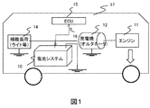
- FIG. 1 is an outline of the configuration of the micro HEV.
- a micro HEV 17 equipped with a battery system 10 (a pack composed of two kinds of secondary batteries, for example, a lead battery and a separate battery including a capacitor, which will be described later) is mechanically connected to the engine 11 and the engine 12.
- a generator 12 alternnator
- a light is connected to the engine 11 and the engine 12.
- an air conditioner fan is connected to the engine 11 and the engine 12.
- a starter and other supplementary loads is connected to a starter and other supplementary loads 14, an upper controller ECU 15, and a communication line 16.
- the electric power of the auxiliary load 14 of the micro HEV 17 is supplied from the battery system 10 when idling is stopped.
- the alternator 12 is rotated and operated by the rotational force (deceleration energy) from the tire generated by the coasting of the vehicle, and the electric energy generated by the alternator 12 is supplied to the auxiliary load 14 as electric power, and the battery.
- the secondary battery in the system 10 is configured to be charged.
- the voltage of the alternator 12 is the rated voltage (for example, 14V) of the auxiliary machine load 14.
- the alternator is usually a constant current power source. However, when the voltage reaches a predetermined value, the voltage is controlled to a constant voltage (14 V in a normal car) by control. That is, the alternator is regarded as a CCCV (Constant Current Constant Voltage) charger.
- the ECU controls the alternator On / Off and the mechanical brake during regeneration, and transmits a charging current to the power supply system.
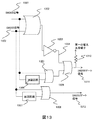
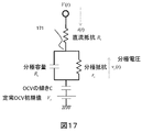
- FIG. 2 is a configuration diagram showing an outline of the battery system of the present invention.
- the battery system 10 includes a first battery (generally a lead battery) 201, an ammeter 202 that monitors the current of the first battery, a voltage sensing line 203 that monitors the voltage of the second battery, and the first battery.
- Current estimation unit 204 for estimating the current of the first battery
- switch SW 205 connected in series to the first battery
- second battery 206 ammeter 207 for monitoring the current of the second battery
- a voltage sensing line 208 a current estimation unit 209 for estimating the current of the second battery, a switch SW210 connected in series to the second battery, a comparator 211 for comparing the current, and a signal for controlling the switch SW.
- the switch control unit 212 to be created and the voltage sensing line 213 of the alternator / auxiliary machine are configured.
- the controller 200 includes a switch control unit 212, a comparator 211, and current estimation units 204 and 209.
- the controller 200 controls the On / Off state of the switch SW205 and the switch SW210 via the signal line 18 with respect to the current and voltage of each battery and information from the host controller 16. By switching the switch SW, it is possible to switch whether the current from the generator 12 is supplied to the first battery or the second battery.
- the switch control unit 212 in the controller 200 that directly controls the signal of the switch SW.
- the first battery may be used as a power source for the controller 200.
- both the switch SW205 and the switch SW210 prohibit the OFF state to prevent the loss of the auxiliary power supply.
- the switch SW205 and the switch SW210 may use a power MOS-FET, IGBT, or mechanical relay.
- the first battery 201 and the second battery 206 are discharged so as to supply power to the auxiliary load 14 in a certain state, and the electricity generated by the generator 13 when the micro HEV 17 is decelerated. Charged with energy.
- a lead battery As the first battery 201 and the second battery 206, a lead battery, a nickel metal hydride battery, a nickel zinc battery, a lithium ion battery, an electric double layer capacitor, a lithium ion capacitor, or the like can be used.
- a lead battery is used for the first battery 201. This is because a battery having a large capacity (Ah) is required to secure power for a safety device or the like that is parked for a long period of time.
- the second battery 206 may be a capacitor, a lithium ion capacitor, a lithium ion battery, a nickel zinc battery, or a nickel metal hydride battery designed to be charged with a large amount of normal current. Since the rated voltage of lithium ion capacitors and lithium ion batteries is generally in the range of 3V to 4.2V, the voltage range from 8V (a guideline for audio sound skipping voltage), which is a standard for the vehicle voltage range, to 14V. To fit, use 4 in series. In the case of a nickel metal hydride battery, 10 batteries are used. In the case of a nickel zinc battery, 8 to 10 batteries are used, and in the case of a capacitor, 7 batteries are used.
- the first battery 201 is a capacity type battery or a power storage element with an emphasis on capacity (Ah) such as a lead battery
- the second battery 206 is a lithium ion battery or a capacitor.
- the present invention is not limited to this, and the first battery 301 and the second battery 302 may be the same type of battery.
- a Hall element or a shunt ammeter can be used for the ammeter 202 of the first battery and the ammeter 207 of the second battery.
- the resistance and OCV of each battery are measured to determine the charging current.
- An estimation means is required, and the switch can be switched to a switch on / off combination that increases the total charge of each battery.
- the first battery 201 is based on the information obtained by the means for measuring the resistance and OCV of each battery and estimating the charging current. Since the switch SW is switched between the second battery 206 and the second battery 206, the battery system can improve the total charge amount even in the case of the first battery and the second battery having different properties such as resistance and capacity. Can be provided.
- the switch SW is switched to charge the other battery.
- the switch is switched only once between the start and end of regeneration.
- the switching timing for example, the current time series when only one battery is connected is estimated, the current time series of the first battery is I (t), and the current time series of the second battery is i (t). ), The time series I (T ⁇ ) and i ( ⁇ ) are compared and the solution ⁇ of the nonlinear equation is obtained so as to be equal.
- T is the regeneration time).
- the switch is switched a plurality of times from the start to the end of regeneration. Estimated currents of the first battery and the second battery are obtained at regular intervals, and each time the switch is switched to the larger estimated current of the estimated currents of the first battery and the second battery.
- the battery is in the constant current charging mode, the current is the same regardless of which battery is connected, so the following may be used.
- the switch SW is alternately switched between the first battery and the second battery so that the OCV of the battery with fast depolarization becomes constant.
- the switch is switched a plurality of times from the start to the end of regeneration, and both batteries may be connected to be charged at the same time.
- the switches of the two batteries are turned on.
- cross current can be prevented by combining control such as turning on the switch SW of only one battery whose charging current immediately increases. be able to.
- both the first battery and the second battery may be connected by setting the first switch and the second switch to On, but the number of switching of the switch SW is reduced. is there.
- the CC charging in the third embodiment one of the batteries is charged first, and the battery is charged to a voltage at which no cross current is generated even if it is arranged in parallel. After that, if no cross current is generated even if the parallel connection is made, the connection is made in parallel.
- one switch is provided at the point where one second battery of the first battery connected in parallel intersects. There may be more than one.
- the switches are the first switch and the second switch, and the first switch SW and the second switch SW are the first battery, The second battery is connected in parallel like the second battery, the first battery is connected to a load (auxiliary load 14, alternator 12, etc.) via the first switch SW, the second battery is The load is connected to the load via the second switch SW.
- both batteries are not turned On, and the OCV of the second battery is lowered at the next regeneration so that regenerative charging increases.
- the second battery is discharged first, and when the second battery reaches a predetermined voltage or charging rate, it is switched to the first battery, or the first battery is discharged first.
- the first battery reaches a predetermined voltage or charging rate, the battery is switched to the second battery and discharged.
- a current as high as 300 A is required. Therefore, there is a possibility that the first battery alone does not provide power and cannot be cranked. In this case, the power shortage may be compensated by connecting the first and second batteries in parallel, or the second battery may be connected to the first battery.
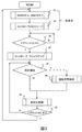
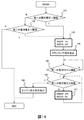
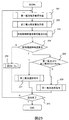
- Fig. 3 shows the outline of the overall control process after the vehicle is shipped from the factory or after the first battery replacement, from ignition on to off and parking.
- step 31 it is considered that the vehicle is parked, the switch SW205 is turned on and the switch SW210 is turned off.
- the controller 200 is set to sleep, and the power of the parked security device is used as the first battery. Let them take charge and shift to the low power consumption mode.
- step 34 to wake up the controller.
- step 35 it is determined whether or not regeneration is started. This determination is made based on a signal from the ECU 16. After the regeneration is started, the processing is shifted to the regenerative charge control in step 36. Details of this will be described in another embodiment.
- step 36 the process proceeds to non-regenerative control step 37. If it is determined in step 39 that the ignition is on, the process proceeds to step 35. If the ignition is off, the process proceeds to step 31 which is a parking process.
- the ignition switch signal obtains information from the ECU 16.
- step 35 to step 39 may be executed or determined periodically at an event of a control cycle (for example, 10 ms or 0.1 s).
- a control cycle for example, 10 ms or 0.1 s.
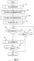
- FIG. 4 illustrates the non-regenerative control 37 in FIG.
- the non-regenerative control 37 is divided into two modes: a discharge mode and a forced charge mode.
- the discharge mode is divided into three processes of cranking when the charge charged in the second battery after the regenerative charge is large and when the second battery becomes empty and only the first battery is used.
- the forced charging mode is a case where both batteries are empty and the first battery is forcibly charged. This process will be described with reference to the example of FIG. Note that the processing in FIG. 4 is not executed during regeneration or when regeneration is started.
- step 41 it is determined whether or not the engine is cranking. If it is cranking, the process moves to the cranking process 42, and if not, the process moves to step 43. Information on whether or not cranking is in progress is obtained from the ECU 15.
- Step 42 executes switch SW processing during cranking. This process will be described later. After the end of step 42, the process of FIG.
- step 43 it is determined whether or not cranking is started. If cranking is started, the process proceeds to step 44. If cranking is not started, an alternator charge off command is sent to the ECU 15 in step 45 (this is to prevent deterioration of fuel consumption due to an extra output of the alternator from the viewpoint of fuel saving).
- the start of cranking is due to the convenience of the vehicle (for example, when the room temperature rises during idling stop because the air conditioner compressor is stopped during idling stop). This is a case where the battery becomes empty and the first battery needs to be forcibly charged. Information on the start of cranking for the convenience of the vehicle is obtained from the ECU 15.
- the determination as to whether or not the first battery is empty may be made when the charging rate of the first battery is equal to or lower than a preset charging rate.
- the preset charging rate may be, for example, 80% or 90% when a lead battery is used as the first battery.
- the voltage of the first battery may be set to be equal to or lower than a preset voltage.
- the preset voltage may be 12.4V or 12.6V.
- the alternator charging Off may be to stop the alternator or to adjust the power generation voltage of the alternator to the OCV of the battery (in this case, the power generation voltage adjustment function of the alternator is required).
- the current sum of 202 and 206 measured by an ammeter may be raised to the ECU 15 and voltage control by feedback may be performed by the ECU. After completion of step 45, the process proceeds to step 46.
- step 44 the first battery switch SW205 is set to On and the second battery switch SW210 is set to Off to prepare for cranking.
- the current switch SW state may be continued.
- step 46 it is determined whether or not the second battery is empty.
- the voltage of the second battery may be equal to or lower than a preset voltage.
- the preset voltage may be the rated voltage of the second battery ⁇ the series number of the second battery, or may be a voltage at which audio skipping occurs, for example, 8V. If the second battery is empty, the process proceeds to step 47. If the second battery is not empty, the process proceeds to step 48.
- step 47 in order to discharge the first battery, the switch SW205 is turned on and the switch SW210 is turned off. After step 47 ends, the flow of FIG. 4 ends.
- step 48 in order to discharge only the second battery, the switch SW205 is turned off and the switch SW210 is turned on. This is a process for emptying the second battery as much as possible at the time of discharge because it is desired to suck the charging current as much as possible in the next regeneration. After step 48, the flow of FIG. 4 is terminated.
- FIG. 4 The above flow of FIG. 4 is an example in which the second battery is discharged first, but the first battery may be discharged first.
- FIG. 5 illustrates the cranking process 42 in FIG.
- the On / Off state of the previous switch is the initial value of the On / Off state of the switch of FIG.
- step 501 it is determined whether or not both of the switch SW 205 and switch SW 210 are ON. If YES, the process proceeds to step 503. If NO (only one switch SW is ON), the process proceeds to step 504.
- step 502 it is determined whether or not the alternator / auxiliary voltage (measured by the voltage sensing line 213 in FIG. 2) is equal to or less than a predetermined threshold value. If it is equal to or smaller than the threshold value, the process proceeds to step 504, and if not, the process in FIG. 5 is terminated.
- the threshold value may be, for example, 8 V at which audio skips.
- the alternator / auxiliary voltage the value measured by the voltage sensing line 213 in FIG. 2 is used.
- step 504 an estimated current of each battery is obtained when both switches are assumed to be On, and it is determined whether one of the currents is charged (cross current). If a cross current occurs, the process proceeds to step 506 (a process for preventing a cross current). If no cross current is generated, the process proceeds to step 505.
- the estimated current as a material for determining the occurrence of cross current is estimated by the current estimation unit 204 in FIG. 2 for the first battery and the current estimation unit 209 in FIG. 2 for the second battery.
- this cross current determination method will be described.
- the OCV (Open Circuit Voltage) of the first battery is set to V1
- the OCV of the second battery is set to V2.
- the DC resistance of the first battery is R1
- the DC resistance of the second battery is R2
- the resistance of the switch SW205 is r1
- the DC resistance of the switch SW210 is r2. How to determine this value will be described later.
- Ia is converted from Pa (in this case, Pa may be the value received from ECU 15, or the current current x alternator / auxiliary voltage. Also, as a condition for enabling cranking, V * V / 4r ⁇ Pa. is there).
- V is the OCV of the battery, and R is the sum of the DC resistance and the switch SW resistance.
- V1 is the OCV of the first battery
- V2 is the OCV of the second battery
- R1 is the DC resistance of the first battery
- R2 is the DC resistance of the second battery
- r1 is the On resistance of the switch SW205
- r2 is the switch SW210. On resistance.
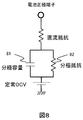
- FIG. 3 An equivalent circuit when two batteries are connected in parallel is expressed as FIG. This is because it can be considered that the OCV of the battery hardly changes in the control cycle (for example, 10 ms) of FIG.
- the current and voltage equations in FIG. 3 are derived from circuit equations.
- the current of the first battery is expressed by Equation 1
- the current of the second battery is expressed by Equation 2.
- the discharge direction is expressed as +.
- the current estimation unit 204 and Equation 2 can be estimated by the current estimation unit 205. If the first current is positive and the second current is positive, it is determined that no cross current is generated (conversely, if the current of the first battery ⁇ the current of the second battery ⁇ 0, the cross current is generated. to decide). This determination corresponds to the comparator 211 in FIG. Further, as a simpler cross current determination method, it may be determined that no cross current is generated as long as Expression 3 is satisfied. ⁇ (R1 + r1) ⁇ (V2 ⁇ V1) / Ia ⁇ (R2 + r2) (Formula 3)
- step 505 the switch SW205 (switch SW of the first battery) is turned on, the switch SW210 (switch SW of the second battery) is turned on and both batteries are placed in parallel, and the process of FIG.
- step 506 it is determined whether or not the first battery voltage is large based on the estimated battery voltage when the single battery connection is assumed. If the estimated voltage of the first battery is large, step 507 is performed. If not, step 507 is performed. The processing is moved to 508.
- the estimated voltage at the time of battery single connection the estimated voltage of the first battery is represented by Expression 4, and the estimated voltage of the second battery is represented by Expression 5.
- the estimation method of r1, R1, r2, R2, V1, and V2 will be described later.
- Estimated voltage of first battery V1 ⁇ (R1 + r1) Ia (Formula 4)
- Estimated voltage of second battery V2 ⁇ (R2 + r2) Ia (Formula 5)
- the value read by the voltage sensing line 203 is the estimated voltage of the first battery, and if only the switch SW210 of the second battery is On, the voltage sensing is performed.
- the value read by the linear flow meter 208 may be used as the estimated voltage of the second battery.
- step 507 since the voltage drop is smaller when the first battery is used, the switch SW205 is turned on and the switch SW210 is turned off, and the process of FIG. 5 is terminated.
- step 508 since the voltage drop is smaller when the second battery is used, the switch SW205 is turned off and the switch SW210 is turned on, and the process of FIG. 5 is terminated.
- step 503 since both switches SW are currently turned on, it is determined from the values of the ammeters 202 and 206 whether or not a cross current is generated. If not, the state of the switch SW is left as it is, and the process of FIG. 5 is terminated.
- step 509 since a cross current is generated, it is necessary to switch to the single battery connection, so it is determined whether or not the second battery should be used. If the second battery is usable, the process proceeds to step 511, and if not, the process proceeds to step 510.
- the determination as to whether the second battery can be used is based on a predetermined threshold value for the voltage of Formula 5 (for example, a voltage of 8 V without audio skipping may be used).
- step 510 since only the first battery can be used, the switch SW205 is turned on and the switch SW210 is turned off, and the processing of FIG.
- step 511 since the second battery can be used, the switch SW205 is turned off and the switch SW210 is turned on in order to preferentially use the second battery, and the process of FIG.
- the OCV of each battery may be a value read by a voltage sensing line when the switch SW is Open.
- the current I and resistance (the sum of the DC resistance of the battery and the On resistance of the switch SW) read from the value V obtained by reading the alternator / auxiliary voltage with the voltage sensing line. May be set to V-IR.
- the DC resistance may be set to
- the on resistance of the switch SW may be obtained in the same manner as the direct current resistance from the difference between the measured voltage of the battery and the alternator / auxiliary voltage when the switch SW was previously turned from On to Off or from Off to On. If this method is used, it is not necessary to pre-set the battery, and it can be handled even if the battery is replaced.
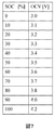
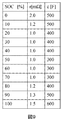
- the OCV is expressed as the sum of an OCV (steady OCV) after a sufficient time has elapsed and a transient voltage change (referred to as polarization) that changes in the order of several seconds. Since the steady OCV generally appears as a function of the battery charging rate, the table of FIG. 7 may be held, and the table of FIG. 7 may be interpolated by the SOC value to obtain the steady OCV ( FIG. 7 shows an example of a virtual battery.
- the charging rate was expressed as SOC (State of Charge).
- the SOC can be obtained by using the Kalman filter used in the literature “Shuichi Adachi, Ichiro Maruta: Basics of Kalman Filter, Tokyo Denki University Press, March 10, 2013, First Edition, Second Printing”, or ignition. From the battery voltage at the moment when is turned on, the SOC may be obtained in reverse from the table of FIG. 7 to obtain an initial value, and may be updated every moment as 100 ⁇ current integration value / battery capacity (current integration method). Further, the measured voltage-DC resistance ⁇ current-polarization voltage is regarded as a steady OCV, and the SOC may be obtained in reverse from the table of FIG. ). Further, the current integration method and the voltage estimation method may be weighted and averaged.
- Formula 6 may be simplified and Formula 7 may be used.
- vp (t) vp (t ⁇ t) * (1 ⁇ t / cr) + I (t) ⁇ ⁇ t / c (Expression 7)
- ⁇ t time increment of current measurement
- vp polarization voltage
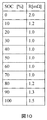
- the values of c and r are required, they may be prepared as the table of FIG. Specifically, the values of c and r are obtained by interpolating the table of FIG. 9 based on the SOC value described above. Note that c and r may vary depending on the temperature. In that case, a thermometer may be attached to each battery, the table of FIG. 9 may be prepared for each temperature, and a value may be obtained by interpolation based on the measured temperature.
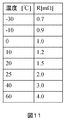
- DC resistance and switch SW resistance an example of a DC resistance table is shown in FIG. Similarly, values may be obtained by interpolation in the table of FIG. Further, the value of the direct current resistance may change depending on the temperature.
- a thermometer may be attached to each battery, and the table of FIG. 10 may be prepared for each temperature, and a value may be obtained by interpolation based on the measured temperature.
- One value of the switch SW resistor may be stored in the controller 200, or a table example for each temperature may be held and the value may be interpolated by a thermometer of the controller.
- the DC resistance and the switch SW resistance the values estimated from the measurement values described above may be used.
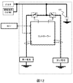
- the battery when switching the switch SW, the battery may not be connected instantaneously depending on the switch SW switching timing.
- the configuration shown in FIG. 12 may be adopted in which a capacitor 121 is inserted in the power supply system shown in FIG.
- the switch control unit 212 may be provided with a circuit for preventing both batteries from being turned off when only one battery is switched to On. An example of this gate circuit is shown in FIG.
- the switch SW205 signal 1301 and the switch SW210 signal 1302 are inputted, and the switch SW205 gate signal 1311 and the switch SW1312 gate signal 1312 are created.
- the switch SW205 signal and the switch SW210 signal are the SW signals in FIG. 3, FIG. 4, and FIG. 5 (TTL; Transistor and Transistor Logic signal may also be used).
- TTL Transistor and Transistor Logic signal may also be used.
- 1 is defined as ON
- 0 is defined as OFF.
- the switch SW205 gate signal refers to the signal line of the switch SW205 in FIG. 2
- the switch SW210 gate signal refers to the signal line of the switch SW210 in FIG.
- FIG. 13 corresponds to the SW control unit 212 in FIG.
- the OR gate 1302 and the NOT gate determine a condition in which both are turned off.
- the signal that turns off both is 1304.
- the OR gate 1309 uses the switch SW205 gate signal as the OR of the switch SW205 signal candidate and both OFF signals. To do. Since the controller 200 is in a sleep state during parking, the power of each gate is turned off. In that case, in order to use the first battery as the power source of the security device, the pull-up resistor 1310 is used to forcibly set the signal to 1 and hold the switch SW205 as On.
- the switch SW terminal When a mechanical relay is used for the switch SW205, the switch SW terminal may be connected so that the relay is turned on at the position where the gate current (relay electromagnet) becomes 0. Is not necessary. In addition, this is not the case when a relay of a latch-up type (a type that maintains the previous switch SW state even when the electromagnet current stops flowing) is used as a mechanical relay (no pull-up resistor is required and the current is 0). It is not necessary to consider the switch SW terminal in consideration of the time state). If switch SW20 When an FET or IGBT is used for 5, an FET (or IGBT) driver may be further added. In this case, the FET driver does not turn off the power while parking.
- the switch SW205 is connected in parallel so that it is turned on when the electromagnet current is set to 0, and the switch with the ignition ON is set.
- the SW operation may be shared by the FET so that the life of the mechanical relay is extended.
- a pull-up resistor when a pull-up resistor is not used, a diode may be connected in parallel to the switch SW205 (the current direction of the diode is from the first battery to the alternator / auxiliary side).
- a pull-down resistor may be inserted in the gate of the switch SW210.
- the delay circuit may be a circuit in which an integration circuit is connected to the gate signal and the output of the integration circuit is received by a Schmitt trigger.
- the time constant of the integration circuit may be determined as the delay time as a value set in advance by the ON delay time of the switch SW + the delay time of the gate.
- FIG. 13 shows a circuit
- the logic of the program corresponding to FIG. 13 may be used (when a pull-up resistor is inserted, a pull-up resistor is attached to the I / O signal of the CPU used as the switch SW205 gate signal).
- the pull-up resistor and pull-down resistor described above may change depending on whether the FET is a P channel or an N channel, and whether the FET is connected to the positive voltage of GND or the first battery. What is necessary is just to connect so that SW210 may be turned off.
- step 141 it is determined whether or not the first battery voltage (matching OCV) is below a certain threshold. If it is less than the threshold value, the process proceeds to step 143. If it is equal to or greater than the threshold value, the process proceeds to step 142.
- the threshold value here may be set in advance as a value corresponding to a voltage of SOC 80% or 90%. In this case, the charge rate and OCV table (FIG. 7) of the first battery must be retained.
- step 143 since the charging rate of the first battery is insufficient, the switch SW205 is turned on and the switch SW210 is turned off, and the process proceeds to step 144.
- step 144 a cranking command is issued to start charging the first battery, and the process proceeds to step 145.
- the driver may wait until the driver cranks the engine without sending the cranking command.
- step 145 the process is repeated until the charging rate of the first battery becomes equal to or higher than the first battery.
- the procedure for obtaining the charging rate is described here.
- charging is started, and the current time series i (t) after the current becomes CV charging is regarded as an exponential function and approximated by a function (determining coefficients x, y, and z in Expression 8).
- Whether or not the charging rate is a specified value may be determined by using z obtained in Expression 9 and determining that Step 146 is satisfied when Expression 10 is satisfied. Equation 9 needs to store the past time series, and may not be calculated by the CPU specifications of the controller 200. In that case, recursive least squares (Sagara, Akizuki, Nakamizo, Katayama: System Identification, Society of Instrument and Control Engineers, 1981) that updates the time series one by one may be used. As the target charging rate, the value of the charging rate (for example, 80%, 90%) used in step 141 may be used. OCV of target charging rate ⁇ initial OCV ⁇ Q (t) * z (Expression 10)
- step 146 it is determined whether the voltage of the second battery is equal to or higher than the threshold value. If the voltage is less than the threshold value, the process proceeds to step 147, the switch SW205 is turned off and the switch SW210 is turned on. Repeat until the voltage reaches the threshold. When the voltage of the second battery becomes equal to or higher than the threshold value, the process proceeds to step 148, and a command to stop the engine is sent to the ECU 15. If idling is stopped, the alternator may be stopped on the ECU side. Then, the flow of FIG. 14 is terminated.
- the threshold is the minimum voltage of the second battery described above.
- step 142 it is determined whether or not the voltage of the second battery is less than the threshold value, and if it is less than the threshold value, the second battery needs to be charged, and thus the process proceeds to step 143. If it is equal to or greater than the threshold value, the processing in FIG. 14 is terminated.
- the threshold value here is the same value as the threshold value described in step 146.
- the estimated charging current is transmitted to the ECU 15.
- mechanical brake emphasis control may be performed in order to prevent torque discontinuity during braking and improve ride comfort.
- charging power may be transmitted to the ECU 15 instead of the charging current. Charging power is calculated as estimated charging current x alternator / auxiliary voltage.
- Example 1 in which the switch is switched only once from the start to the end of regeneration will be described (36 in FIG. 3).
- the switching timing for example, the current time series when only one battery is connected is estimated, the current time series of the first battery is I (t), and the current time series of the second battery is i (t). ), The time series I (T ⁇ ) and i ( ⁇ ) are compared and the solution ⁇ of the nonlinear equation is obtained so as to be equal.
- T is the regeneration time.
- Fig. 15 shows an example of regenerative charge control processing.
- the second battery is selected first (the first battery may be charged first, an example of which will be described later).
- the switch SW205 is set to Off and the switch SW210 is set to On.
- step 152 the estimated current time series i1 (t) when only the first battery is selected is received. This estimated current time series is calculated by the current estimation unit 204 in FIG.
- step 153 the estimated current time series i2 (t) when only the second battery is selected is received. This estimated current time series is calculated by the current estimation unit 209 in FIG.
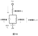
- FIG. 16 assumes an equivalent circuit of a large capacity battery.
- the current time series i (t) of Expression 11 is obtained by solving the circuit equation of FIG.
- a function of Formula 11, Formula 12, and Formula 13 is determined according to the type of the first battery, the second battery, and each battery, the coefficient is calculated, and the coefficient is sent.
- the current time series in the CC charge time, Ia, and CV charge periods may be sent.
- This time series may be a time series every 1 s or every 0.5 s.
- the CC charging time ⁇ of a small-capacity battery is Lambert's W function, but Lambert's W function is a fast and accurate numerical calculation method (reference, Chapeau-Blondeau, F. and Monitor, A: Evaluation of the Lambert. W Function and Application to Generation of Generalized Gaussian Noise With Exponent 1/2, IEEE Trans.
- a W function table may be set in advance and a value may be obtained by interpolation. Next, how to obtain each coefficient in Equation 11, Equation 12, and Equation 13 will be described.
- the DC resistance and the switch SW resistance may be obtained by the ratio of the past current change and voltage change, or may be a value set in advance in a table.
- the initial OCV may be measured voltage value ⁇ polarization voltage when the switch SW connected to each battery is OFF. The problem here is the polarization voltage. If the polarization capacity and the polarization resistance are known, the polarization voltage may be obtained by calculation according to Equation 6 to Equation 7 using the measurement current.
- the polarization capacity and the polarization resistance may be obtained by interpolation by holding a table (however, a table for charging is prepared separately) or by past time series data.
- measurement data at the time of the previous CV charge may be used and obtained as Equation 9 (however, V and I are obtained from measured values at the time of charge, and Q, f, and g are obtained).
- Equation 9 V and I are obtained from measured values at the time of charge, and Q, f, and g are obtained.
- x ⁇ polarization capacity ⁇ polarization resistance
- y polarization resistance ⁇ (1 + polarization capacity / capacitance C)
- z 1 / capacitance C
- the switching time ⁇ is determined so that the charge is maximized. This idea is described. If the current time series of the first battery is i1 (t), the current time series of the second battery is i2 (t), and the regeneration time is T, the charge charge Q at the time of regeneration is expressed by Equation 14.
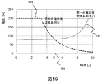
- Equation 15 is a nonlinear equation. An image of the solution is shown in FIG. Here, i2 is 191 (corresponding to i2 ( ⁇ )), and i1 is plotted with the time axis reversed (corresponding to i1 (T ⁇ )). This intersection 193 is the solution ⁇ of Equation 15. Therefore, the current at the switching time ⁇ of the second battery coincides with the current at the end of regeneration of the first battery.
- the regeneration time is T
- the charging time of the second battery is ⁇ (T> ⁇ )
- the first charging time is T ⁇
- the charge amounts of the first battery and the second battery are maximized.
- the switch SW is switched at the timing ⁇ (the first battery and the second battery may be reversed).
- ⁇ is a value obtained by integrating the charging time and current value of the second battery from the expression obtained by plotting the charging time and current value of the second battery, and an expression obtained by plotting the charging time and current value of the first battery in reverse.
- the total value of the values integrated in the range up to is the maximum timing during the regeneration time T.
- the nonlinear equation of Equation 15 may use Newton's method or may be solved using a bisection method (references, Mitoda, Suda: Numerical calculation method 2nd edition, Morikita Publishing, 2014). In order to calculate the value of the current function in the middle of the numerical calculation, the above-described equation may be used, or the function value may be calculated by interpolation when given as time series data.
- i1 may deviate from the estimated current time series because the absolute value of the polarization voltage decreases due to ⁇ .
- the function of Expression 16 may be used as the correction of ⁇ in Expression 11
- the function of Expression 17 may be used as the correction of Expression 12.
- Formula 15 is a case where the regeneration end time T is known.
- T is good when information can be obtained from the ECU (in this case, for example, T may be obtained from the speed and deceleration on the ECU 15 side), but it is often unknown.
- T is unknown, the first battery uses a large-capacity battery, so i1 may be calculated as I ⁇ , and a typical time required for regeneration (for example, 5 s or 10 s) is prepared in advance. You may keep it.
- step 155 it is determined whether the elapsed time from the start of regeneration is ⁇ or more. If it is equal to or larger than ⁇ , the process proceeds to step 157; otherwise, the process proceeds to step 156.
- step 156 it is determined whether or not regeneration has ended. If regeneration has not ended, the process returns to step 155. Whether the regeneration is completed is determined by a signal from the ECU 15 or whether the sum value of the ammeter is 0 or more. If regeneration is completed, the processing in FIG. 15 is terminated.
- step 157 a selection command for the second battery is sent to the switch SW. Specifically, the switch SW205 is turned on and the switch SW210 is turned off. After switching the switch SW, the process proceeds to step 158. Step 158 terminates the processing of FIG. 15 when regeneration is finished.
- the second battery is turned on first, but the first battery may be turned on first.
- the switch is switched a plurality of times from the start to the end of regeneration.
- the estimated currents of the first battery and the second battery are obtained at regular intervals, and each time the switch is switched to the larger estimated current of the estimated currents of the first battery and the second battery to perform charging.
- the switch is switched periodically.
- the switch is switched to the larger one of the estimated currents of the first battery and the second battery to perform charging. This will be described in detail below.
- FIG. 20 is implemented instead of FIG. 15 in the first embodiment.
- step 2001 the estimated current i1 immediately after connecting only the first battery is received.
- This calculation is performed by the current estimation unit 204 in FIG.
- the current switch SW205 is OFF, (CV voltage of alternator ⁇ measured voltage of the first battery) / (DC resistance of the first battery + On resistance of the switch SW205).
- the method described in the first embodiment is used for the DC resistance and the On resistance of the switch SW. If the current switch SW205 is On, the measured current value is used. Thereafter, the process proceeds to step 2002.
- step 2002 the estimated current i2 immediately after connecting only the second battery is received.
- This calculation is performed by the current estimation unit 209 in FIG. 2 (hereinafter, the current is assumed to have a charge direction of +).
- the current is assumed to have a charge direction of +.
- the calculation method when the switch SW210 is currently OFF, (CV voltage of the alternator ⁇ measurement voltage of the second battery) / (DC resistance of the second battery + On resistance of the switch SW210). The method described in the first embodiment is used for the DC resistance and the On resistance of the switch SW. If the current switch SW210 is On, the measured current value is used. Thereafter, the process proceeds to step 2003.
- step 2003 it is determined whether or not both batteries are CC charged (constant current charging). If both batteries are CC charged, the process proceeds to step 2008. If not, the process proceeds to step 2004.
- Ia alternative generated current ⁇ auxiliary machine current
- i1 ⁇ Ia and i2 ⁇ Ia are used, and i1 ⁇ Ia and i2 ⁇ Ia.
- step 2004, i1 and i2 are compared, and if i1 is large, the process proceeds to step 2005, and if not, the process proceeds to step 2006.
- step 2005 a switch SW command for selecting the first battery is sent. Specifically, the switch SW205 is set to On and the switch SW210 is set to Off. Thereafter, the process proceeds to step 2007.
- step 2006 a switch SW command for selecting the second battery is sent. Specifically, the switch SW205 is set to Off and the switch SW210 is set to On. Thereafter, the process proceeds to step 2007. This is to increase the charge charge by selecting the battery with the higher charge current.
- step 2008 CC charging is performed regardless of which battery is connected, so a process of extending the CC charging time “CC charging SW selection process” is executed. This process will be described later. After step 2008, the process proceeds to step 2007.
- step 2007, it is determined whether or not the regeneration is finished. If not finished, the process proceeds to step 2001. If finished, the process of FIG. 20 is finished. These processes may be returned to the process of step 2001 every measurement cycle (for example, every 10 ms) or every 0.1 s.
- the duty ratio between the time for selecting the first battery and the time for selecting the second battery may be switched as ⁇ : 1 ⁇ (0 ⁇ ⁇ ⁇ 1). ).
- the switch SW switching may be performed periodically.
- ⁇ may be a predetermined value, the method shown in FIG. 21 may be used, or ⁇ may be changed according to the measured voltage or current.
- the aim of this process is to alternately switch batteries to rest one battery, reduce the polarization voltage, increase the next charging current, extend the total CC charging time, and increase the charging charge during regeneration There is.
- step 2101 it is determined whether or not the estimated current of the first battery is less than the CC charging current Ia. If it is less than Ia, the process proceeds to step 2102, and if not, the process proceeds to step 2103.
- step 2102 a command is sent to the first battery to select the switch SW. Specifically, the switch SW205 is set to On and the switch SW210 is set to Off. Thereafter, the processing in step FIG. 21 is terminated (the processing is transferred to step 2007 in FIG. 20).
- step 2103 a command is sent to the second battery to select the switch SW. Specifically, the switch SW205 is set to Off and the switch SW210 is set to On. Thereafter, the processing in step FIG. 21 is terminated (the processing is transferred to step 2007 in FIG. 20).
- CC charging of the first battery ends first. Thereafter, it is assumed that the second battery is CC-charged by ⁇ t (equivalent to resting the first battery). In the meantime, the polarization voltage of the first battery decreases by ⁇ t ⁇ vp / cLrL (vp is the polarization voltage when CC charging is completed, cL is the polarization capacity, and rL is the polarization resistance). Therefore, when switching to the first battery next time, CC charging can be performed by ⁇ t ⁇ vp / (Ia * rL ⁇ vp). For this reason, the CC charge time of the first battery is further extended, and the charge charge increases. In addition, the ratio of the On time of the first battery and the On time of the second battery is changed to vp: Ia * rL-vp with the duty ratio. The reason why priority is given to the CC charging of the first battery will be described below.
- Equation 19 is equivalent to maximizing Equation 20 from the circuit equation of FIG.
- vL-vp ⁇ 0 and vL should be close to vp at the fastest speed.
- the first battery is connected to the first battery in order to bring the polarization voltage of the first battery close to vp at the fastest speed.
- the voltage time increase rate of the first battery may be m1, and ⁇ may be determined using Equation 21 (provided with a limiter in the range of 0 ⁇ ⁇ ⁇ 1). Equation 21 is derived from a circuit equation when it is assumed that a substantial current of ⁇ * Ia flows in the polarization.
- ⁇ may be determined by Equation 22 with the voltage time increase rate of the small capacity battery as m2 (however, a limiter in the range of 0 ⁇ ⁇ ⁇ 1 is attached). This is derived from a circuit equation when it is assumed that a substantial current (1- ⁇ ) Ia flows in the polarization of the small capacity battery (second battery).
- Equation 23 when it is desired to match the CC charging end time of the first battery with the CC charging end time of the second battery from time t1, the relationship between m1 and m2 expressed by Equation 23 may be used.
- Vs (t1) may be a voltage when the switch SW210 of the second battery is Off, or may be a terminal voltage of the second battery -IaRa when the switch SW210 is On.
- m2 0 is set in Equation 22.
- the switch SW switching control may be performed by determining the duty ratio as ⁇ in the case.
- the switch is switched a plurality of times from the start to the end of regeneration, and both batteries may be connected to be charged at the same time.
- the switches of the two batteries are turned on.
- cross current can be prevented by combining control such as turning on the switch SW of only one battery whose charging current immediately increases. be able to.
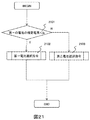
- FIG. 22 is implemented instead of FIG. 15 in the first embodiment.
- step 2201 a charging current i1 when only the first battery is connected is estimated. This is the same as the method described in the second embodiment.
- step 2202 the charging current i2 when only the second battery is connected is estimated. This is the same as the method described in the second embodiment.
- step 2203 the charging current of each battery when both the first battery and the second battery are connected (the first battery current is I1 and the second battery current is I2) is estimated.
- I1 and I2 An equivalent circuit when connected in parallel is shown in FIG.
- I1 and I2 can be calculated by reversing the sign of the current (at the time of CC charging).
- CV charging is determined as CV charging if the voltage V in FIG. 6 is equal to or higher than Va (CV voltage of the alternator).
- Va CV voltage of the alternator
- the DC resistance, the On resistance of the switch SW, and the OCV of each battery are estimated by the method described in the first embodiment.
- the measured current may be used.
- step 2204 it is determined whether both i1 and i2 are equal to or greater than the CC charging current Ia (whether only one of the first and second batteries is used results in CC charging). If either battery is connected and CC charging is performed, the process proceeds to step 2205. If not, the process proceeds to step 2206.
- step 2205 a switch SW selection process at the time of CC charging (the same process as the CC charging process in FIG. 21 described in the second embodiment) is executed, and the process proceeds to step 2207.
- step 2206 it is determined whether or not a cross current is generated when simultaneous connections are made. If a cross current occurs, the process proceeds to step 2208. If not, the process proceeds to 2210. As this determination method, I1 ⁇ 0 or I2 ⁇ 0.
- step 2208 since a cross current is generated in the simultaneous connection, it is determined to select one of the batteries. If the estimated current of the first battery> the estimated current of the second battery, the process proceeds to Step 2209; otherwise, the process proceeds to Step 2211.
- step 2209 a command for selecting the first battery (switch SW 205 is turned on and switch SW 210 is turned off) is sent, and the process proceeds to step 2207.
- step 2211 a command for selecting the second battery (switch SW 205 is turned off and switch SW 210 is turned on) is sent, and the process proceeds to step 2207.
- step 2210 a command for selecting both batteries (switch SW 205 and switch SW 210 are turned on) is sent, and the process proceeds to step 2207.
- step 2007, it is determined whether or not regeneration has ended. If not, the process proceeds to step 2201, and if not (if completed), the process in FIG. 22 is terminated.
- Equation 27 is obtained.
- Equation 28 least squares or recursive least squares may be used to obtain x, y, z, and C, cs, rs may be obtained from x, y, z.
- Equation 28 VL * t-RL * Q (t)
- X, rs, VL may be obtained using Equation 29 using least squares or recursive least squares, and cs may be obtained from x.
- the battery parameter of charge and discharge may differ depending on a battery. In this case, the battery parameters may be similarly identified using the data at the time of discharging.
- the lead battery alone, the capacitor alone, the lead battery and the capacitor always in parallel that is, the initial OCV of the lithium ion capacitor is the same as the lead battery 12.6 V
- the switch SW single switching method described in the first embodiment the second embodiment
- FIG. 24 shows a comparison result obtained by numerical calculation with a time step width of 50 ms.
- the proposed method (Example 1, Example 2, Example 3) requires more charge than the battery alone or always in parallel.
- Example 3 has the most charge charge. This is because the CC charging time is increased because simultaneous connection is allowed.
- the reason why the charging charge is always low in parallel is that the initial voltage of the capacitor is as low as 12.6 V, and the charge that can be charged by the capacitor is reduced.
- a second embodiment of the micro HEV of the present invention will be described.
- the first battery is charged to a voltage at which no cross current is generated, and then is paralleled.
- the CC time is not increased by using the drop in the polarization voltage. Therefore, although the charge charge is reduced as compared with the third embodiment, the number of switching of the switch SW is reduced and noise can be suppressed.
- Step 254 it is determined whether or not a cross current occurs at the time of simultaneous connection. If no cross current occurs, the process moves to step 255, and both switches SW are turned on. If cross current occurs, the process proceeds to step 256.
- step 256 the voltage shortage condition of the second battery, that is, “V1-V2> Ia * Rc” is determined.
- V1 is the OCV of the first battery (unsteady value, i.e., the battery voltage at zero current)
- V2 is the OCV of the second battery (unsteady value, i.e., the battery voltage at zero current)
- Rc is the DC resistance of the second battery. If the voltage of the second battery is insufficient, the process proceeds to step 257 where the second battery is selected and only the second battery is charged. Otherwise, since the voltage of the first battery is insufficient, the process moves to step 258 to select the first battery and charge only the first battery.
- step 259 it is determined whether or not the regeneration is completed. If regeneration is not completed, the process returns to step 251. If regeneration is completed, the process in FIG. 25 is terminated.
- SW (switch) control unit 213 ... Alternator (alternator) Auxiliary voltage sensing wire, 31 ... Parking switch position setting step, 32 ... Controller sleep step, 33 ... Ignition on determination, 34 ... Control -Wake-up step, 35 ... Regeneration start determination, 36 ... Regenerative charge control step, 37 ... Non-regenerative control step, 38 ... Ignition off determination, 41 ... Cranking determination, 42 ... Cranking processing step, 43 ... Cranking Start determination, 44 ... Cranking start command, 45 ... Alternator charge off command step, 46 ... Determination of whether the second battery is empty, 47 ... First battery discharge command step, 48 ... Second battery discharge command step, 501 ...
- Simultaneous connection determination 502 ... Alter accessory voltage threshold value determination, 503 ... Cross current generation determination, 504 ... Cross current generation determination during simultaneous connection, 505 ... Simultaneous connection command step, 506 ... Voltage comparison determination during single battery connection, 507 ... Connection command step for only the first battery, 508... Connection command step for only the second battery, 509.
- Usability determination 510 Connection command step for only the first battery 511: Connection command step for only the second battery 81: Polarization capacity 82: Polarization resistance 121 121 Backup capacitor 1301 First battery On signal 1302 ... Second battery On signal, 1302 ... Battery Off determination OR gate, 1303 ... Battery Off determination NOT gate, 1304 ... Battery Off determination signal, 1305 ...
- First battery estimated current time series reception step 153 ... Second battery estimated current time series reception step, 154 ... Switching time calculation step, 155 ... Regeneration elapsed time switching time determination, 156 ... Regeneration end determination, 157 ... Second battery selection command, 158 ... Regeneration end determination, 171 ... Small capacity battery OCV, 191 ... Second battery current time series, 192 ... First battery current time series, 193 ... Switching time 2001 ... First battery estimated current receiving step, 2002 ... Second battery estimated current receiving step, 2003 ... First Whether to charge CC even when the battery and the second battery are used alone, 2004, first battery estimated current and second battery estimated current comparison judgment, 2005 ... first battery selection command step, 2006 ... second battery step, 2007 ... regeneration End determination, 2008 ...
- Switch SW selection process step during CC charging, 2010 ... First battery estimated current CC less than current determination, 2102 ... First battery selection command, 2013 ... Second battery selection command, 2201 ... First battery estimation Current reception step, 2202 ... second battery estimated current reception step, 2203 ... simultaneous connection battery estimated current reception, 2204 ... determination of CC charge even when the first battery and second battery are used alone, 2205 ... CC charge switch SW Selection processing step, 2206 ... Cross current generation determination at the time of simultaneous connection, 2207 ... Regeneration end determination, 2208 ... First battery estimated current Second battery estimation Current comparison, 2209 ... first battery selection command step, 2210 ... both battery simultaneous connection command step, 2211 ... second battery selection command step, 251 ... first battery estimated current reception step, 252 ...
- Second battery estimated current reception Step 253 Battery estimated current reception at the time of simultaneous connection, 254 ... Cross current determination at the time of simultaneous connection, 255 ... Both battery connection processing, 256 ... Second battery voltage shortage determination, 257 ... Second battery selection command, 258 ... First battery Selection command, 259 ... Regeneration end determination
Abstract
Description
第一の電池の電流={-(V2-V1)+(R2+r2)Ia}/(R1+r1+R2+r2)…(式1)
第二の電池の電流={(V2-V1)+(R1+r1)Ia}/(R1+r1+R2+r2)…(式2)
-(R1+r1)≦(V2-V1)/Ia≦(R2+r2)…(式3)
第一の電池の推定電圧=V1-(R1+r1)Ia…(式4)
第二の電池の推定電圧=V2-(R2+r2)Ia…(式5)
分極電圧=I(t)*exp(-t/cr)/cr …(式6)
I(t):計測した電池電流(充電方向を+とする)
*:畳み込み積分
vp(t)=vp(t-Δt)*(1-Δt/cr)+I(t)×Δt/c …(式7)
Δt:電流計測の時間刻み幅
vp:分極電圧
5にFETやIGBTを使用する場合には、FET(もしくはIGBT)ドライバーを更に追加する場合がある。この場合にはFETドライバーは、駐車中でも電源を落とさないようにする。もしFETドライバーの消費電流が大きい場合には、スィッチSW205についてのみ、機械式リレーを並列に接続して、電磁石の電流を0にした場合にOnとなるようにしておき、イグニッションがON中のスィッチSW動作をFETに分担させ、機械式リレーの寿命が長くなるようにしても良い。もしくは、プルアップ抵抗を使わない場合にはスィッチSW205にダイオードを並列に繋いでおいても良い(ダイオードの電流方向は第一の電池からオルタ・補機側とする)。また、スィッチSW210にFETを使う場合には、駐車中にOffとしておいた方が良いため、スィッチSW210のゲートにプルダウン抵抗を入れておいても良い。


目標の充電率のOCV-初期OCV≧Q(t)*z …(式10)


i2(τ)=i1(T-τ) …式15


次に、ステップ2205にて、CC充電期間に同時Onを許す処理を入れても良い。この方法について述べる。第一の電池のみを接続する時間:第二の電池のみを接続する時間:両方の電池を接続する時間=η:ζ:1-η―ζとする(0<η,ζ<1)。そして、η、ζは予め与えられた値に従い制御しても良い。


Claims (24)
- スィッチSWを介して、第一の電池と第二の電池を並列に接続する電池システムにおいて、
少なくとも前記第一の電池の内部抵抗から前記第一の電池の充電電流を推定する手段および、少なくとも前記第二の電池の内部抵抗から前記第二の電池の充電電流を推定する手段を有し、
前記第一の電池の充電電流と前記第二の電池の充電電流に基づいて、前記第一の電池と前記第二の電池への充電電荷の和が大きくなる方式にて前記スィッチSWを切り替えることを特徴とする電池システム。 - 請求項1において、
前記スィッチSWは、第一のスィッチSWおよび第二のスィッチSWであり、
前記第一のスィッチSWと前記第二のスィッチSWとは並列に接続されており、
前記第一の電池は、前記第一のスィッチSWを介して負荷と接続されており、
前記第二の電池は、前記第二のスィッチSWを介して前記負荷と接続されている電池システム。 - 請求項1において、
放電時には第二の電池を先に放電させ、第二の電池が予め定められた電圧または充電率になったときに、第一の電池に切り替え放電する、または、
前記第一の電池を先に放電させ、第一の電池が予め定められた電圧または充電率になったときに、前記第二の電池に切り替え放電することを特徴とする電池システム。 - 請求項1ないし請求項3のいずれかにおいて、
前記方式は、回生充電時に前記スィッチSWを一度切り替えるものであり、
回生時間をT、第二の電池の充電時間をτ(T>τ)、第一の充電時間をT-τとした時に、まず第二の電池の充電を行い、
第一の電池と前記第二の電池の充電量が最大となるタイミングτで前記第一の電池に前記スィッチSWの切り替えを行うことを特徴とする電池システム。 - 請求項4において、
前記τは、第一の電池の電流時系列(i1(t))と第二の電池の時系列(i2(t))を推定し、i1(t)=i2(充電終了時間-t)となる充電開始からの時刻tであり、初めに前記第二の電池を充電し、充電開始からt経過後に第一の電池を選ぶように前記スィッチSWを切り替えることを特徴とする電池システム。 - 請求項4または請求項5において、
回生充電時間Tが不明の場合、第一の電池の電流時系=第二の電池の電流収束値となる時刻tを求め、前記τとすることを特徴とする電池システム。 - 請求項1ないし請求項3のいずれかにおいて、
前記方式は、回生充電時に前記スィッチSWを複数回切り替えるものであり、
前記第一の電池の推定充電電流と前記第二の電池の推定電流を比較し、推定電流の大きい方の電池を選択するようにスィッチSWを切り替え充電することを特徴とする電池システム。 - 請求項7において、
前記第一の電池、前記第二の電池単独充電のどちらかが定電圧充電となるまでは、定期的にスィッチSWを切り替え、充電することを特徴とする電池システム。 - 請求項8において、
前記第一の電池が定電流充電となる場合、前記第一の電池のスィッチSWの時間比率を初め1とし、前記第一の電池が定電流充電終了状態になった後に、前記第一の電池のスィッチSW時間比を、(オルタネータの定電圧充電時の電圧―第一の電池の開放電圧)/(オルタネータの定電流充電時の電流×分極抵抗)とすることを特徴とする電池システム。 - 請求項8において、
前記負荷はオルタネータであり、
前記第一の電池が定電流充電となる場合、前記オルタネータの定電流充電時の電流=第二の電池の分極電圧/(第二の電池の分極抵抗*(1+第二の電池の分極容量/第二の電池の容量))+第一の電池の分極電圧vp(t)/第一の電池の分極電圧となるように、前記第一の電池のスィッチSWの時間比率を制御することを特徴とする電池システム。 - 請求項1ないし請求項3のいずれかにおいて、
前記方式は、回生充電時に前記スィッチSWを複数回切り替えるものであり、
充電時に前記スィッチSWを複数回切り替えかつ、同時接続を許す場合、第一の電池単独、第二の電池単独充電、第一第二の電池両方を繋いだ時の3つ場合の第一電池、第二電池の充電電流を推定し、第一の電池もしくは第二の電池が放電となる場合には、第一の電池と第二の電池の充電電流の大きい方の電池を接続するようにスィッチSWを切り替え、そうでない場合に、単独電池では定電圧充電となる場合、第一第二の電池両方を接続し、更にそうでない場合には、第一の電池単独のスィッチSWオン時間、第二の電池単独のスィッチSWオン時間、両方の電池を接続するスィッチSW時間の比率を制御して、定電流充電となるようにすることを特徴とする電池システム。 - 請求項11において、
前記第一の電池単独の前記のスィッチSWのオン時間、前記第二の電池単独の前記スィッチSWのオン時間、両方の電池を接続するスィッチSW時間の比率を予め定められた値とすることを特徴とする電池システム。 - 請求項11において、
前記第一の電池単独のスィッチSWオン時間、前記第二の電池単独のスィッチSWのオン時間、両方の電池を接続するスィッチSW時間の比率として、両方の電池を接続するスィッチSW時間の比率を0とし、初めに第一の電池のスィッチSWの時間比率を初め1とし、前記第一の電池が定電流充電終了状態になった後に、第一の電池のスィッチSW時間比を、(オルタネータの定電圧充電時の電圧―第一の電池の開放電圧)/(オルタネータの定電流充電時の電流×分極抵抗)とすることを特徴とする電池システム。 - 請求項11において、
前記第一の電池単独のスィッチSWオン時間、前記第二の電池単独のスィッチSWオン時間、両方の電池を接続するスィッチSW時間の比率として、両方の電池を接続するスィッチSW時間の比率を0とし、オルタネータの定電流充電時の電流=第二の電池の分極電圧/(第二の電池の分極抵抗*(1+第二の電池の分極容量/第二の電池の容量(F換算値)))+第一の電池の分極電圧/第一の電池の分極抵抗となるように、前記第一の電池のスィッチSWの時間比率を制御することを特徴とする電池システム。 - 請求項1ないし請求項14のいずれかにおいて、
前記第一の電池の電圧、電流、前記第二の電池の電圧、電流、前記オルタネータと補機の電圧を計測する手段を有し、前記第一の電池の直流抵抗、スィッチSWの抵抗、分極容量、分極抵抗、分極電圧、開放電圧、および第二の電池の容量を計測することを特徴とする電池システム。 - 請求項15において、
前記電池の直流抵抗、スィッチSWの抵抗を、スィッチSWオンからオフに変わるまたは、スィッチSWオフからオンに変わる前後の電流、電圧の変化より求め、前記電池の開放電圧を電池の電圧-直流抵抗×電流として求めることを特徴とする電池システム。 - 請求項15において、
分極抵抗、分極容量、および第二の電池の容量を、予め仮定した回路方程式に合うように、電池の電流時系列、電圧時系列よりパラメータをオンラインで推定することを特徴とする電池システム。 - 請求項15において、
分極電圧=一計測時刻前の分極電圧×(1-計測時間刻み幅/(分極抵抗×分極容量))+計測電流×計測時間刻み幅/分極容量として推定することを特徴とする電池システム。 - 請求項16において、
定常状態となる電池の開放電圧を、開放電圧―分極電圧とすることを特徴とする電池システム。 - 請求項15において、
予め電池の定常状態となる電池の開放電圧と電池の充電率の関係を保持し、システムがスタートした時の電圧より、電池の初期充電率を求め、その後電流積分の値/電池の容量(Ah)を加えて充電率を更新し、更に充電率から定常状態となる開放電圧を求めることを特徴とする電池システム。 - 請求項15において、
電池の分極電圧を、計測した電池の電圧―直流抵抗×計測電流―定常状態となる電池の開放電圧とすることを特徴とする電池システム。 - 請求項1ないし請求項21のいずれかにおいて、
上位のコントローラに電池システムが充電できる電流を通信回線を通して送信することを特徴とする電池システム。 - 請求項1ないし請求項22のいずれかにおいて、
上位のコントローラから充電開始信号、定電流充電時の電流、定電圧充電時の電圧を、通信回線を通して電池システムに送信することを特徴とする電池システム。 - 請求項1ないし請求項23のいずれかにおいて、
上位のコントローラから充電開始から終了までの時刻を充電開始と共に、通信回線を通して電池システムに送信することを特徴とする電池システム。
Priority Applications (4)
| Application Number | Priority Date | Filing Date | Title |
|---|---|---|---|
| US15/319,137 US10461545B2 (en) | 2014-06-30 | 2015-06-15 | Battery system |
| KR1020167035185A KR101925196B1 (ko) | 2014-06-30 | 2015-06-15 | 전지 시스템 |
| EP15815847.7A EP3163710B1 (en) | 2014-06-30 | 2015-06-15 | Battery system control apparatus and battery system |
| CN201580032416.4A CN106663960B (zh) | 2014-06-30 | 2015-06-15 | 电池系统 |
Applications Claiming Priority (2)
| Application Number | Priority Date | Filing Date | Title |
|---|---|---|---|
| JP2014133495A JP6245094B2 (ja) | 2014-06-30 | 2014-06-30 | 電池システム |
| JP2014-133495 | 2014-06-30 |
Publications (1)
| Publication Number | Publication Date |
|---|---|
| WO2016002485A1 true WO2016002485A1 (ja) | 2016-01-07 |
Family
ID=55019032
Family Applications (1)
| Application Number | Title | Priority Date | Filing Date |
|---|---|---|---|
| PCT/JP2015/067107 WO2016002485A1 (ja) | 2014-06-30 | 2015-06-15 | 電池システム |
Country Status (6)
| Country | Link |
|---|---|
| US (1) | US10461545B2 (ja) |
| EP (1) | EP3163710B1 (ja) |
| JP (1) | JP6245094B2 (ja) |
| KR (1) | KR101925196B1 (ja) |
| CN (1) | CN106663960B (ja) |
| WO (1) | WO2016002485A1 (ja) |
Cited By (4)
| Publication number | Priority date | Publication date | Assignee | Title |
|---|---|---|---|---|
| WO2018140293A1 (en) * | 2017-01-27 | 2018-08-02 | Microsoft Technology Licensing, Llc | Automatic dc resistance compensation |
| CN108377009A (zh) * | 2017-01-31 | 2018-08-07 | 丰田自动车株式会社 | 供电系统 |
| US10889187B2 (en) * | 2016-01-13 | 2021-01-12 | Gs Yuasa International Ltd. | On-vehicle power supply system and a state detecting method for battery contained in on-vehicle power supply system |
| CN112352341A (zh) * | 2018-06-27 | 2021-02-09 | 松下知识产权经营株式会社 | 电池系统、电池管理装置 |
Families Citing this family (47)
| Publication number | Priority date | Publication date | Assignee | Title |
|---|---|---|---|---|
| US10116149B1 (en) * | 2011-03-31 | 2018-10-30 | Elite Power Solutions, LLC | Automatic control system for a rechargeable battery system |
| US10084334B1 (en) * | 2011-03-31 | 2018-09-25 | Elite Power Solutions, LLC | Home energy storage battery system |
| US11458851B2 (en) | 2014-07-03 | 2022-10-04 | The Noco Company | Jump starting apparatus |
| US9007015B1 (en) | 2014-07-03 | 2015-04-14 | The Noco Company | Portable vehicle battery jump start apparatus with safety protection |
| US11787297B2 (en) | 2014-07-03 | 2023-10-17 | The Noco Company | Battery charging device for charging a deeply discharged battery, and battery charging system and method |
| US10320202B2 (en) * | 2014-09-30 | 2019-06-11 | Johnson Controls Technology Company | Battery system bi-stable relay control |
| JP6383704B2 (ja) | 2015-07-02 | 2018-08-29 | 日立オートモティブシステムズ株式会社 | 電池制御装置 |
| WO2017033311A1 (ja) * | 2015-08-26 | 2017-03-02 | 日産自動車株式会社 | 劣化度推定装置及び劣化度推定方法 |
| KR102511224B1 (ko) * | 2015-11-05 | 2023-03-17 | 삼성전자주식회사 | 배터리 전류량을 측정하는 퓨얼 게이지 시스템 및 이를 포함하는 휴대용 전자장치 |
| MY170641A (en) * | 2016-01-12 | 2019-08-21 | Nissan Motor | Power supply system and method for controlling same |
| JP6631296B2 (ja) * | 2016-02-11 | 2020-01-15 | 株式会社デンソー | 車載電源装置 |
| JP6540565B2 (ja) * | 2016-03-16 | 2019-07-10 | 株式会社オートネットワーク技術研究所 | 車両用電源供給システム、車両用駆動システム |
| JP6671223B2 (ja) * | 2016-04-12 | 2020-03-25 | ヤマハ発動機株式会社 | 船舶用電源システム |
| KR102546253B1 (ko) * | 2016-07-19 | 2023-06-21 | 현대자동차주식회사 | 차량, 그 제어 방법 및 차량용 전력 제어 장치 |
| JP6583172B2 (ja) * | 2016-07-22 | 2019-10-02 | 株式会社デンソー | 車載充電装置 |
| JP7073619B2 (ja) * | 2016-10-07 | 2022-05-24 | 株式会社デンソー | 電源制御装置、電池ユニット及び電源システム |
| JP6597664B2 (ja) * | 2017-02-14 | 2019-10-30 | トヨタ自動車株式会社 | 車両の制御装置 |
| JP6465907B2 (ja) * | 2017-02-15 | 2019-02-06 | 本田技研工業株式会社 | 車両用電源システム |
| JP7051529B2 (ja) * | 2017-05-26 | 2022-04-11 | エイブリック株式会社 | 充放電制御回路及びこれを備えたバッテリ装置 |
| US11233419B2 (en) | 2017-08-10 | 2022-01-25 | Zoox, Inc. | Smart battery circuit |
| JP6605008B2 (ja) * | 2017-10-20 | 2019-11-13 | 本田技研工業株式会社 | 電源システム及び車両 |
| JP2021040354A (ja) * | 2017-11-13 | 2021-03-11 | 株式会社日立製作所 | 複合蓄電システム |
| DE102018102211B3 (de) * | 2018-02-01 | 2019-09-19 | Dr. Ing. H.C. F. Porsche Aktiengesellschaft | Batteriesystem für ein batteriebetriebenes elektrisches Fahrzeug und Verfahren zum Nutzen einer Restreichweite eines solchen |
| JP2019161930A (ja) * | 2018-03-15 | 2019-09-19 | 株式会社デンソー | 車載用補機装置 |
| JP6978380B2 (ja) * | 2018-06-01 | 2021-12-08 | トヨタ自動車株式会社 | 充電管理装置 |
| US10532815B1 (en) | 2018-06-14 | 2020-01-14 | Kitty Hawk Corporation | Two vehicle transportation system |
| US10493863B1 (en) | 2018-06-14 | 2019-12-03 | Kitty Hawk Corporation | Charge related processing for a personal transportation system with removable battery |
| US10703480B1 (en) | 2018-06-14 | 2020-07-07 | Kitty Hawk Corporation | Modular personal transportation system |
| DE102018116169B4 (de) * | 2018-07-04 | 2022-02-24 | Dr. Ing. H.C. F. Porsche Aktiengesellschaft | Luftfahrzeug |
| CN110896233B (zh) * | 2018-09-12 | 2021-07-30 | 宁德时代新能源科技股份有限公司 | 电池管理系统 |
| WO2020059732A1 (ja) * | 2018-09-18 | 2020-03-26 | 株式会社Gsユアサ | 移動体の電源システムの制御方法、移動体の電源システム |
| KR102465294B1 (ko) * | 2019-01-23 | 2022-11-08 | 주식회사 엘지에너지솔루션 | 배터리 관리 장치, 배터리 관리 방법 및 배터리팩 |
| US11358486B2 (en) * | 2019-09-16 | 2022-06-14 | GM Global Technology Operations LLC | Electric powertrain with multi-pack battery system |
| US11670952B2 (en) * | 2019-10-18 | 2023-06-06 | Fca Us Llc | Voltage estimation for automotive battery charging system control |
| JP7207280B2 (ja) * | 2019-11-28 | 2023-01-18 | トヨタ自動車株式会社 | 車両用制御装置 |
| TW202137620A (zh) * | 2020-03-25 | 2021-10-01 | 飛宏科技股份有限公司 | 雙埠電池充電系統及其充電方法 |
| US11280839B2 (en) | 2020-04-20 | 2022-03-22 | Semiconductor Components Industries, Llc | Methods and apparatus for a battery |
| JP7364064B2 (ja) * | 2020-05-22 | 2023-10-18 | 株式会社村田製作所 | バッテリシステムの制御方法およびバッテリシステム |
| CN112083335B (zh) * | 2020-09-28 | 2023-10-17 | 国联汽车动力电池研究院有限责任公司 | 一种车用蓄电池的快充方法及系统 |
| HUE062690T2 (hu) | 2020-12-16 | 2023-11-28 | Contemporary Amperex Technology Co Ltd | Tápegység berendezés, akkumulátor felügyeleti rendszer, tápegység rendszer, vezérlési eljárás és közeg |
| JPWO2022201466A1 (ja) * | 2021-03-25 | 2022-09-29 | ||
| CN113386627B (zh) * | 2021-06-28 | 2023-01-31 | 东风汽车有限公司东风日产乘用车公司 | 汽车蓄电池容量修正方法、电子设备及存储介质 |
| US11777334B2 (en) * | 2021-11-11 | 2023-10-03 | Beta Air, Llc | System for charging multiple power sources and monitoring diode currents for faults |
| US11923703B2 (en) * | 2021-12-22 | 2024-03-05 | Microsoft Technology Licensing, Llc | Power source current balancing system and method |
| JP2023131650A (ja) * | 2022-03-09 | 2023-09-22 | 株式会社日立製作所 | 状態診断装置および状態診断システム |
| JP2023140942A (ja) * | 2022-03-23 | 2023-10-05 | 株式会社日立製作所 | 電池状態検出装置および電池状態検出方法 |
| CN114771440B (zh) * | 2022-06-17 | 2022-11-25 | 深圳顶匠科技有限公司 | 应用于蓄电池状态检测的车辆启动信号生成方法及装置 |
Citations (2)
| Publication number | Priority date | Publication date | Assignee | Title |
|---|---|---|---|---|
| WO2012147121A1 (ja) * | 2011-04-25 | 2012-11-01 | トヨタ自動車株式会社 | 電池パック |
| WO2013118612A1 (ja) * | 2012-02-08 | 2013-08-15 | 新神戸電機株式会社 | 蓄電システム |
Family Cites Families (13)
| Publication number | Priority date | Publication date | Assignee | Title |
|---|---|---|---|---|
| JP3716776B2 (ja) | 2001-10-24 | 2005-11-16 | 新神戸電機株式会社 | 電源システム |
| JP2004222473A (ja) * | 2003-01-17 | 2004-08-05 | Toyota Motor Corp | 車両用電源システム及び充電方法 |
| JP4130186B2 (ja) * | 2004-11-12 | 2008-08-06 | 三洋電機株式会社 | パック電池 |
| US8026698B2 (en) * | 2006-02-09 | 2011-09-27 | Scheucher Karl F | Scalable intelligent power supply system and method |
| JP4893653B2 (ja) * | 2008-02-19 | 2012-03-07 | トヨタ自動車株式会社 | 車両、二次電池の充電状態推定方法および車両の制御方法 |
| US8120290B2 (en) * | 2008-10-13 | 2012-02-21 | General Electric Company | Energy management system to improve efficiency of electric and hybrid drive trains |
| JP2010115050A (ja) | 2008-11-07 | 2010-05-20 | Toyota Motor Corp | 車両の電源システム |
| JP2010246225A (ja) * | 2009-04-03 | 2010-10-28 | Sony Corp | 電池パックおよび充電方法 |
| EP2272722B1 (en) * | 2009-07-01 | 2015-04-08 | Denso Corporation | Power source apparatus for vehicle |
| JP5594893B2 (ja) * | 2010-12-22 | 2014-09-24 | 日立オートモティブシステムズ株式会社 | 電池制御装置およびこれを備えた蓄電装置 |
| JP5662900B2 (ja) | 2011-08-08 | 2015-02-04 | 日立建機株式会社 | 電動式建設機械 |
| JP2013255325A (ja) * | 2012-06-06 | 2013-12-19 | Toyota Motor Corp | 蓄電システム |
| JP6026226B2 (ja) * | 2012-10-30 | 2016-11-16 | 株式会社日立情報通信エンジニアリング | 蓄電システム及び電源システム |
-
2014
- 2014-06-30 JP JP2014133495A patent/JP6245094B2/ja active Active
-
2015
- 2015-06-15 US US15/319,137 patent/US10461545B2/en not_active Expired - Fee Related
- 2015-06-15 EP EP15815847.7A patent/EP3163710B1/en active Active
- 2015-06-15 CN CN201580032416.4A patent/CN106663960B/zh not_active Expired - Fee Related
- 2015-06-15 WO PCT/JP2015/067107 patent/WO2016002485A1/ja active Application Filing
- 2015-06-15 KR KR1020167035185A patent/KR101925196B1/ko active IP Right Grant
Patent Citations (2)
| Publication number | Priority date | Publication date | Assignee | Title |
|---|---|---|---|---|
| WO2012147121A1 (ja) * | 2011-04-25 | 2012-11-01 | トヨタ自動車株式会社 | 電池パック |
| WO2013118612A1 (ja) * | 2012-02-08 | 2013-08-15 | 新神戸電機株式会社 | 蓄電システム |
Cited By (6)
| Publication number | Priority date | Publication date | Assignee | Title |
|---|---|---|---|---|
| US10889187B2 (en) * | 2016-01-13 | 2021-01-12 | Gs Yuasa International Ltd. | On-vehicle power supply system and a state detecting method for battery contained in on-vehicle power supply system |
| WO2018140293A1 (en) * | 2017-01-27 | 2018-08-02 | Microsoft Technology Licensing, Llc | Automatic dc resistance compensation |
| US10700534B2 (en) | 2017-01-27 | 2020-06-30 | Microsoft Technology Licensing, Llc | Automatic DC resistance compensation |
| CN108377009A (zh) * | 2017-01-31 | 2018-08-07 | 丰田自动车株式会社 | 供电系统 |
| CN108377009B (zh) * | 2017-01-31 | 2021-08-20 | 丰田自动车株式会社 | 供电系统 |
| CN112352341A (zh) * | 2018-06-27 | 2021-02-09 | 松下知识产权经营株式会社 | 电池系统、电池管理装置 |
Also Published As
| Publication number | Publication date |
|---|---|
| KR20170008807A (ko) | 2017-01-24 |
| EP3163710A1 (en) | 2017-05-03 |
| KR101925196B1 (ko) | 2018-12-04 |
| US20170141589A1 (en) | 2017-05-18 |
| JP6245094B2 (ja) | 2017-12-13 |
| EP3163710B1 (en) | 2019-09-18 |
| CN106663960B (zh) | 2021-01-15 |
| US10461545B2 (en) | 2019-10-29 |
| CN106663960A (zh) | 2017-05-10 |
| EP3163710A4 (en) | 2018-02-21 |
| JP2016012984A (ja) | 2016-01-21 |
Similar Documents
| Publication | Publication Date | Title |
|---|---|---|
| JP6245094B2 (ja) | 電池システム | |
| WO2014083856A1 (ja) | 電池管理装置、電源装置およびsoc推定方法 | |
| CN102576055B (zh) | 用于确定和/或预测电池最大容量的方法 | |
| CN108515846B (zh) | 电动车电池管理系统与电动车电池管理方法 | |
| US20160049821A1 (en) | Electrical storage system, and full charge capacity estimation method for electrical storage device | |
| CN102479980B (zh) | 确定使用中的蓄电池容量的算法 | |
| JP5387651B2 (ja) | 電源システム | |
| CN105262153A (zh) | 电源装置 | |
| US20120035836A1 (en) | Onboard network for a vehicle having a start-stop system | |
| JP2007064209A (ja) | エンジン制御装置、制御方法、及び制御システム | |
| JP6658425B2 (ja) | バッテリシステム | |
| JP6572823B2 (ja) | 電源システム | |
| JP2007161000A (ja) | 車両用電源制御装置 | |
| JP2015097463A (ja) | 複合蓄電システム | |
| JP2014058267A (ja) | 車両の発電制御装置 | |
| JP7182110B2 (ja) | 電池システム、電池管理装置 | |
| KR101637710B1 (ko) | 하이브리드 차량의 ldc 제어 회로 및 ldc 제어 방법 | |
| JP6409635B2 (ja) | 蓄電システム | |
| JP5796545B2 (ja) | 電源システム | |
| JP2014007079A (ja) | 蓄電システムおよび制御方法 | |
| JP5411046B2 (ja) | 車両用電池管理装置及び電流センサのオフセット検出方法 | |
| JP6631155B2 (ja) | 動作モード制御装置、動作モード制御方法、移動体 | |
| WO2022030355A1 (ja) | 蓄電装置、蓄電システム、内部抵抗推定方法及びコンピュータプログラム | |
| JP2005263068A (ja) | バッテリ状態検知装置 | |
| CN109643906B (zh) | 管理装置和电源系统 |
Legal Events
| Date | Code | Title | Description |
|---|---|---|---|
| 121 | Ep: the epo has been informed by wipo that ep was designated in this application |
Ref document number: 15815847 Country of ref document: EP Kind code of ref document: A1 |
|
| REEP | Request for entry into the european phase |
Ref document number: 2015815847 Country of ref document: EP |
|
| WWE | Wipo information: entry into national phase |
Ref document number: 2015815847 Country of ref document: EP |
|
| ENP | Entry into the national phase |
Ref document number: 20167035185 Country of ref document: KR Kind code of ref document: A |
|
| WWE | Wipo information: entry into national phase |
Ref document number: 15319137 Country of ref document: US |
|
| NENP | Non-entry into the national phase |
Ref country code: DE |