WO2015194601A1 - Pelle, et procédé de commande de celle-ci - Google Patents
Pelle, et procédé de commande de celle-ci Download PDFInfo
- Publication number
- WO2015194601A1 WO2015194601A1 PCT/JP2015/067505 JP2015067505W WO2015194601A1 WO 2015194601 A1 WO2015194601 A1 WO 2015194601A1 JP 2015067505 W JP2015067505 W JP 2015067505W WO 2015194601 A1 WO2015194601 A1 WO 2015194601A1
- Authority
- WO
- WIPO (PCT)
- Prior art keywords
- attachment
- ground
- excavation
- control device
- work target
- Prior art date
Links
Images


Classifications
-
- E—FIXED CONSTRUCTIONS
- E02—HYDRAULIC ENGINEERING; FOUNDATIONS; SOIL SHIFTING
- E02F—DREDGING; SOIL-SHIFTING
- E02F3/00—Dredgers; Soil-shifting machines
- E02F3/04—Dredgers; Soil-shifting machines mechanically-driven
- E02F3/28—Dredgers; Soil-shifting machines mechanically-driven with digging tools mounted on a dipper- or bucket-arm, i.e. there is either one arm or a pair of arms, e.g. dippers, buckets
- E02F3/36—Component parts
- E02F3/42—Drives for dippers, buckets, dipper-arms or bucket-arms
- E02F3/43—Control of dipper or bucket position; Control of sequence of drive operations
- E02F3/435—Control of dipper or bucket position; Control of sequence of drive operations for dipper-arms, backhoes or the like
-
- E—FIXED CONSTRUCTIONS
- E02—HYDRAULIC ENGINEERING; FOUNDATIONS; SOIL SHIFTING
- E02F—DREDGING; SOIL-SHIFTING
- E02F9/00—Component parts of dredgers or soil-shifting machines, not restricted to one of the kinds covered by groups E02F3/00 - E02F7/00
- E02F9/20—Drives; Control devices
- E02F9/2025—Particular purposes of control systems not otherwise provided for
- E02F9/2037—Coordinating the movements of the implement and of the frame
-
- E—FIXED CONSTRUCTIONS
- E02—HYDRAULIC ENGINEERING; FOUNDATIONS; SOIL SHIFTING
- E02F—DREDGING; SOIL-SHIFTING
- E02F3/00—Dredgers; Soil-shifting machines
- E02F3/04—Dredgers; Soil-shifting machines mechanically-driven
- E02F3/28—Dredgers; Soil-shifting machines mechanically-driven with digging tools mounted on a dipper- or bucket-arm, i.e. there is either one arm or a pair of arms, e.g. dippers, buckets
- E02F3/30—Dredgers; Soil-shifting machines mechanically-driven with digging tools mounted on a dipper- or bucket-arm, i.e. there is either one arm or a pair of arms, e.g. dippers, buckets with a dipper-arm pivoted on a cantilever beam, i.e. boom
- E02F3/32—Dredgers; Soil-shifting machines mechanically-driven with digging tools mounted on a dipper- or bucket-arm, i.e. there is either one arm or a pair of arms, e.g. dippers, buckets with a dipper-arm pivoted on a cantilever beam, i.e. boom working downwardly and towards the machine, e.g. with backhoes
-
- E—FIXED CONSTRUCTIONS
- E02—HYDRAULIC ENGINEERING; FOUNDATIONS; SOIL SHIFTING
- E02F—DREDGING; SOIL-SHIFTING
- E02F9/00—Component parts of dredgers or soil-shifting machines, not restricted to one of the kinds covered by groups E02F3/00 - E02F7/00
- E02F9/20—Drives; Control devices
-
- E—FIXED CONSTRUCTIONS
- E02—HYDRAULIC ENGINEERING; FOUNDATIONS; SOIL SHIFTING
- E02F—DREDGING; SOIL-SHIFTING
- E02F9/00—Component parts of dredgers or soil-shifting machines, not restricted to one of the kinds covered by groups E02F3/00 - E02F7/00
- E02F9/20—Drives; Control devices
- E02F9/22—Hydraulic or pneumatic drives
- E02F9/2221—Control of flow rate; Load sensing arrangements
- E02F9/2232—Control of flow rate; Load sensing arrangements using one or more variable displacement pumps
- E02F9/2235—Control of flow rate; Load sensing arrangements using one or more variable displacement pumps including an electronic controller
-
- E—FIXED CONSTRUCTIONS
- E02—HYDRAULIC ENGINEERING; FOUNDATIONS; SOIL SHIFTING
- E02F—DREDGING; SOIL-SHIFTING
- E02F9/00—Component parts of dredgers or soil-shifting machines, not restricted to one of the kinds covered by groups E02F3/00 - E02F7/00
- E02F9/20—Drives; Control devices
- E02F9/22—Hydraulic or pneumatic drives
- E02F9/226—Safety arrangements, e.g. hydraulic driven fans, preventing cavitation, leakage, overheating
-
- E—FIXED CONSTRUCTIONS
- E02—HYDRAULIC ENGINEERING; FOUNDATIONS; SOIL SHIFTING
- E02F—DREDGING; SOIL-SHIFTING
- E02F9/00—Component parts of dredgers or soil-shifting machines, not restricted to one of the kinds covered by groups E02F3/00 - E02F7/00
- E02F9/20—Drives; Control devices
- E02F9/22—Hydraulic or pneumatic drives
- E02F9/2264—Arrangements or adaptations of elements for hydraulic drives
- E02F9/2267—Valves or distributors
-
- E—FIXED CONSTRUCTIONS
- E02—HYDRAULIC ENGINEERING; FOUNDATIONS; SOIL SHIFTING
- E02F—DREDGING; SOIL-SHIFTING
- E02F9/00—Component parts of dredgers or soil-shifting machines, not restricted to one of the kinds covered by groups E02F3/00 - E02F7/00
- E02F9/20—Drives; Control devices
- E02F9/22—Hydraulic or pneumatic drives
- E02F9/2278—Hydraulic circuits
- E02F9/2282—Systems using center bypass type changeover valves
-
- E—FIXED CONSTRUCTIONS
- E02—HYDRAULIC ENGINEERING; FOUNDATIONS; SOIL SHIFTING
- E02F—DREDGING; SOIL-SHIFTING
- E02F9/00—Component parts of dredgers or soil-shifting machines, not restricted to one of the kinds covered by groups E02F3/00 - E02F7/00
- E02F9/20—Drives; Control devices
- E02F9/22—Hydraulic or pneumatic drives
- E02F9/2278—Hydraulic circuits
- E02F9/2292—Systems with two or more pumps
-
- E—FIXED CONSTRUCTIONS
- E02—HYDRAULIC ENGINEERING; FOUNDATIONS; SOIL SHIFTING
- E02F—DREDGING; SOIL-SHIFTING
- E02F9/00—Component parts of dredgers or soil-shifting machines, not restricted to one of the kinds covered by groups E02F3/00 - E02F7/00
- E02F9/20—Drives; Control devices
- E02F9/22—Hydraulic or pneumatic drives
- E02F9/2278—Hydraulic circuits
- E02F9/2296—Systems with a variable displacement pump
-
- E—FIXED CONSTRUCTIONS
- E02—HYDRAULIC ENGINEERING; FOUNDATIONS; SOIL SHIFTING
- E02F—DREDGING; SOIL-SHIFTING
- E02F9/00—Component parts of dredgers or soil-shifting machines, not restricted to one of the kinds covered by groups E02F3/00 - E02F7/00
- E02F9/24—Safety devices, e.g. for preventing overload
-
- E—FIXED CONSTRUCTIONS
- E02—HYDRAULIC ENGINEERING; FOUNDATIONS; SOIL SHIFTING
- E02F—DREDGING; SOIL-SHIFTING
- E02F9/00—Component parts of dredgers or soil-shifting machines, not restricted to one of the kinds covered by groups E02F3/00 - E02F7/00
- E02F9/26—Indicating devices
- E02F9/261—Surveying the work-site to be treated
- E02F9/262—Surveying the work-site to be treated with follow-up actions to control the work tool, e.g. controller
-
- E—FIXED CONSTRUCTIONS
- E02—HYDRAULIC ENGINEERING; FOUNDATIONS; SOIL SHIFTING
- E02F—DREDGING; SOIL-SHIFTING
- E02F9/00—Component parts of dredgers or soil-shifting machines, not restricted to one of the kinds covered by groups E02F3/00 - E02F7/00
- E02F9/26—Indicating devices
- E02F9/264—Sensors and their calibration for indicating the position of the work tool
- E02F9/265—Sensors and their calibration for indicating the position of the work tool with follow-up actions (e.g. control signals sent to actuate the work tool)
-
- B—PERFORMING OPERATIONS; TRANSPORTING
- B60—VEHICLES IN GENERAL
- B60Y—INDEXING SCHEME RELATING TO ASPECTS CROSS-CUTTING VEHICLE TECHNOLOGY
- B60Y2200/00—Type of vehicle
- B60Y2200/40—Special vehicles
- B60Y2200/41—Construction vehicles, e.g. graders, excavators
- B60Y2200/412—Excavators
-
- G—PHYSICS
- G01—MEASURING; TESTING
- G01S—RADIO DIRECTION-FINDING; RADIO NAVIGATION; DETERMINING DISTANCE OR VELOCITY BY USE OF RADIO WAVES; LOCATING OR PRESENCE-DETECTING BY USE OF THE REFLECTION OR RERADIATION OF RADIO WAVES; ANALOGOUS ARRANGEMENTS USING OTHER WAVES
- G01S19/00—Satellite radio beacon positioning systems; Determining position, velocity or attitude using signals transmitted by such systems
- G01S19/38—Determining a navigation solution using signals transmitted by a satellite radio beacon positioning system
- G01S19/39—Determining a navigation solution using signals transmitted by a satellite radio beacon positioning system the satellite radio beacon positioning system transmitting time-stamped messages, e.g. GPS [Global Positioning System], GLONASS [Global Orbiting Navigation Satellite System] or GALILEO
- G01S19/42—Determining position
Definitions
- the present invention relates to an excavator provided with an attachment and a control method thereof.
- An excavator having a variable throttle that increases or decreases the flow rate of hydraulic fluid flowing out from the rod side oil chamber of the arm cylinder when the arm is closed is known (see Patent Document 1).
- This shovel monitors the pressure in the bottom oil chamber of the arm cylinder in order to control the variable throttle. If the pressure in the bottom oil chamber is less than the predetermined value, it can be determined that the bucket is not in contact with the ground and the excavation attachment is operating in the air, and the hydraulic oil flows through the variable throttle so that the arm does not fall under its own weight. This is because it can be determined that the flow rate of the gas should be reduced.
- the pressure in the bottom side oil chamber is equal to or higher than a predetermined value, it can be determined that the bucket is in contact with the ground, and the flow rate of hydraulic oil flowing through the variable throttle is set so that no unnecessary pressure loss occurs at the variable throttle. It is because it can be judged that it should increase.
- the above-mentioned excavator determines whether the flow rate of the hydraulic oil flowing through the variable throttle should be reduced or increased only after the contact between the bucket and the ground is detected based on the pressure in the bottom side oil chamber of the arm cylinder. Can not. As a result, the flow rate cannot be increased at the start of excavation, causing a wasteful pressure loss at the variable throttle and reducing the work efficiency of the excavator. This is due to the fact that the current shape of the ground to be excavated is not recognized, and therefore the timing when the bucket contacts the ground cannot be determined in advance.
- An excavator includes a lower traveling body, an upper swing body mounted on the lower traveling body, an attachment attached to the upper swing body, an attitude detection device that detects an attitude of the attachment,
- An excavator comprising: a control device, wherein the control device acquires information on a current shape of the ground to be worked based on a transition of the posture of the attachment detected by the posture detection device, and the acquired work The attachment is controlled based on information about the current shape of the target ground.
- the above-described means provides an excavator that can recognize the current shape of the ground to be worked on.
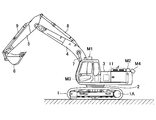
- FIG. 1 is a side view of an excavator according to an embodiment of the present invention.
- An upper swing body 3 is mounted on a lower traveling body 1 of the shovel shown in FIG.
- a boom 4 is attached to the upper swing body 3.
- An arm 5 is attached to the tip of the boom 4, and a bucket 6 is attached to the tip of the arm 5.
- the boom 4, the arm 5, and the bucket 6 as work elements constitute a drilling attachment that is an example of an attachment.
- the attachment may be another attachment such as a floor moat attachment, a leveling attachment, and a heel attachment.
- the boom 4, arm 5, and bucket 6 are hydraulically driven by a boom cylinder 7, an arm cylinder 8, and a bucket cylinder 9, respectively.
- the upper swing body 3 is provided with a cabin 10, and a power source such as an engine 11 is mounted thereon. Further, a communication device M1, a positioning device M2, a posture detection device M3, and an imaging device M4 are attached to the upper swing body 3.
- the communication device M1 is a device that controls communication between the excavator and the outside.
- the communication device M1 controls wireless communication between a GNSS (Global Navigation Satellite System) survey system and an excavator.
- GNSS Global Navigation Satellite System
- the communication device M1 acquires the terrain information of the work site when starting the excavator work at a frequency of once a day, for example.
- the GNSS survey system employs, for example, a network type RTK-GNSS positioning method.
- the positioning device M2 is a device that measures the position and orientation of the excavator.
- the positioning device M2 is a GNSS receiver that incorporates an electronic compass, and measures the latitude, longitude, and altitude of the location of the shovel and measures the orientation of the shovel.
- the direction of the excavator corresponds to, for example, the direction of the upper revolving unit 3 and the direction of the attachment, and is independent of the direction of the lower traveling unit 1.
- the lower traveling body 1 moves forward or backward according to the tilting direction of a traveling lever that is one of the operation devices 26 (see FIG. 3).
- the side on which the traveling hydraulic motor 1A (for left) and the traveling hydraulic motor 1B (for right, invisible) are arranged corresponds to the rear of the lower traveling body 1.
- the posture detection device M3 is a device that detects the posture of the attachment. In the present embodiment, the posture detection device M3 is a device that detects the posture of the excavation attachment.
- the imaging device M4 is a device that acquires an image around the excavator.
- the imaging device M4 is a camera attached to the upper swing body 3 of the excavator, and recognizes the distance to the ground around the excavator based on the captured image, and acquires terrain information on the work site.
- the imaging device M4 may be a stereo camera, a distance image camera, a three-dimensional laser scanner, or the like.
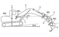
- FIG. 2 is a side view of the shovel showing an example of output contents of various sensors constituting the attitude detection device M3 mounted on the shovel of FIG.
- the attitude detection device M3 includes a boom angle sensor M3a, an arm angle sensor M3b, a bucket angle sensor M3c, and a vehicle body tilt sensor M3d.
- the boom angle sensor M3a is a sensor that acquires the boom angle ⁇ 1, and for example, a rotation angle sensor that detects the rotation angle of the boom foot pin, a stroke sensor that detects the stroke amount of the boom cylinder 7, and an inclination angle of the boom 4 Including an inclination (acceleration) sensor.
- the boom angle ⁇ 1 is an angle with respect to the horizontal line of the line segment connecting the boom foot pin position P1 and the arm connecting pin position P2 in the XZ plane.
- the arm angle sensor M3b is a sensor that acquires the arm angle ⁇ 2.
- a rotation angle sensor that detects the rotation angle of the arm connecting pin
- a stroke sensor that detects the stroke amount of the arm cylinder 8
- an inclination angle of the arm 5 are detected.
- the arm angle ⁇ 2 is an angle with respect to a horizontal line segment connecting the arm connecting pin position P2 and the bucket connecting pin position P3 in the XZ plane.
- the bucket angle sensor M3c is a sensor that acquires the bucket angle ⁇ 3.
- the rotation angle sensor that detects the rotation angle of the bucket connecting pin, the stroke sensor that detects the stroke amount of the bucket cylinder 9, and the inclination angle of the bucket 6 are detected.
- the bucket angle ⁇ 3 is an angle with respect to a horizontal line segment connecting the bucket connecting pin position P3 and the bucket toe position P4 in the XZ plane.
- the vehicle body inclination sensor M3d is a sensor that acquires an inclination angle ⁇ 4 around the Y-axis of the shovel and an inclination angle ⁇ 5 (not shown) around the X-axis of the shovel.
- a biaxial inclination (acceleration) sensor or the like is used. Including. Note that the XY plane in FIG. 2 is a horizontal plane.
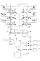
- FIG. 3 is a diagram showing a configuration example of a drive system mounted on the excavator of FIG. 1, and a mechanical power transmission line, a high-pressure hydraulic line, a pilot line, an electric control line, and a power line are respectively double lines and solid lines. , A broken line, a dotted line, and a one-dot chain line.
- the drive system of the excavator mainly includes an engine 11, a generator 12, main pumps 14L and 14R, a pilot pump 15, a control valve 17, an operation device 26, an operation content detection device 29, a controller 30, a battery 70, an electrical component 72, A power feeding device 74 and a display device 76 are included.
- the engine 11 is, for example, a diesel engine that operates so as to maintain a predetermined rotational speed.
- the output shaft of the engine 11 is connected to the input shafts of the generator 12, the main pumps 14L and 14R, and the pilot pump 15.
- the generator 12 is a device that generates electric power by rotating using the driving force of the engine 11, and supplies electric energy to the controller 30, the battery 70, the electrical component 72, the power feeding device 74, the display device 76, and the like.
- the main pumps 14L and 14R are devices for supplying hydraulic oil to the control valve 17 via a high-pressure hydraulic line, and are, for example, swash plate type variable displacement hydraulic pumps.
- the pilot pump 15 is a device for supplying hydraulic oil to various hydraulic control devices such as the operation device 26 via the pilot line 25, and is, for example, a fixed displacement hydraulic pump.
- the control valve 17 is a hydraulic control device that controls the hydraulic system in the excavator. Specifically, the control valve 17 includes flow rate control valves 171 to 176 that control the flow of hydraulic oil discharged from the main pumps 14L and 14R.
- the control valve 17 is connected to the boom cylinder 7, the arm cylinder 8, the bucket cylinder 9, the traveling hydraulic motor 1A (for left), the traveling hydraulic motor 1B (for right), and the turning hydraulic pressure through the flow control valves 171 to 176.
- the hydraulic oil discharged from the main pumps 14L and 14R is selectively supplied to one or a plurality of motors 2A.
- the boom cylinder 7, the arm cylinder 8, the bucket cylinder 9, the traveling hydraulic motor 1A (for left), the traveling hydraulic motor 1B (for right), and the turning hydraulic motor 2A are collectively referred to as “hydraulic actuator”. Called.
- the operating device 26 is a device used by an operator for operating the hydraulic actuator.
- the operating device 26 supplies the hydraulic oil discharged from the pilot pump 15 through the pilot line 25 to the pilot ports of the flow control valves corresponding to the hydraulic actuators.
- the hydraulic oil pressure (pilot pressure) supplied to each pilot port is a pressure corresponding to the operation direction and operation amount of a lever or pedal (not shown) of the operation device 26 corresponding to each hydraulic actuator. It is.
- the operation content detection device 29 is a device that detects the operation content of the operator using the operation device 26.
- the operation content detection device 29 detects the operation direction and the operation amount of the lever or pedal of the operation device 26 corresponding to each of the hydraulic actuators in the form of pressure, and outputs the detected value to the controller 30.
- the operation content of the operation device 26 may be derived using the output of a sensor other than the pressure sensor such as a potentiometer.
- the controller 30 is a control device for controlling the excavator, and includes, for example, a computer including a CPU, a RAM, a nonvolatile memory, and the like. Further, the controller 30 reads programs corresponding to various functional elements from the ROM, loads them into the RAM, and causes the CPU to execute processes corresponding to the various functional elements.
- the battery 70 is a device that stores electrical energy, and is charged with, for example, power generated by the generator 12. Further, the electric energy of the battery 70 is supplied to the controller 30, the electrical component 72, the power feeding device 74, the display device 76, and the like.
- the electrical component 72 is an electrical load mounted on the excavator, and includes, for example, an audio output device, a lighting device, and the like.
- the power feeding device 74 is a device for supplying electric energy to an external electric device, and includes, for example, a plug receptacle that receives an insertion plug of the external electric device.
- External electric equipment includes a multi-copter (drone) for aerial photography.
- the operator can charge the battery of the aerial shooting multicopter by inserting the plug of the power cable extending from the battery of the aerial shooting multicopter into the plug receiver of the power feeding device 74.
- the display device 76 is a device that displays various types of information, and is, for example, an in-vehicle display installed in the cabin 10.
- the display device 76 is connected to the imaging device M4 and can display an image around the excavator acquired by the imaging device M4.
- the main pumps 14L and 14R driven by the engine 11 circulate the hydraulic oil to the hydraulic oil tank through the center bypass pipelines 40L and 40R, respectively.
- the center bypass conduit 40L is a high-pressure hydraulic line that passes through the flow control valves 171, 173, and 175 disposed in the control valve 17.
- the center bypass conduit 40 ⁇ / b> R is a high-pressure hydraulic line that passes through the flow control valves 172, 174, and 176 disposed in the control valve 17.
- the flow control valves 171, 172, and 173 are spool valves that control the flow rate and flow direction of hydraulic fluid flowing into and out of the traveling hydraulic motor 1A (for left), the traveling hydraulic motor 1B (for right), and the turning hydraulic motor 2A. It is.
- the flow control valves 174, 175, and 176 are spool valves that control the flow rate and flow direction of the hydraulic oil flowing into and out of the bucket cylinder 9, the arm cylinder 8, and the boom cylinder 7.
- a regenerated oil passage 175a (see FIG. 6A) is formed inside the flow control valve 175.
- a regeneration release valve 50 is attached between the flow control valve 175 and the hydraulic oil tank.
- FIG. 4 is a functional block diagram illustrating a configuration example of the controller 30.
- the controller 30 receives the outputs of the communication device M1, the positioning device M2, the attitude detection device M3, and the imaging device M4, executes various calculations, and sends control commands according to the calculation results to the control target (for example, Engine 11, main pumps 14L, 14R, control valve 17, regeneration release valve 50, etc.).
- the control target for example, Engine 11, main pumps 14L, 14R, control valve 17, regeneration release valve 50, etc.
- the controller 30 mainly includes a terrain database update unit 31, a position coordinate update unit 32, a ground shape information acquisition unit 33, and an excavation control unit 34.
- the terrain database update unit 31 is a functional element that updates the terrain database that is systematically stored so that the terrain information of the work site can be referred to.
- the terrain database update unit 31 updates the terrain database by acquiring the terrain information on the work site through the communication device M1 when the excavator is activated, for example.
- the topographic database is stored in a nonvolatile memory or the like. Further, the terrain information on the work site is described by, for example, a three-dimensional terrain model based on the world positioning system.
- the terrain database update unit 31 may update the terrain database using the output of the imaging device M4.
- the imaging device M4 may be independent from the excavator.
- the controller 30 may acquire the terrain information output from the imaging device M4 via the communication device M1.
- the imaging device M4 may be attached to an aerial imaging multicopter, a steel tower installed at a work site, or the like, and may acquire terrain information on the work site based on an image of the work site viewed from above. Further, when attached to the aerial imaging multicopter, the imaging device M4 captures an image of the work site as viewed from above at a frequency of about once per hour or in real time, and acquires terrain information of the work site. May be.
- the terrain database update unit 31 acquires, for example, the terrain information of the work site through the communication device M1 at a frequency of once a day, and the work site through the imaging device M4 at a frequency of once per hour or in real time.
- the terrain database may be updated by acquiring the terrain information.
- the terrain database update unit 31 uses the terrain information acquired through the communication device M1 and the terrain information acquired through the imaging device M4, the terrain database update unit 31 passes through the imaging device M4 to correct the terrain information acquired through the communication device M1.
- the acquired terrain information may be used.
- the terrain database update unit 31 may correct the terrain information at a cycle (interval) longer than the cycle (interval) at which the communication device M1 acquires the terrain information.
- the position coordinate update unit 32 is a functional element that updates the coordinates and orientation representing the current position of the excavator.
- the position coordinate updating unit 32 acquires the position coordinates and orientation of the shovel in the world positioning system based on the output of the positioning device M2, and the coordinates indicating the current position of the shovel stored in the nonvolatile memory or the like Update orientation data.
- the position coordinate update unit 32 may update the coordinates and orientation representing the current position of the shovel using the output of the imaging device M4.
- the position coordinate updating unit 32 may update the data regarding the coordinates and the direction indicating the current position of the shovel in real time by using the output of the positioning device M2 and the output of the imaging device M4 together.
- the position coordinate updating unit 32 may update data regarding the coordinates and orientation representing the current position of the shovel in real time based only on the output of the imaging device M4.
- the ground shape information acquisition unit 33 is a functional element that acquires information on the current shape of the work target ground.
- the ground shape information acquisition unit 33 detects the terrain information updated by the terrain database update unit 31, the coordinates and orientation indicating the current position of the excavator updated by the position coordinate update unit 32, and the posture detection device M3. Information on the current shape of the excavation target ground is acquired based on the past transition of the attitude of the excavation attachment.
- FIG. 5 is a conceptual diagram of information on the current shape of the excavation target ground acquired by the ground shape information acquisition unit 33.
- a plurality of bucket shapes indicated by broken lines in FIG. 5 represent the trajectory of the bucket 6 during the previous excavation operation.
- the trajectory of the bucket 6 is derived from the posture transition of the excavation attachment detected by the posture detection device M3 in the past.
- 5 represents the current cross-sectional shape of the excavation target ground grasped by the ground shape information acquisition unit 33
- the thick dotted line represents the previous excavation operation grasped by the ground shape information acquisition unit 33.
- each block extending in the Z-axis direction indicated by a one-dot chain line in FIG. 5 represents each element of the three-dimensional terrain model.
- each element is represented by a model having an upper surface of a unit area parallel to the XY plane and an infinite length in the ⁇ Z direction.
- the three-dimensional terrain model may be represented by a three-dimensional mesh model.
- the excavation control unit 34 is a functional element that controls the excavation attachment.
- the excavation control unit 34 controls the excavation attachment based on information regarding the current shape of the excavation target ground acquired by the ground shape information acquisition unit 33.
- the excavation control unit 34 includes information on the current posture of the excavation attachment detected by the posture detection device M3 and the current shape of the excavation target ground acquired by the ground shape information acquisition unit 33 (the previous excavation operation).
- the excavation state is determined based on the information calculated from the attitude information at the time. For example, the excavation control unit 34 determines whether the tip of the bucket 6 is in contact with the excavation target ground. When it is determined that the tip of the bucket 6 is in contact with the ground to be excavated, the control mode is switched from the “ground surface mode” to the “underground mode”.
- the excavation control unit 34 accurately determines whether the bucket 6 is in contact with the excavation target ground in order to start excavation smoothly, and then uses the high-pressure hydraulic oil discharged from the main pumps 14L and 14R as an arm cylinder. 8 to the bottom oil chamber.
- the excavation control unit 34 When the control target is, for example, the regeneration cancellation valve 50, the excavation control unit 34 outputs a control command to the regeneration cancellation valve 50 to open the opening when the tip of the bucket 6 contacts the excavation target ground. Increase area. Note that “when contacting” includes “immediately before contacting”, and the excavation control unit 34 preferably outputs a control command to the regeneration release valve 50 immediately before the tip of the bucket 6 contacts the excavation target ground. Increase the opening area. Furthermore, you may control a excavation attachment based on the sediment density information input previously. For example, the opening area may be increased as the earth and sand density is increased.
- the excavation control unit 34 may control the engine 11, the main pumps 14L, 14R, and the like.
- the control mode is switched from the “ground surface mode” to the “underground mode”.
- the output horsepower of the excavation attachment is increased by increasing the rotational speed command of the engine 11 or changing the tilt angle of the swash plate of the main pumps 14L and 14R.
- the driving force of the excavation attachment can be increased when working in the “underground mode”.
- the output horsepower can be reduced to improve fuel efficiency.
- the excavation control unit 34 may execute the control of each control target described above alone or in combination. Also, this control may be executed until the current shape of the excavation target ground becomes the target shape. For example, it may be executed until the depth of the excavation target ground reaches a preset target surface depth. When the depth of the excavation target ground reaches the depth of the target surface, excavation deeper than that may be restricted.
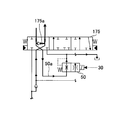
- FIG. 6A to 6C are diagrams showing examples of the configuration of the regeneration oil passage 175a and the regeneration cancellation valve 50.
- FIG. 6A is an enlarged view of a portion including the flow control valve 175 and the regeneration release valve 50 in the control valve 17 shown in FIG. 6B shows the flow of hydraulic oil when the opening area of the regeneration release valve 50 is minimized during the arm closing operation
- FIG. 6C shows the operation when the opening area of the regeneration cancellation valve 50 is maximized during the arm closing operation. The oil flow is shown.
- the regeneration oil passage 175a is an oil passage through which hydraulic oil that flows out from the rod-side oil chamber of the arm cylinder 8 that is the contraction-side oil chamber during the arm closing operation flows (regenerates) into the bottom-side oil chamber that is the extension-side oil chamber. . Further, the regenerative oil passage 175a includes a check valve that prevents the flow of hydraulic oil from the bottom side oil chamber to the rod side oil chamber. Note that the regenerated oil passage 175a may be formed outside the flow control valve 175.
- the regeneration release valve 50 is a valve that adjusts the flow rate of the hydraulic oil that flows out from the rod side oil chamber of the arm cylinder 8 and flows to the hydraulic oil tank.
- the regeneration release valve 50 is an electromagnetic valve that operates in response to a control command from the controller 30, and increases or decreases the flow area of the oil path 50a between the flow control valve 175 and the hydraulic oil tank. The flow rate of the hydraulic oil flowing through each of the oil passage 50a and the regenerated oil passage 175a is adjusted.
- the regeneration cancellation valve 50 reduces the flow area of the hydraulic oil flowing through the oil passage 50a by reducing the opening area in accordance with a control command from the controller 30, and the regeneration oil passage.
- the flow rate of the hydraulic oil flowing through 175a is increased.
- the regeneration release valve 50 can prevent the arm 5 from dropping due to its own weight when the excavation attachment is operated in the air.
- the regeneration release valve 50 increases its opening area in accordance with a control command from the controller 30, increases the flow rate of the working oil flowing through the oil passage 50a, and flows through the regeneration oil passage 175a. Reduce or eliminate hydraulic fluid flow. With this configuration, the regeneration release valve 50 reduces the digging force by generating a useless pressure loss in the oil passage 50a even when digging is being performed, that is, the digging attachment is in contact with the ground. Can be prevented.
- the regeneration release valve 50 may be installed between the rod side oil chamber of the arm cylinder 8 and the flow control valve 175.
- FIG. 7 is a flowchart showing the flow of the opening area adjustment process.
- the controller 30 repeatedly performs the opening area adjustment process at a predetermined control period during the excavator operation.
- the controller 30 determines whether an arm closing operation has been performed (step S1). In this embodiment, the controller 30 determines whether the arm operation lever is operated in the closing direction based on the output of the operation content detection device 29.
- step S1 If it is determined that the arm closing operation has not been performed (NO in step S1), the controller 30 ends the current opening area adjustment process.
- the controller 30 determines whether the excavation attachment is in contact with the ground (step S2). In the present embodiment, the controller 30 generates a bucket based on the current position of the toe of the bucket 6 derived from the output of the attitude detection device M3 and information on the current shape of the excavation target ground acquired by the ground shape information acquisition unit 33. It is determined whether 6 toes are in contact with the ground.
- step S3 when it determines with the excavation attachment and the ground contacting (YES of step S2), the controller 30 increases the opening area of the regeneration cancellation
- the controller 30 determines that the toe of the bucket 6 is in contact with the ground, if the opening area of the regeneration release valve 50 is less than a predetermined value, the controller 30 increases the opening area to a predetermined value.
- step S4 when it determines with the excavation attachment and the ground not contacting (NO of step S2), the controller 30 reduces the opening area of the regeneration cancellation
- the controller 30 determines that the tip of the bucket 6 is not in contact with the ground, if the opening area of the regeneration release valve 50 is larger than a predetermined value, the opening area of the regeneration release valve 50 is reduced to a predetermined value. Reduce.
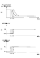
- FIG. 8A shows the temporal transition of the pressure in the rod side oil chamber of the arm cylinder 8.
- 8B shows the time transition of the ground contact flag
- FIG. 8C shows the time transition of the opening area of the regeneration release valve 50.
- 8A to 8C have a common time axis (horizontal axis).
- the ground contact flag represents a determination result of presence / absence of contact between the excavation attachment and the ground by the controller 30. Specifically, the value “OFF” of the ground contact flag represents a state that is determined as “no contact” by the controller 30, and the value “ON” of the ground contact flag is determined as “contact” by the controller 30.
- transition indicated by the solid line in FIG. 8 represents a transition when the determination of actual contact and “contact” is made at the same time.
- transition indicated by the broken line in FIG. 8 represents the transition when the determination of “contact” is performed before the actual contact, and the transition indicated by the one-dot chain line in FIG. This represents a transition when the determination is made after the actual contact.
- the ground contact flag is changed from the value “OFF” at time t1, as indicated by a broken line in FIG. 8B. It can be switched to “ON”. In this embodiment, actual contact occurs at time t2.
- the controller 30 increases the opening area of the regeneration cancellation valve 50. Therefore, the opening area of the regeneration cancellation valve 50 is adjusted from the value An to the value Aw (> An) at time t1, as indicated by a broken line in FIG.
- the value An is an opening area preset as an optimum value when the arm 5 is operated in the air
- the value Aw is an opening area preset as an optimum value when the arm 5 is operated during excavation. It is.
- the pressure in the rod-side oil chamber of the arm cylinder 8 begins to decrease at time t1, as indicated by the broken line in FIG. 8A, and continues to decrease until actual contact occurs. This is because the arm 5 falls by its own weight. Then, after actual contact occurs at time t2, it starts to increase (between time t2 and time t3) and thereafter increases to a value corresponding to the excavation reaction force as the work reaction force.
- the controller 30 determines that there is “contact” before the actual contact, the pressure in the oil chamber on the rod side of the arm cylinder 8 is suddenly reduced temporarily, which may cause cavitation. There is.
- the opening area of the regeneration release valve 50 remains small at the time t2 when the actual contact occurs, so the pressure in the rod side oil chamber is It will rise. Then, the ground contact flag is switched from the value “OFF” to the value “ON” at time t3, as indicated by the one-dot chain line in FIG. 8B. Therefore, the opening area of the regeneration cancellation valve 50 is adjusted from the value An to the value Aw at time t3, as indicated by a one-dot chain line in FIG. As a result, the pressure in the oil chamber on the rod side of the arm cylinder 8 starts to increase at time t2 when actual contact occurs, as indicated by the one-dot chain line in FIG.
- the controller 30 determines that “contact is present” after the actual contact, the pressure in the oil chamber on the rod side of the arm cylinder 8 is temporarily increased. It stabilizes and reduces work efficiency.
- the controller 30 sets the excavation attachment to the excavation target ground based on the current attitude of the excavation attachment detected by the attitude detection device M3 and information on the current shape of the excavation target ground acquired by the ground shape information acquisition unit 33. Determine if they are touching. This is because the determination of “contact” is performed simultaneously with the actual contact.
- the ground contact flag is switched from the value “OFF” to the value “ON” at time t2, as indicated by the solid line in FIG. Therefore, the opening area of the regeneration cancellation valve 50 is adjusted from the value An to the value Aw at time t2, as indicated by the solid line in FIG.
- the pressure in the rod side oil chamber of the arm cylinder 8 starts to decrease at time t2 when actual contact occurs, and then decreases to a value corresponding to the excavation reaction force. To do. It does not decrease temporarily before the actual contact occurs, and does not increase under the influence of the pressure loss at the regeneration release valve 50 after the actual contact occurs.
- the controller 30 acquires information on the current shape of the work target ground based on the transition of the posture of the attachment detected by the posture detection device M3. Then, the attachment is controlled based on the acquired information on the current shape of the work target ground.
- the controller 30 adjusts the opening area of the regeneration release valve 50 based on the current posture of the excavation attachment and the current shape of the excavation target ground. Specifically, the opening area of the regeneration release valve 50 is adjusted based on the current position of the toe of the bucket 6 and the current shape of the excavation target ground.
- the controller 30 can more accurately determine the presence / absence of contact than the case where the presence / absence of contact between the toe of the bucket 6 and the excavation target ground is determined based on a change in arm cylinder pressure or the like, thereby suppressing erroneous determination. it can. Further, operability and work efficiency can be improved by suppressing erroneous determination of the presence or absence of contact.
- the pressure loss generated at the regeneration release valve 50 to prevent the arm 5 from dropping its weight can be reduced or eliminated. It is possible to prevent the force required for excavation from increasing by the amount of loss. Moreover, it is possible to prevent the arm 5 from falling by its own weight before contact with the ground, and to prevent cavitation.
- the controller 30 may adjust the opening area of the regeneration release valve (not shown) for the boom cylinder 7 in the same manner as adjusting the opening area of the regeneration release valve 50 for the arm cylinder 8.
- the opening area of the regeneration release valve (not shown) for 9 may be adjusted.
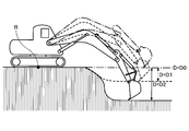
- FIG. 9 is a diagram showing the relationship between the depth of the excavation target ground and the reference plane.
- the reference plane is a plane serving as a reference for determining the depth of the excavation target ground.
- the reference plane is a horizontal plane on which the center point R of the shovel is located, and the center point R is the intersection of the shovel turning shaft and the ground contact surface of the lower traveling body 1.
- the excavation attachment indicated by the one-dot chain line in FIG. 9 represents the posture of the excavation attachment when excavating the ground to be excavated at the same depth as the reference plane indicated by the one-dot chain line.
- the depth D of the excavation target ground is derived based on information on the current shape of the excavation target ground acquired by the ground shape information acquisition unit 33 (information calculated from the posture information at the previous excavation operation). . Further, the depth D of the excavation target ground may be derived based on the current posture of the excavation attachment detected by the posture detection device M3.
- the excavation attachment indicated by the broken line in FIG. 9 represents the posture of the excavation attachment when excavating the excavation target ground indicated by the broken line.
- the depth D of the excavation target ground is represented by a depth D1 (> D0).
- the excavation attachment indicated by the solid line in FIG. 9 represents the attitude of the excavation attachment when excavating the excavation target ground indicated by the solid line.
- the depth D of the excavation target ground is represented by the depth D2 (> D1).
- the excavation target ground may be located at a position higher than the reference plane.
- the depth D of the excavation target ground may be expressed as a negative value.
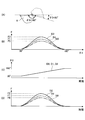
- FIG. 10 is a diagram showing the relationship between the bucket angle ⁇ 3, the excavation reaction force F, and the depth D of the excavation target ground.
- FIG. 10A shows the transition of the posture of the bucket 6 when the bucket 6 is closed from the bucket angle 30 ° to the bucket angle 180 °.
- the bucket 6 indicated by a broken line in FIG. 10A represents the attitude when the bucket angle is 30 °
- the bucket 6 indicated by the solid line in FIG. 10A represents the attitude when the bucket angle is 180 °.
- FIG. 10B shows an example of the contents of a correspondence table that stores in advance the correspondence between the depth D of the excavation target ground and the transition or peak value of the excavation reaction force F when a predetermined bucket closing operation is performed. . Specifically, FIG. 10B shows the transition of the excavation reaction force F with respect to the bucket angle ⁇ 3 when the bucket 6 is closed from the bucket angle 30 ° to the bucket angle 180 °.
- the correspondence table is a data table generated based on analysis of actual measurement data, and is registered in advance in a nonvolatile memory, for example.
- FIG. 10C shows the temporal transition of the bucket angle ⁇ 3
- FIG. 10D shows the temporal transition of the excavation reaction force F calculated using the correspondence table of FIG. 10B. Note that the time axes (horizontal axes) in FIGS. 10C and 10D are common.
- transition indicated by the alternate long and short dash line in FIGS. 10B and 10D represents the transition when the depth D of the excavation target ground is the depth D0.
- a transition indicated by a broken line represents a transition when the depth D of the excavation target ground is the depth D1
- a transition indicated by a solid line represents a transition when the depth D of the excavation target ground is the depth D2.
- FIGS. 10 (A) and 10 (C) When a bucket closing operation from a bucket angle of 30 ° to 180 ° as shown in FIGS. 10 (A) and 10 (C) is performed, the excavation reaction force F is as shown in FIG. 10 (B). After the angle ⁇ 3 has increased to a certain angle (for example, 100 °), the angle ⁇ 3 starts to decrease, and reaches zero when the bucket angle ⁇ 3 reaches 180 °. This tendency is the same regardless of the depth D of the excavation target ground. However, the peak value of the excavation reaction force F changes according to the change in the depth D of the excavation target ground.
- FIG. 10B and FIG. 10D illustrate, as an example, a tendency that the peak value of the excavation reaction force F increases as the depth D of the excavation target ground increases.
- the excavation control unit 34 of the controller 30 derives the current depth D of the excavation target ground based on the information regarding the current shape of the excavation target ground acquired by the ground shape information acquisition unit 33. Then, the excavation control unit 34 estimates the peak value of the excavation reaction force F when a predetermined bucket closing operation is performed according to the current depth D of the excavation target ground. Thereafter, the excavation control unit 34 determines whether the estimated peak value of the excavation reaction force F exceeds a predetermined value. And when it determines with exceeding, the motion of a digging attachment is controlled so that the peak value may not exceed a predetermined value. This is to prevent the excavation reaction force F from becoming excessively large and the movement of the excavation attachment to become unstable.
- the excavation control unit 34 automatically raises the boom 4 during the bucket closing operation so that the peak value of the excavation reaction force F does not exceed a predetermined value regardless of whether or not the operator raises the boom. To do.
- the excavation control unit 34 automatically raises the boom 4 at an increase rate (the rotation angle of the boom 4 per unit time) that the operator does not notice. Therefore, the excavation control unit 34 can smooth the movement of the excavation attachment without notifying the operator that the boom 4 has automatically raised, and can improve the operational feeling.
- the control target of the excavation control unit 34 is not the regeneration release valve 50 but the flow rate control valve 176.
- the excavation control unit 34 outputs a control command to an electromagnetic valve (not shown) that increases or decreases the pilot pressure of the flow control valve 176 to automatically move the flow control valve 176.
- this control may be executed until the current shape of the excavation target ground becomes the target shape. For example, it may be executed until the depth of the excavation target ground reaches a preset target surface depth. When the depth of the excavation target ground reaches the depth of the target surface, excavation deeper than that may be restricted.
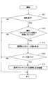
- FIG. 11 shows a flow of a process in which the controller 30 automatically adjusts the attitude of the excavation attachment so that the peak value of the excavation reaction force F does not exceed a predetermined value (hereinafter referred to as “attitude automatic adjustment process”). It is a flowchart. The controller 30 repeatedly executes this automatic posture adjustment processing at a predetermined control cycle during operation of the excavator.
- the controller 30 determines whether an excavation operation has been performed (step S11). In the present embodiment, the controller 30 determines whether at least one of the boom operation, the arm operation, and the bucket operation has been performed based on the output of the operation content detection device 29.
- the controller 30 determines whether the excavation attachment and the ground are contacting (step S12). In the present embodiment, the controller 30 generates a bucket based on the current position of the toe of the bucket 6 derived from the output of the attitude detection device M3 and information on the current shape of the excavation target ground acquired by the ground shape information acquisition unit 33. It is determined whether 6 toes are in contact with the ground.
- the controller 30 estimates the peak value of the excavation reaction force F (step S13).
- the controller 30 derives the current depth D of the excavation target ground based on the information related to the current shape of the excavation target ground acquired by the ground shape information acquisition unit 33. Then, the controller 30 estimates the peak value of the excavation reaction force F when a predetermined bucket closing operation is performed according to the current depth D of the excavation target ground. Specifically, the controller 30 derives a peak value of the excavation reaction force F corresponding to the current depth D of the excavation target ground with reference to a correspondence table as shown in FIG.
- the controller 30 may calculate the peak value of the excavation reaction force F when a predetermined bucket closing operation is performed based on the current depth D of the excavation target ground in real time. Moreover, the controller 30 may consider earth and sand density etc., when calculating the peak value.
- the sediment density may be a value input by an operator through an in-vehicle input device (not shown), or may be a value automatically calculated based on outputs of various sensors such as a cylinder pressure sensor. .
- the controller 30 determines whether or not the estimated peak value of the excavation reaction force F exceeds a predetermined value Fth (step S14).
- the controller 30 automatically adjusts the attitude of the excavation attachment during the bucket closing operation (step S15).
- the controller 30 automatically raises the boom 4 during the bucket closing operation regardless of whether or not the operator raises the boom.
- the boom 4 is automatically raised with a predetermined operation pattern corresponding to the change in the bucket angle ⁇ 3.
- the controller 30 determines that the excavation operation is not performed (NO in step S11), determines that the excavation attachment and the ground are not in contact (NO in step S12), or has a predetermined peak value. If it is determined that the value is less than or equal to the value Fth (NO in step S14), the current automatic posture adjustment process is terminated without automatically adjusting the posture of the excavation attachment.
- the controller 30 acquires information on the current shape of the work target ground based on the transition of the posture of the attachment detected by the posture detection device M3. Then, the attachment is controlled based on the acquired information on the current shape of the work target ground.
- the controller 30 can prevent the peak value of the excavation reaction force F from exceeding the predetermined value Fth during the bucket closing operation. Therefore, it is possible to prevent the excavation reaction force F from excessively increasing and the movement of the excavation attachment to become unstable, and improve the operability and work efficiency of the excavator. Further, the controller 30 can achieve the same effect even in work other than excavation work such as floor excavation work and leveling work by using the predetermined value Fth set to be low.
- the controller 30 excavates based on the current posture of the excavation attachment detected by the posture detection device M3 and the information related to the current shape of the excavation target ground acquired by the ground shape information acquisition unit 33. It is determined whether the attachment is in contact with the excavation target ground. And when it determines with contacting, a control command is output with respect to the reproduction
- the peak value of the excavation reaction force F when a predetermined bucket closing operation is performed is estimated, and when the estimated peak value exceeds the predetermined value Fth, the boom 4 is It is automatically raised so that the actual peak value is less than or equal to the predetermined value Fth.
- the controller 30 may increase the drive force of the attachment (for example, excavation force by the excavation attachment) when it is determined that the controller 30 is in contact.
- the controller 30 may increase the rotation speed of the engine 11 or increase the discharge amount of the main pumps 14L and 14R.
- the control object of the excavation control unit 34 is not the regeneration release valve 50 but the regulator of the engine 11 or the main pumps 14L and 14R.
- controller 30 automatically raises the boom 4 when determining that the peak value of the excavation reaction force F exceeds the predetermined value Fth even in the case of remote operation or automatic excavation operation (unmanned operation) of the excavator. You may let them. This is because the excavation reaction force F is reduced to continue smooth excavation work.
- Regenerative release valve 50a Oil passage 70 ... Battery 72 ... Electrical equipment 74 ... Power supply device 76 ... Display device 171-176 ... Flow control valve 175a ... Reclaimed oil path M1 ... Communication device M2 ... Positioning device M3 ... Attitude detection device M3a ... Boom angle sensor M3b ... Arm angle sensor M3c ... Bucket angle sensor M3d ... Car body tilt sensor M4 ... Imaging device
Landscapes
- Engineering & Computer Science (AREA)
- Mining & Mineral Resources (AREA)
- Civil Engineering (AREA)
- General Engineering & Computer Science (AREA)
- Structural Engineering (AREA)
- Mechanical Engineering (AREA)
- Physics & Mathematics (AREA)
- Fluid Mechanics (AREA)
- Operation Control Of Excavators (AREA)
- Component Parts Of Construction Machinery (AREA)
- Fluid-Pressure Circuits (AREA)
Abstract
Priority Applications (9)
| Application Number | Priority Date | Filing Date | Title |
|---|---|---|---|
| JP2016529413A JP6442502B2 (ja) | 2014-06-20 | 2015-06-17 | ショベル及びその制御方法 |
| EP15809022.5A EP3159455B1 (fr) | 2014-06-20 | 2015-06-17 | Pelle, et procédé de commande de celle-ci |
| EP18181903.8A EP3418455B1 (fr) | 2014-06-20 | 2015-06-17 | Pelleteuse et son procédé de commande |
| KR1020167035676A KR102389935B1 (ko) | 2014-06-20 | 2015-06-17 | 쇼벨 및 그 제어방법 |
| CN201580033429.3A CN106661867B (zh) | 2014-06-20 | 2015-06-17 | 挖土机及其控制方法 |
| KR1020227013033A KR102528572B1 (ko) | 2014-06-20 | 2015-06-17 | 쇼벨 및 그 제어방법 |
| US15/382,891 US10081928B2 (en) | 2014-06-20 | 2016-12-19 | Shovel and control method thereof |
| US16/108,681 US10968597B2 (en) | 2014-06-20 | 2018-08-22 | Shovel and control method thereof |
| US17/204,140 US20210198865A1 (en) | 2014-06-20 | 2021-03-17 | Shovel and control method thereof |
Applications Claiming Priority (2)
| Application Number | Priority Date | Filing Date | Title |
|---|---|---|---|
| JP2014-127672 | 2014-06-20 | ||
| JP2014127672 | 2014-06-20 |
Related Child Applications (1)
| Application Number | Title | Priority Date | Filing Date |
|---|---|---|---|
| US15/382,891 Continuation US10081928B2 (en) | 2014-06-20 | 2016-12-19 | Shovel and control method thereof |
Publications (1)
| Publication Number | Publication Date |
|---|---|
| WO2015194601A1 true WO2015194601A1 (fr) | 2015-12-23 |
Family
ID=54935581
Family Applications (1)
| Application Number | Title | Priority Date | Filing Date |
|---|---|---|---|
| PCT/JP2015/067505 WO2015194601A1 (fr) | 2014-06-20 | 2015-06-17 | Pelle, et procédé de commande de celle-ci |
Country Status (6)
| Country | Link |
|---|---|
| US (3) | US10081928B2 (fr) |
| EP (2) | EP3159455B1 (fr) |
| JP (7) | JP6442502B2 (fr) |
| KR (2) | KR102389935B1 (fr) |
| CN (2) | CN112359892A (fr) |
| WO (1) | WO2015194601A1 (fr) |
Cited By (13)
| Publication number | Priority date | Publication date | Assignee | Title |
|---|---|---|---|---|
| WO2017115879A1 (fr) * | 2017-01-13 | 2017-07-06 | 株式会社小松製作所 | Système de commande de machine de chantier, et procédé de commande de machine de chantier |
| WO2017115810A1 (fr) * | 2015-12-28 | 2017-07-06 | 住友建機株式会社 | Pelle |
| WO2017131194A1 (fr) * | 2016-01-29 | 2017-08-03 | 住友建機株式会社 | Excavatrice et corps volant autonome pour voler autour d'une excavatrice |
| WO2017131189A1 (fr) * | 2016-01-28 | 2017-08-03 | 住友建機株式会社 | Pelle |
| WO2017184038A1 (fr) | 2016-04-19 | 2017-10-26 | Cpac Systems Ab | Unité de commande dans une machine de travail pour identifier l'actionnement humain de dispositif |
| JP2017223096A (ja) * | 2016-06-17 | 2017-12-21 | 住友重機械工業株式会社 | ショベル |
| JP2018003516A (ja) * | 2016-07-06 | 2018-01-11 | 日立建機株式会社 | 作業機械 |
| WO2018051511A1 (fr) * | 2016-09-16 | 2018-03-22 | 日立建機株式会社 | Engin de chantier |
| WO2019009341A1 (fr) * | 2017-07-05 | 2019-01-10 | 住友重機械工業株式会社 | Pelle |
| WO2019058695A1 (fr) * | 2017-09-19 | 2019-03-28 | 日立建機株式会社 | Machine de travail |
| JP2019173867A (ja) * | 2018-03-28 | 2019-10-10 | 株式会社クボタ | 作業機の油圧システム |
| JP2020020154A (ja) * | 2018-07-31 | 2020-02-06 | 株式会社小松製作所 | 作業機械 |
| US10927528B2 (en) | 2015-09-15 | 2021-02-23 | Sumitomo(S.H.I.) Construction Machinery Co., Ltd. | Shovel |
Families Citing this family (24)
| Publication number | Priority date | Publication date | Assignee | Title |
|---|---|---|---|---|
| CN108138459B (zh) * | 2015-09-16 | 2021-05-11 | 住友重机械工业株式会社 | 挖土机 |
| JP6545609B2 (ja) * | 2015-12-04 | 2019-07-17 | 日立建機株式会社 | 油圧建設機械の制御装置 |
| KR102570491B1 (ko) * | 2015-12-28 | 2023-08-23 | 스미토모 겐키 가부시키가이샤 | 쇼벨 |
| JP6506205B2 (ja) * | 2016-03-31 | 2019-04-24 | 日立建機株式会社 | 建設機械 |
| KR102055222B1 (ko) * | 2017-06-30 | 2019-12-12 | 가부시키가이샤 고마쓰 세이사쿠쇼 | 촬상 장치, 건설 기계 및 촬상 시스템 |
| CN107447800A (zh) * | 2017-08-17 | 2017-12-08 | 山东省环科院环境工程有限公司 | 一种季节性河流污染底泥精确控制疏浚方法 |
| JP7200124B2 (ja) | 2017-11-10 | 2023-01-06 | 住友建機株式会社 | ショベル |
| CN111511993B (zh) * | 2017-12-12 | 2022-06-14 | 住友重机械工业株式会社 | 挖土机 |
| JP7141894B2 (ja) * | 2018-09-05 | 2022-09-26 | 日立建機株式会社 | 作業機械 |
| EP3922776A4 (fr) * | 2019-02-04 | 2022-03-30 | Sumitomo Heavy Industries, Ltd. | Excavatrice |
| WO2020203329A1 (fr) * | 2019-03-30 | 2020-10-08 | 住友建機株式会社 | Dispositif de traitement d'informations, procédé de traitement d'informations, programme et engin de chantier |
| JP7293933B2 (ja) * | 2019-07-17 | 2023-06-20 | コベルコ建機株式会社 | 作業機械および作業機械支援サーバ |
| CN110616770A (zh) * | 2019-09-23 | 2019-12-27 | 三一重机有限公司 | 斗杆油缸防吸空控制系统及控制方法及斗杆油缸及挖掘机 |
| JP7276046B2 (ja) * | 2019-09-26 | 2023-05-18 | コベルコ建機株式会社 | 作業機械の動作教示システム |
| JP7043471B2 (ja) * | 2019-09-30 | 2022-03-29 | 日立建機株式会社 | 作業機械 |
| EP4130393A4 (fr) * | 2020-03-24 | 2024-04-17 | Hitachi Construction Mach Co | Machine de travail |
| JP7372726B2 (ja) * | 2020-05-11 | 2023-11-01 | キャタピラー エス エー アール エル | 建設機械におけるブーム制御装置 |
| JP7481908B2 (ja) * | 2020-05-29 | 2024-05-13 | 株式会社小松製作所 | 掘削計画作成装置、作業機械および掘削計画作成方法 |
| US11236492B1 (en) * | 2020-08-25 | 2022-02-01 | Built Robotics Inc. | Graphical user interface for real-time management of an earth shaping vehicle |
| JP2022041683A (ja) | 2020-09-01 | 2022-03-11 | コベルコ建機株式会社 | アタッチメントの目標軌跡変更システム |
| CN112180928B (zh) * | 2020-09-30 | 2023-01-31 | 上海三一重机股份有限公司 | 挖掘机控制方法、挖掘机控制装置及挖掘机 |
| US20230417016A1 (en) * | 2020-12-21 | 2023-12-28 | Jdc Corporation | Construction Machine |
| CN112902919B (zh) * | 2021-01-21 | 2023-04-07 | 天津视通智能科技有限公司 | 管沟截面数据的测量方法、装置、设备和存储介质 |
| DE102022206976A1 (de) | 2022-07-08 | 2024-01-11 | Zf Friedrichshafen Ag | Verfahren zum Vermessen eines Arbeitsziels mittels eines Anbaugeräts |
Citations (5)
| Publication number | Priority date | Publication date | Assignee | Title |
|---|---|---|---|---|
| JP2005076448A (ja) * | 2003-08-28 | 2005-03-24 | Caterpillar Inc | 作業機械ディスプレイシステム |
| WO2011092837A1 (fr) * | 2010-01-29 | 2011-08-04 | 住友重機械工業株式会社 | Engin de chantier hybride |
| JP2013002058A (ja) * | 2011-06-13 | 2013-01-07 | Sumitomo Heavy Ind Ltd | ショベル |
| JP2013200023A (ja) * | 2012-03-26 | 2013-10-03 | Kyb Co Ltd | 建設機械の制御装置 |
| JP2014074315A (ja) * | 2012-10-05 | 2014-04-24 | Komatsu Ltd | 掘削機械の表示システム及び掘削機械 |
Family Cites Families (55)
| Publication number | Priority date | Publication date | Assignee | Title |
|---|---|---|---|---|
| AU571540B2 (en) | 1983-06-21 | 1988-04-21 | Solaja, N. | Combination grader/loader attachment |
| JPH0745738B2 (ja) | 1986-01-10 | 1995-05-17 | 株式会社小松製作所 | パワ−シヨベルの作業機制御装置 |
| US4807131A (en) * | 1987-04-28 | 1989-02-21 | Clegg Engineering, Inc. | Grading system |
| JPH01165827A (ja) * | 1987-12-21 | 1989-06-29 | Mitsui Constr Co Ltd | 圧気ケーソン用掘削機 |
| GB8904211D0 (en) * | 1989-02-24 | 1989-04-12 | Johnson David M | Curve computer |
| JPH0618253A (ja) * | 1992-06-30 | 1994-01-25 | Fujita Corp | 土砂の形状測定装置 |
| JP3255204B2 (ja) | 1993-07-22 | 2002-02-12 | 株式会社リコー | 光情報記録方法 |
| JPH0790879A (ja) | 1993-09-28 | 1995-04-04 | Komatsu Esuto:Kk | モータグレーダの自動ブレード昇降制御装置 |
| JP3024910B2 (ja) * | 1994-07-18 | 2000-03-27 | 新キャタピラー三菱株式会社 | 掘削用建設機械における自動掘削制御装置 |
| US5854988A (en) * | 1996-06-05 | 1998-12-29 | Topcon Laser Systems, Inc. | Method for controlling an excavator |
| US6047227A (en) * | 1996-11-19 | 2000-04-04 | Caterpillar Inc. | Method and apparatus for operating geography altering machinery relative to a work site |
| US5968103A (en) * | 1997-01-06 | 1999-10-19 | Caterpillar Inc. | System and method for automatic bucket loading using crowd factors |
| JP3802688B2 (ja) * | 1998-08-19 | 2006-07-26 | 日立建機株式会社 | 油圧ショベルの荷重計測装置 |
| US6363632B1 (en) * | 1998-10-09 | 2002-04-02 | Carnegie Mellon University | System for autonomous excavation and truck loading |
| US8478492B2 (en) * | 1998-11-27 | 2013-07-02 | Caterpillar Trimble Control Technologies, Inc. | Method and system for performing non-contact based determination of the position of an implement |
| JP2000242796A (ja) * | 1999-02-18 | 2000-09-08 | Ntt Data Corp | 画像データにおける変化領域抽出方法及び装置、記録媒体 |
| AU773818B2 (en) | 1999-11-30 | 2004-06-10 | Caterpillar Inc. | Method and apparatus for dynamically updating representations of a work site and a propagation model |
| JP3949330B2 (ja) | 1999-12-02 | 2007-07-25 | 日立建機株式会社 | 掘削機械の作業状態監視システム、作業状態表示装置及び記録媒体 |
| EP1278917B1 (fr) * | 2000-05-05 | 2009-11-11 | Leica Geosystems GR, LLC | Equipement de construction a guidage laser |
| US6453227B1 (en) * | 2000-12-16 | 2002-09-17 | Caterpillar Inc. | Method and apparatus for providing a display of a work machine at a work site |
| JP4671317B2 (ja) * | 2001-05-02 | 2011-04-13 | 株式会社小松製作所 | 地形形状計測装置およびガイダンス装置 |
| JP4727068B2 (ja) * | 2001-05-29 | 2011-07-20 | 株式会社トプコン | 施工監視システム、施工管理方法 |
| JP2005344482A (ja) * | 2004-06-07 | 2005-12-15 | Hitachi Constr Mach Co Ltd | 地表処理作業、土木工事及び地雷除去作業の管理支援システム |
| JP2006051893A (ja) * | 2004-08-12 | 2006-02-23 | Seiko Epson Corp | 位置・姿勢検出システム |
| JP4362452B2 (ja) | 2005-02-07 | 2009-11-11 | 青木あすなろ建設株式会社 | 作業機の施工支援システム |
| JP2007218405A (ja) | 2006-02-20 | 2007-08-30 | Ishikawajima Constr Mach Co | 建設機械の油圧回路 |
| JP4606365B2 (ja) | 2006-03-29 | 2011-01-05 | 株式会社クボタ | ローダ |
| US7734398B2 (en) * | 2006-07-31 | 2010-06-08 | Caterpillar Inc. | System for automated excavation contour control |
| JP2008144379A (ja) | 2006-12-06 | 2008-06-26 | Shin Caterpillar Mitsubishi Ltd | 遠隔操縦作業機の画像処理システム |
| US7865285B2 (en) * | 2006-12-27 | 2011-01-04 | Caterpillar Inc | Machine control system and method |
| JP2010174574A (ja) | 2009-01-30 | 2010-08-12 | Caterpillar Japan Ltd | 作業機械 |
| US8205820B2 (en) * | 2009-02-03 | 2012-06-26 | Honeywell International Inc. | Transforming unmanned aerial-to-ground vehicle |
| JP5135274B2 (ja) | 2009-03-26 | 2013-02-06 | 住友建機株式会社 | 建設機械用油圧制御回路 |
| JP5118116B2 (ja) * | 2009-11-11 | 2013-01-16 | コベルコ建機株式会社 | 建設機械 |
| JP2011220356A (ja) | 2010-04-02 | 2011-11-04 | Hitachi Constr Mach Co Ltd | 建設機械の油圧制御装置 |
| JP5519414B2 (ja) * | 2010-06-03 | 2014-06-11 | 住友重機械工業株式会社 | 建設機械 |
| KR20120004132A (ko) * | 2010-07-06 | 2012-01-12 | 전자부품연구원 | 굴삭기 자동화 시스템 및 그 통합 관리 방법 |
| JP5202667B2 (ja) | 2011-02-22 | 2013-06-05 | 株式会社小松製作所 | 油圧ショベルの位置誘導システム及びその制御方法 |
| JP2012203677A (ja) | 2011-03-25 | 2012-10-22 | Penta Ocean Construction Co Ltd | 安全管理システム |
| EP2511658A1 (fr) * | 2011-04-14 | 2012-10-17 | Hexagon Technology Center GmbH | Système de mesure et procédé de détermination de nouveau point |
| WO2012165614A1 (fr) | 2011-06-02 | 2012-12-06 | 川崎重工業株式会社 | Chambre de combustion de turbine à gaz |
| JP5802476B2 (ja) * | 2011-08-09 | 2015-10-28 | 株式会社トプコン | 建設機械制御システム |
| US8768583B2 (en) * | 2012-03-29 | 2014-07-01 | Harnischfeger Technologies, Inc. | Collision detection and mitigation systems and methods for a shovel |
| JP5824405B2 (ja) | 2012-04-18 | 2015-11-25 | 公益財団法人鉄道総合技術研究所 | 斜面の不安定箇所の抽出方法 |
| JP5944271B2 (ja) * | 2012-08-29 | 2016-07-05 | 株式会社東芝 | 地上移動体経路導出装置 |
| JP2014074317A (ja) * | 2012-10-05 | 2014-04-24 | Serita Kensetsu Co Ltd | 工事支援装置、その方法及びプログラム |
| US9043098B2 (en) | 2012-10-05 | 2015-05-26 | Komatsu Ltd. | Display system of excavating machine and excavating machine |
| JP5476450B1 (ja) * | 2012-11-19 | 2014-04-23 | 株式会社小松製作所 | 掘削機械の表示システム及び掘削機械 |
| JP6085153B2 (ja) * | 2012-11-26 | 2017-02-22 | 日立Geニュークリア・エナジー株式会社 | 建屋内調査システム |
| DE112013000251B3 (de) * | 2013-11-26 | 2015-08-20 | Komatsu Ltd. | Arbeitsfahrzeug |
| US9651381B2 (en) * | 2014-01-10 | 2017-05-16 | Caterpillar Inc. | Terrain mapping system using virtual tracking features |
| JP6496182B2 (ja) * | 2015-04-28 | 2019-04-03 | 株式会社小松製作所 | 施工計画システム |
| WO2017009524A1 (fr) * | 2015-07-16 | 2017-01-19 | Mika Ahonen | Appareil de meulage d'une surface de plancher en béton |
| CN107250904A (zh) | 2015-10-09 | 2017-10-13 | 积水化学工业株式会社 | 液晶显示元件用密封剂、上下导通材料及液晶显示元件 |
| KR101814589B1 (ko) * | 2015-10-23 | 2018-01-04 | 가부시키가이샤 고마쓰 세이사쿠쇼 | 작업 기계의 표시 시스템, 작업 기계 및 표시 방법 |
-
2015
- 2015-06-17 KR KR1020167035676A patent/KR102389935B1/ko active IP Right Grant
- 2015-06-17 CN CN202011317579.6A patent/CN112359892A/zh active Pending
- 2015-06-17 EP EP15809022.5A patent/EP3159455B1/fr active Active
- 2015-06-17 KR KR1020227013033A patent/KR102528572B1/ko active IP Right Grant
- 2015-06-17 CN CN201580033429.3A patent/CN106661867B/zh active Active
- 2015-06-17 JP JP2016529413A patent/JP6442502B2/ja active Active
- 2015-06-17 EP EP18181903.8A patent/EP3418455B1/fr active Active
- 2015-06-17 WO PCT/JP2015/067505 patent/WO2015194601A1/fr active Application Filing
-
2016
- 2016-12-19 US US15/382,891 patent/US10081928B2/en active Active
-
2018
- 2018-08-22 US US16/108,681 patent/US10968597B2/en active Active
- 2018-11-26 JP JP2018220396A patent/JP7178885B2/ja active Active
-
2020
- 2020-04-06 JP JP2020068678A patent/JP7474102B2/ja active Active
- 2020-04-06 JP JP2020068677A patent/JP7402736B2/ja active Active
- 2020-04-06 JP JP2020068679A patent/JP2020128691A/ja active Pending
- 2020-04-06 JP JP2020068676A patent/JP2020125676A/ja active Pending
- 2020-04-06 JP JP2020068680A patent/JP7441710B2/ja active Active
-
2021
- 2021-03-17 US US17/204,140 patent/US20210198865A1/en not_active Abandoned
Patent Citations (5)
| Publication number | Priority date | Publication date | Assignee | Title |
|---|---|---|---|---|
| JP2005076448A (ja) * | 2003-08-28 | 2005-03-24 | Caterpillar Inc | 作業機械ディスプレイシステム |
| WO2011092837A1 (fr) * | 2010-01-29 | 2011-08-04 | 住友重機械工業株式会社 | Engin de chantier hybride |
| JP2013002058A (ja) * | 2011-06-13 | 2013-01-07 | Sumitomo Heavy Ind Ltd | ショベル |
| JP2013200023A (ja) * | 2012-03-26 | 2013-10-03 | Kyb Co Ltd | 建設機械の制御装置 |
| JP2014074315A (ja) * | 2012-10-05 | 2014-04-24 | Komatsu Ltd | 掘削機械の表示システム及び掘削機械 |
Non-Patent Citations (1)
| Title |
|---|
| See also references of EP3159455A4 * |
Cited By (64)
| Publication number | Priority date | Publication date | Assignee | Title |
|---|---|---|---|---|
| US10927528B2 (en) | 2015-09-15 | 2021-02-23 | Sumitomo(S.H.I.) Construction Machinery Co., Ltd. | Shovel |
| CN112482486A (zh) * | 2015-12-28 | 2021-03-12 | 住友建机株式会社 | 铲土机 |
| WO2017115810A1 (fr) * | 2015-12-28 | 2017-07-06 | 住友建機株式会社 | Pelle |
| US11802393B2 (en) | 2015-12-28 | 2023-10-31 | Sumitomo (S.H.I.) Construction Machinery Co., Ltd. | Shovel |
| JPWO2017115810A1 (ja) * | 2015-12-28 | 2018-10-18 | 住友建機株式会社 | ショベル |
| KR20180099714A (ko) * | 2015-12-28 | 2018-09-05 | 스미토모 겐키 가부시키가이샤 | 쇼벨 |
| KR102570490B1 (ko) | 2015-12-28 | 2023-08-23 | 스미토모 겐키 가부시키가이샤 | 쇼벨 및 쇼벨의 표시장치 |
| US11230823B2 (en) | 2015-12-28 | 2022-01-25 | Sumitomo(S.H.I.) Construction Machinery Co., Ltd. | Shovel |
| US11162244B2 (en) | 2016-01-28 | 2021-11-02 | Sumitomo(S.H.I.) Construction Machinery Co., Ltd. | Excavator controlling power of hydraulic pump according to orientation of front work machine |
| CN108603359A (zh) * | 2016-01-28 | 2018-09-28 | 住友建机株式会社 | 挖土机 |
| JP7186504B2 (ja) | 2016-01-28 | 2022-12-09 | 住友建機株式会社 | ショベル |
| EP3409846A4 (fr) * | 2016-01-28 | 2019-01-16 | Sumitomo (S.H.I.) Construction Machinery Co., Ltd. | Pelle |
| JPWO2017131189A1 (ja) * | 2016-01-28 | 2018-11-22 | 住友建機株式会社 | ショベル |
| WO2017131189A1 (fr) * | 2016-01-28 | 2017-08-03 | 住友建機株式会社 | Pelle |
| KR102573107B1 (ko) | 2016-01-28 | 2023-08-30 | 스미토모 겐키 가부시키가이샤 | 쇼벨 |
| KR20180105664A (ko) * | 2016-01-28 | 2018-09-28 | 스미토모 겐키 가부시키가이샤 | 쇼벨 |
| JP2022000570A (ja) * | 2016-01-29 | 2022-01-04 | 住友建機株式会社 | ショベル及び自律式飛行体 |
| CN108699814B (zh) * | 2016-01-29 | 2022-04-12 | 住友建机株式会社 | 挖土机以及在挖土机的周围飞行的自主式飞行体 |
| KR102615981B1 (ko) * | 2016-01-29 | 2023-12-19 | 스미토모 겐키 가부시키가이샤 | 쇼벨 및 쇼벨의 주위를 비행하는 자율식 비행체 |
| CN108699814A (zh) * | 2016-01-29 | 2018-10-23 | 住友建机株式会社 | 挖土机以及在挖土机的周围飞行的自主式飞行体 |
| JP7387684B2 (ja) | 2016-01-29 | 2023-11-28 | 住友建機株式会社 | ショベル及び自律式飛行体 |
| JPWO2017131194A1 (ja) * | 2016-01-29 | 2018-11-15 | 住友建機株式会社 | ショベル及びショベルの周囲を飛行する自律式飛行体 |
| EP3409849B1 (fr) * | 2016-01-29 | 2023-10-18 | Sumitomo (S.H.I.) Construction Machinery Co., Ltd. | Excavatrice et corps volant autonome pour voler autour d'une excavatrice |
| WO2017131194A1 (fr) * | 2016-01-29 | 2017-08-03 | 住友建機株式会社 | Excavatrice et corps volant autonome pour voler autour d'une excavatrice |
| US11492783B2 (en) | 2016-01-29 | 2022-11-08 | Sumitomo(S.H.I) Construction Machinery Co., Ltd. | Shovel and autonomous aerial vehicle flying around shovel |
| KR20180107131A (ko) * | 2016-01-29 | 2018-10-01 | 스미토모 겐키 가부시키가이샤 | 쇼벨 및 쇼벨의 주위를 비행하는 자율식 비행체 |
| US10767347B2 (en) | 2016-01-29 | 2020-09-08 | Sumitomo(S.H.I.) Construction Machinery Co., Ltd. | Shovel and autonomous aerial vehicle flying around shovel |
| US10711430B2 (en) | 2016-04-19 | 2020-07-14 | Cpac Systems Ab | Control unit in working machine for identifying human operation of implement |
| EP3445919A4 (fr) * | 2016-04-19 | 2020-01-22 | CPAC Systems AB | Unité de commande dans une machine de travail pour identifier l'actionnement humain de dispositif |
| WO2017184038A1 (fr) | 2016-04-19 | 2017-10-26 | Cpac Systems Ab | Unité de commande dans une machine de travail pour identifier l'actionnement humain de dispositif |
| JP2017223096A (ja) * | 2016-06-17 | 2017-12-21 | 住友重機械工業株式会社 | ショベル |
| WO2018008190A1 (fr) * | 2016-07-06 | 2018-01-11 | 日立建機株式会社 | Engin de chantier |
| CN108699801B (zh) * | 2016-07-06 | 2020-11-10 | 日立建机株式会社 | 作业机械 |
| US10626578B2 (en) | 2016-07-06 | 2020-04-21 | Hitachi Construction Machinery Co., Ltd. | Work machine |
| JP2018003516A (ja) * | 2016-07-06 | 2018-01-11 | 日立建機株式会社 | 作業機械 |
| CN108699801A (zh) * | 2016-07-06 | 2018-10-23 | 日立建机株式会社 | 作业机械 |
| KR20180044274A (ko) * | 2016-09-16 | 2018-05-02 | 히다찌 겐끼 가부시키가이샤 | 작업 기계 |
| WO2018051511A1 (fr) * | 2016-09-16 | 2018-03-22 | 日立建機株式会社 | Engin de chantier |
| EP3514288A4 (fr) * | 2016-09-16 | 2020-08-05 | Hitachi Construction Machinery Co., Ltd. | Engin de chantier |
| CN108055855A (zh) * | 2016-09-16 | 2018-05-18 | 日立建机株式会社 | 作业机械 |
| US10794046B2 (en) | 2016-09-16 | 2020-10-06 | Hitachi Construction Machinery Co., Ltd. | Work machine |
| JPWO2018051511A1 (ja) * | 2016-09-16 | 2018-09-13 | 日立建機株式会社 | 作業機械 |
| CN108055855B (zh) * | 2016-09-16 | 2020-11-10 | 日立建机株式会社 | 作业机械 |
| KR102189225B1 (ko) * | 2016-09-16 | 2020-12-09 | 히다찌 겐끼 가부시키가이샤 | 작업 기계 |
| US10731322B2 (en) | 2017-01-13 | 2020-08-04 | Komatsu Ltd. | Work machine control system and work machine control method |
| WO2017115879A1 (fr) * | 2017-01-13 | 2017-07-06 | 株式会社小松製作所 | Système de commande de machine de chantier, et procédé de commande de machine de chantier |
| CN107002384B (zh) * | 2017-01-13 | 2020-06-09 | 株式会社小松制作所 | 作业机械的控制系统及作业机械的控制方法 |
| CN107002384A (zh) * | 2017-01-13 | 2017-08-01 | 株式会社小松制作所 | 作业机械的控制系统及作业机械的控制方法 |
| JPWO2017115879A1 (ja) * | 2017-01-13 | 2017-12-28 | 株式会社小松製作所 | 作業機械の制御システム、作業機械の制御方法、及びナビゲーションコントローラ |
| WO2019009341A1 (fr) * | 2017-07-05 | 2019-01-10 | 住友重機械工業株式会社 | Pelle |
| CN110832146A (zh) * | 2017-07-05 | 2020-02-21 | 住友重机械工业株式会社 | 挖土机 |
| US11421396B2 (en) | 2017-07-05 | 2022-08-23 | Sumitomo Heavy Industries, Ltd. | Shovel |
| JP7146755B2 (ja) | 2017-07-05 | 2022-10-04 | 住友重機械工業株式会社 | ショベル |
| KR20200026244A (ko) * | 2017-07-05 | 2020-03-10 | 스미도모쥬기가이고교 가부시키가이샤 | 쇼벨 |
| JPWO2019009341A1 (ja) * | 2017-07-05 | 2020-06-18 | 住友重機械工業株式会社 | ショベル |
| KR102602382B1 (ko) | 2017-07-05 | 2023-11-14 | 스미도모쥬기가이고교 가부시키가이샤 | 쇼벨 |
| US11230824B2 (en) | 2017-09-19 | 2022-01-25 | Hitachi Construction Machinery Co., Ltd. | Work machine |
| JP2019052515A (ja) * | 2017-09-19 | 2019-04-04 | 日立建機株式会社 | 作業機械 |
| WO2019058695A1 (fr) * | 2017-09-19 | 2019-03-28 | 日立建機株式会社 | Machine de travail |
| JP2019173867A (ja) * | 2018-03-28 | 2019-10-10 | 株式会社クボタ | 作業機の油圧システム |
| WO2020026521A1 (fr) * | 2018-07-31 | 2020-02-06 | 株式会社小松製作所 | Machine de travail |
| JP2020020154A (ja) * | 2018-07-31 | 2020-02-06 | 株式会社小松製作所 | 作業機械 |
| JP7236826B2 (ja) | 2018-07-31 | 2023-03-10 | 株式会社小松製作所 | 作業機械 |
| US11933017B2 (en) | 2018-07-31 | 2024-03-19 | Komatsu Ltd. | Work machine |
Also Published As
| Publication number | Publication date |
|---|---|
| CN106661867B (zh) | 2020-12-11 |
| JP7402736B2 (ja) | 2023-12-21 |
| EP3159455B1 (fr) | 2018-08-22 |
| KR102389935B1 (ko) | 2022-04-21 |
| JP2020143571A (ja) | 2020-09-10 |
| EP3159455A4 (fr) | 2017-06-07 |
| US10081928B2 (en) | 2018-09-25 |
| US10968597B2 (en) | 2021-04-06 |
| JP7178885B2 (ja) | 2022-11-28 |
| JP6442502B2 (ja) | 2018-12-19 |
| CN112359892A (zh) | 2021-02-12 |
| EP3159455A1 (fr) | 2017-04-26 |
| JP7441710B2 (ja) | 2024-03-01 |
| CN106661867A (zh) | 2017-05-10 |
| JP2020128691A (ja) | 2020-08-27 |
| EP3418455B1 (fr) | 2020-04-08 |
| KR102528572B1 (ko) | 2023-05-02 |
| KR20170021792A (ko) | 2017-02-28 |
| JP2020125676A (ja) | 2020-08-20 |
| US20170101761A1 (en) | 2017-04-13 |
| US20210198865A1 (en) | 2021-07-01 |
| JP7474102B2 (ja) | 2024-04-24 |
| JPWO2015194601A1 (ja) | 2017-04-20 |
| JP2019035326A (ja) | 2019-03-07 |
| KR20220051438A (ko) | 2022-04-26 |
| JP2020125677A (ja) | 2020-08-20 |
| US20180363270A1 (en) | 2018-12-20 |
| EP3418455A1 (fr) | 2018-12-26 |
| JP2020128690A (ja) | 2020-08-27 |
Similar Documents
| Publication | Publication Date | Title |
|---|---|---|
| JP7178885B2 (ja) | ショベル及びその制御方法 | |
| KR102547626B1 (ko) | 쇼벨 | |
| KR102539675B1 (ko) | 쇼벨 | |
| EP3650604B1 (fr) | Pelle | |
| JP7354312B2 (ja) | ショベル及びショベルの情報更新方法 | |
| JP2016169572A (ja) | ショベル | |
| JP6542550B2 (ja) | ショベル | |
| JP6781749B2 (ja) | ショベル及びショベル用のシステム | |
| JP6710442B2 (ja) | ショベル | |
| CN112900519B (zh) | 工程机械的控制方法及系统 | |
| JP7257430B2 (ja) | ショベル及びショベル用システム | |
| JP6874058B2 (ja) | ショベル及びショベル用のシステム |
Legal Events
| Date | Code | Title | Description |
|---|---|---|---|
| 121 | Ep: the epo has been informed by wipo that ep was designated in this application |
Ref document number: 15809022 Country of ref document: EP Kind code of ref document: A1 |
|
| ENP | Entry into the national phase |
Ref document number: 2016529413 Country of ref document: JP Kind code of ref document: A |
|
| ENP | Entry into the national phase |
Ref document number: 20167035676 Country of ref document: KR Kind code of ref document: A |
|
| NENP | Non-entry into the national phase |
Ref country code: DE |
|
| REEP | Request for entry into the european phase |
Ref document number: 2015809022 Country of ref document: EP |
|
| WWE | Wipo information: entry into national phase |
Ref document number: 2015809022 Country of ref document: EP |