WO2015189984A1 - Boîte en panneaux de fibre ondulée - Google Patents
Boîte en panneaux de fibre ondulée Download PDFInfo
- Publication number
- WO2015189984A1 WO2015189984A1 PCT/JP2014/065737 JP2014065737W WO2015189984A1 WO 2015189984 A1 WO2015189984 A1 WO 2015189984A1 JP 2014065737 W JP2014065737 W JP 2014065737W WO 2015189984 A1 WO2015189984 A1 WO 2015189984A1
- Authority
- WO
- WIPO (PCT)
- Prior art keywords
- cut
- adhesive tape
- pair
- line
- knob
- Prior art date
Links
Images


Classifications
-
- B—PERFORMING OPERATIONS; TRANSPORTING
- B65—CONVEYING; PACKING; STORING; HANDLING THIN OR FILAMENTARY MATERIAL
- B65D—CONTAINERS FOR STORAGE OR TRANSPORT OF ARTICLES OR MATERIALS, e.g. BAGS, BARRELS, BOTTLES, BOXES, CANS, CARTONS, CRATES, DRUMS, JARS, TANKS, HOPPERS, FORWARDING CONTAINERS; ACCESSORIES, CLOSURES, OR FITTINGS THEREFOR; PACKAGING ELEMENTS; PACKAGES
- B65D5/00—Rigid or semi-rigid containers of polygonal cross-section, e.g. boxes, cartons or trays, formed by folding or erecting one or more blanks made of paper
- B65D5/42—Details of containers or of foldable or erectable container blanks
- B65D5/54—Lines of weakness to facilitate opening of container or dividing it into separate parts by cutting or tearing
-
- B—PERFORMING OPERATIONS; TRANSPORTING
- B65—CONVEYING; PACKING; STORING; HANDLING THIN OR FILAMENTARY MATERIAL
- B65D—CONTAINERS FOR STORAGE OR TRANSPORT OF ARTICLES OR MATERIALS, e.g. BAGS, BARRELS, BOTTLES, BOXES, CANS, CARTONS, CRATES, DRUMS, JARS, TANKS, HOPPERS, FORWARDING CONTAINERS; ACCESSORIES, CLOSURES, OR FITTINGS THEREFOR; PACKAGING ELEMENTS; PACKAGES
- B65D5/00—Rigid or semi-rigid containers of polygonal cross-section, e.g. boxes, cartons or trays, formed by folding or erecting one or more blanks made of paper
- B65D5/42—Details of containers or of foldable or erectable container blanks
- B65D5/44—Integral, inserted or attached portions forming internal or external fittings
- B65D5/441—Reinforcements
-
- B—PERFORMING OPERATIONS; TRANSPORTING
- B65—CONVEYING; PACKING; STORING; HANDLING THIN OR FILAMENTARY MATERIAL
- B65D—CONTAINERS FOR STORAGE OR TRANSPORT OF ARTICLES OR MATERIALS, e.g. BAGS, BARRELS, BOTTLES, BOXES, CANS, CARTONS, CRATES, DRUMS, JARS, TANKS, HOPPERS, FORWARDING CONTAINERS; ACCESSORIES, CLOSURES, OR FITTINGS THEREFOR; PACKAGING ELEMENTS; PACKAGES
- B65D5/00—Rigid or semi-rigid containers of polygonal cross-section, e.g. boxes, cartons or trays, formed by folding or erecting one or more blanks made of paper
- B65D5/02—Rigid or semi-rigid containers of polygonal cross-section, e.g. boxes, cartons or trays, formed by folding or erecting one or more blanks made of paper by folding or erecting a single blank to form a tubular body with or without subsequent folding operations, or the addition of separate elements, to close the ends of the body
- B65D5/0236—Rigid or semi-rigid containers of polygonal cross-section, e.g. boxes, cartons or trays, formed by folding or erecting one or more blanks made of paper by folding or erecting a single blank to form a tubular body with or without subsequent folding operations, or the addition of separate elements, to close the ends of the body with end closures formed by inward folding of flaps and securing them by adhesive tapes, labels or the like; for decoration purposes
-
- B—PERFORMING OPERATIONS; TRANSPORTING
- B65—CONVEYING; PACKING; STORING; HANDLING THIN OR FILAMENTARY MATERIAL
- B65D—CONTAINERS FOR STORAGE OR TRANSPORT OF ARTICLES OR MATERIALS, e.g. BAGS, BARRELS, BOTTLES, BOXES, CANS, CARTONS, CRATES, DRUMS, JARS, TANKS, HOPPERS, FORWARDING CONTAINERS; ACCESSORIES, CLOSURES, OR FITTINGS THEREFOR; PACKAGING ELEMENTS; PACKAGES
- B65D5/00—Rigid or semi-rigid containers of polygonal cross-section, e.g. boxes, cartons or trays, formed by folding or erecting one or more blanks made of paper
- B65D5/42—Details of containers or of foldable or erectable container blanks
- B65D5/4266—Folding lines, score lines, crease lines
-
- B—PERFORMING OPERATIONS; TRANSPORTING
- B65—CONVEYING; PACKING; STORING; HANDLING THIN OR FILAMENTARY MATERIAL
- B65D—CONTAINERS FOR STORAGE OR TRANSPORT OF ARTICLES OR MATERIALS, e.g. BAGS, BARRELS, BOTTLES, BOXES, CANS, CARTONS, CRATES, DRUMS, JARS, TANKS, HOPPERS, FORWARDING CONTAINERS; ACCESSORIES, CLOSURES, OR FITTINGS THEREFOR; PACKAGING ELEMENTS; PACKAGES
- B65D5/00—Rigid or semi-rigid containers of polygonal cross-section, e.g. boxes, cartons or trays, formed by folding or erecting one or more blanks made of paper
- B65D5/42—Details of containers or of foldable or erectable container blanks
- B65D5/54—Lines of weakness to facilitate opening of container or dividing it into separate parts by cutting or tearing
- B65D5/5405—Lines of weakness to facilitate opening of container or dividing it into separate parts by cutting or tearing for opening containers formed by erecting a blank in tubular form
- B65D5/541—Lines of weakness to facilitate opening of container or dividing it into separate parts by cutting or tearing for opening containers formed by erecting a blank in tubular form the lines of weakness being provided in one or more closure flaps
-
- B—PERFORMING OPERATIONS; TRANSPORTING
- B65—CONVEYING; PACKING; STORING; HANDLING THIN OR FILAMENTARY MATERIAL
- B65D—CONTAINERS FOR STORAGE OR TRANSPORT OF ARTICLES OR MATERIALS, e.g. BAGS, BARRELS, BOTTLES, BOXES, CANS, CARTONS, CRATES, DRUMS, JARS, TANKS, HOPPERS, FORWARDING CONTAINERS; ACCESSORIES, CLOSURES, OR FITTINGS THEREFOR; PACKAGING ELEMENTS; PACKAGES
- B65D5/00—Rigid or semi-rigid containers of polygonal cross-section, e.g. boxes, cartons or trays, formed by folding or erecting one or more blanks made of paper
- B65D5/42—Details of containers or of foldable or erectable container blanks
- B65D5/54—Lines of weakness to facilitate opening of container or dividing it into separate parts by cutting or tearing
- B65D5/5405—Lines of weakness to facilitate opening of container or dividing it into separate parts by cutting or tearing for opening containers formed by erecting a blank in tubular form
- B65D5/542—Lines of weakness to facilitate opening of container or dividing it into separate parts by cutting or tearing for opening containers formed by erecting a blank in tubular form the lines of weakness being provided in the container body
Definitions
- a knob portion that is attached to the adhesive tape from a joint portion of the pair of outer wrap portions to a part of the pair of side surface portions, sealed and pulled out to peel off the adhesive tape.
- the present invention relates to the technical field of cardboard boxes.
- the cardboard box in which goods are stored for transporting various goods.
- the cardboard box includes, for example, a bottom surface and a pair of inner side wraps that are continuous to one end of each of the two side surfaces and two other side surfaces that are continuous to the outer periphery of the bottom surface.
- a pair of outer wrap portions that are respectively connected to one end portion, and an adhesive tape is attached and sealed from the joint portion of the pair of outer wrap portions to each part of the two first side surface portions.
- Some of such cardboard boxes are provided with a knob for easily peeling off the attached adhesive tape at the time of unpacking (see, for example, Patent Document 1).
- a pair of opposing side surfaces are respectively provided with a knob portion and a push portion formed in a rectangular shape in a vertical direction.
- the knob part and the pushing part are each formed as an area surrounded by four solid lines or broken lines, and the cutting line that forms the lower edge of the knob part and the cutting part that forms the upper edge of the pushing part. Shared with the service line.
- the knob part has an upper edge formed as a crease
- the push-in part has a lower edge formed as a crease.
- the adhesive tape is pasted from the joint portion of the pair of outer wrap portions to the upper ends of the pair of side portions.
- the width in the left-right direction of the knob part and the push-in part is smaller than the width of the adhesive tape, and both end parts in the longitudinal direction of the adhesive tape cover the cutting lines that form the left and right edges of the knob part from the outside. It is pasted in a state that straddles the child part.
- the pushing portion is bent with the lower edge as a crease to form a pushing opening inside, and then a finger is inserted into the opening, and the knob portion is folded with the upper edge as a crease and pulled out.
- the knob part is pulled out to the outside, one end part in the longitudinal direction of the adhesive tape is peeled off from the side surface part together with the knob part, and then the table liner or its side is pulled by pulling the pulled knob part along the adhesive tape.
- the adhesive tape is peeled off together with the surface portion.
- the adhesive tape is not attached in a state of straddling the handle, so that the handle can be easily pulled out with a small force.
- the picked-up knob part is pulled up and the front liner or its surface part is peeled off, the peeled front liner reaches only one end edge in the longitudinal direction of the adhesive tape.
- the adhesive force of the adhesive tape becomes resistance to the force for peeling the adhesive tape, and there is a possibility that the adhesive tape cannot be easily peeled off.
- the knob part is pulled up, the thin front liner or its surface part is peeled off, so when the peeled front liner reaches one end edge in the longitudinal direction of the adhesive tape, the adhesive force of the adhesive tape is increased. There is a possibility that the table liner will be broken by defeating.
- an object of the present invention is to overcome the above-described problems and easily peel off the adhesive tape regardless of the position where the adhesive tape is applied.
- a cardboard box includes a pair of first side surface portions, a pair of second side surface portions alternately connected to the pair of first side surface portions, and the pair of first side surface portions.
- a pair of inner wrap portions that are respectively continuous to one end portion of the pair, and a pair of outer wrap portions that are respectively continuous to one end portions of the pair of second side surface portions, from a joint portion of the pair of outer wrap portions.
- a corrugated cardboard box in which an adhesive tape is applied and sealed over each part of the pair of first side surface portions, and is pushed inward into at least one of the pair of first side surface portions when unpacking.
- a pressing portion that is positioned on the side of the adhesive tape from the pressing portion, and a knob portion that is pulled out to the outside when unpacking is provided continuously, and the knob portion is formed into four cut lines of solid line shape or broken line shape Formed as an enclosed area, the four score lines are A first cut line formed as a boundary line with the notched portion, a pair of second cut lines that are respectively continuous with the first cut line and separated in the width direction of the adhesive tape, A third cut line that is continuous with the pair of second cut lines and functions as a fold line, and one end of the pair of second cut lines on the opposite side to the pressing portion is cut on the tape side.
- the distance between the two tape-side cut ends in the width direction of the adhesive tape is made larger than the width of the pressure-sensitive adhesive tape.
- the pair of second cut lines be formed in parallel with both side edges in the width direction of the adhesive tape.
- the distance between the second cut lines becomes larger than the width of the adhesive tape at any position in the longitudinal direction of the adhesive tape of the second cut lines.
- the first cut line is formed in a solid line shape penetrating the first side surface portion.
- a pair of auxiliary cut lines are formed at a position on the opposite side of the pushing portion across the knob portion in the first side surface portion, and the auxiliary The cut line is formed only on the surface side of the first side surface portion, and the pair of auxiliary cut lines are positioned apart from each other in the width direction of the adhesive tape. It is desirable that the distance between the one ends on the child part side is larger than the width of the adhesive tape.
- the third cut line is formed in a broken line shape having a plurality of cuts in the front liner and the back liner, It is desirable that the length of the cut in the front liner is shorter than the length of the cut in the back liner.
- the second cut line is formed in a broken line shape having a plurality of cuts in the front liner and the back liner, It is desirable that the length of the cut in the front liner is shorter than the length of the cut in the back liner.
- the pair of second cut lines are formed in a state in which the front liner and the back liner have cuts, respectively, and the pair of second cut lines in the front liner are formed. It is preferable that the distance between the cut lines is greater than the distance between the pair of second cut lines in the back liner.
- the difference between the distance on the front liner side and the distance on the back liner side of the knob part becomes a reception for the force applied from the outer surface side to the knob part, and it is difficult to push the knob part. It becomes easy to pull out.
- the area of the push-in portion is smaller than the area of the knob portion.
- the above-mentioned pushing part is formed in the shape of a rectangle, and the end edge of the above-mentioned pushing part on the opposite side to the above-mentioned knob part is the one end edge of the above-mentioned 1st side part. It is desirable to be matched.
- the above-mentioned knob part and the above-mentioned pushing part are each formed in the shape of a quadrangle, and the above-mentioned pushing part is surrounded by at least three cut lines of the shape of a solid line or a dashed line
- the three cutting lines are respectively connected to the fourth cutting line formed as a boundary line with the knob part and the fourth cutting line, and the width of the adhesive tape.
- the adhesive tape is peeled off together with a part of the first side face part, regardless of the application position of the adhesive tape.
- the adhesive tape can be easily peeled off.
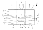
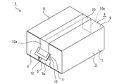
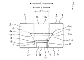
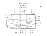
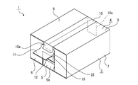
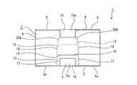
- FIG. 2 to FIG. 30 show an embodiment of the cardboard box of the present invention, and this figure is a perspective view of the cardboard box. It is a perspective view of the cardboard box shown in the state where the inner side wrap part and the outer side wrap part were opened. It is a front view of a cardboard box. It is a front view of the cardboard box which shows the example from which the length of the 2nd score line differs. It is a front view of the cardboard box which shows the example in which at least one of the 2nd score lines was inclined.
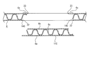
- FIG. 4 is an enlarged sectional view taken along line VI-VI in FIG. 3. It is a front view which shows the example in which the knob part and the pushing part were formed in the approximate center part of the 1st side part.
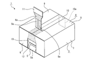
- FIG. 9 and 10 show the procedure for performing the peeling operation of the adhesive tape, and this figure is a perspective view showing a state in which the pushing portion is pushed. It is a perspective view which shows the state by which the knob part was pulled out. It is a perspective view which shows the state where the picked-up knob part pulled is pulled and the adhesive tape is peeled. It is a front view which shows the state by which the finger was inserted from opening and the knob part was hold
- the corrugated cardboard box in the embodiment shown below includes a bottom surface portion, a peripheral surface portion, and a top surface portion, and the peripheral surface portion has a pair of first side surface portions (toe surface portions) and a knob portion each having a knob portion and a pushing portion. And a pair of second side surface portions having no pushing portion.
- the direction in which the bottom surface portion and the top surface portion are aligned is the vertical direction
- the direction in which the pair of first side surface portions is aligned is the front-back direction
- the direction in which the pair of second side surface portions are aligned is the horizontal direction.
- the front, back, up, down, left and right directions shown below are for convenience of explanation, and the implementation of the present invention is not limited to these directions.
- corrugated cardboard box shown below has a structure in which each surface portion is sandwiched between a flat front liner and a back liner, each having a corrugated core.
- each cut line shown below is constant or a solid line cut line formed by a single cut It includes both broken line (perforated) cut lines formed by a plurality of cuts formed at indefinite intervals.
- each cut line has a configuration in which a cut is formed only in the front liner, a configuration in which a cut is formed only in the back liner, a configuration in which a cut is formed in the front liner and the core, the back liner and the middle It includes all configurations in which a cut is formed in the core, and a configuration in which a cut is formed in the front liner, the middle core, and the back liner and is penetrated from the front liner to the back liner.
- the cardboard box 1 is formed in, for example, a rectangular parallelepiped shape having different vertical and horizontal height dimensions, and the length in the front-rear direction is longer than the length (width) in the left-right direction.
- the cardboard box 1 may be formed in a cubic shape, and is a rectangular parallelepiped shape in which the length in the front-rear direction is the same as the length in the left-right direction, and the length in the front-rear direction is the same as the length in the up-down direction. It may be a rectangular parallelepiped shape in which the length in the left-right direction is the same as the length in the vertical direction.
- the cardboard box 1 includes a bottom surface portion 2, a peripheral surface portion 3, and a top surface portion 4 (see FIGS. 1 and 2).
- the bottom surface portion 2 is composed of four wrap portions 2a, 2a,..., And the four wrap portions 2a, 2a,. It is fixed to.
- the sticking tape 5 is stuck over each part of the peripheral surface part 3 from the joint part of the two wrap parts 2a and 2a.
- the peripheral surface portion 3 includes a pair of first side surface portions 6 and 6 and a pair of second side surface portions 7 and 7, and the lower edges of the pair of first side surface portions 6 and 6 are both front and rear sides of the bottom surface portion 2.
- the lower edges of the pair of second side surface portions 7 and 7 are continued to the left and right side edges of the bottom surface portion 2, respectively.
- the pair of first side surface portions 6 and 6 are positioned facing the front-rear direction and facing each other in the front-rear direction
- the pair of second side surface portions 7 and 7 are positioned facing the left-right direction and facing each other in the left-right direction.
- the first side surface portion 6 and the second side surface portion 7 have the same height, and the length of the first side surface portion 6 in the left-right direction is shorter than the length of the second side surface portion 7 in the front-rear direction. .
- the top surface portion 4 includes a pair of inner wrap portions 8 and 8 and a pair of outer wrap portions 9 and 9, and one end edges of the pair of inner wrap portions 8 and 8 are upper edges of the pair of first side surface portions 6 and 6, respectively.
- wrap parts 9 and 9 is continued by the upper edge of a pair of 2nd side surface parts 7 and 7, respectively.
- the top surface portion 4 has a pair of inner wrap portions 8, 8 and a pair of outer wrap portions 9, 9 folded into a substantially planar shape when the article is packed, and fixed to a substantially planar state by an adhesive tape 10.
- the pressure-sensitive adhesive tape 10 is affixed across a part of each of the pair of first side surface parts 6 and 6 from the joint part of the pair of outer wrap parts 9 and 9.
- the adhesive tape 10 and the adhesive tape 5 may be the same type or different types.
- the pair of first side surface parts 6 and 6 in the peripheral surface part 3 are respectively provided with knob parts 11 and 11 and pushing parts 12 and 12 continuously in the vertical direction (see FIGS. 1 to 3).
- the knobs 11 and 11 are portions that are pulled outward when unpacking, and the push-in portions 12 and 12 are portions that are pushed inward when unpacking.
- the knob part 11 and the pushing part 12 may be formed only on one first side face part 6.
- the knob portion 11 is formed as a region surrounded by four cut lines that are solid lines or broken lines. As shown in FIG. 3, the four cut lines include a first cut line 13 extending left and right, a pair of second cut lines 14 and 14 extending vertically, and a third cut line 15 extending left and right. It consists of.
- the first cut line 13 is formed as a boundary line with the pushing portion 12, and is formed in a solid line shape penetrating the first side surface portion 6, for example.
- the first cut line 13 may be formed in a broken line shape.
- the 1st score line 13 may be formed, for example so that there may be several short parts which do not have a score among the whole, and forms the 1st score line 13 in this way. Therefore, unintentional pushing (bending) of the knob portion 11 and the pushing portion 12 during transportation is difficult to occur, and the knob portion 11 and the pushing portion 12 can be bent with a small force to improve workability at the time of unpacking. Can do.
- the first cutting line 13 is formed in a solid line shape penetrating the first side surface portion 6, the force required to pull out the knob portion 11 at the time of unpacking is further reduced, and the knob portion 11 can be easily pulled out.
- the first cut line 13 is formed as a boundary line with the pushing portion 12, the first cut line 13 has a solid line shape penetrating the first side surface portion 6. By being formed, the force required to push the pushing portion 12 at the time of unpacking is further reduced, and the pushing portion 12 can be pushed easily.
- each of the second cut lines 14 and 14 is connected to both ends of the first cut line 13 and is formed in a parallel state with a separation in the left-right direction. Accordingly, the second cut lines 14 and 14 are positioned in parallel with the left and right side edges of the adhesive tape 10.
- the 2nd score line 14 is formed in the shape of a broken line which penetrates the 1st side part 6, for example.
- the width direction of the adhesive tape 10 at the tape side cut ends 14 a and 14 a is larger than the width H of the adhesive tape 10.
- the distance L is 2 mm to 10 mm larger than the width H.
- the adhesive tape 10 is attached to the knob portion 11 with the end portion 10a in the longitudinal direction being in an appropriate state. In this case, 1 mm is provided between the left and right side edges of the adhesive tape 10 and the second cut lines 14 and 14, respectively.
- An interval (margin) of 5 to 5 mm is formed. For example, as shown in FIGS.
- the length of the second cut lines 14, 14 is different, or at least one of the second cut lines 14, 14 is inclined, etc.
- the positions of the side cut ends 14a, 14a in the vertical direction may be different. In these cases, the distance L in the width direction of the adhesive tape 10 at the tape side cut ends 14a, 14a is more than the width H of the adhesive tape 10. It has been enlarged.
- Both ends of the third cut line 15 are connected to the upper ends of the second cut lines 14 and 14, respectively, the front liner 6a of the first side face 6 has no cut, and the first side face Only the back liner 6b of 6 or the back liner 6b of the first side surface portion 6 and the center core 6c are formed in a solid line shape or a broken line shape (see FIG. 6).
- the size of the cut is exaggerated for the sake of easy understanding (the same applies to the following drawings).
- the third cut line 15 is formed so as to have notches only in the back liner 6b or in the back liner 6b and the center core 6c, it functions as a fold when pulled out to the outside.
- the third cut line 15 may be formed in a solid line shape or a broken line shape penetrating the first side surface portion 6.
- the pushing portion 12 is formed as a region surrounded by four cut lines that are solid lines or broken lines. As shown in FIG. 3, the four cut lines include a fourth cut line 16 extending left and right, a pair of fifth cut lines 17 and 17 extending vertically, and a sixth cut line 18 extending left and right. It consists of.
- the 4th cut line 16 is formed as a boundary line with the knob part 11, is shared with the 1st cut line 13, and is formed in the shape of a solid line which penetrates the 1st side part 6, for example.
- the fourth cut line 16 may be formed in a broken line shape.
- the upper ends of the fifth cut lines 17 and 17 are respectively connected to both ends of the fourth cut line 16, and are formed in a parallel state separated in the left-right direction. Accordingly, the fifth cut lines 17 and 17 are positioned in parallel with the left and right side edges of the adhesive tape 5.
- the 5th cut line 17 is formed in the shape of a broken line which penetrates the 1st side part 6, for example.
- the sixth cut line 18 functions as a fold when the push portion 12 is pushed inward, and both ends are connected to the lower ends of the fifth cut lines 17 and 17, respectively.
- the first side face portion 6 The lower edge, that is, the bent portion that is the boundary between the first side surface portion 6 and the bottom surface portion 3 is matched. Therefore, since the sixth cut line 18 is creased in advance, the sixth cut line 18 may not be formed with a cut.
- a cut may be formed in the sixth cut line 18, and in this case, the sixth cut line 18 has a cut in the front liner 6a of the first side face portion 6.
- the sixth cut line 18 may be formed in a solid line shape or a broken line shape having a cut in only the front liner 6a or the front liner 6a and the center core 6c in order to make the pushing portion 12 easy to push.
- the sixth cut line 18 may be formed in a broken line shape penetrating the first side surface portion 6.
- the sixth cut line 18 forming the pushing portion 12 is aligned with the lower edge of the first side surface portion 6
- the sixth cut line 18 is the first side surface portion. It is also possible to configure to exist at a position other than the lower edge of 6.
- the knob portion 11 and the pushing portion 12 may be formed at a substantially central portion of the first side surface portion 6.
- the third cut line 15 forming the knob portion 11 coincides with the upper edge of the first side surface portion 6, that is, the bent portion that is the boundary portion between the first side surface portion 6 and the inner wrap portion 8. May be.
- the knob part 11 can be easily pulled out, and the third cut line 15 has a solid line or a broken line. It is also possible to omit the formation of the shape-like cut, and the manufacturing cost and the manufacturing time of the cardboard box 1 can be reduced.
- the end portions 5 a and 5 a on both sides in the longitudinal direction of the sticking tape 5 are the pressing portions 12 and 12, respectively. Is pasted.
- the left and right side edges of the end portion 5a are positioned inside the fifth cut lines 17 and 17, the upper edge of the end portion 5a is positioned below the fourth cut line 16, and the end portion 5a is It is affixed in a state where it does not straddle the pushing portion 12.
- the adhesive tape 10 has the end portions 10a and 10a on both sides in the longitudinal direction attached to the knob portions 11 and 11, respectively.
- the left and right side edges of the end portion 10a are positioned inside the second cut lines 14, 14, and the lower edge of the end portion 10a is positioned above the first cut line 13, and the left and right edges of the end portion 10a are Spaces are formed between both side edges and the second cut lines 14 and 14 and between the lower edge of the end portion 10a and the first cut line 13, and the end portion 10a does not straddle the knob portion 11. It is pasted in the state.
- the pushing portion 12 is pressed to push the pushing portion 12 inward (see FIG. 8).
- the pushing portion 12 is pushed inward, the fifth cut lines 17 and 17 are cut and the sixth cut line 18 is bent by the pressing force.
- the end portion 5 a of the sticking tape 5 is pushed inward together with the pushing portion 12. Since the end portion 5a of the sticking tape 5 is stuck without straddling the pressing portion 12, the adhesive force of the sticking tape 5 becomes a resistance to the force for pressing the pressing portion 12 when the pressing portion 12 is pushed.
- the pushing portion 12 can be pushed in smoothly with a small force.
- an opening 19 is formed in the portion of the first side face portion 6 where the pushing portion 12 was present.
- a finger is inserted into the opening 19 to grip the knob part 11, and the knob part 11 is pulled out (see FIG. 9).
- the knob part 11 is pulled out, the second cutting lines 14 and 14 are cut and the third cutting line 15 is bent by the pulling force, and the end part 10a of the adhesive tape 10 is also cut into the knob part. 11 is pulled out together.
- the distance L between the second cut lines 14 and 14 in the knob portion 11 is made larger than the width H of the adhesive tape 10, and the distance between the lower edge of the end portion 10 a and the first cut line 13 is also set.
- the end portion 10 a is formed so as not to straddle the knob portion 11. Therefore, the adhesive force of the adhesive tape 10 does not become resistance to the force for pulling out the knob portion 11 when the knob portion 11 is pulled out, and the knob portion 11 can be pulled out smoothly with a small force.
- the pulled knob portion 11 is pulled along the adhesive tape 10 (see FIG. 10).
- the third cutting line 15 in the front liner 6a is cut by the pulling force, and the upper part of the third cutting line 15 is peeled off together with the adhesive tape 10, and further the outer wrap.
- the surface liners 9 a and 9 a of the portions 9 and 9 where the adhesive tape 10 has been attached are peeled off together with the adhesive tape 10.
- the part shown with the pear place in FIG. 10 has shown the peeling trace after peeling.
- the entire front liner 6a and the front liners 9a and 9a in the thickness direction are peeled from the core, or only the surface portion is peeled off.
- the front liner 6 a of the first side face part 6 located on the opposite side to the drawn knob part 11 side is peeled off together with the opposite end part 10 a of the adhesive tape 10. Then, the entire adhesive tape 10 is peeled from the cardboard box 1.
- both the 1st side surface parts 6 and 6 have the knob parts 11 and 11 and the pushing part. 12 and 12, the pressure-sensitive adhesive tape 10 is formed by pulling both the push-in portions 11 and 11 outward and pulling them along the pressure-sensitive adhesive tape 10 after the both push-in portions 12 and 12 are pushed inward. It is also possible to peel off.
- the width of the knob portion 11 in the left-right direction is larger than the width of the adhesive tape 10, and the size of the knob portion 11 in the left-right direction is increased. Therefore, as shown in FIG. 11, when the finger 100 is inserted from the opening 19 and the knob portion 11 is to be pulled out, the nail 101 of the inserted finger 100 is not easily caught on the second cut lines 14 and 14. In addition, since the tip of the finger 100 is not easily directed to the outside of the knob part 11 in the left-right direction, it is possible to easily pull out the knob part 11 by gripping only the knob part 11 with the finger 100. .
- the pair of second cut lines 14 and 14 are orthogonal to the width direction of the adhesive tape 10, and are formed in a parallel state extending vertically.
- the distance between the second cut lines 14 and 14 is larger than the width H of the adhesive tape 10 at any position in the length direction (vertical direction) of the second cut lines 14 and 14, and the adhesive tape. Since the end 10a does not cover the second cut lines 14 and 14 regardless of the position of the tip edge of the end 10a in the vertical direction, the end 10a does not cover the second cut lines 14 and 14.
- the adhesive tape 10 can be easily and reliably peeled off.
- the end portion 10a of the adhesive tape 10 is attached to the knob portion 11
- the end portion 10a is used as the knob portion. 11 (see FIG. 12).
- the distance L in the width direction of the adhesive tape 10 of the tape-side cut ends 14 a and 14 a is made larger than the width H of the adhesive tape 10 in the second cut lines 14 and 14. Therefore, when pulling the knob part 11 and peeling off the front liner 6a of the first side face part 6, the left and right side edges of the front liner 6a gradually decrease in width as the peeler 10 is peeled off. There is a high probability of reaching the left and right side edges of the end 10a without reaching the lower edge (see FIG. 13).
- the tip portion of the end portion 10a has already been peeled off together with the front liner 6a, and the adhesive tape 10 can be peeled by further pulling the knob portion 11 along the adhesive tape 10 (see FIG. 14).
- the part shown with the pear place in FIG.13 and FIG.14 has shown the peeling trace after peeling.
- the distance L in the width direction of the adhesive tape 10 between the tape-side cut ends 14 a and 14 a is larger than the width H of the adhesive tape 10.
- the adhesive force of the adhesive tape 10 is unlikely to be a resistance to the force for peeling the adhesive tape 10, and the sticking position of the adhesive tape 10 is limited.
- the adhesive tape 10 can be easily peeled off.
- knob portion 11A according to a first modification will be described (see FIGS. 15 and 16).
- the knob part 11A is inclined so as to be separated from each other as the second cut lines 14A and 14A go upward, and is formed in an isosceles trapezoidal shape.
- the knob portion 11A has a distance L1 between the upper ends in the width direction of the adhesive tape 10 of the tape-side cut ends 14a, 14a larger than the width H of the adhesive tape 10, A distance L ⁇ b> 2 in the width direction of the adhesive tape 10 between the lower ends of the second score lines 14 ⁇ / b> A and 14 ⁇ / b> A is made smaller than the width H of the adhesive tape 10.
- the lower ends of the second score lines 14A and 14A may be respectively connected to both ends of the first score line 13 (see FIG. 15). It may be continuous (refer to Drawing 16), and knob part 11A should just be formed according to the size of the width of adhesive tape 10 in the size in the left-right direction.
- the knob part 11A is formed, even if the end part 10a of the adhesive tape 10 is affixed to the upper side of the knob part 11, the second cut lines 14A and 14A are cut off on the tape side. Since the distance L1 in the width direction of the adhesive tape 10 between the insertion ends 14a and 14a is made larger than the width H of the adhesive tape 10, the knob 11A is pulled to peel off the front liner 6a of the first side surface 6. There is a high probability that the left and right side edges of the front liner 6a will reach the left and right side edges of the end portion 10a.
- the adhesive force of the adhesive tape 10 is unlikely to be a resistance to the force for peeling the adhesive tape 10, and the sticking position of the adhesive tape 10 is limited.
- the adhesive tape 10 can be easily peeled off.
- the isosceles trapezoidal knob portion 11A is shown as an example as a first modification.
- the corrugated cardboard box 1 at least between the upper ends of the second cut lines 14A, 14A, that is, The distance L1 in the width direction of the pressure-sensitive adhesive tape 10 at the tape-side cut ends 14a and 14a only needs to be larger than the width H of the pressure-sensitive adhesive tape 10, and various shapes can be used as long as the knob part satisfies such a configuration. It is possible to form.
- the knob part 11B is formed in a broken line shape in which the third cut line 15B penetrates the first side face part 6, and the cuts 20, 20,... Of the front liner 6a are formed in the third cut line 15B.
- the length of each is shorter than the length of the notches 21, 21,... Of the back liner 6b (see FIG. 17).
- FIG. 17 is an enlarged horizontal sectional view including the third cut line 15B.
- trapezoidal cutting teeth 51, 51,... are arranged at equal intervals, and the cutting teeth 51, 51,. By inserting, notches 20, 20,... And notches 21, 21,.
- the 3rd cut line 15B can be formed easily and rapidly by using the cut formation apparatus 50, improvement of mass-productivity by making manufacture of the corrugated cardboard box 1 and shortening of manufacture time improved. You can plan.
- the length of the notches 20, 20,... Of the front liner 6a is shorter than the lengths of the notches 21, 21,. It is hard to be displaced in the direction in which the knob portion 11B is pushed inward, and is easily displaced in the direction of being pulled out. Further, the length of the notches 20, 20,... Of the front liner 6a is made shorter than the lengths of the notches 21, 21,. It is difficult to separate in the direction, and it is easy to separate in the direction pulled out, and the adhesive tape 10 can be easily peeled off while ensuring the high strength of the cardboard box 1.
- the knob part 11B is difficult to be pushed in and easily pulled out, the knob part 11B is not pushed in unintentionally during transportation, and the knob part 11B can be easily pulled out.
- the adhesive tape 10 is pasted without straddling the knob part, so that the adhesive force of the adhesive tape 10 does not become a resistance in the pushing direction of the knob part, and the knob There is a possibility that a problem that the part is easily pushed in may occur, but by forming the knob part 11B having a configuration in which the push-in is difficult to occur, it is possible to prevent such a problem from occurring.
- the configuration in which the cut length of the front liner 6a is shorter than the cut length of the back liner 6b can be applied to the second cut line in addition to the third cut line 15B. Is possible.
- the knob portion becomes more difficult to be pushed in, and the intention during transportation, etc. The push-in portion that is not pressed becomes even less likely to occur.
- the cut length of the front liner 6a is shorter than the cut length of the back liner 6b to the second cut line, in the direction in which the knob portion 11B is pushed inward. It becomes difficult to separate further, and it becomes easier to separate in the direction to be pulled out, and it becomes possible to more easily perform the peeling operation of the adhesive tape 10 while securing a higher strength of the cardboard box 1.
- FIG. 19 is a diagram showing a state before the knob part 11C is pulled out
- FIG. 20 is a diagram conceptually showing a state in which the knob part 11C is pulled out.
- the knob part 11C is formed in a broken line shape in which the second cut lines 14C, 14C penetrate the first side face part 6, and the positions of the cuts 22, 22, ... formed in the front liner 6a. Are made outside in the left-right direction from the positions of the notches 23, 23,... Formed in the back liner 6b. Accordingly, in the knob portion 11C, the distance between the second cut lines 14C and 14C in the front liner 6a is made larger than the distance between the second cut lines 14C and 14C in the back liner 6b.
- the notches 22, 22,... And the notches 23, 23,... are formed with their cut surfaces inclined with respect to the left-right direction.
- the dashed-dotted line shown in FIG. 19 is an imaginary line for showing the cutting direction of notches 22, 22, ..., 23,23, ....
- the notches 22, 22,... And the notches 23, 23,... are inclined so as to be displaced in the left-right direction as they go in the front-rear direction.
- the second cut lines 14C and 14C may be formed in a solid line shape.
- knob part 11C is difficult to be pushed in and easily pulled out, the knob part 11C is not pushed in unintentionally during transportation, and the knob part 11C can be easily pulled out.
- the second cut lines 14C and 14C are formed in a broken line shape
- the second cut lines 14C and 14C are formed using the comb-shaped cut forming apparatus 50 shown in the second modification. It is possible to form.
- the second cut lines 14C and 14C using the cut forming device 50, it is possible to improve the mass productivity by facilitating the manufacture of the cardboard box 1 and shortening the manufacturing time.
- the lengths of the cuts 22, 22,... Formed on the front liner 6a are the back liner 6b. It becomes shorter than the length of the cuts 23, 23,. Therefore, since the knob part 11C is more difficult to push in and easier to pull out, unintentional pushing of the knob part 11C during transportation or the like is less likely to occur, and the knob part 11C can be pulled out more easily.
- FIG. 21 is a diagram showing a state before the knob portion 11D is pulled out
- FIG. 22 is a diagram conceptually showing a state in which the knob portion 11D is pulled out.
- the second cut lines 14D, 14D are formed in a broken line shape, and cuts 24, 24,... Are formed across the front liner 6a or the front liner 6a and the core 6c, Cuts 25, 25,... Are formed across the back liner 6b or the back liner 6b and the center core 6c.
- the position of the notches 24, 24, ... formed on the front liner 6a side is outside in the left-right direction from the positions of the cuts 25, 25, ... formed on the back liner 6b side. Has been. Accordingly, in the knob portion 11D, the distance between the second cut lines 14D and 14D in the front liner 6a is made larger than the distance between the second cut lines 14D and 14D in the back liner 6b.
- the cuts 24, 24,... And the cuts 25, 25,... are formed with their cut surfaces facing in the left-right direction.
- 21 is an imaginary line for indicating the cutting direction of the cuts 24, 24,..., 25, 25,.
- the second cut lines 14D and 14D may be formed in a solid line shape.
- the knob portion 11D has a knob.
- the portions 6y and 6y of the difference between the distance on the front liner 6a side and the distance on the back liner 6b side in the left-right direction of the child portion 11D are subjected to the resistance (resistance) applied to the knob portion 11D from the outer surface side. )
- knob part 11D is difficult to be pushed in and easily pulled out, the knob part 11D is not pushed in unintentionally during transportation or the like, and the knob part 11D can be easily pulled out.
- the knob part 11E and the pushing part 12E are each formed in a rectangular shape, the width in the left-right direction of the pushing part 12E is made smaller than the width in the left-right direction of the knob part 11E, and the area of the pushing part 12E is the area of the knob part 11E. It is made smaller (see FIG. 23).
- the pushing part 12E is made smaller than the area of the knob part 11E, the pushing part 12E is less likely to be pushed than the knob part 11E, so that the unintended pushing part 12E is not easily pushed in during transportation. A good conveyance state can be ensured.
- the pushing portion is easily structured so as to be pushed easily with a small force, it is preferable to make the pushing portion 12E difficult to push by making the area of the pushing portion 12E smaller than the area of the knob portion 11E. This is an effective means for securing the conveyance state.
- the shape of the knob portion 11E and the push-in portion 12E is not limited to a rectangular shape.
- the knob portion 11E is formed in an isosceles trapezoid shape.
- the area of the pushing portion 12E can be made smaller than the area of the knob portion 11E.
- knob portion 11F and the pushing portion 12F according to the sixth modification will be described (see FIG. 25).
- the knob part 11F and the pushing part 12F have second cut lines 14F and 14F and fifth cut lines 17F and 17F formed in broken lines.
- the lengths of the cuts 26, 26, ... of the second cut lines 14F, 14F are shorter than the lengths of the cuts 27, 27, ... of the fifth cut lines 17F, 17F.
- at least one of the notch 26 and the notch 27 is formed as a notch penetrating from the front liner 6a to the back liner 6c, and the length of the notch in the front liner 6a and the notch in the back liner 6c are different.
- the longest cut length of the cuts 26 is shorter than the longest cut length of the cuts 27.
- the pusher part 11F is difficult to be pushed in and the pusher part 12F is made easy to push in. Therefore, the pusher part 11F is not pushed in unintentionally during transportation and the like, and a good conveyance state can be secured and the adhesive tape 10 can be opened.
- the pushing portion 12F can be easily pushed during the bundling operation, and the workability in the unpacking operation can be improved.
- knob part 11 or the pushing part 12 since the other examples shown below are different from the above-described knob part 11 or the pushing part 12 in that some of the configurations are different or only a part of the configuration is added, the knob part 11 Or only a different part compared with the pushing part 12 is demonstrated in detail, About the other part, the code
- auxiliary cut lines 28 and 28 are formed above the second cut lines 14 and 14 in the first side surface portion 6, respectively (see FIG. 26).
- the auxiliary cut lines 28, 28 are formed in a solid line extending in the vertical direction, and the lower ends thereof are aligned with or located in the vicinity of the upper ends of the second cut lines 14, 14, respectively.
- the upper ends of the auxiliary cut lines 28 and 28 are positioned outside the left and right side edges of the adhesive tape 10 in the left and right direction.
- the auxiliary score lines 28 and 28 are formed in the whole thickness direction of the front liner 6a or only on the surface portion of the front liner 6a.
- auxiliary cut lines 28 and 28 When the auxiliary cut lines 28 and 28 are formed, it is particularly effective when the end portion 10a of the adhesive tape 10 is attached to the upper side of the knob portion 11, and the tab liner 11 is pulled to pull the front liner.
- the left and right broken portions in the front liner 6a are guided to the auxiliary cut lines 28, 28, and the portion between the auxiliary cut lines 28, 28 in the front liner 6a is peeled off (FIG. 27).
- the tip of the end portion 10a of the adhesive tape 10 is peeled off together with the front liner 6a, and the knob portion 11 is further pulled.
- the left and right side edges of the front liner 6a that gradually decrease in width as they are peeled off do not reach the lower edge of the end portion 10a but reach the left and right side edges of the end portion 10a.
- the adhesive tape 10 can be peeled off together with the front liner 6a by further pulling the knob part 11 along the adhesive tape 10.
- the adhesive force of the adhesive tape 10 peels off the adhesive tape 10 even when the end portion 10a is not attached to the knob portion 11.
- the adhesive tape 10 can be easily peeled off regardless of the position where the adhesive tape 10 is applied.
- auxiliary score lines 28, 28 are not formed in the entire thickness direction of the front liner 6a or only on the surface portion of the front liner 6a and do not penetrate the first side surface portion 6, the auxiliary score lines 28, By forming 28, the strength of the first side face portion 6 is not greatly reduced, and by forming the auxiliary cut lines 28, 28, the adhesive tape 10 is secured after securing sufficient strength of the cardboard box 1. It can be easily peeled off.
- auxiliary cutting lines 28A and 28A that are inclined instead of the auxiliary cutting lines 28 and 28 (see FIG. 28).
- the auxiliary cut lines 28A and 28A are inclined so as to approach each other as they go upward, and the lower ends thereof are aligned with or located in the vicinity of the upper ends of the second cut lines 14 and 14, respectively.
- the auxiliary cut lines 28A, 28A have upper ends that are respectively coincident with the left and right side edges of the adhesive tape 10, or are located inside the left and right side edges in the left and right direction.
- the auxiliary score lines 28A and 28A are formed in the whole thickness direction of the front liner 6a or only on the surface portion of the front liner 6a.
- auxiliary cut lines 28A and 28A are formed, it is particularly effective in a state where the end portion 10a of the adhesive tape 10 is attached to the upper side of the knob portion 11, and the table liner is pulled by pulling the knob portion 11.
- the left and right broken portions in the front liner 6a are guided to the auxiliary cut lines 28A and 28A, and the portion between the auxiliary cut lines 28A and 28A in the front liner 6a is peeled off.
- the left and right broken portions of the front liner 6a are guided to the auxiliary cut lines 28A and 28A, so that both left and right edges of the front liner 6a are the end portions 10a.
- the tip portion of the end portion 10a of the adhesive tape 10 is peeled off together with the front liner 6a, and the adhesive tape 10 can be peeled off together with the front liner 6a by further pulling the knob portion 11.
- the adhesive force of the adhesive tape 10 peels off the adhesive tape 10 even when the end portion 10a is not attached to the knob portion 11.
- the adhesive tape 10 can be easily peeled off regardless of the position where the adhesive tape 10 is applied.
- the sticking position of the adhesive tape 10 is concerned.
- the adhesive tape 10 can be reliably peeled.
- auxiliary score lines 28A, 28A are not the slits formed in the entire thickness direction of the table liner 6a or only on the surface portion of the table liner 6a and penetrating the first side surface portion 6, the auxiliary score lines 28A, By forming 28A, the strength of the first side surface portion 6 is not greatly reduced. By forming the auxiliary cut lines 28A, 28A, the adhesive tape 10 is secured after securing sufficient strength of the cardboard box 1. It can be easily peeled off.
- pick parts 11 and 11 and the pushing parts 12 and 12 for peeling the adhesive tape 10 and the sticking tape 5 respectively are formed in the 1st side part 6 (FIG. 29). reference).
- the knob part 11 and the pushing part 12 are formed on the upper side of the first side face part 6, and the knob part 11 and the pushing part 12 are also formed on the lower side.
- the knob part 11 and the pressing part 12 positioned on the upper side are for peeling the adhesive tape 10
- the knob part 11 and the pressing part 12 positioned on the lower side are for peeling the adhesive tape 5.
- the pusher portion 11 and the pusher portion 12 located on the lower side are formed such that the pusher portion 12 and the pusher portion 11 are successively arranged in the vertical direction.
- the adhesive tape 10 is peeled off using the pusher portion 11 and the pusher portion 12 positioned on the upper side, and the adhesive tape 5 is attached using the pusher portion 12 and the pusher portion 11 located on the lower side.
- peeling off both the adhesive tape 10 and the adhesive tape 5 can be easily peeled off, which is convenient, for example, when the cardboard box 1 is folded or discarded.
- a combined portion 29 composed of one knob portion 11 and one pushing portion 12 is formed on the first side surface portion 6. It is also possible (see FIG. 30).
- the combined portion 29 is composed of a first portion 29a and a second portion 29b formed continuously in the vertical direction, and one of the first portion 29a and the second portion 29b functions as the knob portion 11 and the other is pushed in. It functions as the unit 12.
- the first portion 29a positioned on the upper side functions as the knob portion 11
- the second portion 29b positioned on the lower side functions as the pushing portion 12.
- the sticking tape 5 is peeled off, the first portion 29 a positioned on the upper side functions as the push-in portion 12, and the second portion 29 b positioned on the lower side functions as the knob portion 11.
- the adhesive tape 10 is peeled off, first, the second portion 29b that functions as the push-in portion 12 is pushed in, then the first portion 29a that functions as the knob portion 11 is pulled out, and the pulled-out 29a is adhesively bonded.
- the adhesive tape 10 is peeled off together with the front liner 6a.
- the adhesive tape 5 is peeled off, first, the first portion 29a that functions as the push-in portion 12 is pushed, and then the second portion 29b that functions as the knob portion 11 is pulled out, and the pulled-out 29a is pulled out.
- the sticking tape 5 is peeled off together with the front liner 6a.
- the adhesive tape 10 and the adhesive tape 5 are peeled off using the first portion 29a positioned on the upper side and the second portion 29b positioned on the lower side. By doing so, it is possible to easily perform the peeling operation of the adhesive tape 10 and the sticking tape 5, which is convenient, for example, when the cardboard box 1 is folded or discarded.
- the dual-purpose portion 29 there is one portion that functions as the knob portion 11 or the push-in portion 12, so that the high strength of the first side surface portion 6 is ensured accordingly, and the corrugated cardboard High strength as a whole of the box 1 can be ensured.
- the first through sixth cut lines are all formed in a straight line.
- the first through sixth cut lines are limited to a straight line.
- the first to sixth cut lines can be formed in a curved shape as necessary, or can be formed in a combination of a straight line and a curved line. is there.
- first through sixth cut lines may be inclined with respect to the left-right direction or the up-down direction as necessary.
- first through sixth cut lines are one in which the continuous cut lines of these are a combination of a straight line and a curved line or a combination of a curved line and a curved line without an angular portion. It may be formed as a line.
- a linear first score line and a curved second score line are formed as one line, and one score line is defined as a first score line based on a predetermined intermediate point.
- the other cut line may be formed as the second cut line.
Abstract
Priority Applications (4)
| Application Number | Priority Date | Filing Date | Title |
|---|---|---|---|
| JP2015526433A JP5894340B1 (ja) | 2014-06-13 | 2014-06-13 | 段ボール箱 |
| US15/318,242 US10906693B2 (en) | 2014-06-13 | 2014-06-13 | Corrugated fiberboard box |
| PCT/JP2014/065737 WO2015189984A1 (fr) | 2014-06-13 | 2014-06-13 | Boîte en panneaux de fibre ondulée |
| TW104118312A TWI554448B (zh) | 2014-06-13 | 2015-06-05 | Corrugated boxes |
Applications Claiming Priority (1)
| Application Number | Priority Date | Filing Date | Title |
|---|---|---|---|
| PCT/JP2014/065737 WO2015189984A1 (fr) | 2014-06-13 | 2014-06-13 | Boîte en panneaux de fibre ondulée |
Publications (1)
| Publication Number | Publication Date |
|---|---|
| WO2015189984A1 true WO2015189984A1 (fr) | 2015-12-17 |
Family
ID=54833112
Family Applications (1)
| Application Number | Title | Priority Date | Filing Date |
|---|---|---|---|
| PCT/JP2014/065737 WO2015189984A1 (fr) | 2014-06-13 | 2014-06-13 | Boîte en panneaux de fibre ondulée |
Country Status (4)
| Country | Link |
|---|---|
| US (1) | US10906693B2 (fr) |
| JP (1) | JP5894340B1 (fr) |
| TW (1) | TWI554448B (fr) |
| WO (1) | WO2015189984A1 (fr) |
Families Citing this family (18)
| Publication number | Priority date | Publication date | Assignee | Title |
|---|---|---|---|---|
| JP6589742B2 (ja) * | 2016-05-31 | 2019-10-16 | 京セラドキュメントソリューションズ株式会社 | 梱包材 |
| US10583977B2 (en) | 2016-08-16 | 2020-03-10 | Mp Global Products, L.L.C. | Method of making an insulation material and an insulated mailer |
| US10442600B2 (en) | 2017-04-07 | 2019-10-15 | Pratt Retail Specialties, Llc | Insulated bag |
| US10800595B2 (en) | 2017-04-07 | 2020-10-13 | Pratt Retail Specialties, Llc | Box liner |
| US10604304B2 (en) | 2017-05-09 | 2020-03-31 | Pratt Retail Specialties, Llc | Insulated bag with handles |
| US10954057B2 (en) | 2017-05-09 | 2021-03-23 | Pratt Retail Specialties, Llc | Insulated box |
| US10551110B2 (en) | 2017-07-31 | 2020-02-04 | Pratt Retail Specialties, Llc | Modular box assembly |
| US10507968B2 (en) | 2017-12-18 | 2019-12-17 | Pratt Retail Specialties, Llc | Modular box assembly |
| US10947025B2 (en) | 2017-12-18 | 2021-03-16 | Pratt Corrugated Holdings, Inc. | Insulated block packaging assembly |
| US11059652B2 (en) | 2018-05-24 | 2021-07-13 | Pratt Corrugated Holdings, Inc. | Liner |
| US11066228B2 (en) | 2018-11-13 | 2021-07-20 | Pratt Retail Specialties, Llc | Insulated box assembly and temperature-regulating lid therefor |
| US10875678B2 (en) | 2018-11-13 | 2020-12-29 | Pratt Retail Specialties, Llc | Box insert with vertical rails |
| US10882684B2 (en) | 2019-05-02 | 2021-01-05 | Pratt Retail Specialties, Llc | Box defining walls with insulation cavities |
| US11230404B2 (en) | 2019-11-26 | 2022-01-25 | Pratt Corrugated Holdings, Inc. | Perforated collapsible box |
| US11358749B2 (en) * | 2020-01-10 | 2022-06-14 | Fresenius Medical Care Holdings, Inc. | Packaging containers and related methods |
| US11718464B2 (en) | 2020-05-05 | 2023-08-08 | Pratt Retail Specialties, Llc | Hinged wrap insulated container |
| USD968950S1 (en) * | 2020-08-10 | 2022-11-08 | Pratt Corrugated Holdings, Inc. | Perforated collapsible box |
| US11312531B1 (en) * | 2021-10-14 | 2022-04-26 | Rachman Ezell | Dual-action carton separation system and method of use |
Citations (5)
| Publication number | Priority date | Publication date | Assignee | Title |
|---|---|---|---|---|
| JPH0263323U (fr) * | 1988-10-27 | 1990-05-11 | ||
| JPH11501601A (ja) * | 1995-12-19 | 1999-02-09 | ザ、プロクター、エンド、ギャンブル、カンパニー | 商用物品を包装するためのコルゲートボックス |
| JP2001139024A (ja) * | 1999-11-15 | 2001-05-22 | Tomoku Co Ltd | 梱包箱 |
| JP2009091003A (ja) * | 2007-10-05 | 2009-04-30 | Akira Maruo | 粘着テープ易開封性段ボール箱 |
| JP3164053U (ja) * | 2010-08-31 | 2010-11-11 | 大王製紙パッケージ株式会社 | 段ボール箱 |
Family Cites Families (14)
| Publication number | Priority date | Publication date | Assignee | Title |
|---|---|---|---|---|
| US2233602A (en) * | 1938-02-11 | 1941-03-04 | Quaker Oats Co | Cardboard or like box or container |
| US2706076A (en) * | 1953-10-12 | 1955-04-12 | Waldorf Paper Products Co | Container opener |
| US3019944A (en) * | 1957-12-30 | 1962-02-06 | Kimberly Clark Co | Dispensing carton for flexible sheets |
| US3302857A (en) * | 1965-07-08 | 1967-02-07 | Waldorf Paper Prod Co | Easy opening container |
| JP2646410B2 (ja) | 1991-12-10 | 1997-08-27 | 株式会社テック | 包装用箱体 |
| US5582571A (en) * | 1992-04-03 | 1996-12-10 | Container Graphics Corporation | Apparatus and method for perforating and creasing paperboard |
| GB9210671D0 (en) * | 1992-05-19 | 1992-07-01 | Sca Packaging Ltd | Container |
| GB9525970D0 (en) * | 1995-12-19 | 1996-02-21 | Domino Printing Sciences Plc | Continuous ink jet printer |
| JP3057683U (ja) | 1998-09-11 | 1999-06-02 | 王子製紙株式会社 | 簡易開封箱 |
| GB9929865D0 (en) * | 1999-12-18 | 2000-02-09 | Smith David S Packaging | Carton opening arrangement |
| CN2576646Y (zh) * | 2002-09-05 | 2003-10-01 | 简博为 | 预贴在纸箱表面的拆带片 |
| TW585828B (en) * | 2002-10-25 | 2004-05-01 | Bo-Wei Jian | Device for unpacking carton easily |
| JP4874585B2 (ja) | 2005-06-30 | 2012-02-15 | ザ・パック株式会社 | 外装用段ボール箱 |
| US20070063008A1 (en) * | 2005-09-22 | 2007-03-22 | Ali El-Afandi | Perforated packaging |
-
2014
- 2014-06-13 WO PCT/JP2014/065737 patent/WO2015189984A1/fr active Application Filing
- 2014-06-13 US US15/318,242 patent/US10906693B2/en active Active
- 2014-06-13 JP JP2015526433A patent/JP5894340B1/ja active Active
-
2015
- 2015-06-05 TW TW104118312A patent/TWI554448B/zh active
Patent Citations (5)
| Publication number | Priority date | Publication date | Assignee | Title |
|---|---|---|---|---|
| JPH0263323U (fr) * | 1988-10-27 | 1990-05-11 | ||
| JPH11501601A (ja) * | 1995-12-19 | 1999-02-09 | ザ、プロクター、エンド、ギャンブル、カンパニー | 商用物品を包装するためのコルゲートボックス |
| JP2001139024A (ja) * | 1999-11-15 | 2001-05-22 | Tomoku Co Ltd | 梱包箱 |
| JP2009091003A (ja) * | 2007-10-05 | 2009-04-30 | Akira Maruo | 粘着テープ易開封性段ボール箱 |
| JP3164053U (ja) * | 2010-08-31 | 2010-11-11 | 大王製紙パッケージ株式会社 | 段ボール箱 |
Also Published As
| Publication number | Publication date |
|---|---|
| JPWO2015189984A1 (ja) | 2017-04-20 |
| US20170121052A1 (en) | 2017-05-04 |
| JP5894340B1 (ja) | 2016-03-30 |
| US10906693B2 (en) | 2021-02-02 |
| TWI554448B (zh) | 2016-10-21 |
| TW201607855A (zh) | 2016-03-01 |
Similar Documents
| Publication | Publication Date | Title |
|---|---|---|
| JP5894340B1 (ja) | 段ボール箱 | |
| JP5458089B2 (ja) | 包装用の箱及びそれを作り出すためのブランクのセット | |
| JP5960547B2 (ja) | 紙製容器および紙製品の破断用罫線構造 | |
| JP6110234B2 (ja) | 包装体およびその開封用罫線構造 | |
| JP3200716U (ja) | 天面開封箱 | |
| JP5928889B2 (ja) | 包装用箱 | |
| JP3147982U (ja) | ラップアラウンドケースの開梱部構造 | |
| JP2017095136A (ja) | 包装箱 | |
| JP3154972U (ja) | 段ボール箱 | |
| JP6259015B2 (ja) | 包装容器 | |
| JP6799911B2 (ja) | 包装箱 | |
| JP6523648B2 (ja) | 包装箱 | |
| JP6524141B2 (ja) | 包装箱 | |
| JP6849463B2 (ja) | 箱用シート | |
| JP3164053U (ja) | 段ボール箱 | |
| US10435196B2 (en) | Receiving container | |
| JP2019001475A (ja) | 包装袋 | |
| JP5055923B2 (ja) | 帯状の開封構造と該開封構造が設けられた紙箱又はダンボール箱 | |
| JP6676444B2 (ja) | 包装箱 | |
| JP6472506B2 (ja) | 手袋包装体 | |
| JP5235167B2 (ja) | 紙製品の罫線構造および該罫線構造を用いた紙製品 | |
| JP2007069929A (ja) | 段ボール板製包装箱 | |
| JP5218912B2 (ja) | 内容器ブランク | |
| JP2006151440A (ja) | 包装箱 | |
| JP2007153391A (ja) | 紙製品の破断端部構造および該破断端部構造を用いた包装箱 |
Legal Events
| Date | Code | Title | Description |
|---|---|---|---|
| ENP | Entry into the national phase |
Ref document number: 2015526433 Country of ref document: JP Kind code of ref document: A |
|
| 121 | Ep: the epo has been informed by wipo that ep was designated in this application |
Ref document number: 14894481 Country of ref document: EP Kind code of ref document: A1 |
|
| WWE | Wipo information: entry into national phase |
Ref document number: 15318242 Country of ref document: US |
|
| NENP | Non-entry into the national phase |
Ref country code: DE |
|
| 122 | Ep: pct application non-entry in european phase |
Ref document number: 14894481 Country of ref document: EP Kind code of ref document: A1 |