以下に、本発明段ボール箱を実施するための形態について添付図面を参照して説明する。
Hereinafter, embodiments for carrying out the cardboard box of the present invention will be described with reference to the accompanying drawings.
尚、以下に示す実施の形態における段ボール箱は底面部と周面部と天面部から成り、周面部は摘子部及び押込部をそれぞれ有する一対の第1の側面部(つま面部)と摘子部及び押込部を有さない一対の第2の側面部とから成る。以下の説明にあっては、底面部と天面部が並ぶ方向を上下方向とし、一対の第1の側面部が並ぶ方向を前後方向とし、一対の第2の側面部が並ぶ方向を左右方向とする。但し、以下に示す前後上下左右の方向は説明の便宜上のものであり、本発明の実施に関しては、これらの方向に限定されることはない。
The corrugated cardboard box in the embodiment shown below includes a bottom surface portion, a peripheral surface portion, and a top surface portion, and the peripheral surface portion has a pair of first side surface portions (toe surface portions) and a knob portion each having a knob portion and a pushing portion. And a pair of second side surface portions having no pushing portion. In the following description, the direction in which the bottom surface portion and the top surface portion are aligned is the vertical direction, the direction in which the pair of first side surface portions is aligned is the front-back direction, and the direction in which the pair of second side surface portions are aligned is the horizontal direction. To do. However, the front, back, up, down, left and right directions shown below are for convenience of explanation, and the implementation of the present invention is not limited to these directions.
また、以下に示す段ボール箱は各面部が、何れも波型状に形成された中芯がそれぞれ平板状の表ライナーと裏ライナーに挟持された構成にされている。
Also, the corrugated cardboard box shown below has a structure in which each surface portion is sandwiched between a flat front liner and a back liner, each having a corrugated core.
さらに、以下に示す段ボール箱における所定の各面部には切込線が形成されているが、以下に示す各切込線は単一の切込によって構成された実線状の切込線と一定又は不定の間隔で形成された複数の切込によって構成された破線状(ミシン目状)の切込線の双方を含むものである。
Furthermore, although the cut line is formed in each predetermined surface part in the cardboard box shown below, each cut line shown below is constant or a solid line cut line formed by a single cut It includes both broken line (perforated) cut lines formed by a plurality of cuts formed at indefinite intervals.
さらにまた、各切込線は表ライナーのみに切込が形成された構成、裏ライナーのみに切込が形成された構成、表ライナーと中芯に切込が形成された構成、裏ライナーと中芯に切込が形成された構成、表ライナーと中芯と裏ライナーに切込が形成されて表ライナーから裏ライナーに亘って貫通された構成の全ての構成を含むものである。
Furthermore, each cut line has a configuration in which a cut is formed only in the front liner, a configuration in which a cut is formed only in the back liner, a configuration in which a cut is formed in the front liner and the core, the back liner and the middle It includes all configurations in which a cut is formed in the core, and a configuration in which a cut is formed in the front liner, the middle core, and the back liner and is penetrated from the front liner to the back liner.
<段ボール箱の構造>
先ず、段ボール箱1の基本的な構造について説明する(図1乃至図7参照)。
<Structure of cardboard box>
First, the basic structure of the cardboard box 1 will be described (see FIGS. 1 to 7).
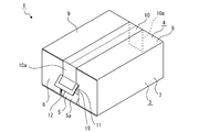
段ボール箱1は、例えば、縦横高さの寸法が異なる直方体形状に形成され、前後方向における長さが左右方向における長さ(幅)より長くされている。尚、段ボール箱1は、立方体形状に形成されていてもよく、また、前後方向における長さと左右方向における長さが同じにされた直方体形状、前後方向における長さと上下方向における長さが同じにされた直方体形状、左右方向における長さと上下方向における長さが同じにされた直方体形状であってもよい。
The cardboard box 1 is formed in, for example, a rectangular parallelepiped shape having different vertical and horizontal height dimensions, and the length in the front-rear direction is longer than the length (width) in the left-right direction. The cardboard box 1 may be formed in a cubic shape, and is a rectangular parallelepiped shape in which the length in the front-rear direction is the same as the length in the left-right direction, and the length in the front-rear direction is the same as the length in the up-down direction. It may be a rectangular parallelepiped shape in which the length in the left-right direction is the same as the length in the vertical direction.
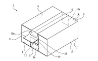
段ボール箱1は底面部2と周面部3と天面部4から成る(図1及び図2参照)。
The cardboard box 1 includes a bottom surface portion 2, a peripheral surface portion 3, and a top surface portion 4 (see FIGS. 1 and 2).
底面部2は四つのラップ部2a、2a、・・・から成り、四つのラップ部2a、2a、・・・が物品の梱包時に略平面状に折り畳まれ貼着テープ5によって略平面状の状態に固定されている。貼着テープ5は二つのラップ部2a、2aの合わせ目部分から周面部3の各一部に亘って貼り付けられている。
The bottom surface portion 2 is composed of four wrap portions 2a, 2a,..., And the four wrap portions 2a, 2a,. It is fixed to. The sticking tape 5 is stuck over each part of the peripheral surface part 3 from the joint part of the two wrap parts 2a and 2a.
周面部3は一対の第1の側面部6、6と一対の第2の側面部7、7とから成り、一対の第1の側面部6、6の下縁がそれぞれ底面部2の前後両側縁に連続され、一対の第2の側面部7、7の下縁がそれぞれ底面部2の左右両側縁に連続されている。一対の第1の側面部6、6は前後方向を向き前後方向において対向して位置され、一対の第2の側面部7、7は左右方向を向き左右方向において対向して位置されている。第1の側面部6と第2の側面部7は高さが同じにされ、第1の側面部6の左右方向における長さは第2の側面部7の前後方向における長さより短くされている。
The peripheral surface portion 3 includes a pair of first side surface portions 6 and 6 and a pair of second side surface portions 7 and 7, and the lower edges of the pair of first side surface portions 6 and 6 are both front and rear sides of the bottom surface portion 2. The lower edges of the pair of second side surface portions 7 and 7 are continued to the left and right side edges of the bottom surface portion 2, respectively. The pair of first side surface portions 6 and 6 are positioned facing the front-rear direction and facing each other in the front-rear direction, and the pair of second side surface portions 7 and 7 are positioned facing the left-right direction and facing each other in the left-right direction. The first side surface portion 6 and the second side surface portion 7 have the same height, and the length of the first side surface portion 6 in the left-right direction is shorter than the length of the second side surface portion 7 in the front-rear direction. .
天面部4は一対の内側ラップ部8、8と一対の外側ラップ部9、9から成り、一対の内側ラップ部8、8の一端縁がそれぞれ一対の第1の側面部6、6の上縁に連続され、一対の外側ラップ部9、9の一端縁がそれぞれ一対の第2の側面部7、7の上縁に連続されている。
The top surface portion 4 includes a pair of inner wrap portions 8 and 8 and a pair of outer wrap portions 9 and 9, and one end edges of the pair of inner wrap portions 8 and 8 are upper edges of the pair of first side surface portions 6 and 6, respectively. The one end edge of a pair of outer side lap | wrap parts 9 and 9 is continued by the upper edge of a pair of 2nd side surface parts 7 and 7, respectively.
天面部4は物品の梱包時に一対の内側ラップ部8、8と一対の外側ラップ部9、9が略平面状に折り畳まれ粘着テープ10によって略平面状の状態に固定されている。粘着テープ10は一対の外側ラップ部9、9の合わせ目部分から一対の第1の側面部6、6の各一部に亘って貼り付けられている。尚、粘着テープ10と貼着テープ5は同じ種類のものであってもよく、異なる種類のものであってもよい。
The top surface portion 4 has a pair of inner wrap portions 8, 8 and a pair of outer wrap portions 9, 9 folded into a substantially planar shape when the article is packed, and fixed to a substantially planar state by an adhesive tape 10. The pressure-sensitive adhesive tape 10 is affixed across a part of each of the pair of first side surface parts 6 and 6 from the joint part of the pair of outer wrap parts 9 and 9. The adhesive tape 10 and the adhesive tape 5 may be the same type or different types.
周面部3における一対の第1の側面部6、6にはそれぞれ摘子部11、11と押込部12、12が上下に連続して設けられている(図1乃至図3参照)。摘子部11、11は開梱時に外側へ引き出される部分であり、押込部12、12は開梱時に内側へ押し込まれる部分である。尚、摘子部11と押込部12は一方の第1の側面部6のみに形成されていてもよい。
The pair of first side surface parts 6 and 6 in the peripheral surface part 3 are respectively provided with knob parts 11 and 11 and pushing parts 12 and 12 continuously in the vertical direction (see FIGS. 1 to 3). The knobs 11 and 11 are portions that are pulled outward when unpacking, and the push-in portions 12 and 12 are portions that are pushed inward when unpacking. In addition, the knob part 11 and the pushing part 12 may be formed only on one first side face part 6.
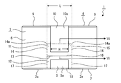
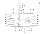
摘子部11は実線状又は破線状の四つの切込線に囲まれた領域として形成されている。四つの切込線は、図3に示すように、左右に延びる第1の切込線13と上下に延びる一対の第2の切込線14、14と左右に延びる第3の切込線15とから成る。
The knob portion 11 is formed as a region surrounded by four cut lines that are solid lines or broken lines. As shown in FIG. 3, the four cut lines include a first cut line 13 extending left and right, a pair of second cut lines 14 and 14 extending vertically, and a third cut line 15 extending left and right. It consists of.
第1の切込線13は押込部12との境界線として形成され、例えば、第1の側面部6を貫通する実線状に形成されている。尚、第1の切込線13は破線状に形成されていてもよい。また、第1の切込線13は、例えば、全体のうち切込が存在しない短い部分が数箇所あるように形成されていてもよく、このように第1の切込線13を形成することにより運搬中等の摘子部11及び押込部12の意図しない押し込み(折り曲げ)が生じ難いと共に摘子部11及び押込部12を小さな力で折り曲げることができ開梱時における作業性の向上を図ることができる。
The first cut line 13 is formed as a boundary line with the pushing portion 12, and is formed in a solid line shape penetrating the first side surface portion 6, for example. The first cut line 13 may be formed in a broken line shape. Moreover, the 1st score line 13 may be formed, for example so that there may be several short parts which do not have a score among the whole, and forms the 1st score line 13 in this way. Therefore, unintentional pushing (bending) of the knob portion 11 and the pushing portion 12 during transportation is difficult to occur, and the knob portion 11 and the pushing portion 12 can be bent with a small force to improve workability at the time of unpacking. Can do.
但し、第1の切込線13が第1の側面部6を貫通された実線状に形成されることにより、開梱時における摘子部11の引き出しに要する力が一層小さくなり、摘子部11の引き出しを容易に行うことができる。また、上記したように、第1の切込線13は押込部12との境界線として形成されているため、第1の切込線13が第1の側面部6を貫通された実線状に形成されることにより、開梱時における押込部12の押し込みに要する力も一層小さくなり、押込部12の押し込みを容易に行うことができる。
However, since the first cutting line 13 is formed in a solid line shape penetrating the first side surface portion 6, the force required to pull out the knob portion 11 at the time of unpacking is further reduced, and the knob portion 11 can be easily pulled out. In addition, as described above, since the first cut line 13 is formed as a boundary line with the pushing portion 12, the first cut line 13 has a solid line shape penetrating the first side surface portion 6. By being formed, the force required to push the pushing portion 12 at the time of unpacking is further reduced, and the pushing portion 12 can be pushed easily.
第2の切込線14、14は下端がそれぞれ第1の切込線13の両端に連続され、左右方向に離隔して平行な状態で形成されている。従って、第2の切込線14、14は粘着テープ10の左右両側縁に平行な状態で位置される。第2の切込線14は、例えば、第1の側面部6を貫通する破線状に形成されている。
The lower end of each of the second cut lines 14 and 14 is connected to both ends of the first cut line 13 and is formed in a parallel state with a separation in the left-right direction. Accordingly, the second cut lines 14 and 14 are positioned in parallel with the left and right side edges of the adhesive tape 10. The 2nd score line 14 is formed in the shape of a broken line which penetrates the 1st side part 6, for example.
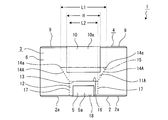
第2の切込線14、14の上端、即ち、押込部12と反対側の一端をそれぞれテープ側切込端14a、14aとすると、テープ側切込端14a、14aの粘着テープ10の幅方向における距離Lは粘着テープ10の幅Hより大きくされ、例えば、距離Lは幅Hより2mm乃至10mm大きくされている。粘着テープ10は長手方向における端部10aが適正状態において摘子部11に貼り付けられるが、この場合において、粘着テープ10の左右両側縁と第2の切込線14、14の間にそれぞれ1mm乃至5mmの間隔(マージン)が形成される。尚、例えば、図4及び図5に示すように、第2の切込線14、14の長さが相違したり少なくとも一方の第2の切込線14、14が傾斜されている等によりテープ側切込端14a、14aの上下方向における位置が異なる場合もあるが、これらの場合においてもテープ側切込端14a、14aの粘着テープ10の幅方向における距離Lは粘着テープ10の幅Hより大きくされている。
If the upper ends of the second cut lines 14 and 14, that is, one end opposite to the pushing portion 12 are tape side cut ends 14 a and 14 a, respectively, the width direction of the adhesive tape 10 at the tape side cut ends 14 a and 14 a The distance L is larger than the width H of the adhesive tape 10. For example, the distance L is 2 mm to 10 mm larger than the width H. The adhesive tape 10 is attached to the knob portion 11 with the end portion 10a in the longitudinal direction being in an appropriate state. In this case, 1 mm is provided between the left and right side edges of the adhesive tape 10 and the second cut lines 14 and 14, respectively. An interval (margin) of 5 to 5 mm is formed. For example, as shown in FIGS. 4 and 5, the length of the second cut lines 14, 14 is different, or at least one of the second cut lines 14, 14 is inclined, etc. The positions of the side cut ends 14a, 14a in the vertical direction may be different. In these cases, the distance L in the width direction of the adhesive tape 10 at the tape side cut ends 14a, 14a is more than the width H of the adhesive tape 10. It has been enlarged.
第3の切込線15は両端がそれぞれ第2の切込線14、14の上端に連続され、第1の側面部6の表ライナー6aには切込を有さず、第1の側面部6の裏ライナー6bのみ又は第1の側面部6の裏ライナー6bと中芯6cに切込を有する実線状又は破線状に形成されている(図6参照)。尚、図6は理解を容易にするために切込の大きさを誇張して示している(以下の図において同じ。)。
Both ends of the third cut line 15 are connected to the upper ends of the second cut lines 14 and 14, respectively, the front liner 6a of the first side face 6 has no cut, and the first side face Only the back liner 6b of 6 or the back liner 6b of the first side surface portion 6 and the center core 6c are formed in a solid line shape or a broken line shape (see FIG. 6). In FIG. 6, the size of the cut is exaggerated for the sake of easy understanding (the same applies to the following drawings).
このように第3の切込線15は裏ライナー6bのみ又は裏ライナー6bと中芯6cに切込を有するように形成されているため、外側へ引き出されるときの折り目として機能する。尚、第3の切込線15は第1の側面部6を貫通する実線状又は破線状に形成されていてもよい。
Thus, since the third cut line 15 is formed so as to have notches only in the back liner 6b or in the back liner 6b and the center core 6c, it functions as a fold when pulled out to the outside. The third cut line 15 may be formed in a solid line shape or a broken line shape penetrating the first side surface portion 6.
押込部12は実線状又は破線状の四つの切込線に囲まれた領域として形成されている。四つの切込線は、図3に示すように、左右に延びる第4の切込線16と上下に延びる一対の第5の切込線17、17と左右に延びる第6の切込線18とから成る。
The pushing portion 12 is formed as a region surrounded by four cut lines that are solid lines or broken lines. As shown in FIG. 3, the four cut lines include a fourth cut line 16 extending left and right, a pair of fifth cut lines 17 and 17 extending vertically, and a sixth cut line 18 extending left and right. It consists of.
第4の切込線16は摘子部11との境界線として形成され第1の切込線13と共有され、例えば、第1の側面部6を貫通する実線状に形成されている。尚、第4の切込線16は破線状に形成されていてもよい。
The 4th cut line 16 is formed as a boundary line with the knob part 11, is shared with the 1st cut line 13, and is formed in the shape of a solid line which penetrates the 1st side part 6, for example. The fourth cut line 16 may be formed in a broken line shape.
第5の切込線17、17は上端がそれぞれ第4の切込線16の両端に連続され、左右方向に離隔して平行な状態で形成されている。従って、第5の切込線17、17は貼着テープ5の左右両側縁に平行な状態で位置される。第5の切込線17は、例えば、第1の側面部6を貫通する破線状に形成されている。
The upper ends of the fifth cut lines 17 and 17 are respectively connected to both ends of the fourth cut line 16, and are formed in a parallel state separated in the left-right direction. Accordingly, the fifth cut lines 17 and 17 are positioned in parallel with the left and right side edges of the adhesive tape 5. The 5th cut line 17 is formed in the shape of a broken line which penetrates the 1st side part 6, for example.
第6の切込線18は押込部12が内側へ押し込まれるときの折り目として機能し、両端がそれぞれ第5の切込線17、17の下端に連続され、、例えば、第1の側面部6の下縁、即ち、第1の側面部6と底面部3の境界部である折曲部分に一致されている。従って、第6の切込線18には予め折り目が付されているため、第6の切込線18には切込が形成されていなくてもよい。
The sixth cut line 18 functions as a fold when the push portion 12 is pushed inward, and both ends are connected to the lower ends of the fifth cut lines 17 and 17, respectively. For example, the first side face portion 6 The lower edge, that is, the bent portion that is the boundary between the first side surface portion 6 and the bottom surface portion 3 is matched. Therefore, since the sixth cut line 18 is creased in advance, the sixth cut line 18 may not be formed with a cut.
このように第6の切込線18に切込が形成されないことにより、第1の側面部6の高い強度を確保することができる。また、押込部12を形成する第6の切込線18が第1の側面部6の下縁に一致されることにより、押込部12の押し込みを容易に行うことができると共に第6の切込線18に実線状又は破線状の切込を形成するための加工工程が不要になり段ボール箱1の製造コストの低減及び製造時間の短縮化を図ることができる。
As described above, since no cut is formed in the sixth cut line 18, high strength of the first side face portion 6 can be ensured. In addition, since the sixth cut line 18 forming the pushing portion 12 is aligned with the lower edge of the first side surface portion 6, the pushing portion 12 can be pushed easily and the sixth cutting line is formed. A processing step for forming a solid line-like or broken-line-like cut in the line 18 becomes unnecessary, and the manufacturing cost and the manufacturing time of the cardboard box 1 can be reduced.
尚、第6の切込線18には切込が形成されていてもよく、この場合に第6の切込線18は、第1の側面部6の表ライナー6aには切込を有さず、第1の側面部6の裏ライナー6bのみ又は第1の側面部6の裏ライナー6bと中芯6cに切込を有する実線状又は破線状に形成される。但し、第6の切込線18は押込部12を押し込み易くするために、表ライナー6aのみ又は表ライナー6aと中芯6cに切込を有する実線状又は破線状に形成されていてもよい。尚、第6の切込線18は第1の側面部6を貫通する破線状に形成されていてもよい。
Note that a cut may be formed in the sixth cut line 18, and in this case, the sixth cut line 18 has a cut in the front liner 6a of the first side face portion 6. Instead, only the back liner 6b of the first side surface portion 6 or the back liner 6b of the first side surface portion 6 and the center core 6c are formed in a solid line shape or a broken line shape. However, the sixth cut line 18 may be formed in a solid line shape or a broken line shape having a cut in only the front liner 6a or the front liner 6a and the center core 6c in order to make the pushing portion 12 easy to push. The sixth cut line 18 may be formed in a broken line shape penetrating the first side surface portion 6.
上記には、押込部12を形成する第6の切込線18が第1の側面部6の下縁に一致された例を示したが、第6の切込線18が第1の側面部6の下縁以外の位置に存在するように構成することも可能である。例えば、図7に示すように、摘子部11と押込部12が第1の側面部6の略中央部に形成されていてもよい。
In the above, an example in which the sixth cut line 18 forming the pushing portion 12 is aligned with the lower edge of the first side surface portion 6 is shown, but the sixth cut line 18 is the first side surface portion. It is also possible to configure to exist at a position other than the lower edge of 6. For example, as shown in FIG. 7, the knob portion 11 and the pushing portion 12 may be formed at a substantially central portion of the first side surface portion 6.
また、摘子部11を形成する第3の切込線15が第1の側面部6の上縁、即ち、第1の側面部6と内側ラップ部8の境界部である折曲部分に一致されていてもよい。
Further, the third cut line 15 forming the knob portion 11 coincides with the upper edge of the first side surface portion 6, that is, the bent portion that is the boundary portion between the first side surface portion 6 and the inner wrap portion 8. May be.
第3の切込線15が第1の側面部6の上縁に一致されることにより、摘子部11の引き出しを容易に行うことができると共に第3の切込線15に実線状又は破線状の切込の形成を省略することも可能であり段ボール箱1の製造コストの低減及び製造時間の短縮化を図ることができる。
By making the third cut line 15 coincide with the upper edge of the first side face part 6, the knob part 11 can be easily pulled out, and the third cut line 15 has a solid line or a broken line. It is also possible to omit the formation of the shape-like cut, and the manufacturing cost and the manufacturing time of the cardboard box 1 can be reduced.
<粘着テープの剥離作業>
次に、粘着テープ10の剥離作業の手順について説明する(図1、図8乃至図14参照)。
<Peeling work of adhesive tape>
Next, the procedure of the peeling work of the adhesive tape 10 is demonstrated (refer FIG. 1, FIG. 8 thru | or FIG. 14).
段ボール箱1の内部に物品が梱包され剥離作業が行われる前の状態においては、図1に示すように、貼着テープ5の長手方向における両側の端部5a、5aがそれぞれ押込部12、12に貼り付けられている。このとき端部5aの左右両側縁が第5の切込線17、17の内側に位置され、端部5aの上縁が第4の切込線16の下側に位置され、端部5aは押込部12を跨がない状態で貼り付けられている。
In the state before the article is packed inside the cardboard box 1 and the peeling operation is performed, as shown in FIG. 1, the end portions 5 a and 5 a on both sides in the longitudinal direction of the sticking tape 5 are the pressing portions 12 and 12, respectively. Is pasted. At this time, the left and right side edges of the end portion 5a are positioned inside the fifth cut lines 17 and 17, the upper edge of the end portion 5a is positioned below the fourth cut line 16, and the end portion 5a is It is affixed in a state where it does not straddle the pushing portion 12.
また、このとき、上記したように、粘着テープ10は長手方向における両側の端部10a、10aが摘子部11、11に貼り付けられている。このとき端部10aの左右両側縁が第2の切込線14、14の内側に位置され、端部10aの下縁が第1の切込線13の上側に位置され、端部10aの左右両側縁と第2の切込線14、14の間及び端部10aの下縁と第1の切込線13の間にそれぞれ間隔が形成され、端部10aは摘子部11を跨がない状態で貼り付けられている。
At this time, as described above, the adhesive tape 10 has the end portions 10a and 10a on both sides in the longitudinal direction attached to the knob portions 11 and 11, respectively. At this time, the left and right side edges of the end portion 10a are positioned inside the second cut lines 14, 14, and the lower edge of the end portion 10a is positioned above the first cut line 13, and the left and right edges of the end portion 10a are Spaces are formed between both side edges and the second cut lines 14 and 14 and between the lower edge of the end portion 10a and the first cut line 13, and the end portion 10a does not straddle the knob portion 11. It is pasted in the state.
上記した状態において、先ず、押込部12を押圧して押込部12を内側へ押し込む(図8参照)。押込部12が内側へ押し込まれるときには、押圧する力によって第5の切込線17、17が切断されると共に第6の切込線18が折り曲げられる。このとき貼着テープ5の端部5aが押込部12とともに内側へ押し込まれる。貼着テープ5の端部5aは押込部12を跨がない状態で貼り付けられているため、押込部12の押込時に貼着テープ5の粘着力が押込部12を押し込む力に対する抵抗になることがなく、押込部12の押し込みを小さな力で円滑に行うことができる。
In the state described above, first, the pushing portion 12 is pressed to push the pushing portion 12 inward (see FIG. 8). When the pushing portion 12 is pushed inward, the fifth cut lines 17 and 17 are cut and the sixth cut line 18 is bent by the pressing force. At this time, the end portion 5 a of the sticking tape 5 is pushed inward together with the pushing portion 12. Since the end portion 5a of the sticking tape 5 is stuck without straddling the pressing portion 12, the adhesive force of the sticking tape 5 becomes a resistance to the force for pressing the pressing portion 12 when the pressing portion 12 is pushed. The pushing portion 12 can be pushed in smoothly with a small force.
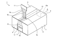
押込部12が内側へ押し込まれると、第1の側面部6における押込部12が存在していた部分に開口19が形成される。
When the pushing portion 12 is pushed inward, an opening 19 is formed in the portion of the first side face portion 6 where the pushing portion 12 was present.
次に、開口19に指を挿入して摘子部11を把持し、摘子部11を外側へ引き出す(図9参照)。摘子部11が外側へ引き出されるときには、引き出す力によって第2の切込線14、14が切断されると共に第3の切込線15が折り曲げられ、粘着テープ10の端部10aも摘子部11とともに外側へ引き出される。
Next, a finger is inserted into the opening 19 to grip the knob part 11, and the knob part 11 is pulled out (see FIG. 9). When the knob part 11 is pulled out, the second cutting lines 14 and 14 are cut and the third cutting line 15 is bent by the pulling force, and the end part 10a of the adhesive tape 10 is also cut into the knob part. 11 is pulled out together.
このとき摘子部11において第2の切込線14、14間の距離Lが粘着テープ10の幅Hより大きくされ、端部10aの下縁と第1の切込線13の間に間隔も形成され、端部10aは摘子部11を跨がない状態で貼り付けられている。従って、摘子部11の引出時に粘着テープ10の粘着力が摘子部11を引き出す力に対する抵抗になることがなく、摘子部11の引き出しを小さな力で円滑に行うことができる。
At this time, the distance L between the second cut lines 14 and 14 in the knob portion 11 is made larger than the width H of the adhesive tape 10, and the distance between the lower edge of the end portion 10 a and the first cut line 13 is also set. The end portion 10 a is formed so as not to straddle the knob portion 11. Therefore, the adhesive force of the adhesive tape 10 does not become resistance to the force for pulling out the knob portion 11 when the knob portion 11 is pulled out, and the knob portion 11 can be pulled out smoothly with a small force.
続いて、引き出した摘子部11を粘着テープ10に沿って引っ張る(図10参照)。摘子部11が引っ張られると、引っ張る力によって表ライナー6aにおける第3の切込線15が切断されて第3の切込線15の上側の部分が粘着テープ10とともに引き剥がされ、さらに外側ラップ部9、9における粘着テープ10が貼り付けられていた部分の表ライナー9a、9aが粘着テープ10とともに引き剥がされていく。尚、図10において梨子地で示した部分は、引き剥がされた後の剥離痕を示している。
Subsequently, the pulled knob portion 11 is pulled along the adhesive tape 10 (see FIG. 10). When the knob part 11 is pulled, the third cutting line 15 in the front liner 6a is cut by the pulling force, and the upper part of the third cutting line 15 is peeled off together with the adhesive tape 10, and further the outer wrap. The surface liners 9 a and 9 a of the portions 9 and 9 where the adhesive tape 10 has been attached are peeled off together with the adhesive tape 10. In addition, the part shown with the pear place in FIG. 10 has shown the peeling trace after peeling.
このとき表ライナー6aと表ライナー9a、9aは厚み方向における全体が中芯に対して剥離されるか、又は、表面部分のみが剥離される。
At this time, the entire front liner 6a and the front liners 9a and 9a in the thickness direction are peeled from the core, or only the surface portion is peeled off.
さらに摘子部11が引っ張られることにより、引き出された摘子部11の側と反対側に位置する第1の側面部6の表ライナー6aが粘着テープ10の反対側の端部10aとともに引き剥がされ、粘着テープ10の全体が段ボール箱1から剥離される。
Further, by pulling the knob part 11, the front liner 6 a of the first side face part 6 located on the opposite side to the drawn knob part 11 side is peeled off together with the opposite end part 10 a of the adhesive tape 10. Then, the entire adhesive tape 10 is peeled from the cardboard box 1.
尚、上記には、粘着テープ10の剥離作業を一方の第1の側面部6側から行う例を示したが、第1の側面部6、6の双方に摘子部11、11と押込部12、12が設けられている場合には、両方の押込部12、12を内側へ押し込んだ後に両方の摘子部11、11を外側へ引き出して粘着テープ10に沿って引っ張ることにより粘着テープ10を剥離することも可能である。
In addition, although the example which performs the peeling operation | work of the adhesive tape 10 from the one 1st side surface part 6 side was shown above, both the 1st side surface parts 6 and 6 have the knob parts 11 and 11 and the pushing part. 12 and 12, the pressure-sensitive adhesive tape 10 is formed by pulling both the push-in portions 11 and 11 outward and pulling them along the pressure-sensitive adhesive tape 10 after the both push-in portions 12 and 12 are pushed inward. It is also possible to peel off.
また、段ボール箱1においては、摘子部11の左右方向における幅が粘着テープ10の幅より大きくされ、摘子部11の左右方向における大きさが大きくされている。従って、図11に示すように、開口19から指100を挿入して摘子部11を引き出そうとするときに、挿入した指100の爪101が第2の切込線14、14に引掛かり難く、また、指100の先端部が左右方向において摘子部11の外側に宛がわれ難いため、指100で摘子部11のみを把持して容易に摘子部11を引き出すことが可能になる。
Also, in the cardboard box 1, the width of the knob portion 11 in the left-right direction is larger than the width of the adhesive tape 10, and the size of the knob portion 11 in the left-right direction is increased. Therefore, as shown in FIG. 11, when the finger 100 is inserted from the opening 19 and the knob portion 11 is to be pulled out, the nail 101 of the inserted finger 100 is not easily caught on the second cut lines 14 and 14. In addition, since the tip of the finger 100 is not easily directed to the outside of the knob part 11 in the left-right direction, it is possible to easily pull out the knob part 11 by gripping only the knob part 11 with the finger 100. .
さらに、段ボール箱1においては、一対の第2の切込線14、14が粘着テープ10の幅方向に直交され、上下に延び平行な状態に形成されている。
Furthermore, in the corrugated cardboard box 1, the pair of second cut lines 14 and 14 are orthogonal to the width direction of the adhesive tape 10, and are formed in a parallel state extending vertically.
従って、第2の切込線14、14間の距離が第2の切込線14、14の長さ方向(上下方向)の何れの位置においても粘着テープ10の幅Hより大きくなり、粘着テープ10の端部10aの先端縁が上下方向において何れの位置に存在しても端部10aが第2の切込線14、14を覆う状態にはならないため、粘着テープ10の貼付位置に拘わらず粘着テープ10の剥離を容易かつ確実に行うことができる。
Accordingly, the distance between the second cut lines 14 and 14 is larger than the width H of the adhesive tape 10 at any position in the length direction (vertical direction) of the second cut lines 14 and 14, and the adhesive tape. Since the end 10a does not cover the second cut lines 14 and 14 regardless of the position of the tip edge of the end 10a in the vertical direction, the end 10a does not cover the second cut lines 14 and 14. The adhesive tape 10 can be easily and reliably peeled off.
上記には、粘着テープ10の端部10aが摘子部11に貼り付けられた例を示したが、例えば、手作業により端部10aが貼り付けられる場合には、端部10aが摘子部11の上側に貼り付けられてしまう可能性がある(図12参照)。
Although the example in which the end portion 10a of the adhesive tape 10 is attached to the knob portion 11 has been described above, for example, when the end portion 10a is attached by hand, the end portion 10a is used as the knob portion. 11 (see FIG. 12).
しかしながら、段ボール箱1にあっては、第2の切込線14、14において、テープ側切込端14a、14aの粘着テープ10の幅方向における距離Lが粘着テープ10の幅Hより大きくされているため、摘子部11を引っ張って第1の側面部6の表ライナー6aを引き剥がしていくときに、引き剥がすに従って次第に幅が小さくなっていく表ライナー6aの左右両側縁が端部10aの下縁に到達せず端部10aの左右両側縁にそれぞれ到達する蓋然性が高い(図13参照)。
However, in the cardboard box 1, the distance L in the width direction of the adhesive tape 10 of the tape-side cut ends 14 a and 14 a is made larger than the width H of the adhesive tape 10 in the second cut lines 14 and 14. Therefore, when pulling the knob part 11 and peeling off the front liner 6a of the first side face part 6, the left and right side edges of the front liner 6a gradually decrease in width as the peeler 10 is peeled off. There is a high probability of reaching the left and right side edges of the end 10a without reaching the lower edge (see FIG. 13).
このとき、端部10aの先端部が表ライナー6aとともに既に引き剥がされており、さらに摘子部11を粘着テープ10に沿って引っ張ることにより粘着テープ10を剥離することができる(図14参照)。尚、図13及び図14において梨子地で示した部分は、引き剥がされた後の剥離痕を示している。
At this time, the tip portion of the end portion 10a has already been peeled off together with the front liner 6a, and the adhesive tape 10 can be peeled by further pulling the knob portion 11 along the adhesive tape 10 (see FIG. 14). . In addition, the part shown with the pear place in FIG.13 and FIG.14 has shown the peeling trace after peeling.
このように、段ボール箱1にあっては、テープ側切込端14a、14aの粘着テープ10の幅方向における距離Lが粘着テープ10の幅Hより大きくされているため、摘子部11を引っ張って第1の側面部6の表ライナー6aを引き剥がしていくときに表ライナー6aの左右両側縁が端部10aの左右両側縁にそれぞれ到達する蓋然性が高い。
Thus, in the cardboard box 1, the distance L in the width direction of the adhesive tape 10 between the tape-side cut ends 14 a and 14 a is larger than the width H of the adhesive tape 10. Thus, when the front liner 6a of the first side surface portion 6 is peeled off, there is a high probability that the left and right side edges of the front liner 6a will reach the left and right side edges of the end portion 10a, respectively.
従って、端部10aが摘子部11に貼り付けられていない場合においても、粘着テープ10の粘着力が粘着テープ10を剥離しようとする力に対する抵抗になり難く、粘着テープ10の貼付位置に拘わらず粘着テープ10を容易に剥離することができる。
Therefore, even when the end portion 10a is not attached to the knob portion 11, the adhesive force of the adhesive tape 10 is unlikely to be a resistance to the force for peeling the adhesive tape 10, and the sticking position of the adhesive tape 10 is limited. The adhesive tape 10 can be easily peeled off.
<変形例>
次に、摘子部又は押込部の各変形例について説明する(図15乃至図25参照)。
<Modification>
Next, each modified example of a knob part or a pushing part is demonstrated (refer FIG. 15 thru | or FIG. 25).
尚、以下に示す摘子部又は押込部の各変形例は、上記した摘子部11又は押込部12と比較して一部の構成が異なることのみが相違するため、摘子部11又は押込部12と比較して異なる部分についてのみ詳細に説明をし、その他の部分については摘子部11又は押込部12における同様の部分に付した符号と同じ符号を付して説明は省略する。
In addition, since each modification of the knob | pick part or the pushing part shown below is different only in a part structure compared with the above-mentioned knob part 11 or the pushing part 12, it is the knob part 11 or pushing. Only a different part compared with the part 12 is demonstrated in detail, About the other part, the code | symbol same as the code | symbol attached | subjected to the same part in the knob part 11 or the pushing part 12 is attached | subjected, and description is abbreviate | omitted.
先ず、第1の変形例に係る摘子部11Aについて説明する(図15及び図16参照)。
First, a knob portion 11A according to a first modification will be described (see FIGS. 15 and 16).
摘子部11Aは第2の切込線14A、14Aが上方へ行くに従って互いに離隔するように傾斜されており、等脚台形状に形成されている。摘子部11Aは第2の切込線14A、14Aにおいて、テープ側切込端14a、14aの粘着テープ10の幅方向における上端間の距離L1が粘着テープ10の幅Hより大きくされており、第2の切込線14A、14Aの下端間の粘着テープ10の幅方向における距離L2が粘着テープ10の幅Hより小さくされている。
The knob part 11A is inclined so as to be separated from each other as the second cut lines 14A and 14A go upward, and is formed in an isosceles trapezoidal shape. In the second cut line 14A, 14A, the knob portion 11A has a distance L1 between the upper ends in the width direction of the adhesive tape 10 of the tape-side cut ends 14a, 14a larger than the width H of the adhesive tape 10, A distance L <b> 2 in the width direction of the adhesive tape 10 between the lower ends of the second score lines 14 </ b> A and 14 </ b> A is made smaller than the width H of the adhesive tape 10.
第2の切込線14A、14Aの下端は、それぞれ第1の切込線13の両端に連続されていてもよく(図15参照)、それぞれ第1の切込線13の両端以外の部分に連続されていてもよく(図16参照)、摘子部11Aは左右方向における大きさが粘着テープ10の幅の大きさに応じて形成されていればよい。
The lower ends of the second score lines 14A and 14A may be respectively connected to both ends of the first score line 13 (see FIG. 15). It may be continuous (refer to Drawing 16), and knob part 11A should just be formed according to the size of the width of adhesive tape 10 in the size in the left-right direction.
第1の側面部6に摘子部11Aが形成された場合においても、粘着テープ10の端部10aが摘子部11Aを跨がない状態で貼付可能であるため、摘子部11Aの引出時に粘着テープ10の粘着力が摘子部11Aを引き出す力に対する抵抗にならず、摘子部11の引き出しを小さな力で円滑に行うことができる。
Even when the knob part 11A is formed on the first side face part 6, since the end part 10a of the adhesive tape 10 can be pasted without straddling the knob part 11A, when the knob part 11A is pulled out. The adhesive force of the adhesive tape 10 does not become resistance to the force for pulling out the knob part 11A, and the knob part 11 can be pulled out smoothly with a small force.
また、摘子部11Aが形成された場合において、粘着テープ10の端部10aが摘子部11の上側に貼り付けられてしまっても、第2の切込線14A、14Aにおいて、テープ側切込端14a、14aの粘着テープ10の幅方向における距離L1が粘着テープ10の幅Hより大きくされているため、摘子部11Aを引っ張って第1の側面部6の表ライナー6aを引き剥がしていくときに表ライナー6aの左右両側縁が端部10aの左右両側縁にそれぞれ到達する蓋然性が高い。
Further, in the case where the knob part 11A is formed, even if the end part 10a of the adhesive tape 10 is affixed to the upper side of the knob part 11, the second cut lines 14A and 14A are cut off on the tape side. Since the distance L1 in the width direction of the adhesive tape 10 between the insertion ends 14a and 14a is made larger than the width H of the adhesive tape 10, the knob 11A is pulled to peel off the front liner 6a of the first side surface 6. There is a high probability that the left and right side edges of the front liner 6a will reach the left and right side edges of the end portion 10a.
従って、端部10aが摘子部11Aに貼り付けられていない場合においても、粘着テープ10の粘着力が粘着テープ10を剥離しようとする力に対する抵抗になり難く、粘着テープ10の貼付位置に拘わらず粘着テープ10を容易に剥離することができる。
Therefore, even when the end portion 10a is not attached to the knob portion 11A, the adhesive force of the adhesive tape 10 is unlikely to be a resistance to the force for peeling the adhesive tape 10, and the sticking position of the adhesive tape 10 is limited. The adhesive tape 10 can be easily peeled off.
尚、上記には、第1の変形例として等脚台形状の摘子部11Aを例として示したが、段ボール箱1においては、第2の切込線14A、14Aの少なくとも上端間、即ち、テープ側切込端14a、14aの粘着テープ10の幅方向における距離L1が粘着テープ10の幅Hより大きくされていればよく、このような構成を満足する摘子部であれば各種の形状に形成することが可能である。
In the above description, the isosceles trapezoidal knob portion 11A is shown as an example as a first modification. In the corrugated cardboard box 1, at least between the upper ends of the second cut lines 14A, 14A, that is, The distance L1 in the width direction of the pressure-sensitive adhesive tape 10 at the tape-side cut ends 14a and 14a only needs to be larger than the width H of the pressure-sensitive adhesive tape 10, and various shapes can be used as long as the knob part satisfies such a configuration. It is possible to form.
次に、第2の変形例に係る摘子部11Bについて説明する(図17及び図18参照)。
Next, a knob portion 11B according to a second modification will be described (see FIGS. 17 and 18).
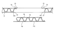
摘子部11Bは第3の切込線15Bが第1の側面部6を貫通する破線状に形成されており、第3の切込線15Bにおいて表ライナー6aの切込20、20、・・・の長さがそれぞれ裏ライナー6bの切込21、21、・・・の長さより短くされている(図17参照)。尚、図17は、第3の切込線15Bを含む拡大水平断面図である。
The knob part 11B is formed in a broken line shape in which the third cut line 15B penetrates the first side face part 6, and the cuts 20, 20,... Of the front liner 6a are formed in the third cut line 15B. The length of each is shorter than the length of the notches 21, 21,... Of the back liner 6b (see FIG. 17). FIG. 17 is an enlarged horizontal sectional view including the third cut line 15B.
このような切込20、20、・・・と切込21、21、・・・の長さが異なる第3の切込線15Bは、図18に示すように、櫛歯状の切込形成装置50によって形成することができる。切込形成装置50には台形状の切断歯51、51、・・・が等間隔に並んで設けられており、切断歯51、51、・・・を第1の側面部6に裏面側から差し込むことにより、一度に切込20、20、・・・と切込21、21、・・・を形成することができる。
The third cut lines 15B having different lengths of the cuts 20, 20,... And the cuts 21, 21,. It can be formed by the device 50. In the cutting forming device 50, trapezoidal cutting teeth 51, 51,... Are arranged at equal intervals, and the cutting teeth 51, 51,. By inserting, notches 20, 20,... And notches 21, 21,.
従って、切込形成装置50を用いることにより容易かつ迅速に第3の切込線15Bを形成することができるため、段ボール箱1の製造の容易化及び製造時間の短縮化による量産性の向上を図ることができる。
Therefore, since the 3rd cut line 15B can be formed easily and rapidly by using the cut formation apparatus 50, improvement of mass-productivity by making manufacture of the corrugated cardboard box 1 and shortening of manufacture time improved. You can plan.
また、第3の切込線15Bにおいて表ライナー6aの切込20、20、・・・の長さがそれぞれ裏ライナー6bの切込21、21、・・・の長さより短くされているため、摘子部11Bが内側へ押し込まれる方向に変位し難く外側へ引き出される方向に変位し易い。さらに、表ライナー6aの切込20、20、・・・の長さがそれぞれ裏ライナー6bの切込21、21、・・・の長さより短くされることにより、摘子部11Bを内側に押し込まれる方向には切り離し難く外側に引き出される方向には切り離し易くなり、段ボール箱1の高い強度を確保した上で粘着テープ10の剥離作業を容易に行うことが可能になる。
Moreover, since the length of the notches 20, 20,... Of the front liner 6a is shorter than the lengths of the notches 21, 21,. It is hard to be displaced in the direction in which the knob portion 11B is pushed inward, and is easily displaced in the direction of being pulled out. Further, the length of the notches 20, 20,... Of the front liner 6a is made shorter than the lengths of the notches 21, 21,. It is difficult to separate in the direction, and it is easy to separate in the direction pulled out, and the adhesive tape 10 can be easily peeled off while ensuring the high strength of the cardboard box 1.
このように摘子部11Bを押し込み難く引き出し易くなるため、運搬中等の意図しない摘子部11Bの押し込みが生じ難いと共に摘子部11Bの引き出しを容易に行うことができる。特に、段ボール箱1にあっては、粘着テープ10が摘子部を跨がない状態で貼り付けられるため、粘着テープ10の粘着力が摘子部の押込方向への抵抗にならず、摘子部が押し込まれ易いと言う不具合を生じるおそれがあるが、押し込みが生じ難い構成の摘子部11Bを形成することにより、このような不具合の発生を防止することが可能になる。
Thus, since the knob part 11B is difficult to be pushed in and easily pulled out, the knob part 11B is not pushed in unintentionally during transportation, and the knob part 11B can be easily pulled out. In particular, in the corrugated cardboard box 1, the adhesive tape 10 is pasted without straddling the knob part, so that the adhesive force of the adhesive tape 10 does not become a resistance in the pushing direction of the knob part, and the knob There is a possibility that a problem that the part is easily pushed in may occur, but by forming the knob part 11B having a configuration in which the push-in is difficult to occur, it is possible to prevent such a problem from occurring.
尚、表ライナー6aの切込の長さがそれぞれ裏ライナー6bの切込の長さより短くされる構成は、第3の切込線15Bの他に、第2の切込線にも適用することが可能である。表ライナー6aの切込の長さがそれぞれ裏ライナー6bの切込の長さより短くされる構成を第2の切込線に適用することにより、摘子部が一層押し込まれ難くなり、運搬中等の意図しない摘子部の押し込みが一層生じ難くなる。また、表ライナー6aの切込の長さがそれぞれ裏ライナー6bの切込の長さより短くされる構成を第2の切込線に適用することにより、摘子部11Bを内側に押し込まれる方向には一層切り離し難く外側に引き出される方向には一層切り離し易くなり、段ボール箱1の一層高い強度を確保した上で粘着テープ10の剥離作業を一層容易に行うことが可能になる。
The configuration in which the cut length of the front liner 6a is shorter than the cut length of the back liner 6b can be applied to the second cut line in addition to the third cut line 15B. Is possible. By applying a configuration in which the length of the cut of the front liner 6a is shorter than the length of the cut of the back liner 6b to the second cut line, the knob portion becomes more difficult to be pushed in, and the intention during transportation, etc. The push-in portion that is not pressed becomes even less likely to occur. Further, by applying a configuration in which the cut length of the front liner 6a is shorter than the cut length of the back liner 6b to the second cut line, in the direction in which the knob portion 11B is pushed inward. It becomes difficult to separate further, and it becomes easier to separate in the direction to be pulled out, and it becomes possible to more easily perform the peeling operation of the adhesive tape 10 while securing a higher strength of the cardboard box 1.
次いで、第3の変形例に係る摘子部11Cについて説明する(図19及び図20参照)。図19は摘子部11Cが引き出される前の状態を示した図であり、図20は摘子部11Cが引き出された状態を概念的に示した図である。
Next, a knob portion 11C according to a third modification will be described (see FIGS. 19 and 20). FIG. 19 is a diagram showing a state before the knob part 11C is pulled out, and FIG. 20 is a diagram conceptually showing a state in which the knob part 11C is pulled out.
摘子部11Cは第2の切込線14C、14Cが第1の側面部6を貫通する破線状に形成されており、表ライナー6aに形成された切込22、22、・・・の位置がそれぞれ裏ライナー6bに形成された切込23、23、・・・の位置より左右方向において外側にされている。従って、摘子部11Cは表ライナー6aにおける第2の切込線14C、14C間の距離が裏ライナー6bにおける第2の切込線14C、14C間の距離より大きくされている。
The knob part 11C is formed in a broken line shape in which the second cut lines 14C, 14C penetrate the first side face part 6, and the positions of the cuts 22, 22, ... formed in the front liner 6a. Are made outside in the left-right direction from the positions of the notches 23, 23,... Formed in the back liner 6b. Accordingly, in the knob portion 11C, the distance between the second cut lines 14C and 14C in the front liner 6a is made larger than the distance between the second cut lines 14C and 14C in the back liner 6b.
切込22、22、・・・と切込23、23、・・・はそれぞれ切断面が左右方向に対して傾斜された状態で形成されている。尚、図19に示す一点鎖線は切込22、22、・・・、23、23、・・・の切断方向を示すための仮想線である。
The notches 22, 22,... And the notches 23, 23,... Are formed with their cut surfaces inclined with respect to the left-right direction. In addition, the dashed-dotted line shown in FIG. 19 is an imaginary line for showing the cutting direction of notches 22, 22, ..., 23,23, ....
切込22、22、・・・と切込23、23、・・・は前後方向へ行くに従って左右方向へ変位するように傾斜されている。
The notches 22, 22,... And the notches 23, 23,... Are inclined so as to be displaced in the left-right direction as they go in the front-rear direction.
尚、第2の切込線14C、14Cは実線状に形成されていてもよい。
The second cut lines 14C and 14C may be formed in a solid line shape.
上記のように摘子部11Cは表ライナー6aにおける第2の切込線14C、14C間の距離が裏ライナー6bにおける第2の切込線14C、14C間の距離より大きくされているため、摘子部11Cの左右方向における表ライナー6a側の距離と裏ライナー6b側の距離との差の部分6x、6xが摘子部11Cに対して外面側から付与される力に対しての受け(抵抗)となる。
Since the distance between the second cut lines 14C and 14C in the front liner 6a is larger than the distance between the second cut lines 14C and 14C in the back liner 6b as described above, The portion 6x, 6x of the difference between the distance on the front liner 6a side and the distance on the back liner 6b side in the left-right direction of the child part 11C is subjected to the force applied to the knob part 11C from the outer surface side (resistance )
従って、摘子部11Cを押し込み難く引き出し易くなるため、運搬中等の意図しない摘子部11Cの押し込みが生じ難いと共に摘子部11Cの引き出しを容易に行うことができる。
Therefore, since the knob part 11C is difficult to be pushed in and easily pulled out, the knob part 11C is not pushed in unintentionally during transportation, and the knob part 11C can be easily pulled out.
第2の切込線14C、14Cが破線状に形成される場合には、第2の切込線14C、14Cを第2の変形例において示した櫛歯状の切込形成装置50を用いて形成することが可能である。第2の切込線14C、14Cを切込形成装置50を用いて形成することにより、段ボール箱1の製造の容易化及び製造時間の短縮化による量産性の向上を図ることができる。
When the second cut lines 14C and 14C are formed in a broken line shape, the second cut lines 14C and 14C are formed using the comb-shaped cut forming apparatus 50 shown in the second modification. It is possible to form. By forming the second cut lines 14C and 14C using the cut forming device 50, it is possible to improve the mass productivity by facilitating the manufacture of the cardboard box 1 and shortening the manufacturing time.
また、第2の切込線14C、14Cを切込形成装置50を用いて形成した場合には、表ライナー6aに形成される切込22、22、・・・の長さが裏ライナー6bに形成される切込23、23、・・・の長さより短くなる。従って、摘子部11Cを一層押し込み難く引き出し易くなるため、運搬中等の意図しない摘子部11Cの押し込みが一層生じ難いと共に摘子部11Cの引き出しを一層容易に行うことができる。
In addition, when the second cut lines 14C and 14C are formed using the cut forming device 50, the lengths of the cuts 22, 22,... Formed on the front liner 6a are the back liner 6b. It becomes shorter than the length of the cuts 23, 23,. Therefore, since the knob part 11C is more difficult to push in and easier to pull out, unintentional pushing of the knob part 11C during transportation or the like is less likely to occur, and the knob part 11C can be pulled out more easily.
次いで、第4の変形例に係る摘子部11Dについて説明する(図21及び図22参照)。図21は摘子部11Dが引き出される前の状態を示した図であり、図22は摘子部11Dが引き出された状態を概念的に示した図である。
Next, a knob portion 11D according to a fourth modification will be described (see FIGS. 21 and 22). FIG. 21 is a diagram showing a state before the knob portion 11D is pulled out, and FIG. 22 is a diagram conceptually showing a state in which the knob portion 11D is pulled out.
摘子部11Dは第2の切込線14D、14Dが破線状に形成されており、表ライナー6a又は表ライナー6aと中芯6cに亘って切込24、24、・・・が形成され、裏ライナー6b又は裏ライナー6bと中芯6cに亘って切込25、25、・・・が形成されている。
In the knob part 11D, the second cut lines 14D, 14D are formed in a broken line shape, and cuts 24, 24,... Are formed across the front liner 6a or the front liner 6a and the core 6c, Cuts 25, 25,... Are formed across the back liner 6b or the back liner 6b and the center core 6c.
摘子部11Dは表ライナー6a側に形成された切込24、24、・・・の位置がそれぞれ裏ライナー6b側に形成された切込25、25、・・・の位置より左右方向において外側にされている。従って、摘子部11Dは表ライナー6aにおける第2の切込線14D、14D間の距離が裏ライナー6bにおける第2の切込線14D、14D間の距離より大きくされている。
The position of the notches 24, 24, ... formed on the front liner 6a side is outside in the left-right direction from the positions of the cuts 25, 25, ... formed on the back liner 6b side. Has been. Accordingly, in the knob portion 11D, the distance between the second cut lines 14D and 14D in the front liner 6a is made larger than the distance between the second cut lines 14D and 14D in the back liner 6b.
切込24、24、・・・と切込25、25、・・・はそれぞれ切断面が左右方向を向く状態で形成されている。尚、図21に示す一点鎖線は切込24、24、・・・、25、25、・・・の切断方向を示すための仮想線である。
The cuts 24, 24,... And the cuts 25, 25,... Are formed with their cut surfaces facing in the left-right direction. 21 is an imaginary line for indicating the cutting direction of the cuts 24, 24,..., 25, 25,.
尚、第2の切込線14D、14Dは実線状に形成されていてもよい。
The second cut lines 14D and 14D may be formed in a solid line shape.
上記のように摘子部11Dは表ライナー6aにおける第2の切込線14D、14D間の距離が裏ライナー6bにおける第2の切込線14D、14D間の距離より大きくされているため、摘子部11Dの左右方向における表ライナー6a側の距離と裏ライナー6b側の距離との差の部分6y、6yが摘子部11Dに対して外面側から付与される力に対しての受け(抵抗)となる。
As described above, since the distance between the second cut lines 14D and 14D in the front liner 6a is larger than the distance between the second cut lines 14D and 14D in the back liner 6b, the knob portion 11D has a knob. The portions 6y and 6y of the difference between the distance on the front liner 6a side and the distance on the back liner 6b side in the left-right direction of the child portion 11D are subjected to the resistance (resistance) applied to the knob portion 11D from the outer surface side. )
従って、摘子部11Dを押し込み難く引き出し易くなるため、運搬中等の意図しない摘子部11Dの押し込みが生じ難いと共に摘子部11Dの引き出しを容易に行うことができる。
Therefore, since the knob part 11D is difficult to be pushed in and easily pulled out, the knob part 11D is not pushed in unintentionally during transportation or the like, and the knob part 11D can be easily pulled out.
次に、第5の変形例に係る摘子部11E及び押込部12Eについて説明する(図23及び図24参照)。
Next, a knob part 11E and a pushing part 12E according to a fifth modification will be described (see FIGS. 23 and 24).
摘子部11Eと押込部12Eはそれぞれ矩形状に形成され、押込部12Eの左右方向における幅が摘子部11Eの左右方向における幅より小さくされ、押込部12Eの面積が摘子部11Eの面積より小さくされている(図23参照)。
The knob part 11E and the pushing part 12E are each formed in a rectangular shape, the width in the left-right direction of the pushing part 12E is made smaller than the width in the left-right direction of the knob part 11E, and the area of the pushing part 12E is the area of the knob part 11E. It is made smaller (see FIG. 23).
このように押込部12Eの面積が摘子部11Eの面積より小さくされているため、押込部12Eが摘子部11Eより押し込み難くなるため、運搬中等の意図しない押込部12Eの押し込みが生じ難くなり、良好な搬送状態を確保することができる。特に、押込部は小さな力で容易に押し込めるようにするような構造にされ易いため、押込部12Eの面積を摘子部11Eの面積より小さくして押込部12Eを押し込み難くすることは、良好な搬送状態を確保する上で有効な手段である。
Thus, since the area of the pushing part 12E is made smaller than the area of the knob part 11E, the pushing part 12E is less likely to be pushed than the knob part 11E, so that the unintended pushing part 12E is not easily pushed in during transportation. A good conveyance state can be ensured. In particular, since the pushing portion is easily structured so as to be pushed easily with a small force, it is preferable to make the pushing portion 12E difficult to push by making the area of the pushing portion 12E smaller than the area of the knob portion 11E. This is an effective means for securing the conveyance state.
尚、第5の変形例において、摘子部11Eと押込部12Eの形状はそれぞれ矩形状に限られることはなく、例えば、図24に示すように、摘子部11Eを等脚台形状に形成して押込部12Eの面積を摘子部11Eの面積より小さくすることも可能である。
In the fifth modification, the shape of the knob portion 11E and the push-in portion 12E is not limited to a rectangular shape. For example, as shown in FIG. 24, the knob portion 11E is formed in an isosceles trapezoid shape. Thus, the area of the pushing portion 12E can be made smaller than the area of the knob portion 11E.
続いて、第6の変形例に係る摘子部11F及び押込部12Fについて説明する(図25参照)。
Subsequently, the knob portion 11F and the pushing portion 12F according to the sixth modification will be described (see FIG. 25).
摘子部11Fと押込部12Fは第2の切込線14F、14Fと第5の切込線17F、17Fがそれぞれ破線状に形成されている。第2の切込線14F、14Fの切込26、26、・・・の長さは第5の切込線17F、17Fの切込27、27、・・・の長さより短くされている。尚、このとき、切込26と切込27の少なくとも一方が表ライナー6aから裏ライナー6cまで貫通された切込として形成され表ライナー6aにおける切込と裏ライナー6cにおける切込の長さが異なる場合には、切込26のうち最も長い切込の長さが切込27のうち最も長い切込の長さより短くされている。
The knob part 11F and the pushing part 12F have second cut lines 14F and 14F and fifth cut lines 17F and 17F formed in broken lines. The lengths of the cuts 26, 26, ... of the second cut lines 14F, 14F are shorter than the lengths of the cuts 27, 27, ... of the fifth cut lines 17F, 17F. At this time, at least one of the notch 26 and the notch 27 is formed as a notch penetrating from the front liner 6a to the back liner 6c, and the length of the notch in the front liner 6a and the notch in the back liner 6c are different. In this case, the longest cut length of the cuts 26 is shorter than the longest cut length of the cuts 27.
従って、摘子部11Fが押し込み難くされ押込部12Fが押し込み易くされるため、運搬中等の意図しない摘子部11Fの押し込みが生じ難くなり良好な搬送状態を確保することができると共に粘着テープ10の開梱作業に際して押込部12Fを容易に押し込むことができ開梱作業における作業性の向上を図ることができる。
Accordingly, the pusher part 11F is difficult to be pushed in and the pusher part 12F is made easy to push in. Therefore, the pusher part 11F is not pushed in unintentionally during transportation and the like, and a good conveyance state can be secured and the adhesive tape 10 can be opened. The pushing portion 12F can be easily pushed during the bundling operation, and the workability in the unpacking operation can be improved.
<他の例>
以下に、摘子部や押込部やこれらに関連する部分における他の例について説明する(図26乃至図30参照)。
<Other examples>
Hereinafter, other examples of the knob part, the push-in part, and the parts related thereto will be described (see FIGS. 26 to 30).
尚、以下に示す他の例は、上記した摘子部11又は押込部12と比較して一部の構成が異なり又は一部の構成が追加されることのみが相違するため、摘子部11又は押込部12と比較して異なる部分についてのみ詳細に説明をし、その他の部分については摘子部11又は押込部12における同様の部分に付した符号と同じ符号を付して説明は省略する。
In addition, since the other examples shown below are different from the above-described knob part 11 or the pushing part 12 in that some of the configurations are different or only a part of the configuration is added, the knob part 11 Or only a different part compared with the pushing part 12 is demonstrated in detail, About the other part, the code | symbol same as the code | symbol attached | subjected to the same part in the knob part 11 or the pushing part 12 is attached | subjected, and description is abbreviate | omitted. .
第1の例としては、第1の側面部6における第2の切込線14、14の上側にそれぞれ補助切込線28、28が形成された例である(図26参照)。
As a first example, auxiliary cut lines 28 and 28 are formed above the second cut lines 14 and 14 in the first side surface portion 6, respectively (see FIG. 26).
補助切込線28、28は上下方向に延びる実線状に形成され、下端がそれぞれ第2の切込線14、14の上端に一致され又は近傍に位置されている。補助切込線28、28は上端がそれぞれ粘着テープ10の左右両側縁の左右方向における外側に位置されている。
The auxiliary cut lines 28, 28 are formed in a solid line extending in the vertical direction, and the lower ends thereof are aligned with or located in the vicinity of the upper ends of the second cut lines 14, 14, respectively. The upper ends of the auxiliary cut lines 28 and 28 are positioned outside the left and right side edges of the adhesive tape 10 in the left and right direction.
補助切込線28、28は表ライナー6aの厚み方向における全体又は表ライナー6aの表面部分のみに形成されている。
The auxiliary score lines 28 and 28 are formed in the whole thickness direction of the front liner 6a or only on the surface portion of the front liner 6a.
補助切込線28、28が形成される場合には、粘着テープ10の端部10aが摘子部11の上側に貼り付けられた状態において特に有効であり、摘子部11を引っ張って表ライナー6aを引き剥がしていくときに表ライナー6aにおける左右の破断部分が補助切込線28、28に案内され、表ライナー6aにおける補助切込線28、28間の部分が引き剥がされていく(図27参照)。補助切込線28、28の上端まで表ライナー6aが引き剥がされたときには粘着テープ10の端部10aにおける先端部が表ライナー6aとともに引き剥がされており、さらに摘子部11が引っ張られることにより引き剥がすに従って次第に幅が小さくなっていく表ライナー6aの左右両側縁が端部10aの下縁に到達せず端部10aの左右両側縁にそれぞれ到達する。
When the auxiliary cut lines 28 and 28 are formed, it is particularly effective when the end portion 10a of the adhesive tape 10 is attached to the upper side of the knob portion 11, and the tab liner 11 is pulled to pull the front liner. When the 6a is peeled off, the left and right broken portions in the front liner 6a are guided to the auxiliary cut lines 28, 28, and the portion between the auxiliary cut lines 28, 28 in the front liner 6a is peeled off (FIG. 27). When the front liner 6a is peeled off to the upper ends of the auxiliary cut lines 28, 28, the tip of the end portion 10a of the adhesive tape 10 is peeled off together with the front liner 6a, and the knob portion 11 is further pulled. The left and right side edges of the front liner 6a that gradually decrease in width as they are peeled off do not reach the lower edge of the end portion 10a but reach the left and right side edges of the end portion 10a.
従って、さらに摘子部11を粘着テープ10に沿って引っ張ることにより粘着テープ10を表ライナー6aとともに剥離することができる。
Therefore, the adhesive tape 10 can be peeled off together with the front liner 6a by further pulling the knob part 11 along the adhesive tape 10.
このように補助切込線28、28が形成された段ボール箱1においては、端部10aが摘子部11に貼り付けられていない場合においても、粘着テープ10の粘着力が粘着テープ10を剥離しようとする力に対する抵抗になり難く、粘着テープ10の貼付位置に拘わらず粘着テープ10を容易に剥離することができる。
In the corrugated cardboard box 1 in which the auxiliary cut lines 28 and 28 are thus formed, the adhesive force of the adhesive tape 10 peels off the adhesive tape 10 even when the end portion 10a is not attached to the knob portion 11. The adhesive tape 10 can be easily peeled off regardless of the position where the adhesive tape 10 is applied.
また、補助切込線28、28は表ライナー6aの厚み方向における全体又は表ライナー6aの表面部分のみに形成され第1の側面部6を貫通する切込ではないため、補助切込線28、28を形成することにより第1の側面部6の強度が大きく低下することはなく、補助切込線28、28を形成することにより段ボール箱1の十分な強度を確保した上で粘着テープ10を容易に剥離することができる。
Further, since the auxiliary score lines 28, 28 are not formed in the entire thickness direction of the front liner 6a or only on the surface portion of the front liner 6a and do not penetrate the first side surface portion 6, the auxiliary score lines 28, By forming 28, the strength of the first side face portion 6 is not greatly reduced, and by forming the auxiliary cut lines 28, 28, the adhesive tape 10 is secured after securing sufficient strength of the cardboard box 1. It can be easily peeled off.
一方、第1の例として、補助切込線28、28に代えて傾斜する補助切込線28A、28Aを形成することも可能である(図28参照)。
On the other hand, as a first example, it is also possible to form auxiliary cutting lines 28A and 28A that are inclined instead of the auxiliary cutting lines 28 and 28 (see FIG. 28).
補助切込線28A、28Aは上方へ行くに従って互いに近付くように傾斜され、下端がそれぞれ第2の切込線14、14の上端に一致され又は近傍に位置されている。補助切込線28A、28Aは上端がそれぞれ粘着テープ10の左右両側縁に一致又は左右両側縁の左右方向における内側に位置されている。
The auxiliary cut lines 28A and 28A are inclined so as to approach each other as they go upward, and the lower ends thereof are aligned with or located in the vicinity of the upper ends of the second cut lines 14 and 14, respectively. The auxiliary cut lines 28A, 28A have upper ends that are respectively coincident with the left and right side edges of the adhesive tape 10, or are located inside the left and right side edges in the left and right direction.
補助切込線28A、28Aは表ライナー6aの厚み方向における全体又は表ライナー6aの表面部分のみに形成されている。
The auxiliary score lines 28A and 28A are formed in the whole thickness direction of the front liner 6a or only on the surface portion of the front liner 6a.
補助切込線28A、28Aが形成される場合にも、粘着テープ10の端部10aが摘子部11の上側に貼り付けられた状態において特に有効であり、摘子部11を引っ張って表ライナー6aを引き剥がしていくときに表ライナー6aにおける左右の破断部分が補助切込線28A、28Aに案内され、表ライナー6aにおける補助切込線28A、28A間の部分が引き剥がされていく。補助切込線28A、28A間の部分が引き剥がされたときには、表ライナー6aにおける左右の破断部分が補助切込線28A、28Aに案内されるため、表ライナー6aの左右両側縁が端部10aの左右両側縁にそれぞれ到達する。このとき粘着テープ10の端部10aにおける先端部が表ライナー6aとともに引き剥がされており、さらに摘子部11が引っ張られることにより粘着テープ10を表ライナー6aとともに剥離することができる。
Even when the auxiliary cut lines 28A and 28A are formed, it is particularly effective in a state where the end portion 10a of the adhesive tape 10 is attached to the upper side of the knob portion 11, and the table liner is pulled by pulling the knob portion 11. When the 6a is peeled off, the left and right broken portions in the front liner 6a are guided to the auxiliary cut lines 28A and 28A, and the portion between the auxiliary cut lines 28A and 28A in the front liner 6a is peeled off. When the portion between the auxiliary cut lines 28A and 28A is peeled off, the left and right broken portions of the front liner 6a are guided to the auxiliary cut lines 28A and 28A, so that both left and right edges of the front liner 6a are the end portions 10a. Reach the left and right side edges respectively. At this time, the tip portion of the end portion 10a of the adhesive tape 10 is peeled off together with the front liner 6a, and the adhesive tape 10 can be peeled off together with the front liner 6a by further pulling the knob portion 11.
このように補助切込線28A、28Aが形成された段ボール箱1においては、端部10aが摘子部11に貼り付けられていない場合においても、粘着テープ10の粘着力が粘着テープ10を剥離しようとする力に対する抵抗になり難く、粘着テープ10の貼付位置に拘わらず粘着テープ10を容易に剥離することができる。
Thus, in the corrugated cardboard box 1 in which the auxiliary score lines 28A and 28A are formed, the adhesive force of the adhesive tape 10 peels off the adhesive tape 10 even when the end portion 10a is not attached to the knob portion 11. The adhesive tape 10 can be easily peeled off regardless of the position where the adhesive tape 10 is applied.
また、表ライナー6aにおける左右の破断部分が傾斜された補助切込線28A、28Aに案内されて左右両側縁が端部10aの左右両側縁にそれぞれ到達するため、粘着テープ10の貼付位置に拘わらず粘着テープ10を確実に剥離することができる。
Further, since the left and right side edges reach the left and right side edges of the end portion 10a as the left and right broken parts of the front liner 6a are guided by the inclined auxiliary cut lines 28A and 28A, respectively, the sticking position of the adhesive tape 10 is concerned. The adhesive tape 10 can be reliably peeled.
さらに、補助切込線28A、28Aは表ライナー6aの厚み方向における全体又は表ライナー6aの表面部分のみに形成され第1の側面部6を貫通する切込ではないため、補助切込線28A、28Aを形成することにより第1の側面部6の強度が大きく低下することはなく、補助切込線28A、28Aを形成することにより段ボール箱1の十分な強度を確保した上で粘着テープ10を容易に剥離することができる。
Further, since the auxiliary score lines 28A, 28A are not the slits formed in the entire thickness direction of the table liner 6a or only on the surface portion of the table liner 6a and penetrating the first side surface portion 6, the auxiliary score lines 28A, By forming 28A, the strength of the first side surface portion 6 is not greatly reduced. By forming the auxiliary cut lines 28A, 28A, the adhesive tape 10 is secured after securing sufficient strength of the cardboard box 1. It can be easily peeled off.
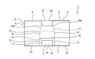
第2の例としては、第1の側面部6に粘着テープ10と貼着テープ5をそれぞれ剥離するための摘子部11、11と押込部12、12が形成された例である(図29参照)。
As a 2nd example, the knob | pick parts 11 and 11 and the pushing parts 12 and 12 for peeling the adhesive tape 10 and the sticking tape 5 respectively are formed in the 1st side part 6 (FIG. 29). reference).
第1の側面部6には上側に摘子部11と押込部12が形成され、その下側にも摘子部11と押込部12が形成されている。上側に位置された摘子部11と押込部12は粘着テープ10の剥離用であり、下側に位置された摘子部11と押込部12は貼着テープ5の剥離用である。尚、下側に位置された摘子部11と押込部12は押込部12と摘子部11が順に上下に連続して形成されている。
The knob part 11 and the pushing part 12 are formed on the upper side of the first side face part 6, and the knob part 11 and the pushing part 12 are also formed on the lower side. The knob part 11 and the pressing part 12 positioned on the upper side are for peeling the adhesive tape 10, and the knob part 11 and the pressing part 12 positioned on the lower side are for peeling the adhesive tape 5. Note that the pusher portion 11 and the pusher portion 12 located on the lower side are formed such that the pusher portion 12 and the pusher portion 11 are successively arranged in the vertical direction.
段ボール箱1において、上側に位置された摘子部11と押込部12を用いて粘着テープ10を剥離すると共に下側に位置された押込部12と摘子部11を用いて貼着テープ5を剥離することにより、粘着テープ10と貼着テープ5の剥離作業を何れも容易に行うことができ、例えば、段ボール箱1を折り畳んだり廃棄したりするときに便利である。
In the corrugated cardboard box 1, the adhesive tape 10 is peeled off using the pusher portion 11 and the pusher portion 12 positioned on the upper side, and the adhesive tape 5 is attached using the pusher portion 12 and the pusher portion 11 located on the lower side. By peeling off, both the adhesive tape 10 and the adhesive tape 5 can be easily peeled off, which is convenient, for example, when the cardboard box 1 is folded or discarded.
また、第2の例として、粘着テープ10と貼着テープ5をそれぞれ剥離するために、第1の側面部6に一つの摘子部11と一つの押込部12から成る兼用部29を形成することも可能である(図30参照)。
As a second example, in order to separate the adhesive tape 10 and the adhesive tape 5 from each other, a combined portion 29 composed of one knob portion 11 and one pushing portion 12 is formed on the first side surface portion 6. It is also possible (see FIG. 30).
兼用部29は上下に連続して形成された第1の部分29aと第2の部分29bから成り、第1の部分29aと第2の部分29bの一方が摘子部11として機能し他方が押込部12として機能する。粘着テープ10を剥離するときには上側に位置された第1の部分29aが摘子部11として機能し下側に位置された第2の部分29bが押込部12として機能する。貼着テープ5を剥離するときには上側に位置された第1の部分29aが押込部12として機能し下側に位置された第2の部分29bが摘子部11として機能する。
The combined portion 29 is composed of a first portion 29a and a second portion 29b formed continuously in the vertical direction, and one of the first portion 29a and the second portion 29b functions as the knob portion 11 and the other is pushed in. It functions as the unit 12. When the adhesive tape 10 is peeled off, the first portion 29a positioned on the upper side functions as the knob portion 11, and the second portion 29b positioned on the lower side functions as the pushing portion 12. When the sticking tape 5 is peeled off, the first portion 29 a positioned on the upper side functions as the push-in portion 12, and the second portion 29 b positioned on the lower side functions as the knob portion 11.
従って、粘着テープ10を剥離するときは、先ず、押込部12として機能する第2の部分29bを押し込み、次に、摘子部11として機能する第1の部分29aを引き出し、引き出した29aを粘着テープ10に沿って引っ張ることにより表ライナー6aとともに粘着テープ10を剥離する。一方、貼着テープ5を剥離するときは、先ず、押込部12として機能する第1の部分29aを押し込み、次に、摘子部11として機能する第2の部分29bを引き出し、引き出した29aを貼着テープ5に沿って引っ張ることにより表ライナー6aとともに貼着テープ5を剥離する。
Therefore, when the adhesive tape 10 is peeled off, first, the second portion 29b that functions as the push-in portion 12 is pushed in, then the first portion 29a that functions as the knob portion 11 is pulled out, and the pulled-out 29a is adhesively bonded. By pulling along the tape 10, the adhesive tape 10 is peeled off together with the front liner 6a. On the other hand, when the adhesive tape 5 is peeled off, first, the first portion 29a that functions as the push-in portion 12 is pushed, and then the second portion 29b that functions as the knob portion 11 is pulled out, and the pulled-out 29a is pulled out. By pulling along the sticking tape 5, the sticking tape 5 is peeled off together with the front liner 6a.
上記のように兼用部29が形成された場合においては、上側に位置された第1の部分29aと下側に位置された第2の部分29bを用いて粘着テープ10と貼着テープ5を剥離することにより、粘着テープ10と貼着テープ5の剥離作業を何れも容易に行うことができ、例えば、段ボール箱1を折り畳んだり廃棄したりするときに便利である。
When the dual-purpose portion 29 is formed as described above, the adhesive tape 10 and the adhesive tape 5 are peeled off using the first portion 29a positioned on the upper side and the second portion 29b positioned on the lower side. By doing so, it is possible to easily perform the peeling operation of the adhesive tape 10 and the sticking tape 5, which is convenient, for example, when the cardboard box 1 is folded or discarded.
また、兼用部29が形成された場合には、摘子部11又は押込部12として機能する部分が一つずつであるため、その分、第1の側面部6の高い強度が確保され、段ボール箱1の全体としての高い強度を確保することができる。
In addition, when the dual-purpose portion 29 is formed, there is one portion that functions as the knob portion 11 or the push-in portion 12, so that the high strength of the first side surface portion 6 is ensured accordingly, and the corrugated cardboard High strength as a whole of the box 1 can be ensured.
<その他>
上記には、第1の切込線乃至第6の切込線が何れも直線状に形成された例を示したが、第1の切込線乃至第6の切込線は直線状に限られることはなく、第1の切込線乃至第6の切込線を必要に応じて曲線状に形成することも可能であり、また、直線と曲線の組み合わせの形状に形成することも可能である。
<Others>
In the above example, the first through sixth cut lines are all formed in a straight line. However, the first through sixth cut lines are limited to a straight line. The first to sixth cut lines can be formed in a curved shape as necessary, or can be formed in a combination of a straight line and a curved line. is there.
また、第1の切込線乃至第6の切込線は必要に応じて左右方向又は上下方向に対して傾斜されていてもよい。
Further, the first through sixth cut lines may be inclined with respect to the left-right direction or the up-down direction as necessary.
さらに、第1の切込線乃至第6の切込線は、これらのうちの連続する切込線が直線状と曲線状の組み合わせ又は曲線状と曲線状の組み合わせの角張った部分のない1本の線として形成されていてもよい。例えば、直線状の第1の切込線と曲線状の第2の切込線が1本の線として形成され、中間の所定の点を基準として一方の切込線が第1の切込線として形成され他方の切込線が第2の切込線として形成されていてもよい。
Further, the first through sixth cut lines are one in which the continuous cut lines of these are a combination of a straight line and a curved line or a combination of a curved line and a curved line without an angular portion. It may be formed as a line. For example, a linear first score line and a curved second score line are formed as one line, and one score line is defined as a first score line based on a predetermined intermediate point. The other cut line may be formed as the second cut line.