WO2015178351A1 - 非水系二次電池用セパレータ、その製造方法及び非水系二次電池 - Google Patents
非水系二次電池用セパレータ、その製造方法及び非水系二次電池 Download PDFInfo
- Publication number
- WO2015178351A1 WO2015178351A1 PCT/JP2015/064224 JP2015064224W WO2015178351A1 WO 2015178351 A1 WO2015178351 A1 WO 2015178351A1 JP 2015064224 W JP2015064224 W JP 2015064224W WO 2015178351 A1 WO2015178351 A1 WO 2015178351A1
- Authority
- WO
- WIPO (PCT)
- Prior art keywords
- separator
- porous layer
- secondary battery
- porous
- aqueous secondary
- Prior art date
- Legal status (The legal status is an assumption and is not a legal conclusion. Google has not performed a legal analysis and makes no representation as to the accuracy of the status listed.)
- Ceased
Links
Images
Classifications
-
- H—ELECTRICITY
- H01—ELECTRIC ELEMENTS
- H01M—PROCESSES OR MEANS, e.g. BATTERIES, FOR THE DIRECT CONVERSION OF CHEMICAL ENERGY INTO ELECTRICAL ENERGY
- H01M50/00—Constructional details or processes of manufacture of the non-active parts of electrochemical cells other than fuel cells, e.g. hybrid cells
- H01M50/40—Separators; Membranes; Diaphragms; Spacing elements inside cells
- H01M50/489—Separators, membranes, diaphragms or spacing elements inside the cells, characterised by their physical properties, e.g. swelling degree, hydrophilicity or shut down properties
-
- H—ELECTRICITY
- H01—ELECTRIC ELEMENTS
- H01M—PROCESSES OR MEANS, e.g. BATTERIES, FOR THE DIRECT CONVERSION OF CHEMICAL ENERGY INTO ELECTRICAL ENERGY
- H01M50/00—Constructional details or processes of manufacture of the non-active parts of electrochemical cells other than fuel cells, e.g. hybrid cells
- H01M50/40—Separators; Membranes; Diaphragms; Spacing elements inside cells
- H01M50/403—Manufacturing processes of separators, membranes or diaphragms
-
- H—ELECTRICITY
- H01—ELECTRIC ELEMENTS
- H01M—PROCESSES OR MEANS, e.g. BATTERIES, FOR THE DIRECT CONVERSION OF CHEMICAL ENERGY INTO ELECTRICAL ENERGY
- H01M10/00—Secondary cells; Manufacture thereof
- H01M10/05—Accumulators with non-aqueous electrolyte
- H01M10/052—Li-accumulators
- H01M10/0525—Rocking-chair batteries, i.e. batteries with lithium insertion or intercalation in both electrodes; Lithium-ion batteries
-
- H—ELECTRICITY
- H01—ELECTRIC ELEMENTS
- H01M—PROCESSES OR MEANS, e.g. BATTERIES, FOR THE DIRECT CONVERSION OF CHEMICAL ENERGY INTO ELECTRICAL ENERGY
- H01M50/00—Constructional details or processes of manufacture of the non-active parts of electrochemical cells other than fuel cells, e.g. hybrid cells
- H01M50/40—Separators; Membranes; Diaphragms; Spacing elements inside cells
- H01M50/409—Separators, membranes or diaphragms characterised by the material
- H01M50/411—Organic material
- H01M50/414—Synthetic resins, e.g. thermoplastics or thermosetting resins
- H01M50/417—Polyolefins
-
- H—ELECTRICITY
- H01—ELECTRIC ELEMENTS
- H01M—PROCESSES OR MEANS, e.g. BATTERIES, FOR THE DIRECT CONVERSION OF CHEMICAL ENERGY INTO ELECTRICAL ENERGY
- H01M50/00—Constructional details or processes of manufacture of the non-active parts of electrochemical cells other than fuel cells, e.g. hybrid cells
- H01M50/40—Separators; Membranes; Diaphragms; Spacing elements inside cells
- H01M50/409—Separators, membranes or diaphragms characterised by the material
- H01M50/411—Organic material
- H01M50/414—Synthetic resins, e.g. thermoplastics or thermosetting resins
- H01M50/426—Fluorocarbon polymers
-
- H—ELECTRICITY
- H01—ELECTRIC ELEMENTS
- H01M—PROCESSES OR MEANS, e.g. BATTERIES, FOR THE DIRECT CONVERSION OF CHEMICAL ENERGY INTO ELECTRICAL ENERGY
- H01M50/00—Constructional details or processes of manufacture of the non-active parts of electrochemical cells other than fuel cells, e.g. hybrid cells
- H01M50/40—Separators; Membranes; Diaphragms; Spacing elements inside cells
- H01M50/409—Separators, membranes or diaphragms characterised by the material
- H01M50/443—Particulate material
-
- H—ELECTRICITY
- H01—ELECTRIC ELEMENTS
- H01M—PROCESSES OR MEANS, e.g. BATTERIES, FOR THE DIRECT CONVERSION OF CHEMICAL ENERGY INTO ELECTRICAL ENERGY
- H01M50/00—Constructional details or processes of manufacture of the non-active parts of electrochemical cells other than fuel cells, e.g. hybrid cells
- H01M50/40—Separators; Membranes; Diaphragms; Spacing elements inside cells
- H01M50/409—Separators, membranes or diaphragms characterised by the material
- H01M50/449—Separators, membranes or diaphragms characterised by the material having a layered structure
-
- H—ELECTRICITY
- H01—ELECTRIC ELEMENTS
- H01M—PROCESSES OR MEANS, e.g. BATTERIES, FOR THE DIRECT CONVERSION OF CHEMICAL ENERGY INTO ELECTRICAL ENERGY
- H01M50/00—Constructional details or processes of manufacture of the non-active parts of electrochemical cells other than fuel cells, e.g. hybrid cells
- H01M50/40—Separators; Membranes; Diaphragms; Spacing elements inside cells
- H01M50/409—Separators, membranes or diaphragms characterised by the material
- H01M50/449—Separators, membranes or diaphragms characterised by the material having a layered structure
- H01M50/457—Separators, membranes or diaphragms characterised by the material having a layered structure comprising three or more layers
-
- H—ELECTRICITY
- H01—ELECTRIC ELEMENTS
- H01M—PROCESSES OR MEANS, e.g. BATTERIES, FOR THE DIRECT CONVERSION OF CHEMICAL ENERGY INTO ELECTRICAL ENERGY
- H01M50/00—Constructional details or processes of manufacture of the non-active parts of electrochemical cells other than fuel cells, e.g. hybrid cells
- H01M50/40—Separators; Membranes; Diaphragms; Spacing elements inside cells
- H01M50/46—Separators, membranes or diaphragms characterised by their combination with electrodes
-
- H—ELECTRICITY
- H01—ELECTRIC ELEMENTS
- H01M—PROCESSES OR MEANS, e.g. BATTERIES, FOR THE DIRECT CONVERSION OF CHEMICAL ENERGY INTO ELECTRICAL ENERGY
- H01M50/00—Constructional details or processes of manufacture of the non-active parts of electrochemical cells other than fuel cells, e.g. hybrid cells
- H01M50/40—Separators; Membranes; Diaphragms; Spacing elements inside cells
- H01M50/463—Separators, membranes or diaphragms characterised by their shape
- H01M50/469—Separators, membranes or diaphragms characterised by their shape tubular or cylindrical
-
- Y—GENERAL TAGGING OF NEW TECHNOLOGICAL DEVELOPMENTS; GENERAL TAGGING OF CROSS-SECTIONAL TECHNOLOGIES SPANNING OVER SEVERAL SECTIONS OF THE IPC; TECHNICAL SUBJECTS COVERED BY FORMER USPC CROSS-REFERENCE ART COLLECTIONS [XRACs] AND DIGESTS
- Y02—TECHNOLOGIES OR APPLICATIONS FOR MITIGATION OR ADAPTATION AGAINST CLIMATE CHANGE
- Y02E—REDUCTION OF GREENHOUSE GAS [GHG] EMISSIONS, RELATED TO ENERGY GENERATION, TRANSMISSION OR DISTRIBUTION
- Y02E60/00—Enabling technologies; Technologies with a potential or indirect contribution to GHG emissions mitigation
- Y02E60/10—Energy storage using batteries
-
- Y—GENERAL TAGGING OF NEW TECHNOLOGICAL DEVELOPMENTS; GENERAL TAGGING OF CROSS-SECTIONAL TECHNOLOGIES SPANNING OVER SEVERAL SECTIONS OF THE IPC; TECHNICAL SUBJECTS COVERED BY FORMER USPC CROSS-REFERENCE ART COLLECTIONS [XRACs] AND DIGESTS
- Y02—TECHNOLOGIES OR APPLICATIONS FOR MITIGATION OR ADAPTATION AGAINST CLIMATE CHANGE
- Y02P—CLIMATE CHANGE MITIGATION TECHNOLOGIES IN THE PRODUCTION OR PROCESSING OF GOODS
- Y02P70/00—Climate change mitigation technologies in the production process for final industrial or consumer products
- Y02P70/50—Manufacturing or production processes characterised by the final manufactured product
Definitions
- the present invention relates to a separator for a non-aqueous secondary battery, a manufacturing method thereof, and a non-aqueous secondary battery.
- Non-aqueous secondary batteries represented by lithium ion secondary batteries are widely used as power sources for portable electronic devices such as notebook computers, mobile phones, digital cameras, and camcorders.
- a technique for improving the adhesion between the electrode and the separator has been proposed.
- a separator having a porous layer containing a polyvinylidene fluoride resin on a substrate made of a polyolefin microporous film or the like is known (see, for example, Patent Documents 1 to 4).
- Patent Documents 1 to 4 When this separator is pressed or hot pressed over the electrode, it adheres well to the electrode through the porous layer, so that the cycle life of the battery can be improved.
- JP 2004-356102 A International Publication No. 2005/049318 Japanese Patent No. 4988972 JP 2013-54972 A
- the polyvinylidene fluoride-based resin is a resin that is easily charged
- the porous layer containing the polyvinylidene fluoride-based resin is easily charged with static electricity, and the separator having the porous layer may have poor handling properties.
- the separator having the porous layer may have poor handling properties.
- a separator with high wettability of the electrolytic solution is preferable in order to impregnate the separator with the electrolytic solution in a short time and with high uniformity.
- An object of the embodiment of the present invention is to provide a separator for a non-aqueous secondary battery that realizes excellent handling properties and high affinity with an electrolyte in a well-balanced manner. Furthermore, an embodiment of the present invention aims to provide a non-aqueous secondary battery with high production efficiency.
- a non-aqueous secondary battery comprising a porous layer having a structure in which a large number of cells opened in a row are arranged adjacent to each other in the plane direction of the porous layer, and the water contact angle is 115 ° to 140 ° Separator.
- the porous layer further includes a surfactant having an HLB value of 5.0 to 8.0, and the polyvinylidene fluoride resin and the surfactant are mixed in the porous layer.
- the separator for a nonaqueous secondary battery according to any one of [1] to [5].
- the mass ratio of the polyvinylidene fluoride-based resin and the surfactant is 99.9: 0.1 to 95.0: 5.0.
- Separator for water-based secondary battery [8]
- the nonaqueous system according to any one of [1] to [7], wherein a peel strength between the porous substrate and the porous layer is 0.1 N / cm to 2.0 N / cm. Secondary battery separator.
- a separator for a non-aqueous secondary battery that realizes excellent handling properties and high affinity with an electrolyte in a well-balanced manner. Furthermore, according to the embodiment of the present invention, a non-aqueous secondary battery is provided with high manufacturing efficiency.
- a numerical range indicated using “to” indicates a range including the numerical values described before and after “to” as the minimum value and the maximum value, respectively.
- machine direction means the long direction in the long porous substrate and separator
- width direction means the direction orthogonal to the “machine direction”.
- machine direction is also referred to as “MD direction”
- TD direction width direction
- a separator for a non-aqueous secondary battery according to the present disclosure includes a porous base material containing a thermoplastic resin, and a polyvinylidene fluoride system provided on one or both surfaces of the porous base material. It is a porous layer containing resin, and has a structure in which a large number of cells opened in the surface vertical direction of the porous layer are arranged adjacent to each other in the surface direction of the porous layer (hereinafter also referred to as “honeycomb structure”). And a porous layer having a water contact angle of 115 ° to 140 °.
- the porous layer is a layer that exists as an outermost layer of the separator and is in contact with the electrode.
- the separator of the present disclosure is a separator having a porous layer containing a polyvinylidene fluoride-based resin on at least one surface of a porous substrate containing a thermoplastic resin, and has a good balance between excellent handling properties and high affinity with an electrolytic solution. Realize. According to the separator of the present disclosure, it is possible to suppress the generation of defective products when the battery element is manufactured by overlapping and winding the separator and the electrode, and the manufacturing efficiency of the battery can be improved.
- the porous layer containing the polyvinylidene fluoride resin has a honeycomb structure and the contact angle of water is 115 ° to 140 °, the porous layer is hardly charged with static electricity and electrolyzed.
- the wettability of the surface of the porous layer to the liquid is high. Therefore, it is considered that when the battery element is manufactured by overlapping and winding the separator and the electrode of the present disclosure, the position shift of the separator is suppressed. Further, it is considered that when the core is pulled out from the battery element, the core is easily slipped, and the battery element is prevented from being deformed.
- the impregnation can be performed in a short time and with high uniformity. Therefore, according to the separator of the present disclosure, the manufacturing efficiency of the battery can be improved.
- the chargeability of the surface of the porous layer of the separator can be compared by measuring the half-life of charge decay on the porous layer. The smaller the charge decay half-life, the lower the chargeability.
- the separator according to the present disclosure has a porous layer containing a polyvinylidene fluoride-based resin as an outermost layer on at least one side, and thus has excellent adhesion to the electrode. Therefore, the non-aqueous secondary battery to which the separator of the present disclosure is applied has an improved battery cycle life.
- the porous substrate means a substrate having pores or voids therein.
- a substrate include a microporous film; a porous sheet made of a fibrous material such as a nonwoven fabric and paper;
- a microporous membrane is preferable from the viewpoint of thinning and strength of the separator.
- a microporous membrane means a membrane that has a large number of micropores inside and has a structure in which these micropores are connected, allowing gas or liquid to pass from one surface to the other. To do.
- the porous substrate contains a thermoplastic resin.
- the thermoplastic resin include polyesters such as polyethylene terephthalate; polyolefins such as polyethylene and polypropylene;
- the thermoplastic resin is preferably a thermoplastic resin having a melting point of less than 200 ° C. from the viewpoint of imparting a shutdown function to the porous substrate.
- the shutdown function refers to a function of preventing the thermal runaway of the battery by blocking the movement of ions by dissolving the material and closing the pores of the porous base material when the battery temperature rises.
- a microporous membrane containing polyolefin As the porous substrate, a microporous membrane containing polyolefin (referred to as “polyolefin microporous membrane”) is preferable.
- polyolefin microporous membrane examples include a polyolefin microporous membrane applied to conventional battery separators, and it is preferable to select one having sufficient mechanical properties and ion permeability.
- the polyolefin microporous membrane preferably contains polyethylene from the viewpoint of expressing a shutdown function, and the polyethylene content is preferably 95% by mass or more.
- the polyolefin microporous membrane is preferably a polyolefin microporous membrane containing polyethylene and polypropylene from the viewpoint of imparting heat resistance to such an extent that it does not easily break when exposed to high temperatures.
- a polyolefin microporous membrane include a microporous membrane in which polyethylene and polypropylene are mixed in one layer.
- the microporous membrane preferably contains 95% by mass or more of polyethylene and 5% by mass or less of polypropylene from the viewpoint of achieving both a shutdown function and heat resistance.
- the polyolefin microporous membrane has a laminated structure of two or more layers, and at least one layer contains polyethylene and at least one layer contains a polyolefin microporous membrane having a structure containing polypropylene. .
- the polyolefin contained in the polyolefin microporous membrane is preferably a polyolefin having a weight average molecular weight (Mw) of 100,000 to 5,000,000.
- Mw weight average molecular weight
- the weight average molecular weight is 100,000 or more, sufficient mechanical properties can be secured.
- the weight average molecular weight is 5 million or less, the shutdown characteristics are good and the film can be easily formed.
- the polyolefin microporous membrane can be produced, for example, by the following method. That is, it is a method in which a molten polyolefin resin is extruded from a T-die to form a sheet, which is crystallized and then stretched, and then heat treated to form a microporous film. Alternatively, a polyolefin resin melted together with a plasticizer such as liquid paraffin is extruded from a T-die, cooled and formed into a sheet, and after stretching, the plasticizer is extracted and heat treated to form a microporous membrane. is there.
- a plasticizer such as liquid paraffin
- porous sheet made of a fibrous material examples include porous sheets made of a thermoplastic resin fibrous material such as a nonwoven fabric and paper.
- the surface of the porous substrate may be subjected to corona treatment, plasma treatment, flame treatment, ultraviolet irradiation treatment, etc. for the purpose of improving wettability with the coating liquid for forming the porous layer.
- the thickness of the porous substrate is preferably 3 ⁇ m to 25 ⁇ m, more preferably 5 ⁇ m to 20 ⁇ m, from the viewpoint of obtaining good mechanical properties and internal resistance.
- the Gurley value (JIS P8117 (2009)) of the porous substrate is preferably 50 seconds / 100 cc to 400 seconds / 100 cc from the viewpoint of preventing short circuit of the battery and obtaining sufficient ion permeability.
- the porosity of the porous substrate is preferably 20% to 60% from the viewpoint of obtaining an appropriate membrane resistance and shutdown function. A method for measuring the porosity of the porous substrate in the present disclosure will be described later.
- the puncture strength of the porous substrate is preferably 200 g or more from the viewpoint of improving the production yield.
- the puncture strength of the porous substrate is measured by performing a puncture test using a KES-G5 handy compression tester manufactured by Kato Tech Co. under the conditions of a radius of curvature of the needle tip of 0.5 mm and a puncture speed of 2 mm / sec. Refers to the maximum piercing load (g).
- the porous layer includes a polyvinylidene fluoride-based resin, and is a layer provided as an outermost layer of the separator on one side or both sides of the porous base material.
- the separator and the electrode are stacked and pressed or hot pressed It is a layer that adheres to the electrode.
- the porous layer is on both sides rather than only on one side of the porous substrate from the viewpoint of improving the cycle life of the battery. This is because when the porous layer is on both sides of the porous substrate, both sides of the separator are well bonded to both electrodes via the porous layer.
- the porous layer has a structure in which a large number of cells opened in the direction perpendicular to the surface of the porous layer (that is, the direction perpendicular to the surface of the separator) are arranged adjacent to the surface direction of the porous layer (that is, the surface direction of the separator).
- the porous layer is partitioned into cells having a large number of openings by a mesh-like partition wall standing in a direction perpendicular to the plane of the porous layer (that is, a direction perpendicular to the plane of the separator).
- the shape in the lateral direction of the cell (the shape of the cross section that appears when the cell is cut in the plane direction of the porous layer) is not limited.
- Examples of the shape of the cell in the lateral direction include a circle, an ellipse, a triangle, a quadrangle, a pentagon, a hexagon, an octagon, and the like, and a plurality of types of shapes may be mixed.
- the shape of the cell in the vertical direction (the shape of the cross section that appears when the cell is cut in the direction perpendicular to the plane of the porous layer) is not limited. Examples of the vertical shape of the cell include a columnar shape, a conical shape, a tapered shape, and an inverted tapered shape, and a plurality of types of shapes may be mixed.
- a structure in which a large number of cells opened in the direction perpendicular to the plane of the porous layer are arranged adjacent to each other in the plane direction of the porous layer is also referred to as a “honeycomb structure”.
- the shape in the horizontal direction and the vertical direction of the cells constituting the structure are not limited, and the shape in the horizontal direction may be a circle, an ellipse, a triangle, a quadrangle, and the like.
- Pentagons, hexagons, octagons, and the like, and vertical shapes include columnar shapes, conical shapes, tapered shapes, reverse tapered shapes, and the like.
- the porous layer has a honeycomb structure, so that it is difficult to be charged with static electricity and the wettability with respect to the electrolytic solution is improved.
- the average diameter of the openings of the cells constituting the honeycomb structure is preferably 0.1 ⁇ m to 10 ⁇ m, more preferably 0.5 ⁇ m to 10 ⁇ m, and even more preferably 1 ⁇ m to 10 ⁇ m. It is preferable that the average diameter of the opening of the cell is 0.1 ⁇ m or more because the handleability becomes better. It is preferable that the average diameter of the opening of the cell is 10 ⁇ m or less because the wettability of the electrolytic solution becomes better.
- the average diameter of the opening of the cell is determined by observing the surface of the porous layer with a scanning electron microscope, selecting 20 cells arbitrarily from the obtained image, and setting the maximum diameter and the minimum diameter for each inner edge of the opening of each cell. Then, ⁇ (maximum diameter + minimum diameter) / 2) ⁇ is calculated, and the average value of 20 is set as the average diameter of the opening of the cell.
- the cells constituting the honeycomb structure may be holes that penetrate the porous layer, or may be recesses that do not penetrate the porous layer.
- the cell When the cell is a depression not penetrating the porous layer, a thin layered region containing a polyvinylidene fluoride resin as a part of the porous layer between the pores of the cell and the surface of the porous substrate Exists. From the viewpoint of adhesion between the porous layer and the porous substrate, the cell is preferably a depression that does not penetrate the porous layer.
- the pores of the cells constituting the honeycomb structure in the porous layer and the micropores of the porous base material are connected, and gas or liquid flows from one side of the separator to the other side. It is possible to pass.
- the cell is a depression that does not penetrate the porous layer
- the layered region between the cell pores and the porous substrate surface has a large number of micropores inside, and the micropores It is preferable that the pores of the cell and the micropores of the porous substrate are connected.
- a layered region in contact with the porous substrate a layered region having a large number of micropores therein, and a honeycomb structure existing on the layered region, , And a porous layer.
- the separator of the present disclosure it can be confirmed with reference to the Gurley value that gas or liquid can pass from one surface to the other surface.
- the value obtained by subtracting the Gurley value of the porous substrate from the Gurley value of the separator is preferably 1800 seconds / 100 cc or less, more preferably 1500 seconds / 100 cc or less, and 1000 seconds / 100 cc. Or less, more preferably 900 seconds / 100 cc or less, and still more preferably 800 seconds / 100 cc or less.
- the thickness of the partition walls constituting the honeycomb structure is, for example, 0.1 ⁇ m to 2 ⁇ m.
- the partition walls constituting the honeycomb structure preferably have a large number of micropores, and the pores of adjacent cells are preferably connected by the micropores.
- the porous layer has a water contact angle of 115 ° to 140 ° on the surface thereof.
- the contact angle of water is 115 ° or more, and more preferably 120 ° or more.
- the contact angle of water is 140 ° or less, and more preferably 135 ° or less.
- the contact angle of water is determined by using a contact angle meter (for example, DropMaster TM DM-301 manufactured by Kyowa Interface Science Co., Ltd.) using distilled water as water, and using a syringe to apply 1 ⁇ L of water droplets on the surface of the porous layer. Form and measure.
- a contact angle meter for example, DropMaster TM DM-301 manufactured by Kyowa Interface Science Co., Ltd.
- distilled water as water
- a syringe to apply 1 ⁇ L of water droplets on the surface of the porous layer. Form and measure.
- the presence or absence of a honeycomb structure in the porous layer, the size of the cells constituting the honeycomb structure, and the contact angle of water on the surface of the porous layer can be controlled by various conditions when the porous layer is formed on the porous substrate. It is. Details will be described in the description of the separator manufacturing method described later.
- the porous layer preferably has a porosity of 40% to 80% from the viewpoint of wettability with the electrolyte and ion permeability. A method for measuring the porosity of the porous layer in the present disclosure will be described later.
- the thickness of the porous layer is preferably 0.5 ⁇ m or more, more preferably 1 ⁇ m or more, and even more preferably 1.5 ⁇ m or more, on one side of the porous substrate, from the viewpoint of adhesion with the electrode and ion permeability. 5 micrometers or less are preferable, 4 micrometers or less are more preferable, and 3 micrometers or less are still more preferable.
- the porous layer is a porous layer that is provided on one or both surfaces of the porous substrate and contains at least polyvinylidene fluoride resin.
- the porous layer may further include other components such as other resins and fillers other than the polyvinylidene fluoride resin.
- Mass of polyvinylidene fluoride resin contained in the porous layer from the viewpoint of adhesiveness and ion permeability of the electrode, on one side of the porous substrate, 0.5g / m 2 ⁇ 3.0g / m 2 is 0.5 g / m 2 to 1.5 g / m 2 is more preferable.
- the mass of polyvinylidene fluoride resin contained in the porous layer as the sum of both sides, 1.0g / m 2 ⁇ 6.0g / m 2 is preferably 1.0 g / m 2 to 3.0 g / m 2 is more preferable.
- polyvinylidene fluoride resin a homopolymer of vinylidene fluoride (that is, polyvinylidene fluoride); a copolymer of vinylidene fluoride and another copolymerizable monomer (polyvinylidene fluoride copolymer) A mixture thereof.
- the monomer copolymerizable with vinylidene fluoride include tetrafluoroethylene, hexafluoropropylene, trifluoroethylene, trichloroethylene, vinyl fluoride, and the like, and one kind or two or more kinds can be used.
- the polyvinylidene fluoride-based resin preferably contains 70 mol% or more of vinylidene fluoride as a structural unit, and contains 94 mol% or more of vinylidene fluoride from the viewpoint of securing sufficient mechanical properties in the bonding step with the electrode. Is preferred.
- the polyvinylidene fluoride resin preferably has a weight average molecular weight (Mw) in the range of 100,000 to 3 million.
- Mw weight average molecular weight
- the weight average molecular weight is more preferably 400,000 or more.
- the weight average molecular weight is more preferably 2 million or less, and further preferably 1.2 million or less.
- the weight average molecular weight of the polyvinylidene fluoride resin can be determined by gel permeation chromatography (GPC method).
- the polyvinylidene fluoride resin having a relatively high molecular weight can be obtained by emulsion polymerization or suspension polymerization, and is preferably obtained by suspension polymerization.
- the porous layer may include other resins other than the polyvinylidene fluoride resin.
- resins include fluorine rubber, acrylic resin, styrene-butadiene copolymer, homopolymers or copolymers of vinyl nitrile compounds (acrylonitrile, methacrylonitrile, etc.), carboxymethyl cellulose, hydroxyalkyl cellulose, polyvinyl alcohol , Polyvinyl butyral, polyvinyl pyrrolidone, polyether (polyethylene oxide, polypropylene oxide, etc.).
- the content of the other resin in the porous layer is preferably 5% by mass or less, more preferably 3% by mass or less, still more preferably 1% by mass or less, and the other resin is not substantially contained. preferable.
- the porous layer may contain a filler made of an inorganic substance or an organic substance or other additives for the purpose of improving the slipperiness and heat resistance of the separator. In that case, it is preferable to make it content and particle size of the grade which does not inhibit the effect of this indication.
- the average particle size of the filler is preferably 0.01 ⁇ m to 10 ⁇ m.
- the lower limit is more preferably 0.1 ⁇ m or more, and the upper limit is more preferably 5 ⁇ m or less.
- the particle size distribution of the filler is preferably 0.1 ⁇ m ⁇ d90 ⁇ d10 ⁇ 3 ⁇ m.
- d10 represents an average particle diameter ( ⁇ m) of 10% cumulative in the weight cumulative particle size distribution calculated from the small particle side
- d90 represents an average particle diameter ( ⁇ m) of 90% cumulative.
- the particle size distribution is measured using, for example, a laser diffraction particle size distribution measuring device (Mastersizer 2000 manufactured by Sysmex Corporation), using water as a dispersion medium, and using a small amount of a nonionic surfactant Triton X-100 as a dispersant. A method is mentioned.
- the inorganic filler in the present disclosure is preferably an inorganic filler that is stable with respect to the electrolytic solution and electrochemically stable.
- metal hydroxides such as aluminum hydroxide, magnesium hydroxide, calcium hydroxide, chromium hydroxide, zirconium hydroxide, cerium hydroxide, nickel hydroxide, boron hydroxide; silica, alumina, zirconia, Metal oxides such as magnesium oxide; carbonates such as calcium carbonate and magnesium carbonate; sulfates such as barium sulfate and calcium sulfate; clay minerals such as calcium silicate and talc;
- the inorganic filler preferably contains at least one of a metal hydroxide and a metal oxide, and more preferably contains at least one metal hydroxide from the viewpoint of imparting flame retardancy and a charge removal effect. It is more preferable to include.
- These inorganic fillers may be used alone or in combination of two or more.
- the particle shape of the inorganic filler is not limited, and may be a shape close to a sphere or a plate shape, but from the viewpoint of suppressing short circuit of the battery, it should be a plate-like particle or a non-aggregated primary particle. Is preferred.
- the content of the inorganic filler in the porous layer is preferably 1% by mass to 95% by mass, more preferably 5% by mass to 80% by mass, and 10% by mass to 50% by mass. More preferably it is.
- organic filler examples include cross-linked acrylic resins such as cross-linked polymethyl methacrylate, and cross-linked polystyrene. Cross-linked polymethyl methacrylate is preferable.
- the porous layer in the present disclosure includes a surfactant having an HLB value of 5.0 to 8.0 from the viewpoint of improving the ion permeability of the separator, and the surfactant and the polyfluoride are contained in the porous layer. It is preferable that vinylidene resin is mixed. It is considered that the ion permeability of the separator is improved by the presence and function of the surfactant at the interface between the porous layer and the porous substrate.
- the HLB value (hydrophile-lipophile balance value) is a value representing the degree of hydrophilicity and lipophilicity of a surfactant, and is a value calculated by the following formula.
- HLB value 20 ⁇ total formula weight of hydrophilic part / molecular weight
- the surfactant having an HLB value of 5.0 to 8.0 may be a mixed surfactant obtained by mixing a plurality of types of surfactants.
- the HLB value of the mixed surfactant is an arithmetic average obtained by weighting the HLB value of each component surfactant by a mass percentage.
- polyoxyethylene fatty acid diester polyoxyethylene fatty acid monoester, sorbitan fatty acid ester, polyoxyethylene sorbitan fatty acid ester, polyoxyethylene alkyl ether, polyoxyalkylene alkyl ether, polyoxyethylene polyoxypropylene block
- a surfactant having an HLB value of 5.0 to 8.0 is selected from polymers or the like, or a surfactant having an HLB value of 5.0 to 8.0 is selected by combining a plurality of the above compounds and the like.
- a surfactant having an HLB value of 5.0 to 8.0 is selected from sorbitan fatty acid esters, or a plurality of sorbitan fatty acid esters are combined to have an HLB value of 5.0 to 8. It is more preferred to prepare a surfactant that is zero.
- the mass ratio of the polyvinylidene fluoride resin in the porous layer to the surfactant having an HLB value of 5.0 to 8.0 is preferably 99.9: 0.1 to 95.0: 5.0.
- the mass ratio of the surfactant is 0.1 or more, the ion permeability of the porous layer is improved. From this viewpoint, the mass ratio of the surfactant is more preferably 0.2 or more.
- the mass ratio of the surfactant is 5.0 or less, the peel strength between the porous substrate and the porous layer is ensured. From this viewpoint, the mass ratio of the surfactant is more preferably 3.0 or less. Accordingly, the mass ratio is preferably 99.9: 0.1 to 95.0: 5.0, more preferably 99.9: 0.1 to 97.0: 3.0, and 99.8: 0. 2 to 97.0: 3.0 is more preferable.
- the porous layer in the present disclosure may contain various dispersants, and the dispersant is, for example, dispersibility, coatability, and storage stability with respect to a coating liquid for forming the porous layer. It is added for the purpose of improving.
- the porous layer in the present disclosure may contain various additives such as a wetting agent, an antifoaming agent, and a pH adjusting agent. It is added for the purpose of improving familiarity, the purpose of suppressing air entrainment in the coating liquid, or the purpose of a pH adjuster.
- the film thickness of the separator of the present disclosure is preferably 30 ⁇ m or less and more preferably 25 ⁇ m or less from the viewpoint of the energy density and output characteristics of the battery.
- the puncture strength of the separator of the present disclosure is preferably 250 g to 1000 g, and more preferably 300 g to 600 g.
- the method for measuring the puncture strength of the separator is the same as the method for measuring the puncture strength of the porous substrate.
- the porosity of the separator of the present disclosure is preferably 30% to 60% from the viewpoints of adhesion to electrodes, handling properties, ion permeability, and mechanical properties.
- the method for measuring the porosity of the separator in the present disclosure is the same as the method for measuring the porosity of the porous substrate (described later).
- the Gurley value (JIS P8117 (2009)) of the separator of the present disclosure is preferably 50 seconds / 100 cc to 1500 seconds / 100 cc, and 100 seconds / 100 cc to 1500 seconds / 100 cc from the viewpoint of the balance between ion permeability and mechanical strength. Is more preferable, and more preferably 500 seconds / 100 cc to 1500 seconds / 100 cc.
- the water content (mass basis) contained in the separator of the present disclosure is preferably 1000 ppm or less.
- the smaller the moisture content of the separator the more the reaction between the electrolyte and water in the battery can be suppressed, the gas generation in the battery can be suppressed, and the cycle characteristics of the battery are improved.
- the water content (mass basis) contained in the separator is more preferably 800 ppm or less, and further preferably 500 ppm or less.
- the peel strength between the porous layer and the porous substrate is preferably 0.1 N / cm to 2.0 N / cm from the viewpoint of adhesion to the electrode and ion permeability.
- the peel strength is preferably equal to or greater than 0.1 N / cm, more preferably equal to or greater than 0.2 N / cm, still more preferably equal to or greater than 0.3 N / cm, and still more preferably equal to or greater than 0.4 N / cm.
- the separator has excellent ion permeability.
- the peel strength is preferably 2.0 N / cm or less, and more preferably 1.5 N / cm or less. A method for measuring peel strength in the present disclosure will be described later.
- the separator of the present disclosure preferably has a charge decay half-life measured on the porous layer of 300 seconds or less.
- the charge decay half-life measured on the porous layer is 300 seconds or less, it is possible to suppress deterioration in handling properties due to static electricity.
- the value of the charge decay half-life measured on the porous layer is preferably as low as possible.
- the method for measuring the charge decay half-life of the separator is as follows. Three separators are cut into a size of 45 mm in the MD direction ⁇ 45 mm in the TD direction, and this is used as a test piece. The test piece was left in a dry room (dew point -60 ° C.) for 1 hour, then neutralized with a static eliminator for 10 seconds, and then charged on the porous layer using STATIC HONESTEMETER TYPE H-0110 manufactured by Sicid Electrostatic Co., Ltd. Measure the decay half-life (seconds). The charge decay half-life is measured for each of the three test pieces, and the measured values are averaged.
- the separator of the present disclosure has a time of 10 seconds until the dynamic wetting tension becomes 1.5 mN when immersed in the electrolytic solution. Or less, more preferably 5 seconds or less. In this respect, the shorter the time, the better.
- the charge decay half-life and wettability of the separator are controlled by, for example, providing the porous layer with a honeycomb structure, the size of the cells constituting the honeycomb structure, the components contained in the porous layer, the thickness of the porous layer, etc. Is possible.
- the separator of the present disclosure is formed by, for example, applying a coating solution containing at least a polyvinylidene fluoride resin on a porous substrate to form a coating layer, and then solidifying the polyvinylidene fluoride resin contained in the coating layer By making it, it can manufacture by the method of forming a porous layer on a porous base material.
- Specific examples of the method for forming a porous layer having a honeycomb structure include the following methods (i) to (iii), and the following method (i) is preferable.
- examples of the good solvent used for the coating liquid include methyl ethyl ketone, acetone, tetrahydrofuran, a fluorine-based solvent, and a mixture thereof. Of these, methyl ethyl ketone, acetone, and tetrahydrofuran are preferable.
- the poor solvent used in the coating solution is not particularly limited as long as it does not dissolve the polyvinylidene fluoride resin, and water, methanol, ethanol, propyl alcohol, butyl alcohol, butanediol, ethylene glycol, propylene glycol, tripropylene Examples include glycol, toluene, ortho-xylene, meta-xylene, para-xylene, ethylbenzene, and mixtures thereof. It is preferable to add an appropriate amount of the poor solvent that can secure a coating solution that can be stably applied. From the viewpoint of selectively removing the good solvent from the coating layer, the good solvent is preferably volatilized before the poor solvent in a dry atmosphere. Therefore, the boiling point of the good solvent is preferably lower than the boiling point of the poor solvent. .
- the content of the polyvinylidene fluoride resin in the coating solution is preferably 1% by mass to 20% by mass.
- the mass ratio of the good solvent to the poor solvent in the coating solution is preferably 80:20 to 99.5: 0.5, and more preferably 90:10 to 99: 1.
- the type of solvent, the type of polyvinylidene fluoride resin, the composition of the coating solution, the thickness of the porous layer, the coating amount of the porous layer, the drying atmosphere and the drying conditions (temperature, speed) ) Etc. can be appropriately selected to control the honeycomb structure and the fine porous structure.
- the good solvent used in the coating solution is not particularly limited as long as it is a solvent that dissolves the polyvinylidene fluoride resin.
- a solvent that dissolves the polyvinylidene fluoride resin for example, N-methylpyrrolidone, dimethylacetamide, dimethylformamide, dimethyl
- examples thereof include sulfoxide, ⁇ -butyrolactone, ethylene carbonate, methyl ethyl ketone, acetone, ethyl acetate, tetrahydrofuran, and a fluorine-based solvent.
- N-methylpyrrolidone dimethylacetamide, dimethylformamide, dimethyl sulfoxide, ⁇ -butyrolactone, methyl ethyl ketone, acetone, and tetrahydrofuran are preferred.
- the pore-forming agent used in the coating liquid is not particularly limited as long as it does not dissolve in a good solvent, inorganic salts that dissolve in water such as NaCl, metal oxides that dissolve in strong acids such as silica, and mixtures thereof. Is mentioned.
- the content of the polyvinylidene fluoride resin in the coating solution is preferably 1% by mass to 20% by mass.
- the mass ratio of the polyvinylidene fluoride resin and the pore-forming agent in the coating solution is preferably 10:90 to 90:10, and more preferably 20:80 to 80:20.
- the type of solvent, the type of polyvinylidene fluoride resin, the type of pore forming agent, the composition of the coating solution, the thickness of the porous layer, the coating amount of the porous layer, the dry atmosphere, and A honeycomb structure and a fine porous structure can be controlled by appropriately selecting drying conditions (temperature, speed) and the like.
- examples of the good solvent used in the coating liquid include methyl ethyl ketone, acetone, tetrahydrofuran, a fluorine-based solvent, and a mixture thereof. Among these, a fluorinated solvent is preferable.
- concentration of water droplets, growth of water droplets, and packing of water droplets due to capillary action occur on the surface of the coating layer, and a template having a honeycomb structure is formed. Subsequently, after the good solvent volatilizes, the water droplets volatilize to form a honeycomb structure. Therefore, the good solvent used for the coating liquid is preferably a solvent that is not compatible with water and has a lower boiling point than water.
- the content of the polyvinylidene fluoride resin in the coating solution is preferably 1% by mass to 20% by mass.
- the type of solvent, the type of polyvinylidene fluoride resin, the composition of the coating solution, the thickness of the porous layer, the coating amount of the porous layer, the drying atmosphere and the drying conditions (temperature, speed) ) Etc. can be appropriately selected to control the honeycomb structure and the fine porous structure.
- the porous layer when it contains a filler or other additives, it may be dissolved or dispersed in the coating solution.
- the coating liquid may contain a dispersant such as a surfactant, a thickener, a wetting agent, an antifoaming agent, a pH adjusting agent, and the like. These additives may remain as long as they are electrochemically stable in the use range of the non-aqueous secondary battery and do not inhibit the reaction in the battery.
- a coating solution may be prepared by dissolving a polyvinylidene fluoride resin and a surfactant having an HLB value of 5.0 to 8.0 in a solvent.
- the coating method of the coating liquid onto the porous substrate may be a knife coater method, a gravure coater method, a Mayer bar method, a die coater method, a reverse roll coater method, a roll
- examples include a coater method, a screen printing method, an ink jet method, a spray method, and a dip method.
- the coating solution may be applied on each side, but it is preferable from the viewpoint of productivity to apply the coating solution on both sides simultaneously.
- the non-aqueous secondary battery of the present disclosure is a non-aqueous secondary battery that obtains an electromotive force by doping or dedoping lithium, and includes a positive electrode, a negative electrode, and a separator for the non-aqueous secondary battery of the present disclosure.
- Doping means occlusion, loading, adsorption, or insertion, and means a phenomenon in which lithium ions enter an active material of an electrode such as a positive electrode.
- the non-aqueous secondary battery of the present disclosure includes a positive electrode, a negative electrode, and a separator disposed between the positive electrode and the negative electrode.
- the non-aqueous secondary battery of the present disclosure has a structure in which, for example, a battery element in which a negative electrode and a positive electrode face each other via a separator is enclosed in an exterior material together with an electrolytic solution.
- the nonaqueous secondary battery of the present disclosure is suitable for a nonaqueous electrolyte secondary battery, particularly a lithium ion secondary battery.
- the non-aqueous secondary battery of the present disclosure can be manufactured with high manufacturing efficiency by using the separator of the present disclosure as the separator.
- the positive electrode has, for example, a structure in which an active material layer containing a positive electrode active material and a binder resin is formed on a current collector.
- the active material layer may further contain a conductive additive.
- the positive electrode active material include lithium-containing transition metal oxides. Specifically, LiCoO 2 , LiNiO 2 , LiMn 1/2 Ni 1/2 O 2 , LiCo 1/3 Mn 1/3 Ni 1 / 3 O 2, LiMn 2 O 4 , LiFePO 4, LiCo 1/2 Ni 1/2 O 2, LiAl 1/4 Ni 3/4 O 2 and the like.
- the binder resin include polyvinylidene fluoride resin.
- the conductive aid include carbon materials such as acetylene black, ketjen black, and graphite powder.
- the current collector include aluminum foil, titanium foil, and stainless steel foil having a thickness of 5 ⁇ m to 20 ⁇ m.
- the layer when the porous layer of the separator is disposed on the positive electrode side, the layer is excellent in oxidation resistance, and thus LiMn 1/2 Ni 1 operable at a high voltage of 4.2 V or higher. It is easy to apply positive electrode active materials such as / 2 O 2 and LiCo 1/3 Mn 1/3 Ni 1/3 O 2 .
- the negative electrode has, for example, a structure in which an active material layer containing a negative electrode active material and a binder resin is formed on a current collector.
- the active material layer may further contain a conductive additive.
- the negative electrode active material include materials that can occlude lithium electrochemically, and specific examples include carbon materials; alloys of silicon, tin, aluminum, and the like with lithium.
- the binder resin include polyvinylidene fluoride resin and styrene-butadiene rubber.
- the conductive aid include carbon materials such as acetylene black, ketjen black, and graphite powder.
- Examples of the current collector include copper foil, nickel foil, and stainless steel foil having a thickness of 5 ⁇ m to 20 ⁇ m. Moreover, it may replace with said negative electrode and may use metal lithium foil as a negative electrode.
- the electrolytic solution is, for example, a solution in which a lithium salt is dissolved in a non-aqueous solvent.
- the lithium salt include LiPF 6 , LiBF 4 , LiClO 4, and the like.
- the non-aqueous solvent include cyclic carbonates such as ethylene carbonate, propylene carbonate, fluoroethylene carbonate, difluoroethylene carbonate, and vinylene carbonate; chain carbonates such as dimethyl carbonate, diethyl carbonate, ethylmethyl carbonate, and fluorine-substituted products thereof; and cyclic esters such as ⁇ -butyrolactone and ⁇ -valerolactone. These may be used alone or in combination.
- a solution in which a cyclic carbonate and a chain carbonate are mixed at a mass ratio (cyclic carbonate: chain carbonate) 20:80 to 40:60 and a lithium salt is dissolved in an amount of 0.5 M to 1.5 M is preferable.
- Examples of exterior materials include metal cans and aluminum laminate film packs.
- Examples of the shape of the battery include a square shape, a cylindrical shape, and a coin shape, and the separator of the present disclosure is suitable for any shape.
- the non-aqueous secondary battery of the present disclosure is, for example, impregnated with an electrolytic solution in a laminate in which the separator of the present disclosure is disposed between a positive electrode and a negative electrode and accommodated in an exterior material (for example, an aluminum laminate film pack).
- the laminate can be manufactured by hot pressing from above the exterior material.
- the method of disposing a separator between the positive electrode and the negative electrode may be a method of stacking at least one layer of the positive electrode, the separator, and the negative electrode in this order (so-called stack method).
- the separator, the negative electrode, and the separator may be stacked in this order and wound in the length direction.
- separator and the non-aqueous secondary battery of the present disclosure will be described more specifically with reference to examples.
- separator and the non-aqueous secondary battery of the present disclosure are not limited to the following examples.
- the film thickness ( ⁇ m) of the porous substrate and the separator was determined by measuring 20 points using a contact-type thickness meter (LITEMATIC manufactured by Mitutoyo Corporation) and averaging these. A cylindrical terminal having a diameter of 5 mm was used as a measurement terminal, and the load was adjusted so that a load of 7 g was applied during the measurement. The coating thickness ( ⁇ m) of the porous layer was obtained by subtracting the thickness of the porous substrate from the thickness of the separator.
- LITEMATIC contact-type thickness meter
- the basis weight (mass per 1 m 2 ) was determined by cutting the separator into 10 cm ⁇ 30 cm, measuring the mass, and dividing this mass by the area.
- the coating amount (g / m 2 ) of the porous layer was determined by subtracting the basis weight of the porous substrate from the basis weight of the separator.
- Gurley value The Gurley value (second / 100 cc) of the porous substrate and the separator was measured using a Gurley type densometer (G-B2C manufactured by Toyo Seiki Co., Ltd.) according to JIS P8117 (2009).
- the porosity of the porous substrate and the porous layer was determined according to the following calculation method.
- the constituent materials are a, b, c,..., N
- the mass of each constituent material is Wa
- the true density of each constituent material is Da, db, dc,..., dn (g / cm 3 )
- the porosity ⁇ (%) is obtained from the following equation.
- ⁇ ⁇ 1 ⁇ (Wa / da + Wb / db + Wc / dc +... + Wn / dn) / t ⁇ ⁇ 100
- the tensile speed of the T-shaped peel test is 20 mm / min, the load (N) when the porous layer peels from the porous substrate is measured, and the load from 10 mm to 40 mm is sampled at intervals of 0.4 mm after the measurement is started. The average was calculated, and the measured values of the three test pieces were averaged to obtain the peel strength (N / cm) of the separator.
- PVDF-HFP polyvinylidene fluoride-hexafluoropropylene copolymer
- KYNAR2800 manufactured by Arkema Co.
- the concentration of PVDF-HFP with respect to the coating solution was 10% by mass.
- This coating solution was coated on both sides of a porous microporous polyethylene film (film thickness: 9.1 ⁇ m, Gurley value: 160 sec / 100 cc, porosity: 33%) using a bar coater # 6. The coating layer was formed on both surfaces of the porous substrate. This coating layer was dried at 60 ° C.
- Example A2> A separator having a porous layer on both sides of a polyethylene microporous membrane was obtained in the same manner as in Example A1, except that the mass ratio of acetone to water in the mixed solvent was changed to 97.5: 2.5. The surface of this separator was observed with an SEM, and it was confirmed that the porous layer had a honeycomb structure.
- a separator was produced as follows. Polyvinylidene fluoride-hexafluoropropylene copolymer (PVDF-HFP, KYNAR2800 manufactured by Arkema) was dissolved in a mixed solvent in which acetone, isopropanol, and water were mixed at a mass ratio of 89.4: 7.1: 3.5. A coating solution was prepared. The concentration of PVDF-HFP with respect to the coating solution was 2.6% by mass.
- PVDF-HFP Polyvinylidene fluoride-hexafluoropropylene copolymer
- This coating solution was coated on both sides of a porous microporous polyethylene film (film thickness: 9.1 ⁇ m, Gurley value: 160 sec / 100 cc, porosity: 33%) using a bar coater # 6.
- the coating layer was formed on both surfaces of the porous substrate.
- This coating layer was dried at 60 ° C. to obtain a separator having a porous layer on both sides of a polyethylene microporous membrane. The surface of this separator was observed by SEM, and it was confirmed that the porous layer did not have a honeycomb structure. In this separator, the porous layer is easily peeled off, it is difficult to measure various physical properties of the porous layer and the separator, and a battery cannot be produced using this separator.
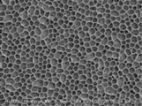
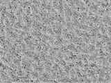
- FIG. 2 shows an SEM image obtained by observing the surface of the separator from the direction perpendicular to the plane.
- PVDF-HFP polyvinylidene fluoride-hexafluoropropylene copolymer
- KYNAR 2800 manufactured by Arkema Co.
- the concentration of PVDF-HFP with respect to the coating solution was 8% by mass.
- This coating solution is applied to both sides of a porous microporous polyethylene film (film thickness: 9.1 ⁇ m, Gurley value: 160 sec / 100 cc, porosity: 33%).
- a coating layer was formed.
- the contained resin was solidified.
- the composite membrane was washed with water and dried to obtain a separator having porous layers on both sides of the polyethylene microporous membrane. The surface of this separator was observed by SEM, and it was confirmed that the porous layer did not have a honeycomb structure.
- Example A4 A separator having a porous layer on both sides of a polyethylene microporous membrane was obtained in the same manner as in Example A1, except that PVDF-HFP was changed from KYNAR2800 manufactured by Arkema to Solef 21216 manufactured by Solvay. The surface of this separator was observed with an SEM, and it was confirmed that the porous layer had a honeycomb structure.
- Example B1> In a mixed solvent in which acetone and water are mixed at a mass ratio of 95: 5, polyvinylidene fluoride-hexafluoropropylene copolymer (PVDF-HFP, KYNAR2800 manufactured by Arkema) and sorbitan monopalmitate (HLB value) as a surfactant are used. 6.7) was dissolved to prepare a coating solution. The mass ratio of PVDF-HFP and sorbitan monopalmitate contained in the coating solution was 99.8: 0.2, and the total concentration of both in the coating solution was 10% by mass.
- PVDF-HFP polyvinylidene fluoride-hexafluoropropylene copolymer
- HLB value sorbitan monopalmitate
- This coating solution was coated on both sides of a porous microporous polyethylene film (film thickness: 9.1 ⁇ m, Gurley value: 160 sec / 100 cc, porosity: 33%) using a bar coater # 6.
- the coating layer was formed on both surfaces of the porous substrate.
- This coating layer was dried at 60 ° C. to obtain a separator having a porous layer on both sides of a polyethylene microporous membrane. The surface of this separator was observed with an SEM, and it was confirmed that the porous layer had a honeycomb structure and a fine porous structure.
- Example B2> A porous layer is provided on both sides of a polyethylene microporous membrane in the same manner as in Example B1, except that the mass ratio of PVDF-HFP and sorbitan monopalmitate contained in the coating solution was changed to 99.5: 0.5. A separator was obtained. The surface of this separator was observed with an SEM, and it was confirmed that the porous layer had a honeycomb structure and a fine porous structure.
- Example B3> A separator having a porous layer on both sides of a polyethylene microporous membrane was obtained in the same manner as in Example B1, except that the mass ratio of PVDF-HFP and sorbitan monopalmitate contained in the coating solution was changed to 99: 1. . The surface of this separator was observed with an SEM, and it was confirmed that the porous layer had a honeycomb structure and a fine porous structure.
- Example B4> A separator having a porous layer on both sides of a polyethylene microporous membrane was obtained in the same manner as in Example B1, except that the mass ratio of PVDF-HFP and sorbitan monopalmitate contained in the coating solution was changed to 98: 2. . The surface of this separator was observed with an SEM, and it was confirmed that the porous layer had a honeycomb structure and a fine porous structure.
- Example B5> In a mixed solvent in which acetone and water are mixed at a mass ratio of 95: 5, polyvinylidene fluoride-hexafluoropropylene copolymer (PVDF-HFP, KYNAR2800 manufactured by Arkema) and sorbitan monopalmitate (HLB value) as a surfactant are used. 6.7). The mass ratio of PVDF-HFP and sorbitan monopalmitate contained in this solution was 99: 1, and the total concentration of both in this solution was 10% by mass. Further, magnesium hydroxide (Kisuma Chemical Co., Ltd., Kisuma 5P) was dispersed as an inorganic filler in the above solution to prepare a coating solution.
- PVDF-HFP polyvinylidene fluoride-hexafluoropropylene copolymer
- HLB value sorbitan monopalmitate
- the mass ratio of PVDF-HFP and magnesium hydroxide contained in the coating solution was 80:20.
- This coating solution was coated on both sides of a porous microporous polyethylene film (film thickness: 9.1 ⁇ m, Gurley value: 160 sec / 100 cc, porosity: 33%) using a bar coater # 6.
- the coating layer was formed on both surfaces of the porous substrate.
- This coating layer was dried at 60 ° C. to obtain a separator having a porous layer on both sides of a polyethylene microporous membrane. The surface of this separator was observed with an SEM, and it was confirmed that the porous layer had a honeycomb structure and a fine porous structure.
- Example B6 A separator having a porous layer on both sides of a polyethylene microporous membrane was obtained in the same manner as in Example B5 except that the mass ratio of PVDF-HFP and magnesium hydroxide contained in the coating solution was changed to 60:40. The surface of this separator was observed with an SEM, and it was confirmed that the porous layer had a honeycomb structure and a fine porous structure.
- Example B7 As a surfactant, sorbitan monopalmitate (HLB value 6.7) and sorbitan trioleate (HLB value 1.8) were used at a mass ratio of 65.3: 34.7, and PVDF-HFP contained in the coating solution A separator having a porous layer on both sides of a polyethylene microporous membrane was obtained in the same manner as in Example B1, except that the surfactant mass ratio was changed to 99: 1. The surface of this separator was observed with an SEM, and it was confirmed that the porous layer had a honeycomb structure and a fine porous structure.
- Example B8> As a surfactant, sorbitan monopalmitate (HLB value 6.7) and Tween 80 (PEG-20 sorbitan monooleate, HLB value 15.0) were used at a mass ratio of 84.3: 15.7 and included in the coating liquid.
- a separator having a porous layer on both sides of a polyethylene microporous membrane was obtained in the same manner as in Example B1, except that the mass ratio of PVDF-HFP and surfactant was changed to 99: 1. The surface of this separator was observed with an SEM, and it was confirmed that the porous layer had a honeycomb structure and a fine porous structure.
- Example B9 The surfactant was changed from sorbitan monopalmitate (HLB value 6.7) to sorbitan monostearate (HLB value 4.7), and the mass ratio of PVDF-HFP and surfactant contained in the coating solution was 99: A separator having a porous layer on both sides of a polyethylene microporous membrane was obtained in the same manner as in Example B1, except that the number was changed to 1. The surface of this separator was observed with an SEM, and it was confirmed that the porous layer had a honeycomb structure and a fine porous structure.
- Example B10> A separator having a porous layer on both sides of a polyethylene microporous membrane was obtained in the same manner as in Example B1 except that the coating liquid did not contain sorbitan monopalmitate.
- This separator was immersed in a solution obtained by adding sorbitan monopalmitate (HLB value 6.7) as water as a surfactant to obtain a separator having a surfactant added to the porous layer.
- HLB value 6.7 sorbitan monopalmitate
- the polyvinylidene fluoride resin and the surfactant are not mixed, and the surfactant is interposed between the polyethylene microporous membrane and the porous layer. Not done.
- the surface of this separator was observed with an SEM, and it was confirmed that the porous layer had a honeycomb structure and a fine porous structure.
- Example B1 A separator having a porous layer on both sides of a polyethylene microporous membrane was obtained in the same manner as in Example B1, except that the mass ratio of PVDF-HFP and sorbitan monopalmitate contained in the coating solution was changed to 90:10. .
- the surface of this separator was observed with an SEM, and it was confirmed that the porous layer did not have a honeycomb structure and had a structure in which micropores were slightly formed.
- ⁇ Comparative Example B2> In a mixed solvent in which acetone, isopropanol, and water are mixed at a mass ratio of 89.4: 7.1: 3.5, a polyvinylidene fluoride-hexafluoropropylene copolymer (PVDF-HFP, KYNAR2800 manufactured by Arkema) and an interface Sorbitan monopalmitate (HLB value 6.7) was dissolved as an activator to prepare a coating solution.
- the mass ratio of PVDF-HFP and sorbitan monopalmitate contained in the coating solution was 99: 1, and the total concentration of both in the coating solution was 10% by mass.
- This coating solution was coated on both sides of a porous microporous polyethylene film (film thickness: 9.1 ⁇ m, Gurley value: 160 sec / 100 cc, porosity: 33%) using a bar coater # 6.
- the coating layer was formed on both surfaces of the porous substrate.
- This coating layer was dried at 60 ° C. to obtain a separator having a porous layer on both sides of a polyethylene microporous membrane.
- the surface of the separator was observed with an SEM, and it was confirmed that the porous layer did not have a honeycomb structure, and the porous structure had fine pores distributed with high uniformity.
- Example B3 A separator having a porous layer on both sides of a polyethylene microporous membrane was obtained in the same manner as in Example B5 except that the mass ratio of PVDF-HFP and magnesium hydroxide contained in the coating solution was changed to 40:60. The surface of the separator was observed with an SEM, and it was confirmed that the porous layer did not have a honeycomb structure, and the porous structure had fine pores distributed with high uniformity.
- ⁇ Battery manufacturing efficiency test> Two separators (width 108 mm) were prepared and overlapped, and one end in the MD direction was wound around a stainless steel core. A positive electrode (width: 106.5 mm) was sandwiched between two separators, a negative electrode (width: 107 mm) was placed on one separator, and this laminate was wound to produce 50 continuous wound electrode bodies. did. The amount of protrusion of the separator from the positive electrode is in the range of 1.5 mm ⁇ 0.3 mm, the amount of protrusion of the separator from the negative electrode is in the range of 1.0 mm ⁇ 0.3 mm, and the lamination of the two separators The case where the part did not slip
- the number ratio (%) of the passed winding electrode body was computed, and it classified as follows.
- ⁇ Battery performance test> [Production of negative electrode] 300 g of artificial graphite as negative electrode active material, 7.5 g of water-soluble dispersion containing 40% by mass of modified styrene-butadiene copolymer as binder, 3 g of carboxymethyl cellulose as thickener, and appropriate amount of water The mixture was stirred and mixed with a type mixer to prepare a negative electrode slurry. This negative electrode slurry was applied to a 10 ⁇ m thick copper foil as a negative electrode current collector, dried and pressed to obtain a negative electrode having a negative electrode active material layer.
- Electrode tabs were welded to the positive electrode and the negative electrode, respectively, and the positive electrode and the negative electrode were joined via a separator to produce a battery element.
- This battery element was accommodated in an aluminum pack, infiltrated with an electrolytic solution, and sealed using a vacuum sealer.
- As the electrolytic solution 1M LiPF 6 -ethylene carbonate: ethyl methyl carbonate (mass ratio 3: 7) was used. Thereafter, the aluminum pack containing the battery element and the electrolytic solution was subjected to hot pressing (load: 20 kg per 1 cm 2 of electrode, temperature: 90 ° C., pressing time: 2 minutes) with a hot press machine, and a secondary test was performed. A battery was obtained.
- Example A1 or Example B1 was set to 100, and the relative value of the other Example and the comparative example was computed.
- Tables 1 and 3 show various physical property values of the separators of Examples and Comparative Examples.
- the average diameter of the micropores existing on the surface of the porous layer is described instead of the average diameter of the cell opening.
- Tables 2 and 4 show the evaluation results of the secondary batteries prepared using the separators of the examples and comparative examples.
Landscapes
- Chemical & Material Sciences (AREA)
- Chemical Kinetics & Catalysis (AREA)
- Electrochemistry (AREA)
- General Chemical & Material Sciences (AREA)
- Engineering & Computer Science (AREA)
- Manufacturing & Machinery (AREA)
- Materials Engineering (AREA)
- Cell Separators (AREA)
Abstract
Description
本発明の実施形態は、優れたハンドリング性及び電解液との高い親和性をバランスよく実現した非水系二次電池用セパレータを提供することを目的とする。
さらに、本発明の実施形態は、製造効率高く非水系二次電池を提供することを目的とする。
[1] 熱可塑性樹脂を含む多孔質基材と、前記多孔質基材の片面又は両面に設けられた、ポリフッ化ビニリデン系樹脂を含む多孔質層であって、該多孔質層の面垂直方向に開口したセルが該多孔質層の面方向に隣接して多数並んだ構造を有し、水の接触角が115°~140°である多孔質層と、を備えた非水系二次電池用セパレータ。
[2] 前記セルの開口部の平均径が0.1μm~10μmである、[1]に記載の非水系二次電池用セパレータ。
[3] 前記多孔質層の空孔率が40%~80%である、[1]又は[2]に記載の非水系二次電池用セパレータ。
[4] 前記多孔質層上で測定した帯電減衰半減期が300秒以下である、[1]~[3]のいずれかに記載の非水系二次電池用セパレータ。
[5] 電解液に浸したときに動的濡れ張力が1.5mNになるまでの時間が10秒以下である、[1]~[4]のいずれかに記載の非水系二次電池用セパレータ。
[6] 前記多孔質層が、HLB値が5.0~8.0である界面活性剤をさらに含み、前記ポリフッ化ビニリデン系樹脂と前記界面活性剤とが前記多孔質層の内部において混在している、[1]~[5]のいずれかに記載の非水系二次電池用セパレータ。
[7] 前記多孔質層において、前記ポリフッ化ビニリデン系樹脂と前記界面活性剤との質量比が99.9:0.1~95.0:5.0である、[6]に記載の非水系二次電池用セパレータ。
[8] 前記多孔質基材と前記多孔質層との間の剥離強度が0.1N/cm~2.0N/cmである、[1]~[7]のいずれかに記載の非水系二次電池用セパレータ。
[9] 前記多孔質層がフィラーをさらに含む、[1]~[8]のいずれかに記載の非水系二次電池用セパレータ。
[10] 前記多孔質層を前記多孔質基材の両面に有する、[1]~[9]のいずれかに記載の非水系二次電池用セパレータ。
[11] 前記多孔質基材がポリエチレンを含むポリオレフィン微多孔膜である、[1]~[10]のいずれかに記載の非水系二次電池用セパレータ。
[12] 前記多孔質基材がポリエチレンとポリプロピレンとを含むポリオレフィン微多孔膜である、[1]~[11]のいずれかに記載の非水系二次電池用セパレータ。
[13] [6]~[12]のいずれかに記載の非水系二次電池用セパレータを製造する方法であって、ポリフッ化ビニリデン系樹脂とHLB値が5.0~8.0である界面活性剤とを溶媒に溶解させて得た溶液を多孔質基材の片面又は両面に塗工して塗工層を形成する工程と、前記塗工層から前記溶媒を除去して多孔質層を形成する工程と、を有する、非水系二次電池用セパレータの製造方法。
[14] 正極と、負極と、前記正極及び前記負極の間に配置された[1]~[12]のいずれかに記載の非水系二次電池用セパレータとを備え、リチウムのドープ・脱ドープにより起電力を得る非水系二次電池。
さらに、本発明の実施形態によれば、製造効率高く非水系二次電池が提供される。
本開示の非水系二次電池用セパレータ(単に「セパレータ」とも称する。)は、熱可塑性樹脂を含む多孔質基材と、前記多孔質基材の片面又は両面に設けられた、ポリフッ化ビニリデン系樹脂を含む多孔質層であって、該多孔質層の面垂直方向に開口したセルが該多孔質層の面方向に隣接して多数並んだ構造(以下「ハニカム構造」とも称する。)を有し、水の接触角が115°~140°である多孔質層と、を備える。本開示のセパレータにおいて、前記多孔質層は、セパレータの最外層として存在し、電極に接する層である。
本開示において多孔質基材とは、内部に空孔ないし空隙を有する基材を意味する。このような基材としては、微多孔膜;繊維状物からなる、不織布、紙等の多孔性シート;などが挙げられる。本開示においては、セパレータの薄膜化及び強度の観点で、微多孔膜が好ましい。微多孔膜とは、内部に多数の微細孔を有し、これら微細孔が連結された構造となっており、一方の面から他方の面へと気体あるいは液体が通過可能となった膜を意味する。
本開示において多孔質層は、ポリフッ化ビニリデン系樹脂を含み、多孔質基材の片面又は両面にセパレータの最外層として設けられた層であり、セパレータと電極とを重ねてプレス又は熱プレスしたときに電極と接着する層である。
本開示において、ポリフッ化ビニリデン系樹脂としては、フッ化ビニリデンの単独重合体(即ちポリフッ化ビニリデン);フッ化ビニリデンと他の共重合可能なモノマーとの共重合体(ポリフッ化ビニリデン共重合体);これらの混合物;が挙げられる。フッ化ビニリデンと共重合可能なモノマーとしては、例えば、テトラフロロエチレン、ヘキサフロロプロピレン、トリフロロエチレン、トリクロロエチレン、フッ化ビニル等が挙げられ、1種又は2種以上を用いることができる。ポリフッ化ビニリデン系樹脂は、構成単位としてフッ化ビニリデンを70mol%以上含有することが好ましく、電極との接合工程において十分な力学物性を確保するという観点で、フッ化ビニリデンを94mol%以上含有することが好ましい。
本開示において多孔質層は、ポリフッ化ビニリデン系樹脂以外のその他の樹脂を含んでもよい。その他の樹脂としては、フッ素系ゴム、アクリル系樹脂、スチレン-ブタジエン共重合体、ビニルニトリル化合物(アクリロニトリル、メタクリロニトリル等)の単独重合体又は共重合体、カルボキシメチルセルロース、ヒドロキシアルキルセルロース、ポリビニルアルコール、ポリビニルブチラール、ポリビニルピロリドン、ポリエーテル(ポリエチレンオキサイド、ポリプロピレンオキサイド等)などが挙げられる。
本開示においては、多孔質層は、セパレータの滑り性や耐熱性を向上させる目的で、無機物又は有機物からなるフィラーやその他添加物を含んでいてもよい。その場合、本開示の効果を阻害しない程度の含有量や粒子サイズとすることが好ましい。
本開示における無機フィラーとしては、電解液に対して安定であり、且つ、電気化学的に安定な無機フィラーが好ましい。具体的には例えば、水酸化アルミニウム、水酸化マグネシウム、水酸化カルシウム、水酸化クロム、水酸化ジルコニウム、水酸化セリウム、水酸化ニッケル、水酸化ホウ素等の金属水酸化物;シリカ、アルミナ、ジルコニア、酸化マグネシウム等の金属酸化物;炭酸カルシウム、炭酸マグネシウム等の炭酸塩;硫酸バリウム、硫酸カルシウム等の硫酸塩;ケイ酸カルシウム、タルク等の粘土鉱物;などが挙げられる。無機フィラーは、金属水酸化物及び金属酸化物の少なくとも一種を含むことが好ましく、難燃性付与や除電効果の観点から、金属水酸化物の少なくとも一種を含むことがより好ましく、水酸化マグネシウムを含むことが更に好ましい。これらの無機フィラーは、1種を単独で使用しても2種以上を組み合わせて使用してもよい。無機フィラーは、シランカップリング剤等により表面修飾されたものでもよい。
本開示における有機フィラーとしては、例えば、架橋ポリメタクリル酸メチル等の架橋アクリル系樹脂、架橋ポリスチレンなどが挙げられ、架橋ポリメタクリル酸メチルが好ましい。
本開示における多孔質層は、セパレータのイオン透過性が向上する観点で、HLB値が5.0~8.0である界面活性剤を含み、多孔質層の内部において該界面活性剤とポリフッ化ビニリデン系樹脂とが混在していることが好ましい。上記界面活性剤が多孔質層と多孔質基材との間の界面に存在し機能することにより、セパレータのイオン透過性が向上すると考えられる。
本開示のセパレータの膜厚は、電池のエネルギー密度及び出力特性の観点から、30μm以下が好ましく、25μm以下がより好ましい。
セパレータをMD方向45mm×TD方向45mmの大きさに3枚切り出して、これを試験片とする。試験片をドライルーム(露点-60℃)に1時間放置した後、静電気除去器で10秒間除電して、次いでシシド静電気株式会社製STATIC HONESTMETER TYPE H-0110を用いて、多孔質層上で帯電減衰半減期(秒)を測定する。試験片3枚についてそれぞれ帯電減衰半減期を測定し、測定値を平均する。
セパレータをMD方向25mm×TD方向25mmの大きさに3枚切り出して、これを試験片とする。ウィルヘルミィ法を適用した動的濡れ性試験機(株式会社レスカ製WET-6200)を用いて、室温にて試験片を電解液に浸漬し、動的濡れ張力が1.5mNになるまでの時間(秒)を測定する。電解液としては、1M LiBF4-エチレンカーボネート:メチルエチルカーボネート=3:7(質量比)を用いる。試験片3枚についてそれぞれ上記時間を測定し、測定値を平均する。
本開示のセパレータは、例えば、少なくともポリフッ化ビニリデン系樹脂を含む塗工液を多孔質基材上に塗工し塗工層を形成し、次いで塗工層に含まれるポリフッ化ビニリデン系樹脂を固化させることで、多孔質層を多孔質基材上に形成する方法で製造できる。ハニカム構造を有する多孔質層を形成する方法としては、具体的には、下記(i)~(iii)の方法が挙げられ、中でも下記(i)の方法が好ましい。
本開示の非水系二次電池は、リチウムのドープ・脱ドープにより起電力を得る非水系二次電池であり、正極と、負極と、本開示の非水系二次電池用セパレータとを備える。ドープとは、吸蔵、担持、吸着、又は挿入を意味し、正極等の電極の活物質にリチウムイオンが入る現象を意味する。
各実施例及び比較例で適用した測定方法は、以下のとおりである。
多孔質基材及びセパレータの膜厚(μm)は、接触式の厚み計(ミツトヨ社製LITEMATIC)を用いて20点を測定し、これを平均することで求めた。測定端子として直径5mmの円柱状の端子を用い、測定中に7gの荷重が印加されるように調整した。
多孔質層の塗工厚(μm)は、セパレータの膜厚から多孔質基材の膜厚を減算して求めた。
目付(1m2当たりの質量)は、セパレータを10cm×30cmに切り出してその質量を測定し、この質量を面積で除することで求めた。
多孔質層の塗工量(g/m2)は、セパレータの目付から多孔質基材の目付を減算して求めた。
多孔質基材及びセパレータのガーレ値(秒/100cc)は、JIS P8117(2009)に従い、ガーレ式デンソメータ(東洋精機社製G-B2C)を用いて測定した。
多孔質基材及び多孔質層の空孔率は、下記の算出方法に従って求めた。
構成材料がa、b、c、・・・、nであり、各構成材料の質量がWa、Wb、Wc、・・・、Wn(g/cm2)であり、各構成材料の真密度がda、db、dc、・・・、dn(g/cm3)であり、厚さをt(cm)としたとき、空孔率ε(%)は以下の式より求められる。
ε={1-(Wa/da+Wb/db+Wc/dc+・・・+Wn/dn)/t}×100
走査型電子顕微鏡(キーエンス社製3Dリアルサーフェスビュー顕微鏡VE-8800)を使用してセパレータの表面を観察した。得られた画像からセルを任意に20個選び、各セルの開口部の内縁それぞれについて最大径及び最小径を求めて{(最大径+最小径)/2)}を算出し、20個の平均値をセルの開口部の平均径とした。
協和界面科学社製の接触角計DropMaster DM-301を使用して、多孔質層表面の水の接触角を測定した。水として蒸留水を用い、シリンジを用いてセパレータの表面に1μLの水滴を形成し、接触角の測定を行った。10個の水滴について接触角の測定を行い、平均値を算出した。
セパレータをMD方向45mm×TD方向45mmの大きさに3枚切り出して、これを試験片とした。試験片をドライルーム(露点-60℃)に1時間放置した後、静電気除去器で10秒間除電して、次いでシシド静電気株式会社製STATIC HONESTMETER TYPE H-0110を用いて、帯電減衰半減期(秒)を測定した。試験片3枚の測定値を平均し、セパレータの帯電減衰半減期(秒)とした。
セパレータをMD方向25mm×TD方向25mmの大きさに3枚切り出し、これを試験片とした。動的濡れ性試験機(株式会社レスカ製WET-6200)を用いて、室温にて試験片を電解液(1M LiBF4-エチレンカーボネート:メチルエチルカーボネート=3:7(質量比))に浸漬し、動的濡れ張力が1.5mNになるまでの時間(秒)を測定した。試験片3枚の測定値を平均し、これをセパレータの濡れ性の指標とした。
セパレータの両面に3M社製のメンディングテープを長さ方向がセパレータのMD方向に一致するように張り付けた。両面にメンディングテープが張り付いたセパレータを10mm幅に3枚切り出し、これを試験片とした。試験片の長さ方向(即ちセパレータのMD方向)の一端から、メンディングテープを直下の多孔質層と共に少し剥がし、2つに分離した端部をテンシロン(オリエンテック社製RTC-1210A)に把持させてT字剥離試験を行った。T字剥離試験の引張速度は20mm/minとし、多孔質基材から多孔質層が剥離する際の荷重(N)を測定し、測定開始後10mmから40mmまでの荷重を0.4mm間隔で採取しその平均を算出し、さらに試験片3枚の測定値を平均して、セパレータの剥離強度(N/cm)とした。
アセトンと水とを質量比95:5で混合した混合溶媒に、ポリフッ化ビニリデン-ヘキサフルオロプロピレン共重合体(PVDF-HFP、アルケマ社製KYNAR2800)を溶解させ塗工液を作製した。塗工液に対するPVDF-HFPの濃度を10質量%とした。
この塗工液を、多孔質基材であるポリエチレン微多孔膜(膜厚9.1μm、ガーレ値160秒/100cc、空孔率33%)の両面にバーコータ#6を用いて塗工し、多孔質基材の両面に塗工層を形成した。この塗工層を60℃で乾燥し、ポリエチレン微多孔膜の両面に多孔質層を有するセパレータを得た。このセパレータの表面を走査型電子顕微鏡(SEM)で観察し、多孔質層がハニカム構造を有することを確認した。このセパレータの表面を面垂直方向から観察して得たSEM画像を図1に示す。
混合溶媒におけるアセトンと水の質量比を97.5:2.5に変更した以外は実施例A1と同様にして、ポリエチレン微多孔膜の両面に多孔質層を有するセパレータを得た。このセパレータの表面をSEMで観察し、多孔質層がハニカム構造を有することを確認した。
特開2004-356102号公報に記載されている実施例に基づいて、下記のとおり、セパレータを作製した。
アセトンとイソプロパノールと水とを質量比89.4:7.1:3.5で混合した混合溶媒に、ポリフッ化ビニリデン-ヘキサフルオロプロピレン共重合体(PVDF-HFP、アルケマ社製KYNAR2800)を溶解させ塗工液を作製した。塗工液に対するPVDF-HFPの濃度を2.6質量%とした。
この塗工液を、多孔質基材であるポリエチレン微多孔膜(膜厚9.1μm、ガーレ値160秒/100cc、空孔率33%)の両面にバーコータ#6を用いて塗工し、多孔質基材の両面に塗工層を形成した。この塗工層を60℃で乾燥し、ポリエチレン微多孔膜の両面に多孔質層を有するセパレータを得た。このセパレータの表面をSEMで観察し、多孔質層がハニカム構造を有しないことを確認した。このセパレータは多孔質層が剥がれやすく、多孔質層及びセパレータの各種物性値を測定することが困難であり、また、このセパレータを用いて電池を作製することができなかった。
塗工液におけるPVDF-HFPの濃度を10質量%に変更した以外は比較例A1と同様にして、ポリエチレン微多孔膜の両面に多孔質層を有するセパレータを得た。このセパレータの表面をSEMで観察し、多孔質層がハニカム構造を有しないことを確認した。このセパレータの表面を面垂直方向から観察して得たSEM画像を図2に示す。
ジメチルアセトアミドとトリプロピレングリコールとを質量比8:2で混合した混合溶媒に、ポリフッ化ビニリデン-ヘキサフルオロプロピレン共重合体(PVDF-HFP、アルケマ社製KYNAR2800)を溶解させ塗工液を作製した。塗工液に対するPVDF-HFPの濃度を8質量%とした。
この塗工液を、多孔質基材であるポリエチレン微多孔膜(膜厚9.1μm、ガーレ値160秒/100cc、空孔率33%)の両面に塗工し、多孔質基材の両面に塗工層を形成した。多孔質基材の両面に塗工層を有する複合膜を凝固液(水:ジメチルアセトアミド:トリプロピレングリコール=57:30:13[質量比]、液温40℃)に浸漬し、塗工層に含まれる樹脂を固化させた。次いで、複合膜を水洗し乾燥して、ポリエチレン微多孔膜の両面に多孔質層を有するセパレータを得た。このセパレータの表面をSEMで観察し、多孔質層がハニカム構造を有しないことを確認した。
PVDF-HFPをアルケマ社製KYNAR2800からSolvay社製Solef21216に変更した以外は実施例A1と同様にして、ポリエチレン微多孔膜の両面に多孔質層を有するセパレータを得た。このセパレータの表面をSEMで観察し、多孔質層がハニカム構造を有することを確認した。
アセトンと水とを質量比95:5で混合した混合溶媒に、ポリフッ化ビニリデン-ヘキサフルオロプロピレン共重合体(PVDF-HFP、アルケマ社製KYNAR2800)と、界面活性剤としてソルビタンモノパルミテート(HLB値6.7)とを溶解させ塗工液を作製した。塗工液に含まれるPVDF-HFPとソルビタンモノパルミテートの質量比を99.8:0.2とし、塗工液に対する両者の合計濃度を10質量%とした。
この塗工液を、多孔質基材であるポリエチレン微多孔膜(膜厚9.1μm、ガーレ値160秒/100cc、空孔率33%)の両面にバーコータ#6を用いて塗工し、多孔質基材の両面に塗工層を形成した。この塗工層を60℃で乾燥し、ポリエチレン微多孔膜の両面に多孔質層を有するセパレータを得た。このセパレータの表面をSEMで観察し、多孔質層がハニカム構造及び微小な多孔構造を有することを確認した。
塗工液に含まれるPVDF-HFPとソルビタンモノパルミテートの質量比を99.5:0.5に変更した以外は実施例B1と同様にして、ポリエチレン微多孔膜の両面に多孔質層を有するセパレータを得た。このセパレータの表面をSEMで観察し、多孔質層がハニカム構造及び微小な多孔構造を有することを確認した。
塗工液に含まれるPVDF-HFPとソルビタンモノパルミテートの質量比を99:1に変更した以外は実施例B1と同様にして、ポリエチレン微多孔膜の両面に多孔質層を有するセパレータを得た。このセパレータの表面をSEMで観察し、多孔質層がハニカム構造及び微小な多孔構造を有することを確認した。
塗工液に含まれるPVDF-HFPとソルビタンモノパルミテートの質量比を98:2に変更した以外は実施例B1と同様にして、ポリエチレン微多孔膜の両面に多孔質層を有するセパレータを得た。このセパレータの表面をSEMで観察し、多孔質層がハニカム構造及び微小な多孔構造を有することを確認した。
アセトンと水とを質量比95:5で混合した混合溶媒に、ポリフッ化ビニリデン-ヘキサフルオロプロピレン共重合体(PVDF-HFP、アルケマ社製KYNAR2800)と、界面活性剤としてソルビタンモノパルミテート(HLB値6.7)とを溶解させた。この溶液に含まれるPVDF-HFPとソルビタンモノパルミテートの質量比を99:1とし、この溶液に対する両者の合計濃度を10質量%とした。
さらに上記の溶液に、無機フィラーとして水酸化マグネシウム(協和化学社製キスマ5P)を分散させ塗工液を作製した。塗工液に含まれるPVDF-HFPと水酸化マグネシウムの質量比を80:20とした。
この塗工液を、多孔質基材であるポリエチレン微多孔膜(膜厚9.1μm、ガーレ値160秒/100cc、空孔率33%)の両面にバーコータ#6を用いて塗工し、多孔質基材の両面に塗工層を形成した。この塗工層を60℃で乾燥し、ポリエチレン微多孔膜の両面に多孔質層を有するセパレータを得た。このセパレータの表面をSEMで観察し、多孔質層がハニカム構造及び微小な多孔構造を有することを確認した。
塗工液に含まれるPVDF-HFPと水酸化マグネシウムの質量比を60:40に変更した以外は実施例B5と同様にして、ポリエチレン微多孔膜の両面に多孔質層を有するセパレータを得た。このセパレータの表面をSEMで観察し、多孔質層がハニカム構造及び微小な多孔構造を有することを確認した。
界面活性剤としてソルビタンモノパルミテート(HLB値6.7)とソルビタントリオレート(HLB値1.8)とを質量比65.3:34.7で用い、塗工液に含まれるPVDF-HFPと界面活性剤の質量比を99:1に変更した以外は実施例B1と同様にして、ポリエチレン微多孔膜の両面に多孔質層を有するセパレータを得た。このセパレータの表面をSEMで観察し、多孔質層がハニカム構造及び微小な多孔構造を有することを確認した。
界面活性剤としてソルビタンモノパルミテート(HLB値6.7)とTween80(PEG-20ソルビタンモノオレート、HLB値15.0)とを質量比84.3:15.7で用い、塗工液に含まれるPVDF-HFPと界面活性剤の質量比を99:1に変更した以外は実施例B1と同様にして、ポリエチレン微多孔膜の両面に多孔質層を有するセパレータを得た。このセパレータの表面をSEMで観察し、多孔質層がハニカム構造及び微小な多孔構造を有することを確認した。
界面活性剤をソルビタンモノパルミテート(HLB値6.7)からソルビタンモノステアレート(HLB値4.7)に変更し、塗工液に含まれるPVDF-HFPと界面活性剤の質量比を99:1に変更した以外は実施例B1と同様にして、ポリエチレン微多孔膜の両面に多孔質層を有するセパレータを得た。このセパレータの表面をSEMで観察し、多孔質層がハニカム構造及び微小な多孔構造を有することを確認した。
塗工液にソルビタンモノパルミテートを含まない以外は実施例B1と同様にして、ポリエチレン微多孔膜の両面に多孔質層を有するセパレータを得た。このセパレータを、界面活性剤としてソルビタンモノパルミテート(HLB値6.7)を水に添加した液に浸漬し、多孔質層に界面活性剤を付与したセパレータを得た。このセパレータの多孔質層の内部においては、ポリフッ化ビニリデン系樹脂と上記界面活性剤とが混在した状態になっておらず、上記界面活性剤はポリエチレン微多孔膜と多孔質層との間に介在していない。このセパレータの表面をSEMで観察し、多孔質層がハニカム構造及び微小な多孔構造を有することを確認した。
塗工液に含まれるPVDF-HFPとソルビタンモノパルミテートの質量比を90:10に変更した以外は実施例B1と同様にして、ポリエチレン微多孔膜の両面に多孔質層を有するセパレータを得た。このセパレータの表面をSEMで観察し、多孔質層がハニカム構造を有さず、微細孔がわずかに形成された構造であることを確認した。
アセトンとイソプロパノールと水とを質量比89.4:7.1:3.5で混合した混合溶媒に、ポリフッ化ビニリデン-ヘキサフルオロプロピレン共重合体(PVDF-HFP、アルケマ社製KYNAR2800)と、界面活性剤としてソルビタンモノパルミテート(HLB値6.7)とを溶解させ塗工液を作製した。塗工液に含まれるPVDF-HFPとソルビタンモノパルミテートの質量比を99:1とし、塗工液に対する両者の合計濃度を10質量%とした。
この塗工液を、多孔質基材であるポリエチレン微多孔膜(膜厚9.1μm、ガーレ値160秒/100cc、空孔率33%)の両面にバーコータ#6を用いて塗工し、多孔質基材の両面に塗工層を形成した。この塗工層を60℃で乾燥し、ポリエチレン微多孔膜の両面に多孔質層を有するセパレータを得た。このセパレータの表面をSEMで観察し、多孔質層がハニカム構造を有していないこと、微細孔が均一性高く分布した多孔構造であることを確認した。
塗工液に含まれるPVDF-HFPと水酸化マグネシウムの質量比を40:60に変更した以外は実施例B5と同様にして、ポリエチレン微多孔膜の両面に多孔質層を有するセパレータを得た。このセパレータの表面をSEMで観察し、多孔質層がハニカム構造を有していないこと、微細孔が均一性高く分布した多孔構造であることを確認した。
セパレータ(幅108mm)を2枚用意して重ね、MD方向の一端をステンレス製の巻芯に巻きつけた。2枚のセパレータの間に正極(幅106.5mm)をはさみ、一方のセパレータ上に負極(幅107mm)を配置し、この積層体を巻回して、巻回電極体を連続的に50個作製した。正極からのセパレータのはみ出し量が1.5mm±0.3mmの範囲内であり、負極からのセパレータのはみ出し量が1.0mm±0.3mmの範囲内であり、且つ、2枚のセパレータの積層部分がずれていない場合を合格と判断した。一方、上記に該当しない場合は不合格と判断した。そして、合格した巻回電極体の個数割合(%)を算出し、下記のとおり分類した。
A:合格した個数割合が100%
B:合格した個数割合が90%以上100%未満
C:合格した個数割合が90%未満
[負極の作製]
負極活物質である人造黒鉛300g、バインダであるスチレン-ブタジエン共重合体の変性体を40質量%含む水溶性分散液7.5g、増粘剤であるカルボキシメチルセルロース3g、及び適量の水を双腕式混合機にて攪拌して混合し、負極用スラリーを作製した。この負極用スラリーを負極集電体である厚さ10μmの銅箔に塗布し、乾燥後プレスして、負極活物質層を有する負極を得た。
正極活物質であるコバルト酸リチウム粉末89.5g、導電助剤であるアセチレンブラック4.5g、及びバインダであるポリフッ化ビニリデン6gを、ポリフッ化ビニリデンの濃度が6質量%となるようにN-メチル-ピロリドンに溶解し、双腕式混合機にて攪拌し、正極用スラリーを作製した。この正極用スラリーを正極集電体である厚さ20μmのアルミ箔に塗布し、乾燥後プレスして、正極活物質層を有する正極を得た。
正極と負極にそれぞれリードタブを溶接し、この正極と負極をセパレータを介して接合させ電池素子を作製した。この電池素子をアルミパック中に収容し電解液を浸み込ませ、真空シーラーを用いて封入した。電解液としては、1M LiPF6-エチレンカーボネート:エチルメチルカーボネート(質量比3:7)を用いた。その後、電池素子および電解液を収容したアルミパックに対して、熱プレス機により熱プレス(荷重:電極1cm2当たり20kg、温度:90℃、プレス時間:2分間)を行い、試験用の二次電池を得た。
試験用二次電池に対して100サイクルの充放電を行い、100サイクル後の容量維持率(%)を求めて、これをサイクル特性の指標とした。この試験において、充電は0.5C又は1.0C且つ4.2Vの定電流定電圧充電とし、放電は0.5C又は1.0C且つ2.75Vカットオフの定電流放電とした。実施例A1等においては、充放電の電流を0.5Cとし、実施例B1等においては、充放電の電流を1.0Cとした。
サイクル特性試験後の試験用二次電池を解体し、セパレータと電極との接着性を、接着力及び均一性の観点から確認した。
アルミパックから電池素子を取り出し、2つに切り分け、試験片を2個得た。1個の試験片で正極の180度剥離試験を行い、もう1個の試験片で負極の180度剥離試験を行った。180度剥離試験は、テンシロン(オリエンテック社製RTC-1210A)を用いて引張速度20mm/minの条件で行った。試験片から正極又は負極が剥離する際の荷重(N)を測定し、測定開始後10mmから40mmまでの荷重を0.4mm間隔で採取しその平均値を算出した。そして、正極及び負極のそれぞれについて、実施例A1又は実施例B1の平均値を100として、その他の実施例及び比較例の相対値を算出した。
180度剥離試験を終えた後の正極および負極について、セパレータと接していた側の表面を目視で観察し、下記のとおり分類した。
G1:セパレータの多孔質層がほぼ全て電極表面に付着していた。均一性は良好である。
G2:セパレータの多孔質層の大部分が電極表面に付着しているが、一部破損している。
NG:セパレータの多孔質層の大部分が180度剥離試験の際に著しく破損し、ほとんど電極表面に付着していない。均一性は不良である。
表2及び表4に、各実施例及び各比較例のセパレータを用いて作製した二次電池の評価結果を示す。


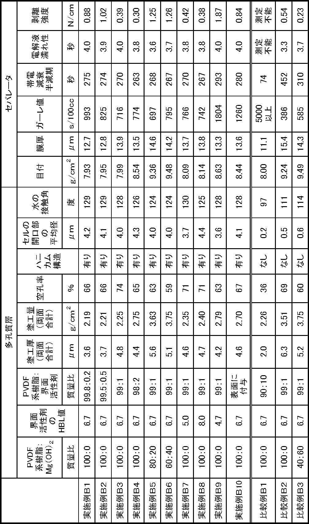

Claims (14)
- 熱可塑性樹脂を含む多孔質基材と、
前記多孔質基材の片面又は両面に設けられた、ポリフッ化ビニリデン系樹脂を含む多孔質層であって、該多孔質層の面垂直方向に開口したセルが該多孔質層の面方向に隣接して多数並んだ構造を有し、水の接触角が115°~140°である多孔質層と、
を備えた非水系二次電池用セパレータ。 - 前記セルの開口部の平均径が0.1μm~10μmである、請求項1に記載の非水系二次電池用セパレータ。
- 前記多孔質層の空孔率が40%~80%である、請求項1又は請求項2に記載の非水系二次電池用セパレータ。
- 前記多孔質層上で測定した帯電減衰半減期が300秒以下である、請求項1~請求項3のいずれか1項に記載の非水系二次電池用セパレータ。
- 電解液に浸したときに動的濡れ張力が1.5mNになるまでの時間が10秒以下である、請求項1~請求項4のいずれか1項に記載の非水系二次電池用セパレータ。
- 前記多孔質層が、HLB値が5.0~8.0である界面活性剤をさらに含み、
前記ポリフッ化ビニリデン系樹脂と前記界面活性剤とが前記多孔質層の内部において混在している、請求項1~請求項5のいずれか1項に記載の非水系二次電池用セパレータ。 - 前記多孔質層において、前記ポリフッ化ビニリデン系樹脂と前記界面活性剤との質量比が99.9:0.1~95.0:5.0である、請求項6に記載の非水系二次電池用セパレータ。
- 前記多孔質基材と前記多孔質層との間の剥離強度が0.1N/cm~2.0N/cmである、請求項1~請求項7のいずれか1項に記載の非水系二次電池用セパレータ。
- 前記多孔質層がフィラーをさらに含む、請求項1~請求項8のいずれか1項に記載の非水系二次電池用セパレータ。
- 前記多孔質層を前記多孔質基材の両面に有する、請求項1~請求項9のいずれか1項に記載の非水系二次電池用セパレータ。
- 前記多孔質基材がポリエチレンを含むポリオレフィン微多孔膜である、請求項1~請求項10のいずれか1項に記載の非水系二次電池用セパレータ。
- 前記多孔質基材がポリエチレンとポリプロピレンとを含むポリオレフィン微多孔膜である、請求項1~請求項11のいずれか1項に記載の非水系二次電池用セパレータ。
- 請求項6~請求項12のいずれか1項に記載の非水系二次電池用セパレータを製造する方法であって、
ポリフッ化ビニリデン系樹脂とHLB値が5.0~8.0である界面活性剤とを溶媒に溶解させて得た溶液を多孔質基材の片面又は両面に塗工して塗工層を形成する工程と、
前記塗工層から前記溶媒を除去して多孔質層を形成する工程と、
を有する、非水系二次電池用セパレータの製造方法。 - 正極と、負極と、前記正極及び前記負極の間に配置された請求項1~請求項12のいずれか1項に記載の非水系二次電池用セパレータとを備え、リチウムのドープ・脱ドープにより起電力を得る非水系二次電池。
Priority Applications (3)
| Application Number | Priority Date | Filing Date | Title |
|---|---|---|---|
| JP2015543202A JP5882549B1 (ja) | 2014-05-20 | 2015-05-18 | 非水系二次電池用セパレータ、その製造方法及び非水系二次電池 |
| CN201580021963.2A CN106233500A (zh) | 2014-05-20 | 2015-05-18 | 非水系二次电池用隔膜、其制造方法及非水系二次电池 |
| KR1020167030061A KR20170009838A (ko) | 2014-05-20 | 2015-05-18 | 비수계 이차전지용 세퍼레이터, 그 제조 방법 및 비수계 이차전지 |
Applications Claiming Priority (4)
| Application Number | Priority Date | Filing Date | Title |
|---|---|---|---|
| JP2014104352 | 2014-05-20 | ||
| JP2014-104352 | 2014-05-20 | ||
| JP2014168462 | 2014-08-21 | ||
| JP2014-168462 | 2014-08-21 |
Publications (1)
| Publication Number | Publication Date |
|---|---|
| WO2015178351A1 true WO2015178351A1 (ja) | 2015-11-26 |
Family
ID=54554020
Family Applications (1)
| Application Number | Title | Priority Date | Filing Date |
|---|---|---|---|
| PCT/JP2015/064224 Ceased WO2015178351A1 (ja) | 2014-05-20 | 2015-05-18 | 非水系二次電池用セパレータ、その製造方法及び非水系二次電池 |
Country Status (4)
| Country | Link |
|---|---|
| JP (1) | JP5882549B1 (ja) |
| KR (1) | KR20170009838A (ja) |
| CN (1) | CN106233500A (ja) |
| WO (1) | WO2015178351A1 (ja) |
Cited By (8)
| Publication number | Priority date | Publication date | Assignee | Title |
|---|---|---|---|---|
| JP2018002913A (ja) * | 2016-07-04 | 2018-01-11 | 株式会社ハッピージャパン | β型ポリフッ化ビニリデン膜付基材及びその製造方法、並びにβ型ポリフッ化ビニリデン膜を具備する圧電センサ及びその製造方法 |
| JP2018181648A (ja) * | 2017-04-14 | 2018-11-15 | 住友化学株式会社 | 非水電解液二次電池用絶縁性多孔質層 |
| JP2020077497A (ja) * | 2018-11-06 | 2020-05-21 | 旭化成株式会社 | 微細パタンを有するセパレータ、捲回体および非水電解質電池 |
| US20210074984A1 (en) * | 2018-11-02 | 2021-03-11 | Lg Chem, Ltd. | Crosslinked polyolefin separator having inorganic coating layer and high power secondary battery comprising the same |
| WO2023053771A1 (ja) * | 2021-09-30 | 2023-04-06 | パナソニックIpマネジメント株式会社 | リチウムイオン二次電池 |
| JP2023522386A (ja) * | 2020-12-29 | 2023-05-30 | エルジー エナジー ソリューション リミテッド | 電気化学素子用分離膜の製造方法、及びその製造方法によって製造された電気化学素子用分離膜 |
| JP2023536060A (ja) * | 2021-06-25 | 2023-08-23 | エルジー エナジー ソリューション リミテッド | 二次電池用分離膜 |
| WO2024167005A1 (ja) * | 2023-02-10 | 2024-08-15 | エリーパワー株式会社 | 非水電解質二次電池用セパレータ及び非水電解質二次電池 |
Families Citing this family (4)
| Publication number | Priority date | Publication date | Assignee | Title |
|---|---|---|---|---|
| JP6672208B2 (ja) | 2017-03-17 | 2020-03-25 | 株式会社東芝 | 二次電池、電池パック及び車両 |
| CN106953058A (zh) * | 2017-04-10 | 2017-07-14 | 天津中科先进技术研究院有限公司 | 锂离子电池隔膜 |
| CN108963156A (zh) * | 2018-07-10 | 2018-12-07 | 福建师范大学 | 铝酸酯偶联剂对涂覆膜的改性方法 |
| CN114024095B (zh) * | 2021-10-27 | 2022-08-05 | 长园泽晖新能源材料研究院(珠海)有限公司 | 一种具有特殊孔结构的涂层隔膜及其制备方法 |
Citations (9)
| Publication number | Priority date | Publication date | Assignee | Title |
|---|---|---|---|---|
| JP2006073221A (ja) * | 2004-08-31 | 2006-03-16 | Teijin Ltd | リチウムイオン二次電池用セパレータ及びリチウムイオン二次電池 |
| JP2009070609A (ja) * | 2007-09-11 | 2009-04-02 | Sony Corp | セパレータおよびこれを用いた電池 |
| JP2010092881A (ja) * | 2008-08-19 | 2010-04-22 | Teijin Ltd | 非水系二次電池用セパレータ |
| JP2010195899A (ja) * | 2009-02-24 | 2010-09-09 | Sumitomo Chemical Co Ltd | 多孔質フィルムの製造方法、多孔質フィルム、積層多孔質フィルムの製造方法、積層多孔質フィルムおよび電池用セパレータ |
| JP2011023162A (ja) * | 2009-07-14 | 2011-02-03 | Teijin Ltd | 非水系二次電池用セパレータ |
| JP2012104291A (ja) * | 2010-11-08 | 2012-05-31 | Sony Corp | 耐収縮性微多孔膜および電池用セパレータ |
| JP2012227066A (ja) * | 2011-04-21 | 2012-11-15 | Sony Corp | セパレータおよび非水電解質電池、ならびに電池パック、電子機器、電動車両、蓄電装置および電力システム |
| JP2013054972A (ja) * | 2011-09-05 | 2013-03-21 | Sony Corp | セパレータ、非水電解質電池、電池パック、電子機器、電動車両、蓄電装置および電力システム |
| JP2013137984A (ja) * | 2011-09-05 | 2013-07-11 | Sony Corp | セパレータおよび非水電解質電池 |
Family Cites Families (5)
| Publication number | Priority date | Publication date | Assignee | Title |
|---|---|---|---|---|
| US20040241550A1 (en) | 2003-05-28 | 2004-12-02 | Wensley C. Glen | Battery separator for lithium polymer battery |
| KR101110264B1 (ko) | 2003-11-19 | 2012-03-13 | 도레이 도넨 기노마쿠 고도가이샤 | 복합 미다공막 및 그 제조 방법과 용도 |
| JP2008297349A (ja) * | 2007-05-29 | 2008-12-11 | Nitto Denko Corp | 多孔質フィルムの製造方法 |
| TWI501451B (zh) | 2011-04-08 | 2015-09-21 | 帝人股份有限公司 | Non-aqueous secondary battery separator and non-aqueous secondary battery |
| CN103746085B (zh) * | 2013-11-07 | 2017-01-04 | 深圳市星源材质科技股份有限公司 | 一种涂层复合隔膜及其制备方法 |
-
2015
- 2015-05-18 KR KR1020167030061A patent/KR20170009838A/ko not_active Withdrawn
- 2015-05-18 CN CN201580021963.2A patent/CN106233500A/zh active Pending
- 2015-05-18 JP JP2015543202A patent/JP5882549B1/ja not_active Expired - Fee Related
- 2015-05-18 WO PCT/JP2015/064224 patent/WO2015178351A1/ja not_active Ceased
Patent Citations (9)
| Publication number | Priority date | Publication date | Assignee | Title |
|---|---|---|---|---|
| JP2006073221A (ja) * | 2004-08-31 | 2006-03-16 | Teijin Ltd | リチウムイオン二次電池用セパレータ及びリチウムイオン二次電池 |
| JP2009070609A (ja) * | 2007-09-11 | 2009-04-02 | Sony Corp | セパレータおよびこれを用いた電池 |
| JP2010092881A (ja) * | 2008-08-19 | 2010-04-22 | Teijin Ltd | 非水系二次電池用セパレータ |
| JP2010195899A (ja) * | 2009-02-24 | 2010-09-09 | Sumitomo Chemical Co Ltd | 多孔質フィルムの製造方法、多孔質フィルム、積層多孔質フィルムの製造方法、積層多孔質フィルムおよび電池用セパレータ |
| JP2011023162A (ja) * | 2009-07-14 | 2011-02-03 | Teijin Ltd | 非水系二次電池用セパレータ |
| JP2012104291A (ja) * | 2010-11-08 | 2012-05-31 | Sony Corp | 耐収縮性微多孔膜および電池用セパレータ |
| JP2012227066A (ja) * | 2011-04-21 | 2012-11-15 | Sony Corp | セパレータおよび非水電解質電池、ならびに電池パック、電子機器、電動車両、蓄電装置および電力システム |
| JP2013054972A (ja) * | 2011-09-05 | 2013-03-21 | Sony Corp | セパレータ、非水電解質電池、電池パック、電子機器、電動車両、蓄電装置および電力システム |
| JP2013137984A (ja) * | 2011-09-05 | 2013-07-11 | Sony Corp | セパレータおよび非水電解質電池 |
Cited By (14)
| Publication number | Priority date | Publication date | Assignee | Title |
|---|---|---|---|---|
| JP2018002913A (ja) * | 2016-07-04 | 2018-01-11 | 株式会社ハッピージャパン | β型ポリフッ化ビニリデン膜付基材及びその製造方法、並びにβ型ポリフッ化ビニリデン膜を具備する圧電センサ及びその製造方法 |
| JP2018181648A (ja) * | 2017-04-14 | 2018-11-15 | 住友化学株式会社 | 非水電解液二次電池用絶縁性多孔質層 |
| US11804635B2 (en) * | 2018-11-02 | 2023-10-31 | Lg Energy Solution, Ltd. | Crosslinked polyolefin separator having inorganic coating layer and high power secondary battery comprising the same |
| US20210074984A1 (en) * | 2018-11-02 | 2021-03-11 | Lg Chem, Ltd. | Crosslinked polyolefin separator having inorganic coating layer and high power secondary battery comprising the same |
| JP7213658B2 (ja) | 2018-11-06 | 2023-01-27 | 旭化成株式会社 | 微細パタンを有するセパレータ、捲回体および非水電解質電池 |
| JP2020077497A (ja) * | 2018-11-06 | 2020-05-21 | 旭化成株式会社 | 微細パタンを有するセパレータ、捲回体および非水電解質電池 |
| JP2023522386A (ja) * | 2020-12-29 | 2023-05-30 | エルジー エナジー ソリューション リミテッド | 電気化学素子用分離膜の製造方法、及びその製造方法によって製造された電気化学素子用分離膜 |
| JP7466690B2 (ja) | 2020-12-29 | 2024-04-12 | エルジー エナジー ソリューション リミテッド | 電気化学素子用分離膜の製造方法、及びその製造方法によって製造された電気化学素子用分離膜 |
| JP2023536060A (ja) * | 2021-06-25 | 2023-08-23 | エルジー エナジー ソリューション リミテッド | 二次電池用分離膜 |
| JP7729686B2 (ja) | 2021-06-25 | 2025-08-26 | エルジー エナジー ソリューション リミテッド | 二次電池用分離膜 |
| US12614816B2 (en) | 2021-06-25 | 2026-04-28 | Lg Energy Solution, Ltd. | Separator for secondary batteries |
| WO2023053771A1 (ja) * | 2021-09-30 | 2023-04-06 | パナソニックIpマネジメント株式会社 | リチウムイオン二次電池 |
| JPWO2023053771A1 (ja) * | 2021-09-30 | 2023-04-06 | ||
| WO2024167005A1 (ja) * | 2023-02-10 | 2024-08-15 | エリーパワー株式会社 | 非水電解質二次電池用セパレータ及び非水電解質二次電池 |
Also Published As
| Publication number | Publication date |
|---|---|
| JP5882549B1 (ja) | 2016-03-09 |
| JPWO2015178351A1 (ja) | 2017-04-20 |
| KR20170009838A (ko) | 2017-01-25 |
| CN106233500A (zh) | 2016-12-14 |
Similar Documents
| Publication | Publication Date | Title |
|---|---|---|
| JP5882549B1 (ja) | 非水系二次電池用セパレータ、その製造方法及び非水系二次電池 | |
| KR102818247B1 (ko) | 비수계 이차전지용 세퍼레이터 및 비수계 이차전지 | |
| US9887406B2 (en) | Separator for non-aqueous secondary battery, method for manufacturing the same, and non-aqueous secondary battery | |
| JP6143992B1 (ja) | 非水系二次電池用セパレータ及び非水系二次電池 | |
| JP4988973B1 (ja) | 非水系二次電池用セパレータおよび非水系二次電池 | |
| JP6205525B1 (ja) | 非水系二次電池用セパレータ及び非水系二次電池 | |
| JP6171117B1 (ja) | 非水系二次電池用セパレータ及び非水系二次電池 | |
| JP5213158B2 (ja) | 多層多孔質膜の製造方法、リチウムイオン電池用セパレータおよびリチウムイオン電池 | |
| JP6738339B2 (ja) | 電気化学素子用セパレータ、その製造方法および電気化学素子の製造方法 | |
| CN102959765B (zh) | 电池用隔膜以及电池 | |
| US20180166672A1 (en) | Separator for non-aqueous secondary battery and non-aqueous secondary battery | |
| JP5952509B2 (ja) | 非水系二次電池用セパレータ及び非水系二次電池 | |
| JP5745174B2 (ja) | 非水系二次電池用セパレータおよび非水系二次電池 | |
| KR20230107896A (ko) | 비수 전해질 전지용 세퍼레이터, 비수 전해질 전지,및 비수 전해질 전지의 제조 방법 | |
| JP5612797B1 (ja) | 非水系二次電池用セパレータおよび非水系二次電池 | |
| KR20160101895A (ko) | 비수계 이차전지용 세퍼레이터 및 비수계 이차전지 | |
| WO2011129169A1 (ja) | 電気化学素子用セパレータおよびそれを用いた電気化学素子、並びにその電気化学素子用セパレータの製造方法 | |
| JP6078703B1 (ja) | 非水系二次電池用セパレータ、非水系二次電池及び非水系二次電池の製造方法 | |
| KR20140071951A (ko) | 내열성 다공질막, 비수전지용 세퍼레이터 및 비수전지 | |
| JP2016181439A (ja) | 非水系二次電池用セパレータ及び非水系二次電池 | |
| KR20120086038A (ko) | 이차전지용 전극조립체 | |
| US20250174832A1 (en) | Separator for non-aqueous secondary battery, and non-aqueous secondary battery | |
| KR20240157706A (ko) | 비수계 이차전지용 세퍼레이터 및 비수계 이차전지 |
Legal Events
| Date | Code | Title | Description |
|---|---|---|---|
| ENP | Entry into the national phase |
Ref document number: 2015543202 Country of ref document: JP Kind code of ref document: A |
|
| 121 | Ep: the epo has been informed by wipo that ep was designated in this application |
Ref document number: 15795902 Country of ref document: EP Kind code of ref document: A1 |
|
| ENP | Entry into the national phase |
Ref document number: 20167030061 Country of ref document: KR Kind code of ref document: A |
|
| NENP | Non-entry into the national phase |
Ref country code: DE |
|
| 122 | Ep: pct application non-entry in european phase |
Ref document number: 15795902 Country of ref document: EP Kind code of ref document: A1 |