WO2015170499A1 - 薄膜形成装置 - Google Patents
薄膜形成装置 Download PDFInfo
- Publication number
- WO2015170499A1 WO2015170499A1 PCT/JP2015/054985 JP2015054985W WO2015170499A1 WO 2015170499 A1 WO2015170499 A1 WO 2015170499A1 JP 2015054985 W JP2015054985 W JP 2015054985W WO 2015170499 A1 WO2015170499 A1 WO 2015170499A1
- Authority
- WO
- WIPO (PCT)
- Prior art keywords
- main roll
- film forming
- forming chamber
- film
- thin film
- Prior art date
- Legal status (The legal status is an assumption and is not a legal conclusion. Google has not performed a legal analysis and makes no representation as to the accuracy of the status listed.)
- Ceased
Links
Images




Classifications
-
- C—CHEMISTRY; METALLURGY
- C23—COATING METALLIC MATERIAL; COATING MATERIAL WITH METALLIC MATERIAL; CHEMICAL SURFACE TREATMENT; DIFFUSION TREATMENT OF METALLIC MATERIAL; COATING BY VACUUM EVAPORATION, BY SPUTTERING, BY ION IMPLANTATION OR BY CHEMICAL VAPOUR DEPOSITION, IN GENERAL; INHIBITING CORROSION OF METALLIC MATERIAL OR INCRUSTATION IN GENERAL
- C23C—COATING METALLIC MATERIAL; COATING MATERIAL WITH METALLIC MATERIAL; SURFACE TREATMENT OF METALLIC MATERIAL BY DIFFUSION INTO THE SURFACE, BY CHEMICAL CONVERSION OR SUBSTITUTION; COATING BY VACUUM EVAPORATION, BY SPUTTERING, BY ION IMPLANTATION OR BY CHEMICAL VAPOUR DEPOSITION, IN GENERAL
- C23C14/00—Coating by vacuum evaporation, by sputtering or by ion implantation of the coating forming material
- C23C14/22—Coating by vacuum evaporation, by sputtering or by ion implantation of the coating forming material characterised by the process of coating
- C23C14/56—Apparatus specially adapted for continuous coating; Arrangements for maintaining the vacuum, e.g. vacuum locks
- C23C14/562—Apparatus specially adapted for continuous coating; Arrangements for maintaining the vacuum, e.g. vacuum locks for coating elongated substrates
-
- C—CHEMISTRY; METALLURGY
- C23—COATING METALLIC MATERIAL; COATING MATERIAL WITH METALLIC MATERIAL; CHEMICAL SURFACE TREATMENT; DIFFUSION TREATMENT OF METALLIC MATERIAL; COATING BY VACUUM EVAPORATION, BY SPUTTERING, BY ION IMPLANTATION OR BY CHEMICAL VAPOUR DEPOSITION, IN GENERAL; INHIBITING CORROSION OF METALLIC MATERIAL OR INCRUSTATION IN GENERAL
- C23C—COATING METALLIC MATERIAL; COATING MATERIAL WITH METALLIC MATERIAL; SURFACE TREATMENT OF METALLIC MATERIAL BY DIFFUSION INTO THE SURFACE, BY CHEMICAL CONVERSION OR SUBSTITUTION; COATING BY VACUUM EVAPORATION, BY SPUTTERING, BY ION IMPLANTATION OR BY CHEMICAL VAPOUR DEPOSITION, IN GENERAL
- C23C16/00—Chemical coating by decomposition of gaseous compounds, without leaving reaction products of surface material in the coating, i.e. chemical vapour deposition [CVD] processes
- C23C16/44—Chemical coating by decomposition of gaseous compounds, without leaving reaction products of surface material in the coating, i.e. chemical vapour deposition [CVD] processes characterised by the method of coating
- C23C16/54—Apparatus specially adapted for continuous coating
-
- C—CHEMISTRY; METALLURGY
- C23—COATING METALLIC MATERIAL; COATING MATERIAL WITH METALLIC MATERIAL; CHEMICAL SURFACE TREATMENT; DIFFUSION TREATMENT OF METALLIC MATERIAL; COATING BY VACUUM EVAPORATION, BY SPUTTERING, BY ION IMPLANTATION OR BY CHEMICAL VAPOUR DEPOSITION, IN GENERAL; INHIBITING CORROSION OF METALLIC MATERIAL OR INCRUSTATION IN GENERAL
- C23C—COATING METALLIC MATERIAL; COATING MATERIAL WITH METALLIC MATERIAL; SURFACE TREATMENT OF METALLIC MATERIAL BY DIFFUSION INTO THE SURFACE, BY CHEMICAL CONVERSION OR SUBSTITUTION; COATING BY VACUUM EVAPORATION, BY SPUTTERING, BY ION IMPLANTATION OR BY CHEMICAL VAPOUR DEPOSITION, IN GENERAL
- C23C14/00—Coating by vacuum evaporation, by sputtering or by ion implantation of the coating forming material
- C23C14/04—Coating on selected surface areas, e.g. using masks
- C23C14/042—Coating on selected surface areas, e.g. using masks using masks
-
- C—CHEMISTRY; METALLURGY
- C23—COATING METALLIC MATERIAL; COATING MATERIAL WITH METALLIC MATERIAL; CHEMICAL SURFACE TREATMENT; DIFFUSION TREATMENT OF METALLIC MATERIAL; COATING BY VACUUM EVAPORATION, BY SPUTTERING, BY ION IMPLANTATION OR BY CHEMICAL VAPOUR DEPOSITION, IN GENERAL; INHIBITING CORROSION OF METALLIC MATERIAL OR INCRUSTATION IN GENERAL
- C23C—COATING METALLIC MATERIAL; COATING MATERIAL WITH METALLIC MATERIAL; SURFACE TREATMENT OF METALLIC MATERIAL BY DIFFUSION INTO THE SURFACE, BY CHEMICAL CONVERSION OR SUBSTITUTION; COATING BY VACUUM EVAPORATION, BY SPUTTERING, BY ION IMPLANTATION OR BY CHEMICAL VAPOUR DEPOSITION, IN GENERAL
- C23C14/00—Coating by vacuum evaporation, by sputtering or by ion implantation of the coating forming material
- C23C14/22—Coating by vacuum evaporation, by sputtering or by ion implantation of the coating forming material characterised by the process of coating
- C23C14/24—Vacuum evaporation
-
- C—CHEMISTRY; METALLURGY
- C23—COATING METALLIC MATERIAL; COATING MATERIAL WITH METALLIC MATERIAL; CHEMICAL SURFACE TREATMENT; DIFFUSION TREATMENT OF METALLIC MATERIAL; COATING BY VACUUM EVAPORATION, BY SPUTTERING, BY ION IMPLANTATION OR BY CHEMICAL VAPOUR DEPOSITION, IN GENERAL; INHIBITING CORROSION OF METALLIC MATERIAL OR INCRUSTATION IN GENERAL
- C23C—COATING METALLIC MATERIAL; COATING MATERIAL WITH METALLIC MATERIAL; SURFACE TREATMENT OF METALLIC MATERIAL BY DIFFUSION INTO THE SURFACE, BY CHEMICAL CONVERSION OR SUBSTITUTION; COATING BY VACUUM EVAPORATION, BY SPUTTERING, BY ION IMPLANTATION OR BY CHEMICAL VAPOUR DEPOSITION, IN GENERAL
- C23C14/00—Coating by vacuum evaporation, by sputtering or by ion implantation of the coating forming material
- C23C14/22—Coating by vacuum evaporation, by sputtering or by ion implantation of the coating forming material characterised by the process of coating
- C23C14/34—Sputtering
-
- C—CHEMISTRY; METALLURGY
- C23—COATING METALLIC MATERIAL; COATING MATERIAL WITH METALLIC MATERIAL; CHEMICAL SURFACE TREATMENT; DIFFUSION TREATMENT OF METALLIC MATERIAL; COATING BY VACUUM EVAPORATION, BY SPUTTERING, BY ION IMPLANTATION OR BY CHEMICAL VAPOUR DEPOSITION, IN GENERAL; INHIBITING CORROSION OF METALLIC MATERIAL OR INCRUSTATION IN GENERAL
- C23C—COATING METALLIC MATERIAL; COATING MATERIAL WITH METALLIC MATERIAL; SURFACE TREATMENT OF METALLIC MATERIAL BY DIFFUSION INTO THE SURFACE, BY CHEMICAL CONVERSION OR SUBSTITUTION; COATING BY VACUUM EVAPORATION, BY SPUTTERING, BY ION IMPLANTATION OR BY CHEMICAL VAPOUR DEPOSITION, IN GENERAL
- C23C14/00—Coating by vacuum evaporation, by sputtering or by ion implantation of the coating forming material
- C23C14/22—Coating by vacuum evaporation, by sputtering or by ion implantation of the coating forming material characterised by the process of coating
- C23C14/56—Apparatus specially adapted for continuous coating; Arrangements for maintaining the vacuum, e.g. vacuum locks
- C23C14/564—Means for minimising impurities in the coating chamber such as dust, moisture, residual gases
-
- C—CHEMISTRY; METALLURGY
- C23—COATING METALLIC MATERIAL; COATING MATERIAL WITH METALLIC MATERIAL; CHEMICAL SURFACE TREATMENT; DIFFUSION TREATMENT OF METALLIC MATERIAL; COATING BY VACUUM EVAPORATION, BY SPUTTERING, BY ION IMPLANTATION OR BY CHEMICAL VAPOUR DEPOSITION, IN GENERAL; INHIBITING CORROSION OF METALLIC MATERIAL OR INCRUSTATION IN GENERAL
- C23C—COATING METALLIC MATERIAL; COATING MATERIAL WITH METALLIC MATERIAL; SURFACE TREATMENT OF METALLIC MATERIAL BY DIFFUSION INTO THE SURFACE, BY CHEMICAL CONVERSION OR SUBSTITUTION; COATING BY VACUUM EVAPORATION, BY SPUTTERING, BY ION IMPLANTATION OR BY CHEMICAL VAPOUR DEPOSITION, IN GENERAL
- C23C16/00—Chemical coating by decomposition of gaseous compounds, without leaving reaction products of surface material in the coating, i.e. chemical vapour deposition [CVD] processes
- C23C16/44—Chemical coating by decomposition of gaseous compounds, without leaving reaction products of surface material in the coating, i.e. chemical vapour deposition [CVD] processes characterised by the method of coating
-
- C—CHEMISTRY; METALLURGY
- C23—COATING METALLIC MATERIAL; COATING MATERIAL WITH METALLIC MATERIAL; CHEMICAL SURFACE TREATMENT; DIFFUSION TREATMENT OF METALLIC MATERIAL; COATING BY VACUUM EVAPORATION, BY SPUTTERING, BY ION IMPLANTATION OR BY CHEMICAL VAPOUR DEPOSITION, IN GENERAL; INHIBITING CORROSION OF METALLIC MATERIAL OR INCRUSTATION IN GENERAL
- C23C—COATING METALLIC MATERIAL; COATING MATERIAL WITH METALLIC MATERIAL; SURFACE TREATMENT OF METALLIC MATERIAL BY DIFFUSION INTO THE SURFACE, BY CHEMICAL CONVERSION OR SUBSTITUTION; COATING BY VACUUM EVAPORATION, BY SPUTTERING, BY ION IMPLANTATION OR BY CHEMICAL VAPOUR DEPOSITION, IN GENERAL
- C23C16/00—Chemical coating by decomposition of gaseous compounds, without leaving reaction products of surface material in the coating, i.e. chemical vapour deposition [CVD] processes
- C23C16/44—Chemical coating by decomposition of gaseous compounds, without leaving reaction products of surface material in the coating, i.e. chemical vapour deposition [CVD] processes characterised by the method of coating
- C23C16/4401—Means for minimising impurities, e.g. dust, moisture or residual gas, in the reaction chamber
- C23C16/4409—Means for minimising impurities, e.g. dust, moisture or residual gas, in the reaction chamber characterised by sealing means
-
- C—CHEMISTRY; METALLURGY
- C23—COATING METALLIC MATERIAL; COATING MATERIAL WITH METALLIC MATERIAL; CHEMICAL SURFACE TREATMENT; DIFFUSION TREATMENT OF METALLIC MATERIAL; COATING BY VACUUM EVAPORATION, BY SPUTTERING, BY ION IMPLANTATION OR BY CHEMICAL VAPOUR DEPOSITION, IN GENERAL; INHIBITING CORROSION OF METALLIC MATERIAL OR INCRUSTATION IN GENERAL
- C23C—COATING METALLIC MATERIAL; COATING MATERIAL WITH METALLIC MATERIAL; SURFACE TREATMENT OF METALLIC MATERIAL BY DIFFUSION INTO THE SURFACE, BY CHEMICAL CONVERSION OR SUBSTITUTION; COATING BY VACUUM EVAPORATION, BY SPUTTERING, BY ION IMPLANTATION OR BY CHEMICAL VAPOUR DEPOSITION, IN GENERAL
- C23C16/00—Chemical coating by decomposition of gaseous compounds, without leaving reaction products of surface material in the coating, i.e. chemical vapour deposition [CVD] processes
- C23C16/44—Chemical coating by decomposition of gaseous compounds, without leaving reaction products of surface material in the coating, i.e. chemical vapour deposition [CVD] processes characterised by the method of coating
- C23C16/455—Chemical coating by decomposition of gaseous compounds, without leaving reaction products of surface material in the coating, i.e. chemical vapour deposition [CVD] processes characterised by the method of coating characterised by the method used for introducing gases into reaction chamber or for modifying gas flows in reaction chamber
- C23C16/45519—Inert gas curtains
-
- C—CHEMISTRY; METALLURGY
- C23—COATING METALLIC MATERIAL; COATING MATERIAL WITH METALLIC MATERIAL; CHEMICAL SURFACE TREATMENT; DIFFUSION TREATMENT OF METALLIC MATERIAL; COATING BY VACUUM EVAPORATION, BY SPUTTERING, BY ION IMPLANTATION OR BY CHEMICAL VAPOUR DEPOSITION, IN GENERAL; INHIBITING CORROSION OF METALLIC MATERIAL OR INCRUSTATION IN GENERAL
- C23C—COATING METALLIC MATERIAL; COATING MATERIAL WITH METALLIC MATERIAL; SURFACE TREATMENT OF METALLIC MATERIAL BY DIFFUSION INTO THE SURFACE, BY CHEMICAL CONVERSION OR SUBSTITUTION; COATING BY VACUUM EVAPORATION, BY SPUTTERING, BY ION IMPLANTATION OR BY CHEMICAL VAPOUR DEPOSITION, IN GENERAL
- C23C16/00—Chemical coating by decomposition of gaseous compounds, without leaving reaction products of surface material in the coating, i.e. chemical vapour deposition [CVD] processes
- C23C16/44—Chemical coating by decomposition of gaseous compounds, without leaving reaction products of surface material in the coating, i.e. chemical vapour deposition [CVD] processes characterised by the method of coating
- C23C16/50—Chemical coating by decomposition of gaseous compounds, without leaving reaction products of surface material in the coating, i.e. chemical vapour deposition [CVD] processes characterised by the method of coating using electric discharges
- C23C16/505—Chemical coating by decomposition of gaseous compounds, without leaving reaction products of surface material in the coating, i.e. chemical vapour deposition [CVD] processes characterised by the method of coating using electric discharges using radio frequency discharges
-
- C—CHEMISTRY; METALLURGY
- C23—COATING METALLIC MATERIAL; COATING MATERIAL WITH METALLIC MATERIAL; CHEMICAL SURFACE TREATMENT; DIFFUSION TREATMENT OF METALLIC MATERIAL; COATING BY VACUUM EVAPORATION, BY SPUTTERING, BY ION IMPLANTATION OR BY CHEMICAL VAPOUR DEPOSITION, IN GENERAL; INHIBITING CORROSION OF METALLIC MATERIAL OR INCRUSTATION IN GENERAL
- C23C—COATING METALLIC MATERIAL; COATING MATERIAL WITH METALLIC MATERIAL; SURFACE TREATMENT OF METALLIC MATERIAL BY DIFFUSION INTO THE SURFACE, BY CHEMICAL CONVERSION OR SUBSTITUTION; COATING BY VACUUM EVAPORATION, BY SPUTTERING, BY ION IMPLANTATION OR BY CHEMICAL VAPOUR DEPOSITION, IN GENERAL
- C23C16/00—Chemical coating by decomposition of gaseous compounds, without leaving reaction products of surface material in the coating, i.e. chemical vapour deposition [CVD] processes
- C23C16/44—Chemical coating by decomposition of gaseous compounds, without leaving reaction products of surface material in the coating, i.e. chemical vapour deposition [CVD] processes characterised by the method of coating
- C23C16/54—Apparatus specially adapted for continuous coating
- C23C16/545—Apparatus specially adapted for continuous coating for coating elongated substrates
-
- H—ELECTRICITY
- H01—ELECTRIC ELEMENTS
- H01J—ELECTRIC DISCHARGE TUBES OR DISCHARGE LAMPS
- H01J37/00—Discharge tubes with provision for introducing objects or material to be exposed to the discharge, e.g. for the purpose of examination or processing thereof
- H01J37/32—Gas-filled discharge tubes
- H01J37/34—Gas-filled discharge tubes operating with cathodic sputtering
Definitions
- the present invention is a thin film forming apparatus for forming a thin film on a strip-shaped substrate, and a plurality of types of thin films are formed on the strip-shaped substrate by passing the strip-shaped substrate through a plurality of chambers while being conveyed on a roll.
- the present invention relates to a thin film forming apparatus for forming a film with high purity.
- the thin film forming apparatus includes a main roll chamber 101, a main roll 102 accommodated in the main roll chamber 101, a delivery unit 105 that feeds the strip-shaped substrate 103, and the strip-shaped substrate 103.
- the belt-like base material 103 sent out from the sending unit 105 is taken up by the winding unit 104 along the outer peripheral surface 102a of the main roll 102.
- a plurality of film forming chambers 107 are formed in the circumferential direction of the main roll 102 by providing the partition 106 on the outer diameter side of the main roll 102. These film forming chambers 107 are provided with vacuum deposition and sputtering as film forming sources. In such a thin film forming apparatus, the belt-like base material 103 supplied from the delivery unit 105 passes through these film-forming chambers 107 along the outer peripheral surface 102 a of the main roll 102, so that the belt-like base material 103 is placed on the belt-like base material 103. A predetermined thin film is sequentially laminated.
- the thin film forming apparatus has a problem that the quality of the formed thin film may be deteriorated. That is, in the thin film forming apparatus, the partition walls of the partition 106 forming the film forming chamber 107 are formed as close as possible to the vicinity of the outer peripheral surface 102 a of the main roll 102. There are slight gaps. Therefore, when the thin film material gas supplied in one film forming chamber 107 enters another adjacent film forming chamber 107 through a slight gap, the film quality (purity) of the thin film formed in the film forming chamber 107 is affected. There is a problem that there is a risk of giving.
- the pressure in the film forming chamber 107 is much higher than that of vacuum deposition and sputtering, so that the thin film material enters another film forming chamber 107 through a gap. The possibility increases and the influence on the film quality becomes remarkable.
- Patent Document 2 a gap preventing roller is provided between the partition 106 and the main roll 102.
- the roller comes into contact with the surface of the belt-like base material 103, so that there is a problem that the film quality of the thin film formed by the contact between the thin film immediately after film formation and the roller is deteriorated.
- the present invention has been made in view of the above problems, and by suppressing the thin film material gas in one film forming chamber from entering another film forming chamber, the film quality of the formed thin film can be reduced. It aims at providing the thin film forming apparatus which can be suppressed.
- the thin film forming apparatus of the present invention performs a surface treatment while transporting the belt-like substrate in a state where the belt-like substrate is aligned with the outer peripheral surface of the main roll, thereby forming a thin film on the belt-like substrate.
- a thin film forming apparatus for forming a main roll chamber that houses a main roll, and a plurality of film forming chambers arranged in the circumferential direction of the main roll by disposing a partition on the outer diameter side of the main roll,
- the partition portion is provided with a main roll cover that covers an outer peripheral surface of a main roll on which the belt-shaped base material travels, and the main roll cover has a film forming chamber communicating portion that communicates with the film forming chamber.
- the pressure in the main roll cover formed by the main roll cover and the outer peripheral surface of the main roll is set to be higher than the pressure in the film forming chamber. It is characterized in that there.
- the main roll cover provided in the partition portion can suppress the thin film material gas from entering another film forming chamber. Specifically, when a thin film material gas is supplied to one film forming chamber, the thin film material gas spreads throughout the film forming chamber and touches the surface of the belt-like substrate that runs on the outer peripheral surface of the main roll. A thin film is formed on the surface of the belt-like substrate.
- the thin film material gas in the film forming chamber tries to enter the main roll cover through the film forming chamber communicating portion of the main roll cover.
- the pressure in the main roll cover is set higher than the pressure in the film forming chamber. Therefore, the thin film material gas that has attempted to enter through the film forming chamber communication portion is pushed back into the original film forming chamber.
- the thin film material gas supplied to one film forming chamber can be prevented from entering the adjacent film forming chamber, so that the purity of the thin film material gas formed in one film forming chamber can be maintained. It is possible to suppress deterioration of the quality of the thin film formed.
- the main roll cover has a roll facing surface facing the outer peripheral surface of the main roll, and the film forming chamber communicating portion includes an opening that opens to the film forming chamber, the roll facing surface, and the main surface. It can be set as the structure formed by the cover clearance gap formed with a roll outer peripheral surface.
- the pressure loss is increased by reducing the size of the cover gap formed by the roll facing surface and the outer peripheral surface of the main roll as much as possible. Accordingly, since the thin film material gas in the film forming chamber is less likely to enter the film forming chamber communication portion through the opening, it is more effective for the thin film material gas in one film forming chamber to enter another adjacent film forming chamber. Can be suppressed.
- the main roll cover is continuously provided in adjacent partition portions, and the opening is notched and formed in the roll facing surface, whereby a film forming region is formed by the opening.
- the mask region may be formed by the roll facing surface.
- the pressure in the main roll cover is set to be higher than the pressure in the film forming chamber by supplying an inert gas into the main roll cover.
- the pressure in the main roll cover is set high by supplying the inert gas into the main roll cover, the inert gas enters the film forming chamber through the film forming chamber communicating portion.
- the inert gas does not affect the formation of the film formation, the pressure in the main roll cover can be kept high without deteriorating the film quality of the film formation.
- the thin film forming apparatus of the present invention it is possible to suppress the deterioration of the film quality of the formed thin film by suppressing the thin film material gas from entering another film forming chamber.
- FIG. 1 is a perspective view schematically showing a thin film forming apparatus in an embodiment of the present invention. It is a block diagram which shows schematically the front view of the said thin film formation apparatus.
- FIG. 3A is a perspective view showing the main roll cover
- FIG. 3A is a view showing a state in which the main roll cover is incorporated in the main roll
- FIG. 3B is a view showing the main roll cover in FIG. It is a figure which shows the state removed.
- It is a figure which shows the half state of a main roll cover.
- FIG. 1 is a perspective view of a thin film forming apparatus 1 according to an embodiment of the present invention
- FIG. 2 is a schematic configuration diagram schematically showing a front view thereof.
- the thin film forming apparatus 1 is for forming a thin film by performing a surface treatment on a base material.
- a thin film forming apparatus 1 is used for forming a barrier film on a plastic film for the purpose of preventing oxidation and preventing moisture intrusion, Used for protective films, sealing films for flexible solar cells, and the like.
- a thin film forming apparatus 1 is formed after a solar battery cell composed of each electrode layer, a photoelectric conversion layer, and the like is formed on a belt-like substrate such as a plastic film.
- a plurality of thin films are formed on the solar battery cell to form a barrier film. Thereby, the penetration
- the thin film forming apparatus 1 includes a base material feeding unit 3 that supplies a belt-shaped base material 2, a base material winding unit 4 that winds the supplied belt-shaped base material 2, and a base A main roll 5 disposed between the material delivery unit 3 and the base material winding unit 4; a main roll chamber 6 that accommodates the main roll 5; and a film forming chamber 7 that forms a thin film.
- a thin film is formed on the belt-like substrate 2 by passing the belt-like substrate 2 delivered from the delivery unit 3 along the outer peripheral surface 51 of the main roll 5 while passing through each film forming chamber 7. The material is taken up by the material take-up unit 4.
- the base material delivery part 3 is for supplying the strip-shaped base material 2 to the downstream side.
- the base material delivery part 3 has a delivery roll part 31 around which the belt-like base material 2 is wound, and the belt-like base material 2 can be delivered by controlling the drive of the delivery roll part 31. That is, by controlling the rotation of the delivery roll unit 31 by a control device (not shown), the delivery amount of the belt-like substrate 2 can be increased and decreased.
- the belt-like base material 2 is sent to the downstream side by rotating the feeding roll unit 31 in a state where the belt-like base material 2 receives a tensile force from the downstream side, and the sending roll unit 31 is braked as appropriate.
- the belt-like substrate 2 is sent out at a constant speed without being bent.
- the belt-like substrate 2 is a thin plate-like long body extending in one direction, and a long body having a flat plate shape with a thickness of 0.01 mm to 0.2 mm and a width of 5 mm to 1000 mm is applied.
- a material In addition to metal materials, such as stainless steel and copper, a plastic film etc. are used suitably.
- the base material winding unit 4 winds the supplied belt-like base material 2.
- the substrate winding unit 4 has a winding roll unit 41 (not shown), like the delivery roll unit 31, and the belt-shaped substrate 2 can be wound up by driving and controlling the winding roll unit 41. It can be done. That is, the amount of winding of the belt-like substrate 2 can be increased and decreased by controlling the rotation of the winding roll unit 41 by a control device (not shown). Specifically, by adjusting the rotation of the take-up roll unit 41, it is possible to prevent the fed strip-shaped base material 2 from being bent and to prevent the strip-shaped base material 2 from being applied with an unnecessary tension. It can be wound up.
- the main roll 5 conveys the strip-shaped substrate 2 supplied from the upstream-side substrate feed unit 3 to the downstream-side substrate winding unit 4 while maintaining the posture of the strip-shaped substrate 2 during film formation. belongs to.
- the main roll 5 is disposed between the base material delivery part 3 and the base material take-up part 4 and is formed in a substantially cylindrical shape having a larger diameter than the delivery roll part 31 and the take-up roll part 41.
- the outer peripheral surface 51 of the main roll 5 is formed with a curved surface having a constant curvature in the circumferential direction, and is driven and controlled in accordance with the rotation of the feed roll unit 31 and the take-up roll unit 41 by a control device (not shown). ing.
- the main roll 5 is provided in the position where the outer peripheral surface 51 protrudes below compared with the sending roll part 31 and the winding roll part 41, and the strip
- the main roll chamber 6 is for accommodating the main roll 5 and keeping the pressure in the chamber constant.
- the main roll chamber 6 is a casing formed in a substantially home base-shaped pentagon, and the main roll 5 is accommodated in the central portion thereof.
- a vacuum pump 61 is connected to the main roll chamber 6. By operating the vacuum pump 61, the pressure in the main roll chamber 6 can be controlled. In the present embodiment, the pressure is set to be lower than that of each film forming chamber 7.
- the base material delivery part 3 and the base material winding part 4 are accommodated in the main roll chamber 6, the structure which provides these outside the main roll chamber 6 may be sufficient. By providing these in the main roll chamber 6 as in the present embodiment, it is possible to protect the belt-like substrate 2 and the belt-like substrate 2 after film formation (film-forming substrate) from exposure to the atmosphere.
- the film forming chamber 7 is for forming a thin film on the belt-like substrate 2.
- two film forming chambers 7 having the same structure are provided. These film forming chambers 7 are provided in the main roll chamber 6, and a first film forming chamber 7a and a second film forming chamber 7b are provided in this order from the upstream side.
- the first film forming chamber 7a and the second film forming chamber 7b are not distinguished from each other, they are simply referred to as the film forming chamber 7.
- the first film forming chamber 7 a and the second film forming chamber 7 b are formed by arranging a partition 62 on the outer diameter side of the main roll 5.
- three substantially plate-like partition portions 62 are provided so as to extend toward the outer peripheral surface 51 of the main roll 5, so that the outer periphery of the main roll 5 is Two film forming chambers 7 formed by the surface 51, the partition 62 and the wall surface of the main roll chamber 6 are formed.
- a vacuum pump 71 is connected to these film forming chambers 7. Specifically, a vacuum pump 71a is connected to the first film-forming chamber 7a, and a vacuum pump 71b is connected to the second film-forming chamber 7b. By operating the vacuum pumps 71a and 71b, Can be set to a predetermined pressure. In the present embodiment, the inside of the film forming chamber 7 is depressurized until a predetermined degree of vacuum is obtained before supplying the source gas (thin film material gas).
- these film forming chambers 7 are provided with a film forming source using a plasma CVD method as a surface treatment for the belt-like substrate 2. That is, the film forming chamber 7 is provided with a plasma electrode 72 for generating plasma and connected to a source gas pipe 73 for supplying source gas. Specifically, the first film forming chamber 7a is provided with a plasma electrode 72a (see FIG. 5), and the second film forming chamber 7b is provided with a plasma electrode 72b (see FIG. 5). A source gas pipe 73a is connected to the first film forming chamber 7a, and a source gas pipe 73b is connected to the second film forming chamber 7b. As a result, a predetermined thin film is formed on the belt-like substrate 2 passing through the first film forming chamber 7a and the second film forming chamber 7b.
- the inside of the film forming chamber 7 is formed in a plasma atmosphere, and the raw material gas is excited by supplying the raw material gas in this state, and a predetermined thin film is formed on the belt-like substrate 2. Is formed.
- HMDS hexamethyldisilazane
- argon gas argon gas
- hydrogen gas a Si compound film (first thin film)
- HMDS and oxygen gas are supplied as source gases to form a SiO2 film (second thin film).
- vacuum pumps 71a and 71b, the plasma electrodes 72a and 72b, and the source gas pipes 73a and 73b are simply referred to as the vacuum pump 71, the plasma electrode 72, and the source gas pipe 73 when they are referred to without distinction.
- the partition portion 62 is formed of a flat wall material, and a main roll cover 8 that covers the outer peripheral surface 51 of the main roll 5 is provided at a tip portion thereof.
- the partition 62 has one end fixed to the main roll chamber 6, the other end extending toward the outer peripheral surface 51 of the main roll 5, and the main roll cover 8 provided at the other end covering the main roll 5. It is fixed in the state.
- the main roll cover 8 suppresses the raw material gas supplied into the film forming chamber 7 from entering another adjacent film forming chamber 7.
- the main roll cover 8 has a film forming chamber communication portion 82 that communicates with the film forming chamber 7, and the pressure inside the main roll cover 8 formed by the main roll cover 8 and the outer peripheral surface 51 of the main roll 5. Is set higher than the film forming chamber 7, so that the source gas supplied to the film forming chamber 7 can be prevented from flowing into the other film forming chamber 7.
- the main roll cover 8 has a roll facing surface 81 extending along the outer peripheral surface 51 of the main roll 5.
- the roll facing surface 81 covers the outer peripheral surface 51 of the main roll 5, faces the outer peripheral surface 51 of the main roll 5, and has a shape along the outer peripheral surface 51.
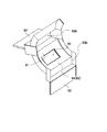
- FIG. 3 is a perspective view showing the main roll cover 8
- FIG. 3 (a) is a view showing a state in which the main roll cover 8 is incorporated in the main roll 5
- FIG. 4 is a diagram showing a state in which the main roll 5 is removed in FIG. 4 is a diagram showing a half-split state of the main roll cover 8
- FIG. 5 is an enlarged view of the vicinity of the main roll cover 8 of the thin film forming apparatus 1.
- the main roll cover 8 is formed in a curved shape so as to face the entire outer peripheral surface 51 of the main roll 5, and both end portions of the roll facing surface 81 are side surfaces of the main roll 5. Is formed so as to cover a part of the side surface of the main roll 5.
- a slight gap is formed with respect to the main roll 5 in the portion that covers the roll facing surface 81 and the side surface of the main roll 5. That is, since the main roll cover 8 and the main roll 5 are not in contact with each other, the belt-like base material 2 supplied to the main roll 5 along the outer peripheral surface 51 is not in contact with the main roll cover 8, and the roll facing surface. It travels through a cover gap 84 formed by 81 and the main roll 5.
- the film forming chamber communication portion 82 is a flow path that communicates with each film forming chamber 7, and the belt-like base material 2 that runs along the outer peripheral surface 51 of the main roll 5 in this flow path is used. Is formed in the film forming chamber 7 to form a thin film on the belt-like substrate 2.
- the film forming chamber communication portion 82 is formed by an opening 85 formed in the roll facing surface 81 and a cover gap 84 formed by the roll facing surface 81 and the outer peripheral surface 51 of the main roll 5. Yes.
- the opening 85 allows the band-shaped substrate 2 to face the film forming chamber 7.
- the opening 85 is formed such that a rectangular region having a width dimension corresponding to the film forming region of the belt-like substrate 2 penetrates the roll facing surface 81 in the thickness direction. That is, since the non-film forming area
- the roll facing surface 81 has an opening 85 corresponding to the film forming region at the center in the width direction, and a mask portion 85a corresponding to the non-film forming region at both ends in the width direction. That is, the opening 85 is formed so as to penetrate the roll facing surface 81 while leaving a portion corresponding to the mask portion 85a.
- the traveling direction dimension of the strip-shaped substrate 2 in the opening 85 is appropriately set according to the thickness of the thin film formed on the strip-shaped substrate 2 in relation to the traveling speed of the strip-shaped substrate 2.
- the cover gap 84 is a gap formed by the roll facing surface 81 of the main roll cover 8 and the outer peripheral surface 51 of the main roll 5, and the roll facing surface 81 of the main roll cover 8 has an outer periphery of the main roll 5. It is provided so as to be as close to the surface 51 as possible.
- the cover gap 84 is formed along the outer peripheral surface 51 of the main roll 5 and is continuously formed between the partition portions 62. That is, the cover gap 84 is continuously provided from the opening 85 to the manifold portion 83b described later.
- the dimension of the cover gap 84 is such that the belt-like substrate 2 does not come into contact with the main roll cover 8 even when the belt-like substrate 2 having a thin film formed on the outer peripheral surface 51 of the main roll 5 is along.
- the source gas in the film forming chamber 7 comes into contact with the belt-like substrate 2 through the opening 85, and thus the first film forming chamber 7a. And by passing through the second film forming chamber 7b, a predetermined thin film is formed on the belt-like substrate 2.
- the manifold part 83b is a part to which the adjacent film forming chamber communication part 82 is connected, and is formed to have a larger space than the cover gap 84 of the film forming chamber communication part 82.
- An inert gas supply pipe 91 that supplies an inert gas is connected to the manifold portion 83b.
- This inert gas supply pipe 91 is connected to an inert gas tank 92, and the amount of inert gas supplied to the manifold portion 83b can be adjusted by adjusting a valve 93 provided in the pipe path. .
- the supply amount of the inert gas is adjusted so that the pressure in the manifold portion 83 b is higher than the pressure in the film forming chamber 7.
- the pressure is set to be higher than at least the two adjacent film forming chambers 7 that communicate with each other through the film forming chamber communication portion 82 as viewed from the manifold portion 83b.
- argon gas is supplied as an inert gas.
- an inert gas other than argon gas may be used as long as it does not affect film formation.
- the manifold portion 83 b is filled with the inert gas, and the pressure in the main roll cover 8 becomes higher than the pressure in the film forming chamber 7. Then, the inert gas in the manifold part 83b enters the adjacent film forming chamber 7 through the film forming chamber communication part 82 (broken line in FIG. 5). Accordingly, even if the source gas supplied to the film forming chamber 7 tries to enter the film forming chamber communication portion 82, the pressure in the main roll cover 8 is set high, so that the film forming chamber communication portion 82 is inactive.
- the gas is pushed back to the original film forming chamber 7 and the intrusion into the other film forming chamber 7 is suppressed. Since the gas supplied to the manifold portion 83b is an inert gas, even if the gas enters the film forming chamber 7, the film forming is not affected at all.
- the belt-like substrate 2 wound around the delivery roll unit 31 of the substrate delivery unit 3 is set, the belt-like substrate 2 is set along the outer peripheral surface 51 of the main roll 5, and then the substrate winding unit 4. It spans the take-up roll unit 41. Then, the vacuum pumps 61 and 71 of the main roll chamber 6 and the film forming chamber 7 are operated to reach a predetermined degree of vacuum in each chamber.
- a high frequency power source is applied to the plasma electrode 72 and a source gas is supplied from a source gas pipe 73 of the film forming chamber 7.
- a source gas is supplied from a source gas pipe 73 of the film forming chamber 7.
- the degree of vacuum in the film forming chamber 7 becomes worse than before the source gas is supplied.
- the pressure P1 of the first film forming chamber 7a is larger than the pressure P2 of the second film forming chamber 7b.
- the pressure P0 of the main roll chamber 6 hardly changes because the degree of vacuum is maintained. Therefore, as a result, the relationship between the pressures is P1> P2 ⁇ P0.
- the base material feeding section 3 and the base material winding section 4 are driven to convey the belt-shaped base material 2 at a predetermined speed.
- the source gas activated by exposing the source gas to the plasma atmosphere touches the strip-shaped substrate 2 through the opening 85 of the main roll cover 8, and the surface of the strip-shaped substrate 2 is exposed to the first surface.
- One thin film is formed. That is, the belt-like base material 2 is conveyed in the cover gap 84 along the outer peripheral surface 51 of the main roll 5 and touches the raw material gas entering from the opening 85, so that the surface of the belt-like base material 2 has a longitudinal direction. A 1st thin film is formed over.
- the opening area (cross-sectional area) of the cover gap 84 is formed small and there is a distance to the manifold portion 83b, the pressure loss increases, and the source gas entering from the opening 85 is the first. Active outflow from the film forming chamber 7a can be suppressed.
- the inert gas is supplied so that the pressure in the main roll cover 8 is set to be higher than that in the film forming chamber 7. Therefore, the source gas that has entered through the opening 85 is inactive. The active gas is pushed back into the film forming chamber 7 to prevent entry into the manifold portion 83b. That is, it is possible to suppress the source gas of the first film forming chamber 7a from entering the second film forming chamber 7b through the film forming chamber communication portion 82.
- the second thin film is formed on the first thin film by being exposed to the source gas 7b.
- belt-shaped base material 2 (product base material) is wound up by the base-material winding part 4.
- the pressure in the main roll cover 8 is set higher than that in the film forming chamber 7 as in the case of the raw material gas in the first film forming chamber 7a.
- the source gas that has entered from the opening 85 is pushed back into the second film-forming chamber 7b by the inert gas, and entry into the manifold 83b is suppressed.
- the main roll cover 8 is provided on the main roll 5, and the pressure in the main roll cover 8 is set higher than the pressure in the film forming chamber 7, so that the raw materials used in each film forming chamber 7 are adjacent to each other.
- the entry into the film forming chamber 7 can be suppressed. Therefore, deterioration of the film quality due to mixing of the raw material gases in different film forming chambers 7 can be suppressed, the purity of the raw material gas used in each film forming chamber 7 can be maintained, and the formed film quality can be stabilized. .
- the manifold portion 83b may be directly supplied into the main roll cover 8 without providing the manifold portion 83b.
- the roll facing surface 81 is configured to be continuously formed including the portion where the main roll cover 8 is connected to the partition 62, and between the openings 85 of the film forming chamber 7.
- the structure which connects the inert gas supply piping 91 to the roll opposing surface 81 located may be sufficient.
- the pressure in the main roll cover 8 formed by the main roll cover 8 and the outer peripheral surface 51 of the main roll 5 is reduced by the inert gas supplied from the inert gas supply pipe 91. If the pressure is adjusted to be higher than the pressure of 7, the raw material used in the film forming chamber 7 can be prevented from entering the adjacent film forming chamber 7.
- two film forming chambers 7 are described.
- three or more film forming chambers 7 may be provided by increasing the number of partitions 62.
Landscapes
- Chemical & Material Sciences (AREA)
- Engineering & Computer Science (AREA)
- Chemical Kinetics & Catalysis (AREA)
- Materials Engineering (AREA)
- Mechanical Engineering (AREA)
- Metallurgy (AREA)
- Organic Chemistry (AREA)
- General Chemical & Material Sciences (AREA)
- Physics & Mathematics (AREA)
- Plasma & Fusion (AREA)
- Physical Vapour Deposition (AREA)
- Chemical Vapour Deposition (AREA)
Abstract
Description
2 帯状基材
5 メインロール
6 メインロールチャンバ
7 製膜チャンバ
8 メインロールカバー
51 外周面
62 間仕切り部
81 ロール対向面
82 製膜チャンバ連通部
83b マニホールド部
84 カバー隙間
85 開口部
91 不活性ガス供給配管
92 不活性ガスタンク
Claims (4)
- 帯状基材をメインロールの外周面に沿わせた状態で帯状基材を搬送しつつ表面処理を行うことにより帯状基材上に薄膜を形成する薄膜形成装置であって、
メインロールを収容するメインロールチャンバと、
メインロールの外径側に間仕切り部を配置することにより、メインロールの周方向に配列される複数の製膜チャンバと、
を備え、
前記間仕切り部には、帯状基材が走行するメインロールの外周面を覆うメインロールカバーが設けられ、このメインロールカバーには、前記製膜チャンバに連通する製膜チャンバ連通部が形成されており、前記メインロールカバーとメインロールの外周面とで形成されるメインロールカバー内の圧力が前記製膜チャンバの圧力よりも高くなるように設定されていることを特徴とする薄膜形成装置。 - 前記メインロールカバーは、メインロールの外周面に対向するロール対向面を有しており、前記製膜チャンバ連通部は、製膜チャンバに開口する開口部と、前記ロール対向面と前記メインロール外周面とで形成されるカバー隙間と、によって形成されていることを特徴とする請求項1に記載の薄膜形成装置。
- 前記メインロールカバーは、隣接する間仕切り部に連続的に設けられており、前記ロール対向面には、製膜領域に応じて貫通して形成される前記開口部と、非製膜領域に応じて形成されるマスク部とが形成されていることを特徴とする請求項2に記載の薄膜形成装置。
- 前記メインロールカバー内に不活性ガスが供給されることにより、前記メインロールカバー内の圧力が前記製膜チャンバの圧力よりも高くなるように設定されていることを特徴とする請求項1~3のいずれかに記載の薄膜形成装置。
Priority Applications (3)
| Application Number | Priority Date | Filing Date | Title |
|---|---|---|---|
| KR1020167026887A KR20170021222A (ko) | 2014-05-09 | 2015-02-23 | 박막 형성 장치 |
| US15/306,416 US10351947B2 (en) | 2014-05-09 | 2015-02-23 | Thin-film forming device |
| CN201580020201.0A CN106232868B (zh) | 2014-05-09 | 2015-02-23 | 薄膜形成装置 |
Applications Claiming Priority (2)
| Application Number | Priority Date | Filing Date | Title |
|---|---|---|---|
| JP2014-097511 | 2014-05-09 | ||
| JP2014097511A JP6347662B2 (ja) | 2014-05-09 | 2014-05-09 | 薄膜形成装置 |
Publications (1)
| Publication Number | Publication Date |
|---|---|
| WO2015170499A1 true WO2015170499A1 (ja) | 2015-11-12 |
Family
ID=54392353
Family Applications (1)
| Application Number | Title | Priority Date | Filing Date |
|---|---|---|---|
| PCT/JP2015/054985 Ceased WO2015170499A1 (ja) | 2014-05-09 | 2015-02-23 | 薄膜形成装置 |
Country Status (5)
| Country | Link |
|---|---|
| US (1) | US10351947B2 (ja) |
| JP (1) | JP6347662B2 (ja) |
| KR (1) | KR20170021222A (ja) |
| CN (1) | CN106232868B (ja) |
| WO (1) | WO2015170499A1 (ja) |
Families Citing this family (6)
| Publication number | Priority date | Publication date | Assignee | Title |
|---|---|---|---|---|
| USD938132S1 (en) * | 2015-09-08 | 2021-12-14 | Justin A. Mark | Food product |
| USD938131S1 (en) * | 2015-09-08 | 2021-12-14 | Justin A. Mark | Food product |
| JP6973718B2 (ja) | 2018-03-19 | 2021-12-01 | 株式会社神戸製鋼所 | プラズマcvd装置、及びフィルムの製造方法 |
| USD937532S1 (en) * | 2018-08-20 | 2021-12-07 | Justin Mark | Home plate shaped sandwich |
| CN112368413B (zh) * | 2019-03-12 | 2022-04-29 | 株式会社爱发科 | 真空蒸镀装置 |
| USD1020164S1 (en) * | 2022-05-12 | 2024-04-02 | David A Zavala | Confectionary item |
Citations (6)
| Publication number | Priority date | Publication date | Assignee | Title |
|---|---|---|---|---|
| JP2001023907A (ja) * | 1999-07-07 | 2001-01-26 | Mitsubishi Heavy Ind Ltd | 成膜装置 |
| JP2001303249A (ja) * | 2000-04-19 | 2001-10-31 | Hirano Koon Kk | 帯状シート材の表面処理装置 |
| WO2010052846A1 (ja) * | 2008-11-05 | 2010-05-14 | 株式会社アルバック | 巻取式真空処理装置 |
| JP2011042848A (ja) * | 2009-08-24 | 2011-03-03 | Fujifilm Corp | 成膜装置 |
| JP2013194253A (ja) * | 2012-03-16 | 2013-09-30 | Ulvac Japan Ltd | 真空処理装置 |
| JP2014065932A (ja) * | 2012-09-25 | 2014-04-17 | Toray Eng Co Ltd | 薄膜形成装置 |
Family Cites Families (4)
| Publication number | Priority date | Publication date | Assignee | Title |
|---|---|---|---|---|
| US20060159844A1 (en) * | 2005-01-18 | 2006-07-20 | Fuji Photo Film Co., Ltd. | Process and apparatus for producing magnetic recording medium |
| JP2007186775A (ja) | 2006-01-16 | 2007-07-26 | Bridgestone Corp | 成膜方法及び装置 |
| JP5694023B2 (ja) * | 2011-03-23 | 2015-04-01 | 小島プレス工業株式会社 | 積層構造体の製造装置 |
| WO2013082279A1 (en) * | 2011-11-29 | 2013-06-06 | Itn Energy Systems, Inc. | Multi-zone modular coater |
-
2014
- 2014-05-09 JP JP2014097511A patent/JP6347662B2/ja active Active
-
2015
- 2015-02-23 CN CN201580020201.0A patent/CN106232868B/zh active Active
- 2015-02-23 US US15/306,416 patent/US10351947B2/en active Active
- 2015-02-23 KR KR1020167026887A patent/KR20170021222A/ko not_active Ceased
- 2015-02-23 WO PCT/JP2015/054985 patent/WO2015170499A1/ja not_active Ceased
Patent Citations (6)
| Publication number | Priority date | Publication date | Assignee | Title |
|---|---|---|---|---|
| JP2001023907A (ja) * | 1999-07-07 | 2001-01-26 | Mitsubishi Heavy Ind Ltd | 成膜装置 |
| JP2001303249A (ja) * | 2000-04-19 | 2001-10-31 | Hirano Koon Kk | 帯状シート材の表面処理装置 |
| WO2010052846A1 (ja) * | 2008-11-05 | 2010-05-14 | 株式会社アルバック | 巻取式真空処理装置 |
| JP2011042848A (ja) * | 2009-08-24 | 2011-03-03 | Fujifilm Corp | 成膜装置 |
| JP2013194253A (ja) * | 2012-03-16 | 2013-09-30 | Ulvac Japan Ltd | 真空処理装置 |
| JP2014065932A (ja) * | 2012-09-25 | 2014-04-17 | Toray Eng Co Ltd | 薄膜形成装置 |
Also Published As
| Publication number | Publication date |
|---|---|
| JP2015214726A (ja) | 2015-12-03 |
| KR20170021222A (ko) | 2017-02-27 |
| US20170044662A1 (en) | 2017-02-16 |
| CN106232868B (zh) | 2019-03-01 |
| CN106232868A (zh) | 2016-12-14 |
| US10351947B2 (en) | 2019-07-16 |
| JP6347662B2 (ja) | 2018-06-27 |
Similar Documents
| Publication | Publication Date | Title |
|---|---|---|
| JP6347662B2 (ja) | 薄膜形成装置 | |
| JP5665290B2 (ja) | 成膜装置 | |
| JP5182610B2 (ja) | 薄膜太陽電池の製造装置 | |
| JP5486249B2 (ja) | 成膜方法 | |
| US8999062B2 (en) | Film depositing apparatus | |
| US20090220803A1 (en) | Film depositing apparatus, gas barrier film, and process for producing gas barrier films | |
| JP6001975B2 (ja) | 薄膜形成装置 | |
| JP6376685B2 (ja) | 薄膜形成装置および薄膜形成方法 | |
| JP2008031505A (ja) | 成膜装置および成膜方法 | |
| KR102360686B1 (ko) | 밀봉막의 형성 방법 및 밀봉막 | |
| JP2016017198A (ja) | 薄膜形成装置および薄膜形成方法 | |
| JP2012219322A (ja) | 巻取式成膜装置及び巻取式成膜方法 | |
| JP6209039B2 (ja) | 薄膜形成装置 | |
| JP2014122419A (ja) | プラズマcvd装置 | |
| JP2017155298A (ja) | 薄膜形成装置 | |
| CN114630925B (zh) | 成膜装置 | |
| JP2020152954A (ja) | 成膜装置 | |
| JP6419428B2 (ja) | 差動排気システム | |
| JP2018168453A (ja) | 薄膜形成装置 | |
| JP2019167609A (ja) | 薄膜形成装置 | |
| JP2020063467A (ja) | 薄膜形成装置 | |
| JP2018145444A (ja) | 薄膜形成装置 | |
| JP2009052103A (ja) | 成膜装置 | |
| JP2016060942A (ja) | 薄膜形成装置、薄膜形成方法および薄膜付き基材 | |
| JP2015010244A (ja) | 差動排気システム |
Legal Events
| Date | Code | Title | Description |
|---|---|---|---|
| 121 | Ep: the epo has been informed by wipo that ep was designated in this application |
Ref document number: 15789599 Country of ref document: EP Kind code of ref document: A1 |
|
| ENP | Entry into the national phase |
Ref document number: 20167026887 Country of ref document: KR Kind code of ref document: A |
|
| WWE | Wipo information: entry into national phase |
Ref document number: 15306416 Country of ref document: US |
|
| NENP | Non-entry into the national phase |
Ref country code: DE |
|
| 32PN | Ep: public notification in the ep bulletin as address of the adressee cannot be established |
Free format text: NOTING OF LOSS OF RIGHTS PURSUANT TO RULE 112(1) EPC (( EPO FORM 1205A DATED 16-02-2017) |
|
| 122 | Ep: pct application non-entry in european phase |
Ref document number: 15789599 Country of ref document: EP Kind code of ref document: A1 |