WO2015163359A1 - 電動粉挽き機 - Google Patents
電動粉挽き機 Download PDFInfo
- Publication number
- WO2015163359A1 WO2015163359A1 PCT/JP2015/062217 JP2015062217W WO2015163359A1 WO 2015163359 A1 WO2015163359 A1 WO 2015163359A1 JP 2015062217 W JP2015062217 W JP 2015062217W WO 2015163359 A1 WO2015163359 A1 WO 2015163359A1
- Authority
- WO
- WIPO (PCT)
- Prior art keywords
- grinding
- unit
- crushing
- clock
- stirring
- Prior art date
- Legal status (The legal status is an assumption and is not a legal conclusion. Google has not performed a legal analysis and makes no representation as to the accuracy of the status listed.)
- Ceased
Links
Images







Classifications
-
- B—PERFORMING OPERATIONS; TRANSPORTING
- B02—CRUSHING, PULVERISING, OR DISINTEGRATING; PREPARATORY TREATMENT OF GRAIN FOR MILLING
- B02C—CRUSHING, PULVERISING, OR DISINTEGRATING IN GENERAL; MILLING GRAIN
- B02C7/00—Crushing or disintegrating by disc mills
- B02C7/11—Details
- B02C7/16—Driving mechanisms
-
- A—HUMAN NECESSITIES
- A23—FOODS OR FOODSTUFFS; TREATMENT THEREOF, NOT COVERED BY OTHER CLASSES
- A23F—COFFEE; TEA; THEIR SUBSTITUTES; MANUFACTURE, PREPARATION, OR INFUSION THEREOF
- A23F3/00—Tea; Tea substitutes; Preparations thereof
- A23F3/06—Treating tea before extraction; Preparations produced thereby
- A23F3/12—Rolling or shredding tea leaves
-
- A—HUMAN NECESSITIES
- A23—FOODS OR FOODSTUFFS; TREATMENT THEREOF, NOT COVERED BY OTHER CLASSES
- A23F—COFFEE; TEA; THEIR SUBSTITUTES; MANUFACTURE, PREPARATION, OR INFUSION THEREOF
- A23F3/00—Tea; Tea substitutes; Preparations thereof
- A23F3/16—Tea extraction; Tea extracts; Treating tea extract; Making instant tea
- A23F3/18—Extraction of water soluble tea constituents
-
- A—HUMAN NECESSITIES
- A47—FURNITURE; DOMESTIC ARTICLES OR APPLIANCES; COFFEE MILLS; SPICE MILLS; SUCTION CLEANERS IN GENERAL
- A47J—KITCHEN EQUIPMENT; COFFEE MILLS; SPICE MILLS; APPARATUS FOR MAKING BEVERAGES
- A47J31/00—Apparatus for making beverages
- A47J31/42—Beverage-making apparatus with incorporated grinding or roasting means for coffee
-
- A—HUMAN NECESSITIES
- A47—FURNITURE; DOMESTIC ARTICLES OR APPLIANCES; COFFEE MILLS; SPICE MILLS; SUCTION CLEANERS IN GENERAL
- A47J—KITCHEN EQUIPMENT; COFFEE MILLS; SPICE MILLS; APPARATUS FOR MAKING BEVERAGES
- A47J42/00—Coffee mills; Spice mills
- A47J42/12—Coffee mills; Spice mills having grinding discs
- A47J42/20—Grinding discs
-
- A—HUMAN NECESSITIES
- A47—FURNITURE; DOMESTIC ARTICLES OR APPLIANCES; COFFEE MILLS; SPICE MILLS; SUCTION CLEANERS IN GENERAL
- A47J—KITCHEN EQUIPMENT; COFFEE MILLS; SPICE MILLS; APPARATUS FOR MAKING BEVERAGES
- A47J42/00—Coffee mills; Spice mills
- A47J42/38—Parts or details
- A47J42/44—Automatic starting or stopping devices; Warning devices
Definitions
- the present disclosure relates to an electric grinder, and more particularly to an electric grinder that pulverizes food by relatively moving two or more members that are in contact with each other.
- Patent Document 1 Japanese Patent Application Laid-Open No. 2005-199242
- the electric grinder that pulverizes the food by relatively moving the members that are joined together, such as the pulverization mechanism using the above mortar, it operates by friction. It is predicted that the part to be heated will become high temperature. For this reason, in the electric grinder, it is preferable to take measures to prevent the part from becoming too hot.
- the present disclosure has been devised in view of such circumstances, and an object thereof is to provide an electric grinder that can suppress an increase in temperature of a crushing mechanism.
- an electric grinder for crushing food the crushing mechanism for crushing food by relatively moving two or more members in contact with each other and generating powder of the food
- a control unit configured to control the operation of the crushing mechanism, and the control unit enters a crushing suppression mode for suppressing the crushing operation of the food by the crushing mechanism after crushing the food of the crushing mechanism.
- an electric grinder that is configured to perform a process for suppressing the pulverization operation by the pulverization mechanism until a predetermined condition is satisfied.
- the predetermined condition is a lapse of a predetermined time.
- the control unit is configured to be supplied with power from an external power source, and the electric grinder is an internal unit for supplying power to the control unit when power supply from the external power source is interrupted.
- a power supply is further provided, and the control unit is configured to execute the pulverization control mode using the power supplied from the internal power supply when the power supply from the external power supply is interrupted.
- control unit is configured to set a predetermined condition based on a mode of pulverizing the food by the pulverizing mechanism.
- the electric grinder includes a first oscillation circuit for oscillating a clock supplied with power from an external power supply, and a second oscillation circuit for oscillating a clock supplied with power from an internal power supply.
- storage means for storing information for correcting the clock of the second oscillation circuit based on the clock of the first oscillation circuit, and the control unit is supplied with power from the internal power supply and performs processing Is executed, the clock generated by the second oscillation circuit is corrected using information and used.
- the electric grinder can transition to the crushing suppression mode for suppressing the food crushing operation by the crushing mechanism. Thereby, it can avoid that the temperature in the said grinding
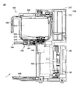
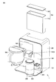
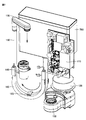
- FIG. 2 is a cross-sectional view taken along line II-II in FIG. It is a whole perspective view which shows the schematic component of the drink manufacturing apparatus in 1st Embodiment. It is a 1st manufacturing flow which shows Japanese tea discharge using the drink manufacturing apparatus in 1st Embodiment. It is a 2nd manufacturing flow which shows Japanese tea discharge using the drink manufacturing apparatus in 1st Embodiment. It is a 3rd manufacturing flow which shows Japanese tea discharge using the drink manufacturing apparatus in 1st Embodiment. It is a perspective view which shows only the internal structure of the drink manufacturing apparatus in 1st Embodiment.
- a beverage production apparatus that is an embodiment of an electric grinder according to the present disclosure will be described with reference to the drawings.
- the beverage production apparatus heats the liquid to produce a beverage by mixing the powder produced by the crushing mechanism with the crushing mechanism for producing the food powder by crushing the food. Heating mechanism.
- the electric grinder need only include at least a pulverizing mechanism, and may not include a heating mechanism.
- tea leaves means a solid state before pulverization
- powdered tea leaves mean crushed tea leaves
- tea means a beverage in which powdered tea leaves and hot water are agitated (mixed). To do.
- FIG. 1 is an overall perspective view of the beverage production apparatus 1.
- 2 is a cross-sectional view taken along line II-II in FIG.
- FIG. 3 is an overall perspective view showing schematic components of the beverage production apparatus 1.
- the beverage production apparatus 1 uses tea leaves as an object to be crushed and crushes the tea leaves to obtain tea leaf powder. Tea is produced as a beverage using the obtained tea leaf powder.
- the beverage production apparatus 1 includes an apparatus main body 100, an operation panel 101, a grinding unit 300, a stirring unit 500, a water tank 700, a tea leaf powder receiving tray 800, and a mounting base 900.
- the mounting base 900 is provided so as to protrude forward in the lower front side of the apparatus main body 100, and a cup (not shown) and the tea leaf powder tray 800 can be mounted thereon.
- the grinding unit 300 is detachably mounted on a grinding unit mounting area 180 provided on the front side of the apparatus main body 100.
- a grinding driving force coupling mechanism 130 is provided so as to protrude forward, and the grinding unit 300 is detachably attached to the grinding driving force coupling mechanism 130.
- the grinding unit 300 is connected to the grinding driving force coupling mechanism 130 to obtain a driving force for grinding tea leaves that are objects to be ground.
- Tea leaves put into the inside of the grinding unit 300 from the upper part of the grinding unit 300 are finely pulverized in the inside of the grinding unit 300, and the tea leaves are placed on the tea leaf powder tray 800 placed below the grinding unit 300 as tea leaf powder. Fall and collect.
- the agitation unit 500 is detachably attached to the agitation unit attachment region 190 provided on the front side of the apparatus main body 100.
- a stirring motor non-contact table 140A is provided, and a stirring blade 550 (see FIG. 13 described later) provided in the stirring unit 500 is rotationally driven using magnetic force.
- a hot water supply nozzle 170 (see FIG. 7) is provided in the upper part of the stirring unit mounting region 190 of the apparatus main body 100.
- the water in the water tank 700 is raised to a predetermined temperature, and hot water is supplied from the hot water supply nozzle 170 into the stirring tank 510.
- the stirring tank 510 hot water created in the apparatus main body 100 and the tea leaf powder obtained by the grinding unit 300 are charged, and the hot water and the tea leaf powder are stirred by the stirring blade 550 of the stirring tank 510. .
- tea is manufactured in the stirring tank 510.
- the agitation tank 510 is an example of an accommodating portion for accommodating liquid and powder.
- the Japanese tea produced in the stirring unit 500 is a cup (not shown) placed on the placement base 900 by operating the operation lever 542 of the discharge opening / closing mechanism 540 provided below the stirring unit 500. You can pour tea.
- FIG. 4 to FIG. 6 are diagrams showing first to third production flows showing Japanese tea discharge using the beverage production apparatus 1. Note that a predetermined amount of Japanese tea leaves is input to the grinding unit 300, and a predetermined amount of water is stored in the water tank 700.
- This first production flow is a flow in which tea leaf crushing in the grinding unit 300 and hot water supply from the apparatus main body 100 to the stirring unit 500 are performed in parallel.
- tea leaf grinding by the grinding unit 300 in step S1 is started, while hot water supply from the apparatus main body 100 to the stirring unit 500 in step S3 is started.
- tea leaf grinding by the grinding unit 300 is completed, and hot water supply from the apparatus main body 100 to the stirring unit 500 in step S4 is completed.
- Step S5 the tea leaf powder obtained in Step S2 is put into the stirring unit 500 by the user.
- step S6 stirring of the tea leaf powder and hot water in the stirring unit 500 is started.
- step S7 stirring of the tea leaf powder and hot water in the stirring unit 500 ends.
- step S ⁇ b> 8 the user operates the operation lever 542 of the discharge port opening / closing mechanism 540 provided below the stirring unit 500 to discharge tea to the cup placed on the placement base 900. .
- This second manufacturing flow is a flow in which hot water is supplied from the apparatus main body 100 to the stirring unit 500 after the tea leaves in the grinding unit 300 are crushed.
- step S1 the beverage production apparatus 1 starts grinding of tea leaves by the grinding unit 300.
- step S2 the grinding of tea leaves by the grinding unit 300 ends.
- step S3 the tea leaf powder obtained in step S2 is put into the stirring unit 500 by the user.
- step S4 hot water supply from the apparatus main body 100 to the stirring unit 500 is started.
- step S5 the hot water supply from the apparatus main body 100 to the stirring unit 500 is completed.
- step S6 stirring of the tea leaf powder and hot water in the stirring unit 500 is started.
- step S7 stirring of the tea leaf powder and hot water in the stirring unit 500 ends.
- step S ⁇ b> 8 the user operates the operation lever 542 of the discharge port opening / closing mechanism 540 provided below the stirring unit 500 to discharge tea to the cup placed on the placement base 900. .
- the third manufacturing flow includes a step of cooling hot water by stirring in the stirring unit 500.
- tea leaf grinding by the grinding unit 300 in step S1 and hot water supply from the apparatus main body 100 to the stirring unit 500 in step S3 are started simultaneously.
- the hot water supply from the apparatus main body 100 to the stirring unit 500 in step S4 is completed.
- step S2 tea leaf grinding by the grinding unit 300 is completed, and in step S5, the stirring unit 500 starts cooling and stirring the hot water supply.
- step S6 the cooling and stirring of the hot water supply is completed in the stirring unit 500.
- control may be performed so that the timing of the end of grinding and the timing of the end of cooling and stirring are matched.
- step S7 the tea leaf powder obtained in step S2 is put into the stirring unit 500 by the user.
- step S8 stirring of the tea leaf powder and hot water in the stirring unit 500 is started.
- step S9 stirring of the tea leaf powder and hot water in the stirring unit 500 ends.
- step 40 the user operates the operation lever 542 of the discharge port opening / closing mechanism 540 provided below the stirring unit 500 to discharge tea to the cup placed on the placement base 900. .
- FIG. 7 is a perspective view showing only the internal structure of the beverage production apparatus 1.
- a control unit 110 using a printed wiring board on which electronic components are mounted is disposed on the front side of the water tank 700.
- the tea production flow is executed by the control unit 110 based on the input of the start signal by the user.
- a grinding motor unit 120 for applying a driving force to the grinding unit 300 is disposed below the control unit 110 (printed wiring board).
- a grinding driving force coupling mechanism 130 is provided at a lower position of the grinding motor unit 120 so as to protrude forward, and the driving force of the grinding motor unit 120 is transmitted to the grinding unit 300. Yes.
- the bottom surface of the water tank 700 is connected to one end of a hot water supply pipe 150 that extends downward from the bottom surface and extends upward in a U shape.
- a hot water supply nozzle 170 for pouring hot water into the stirring tank 510 of the stirring unit 500 is connected to the upper end of the hot water supply pipe 150.
- a U-shaped heater 160 for heating water passing through the hot water supply pipe 150 is attached to an intermediate region of the hot water supply pipe 150.
- a thermistor 123 for measuring the temperature of water passing through the hot water supply pipe 150 is attached to the hot water supply pipe 150.
- the beverage production apparatus 1 is provided with a pump (pump 261 in FIG. 14) that sends water (hot water) in the hot water supply pipe 150 to the hot water supply nozzle 170.
- FIG. 8 is an enlarged view of the structure around the grinding motor unit 120.
- a grinding motor unit 120 includes a mill motor 121, a metal plate 122A for attaching the mill motor 121 to the grinding driving force coupling mechanism 130, and a thermistor 122 attached to the metal plate 122A.
- the mill motor 121 is attached to the metal plate 122A. Heat is transmitted to the thermistor 122 from the mill motor 121 through the metal plate 122A.
- the thermistor 122 can measure the temperature of the outer surface of the mill motor 121.
- FIG. 9 is a perspective view of the grinding unit 300.
- FIG. 10 is an exploded perspective view of the grinding unit 300.
- FIG. 11 is a longitudinal sectional view of the grinding unit 300.
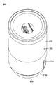
- the grinding unit 300 includes a grinding case 310 having a cylindrical shape as a whole, and a connecting window 310w into which the grinding driving force coupling mechanism 130 is inserted is provided on the lower side surface. At the lowermost end portion of the grinding case 310, a takeout port 312a from which the tea leaf powder crushed by the grinding unit 300 is taken out (dropped) is formed.
- a dust scraper 340 In the grinding case 310, a dust scraper 340, a lower die 350, and an upper die 360 are provided in this order from below.
- a grinding shaft 345 extending downward is provided on the lower surface of the dust scraper 340, and the grinding shaft 345 is connected to the grinding driving force coupling mechanism 130.
- a core 355 extending upward along the rotational axis is provided at the center of the lower die 350.
- the upper die 360 is held by an upper die holding member 370, and a spring 380 and a spring holding member 390 that press the upper die 360 downward are housed inside the upper die holding member 370.
- the core 355 provided in the lower die 350 extends upward so as to penetrate the upper die 360.
- the radius r of the upper die 360 and the lower die 350 in the first embodiment is about 15 mm to 30 mm, and the thickness t1 of each of the upper die 360 and the lower die 350 is about 8 mm.
- the relative rotational speed W of the upper die 360 and the lower die 350 is about 60 rpm ⁇ W ⁇ 150 rpm.
- FIG. 12 is a perspective view of the stirring unit 500.
- FIG. 13 is a longitudinal sectional view of the stirring unit 500.
- the stirring unit 500 includes a stirring tank 510.
- the stirring tank 510 includes a resin exterior holder 511 and a heat retaining tank 512 held by the exterior holder 511.
- the exterior holder 511 is provided with a grip 520 that is integrally formed of resin.
- a stirring cover 530 for opening and closing the opening is provided at the upper surface opening of the stirring tank 510.
- the stirring cover 530 is provided with a powder inlet 531 for charging the tea leaf powder crushed by the grinding unit 300 and a hot water outlet 532 through which hot water formed by the apparatus main body 100 is poured from the hot water nozzle 170. .
- a stirring blade 550 is placed on the bottom of the stirring tank 510.
- the stirring unit 500 further includes a stirring motor unit 140 including a stirring motor 141 (see FIG. 14) for rotating the stirring blade 550.
- a rotating shaft 560 extending upward is provided at the bottom of the stirring tank 510, and the bearing portion 551 of the stirring blade 550 is inserted into the rotating shaft 560.
- a magnet is embedded in the stirring blade 550.
- the magnet embedded in the stirring blade 550 and the magnet provided on the stirring motor unit 140 side are magnetically coupled in a non-contact state, so that the rotational driving force of the stirring motor unit 140 is increased. , Transmitted to the stirring blade 550.
- a discharge port 541 for discharging the stirred tea is provided at the bottom of the stirring tank 510.
- the discharge port 541 is provided with a discharge port opening / closing mechanism 540.
- the discharge port opening / closing mechanism 540 includes an open / close nozzle 543 inserted into the discharge port 541 and an operation lever 542 for controlling the position of the open / close nozzle 543 so that the discharge port 541 can be opened and closed.
- the opening / closing nozzle 543 is biased so as to close the discharge port 541 by a biasing member (not shown) such as a spring in a normal state.
- a biasing member such as a spring in a normal state.
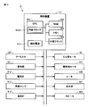
- FIG. 14 is a diagram illustrating an example of a hardware configuration of the beverage manufacturing apparatus 1 according to the first embodiment.
- the beverage production device 1 includes a control device 111 for controlling the operation of the beverage production device 1.
- the control device 111 is located in the control unit 110 (see FIG. 7).
- the arrangement of the control device 111 is not limited to this.
- the control device 111 includes a CPU 901 for executing control by executing a program, a RAM (Random Access Memory) 902 that functions as a work area of the CPU 901, and a memory for storing data such as programs non-temporarily. 903, an external clock (clock oscillation circuit) 904 is provided.
- the memory 903 is configured by, for example, an EEPROM (Electrically Erasable Programmable Read-Only Memory).
- the control device 111 is connected to the thermistor 122, the mill motor 121, the stirring motor 141, the heater 160, and the pump 261 via a bus or the like.
- the beverage production apparatus 1 further includes an operation unit 911, an ammeter 912, a rotation sensor 913, a thermometer 914, a display unit 921, an external clock 904, an auxiliary power source 910, and a speaker 922.
- the operation unit 911 is operated to input information to the CPU 901, and includes, for example, one or more buttons.
- the ammeter 912 measures the current value in the mill motor 121 and inputs it to the CPU 901.
- the rotation sensor 913 measures a rotation signal of the mill motor 121 and inputs it to the CPU 901.
- the thermometer 914 measures the temperature of water stored in the water tank 700 (or water in the hot water supply pipe 150) and inputs the temperature to the CPU 901.
- the thermometer 914 is provided in the inner surface of the cover of the beverage manufacturing apparatus 1, for example, and measures the temperature of the location which exhibits the temperature which can approximate the temperature of the water in the water tank 700.
- the display unit 921 is provided to output information to the outside of the beverage production apparatus 1.
- Display unit 921 is constituted by a plurality of lamps, for example.
- the CPU 901 notifies the end of pulverization of the object to be pulverized, for example, by turning on a predetermined lamp in the display unit 921.
- the speaker 922 outputs sound.
- the CPU 901 notifies the end of crushing of the object to be crushed by outputting sound from the speaker 922.
- the CPU 901 is supplied with electric power from an external power source (not shown) and operates each part of the beverage production apparatus 1.
- the CPU 901 uses the external clock 904 to execute a time measuring operation when power is supplied from the external power source.
- the CPU 901 includes an internal clock 910A.
- the CPU 901 receives the power supply from the auxiliary power supply 910 and uses the internal clock 910A to measure the time.
- Auxiliary power supply 910 is constituted by, for example, a capacitor or a storage battery.
- the CPU 901 can store power in the auxiliary power source 910 with power supplied from an external power source.
- the internal clock 910A has lower power consumption than the external clock 904. Thereby, the auxiliary power supply 910 is realized by a double layer capacitor of about 0.22 Fa (Farad), for example.
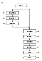
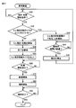
- FIG. 15 is a flowchart of an example of processing executed in the beverage production apparatus 1 for producing a beverage.
- a “mill grinding suppression timer” is used.
- the mill grinding suppression timer is configured to perform the above-described “predetermined time” so that the next grinding operation is not performed for a predetermined time (for example, “30 minutes”) after the grinding motor unit 120 performs the grinding operation. ”Is measured.
- the mill grinding suppression timer is set in step S50, counted down in step S110 or step S140 in the process of FIG. 16 described later, and cleared in step S160.
- the predetermined time may be a time until the lower die 350 and the upper die 360 heated by friction in the grinding operation are cooled to a safe temperature by the atmosphere or the like, and the above “30 minutes” is merely an example. .
- step S10 CPU 901 determines whether or not an instruction to start tea leaf grinding (milling) and water heating is given. If the CPU 901 determines that the instruction has been given, the control proceeds to step S20.
- step S20 the CPU 901 determines whether a milling suppression timer is set. If the CPU 901 determines that it is set, the control proceeds to step S22, and if it is determined that it is not set, the control proceeds to step S30.
- step S22 the CPU 901 notifies that the mill grinding suppression period is in progress, and proceeds to step S24.
- step S24 the CPU 901 determines whether or not a predetermined time (notification time) has elapsed since the start of notification in step S22. If it is determined that the time has elapsed, the control proceeds to step S26.
- a predetermined time notification time
- step S26 the CPU 901 stops the notification started in step S22 and returns the control to step S10.
- step S22 to step S26 even if the CPU 901 receives instructions for starting tea leaf grinding (milling) and water heating in step S10, the grinding motor unit 120 does not perform milling. Wait for the next input of the instruction.
- the notification in step S30 may be an audio output from the speaker 922, or an output of visual information by the display unit 921.
- the notification waits for the elapse of the notification time as in the control in steps S24 and S26. It can end without.
- step S30 the CPU 901 starts the grinding operation by the grinding motor unit 120 and the heating operation by the heater 160. And when both are completed, control will be advanced to step S40.
- step S40 the CPU 901 notifies the completion of the grinding operation and the heating operation.
- the notification is realized by, for example, display by the display unit 921 and / or sound output by the speaker 922. And control is advanced to step S50. If the grinding operation is completed earlier than the heating operation among the grinding operation and the heating operation started in step S30, the CPU 901 does not wait for the completion of the heating operation in step S40. The completion of the grinding operation may be notified. When the heating operation is completed earlier than the grinding operation, the CPU 901 may notify the completion of the heating operation without waiting for the completion of the milling operation in step S40.
- step S50 the CPU 901 starts a milling suppression timer. And control is advanced to step S60.
- step S60 the CPU 901 determines whether or not an instruction to start supplying hot water to the stirring tank 510 has been issued. If the CPU 901 determines that the instruction has been given, the control proceeds to step S70. Note that the user puts the crushed tea leaves into the stirring tank 510 before instructing the stirring tank 510 to start hot water supply.
- step S70 the CPU 901 starts supplying hot water to the stirring tank 510 by driving the pump 261. And control is advanced to step S80.
- the hot water supply is stopped when a predetermined condition is satisfied (for example, the amount of hot water supply corresponding to the set beverage concentration and / or the number of cups is completed).
- step S80 the CPU 901 starts stirring of the solution in the stirring tank 510 by the stirring unit 500. Then, the control proceeds to step S90.
- step S90 the CPU 901 determines whether a condition for completing the stirring started in step S80 is satisfied. For example, the condition for completion of the stirring is satisfied when a predetermined time has elapsed from the start.
- the CPU 901 specifies the elapsed time from the start of stirring by referring to the time measured by the external clock 904. If the CPU 901 determines that the condition for completion of stirring is satisfied, the CPU 901 stops stirring by the stirring unit 500 and ends the process of FIG.
- step S50 when the “milling suppression timer” is set in step S50, the milling operation is performed until the timer is cleared in step S160 described later. Even if an instruction for grinding is input, the milling operation by the grinding motor unit 120 is not executed.
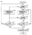
- FIG. 16 is a flowchart of processing executed in the beverage manufacturing apparatus 1 for countdown and resetting of the mill grinding suppression timer. The process of FIG. 16 is started on the condition that the “milling suppression timer” is set in step S50 of FIG. 15, and is executed in parallel with the process of FIG.
- step S100 CPU 901 determines whether or not the supply of power from the external power source to beverage manufacturing apparatus 1 is stopped. If the CPU 901 determines that it has stopped, the control proceeds to step S110, and if it determines that it has not stopped, the control proceeds to step S140.
- step S110 the CPU 901 receives power from the auxiliary power source 910 and counts down the mill grinding suppression timer. Then, the control proceeds to step S120.
- step S120 the CPU 901 determines whether or not the supply of power to the beverage production apparatus 1 by the external power source has been resumed. If the CPU 901 determines that the process has been resumed, the CPU 901 advances the control to step S150. On the other hand, if CPU 901 determines that it has not been restarted, it proceeds to step S130.
- step S130 the CPU 901 determines whether the count of the mill grinding suppression timer has ended. If it is determined that the process has been completed, the control proceeds to step S160. If it is determined that the process has not been completed, the control is returned to step S110.
- step S140 the CPU 901 receives power from an external power source and counts down the mill grinding suppression timer. Then, the control proceeds to step S150.
- step S150 the CPU 901 determines whether the count of the mill grinding suppression timer has ended. If it is determined that the process has been completed, the control proceeds to step S160. If it is determined that the process has not been completed, the control is returned to step S100.
- step S160 the CPU 901 clears the mill grinding suppression timer and ends the process.
- step S10 the grinding operation by the grinding motor unit 120 is executed in step S30.
- the CPU 901 continues to count down the mill grind suppression timer upon receipt of power from the auxiliary power source 910 even if the power supply from the external power supply is stopped due to the power outlet of the beverage production apparatus 1 being unplugged or the like. .
- the countdown of the mill grinding suppression timer is interrupted by stopping the supply of power from the external power supply, and before the count of the mill grinding suppression timer is terminated by stopping the power supply from the external power supply. It is possible to avoid that the timer is cleared (the setting data indicating that the timer has been set is deleted). Therefore, the milling operation can be reliably suppressed for the time measured by the milling suppression timer or longer.
- the hardware configuration of the beverage production apparatus according to the second embodiment can be the same as that of the beverage production apparatus 1 according to the first embodiment.
- the beverage production apparatus 1 according to the second embodiment has information (correction information) for correcting the clock by the internal clock 910A with the clock by the external clock 904.
- the CPU 901 receives power from the auxiliary power source 910 and counts down the mill grinding suppression timer in the process described with reference to FIG. 16, the clock by the internal clock 910A is used as the correction information. The above countdown is executed while correcting.
- FIG. 17 is a diagram schematically showing clocks by three types of clock oscillation circuits.
- “external clock” indicates an example of a clock oscillated by the external clock 904.
- “Internal clock (1)” and “Internal clock (2)” indicate two examples of clocks oscillated by a clock oscillation circuit that can be used as the internal clock 910A.
- a relatively accurate clock oscillation circuit is used as the external clock 904, while a low-accuracy clock oscillation circuit is used as the internal clock 910A.
- the clock oscillated by the internal clock 910A has a large variation among individuals.
- the clock difference between “internal clock (1)” and “internal clock (2)” in FIG. 17 corresponds to variations in the clock oscillated by the clock oscillation circuit used as internal clock 910A.
- the auxiliary power source 910 as described with reference to FIG. 16 is used, and the internal clock 910A is used.
- the external power supply is used and the countdown is completed after the milling suppression timer is set as compared to the case where the countdown is performed using the external clock 904. There may be differences in the time.
- the CPU 901 generates the correction information using the ratio of the oscillation period of the internal clock 910A and the external clock 904 in the beverage manufacturing apparatus 1 or the like.
- the CPU 901 uses the auxiliary power source 910 and counts down the mill grinding suppression timer using the internal clock 910A, the CPU 901 executes the countdown while correcting the clock of the internal clock 910A using the correction information. .
- finished after a mill grinding suppression timer is set can be reduced.
- the hardware configuration of the beverage production apparatus according to the third embodiment can be the same as that of the beverage production apparatus 1 according to the first embodiment.
- the time measured by the mill grind suppression timer that is, the length of time required from the setting of the timer to the countdown is the number of beverage cups set for the mill grind.
- the CPU 901 selects a timer to be set so that the time measured by the mill grind suppression timer becomes longer.
- the period during which the grinding operation is not performed as the rise in temperature is assumed to be higher by adjusting the time measured by the milling suppression timer as described above. Can be lengthened.
- the measurement time by the milling suppression timer is set according to the time of the grinding operation performed in the production of one beverage, instead of the number of cups instructed in the production of one beverage, Good.
- the time measured by the milling suppression timer is twice the time of the grinding operation. Specifically, if the milling operation is performed for 2 minutes, then the measurement time of the milling suppression timer is set to 4 minutes, and the milling operation is suppressed for 4 minutes.
- the hardware configuration of the beverage production apparatus according to the fourth embodiment can be the same as that of the beverage production apparatus 1 according to the first embodiment.
- the beverage production apparatus 1 according to the fourth embodiment does not set the mill grinding suppression timer in some cases even when the mill grinding operation is performed.
- the CPU 901 of the beverage manufacturing apparatus 1 according to the fourth embodiment sets a milling suppression timer based on the history of execution of the milling operation as well as the end of one milling operation. Decide if you want to.
- the CPU 901 sets a mill grinding suppression timer on condition that a specific condition is satisfied in, for example, step S50 (see FIG. 15).
- the specific condition is, for example, that the milling operation is continuously performed at intervals of a predetermined time (for example, 15 minutes) or less, and the integrated value of the period of such continuous milling operation is a specific time (for example, 30 Minutes).
- Whether or not to set the milling suppression timer is determined based on the history of milling operation (substantially the length of time during which the milling operation has been continued) as executed in the fourth embodiment. Accordingly, the milling operation can be suppressed only when the lower mill 350 and the upper mill 360 need to be cooled. Thereby, the beverage manufacturing apparatus 1 can avoid the situation where a mill grinding operation cannot be performed for cooling of the lower mill 350 and the upper mill 360 as much as possible when the user desires to perform the mill grinding operation.
- the hardware configuration of the beverage manufacturing apparatus of the fifth embodiment can be the same as that of the beverage manufacturing apparatus 1 of the first embodiment.
- the milling operation is not executed during the period when the milling suppression timer is set, but the relative rotational speed of the lower mill 350 and the upper mill 360 is reduced. Then, the milling operation is executed. Thereby, the beverage manufacturing apparatus 1 can avoid the situation where a mill grinding operation cannot be performed as much as possible when a user desires to perform a mill grinding operation.
- the hardware configuration of the beverage manufacturing apparatus of the sixth embodiment can be the same as that of the beverage manufacturing apparatus 1 of the first embodiment.
- the temperature in the vicinity of the lower die 350 and / or the upper die 360 is measured.
- the beverage manufacturing apparatus 1 when the measured temperature exceeds a specific temperature, the beverage manufacturing apparatus 1 according to the sixth embodiment performs a milling operation until the measured temperature is equal to or lower than the specific temperature. Suppress.
- the “inhibition” may be prohibition of the milling operation, or may be a reduction in the relative rotational speed between the lower mill 350 and the upper mill 360 in the milling operation.
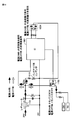
- FIG. 18 is a diagram illustrating a specific example of the configuration of the CPU 901 and the external clock 904 and their peripheral devices in the control device 111 (see FIG. 14).
- an IC (Integrated Circuit) 1001 is shown as a specific example of the CPU 901.
- a clock oscillation circuit 1004 is shown as a specific example of the external clock 904.
- a capacitor 1010 is shown as a specific example of the auxiliary power source 910.
- the current flow during the period when the beverage production apparatus 1 is supplied with electric power from the external power source is indicated by a thick arrow.
- the flow of current during the period when the supply of power from the external power source to the beverage production apparatus 1 is stopped is indicated by a white arrow.
- the voltage of 24 V of the external power source is stepped down to 5 V by regulator 1101 and supplied to IC 1001.
- the IC 1001 supplies power to the clock oscillation circuit 1004.
- the IC 1001 turns on the transistor 1102 (makes it conductive)
- power from the external power supply is supplied to various components such as a switch (SW) and a thermistor (TH) through the transistor 1102. Further, the capacitor 1010 is charged with power from the external power source.
- SW switch
- TH thermistor
- the IC 1001 does not supply power to the clock oscillation circuit 1004, and the clock oscillation circuit in the IC 1001 is used with the power accumulated in the capacitor 1010. Drive to execute the count operation of the mill grinding suppression timer. Further, the IC 1001 turns off the transistor 1102 (non-conducting state) so that power is not supplied to various components such as the switch (SW) and the thermistor (TH).
- the time of “15 minutes” is exemplified as the upper limit of the rotational speed of the die. For this reason, a count operation of at least “30 minutes” is required as the upper limit of the count operation of the mill grinding suppression timer.
- the auxiliary power supply (capacitor 1010) has at least a capacity necessary for turning off the transistor 1102 and driving only the IC 1001 (CPU 901) for 30 minutes. In order to drive the IC 1001 (CPU 901) for 30 minutes, a certain amount of capacity is required. For this reason, in the above embodiment, an electric double layer capacitor (referred to as a supercapacitor) having a relatively large capacity can be adopted as an example of the capacitor 1010.
Landscapes
- Engineering & Computer Science (AREA)
- Food Science & Technology (AREA)
- Life Sciences & Earth Sciences (AREA)
- Chemical & Material Sciences (AREA)
- Polymers & Plastics (AREA)
- Mechanical Engineering (AREA)
- Apparatus For Making Beverages (AREA)
- Food-Manufacturing Devices (AREA)
- Crushing And Grinding (AREA)
- Grinding And Polishing Of Tertiary Curved Surfaces And Surfaces With Complex Shapes (AREA)
Abstract
Description
好ましくは、制御部は、外部電源から電力を供給されるように構成されており、電動粉挽き機は、外部電源からの電力供給が遮断されたときに制御部へ電力を供給するための内部電源をさらに備え、制御部は、外部電源からの電力供給が遮断されたときに、内部電源から供給される電力を用いて粉砕制御モードを実行するように構成されている。
第1の実施の形態では、一例として、粉砕対象物として茶葉を用い、飲料としてお茶を製造する場合について説明するが、粉砕対象物は茶葉に限定されることなく、穀物、乾物、その他の粉砕対象物を用いて、飲料を製造する場合にも適用することが可能である。
図1から図3を参照して、第1の実施の形態における飲料製造装置1について説明する。図1は、飲料製造装置1の全体斜視図である。図2は、図1中II-II線矢視断面図である。図3は、飲料製造装置1の概略構成要素を示す全体斜視図である。
粉挽きユニット300は、装置本体100の前面側に設けられた粉挽きユニット装着領域180に対して、着脱可能に装着される。粉挽きユニット装着領域180には、粉挽駆動力連結機構130が前方に突出するように設けられ、この粉挽駆動力連結機構130に粉挽きユニット300が着脱可能に装着される。粉挽きユニット300は、粉挽駆動力連結機構130に連結されることにより、粉砕対象物である茶葉を挽くための駆動力を得る。
撹拌ユニット500は、装置本体100の前面側に設けられた撹拌ユニット装着領域190に対して、着脱可能に装着される。撹拌ユニット装着領域190には、撹拌モータ非接触テーブル140Aが設けられおり、撹拌ユニット500の内部に設けられた撹拌羽根550(後述の図13参照)を磁力を用いて回転駆動する。
次に、図4から図6を参照して、上記飲料製造装置1を用いた日本茶(飲料)の製造フローについて説明する。図4から図6は、飲料製造装置1を用いた日本茶吐出を示す第1から第3の製造フローを示す図である。なお、粉挽きユニット300には、所定量の日本茶葉が投入され、水タンク700には所定量の水が蓄えられている。
図4を参照して、第1製造フローについて説明する。この第1製造フローは、粉挽きユニット300における茶葉の粉砕と、装置本体100から撹拌ユニット500への給湯が並行して行なわれるフローである。
図5を参照して、第2製造フローについて説明する。この第2製造フローは、粉挽きユニット300における茶葉が粉砕された後に、装置本体100から撹拌ユニット500への給湯が行なわれるフローである。
図6を参照して、第3製造フローについて説明する。この第3製造フローは、撹拌ユニット500においてお湯を撹拌により冷却するステップを備えている。
次に、図7を参照して、飲料製造装置1の内部構造について説明する。図7は、飲料製造装置1の内部構造のみを示す斜視図である。飲料製造装置1の装置本体100の内部においては、水タンク700の前面側には、電子部品が搭載されたプリント配線基板を用いた制御ユニット110が配置されている。利用者によるスタート信号の入力に基づき、上記お茶の製造フローが、制御ユニット110により実行される。
次に、図9から図11を参照して、粉挽きユニット300の構造について説明する。図9は、粉挽きユニット300の斜視図である。図10は、粉挽きユニット300の分解斜視図である。図11は、粉挽きユニット300の縦断面図である。
次に、図12および図13を参照して、撹拌ユニット500の構造について説明する。図12は、撹拌ユニット500の斜視図である。図13は、撹拌ユニット500の縦断面図である。
図14は、第1の実施の形態の飲料製造装置1のハードウェア構成の一例を示す図である。図14に示されるように、飲料製造装置1は、当該飲料製造装置1の動作を制御するための制御装置111を含む。第1の実施の形態の飲料製造装置1では、制御装置111は、制御ユニット110(図7参照)内に位置する。ただし、制御装置111の配置は、これに限定されない。
次に、飲料製造装置1における、茶葉の粉砕および撹拌ユニット500への給湯を含む、飲料の製造についての、具体的な制御フローについて説明する。図15は、飲料の製造のために飲料製造装置1において実行される処理の一例のフローチャートである。
次に、ミル挽き抑制タイマのカウントダウンおよびリセットのための処理について説明する。図16は、ミル挽き抑制タイマのカウントダウンおよびリセットのために飲料製造装置1において実行される処理のフローチャートである。図16の処理は、図15のステップS50で「ミル挽き抑制タイマ」がセットされたことを条件として開始され、図15の処理と並行して実行される。
第2の実施の形態の飲料製造装置のハードウェア構成は、第1の実施の形態の飲料製造装置1と同様とすることができる。第2の実施の形態の飲料製造装置1は、内部クロック910Aによるクロックを外部クロック904によるクロックで補正するための情報(補正用情報)を有している。そして、CPU901は、図16を参照して説明されたような処理において補助電源910から電力の供給を受けてミル挽き抑制タイマのカウントダウンを行う場合、内部クロック910Aによるクロックを上記補正用情報を用いて補正しながら、上記カウントダウンを実行する。
第3の実施の形態の飲料製造装置のハードウェア構成は、第1の実施の形態の飲料製造装置1と同様とすることができる。第3の実施の形態の飲料製造装置1は、ミル挽き抑制タイマによって計測される時間、つまり、当該タイマのセットからカウントダウンまでに要する時間の長さが、ミル挽きについてセットされる飲料の杯数に従って変更される。たとえば、飲料製造装置1において、1回の飲料の製造の指示において、1~3杯の飲料の製造の指示が可能である場合、1杯の飲料の製造が指示されたときよりも2杯の飲料の製造が指示されたときの方が、CPU901は、ミル挽き抑制タイマによって計測される時間が長くなるように、セットするタイマを選択する。
第4の実施の形態の飲料製造装置のハードウェア構成は、第1の実施の形態の飲料製造装置1と同様とすることができる。第4の実施の形態の飲料製造装置1は、ミル挽き動作が行なわれても、場合によってはミル挽き抑制タイマをセットしない。より具体的には、第4の実施の形態の飲料製造装置1のCPU901は、1回のミル挽き動作の終了だけでなく、ミル挽き動作の実行の履歴に基づいて、ミル挽き抑制タイマをセットするかどうかを決定する。
第5の実施の形態の飲料製造装置のハードウェア構成は、第1の実施の形態の飲料製造装置1と同様とすることができる。第5の実施の形態の飲料製造装置1では、ミル挽き抑制タイマがセットされている期間中、ミル挽き動作が実行されないのではなく、下臼350と上臼360の相対的な回転数が低減されて、ミル挽き動作が実行される。これにより、飲料製造装置1は、ユーザがミル挽き動作を実行させることを希望したときに、ミル挽き動作が実行できないという事態を極力回避し得る。
第6の実施の形態の飲料製造装置のハードウェア構成は、第1の実施の形態の飲料製造装置1と同様とすることができる。第6の実施の形態の飲料製造装置1では、ミル挽き抑制タイマを利用する代わりに、下臼350および/または上臼360近傍の温度が計測される。
図18は、制御装置111(図14参照)におけるCPU901および外部クロック904、ならびに、これらの周辺機器の構成の具体例を示す図である。図18に示された具体例では、CPU901の具体例としてIC(Integrated Circuit)1001が示されている。また、外部クロック904の具体例として、クロック発振回路1004が示されている。また、補助電源910の具体例として、コンデンサ1010が示されている。
Claims (5)
- 食品を粉砕するための電動粉挽き装置であって、
互いに当接した2以上の部材を相対的に移動させて食品を粉砕し、当該食品の粉末を生成するための粉砕機構と、
前記粉砕機構の動作を制御するように構成された制御部とを備え、
前記制御部は、
前記粉砕機構の前記食品の粉砕の後、前記粉砕機構による食品の粉砕の動作を抑制するための粉砕抑制モードに遷移して、所定の条件が満たされるまで当該粉砕機構による粉砕の動作を抑制するための処理を実行するように構成されている、電動粉挽き機。 - 前記所定の条件とは、所定時間の経過である、請求項1に記載の電動粉挽き機。
- 前記制御部は、外部電源から電力を供給されるように構成されており、
前記電動粉挽き機は、外部電源からの電力供給が遮断されたときに前記制御部へ電力を供給するための内部電源をさらに備え、
前記制御部は、前記外部電源からの電力供給が遮断されたときに、前記内部電源から供給される電力を用いて前記粉砕制御モードを実行するように構成されている、請求項1または請求項2に記載の電動粉挽き機。 - 前記制御部は、前記粉砕機構による食品の粉砕の態様に基づいて、前記所定の条件を設定するように構成されている、請求項1~請求項3のいずれか1項に記載の電動粉挽き機。
- 前記外部電源から電力を供給されてクロックを発振するための第1の発振回路と、
前記内部電源から電力を供給されてクロックを発振するための第2の発振回路と、
前記第1の発振回路のクロックに基づいて、前記第2の発振回路のクロックを補正するための情報を格納するための記憶手段とをさらに備え、
前記制御部は、前記内部電源から電力を供給されて前記処理を実行する場合に、前記第2の発振回路が発信するクロックを前記情報を利用して補正して利用するように構成されている、請求項1~請求項4のいずれか1項に記載の電動粉挽き機。
Priority Applications (4)
| Application Number | Priority Date | Filing Date | Title |
|---|---|---|---|
| CA2939068A CA2939068A1 (en) | 2014-04-24 | 2015-04-22 | Electric milling machine |
| CN201580008419.4A CN105980061B (zh) | 2014-04-24 | 2015-04-22 | 电动磨粉机 |
| US15/119,766 US20170049263A1 (en) | 2014-04-24 | 2015-04-22 | Electric milling machine |
| RU2016135247A RU2660669C2 (ru) | 2014-04-24 | 2015-04-22 | Электрическая размалывающая машина |
Applications Claiming Priority (2)
| Application Number | Priority Date | Filing Date | Title |
|---|---|---|---|
| JP2014090310A JP6358840B2 (ja) | 2014-04-24 | 2014-04-24 | 電動粉挽き機 |
| JP2014-090310 | 2014-04-24 |
Publications (1)
| Publication Number | Publication Date |
|---|---|
| WO2015163359A1 true WO2015163359A1 (ja) | 2015-10-29 |
Family
ID=54332522
Family Applications (1)
| Application Number | Title | Priority Date | Filing Date |
|---|---|---|---|
| PCT/JP2015/062217 Ceased WO2015163359A1 (ja) | 2014-04-24 | 2015-04-22 | 電動粉挽き機 |
Country Status (6)
| Country | Link |
|---|---|
| US (1) | US20170049263A1 (ja) |
| JP (1) | JP6358840B2 (ja) |
| CN (1) | CN105980061B (ja) |
| CA (1) | CA2939068A1 (ja) |
| RU (1) | RU2660669C2 (ja) |
| WO (1) | WO2015163359A1 (ja) |
Families Citing this family (3)
| Publication number | Priority date | Publication date | Assignee | Title |
|---|---|---|---|---|
| CN107321438A (zh) * | 2017-07-14 | 2017-11-07 | 宾信国际有限公司 | 电动磨茶机 |
| CN207791202U (zh) * | 2017-07-28 | 2018-08-31 | 遨想科创有限公司 | 一种自动磨粉咖啡胶囊制造机 |
| JP7166674B1 (ja) * | 2021-11-16 | 2022-11-08 | 株式会社大都技研 | コーヒーマシン |
Citations (6)
| Publication number | Priority date | Publication date | Assignee | Title |
|---|---|---|---|---|
| JPS62246325A (ja) * | 1986-04-18 | 1987-10-27 | 松下電器産業株式会社 | コ−ヒ−沸し器 |
| JP2000000478A (ja) * | 1998-06-16 | 2000-01-07 | Nippon Kouatsu Electric Co | 粉砕機 |
| JP3776795B2 (ja) * | 2001-12-21 | 2006-05-17 | 日本航空電子工業株式会社 | 慣性装置 |
| JP4241067B2 (ja) * | 2003-01-31 | 2009-03-18 | キヤノン株式会社 | インクジェット記録装置及びその制御方法 |
| JP2010074211A (ja) * | 2008-09-16 | 2010-04-02 | Nec Commun Syst Ltd | クロック同期回路、電子制御ユニット、車載ネットワークシステム及びクロック同期方法 |
| JP2012037275A (ja) * | 2010-08-04 | 2012-02-23 | Yokogawa Electric Corp | 内圧防爆型測定機器 |
Family Cites Families (41)
| Publication number | Priority date | Publication date | Assignee | Title |
|---|---|---|---|---|
| US3483464A (en) * | 1967-08-10 | 1969-12-09 | Bell Telephone Labor Inc | Voltage regulator systems employing a multifunctional circuit comprising a field effect transistor constant current source |
| US4259639A (en) * | 1978-11-03 | 1981-03-31 | Vitatron Medical B.V. | Circuit and method for detecting battery source end of life |
| US4491772A (en) * | 1983-06-09 | 1985-01-01 | General Electric Company | Control circuit for an electronically commutated motor (ECM), method of timing the electronic commutation of an ECM, and method of operating an ECM |
| JPS6066504A (ja) * | 1983-09-22 | 1985-04-16 | Oki Electric Ind Co Ltd | 半導体集積回路 |
| US4698530A (en) * | 1984-11-09 | 1987-10-06 | National Semiconductor Corporation | Power switch for dual power supply circuit |
| JPS61191973A (ja) * | 1985-02-20 | 1986-08-26 | Fujitsu Ltd | 試験回路をそなえた半導体集積回路 |
| US4855613A (en) * | 1987-05-08 | 1989-08-08 | Mitsubishi Denki Kabushiki Kaisha | Wafer scale integration semiconductor device having improved chip power-supply connection arrangement |
| US4795883A (en) * | 1987-07-08 | 1989-01-03 | Environmental Fragrance Technologies, Ltd. | Aroma generating apparatus and driver circuit |
| JPH0179420U (ja) * | 1987-11-19 | 1989-05-29 | ||
| US4871982A (en) * | 1988-10-28 | 1989-10-03 | Dallas Semiconductor Corporation | Low-voltage oscillator with separate startup mode |
| US4912435A (en) * | 1988-10-28 | 1990-03-27 | Dallas Semiconductor Corporation | Low-voltage oscillator with separate startup mode |
| US5150079A (en) * | 1990-03-27 | 1992-09-22 | Dallas Semiconductor Corporation | Two-mode oscillator |
| US5619066A (en) * | 1990-05-15 | 1997-04-08 | Dallas Semiconductor Corporation | Memory for an electronic token |
| US5111069A (en) * | 1990-08-27 | 1992-05-05 | Dallas Semiconductor Corporation | Layout of integrated circuit with very large transistors |
| US5442146A (en) * | 1992-04-03 | 1995-08-15 | Weigh-Tronix, Inc. | Counting scale and load cell assembly therefor |
| US5805923A (en) * | 1995-05-26 | 1998-09-08 | Sony Corporation | Configurable power management system having a clock stabilization filter that can be enabled or bypassed depending upon whether a crystal or can oscillator is used |
| UA27007C2 (uk) * | 1995-07-18 | 2000-02-28 | Український науково-дослідний інститут електропобутових машин "Веста" | Уhіверсальhа кухоhhа машиhа стаціоhарhого типу |
| US5752047A (en) * | 1995-08-11 | 1998-05-12 | Mcdonnell Douglas Corporation | Modular solid state power controller with microcontroller |
| JP3346999B2 (ja) * | 1996-01-08 | 2002-11-18 | 株式会社東芝 | 入出力装置 |
| US6208542B1 (en) * | 1998-06-30 | 2001-03-27 | Sandisk Corporation | Techniques for storing digital data in an analog or multilevel memory |
| US6160428A (en) * | 1998-12-10 | 2000-12-12 | National Semiconductor Corporation | Universal on-chip initialization circuit |
| JP2002000470A (ja) * | 2000-06-23 | 2002-01-08 | Matsushita Refrig Co Ltd | 食品製造装置及び食品製造方法 |
| US6580332B2 (en) * | 2000-11-30 | 2003-06-17 | Cts Corporation | Dual-function connection pads for TCXO integrated circuit |
| JP4498633B2 (ja) * | 2001-04-06 | 2010-07-07 | 富士通マイクロエレクトロニクス株式会社 | オシレータ回路、及び内部電源生成回路 |
| JP4582962B2 (ja) * | 2001-06-08 | 2010-11-17 | 富士通セミコンダクター株式会社 | 電源網解析方法、電源網解析方法を実行するコンピュータプログラム、記録媒体、及び電源網解析装置 |
| US20030007442A1 (en) * | 2001-07-09 | 2003-01-09 | Henrichs Joseph Reid | Light intensity modulated direct overwrite magneto-optical microhead array chip hard disk drive |
| JP2003022686A (ja) * | 2001-07-09 | 2003-01-24 | Mitsubishi Electric Corp | 半導体集積回路装置 |
| US20030167345A1 (en) * | 2002-02-25 | 2003-09-04 | Knight Alexander N. | Communications bridge between a vehicle information network and a remote system |
| JP4282412B2 (ja) * | 2003-09-02 | 2009-06-24 | 株式会社東芝 | 電流源回路 |
| JP2005122574A (ja) * | 2003-10-17 | 2005-05-12 | Renesas Technology Corp | 半導体集積回路 |
| US7296170B1 (en) * | 2004-01-23 | 2007-11-13 | Zilog, Inc. | Clock controller with clock source fail-safe logic |
| DE102004015057A1 (de) * | 2004-03-25 | 2005-10-20 | Siemens Ag | Verfahren, Steuervorrichtung und Antriebsvorrichtung zum Lösen einer festgeklebten Ladung von der Innenwand eines Mahlrohrs |
| JP2006039830A (ja) * | 2004-07-26 | 2006-02-09 | Renesas Technology Corp | 半導体集積回路 |
| US7414372B2 (en) * | 2005-10-24 | 2008-08-19 | International Rectifier Corporation | Dimming ballast control circuit |
| JP2008109243A (ja) * | 2006-10-24 | 2008-05-08 | Renesas Technology Corp | Rf通信用半導体集積回路 |
| US20080307240A1 (en) * | 2007-06-08 | 2008-12-11 | Texas Instruments Incorporated | Power management electronic circuits, systems, and methods and processes of manufacture |
| KR100904467B1 (ko) * | 2008-01-09 | 2009-06-24 | 주식회사 하이닉스반도체 | 펌핑전압 감지회로 |
| US8777138B2 (en) * | 2009-01-18 | 2014-07-15 | Techtronic Floor Care Technology Limited | Overload fault condition detection system for article destruction device |
| SE0900572L (sv) * | 2009-04-29 | 2010-02-23 | Anders Karlstroem | Förfarande för att begränsa processbetingelser i raffinörer för att förhindra fiberklippning och haveri av malsegment |
| GB0919331D0 (en) * | 2009-11-04 | 2009-12-23 | Strix Ltd | Cordless electrical appliances |
| CN103736551B (zh) * | 2013-11-11 | 2016-01-13 | 文树雄 | 一种改进的自动磨浆机 |
-
2014
- 2014-04-24 JP JP2014090310A patent/JP6358840B2/ja active Active
-
2015
- 2015-04-22 US US15/119,766 patent/US20170049263A1/en not_active Abandoned
- 2015-04-22 CN CN201580008419.4A patent/CN105980061B/zh active Active
- 2015-04-22 CA CA2939068A patent/CA2939068A1/en not_active Abandoned
- 2015-04-22 WO PCT/JP2015/062217 patent/WO2015163359A1/ja not_active Ceased
- 2015-04-22 RU RU2016135247A patent/RU2660669C2/ru active
Patent Citations (6)
| Publication number | Priority date | Publication date | Assignee | Title |
|---|---|---|---|---|
| JPS62246325A (ja) * | 1986-04-18 | 1987-10-27 | 松下電器産業株式会社 | コ−ヒ−沸し器 |
| JP2000000478A (ja) * | 1998-06-16 | 2000-01-07 | Nippon Kouatsu Electric Co | 粉砕機 |
| JP3776795B2 (ja) * | 2001-12-21 | 2006-05-17 | 日本航空電子工業株式会社 | 慣性装置 |
| JP4241067B2 (ja) * | 2003-01-31 | 2009-03-18 | キヤノン株式会社 | インクジェット記録装置及びその制御方法 |
| JP2010074211A (ja) * | 2008-09-16 | 2010-04-02 | Nec Commun Syst Ltd | クロック同期回路、電子制御ユニット、車載ネットワークシステム及びクロック同期方法 |
| JP2012037275A (ja) * | 2010-08-04 | 2012-02-23 | Yokogawa Electric Corp | 内圧防爆型測定機器 |
Also Published As
| Publication number | Publication date |
|---|---|
| RU2660669C2 (ru) | 2018-07-09 |
| US20170049263A1 (en) | 2017-02-23 |
| JP2015208394A (ja) | 2015-11-24 |
| RU2016135247A (ru) | 2018-05-24 |
| CN105980061B (zh) | 2019-05-14 |
| RU2016135247A3 (ja) | 2018-05-24 |
| JP6358840B2 (ja) | 2018-07-18 |
| CA2939068A1 (en) | 2015-10-29 |
| CN105980061A (zh) | 2016-09-28 |
Similar Documents
| Publication | Publication Date | Title |
|---|---|---|
| CA2931062C (en) | Beverage preparation apparatus | |
| CN113395924A (zh) | 便携式可充电搅拌器 | |
| JP6358840B2 (ja) | 電動粉挽き機 | |
| JP6011184B2 (ja) | 飲料供給装置 | |
| EP3141170A1 (en) | Blender heatable by high frequency induction heating | |
| CA2930643C (en) | Beverage preparation apparatus | |
| JP2015208395A (ja) | 飲料製造装置 | |
| JP2017030828A (ja) | 飲料ディスペンサ | |
| WO2016143406A1 (ja) | 飲料製造装置 | |
| CN106068081A (zh) | 制造豆浆的方法和设备 | |
| KR20230083501A (ko) | 커피 메이커 및 이의 제어 방법 | |
| CA2928025C (en) | Beverage preparation apparatus | |
| JP2008272143A (ja) | 炊飯器 | |
| CN203898067U (zh) | 豆浆机 | |
| JP5598195B2 (ja) | カップ式飲料自動販売機等の飲料調合装置 | |
| CN107080474A (zh) | 破壁机和破壁机的控制方法 | |
| JP6376910B2 (ja) | 飲料製造装置 | |
| JP2014073290A (ja) | 自動製パン機 | |
| JP2016140803A (ja) | 粉砕装置及び飲料製造装置 | |
| CN107811512A (zh) | 用磨豆咖啡机制作咖啡的方法和磨豆咖啡机 | |
| CN105212738B (zh) | 豆浆机 | |
| JPH10162235A (ja) | 自動販売機のピークシフト制御装置 | |
| JP6131694B2 (ja) | カップ式飲料自動販売機 | |
| CN118662016A (zh) | 称重装置、出料装置及出料控制系统 | |
| JP2014090898A (ja) | 自動製パン器 |
Legal Events
| Date | Code | Title | Description |
|---|---|---|---|
| 121 | Ep: the epo has been informed by wipo that ep was designated in this application |
Ref document number: 15783364 Country of ref document: EP Kind code of ref document: A1 |
|
| ENP | Entry into the national phase |
Ref document number: 2939068 Country of ref document: CA |
|
| WWE | Wipo information: entry into national phase |
Ref document number: 15119766 Country of ref document: US |
|
| WWE | Wipo information: entry into national phase |
Ref document number: IDP00201605650 Country of ref document: ID |
|
| NENP | Non-entry into the national phase |
Ref country code: DE |
|
| ENP | Entry into the national phase |
Ref document number: 2016135247 Country of ref document: RU Kind code of ref document: A |
|
| 122 | Ep: pct application non-entry in european phase |
Ref document number: 15783364 Country of ref document: EP Kind code of ref document: A1 |