WO2015141631A1 - バッテリセルの加圧装置 - Google Patents
バッテリセルの加圧装置 Download PDFInfo
- Publication number
- WO2015141631A1 WO2015141631A1 PCT/JP2015/057715 JP2015057715W WO2015141631A1 WO 2015141631 A1 WO2015141631 A1 WO 2015141631A1 JP 2015057715 W JP2015057715 W JP 2015057715W WO 2015141631 A1 WO2015141631 A1 WO 2015141631A1
- Authority
- WO
- WIPO (PCT)
- Prior art keywords
- battery cell
- spacers
- thickness direction
- spacer
- housing
- Prior art date
Links
Images


Classifications
-
- H—ELECTRICITY
- H01—ELECTRIC ELEMENTS
- H01M—PROCESSES OR MEANS, e.g. BATTERIES, FOR THE DIRECT CONVERSION OF CHEMICAL ENERGY INTO ELECTRICAL ENERGY
- H01M10/00—Secondary cells; Manufacture thereof
- H01M10/04—Construction or manufacture in general
- H01M10/0481—Compression means other than compression means for stacks of electrodes and separators
-
- H—ELECTRICITY
- H01—ELECTRIC ELEMENTS
- H01M—PROCESSES OR MEANS, e.g. BATTERIES, FOR THE DIRECT CONVERSION OF CHEMICAL ENERGY INTO ELECTRICAL ENERGY
- H01M50/00—Constructional details or processes of manufacture of the non-active parts of electrochemical cells other than fuel cells, e.g. hybrid cells
- H01M50/20—Mountings; Secondary casings or frames; Racks, modules or packs; Suspension devices; Shock absorbers; Transport or carrying devices; Holders
- H01M50/204—Racks, modules or packs for multiple batteries or multiple cells
- H01M50/207—Racks, modules or packs for multiple batteries or multiple cells characterised by their shape
- H01M50/211—Racks, modules or packs for multiple batteries or multiple cells characterised by their shape adapted for pouch cells
-
- H—ELECTRICITY
- H01—ELECTRIC ELEMENTS
- H01M—PROCESSES OR MEANS, e.g. BATTERIES, FOR THE DIRECT CONVERSION OF CHEMICAL ENERGY INTO ELECTRICAL ENERGY
- H01M50/00—Constructional details or processes of manufacture of the non-active parts of electrochemical cells other than fuel cells, e.g. hybrid cells
- H01M50/20—Mountings; Secondary casings or frames; Racks, modules or packs; Suspension devices; Shock absorbers; Transport or carrying devices; Holders
- H01M50/289—Mountings; Secondary casings or frames; Racks, modules or packs; Suspension devices; Shock absorbers; Transport or carrying devices; Holders characterised by spacing elements or positioning means within frames, racks or packs
- H01M50/291—Mountings; Secondary casings or frames; Racks, modules or packs; Suspension devices; Shock absorbers; Transport or carrying devices; Holders characterised by spacing elements or positioning means within frames, racks or packs characterised by their shape
-
- H—ELECTRICITY
- H01—ELECTRIC ELEMENTS
- H01M—PROCESSES OR MEANS, e.g. BATTERIES, FOR THE DIRECT CONVERSION OF CHEMICAL ENERGY INTO ELECTRICAL ENERGY
- H01M2220/00—Batteries for particular applications
- H01M2220/20—Batteries in motive systems, e.g. vehicle, ship, plane
-
- Y—GENERAL TAGGING OF NEW TECHNOLOGICAL DEVELOPMENTS; GENERAL TAGGING OF CROSS-SECTIONAL TECHNOLOGIES SPANNING OVER SEVERAL SECTIONS OF THE IPC; TECHNICAL SUBJECTS COVERED BY FORMER USPC CROSS-REFERENCE ART COLLECTIONS [XRACs] AND DIGESTS
- Y02—TECHNOLOGIES OR APPLICATIONS FOR MITIGATION OR ADAPTATION AGAINST CLIMATE CHANGE
- Y02E—REDUCTION OF GREENHOUSE GAS [GHG] EMISSIONS, RELATED TO ENERGY GENERATION, TRANSMISSION OR DISTRIBUTION
- Y02E60/00—Enabling technologies; Technologies with a potential or indirect contribution to GHG emissions mitigation
- Y02E60/10—Energy storage using batteries
-
- Y—GENERAL TAGGING OF NEW TECHNOLOGICAL DEVELOPMENTS; GENERAL TAGGING OF CROSS-SECTIONAL TECHNOLOGIES SPANNING OVER SEVERAL SECTIONS OF THE IPC; TECHNICAL SUBJECTS COVERED BY FORMER USPC CROSS-REFERENCE ART COLLECTIONS [XRACs] AND DIGESTS
- Y02—TECHNOLOGIES OR APPLICATIONS FOR MITIGATION OR ADAPTATION AGAINST CLIMATE CHANGE
- Y02P—CLIMATE CHANGE MITIGATION TECHNOLOGIES IN THE PRODUCTION OR PROCESSING OF GOODS
- Y02P70/00—Climate change mitigation technologies in the production process for final industrial or consumer products
- Y02P70/50—Manufacturing or production processes characterised by the final manufactured product
Definitions
- This invention relates to the improvement of the pressurization apparatus which pressurizes the battery cell which makes flat shape in the thickness direction.
- a battery cell used in an electric vehicle or a hybrid vehicle has, for example, a power generation element enclosed with an electrolyte inside an exterior body made of a laminate film, and has a thin flat shape in the thickness direction. Positive and negative terminals are derived from part of the section.
- a step of pressurizing the battery cell in a predetermined thickness direction is performed so that the electrolyte is satisfactorily permeated while discharging the gas inside the exterior body.
- Patent Document 1 discloses a technique for pressurizing a cell used for a liquid crystal panel.
- battery cells and fixed-width spacers are alternately arranged in the thickness direction in a pressurizing device (pressurizing magazine), and the entire number of these battery cells and spacers are thicker from both sides.
- a technique is known in which a plurality of cells are pressurized simultaneously by applying pressure in the vertical direction.
- interval of a some cell needs to be the same space
- the thickness of the battery cell is not one type because the capacity varies depending on the type of vehicle installed.
- the conventional pressurizing apparatus that pressurizes the whole of the plurality of battery cells and the spacers alternately arranged as described above from both sides, the interval between adjacent battery cells varies depending on the thickness of the battery cell.
- the overall dimensions in the pressurized state change. For this reason, the position of the charging / discharging device with respect to the chuck portion is displaced, and charging / discharging cannot be performed. Therefore, it is necessary to prepare different pressurizing devices for different types of battery cells with different thicknesses, and an additional magazine sorting area is required, which increases the manufacturing cost and the required area of the factory, and increases the productivity. There is a problem that decreases.
- the present invention provides a novel pressurizing apparatus that can handle a plurality of types of battery cells having different thicknesses. That is, the present invention provides a battery cell pressurization in which a power generation element is enclosed with an electrolyte inside an exterior body made of a laminate film, and a plurality of thin battery cells in the thickness direction are pressed in the thickness direction.
- a device that accommodates the plurality of battery cells, and a plurality of the battery cells that are arranged side by side in the thickness direction and are supported by the housing, and are expanded and contracted at least in the thickness direction according to the fluid pressure of the working fluid sealed inside.
- a plurality of spacers having a pouch shape and a pressure supply passage for supplying fluid from a fluid pressure source to the plurality of spacers.
- the battery cell is pressurized by inflating the spacers alternately arranged with the battery cell, so that the battery for the housing of the pressurizing device can be used regardless of the thickness of the target battery cell.
- the cell position (center position in the thickness direction) is obtained at the same position.
- the perspective view which shows the film-clad battery as a battery cell pressurized by the pressurization apparatus which concerns on one Example of this invention.
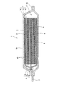
- Sectional drawing of the film-clad battery of FIG. The top view which shows the pressurization apparatus which concerns on 1st Example.
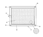
- the front view (A) and side view (B) which show the spacer of the said pressurization apparatus.
- Sectional drawing of the principal part along the BB line of FIG. 4 which shows the contraction state (A) and expansion
- wire of FIG. 3 which similarly shows the contraction state (A) and expansion state (B) of the said spacer.
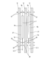
- FIG. 10 is a cross-sectional view taken along line CC of FIG. 9.
- Explanatory drawing in the contracted state seen from the upper surface shown in the state which combined the spacer provided with the cell support part with the thin battery cell.
- Explanatory drawing similarly in an expanded state.
- Explanatory drawing in the contracted state seen from the upper surface shown in the state which combined the spacer provided with the cell support part with the thick battery cell.
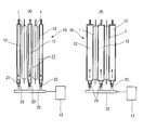
- the side view of the said pressurization apparatus Explanatory drawing when the effective length L of the housing of 2nd Example is set long. Explanatory drawing when the effective length L of the housing of 2nd Example is set short.
- This film-clad battery 1 is, for example, a lithium ion secondary battery, has a flat rectangular appearance, and has a pair of thin plate-like terminals 2 and 3 made of conductive metal foil at one end edge in the longitudinal direction. It has.
- This film-clad battery 1 is one in which a rectangular electrode laminate 4 is housed inside an outer package 5 made of a laminate film together with an electrolytic solution.
- the electrode laminate 4 that is a power generation element includes a plurality of positive plates 6 and negative plates 7 that are alternately laminated with separators 8 interposed therebetween.
- the plurality of positive electrode plates 6 are joined to the positive electrode terminal 2, and similarly, the plurality of negative electrode plates 7 are joined to the negative electrode terminal 3.
- the positive electrode plate 6 is obtained by coating a positive electrode active material layer 6b on both surfaces of a positive electrode current collector 6a made of a metal foil such as an aluminum foil.
- the negative electrode plate 7 is made of a negative electrode current collector made of a metal foil such as a copper foil.
- the negative electrode active material layer 7b is coated on both surfaces of the body 7a.
- the outer package 5 has a two-sheet structure of one laminate film disposed on the lower surface side of the electrode laminate 4 and another laminate film disposed on the upper surface side.
- the surrounding four sides are superposed and heat-sealed together along the periphery.
- the four peripheral edges 5a that are heat-sealed in this way form a thin sheet, whereas the central portion 5b that accommodates the electrode laminate 4 has a relatively large thickness.
- the pair of terminals 2 and 3 positioned on the short side of the rectangular film-clad battery 1 are drawn out through the bonding surface of the laminate film when the laminate film is heat-sealed.
- a pair of terminals 2 and 3 are arranged side by side on the same edge, but the positive terminal 2 is arranged on one edge and the negative terminal 3 is arranged on the other edge. It is also possible to do so.
- the manufacturing procedure of the film-clad battery 1 is as follows. First, in the lamination process, the positive electrode plate 6, the negative electrode plate 7 and the separator 8 are sequentially laminated, and the terminals 2 and 3 are attached by spot welding or the like to constitute the electrode laminate 4. Next, this electrode laminate 4 is covered with a laminate film to be the outer package 5, and the surrounding three sides are heat-sealed, leaving one side. Next, an electrolytic solution is injected and filled into the exterior body 5 through the open side, and then the open side is heat-sealed to seal the exterior body 5. Thereby, since the film-clad battery 1 is completed, it is shipped through processes such as charging, pressurization, aging, and voltage inspection described later.
- FIG. 3 and FIG. 4 show a first embodiment of the pressurizing device 10 which forms the main part of the present invention.
- the film-clad battery 1 is referred to as a battery cell 1.
- the pressurizing device 10 includes a housing 11 that houses a plurality of battery cells 1 and air as a working fluid that is fixed to the housing 11 at predetermined regular intervals with respect to the thickness direction P of the battery cells 1 and sealed inside. And a plurality of spacers 12 having a bag shape that can expand and contract in the thickness direction P according to the air pressure (fluid pressure).
- An air device 13 is provided outside the housing 11 as a fluid pressure source capable of adjusting the air pressure in the plurality of spacers 12.
- the housing 11 includes a base plate 14 that is a flat rectangular plate that serves as a friction surface to be conveyed by a conveyor, and a pair of fixed plates 15 that are erected at both longitudinal ends of the base plate 14.
- a plurality of spacers 12 are arranged at predetermined equal intervals between the pair of fixed plates 15.
- the fixed plate 15 receives the entire load when the plurality of battery cells 1 are pressurized, is thicker than the spacer 12, and is firmly fixed to the base plate 14.
- Guide shafts 16 spanned between the two fixing plates 15 are fixed to the four corners of the fixing plate 15, and the spacers 12 are supported by these guide shafts 16 so as to be slidable in the thickness direction P. Yes.
- a cylindrical bush 17 is inserted between the spacers 12 in the guide shaft 16 so that the pitch between the adjacent spacers 12 is constant. That is, the bushes 17 and the spacers 12 are alternately arranged on the guide shaft 16 so as to contact each other, and the whole is sandwiched between the fixing plates 15 on both sides.
- the plurality of spacers 12 are fixed at regular intervals between the pair of fixed plates 15. Note that the spacers 12 may be directly fixed to the housing 11 at regular intervals.
- an air pipe 22 extending in parallel with the guide shaft 16 is disposed as a pressure supply passage on the side of the housing 11, and the air pipe 22 extends from the air device 13 to each spacer 12 as will be described later.
- Air is supplied to the A check valve 29 for preventing a backflow of air introduced into the spacer 12 is provided at the proximal end of the air pipe 22, and the air is connected via a joint 30 detachably connected to the check valve 29.
- the pipe 22 is connected to the air device 13.
- the check valve 29 is opened by engaging a not-shown opening jig, and air can be released from the spacer 12.
- the spacer 12 has flat surfaces on both sides in the thickness direction, and these flat surfaces pressurize both sides of the battery cell 1 in the thickness direction P. 18 functions.
- the spacer 12 is made of a material that can be expanded and contracted in the thickness direction and that does not remain stretched even after repeated use.
- a rubber sheet containing cloth fibers at least in the portion of the pressure surface 18 is used as a material for the spacer 12.
- the spacer 12 has a bag-like shape into which air can be introduced.
- the two rubber sheets are joined to each other at the peripheral edge 19.
- Through holes 20 through which the guide shaft 16 is slidably inserted are formed.
- the peripheral edge portion 19 may be formed in a plate shape having rigidity by increasing the hardness of the rubber itself, or another rectangular frame made of hard synthetic resin or metal may be attached to the rubber sheet.
- the spacer 12 is provided with an air introduction port 21 through which the internal air can be introduced / exhausted at the peripheral edge 19 on the short side facing the side when attached to the housing 11.
- the air inlet 21 of the spacer 12 is connected to the air device 13 via the air pipe 22.
- a joint 23 for connecting an air pipe is attached to a connection portion between the air pipe 22 and the air introduction port 21.
- the air in the spacer 12 is supplied / discharged from the air device 13 through the air pipe 22.
- the air pipe 22 has a hollow shape extending in the thickness direction P, and is fixed to the housing 11, and a plurality of spacers 12 are connected at predetermined equal intervals.
- the air pipe 22 can also be provided on the lower surface side of the housing 11, for example, inside the base plate 14.
- the lower edge portion of the spacer 12 that is, the edge portion on the opposite side to the side where the battery cell 1 is inserted, is provided with a recess 26 that accommodates the peripheral edge portion of the battery cell 1.
- a guide frame 25 is provided.
- the upper edge of the spacer 12 that is, the edge on the side where the battery cell 1 is inserted, has an upper section with a tapered section that tapers in the opposite insertion direction (that is, upward) of the battery cell 1.
- a guide frame 24 may be additionally provided. Even when the peripheral edge portion 5a (laminate welded portion) of the battery cell 1 is bent by the upper guide frame 24, it is easily inserted through the gap 27 between the spacers 12 without being caught by the spacers 12.
- the battery cell 1 is inserted into the housing 11.
- air is not supplied into the spacer 12, and the spacer 12 remains in a contracted state as shown in FIGS. 6 (A) and 7 (A).
- a gap 27 larger than the dimension in the thickness direction P of the battery cell 1 is secured between the adjacent spacers 12, and the battery cell 1 can be easily inserted by a robot hand or the like.
- the housing 11 is transported to the pressurizing process.
- the housing 11 arrives at a predetermined pressurizing process, first, the air device 13 and the air pipe 22 are connected by the joint 30.
- the pressurizing step air is supplied to each spacer 12 in a state where the battery cell 1 is inserted, and the air pressure in the spacer 12 is increased as shown in FIGS. 6B and 7B.
- the spacer 12 is expanded.
- positioned between the adjacent spacers 12 is pressurized in the thickness direction.
- the air device 13 is stopped and the joint 30 is removed from the check valve 29. Even after the joint 30 is removed, the pressurized state is maintained by the check valve 29.
- the housing 11 is transported to the next charging step, and predetermined charging is performed under such a pressurized state. Thereafter, the housing 11 is conveyed to a storage rack (not shown) in a pressurized state, and aging is performed for several days, for example.
- the check valve 29 is opened to discharge air, and the spacer 12 is contracted again.
- the gap 27 between the adjacent spacers 12 becomes larger than the thickness of the battery cell 1, so that the battery cell 1 can be easily extracted from the pressure device 10 by a robot hand or the like.
- the battery cell 1 is configured to be pressurized by expanding the spacers 12 alternately arranged with the battery cell 1, regardless of the thickness of the target battery cell 1,
- the position of each battery cell 1 with respect to the housing 11 (the center position in the thickness direction or the position of the terminals 2 and 3) is always obtained at the same position. Accordingly, for example, the battery cell 1 of various types having different thicknesses is not misaligned with the chuck portion of the charging / discharging device, and the battery cell 1 is pressurized using the same pressurizing device. It can be carried out. That is, the same pressurizing device 10 (in other words, the same housing 11) can correspond to various types of battery cells 1 having different thicknesses.
- a plurality of battery cells 1 of the same type are basically accommodated in one housing 11, but the pressurizing device of the first embodiment is used. Since the plurality of spacers 12 are fixed to the housing 11 at equal intervals, the ten housings 11 have the battery cells 1 even if some of the plurality of battery cells 1 have different thicknesses. It is possible to perform the desired pressurization while keeping the at regular intervals.
- FIG. 8 shows a modification in which the surface of the pressing surface 18 of the spacer 12 is rough.
- fine irregularities are provided on the surface of the pressure surface 18 made of a rubber sheet containing fabric fibers, and the sticking with the battery cell 1 due to the pressure of the spacer 12 is prevented. That is, since the outer package 5 of the battery cell 1 is made of a smooth laminate film, for example, if the pressure surface 18 of the spacer 12 made of a rubber sheet is a smooth surface without unevenness, there is a concern that they may stick to each other at the time of pressurization. . Adhesion is suppressed by making the pressurization surface 18 into a fine uneven surface, that is, a rough surface as in this embodiment.
- an uneven surface is formed by arranging a large number of spherical minute protrusions, but conversely, a large number of minute recesses may be arranged.
- the minute irregularities for roughening may be regularly arranged at regular intervals, or may be irregularly arranged.
- laminated films such as the formation of lattice-like irregularities and irregular grain patterns As long as it is a rough surface capable of suppressing sticking to the surface, it may have any shape.
- the size and level difference of each unevenness is excessively large, when the battery cell 1 is pressurized by the expansion of the spacer 12, the unevenness of the pressing surface 18 is transferred to the laminate film, and the quality of the battery cell 1 is improved. Unfavorable above. Therefore, it is desirable to make the unevenness sufficiently fine so that sticking can be suppressed and at the same time, transfer to the laminate film does not occur.
- the gaps 27 secured between the spacers 12 in the contracted state of the spacers 12 are the same as the assumed types of battery cells 1. It is set corresponding to the battery cell 1 having the largest thickness among them. Therefore, on the contrary, for the battery cell 1 having a small thickness, the margin in the thickness direction P is excessive, and the battery cell 1 is inserted in the stage before pressurization inserted between the spacers 12 or in the pressure release stage before removal. There is a concern that the device falls down and tilts in one of the thickness directions P.
- the spacer 12 shown in FIG. 9 and FIG. 10 is designed to suppress such a fall or inclination of the battery cell 1 in the gap 27.
- the spacer 12 is composed of a rectangular frame 31 constituting the peripheral edge portion 19 and a rubber sheet 32 having a peripheral edge joined and held in a bag shape formed by the frame 31.
- the rubber sheet 32 exposed in the rectangular opening 36 of the frame 31 constitutes the pressing surface 18.
- the size of the opening 36, that is, the size of the pressure surface 18 is set to be slightly larger than the projection surface of the central portion 5 b that accommodates the electrode stack 4 of the battery cell 1.
- the frame 31 is formed of a hard synthetic resin into a rectangular plate shape having the opening 36 described above.
- the frame 31 includes protrusion pieces 33 protruding sideways at the four corners, and the guide shaft 16 described above is provided on each protrusion piece 33.
- a through-hole 20 is formed.
- the through-hole 20 in the upper pair of protruding pieces 33 is integrally provided with the cylindrical portion 34 that also serves as the bush 17 described above.
- the frame 31 is composed of two members: a main body 31A integrally provided with a projecting piece 33 and a retainer 31B having a relatively narrow frame shape around the opening 36.
- the rubber sheet 32 is sandwiched between them, and they are integrally coupled to each other by a plurality of rivets 35 or screws.
- a rubber sheet containing cloth fibers or a rubber sheet having a rough surface can be used.
- the frame 31 is asymmetrical to the left and right in consideration of the protruding direction of the terminals 2 and 3 in the battery cell 1, and the distance between the left edge 31 a and the opening 36. Compared to the above, the distance between the right edge 31b and the opening 36 is larger.
- the air introduction port 21 for introducing or discharging air into the bag-like rubber sheet 32 is provided at the left edge 31a of FIG.
- cell support portions 37, 38, and 39 that protrude in the thickness direction P from the front and back surfaces of the frame 31 are formed at three locations in the width direction of the spacer 12. Specifically, a cell support portion 37 extending in the vertical direction along the left edge 31a of FIG. 9 is formed, and a cell support portion 39 extending in the vertical direction along the right edge 31b is formed. In addition, a cell support portion 38 extending in parallel with the cell support portion 39 is formed between the right edge 31 b and the opening 36.
- These cell support portions 37, 38, 39 have substantially the same shape as viewed from the direction shown in FIG. 10, and are elongated wall shapes or along the vertical direction, that is, the insertion direction of the battery cell 1. Ribbed.
- the upper end portions 37a, 38a, 39a are formed in a tapered shape that tapers upward.
- FIG. 10 shows a pair of front and back cell support portions 39 positioned back to back. .
- FIG. 11 shows the state when the battery cell 1 having a relatively small thickness is inserted between the plurality of spacers 12 having the cell support portions 37, 38, 39 as described above, as viewed from above the housing 11. It is shown as The spacer 12 is in a contracted state.
- the two cell support portions 37 and 38 located on both sides of the opening portion 36 are connected to the peripheral portion 5 a of the exterior body 5 of the battery cell 1. That is, it opposes the heat-sealed part of the laminate film.
- the cell support portions 37 and 38 of the two adjacent spacers 12 are not in contact with each other, and an interval is maintained between them so that the peripheral edge portion 5a of the outer package 5 can be easily inserted.
- the space between the cell support portions 37 and 38 is smaller than the gap 27 between the two spacers 12 at portions other than the cell support portions 37 and 38, and therefore the battery cell 1 having a small thickness at the central portion 5b. Even so, it does not fall within the gap 27 and the inclination is suppressed. That is, when the battery cell 1 is about to fall down, the peripheral edge portion 5a of the exterior body 5 comes into contact with the cell support portions 37 and 38, and the inclination thereof is limited.
- the cell support portion 39 corresponds to a “second cell support portion”.
- the cell support portions 37, 38, 39 are continuously formed in a rib shape in the vertical direction, and the upper end portions 37a, 38a, 39a are tapered slopes. Therefore, when the battery cell 1 is inserted, the peripheral edge portion 5a of the exterior body 5 and the terminals 2 and 3 are smoothly guided and securely inserted between the cell support portions 37, 38, and 39 of the pair of spacers 12 facing each other. The And the deformation
- FIG. 12 shows a state when the spacer 12 is expanded after being inserted as described above.
- the rubber sheet 32 pressure surface 18 located inside the cell support portions 37, 38, 39 expands and pressurizes the central portion 5b (portion in which the electrode laminate 4 is accommodated) of the battery cell 1. .
- the cell support portions 37, 38, and 39 are not displaced at all because they are provided on the peripheral edge portion 19 that is not expanded of the spacer 12, that is, the frame 31.
- FIG. 13 shows a state when the battery cell 1 having a relatively large thickness is inserted between the spacers 12.
- the cell support portions 37, 38, and 39 are connected to the peripheral portion 5 a and the terminals 2, 2 of the outer package 5, which is outside the electrode stack 4, even for the battery cell 1 having a large central portion 5 b. Since it faces 3, there is no hindrance during insertion.
- the same housing 11 can be used for various types of battery cells 1 having greatly different thicknesses.
- the housing 110 of the pressurizing device 100 of the second embodiment includes a base plate 140, a pair of fixed plates 151 and 152 erected on both ends of the base plate 140, and a pair of fixed plates 151 and 152. And a movable plate 153 located there. A plurality of spacers 12 are arranged in the thickness direction P between one fixed plate 151 and the movable plate 153.
- Guide shafts 160 are fixed to the four corners of the fixing plates 151 and 152, and the spacers 12 are slidable in the thickness direction P by the guide shafts 160. It is supported by.
- the individual spacers 12 themselves are not particularly different from those of the first embodiment shown in FIG. 5, and can also be configured as shown in FIGS.
- the movable plate 153 is supported by the four guide shafts 160 so as to be slidable in the thickness direction P, with the four through-holes 154 slidably fitted to the guide shafts 160, respectively.
- the movable plate 153 receives the entire load when the battery cell 1 is pressurized, and is configured to be thick like the fixed plates 151 and 152.
- a ball screw mechanism 155 for moving the movable plate 153 in the thickness direction P is provided between the movable plate 153 and the fixed plate 152 adjacent to the movable plate 153.
- the ball screw mechanism 155 includes a nut portion (not shown) provided at the center portion of the fixed plate 152, and a screw rod 155a extending through the nut portion along the thickness direction P.
- the tip of the screw rod 155 is rotatably connected to the central portion of the movable plate 153. Therefore, the movable plate 153 moves in the thickness direction P along the guide shaft 160 by rotating the screw rod 155a from the outside.
- the distance L between the fixed plate 151 and the movable plate 153 that is, the effective length L of the housing 110 in which the plurality of spacers 12 are arranged side by side changes.
- cylindrical bushes 170 are inserted between the spacers 12.
- the bush 170 is formed with a relatively short axial length (that is, a length in the thickness direction P) in consideration of the state in which the effective length L is minimized, and therefore the effective length L is smaller than the minimum. In the long state, the pair of adjacent spacers 12 are separated from at least one of them.
- the bush 170 can be formed integrally with the spacer 12.
- a coil spring 171 is fitted around each bush 170, and both ends thereof are in pressure contact with the spacer 12, respectively. That is, the coil spring 171 is disposed between the two spacers 12 in an appropriate compression state as a so-called compression coil spring that acts in the direction of expanding the gap 27 between the two adjacent spacers 12.
- the bush 170 may be omitted, and the coil spring 171 may be supported around the guide shaft 160. Further, in order to ensure the gap 27 between the spacers 12, it is desirable to provide the coil springs 171 on all of the four guide shafts 160, but the battery cell 1 is inserted into the housing 110 from above.
- the coil spring 171 may be omitted for the two lower guide shafts 160.
- the air piping 220 extending in the thickness direction P is disposed on the side of the housing 110, and the air piping 220 is connected to the individual spacers 12 as in the first embodiment.
- the air pipe 220 has the check valve 29 at the base end, and as described above, is connected to the external air device 13 through the joint 30 in a predetermined process, and air is introduced and discharged.
- a flexible pipe is used as the air pipe 220 so as to allow this movement. It is used.
- the pressurizing apparatus 100 can cope with the difference in the effective length L due to replacement of some equipment in the production line of the battery cell 1.
- the pitch (distance between the terminals along the thickness direction P) of a plurality of facilities connected to the terminals 2 and 3 of each of the plurality of battery cells 1 at a time is relatively short in a certain facility. Some facilities can be relatively long.
- the movable plate 153 is in a stage before the insertion of the battery cell 1 (the spacer 12 is in a contracted state). Is positioned relatively close to the fixed plate 152. Since the coil springs 171 disposed between two adjacent spacers 12 have the same spring force, the spacers are balanced by the balance of the plurality of coil springs 171 disposed in series along the guide shaft 160. The gaps 27 that occur between 12 are equal. That is, in the effective length L at that time, the plurality of spacers 12 are positioned at equal intervals.
- a plurality of battery cells 1 can be inserted between the spacers 12 and the spacers 12 can be expanded to apply pressure. Since the plurality of battery cells 1 inserted into one housing 110 have basically the same thickness, the position of each battery cell 1 does not change even in a pressurized state.
- the screw rod 155a of the ball screw mechanism 155 is driven to rotate from the outside before the battery cell 1 is inserted (the spacer 12 is in a contracted state).
- the movable plate 153 is positioned at a position away from the fixed plate 152 as shown in FIG.
- the gaps 27 generated between the spacers 12 are uniform. That is, within the effective length L adjusted to be short, the plurality of spacers 12 are positioned at equal intervals.
- a plurality of battery cells 1 can be inserted between the spacers 12 and the spacers 12 can be expanded to apply pressure. Since the plurality of battery cells 1 have basically the same thickness, the position of each battery cell 1 does not change even in a pressurized state.
- the housing 110 in the pressurizing apparatus 100 according to the second embodiment can easily cope with the adjustment of the position of the movable plate 153 when, for example, a different effective length L is required for some equipment. it can. Of course, even when the required effective length L differs for each production line, the same housing 110 can be used for all production lines.
- positioned in series as mentioned above is applicable similarly to the housing 11 whose effective length L is unchanged like a 1st Example. Is possible. That is, instead of the bush 17 of the first embodiment, a coil spring may be interposed as in the second embodiment.
Landscapes
- Chemical & Material Sciences (AREA)
- Chemical Kinetics & Catalysis (AREA)
- Electrochemistry (AREA)
- General Chemical & Material Sciences (AREA)
- Engineering & Computer Science (AREA)
- Manufacturing & Machinery (AREA)
- Battery Mounting, Suspending (AREA)
- Secondary Cells (AREA)
- Sealing Battery Cases Or Jackets (AREA)
Abstract
Description
Claims (11)
- ラミネートフィルムからなる外装体の内部に発電要素が電解液とともに封入され、厚さ方向に薄肉な偏平形状をなす複数のバッテリセルを上記厚さ方向に加圧するバッテリセルの加圧装置において、
上記複数のバッテリセルを収容するハウジングと、
上記厚さ方向に複数並んで上記ハウジングに支持され、内部に封入される作動流体の流体圧力に応じて少なくとも上記厚さ方向に伸縮可能な袋状をなす複数のスペーサと、
流体圧力源から上記複数のスペーサへ流体を供給する圧力供給通路と、を有し、
上記スペーサ内の流体圧力を低下させて上記スペーサを収縮させた状態では、隣り合うスペーサの間に、上記バッテリセルの厚さ方向の寸法よりも大きい間隙が確保され、
上記スペーサ内の流体圧力を上昇させて上記スペーサを膨張させた状態では、隣り合うスペーサの間に配置された上記バッテリセルを上記厚さ方向に加圧するように構成されている、バッテリセルの加圧装置。 - 上記の複数のスペーサが、上記ハウジングに等間隔置きに固定されている、請求項1に記載のバッテリセルの加圧装置。
- 上記の複数のスペーサが、上記ハウジングの複数のガイドシャフトによって、上記厚さ方向に移動可能に支持されている、請求項1に記載のバッテリセルの加圧装置。
- 隣り合うスペーサの間に、両者間の間隙を拡げる方向に作用するスプリングがそれぞれ配置されている、請求項3に記載のバッテリセルの加圧装置。
- 上記ハウジングが、上記厚さ方向に沿って互いに対向する第1のプレートと第2のプレートを備え、かつこれら第1のプレートと第2のプレートとの間の間隔が調整可能に構成され、
上記の複数のスペーサが、上記第1のプレートと上記第2のプレートとの間に配置されている、請求項3または4に記載のバッテリセルの加圧装置。 - 上記スペーサは、上記バッテリセルと接する上記厚さ方向両側の平坦な加圧面に、素材の伸びを抑制するための布繊維が含まれている、請求項1~5のいずれかに記載のバッテリセルの加圧装置。
- 上記スペーサは、上記バッテリセルと接する上記厚さ方向両側の平坦な加圧面の表面が、粗面をなしている、請求項1~6のいずれかに記載のバッテリセルの加圧装置。
- 上記スペーサには、上記バッテリセルが挿入される側の縁部に、上記バッテリセルの反挿入方向へ向かって先細りするガイドフレームが設けられている、請求項1~7のいずれかに記載のバッテリセルの加圧装置。
- 上記圧力調整手段が、上記ハウジングに固定され、上記厚さ方向に延在する中空形状の配管を有し、この配管に、上記複数のスペーサが等間隔置きに接続されている、請求項1~8のいずれかに記載のバッテリセルの加圧装置。
- 上記スペーサが、上記バッテリセルの上記発電要素よりも外側の位置で上記外装体に上記厚さ方向に沿って対向するセル支持部を備え、
このセル支持部は、上記スペーサの膨張しない周縁部に設けられている、請求項1~9のいずれかに記載のバッテリセルの加圧装置。 - 上記外装体から引き出された板状の端子に上記厚さ方向に沿って対向する第2のセル支持部を備える、請求項10に記載のバッテリセルの加圧装置。
Priority Applications (5)
| Application Number | Priority Date | Filing Date | Title |
|---|---|---|---|
| US15/125,479 US10193181B2 (en) | 2014-03-17 | 2015-03-16 | Pressurization device for battery cells |
| CN201580014235.9A CN106133944B (zh) | 2014-03-17 | 2015-03-16 | 电池单元的加压装置 |
| EP15765012.8A EP3121868B8 (en) | 2014-03-17 | 2015-03-16 | Pressurization device for battery cells |
| KR1020167026816A KR101962526B1 (ko) | 2014-03-17 | 2015-03-16 | 배터리 셀의 가압 장치 |
| JP2016508719A JP6115683B2 (ja) | 2014-03-17 | 2015-03-16 | バッテリセルの加圧装置 |
Applications Claiming Priority (2)
| Application Number | Priority Date | Filing Date | Title |
|---|---|---|---|
| JP2014052966 | 2014-03-17 | ||
| JP2014-052966 | 2014-03-17 |
Publications (1)
| Publication Number | Publication Date |
|---|---|
| WO2015141631A1 true WO2015141631A1 (ja) | 2015-09-24 |
Family
ID=54144599
Family Applications (1)
| Application Number | Title | Priority Date | Filing Date |
|---|---|---|---|
| PCT/JP2015/057715 WO2015141631A1 (ja) | 2014-03-17 | 2015-03-16 | バッテリセルの加圧装置 |
Country Status (6)
| Country | Link |
|---|---|
| US (1) | US10193181B2 (ja) |
| EP (1) | EP3121868B8 (ja) |
| JP (1) | JP6115683B2 (ja) |
| KR (1) | KR101962526B1 (ja) |
| CN (1) | CN106133944B (ja) |
| WO (1) | WO2015141631A1 (ja) |
Cited By (20)
| Publication number | Priority date | Publication date | Assignee | Title |
|---|---|---|---|---|
| WO2017055158A1 (en) * | 2015-10-02 | 2017-04-06 | Robert Bosch Gmbh | Elastic plates and battery cell assemblies including same |
| KR20170071971A (ko) * | 2015-12-16 | 2017-06-26 | 주식회사 엘지화학 | 이차전지의 전해액 주입장치 |
| CN106941142A (zh) * | 2016-01-05 | 2017-07-11 | Lg电子株式会社 | 电池模块、制造电池模块的方法及使用电池模块的电动车 |
| WO2017133856A1 (de) * | 2016-02-03 | 2017-08-10 | Robert Bosch Gmbh | Batteriemodul mit einer mehrzahl an batteriezellen, verfahren zu dessen herstellung und batterie |
| JP2018006223A (ja) * | 2016-07-06 | 2018-01-11 | 日産自動車株式会社 | バッテリセルの加圧装置におけるスペーサ |
| WO2018055717A1 (ja) * | 2016-09-23 | 2018-03-29 | 日産自動車株式会社 | フィルム外装電池の製造方法 |
| JP2018098082A (ja) * | 2016-12-15 | 2018-06-21 | 日産自動車株式会社 | バッテリセルの加圧装置におけるスペーサ |
| JP2018106930A (ja) * | 2016-12-27 | 2018-07-05 | 日産自動車株式会社 | バッテリセルの製造方法および加圧マガジン |
| JP2018198112A (ja) * | 2017-05-23 | 2018-12-13 | 日産自動車株式会社 | バッテリセルの加圧装置におけるスペーサ |
| JP2019036397A (ja) * | 2017-08-10 | 2019-03-07 | トヨタ自動車株式会社 | 組電池 |
| JP2019061937A (ja) * | 2017-09-28 | 2019-04-18 | トヨタ自動車株式会社 | 電池モジュール |
| US10276846B2 (en) | 2015-10-02 | 2019-04-30 | Bosch Battery Systems, Llc | Elastic bladder and battery cell assemblies including same |
| JP2020064848A (ja) * | 2018-08-28 | 2020-04-23 | マルティネス, マヌエル トレース | 加圧電気化学バッテリ及びその製造方法 |
| JP2020087704A (ja) * | 2018-11-26 | 2020-06-04 | トヨタ自動車株式会社 | 電池パックの製造方法 |
| CN112055911A (zh) * | 2018-02-07 | 2020-12-08 | 株式会社Lg化学 | 锂金属二次电池和包括该锂金属二次电池的电池模块 |
| WO2021215427A1 (ja) * | 2020-04-21 | 2021-10-28 | 株式会社スリーダム | バッテリ及びその制御方法 |
| WO2022053281A1 (de) * | 2020-09-11 | 2022-03-17 | Daimler Ag | Elektrischer energiespeicher mit wenigstens einem elektrodenstapel und einer druckkompensationseinrichtung, sowie verfahren |
| CN114207908A (zh) * | 2019-08-07 | 2022-03-18 | 株式会社Lg新能源 | 锂金属二次电池和包括该锂金属二次电池的电池模块 |
| US20220255115A1 (en) * | 2019-07-10 | 2022-08-11 | Honda Motor Co., Ltd. | Power storage module and manufacturing method for power storage module |
| JP2022552730A (ja) * | 2020-07-22 | 2022-12-19 | エルジー エナジー ソリューション リミテッド | 電池モジュール、電池モジュールシステム及び電池モジュールを含む電池パック |
Families Citing this family (29)
| Publication number | Priority date | Publication date | Assignee | Title |
|---|---|---|---|---|
| JP6598063B2 (ja) * | 2015-09-29 | 2019-10-30 | パナソニックIpマネジメント株式会社 | 電池モジュール |
| KR102202783B1 (ko) * | 2016-12-13 | 2021-01-15 | 주식회사 엘지화학 | 가이드 지그를 포함하는 전지셀 클램핑 장치 |
| KR102116384B1 (ko) * | 2017-01-11 | 2020-05-28 | 주식회사 엘지화학 | 탄성 부재를 포함하는 전지셀 활성화 트레이 |
| WO2018221129A1 (ja) * | 2017-06-02 | 2018-12-06 | 株式会社村田製作所 | 電池の製造装置 |
| KR102146540B1 (ko) * | 2017-09-15 | 2020-08-20 | 주식회사 엘지화학 | 배터리 모듈 |
| JP7022311B2 (ja) * | 2018-01-19 | 2022-02-18 | トヨタ自動車株式会社 | 電池モジュール |
| KR102394740B1 (ko) | 2018-08-09 | 2022-05-04 | 주식회사 엘지에너지솔루션 | 이차전지 충방전 장치 |
| DE102018214021A1 (de) * | 2018-08-20 | 2020-02-20 | Audi Ag | Batteriemodul umfassend wenigstens eine Batteriezelle mit zumindest zwei Elektroden |
| DE102018126225A1 (de) * | 2018-10-22 | 2020-04-23 | Volkswagen Aktiengesellschaft | Spannsystem für die flexible Fertigung von Lithium-Ionen Batterien |
| JP7010808B2 (ja) * | 2018-12-13 | 2022-01-26 | 本田技研工業株式会社 | スペーサ、バッテリ装置、携帯端末収容装置及びスペーサの使用方法 |
| DE102018222524A1 (de) | 2018-12-20 | 2020-06-25 | Thyssenkrupp Ag | Spannvorrichtung für die Halterung von Energiespeicherzellen |
| JP2023502993A (ja) * | 2019-11-19 | 2023-01-26 | シオン・パワー・コーポレーション | 電池ならびに関連するシステムおよび方法 |
| US11978917B2 (en) | 2019-11-19 | 2024-05-07 | Sion Power Corporation | Batteries with components including carbon fiber, and associated systems and methods |
| US11984575B2 (en) | 2019-11-19 | 2024-05-14 | Sion Power Corporation | Battery alignment, and associated systems and methods |
| US11791511B2 (en) | 2019-11-19 | 2023-10-17 | Sion Power Corporation | Thermally insulating compressible components for battery packs |
| CN111180815B (zh) * | 2019-12-31 | 2022-02-18 | 江西安驰新能源科技有限公司 | 一种方形动力电池加压化成夹具 |
| CN110828746B (zh) * | 2020-01-13 | 2020-07-10 | 比亚迪股份有限公司 | 一种电池包和电动车 |
| US20210273289A1 (en) * | 2020-02-28 | 2021-09-02 | Follicle, Inc. | Battery cell pressure fixture |
| EP3886202A1 (en) * | 2020-03-27 | 2021-09-29 | Samsung SDI Co., Ltd. | Fluid spring pressurized battery stack |
| CN113451666A (zh) * | 2020-03-27 | 2021-09-28 | 三星Sdi株式会社 | 电池系统及其操作方法以及包括其的电池组和车辆 |
| DE102020110635B4 (de) | 2020-04-20 | 2021-12-02 | Dr. Ing. H.C. F. Porsche Aktiengesellschaft | Verfahren zum Fixieren von Batteriezellen in einem Batteriemodul |
| US11626636B2 (en) | 2020-08-07 | 2023-04-11 | Ford Global Technologies, Llc | Immersion cooling battery array designs for electrified vehicle battery packs |
| DE102020213475A1 (de) | 2020-10-27 | 2022-04-28 | Robert Bosch Gesellschaft mit beschränkter Haftung | Batteriemodul |
| KR20220083025A (ko) * | 2020-12-11 | 2022-06-20 | 주식회사 엘지에너지솔루션 | 전지 셀의 충방전 장치 및 이를 이용한 전지 셀의 충방전 방법 |
| KR20220113110A (ko) * | 2021-02-05 | 2022-08-12 | 주식회사 엘지에너지솔루션 | 가압력 조절이 가능한 라미네이션 롤을 포함하는 라미네이션 장치 및 이를 이용하여 제조된 전극조립체 |
| CN115528360A (zh) * | 2021-06-25 | 2022-12-27 | 比亚迪股份有限公司 | 电池模组和电池包 |
| KR20230053970A (ko) * | 2021-10-15 | 2023-04-24 | 주식회사 엘지에너지솔루션 | 가압 채널 및 이를 포함하는 이차전지 충방전 장치 |
| CN118451594A (zh) * | 2022-12-05 | 2024-08-06 | 宁德时代新能源科技股份有限公司 | 托盘及其使用方法以及电池生产设备 |
| KR102677992B1 (ko) * | 2024-03-22 | 2024-06-24 | (주) 제이이엔지 | 전압 측정이 용이한 구조를 가지는 폴리머 셀 가압 장치 |
Citations (3)
| Publication number | Priority date | Publication date | Assignee | Title |
|---|---|---|---|---|
| JP2010198933A (ja) * | 2009-02-25 | 2010-09-09 | Toyota Motor Corp | 電極板加圧装置 |
| JP2010238554A (ja) * | 2009-03-31 | 2010-10-21 | Toyota Motor Corp | 蓄電素子のホルダ |
| WO2013008321A1 (ja) * | 2011-07-13 | 2013-01-17 | トヨタ自動車株式会社 | 電池モジュール |
Family Cites Families (7)
| Publication number | Priority date | Publication date | Assignee | Title |
|---|---|---|---|---|
| JPH02146520A (ja) | 1988-11-29 | 1990-06-05 | Matsushita Electric Ind Co Ltd | 液晶パネルの製造方法 |
| JP3008722B2 (ja) * | 1993-03-30 | 2000-02-14 | 新神戸電機株式会社 | 密閉形蓄電池 |
| US5786980A (en) | 1996-02-02 | 1998-07-28 | Evans Capacitor Company, Incorporated | Electrical component package and packaged electrical component |
| JP2009004361A (ja) | 2007-05-23 | 2009-01-08 | Sanyo Electric Co Ltd | 積層型電池 |
| JP5533317B2 (ja) | 2010-06-17 | 2014-06-25 | 日産自動車株式会社 | ラミネート型電池の加圧装置 |
| US9407181B2 (en) * | 2011-07-12 | 2016-08-02 | Toyota Jidosha Kabushiki Kaisha | Vehicle and method for controlling vehicle |
| KR101181303B1 (ko) * | 2012-01-20 | 2012-09-11 | 주식회사 비주 | 리튬이온전지용 프레스장치 |
-
2015
- 2015-03-16 EP EP15765012.8A patent/EP3121868B8/en active Active
- 2015-03-16 CN CN201580014235.9A patent/CN106133944B/zh active Active
- 2015-03-16 US US15/125,479 patent/US10193181B2/en active Active
- 2015-03-16 KR KR1020167026816A patent/KR101962526B1/ko active IP Right Grant
- 2015-03-16 WO PCT/JP2015/057715 patent/WO2015141631A1/ja active Application Filing
- 2015-03-16 JP JP2016508719A patent/JP6115683B2/ja active Active
Patent Citations (3)
| Publication number | Priority date | Publication date | Assignee | Title |
|---|---|---|---|---|
| JP2010198933A (ja) * | 2009-02-25 | 2010-09-09 | Toyota Motor Corp | 電極板加圧装置 |
| JP2010238554A (ja) * | 2009-03-31 | 2010-10-21 | Toyota Motor Corp | 蓄電素子のホルダ |
| WO2013008321A1 (ja) * | 2011-07-13 | 2013-01-17 | トヨタ自動車株式会社 | 電池モジュール |
Non-Patent Citations (1)
| Title |
|---|
| See also references of EP3121868A4 * |
Cited By (36)
| Publication number | Priority date | Publication date | Assignee | Title |
|---|---|---|---|---|
| US10355304B2 (en) | 2015-10-02 | 2019-07-16 | Robert Bosch Battery Systems GmbH | Elastic plates and battery cell assemblies including same |
| US10276846B2 (en) | 2015-10-02 | 2019-04-30 | Bosch Battery Systems, Llc | Elastic bladder and battery cell assemblies including same |
| WO2017055158A1 (en) * | 2015-10-02 | 2017-04-06 | Robert Bosch Gmbh | Elastic plates and battery cell assemblies including same |
| KR102080711B1 (ko) | 2015-12-16 | 2020-02-24 | 주식회사 엘지화학 | 이차전지의 전해액 주입장치 |
| KR20170071971A (ko) * | 2015-12-16 | 2017-06-26 | 주식회사 엘지화학 | 이차전지의 전해액 주입장치 |
| CN106941142A (zh) * | 2016-01-05 | 2017-07-11 | Lg电子株式会社 | 电池模块、制造电池模块的方法及使用电池模块的电动车 |
| EP3190642A1 (en) * | 2016-01-05 | 2017-07-12 | Lg Electronics Inc. | Battery module, method for manufacturing the same, and electric vehicle using the same |
| CN106941142B (zh) * | 2016-01-05 | 2019-09-10 | Lg电子株式会社 | 电池模块、制造电池模块的方法及使用电池模块的电动车 |
| US10930905B2 (en) | 2016-02-03 | 2021-02-23 | Robert Bosch Gmbh | Battery module having a plurality of battery cells, method for the production thereof, and battery |
| CN108604646A (zh) * | 2016-02-03 | 2018-09-28 | 罗伯特·博世有限公司 | 具有多个电池单元的电池模块、其制造方法和电池 |
| CN108604646B (zh) * | 2016-02-03 | 2021-02-05 | 罗伯特·博世有限公司 | 具有多个电池单元的电池模块、其制造方法和电池 |
| WO2017133856A1 (de) * | 2016-02-03 | 2017-08-10 | Robert Bosch Gmbh | Batteriemodul mit einer mehrzahl an batteriezellen, verfahren zu dessen herstellung und batterie |
| JP2018006223A (ja) * | 2016-07-06 | 2018-01-11 | 日産自動車株式会社 | バッテリセルの加圧装置におけるスペーサ |
| US20190372147A1 (en) * | 2016-09-23 | 2019-12-05 | Nissan Motor Co., Ltd. | Method for manufacturing film-covered battery |
| JPWO2018055717A1 (ja) * | 2016-09-23 | 2019-03-28 | 日産自動車株式会社 | フィルム外装電池の製造方法 |
| EP3518322A4 (en) * | 2016-09-23 | 2019-08-07 | Nissan Motor Co., Ltd. | METHOD FOR PRODUCING A FILM-COATED BATTERY |
| WO2018055717A1 (ja) * | 2016-09-23 | 2018-03-29 | 日産自動車株式会社 | フィルム外装電池の製造方法 |
| JP2018098082A (ja) * | 2016-12-15 | 2018-06-21 | 日産自動車株式会社 | バッテリセルの加圧装置におけるスペーサ |
| JP2018106930A (ja) * | 2016-12-27 | 2018-07-05 | 日産自動車株式会社 | バッテリセルの製造方法および加圧マガジン |
| JP2018198112A (ja) * | 2017-05-23 | 2018-12-13 | 日産自動車株式会社 | バッテリセルの加圧装置におけるスペーサ |
| JP2019036397A (ja) * | 2017-08-10 | 2019-03-07 | トヨタ自動車株式会社 | 組電池 |
| JP2019061937A (ja) * | 2017-09-28 | 2019-04-18 | トヨタ自動車株式会社 | 電池モジュール |
| CN112055911A (zh) * | 2018-02-07 | 2020-12-08 | 株式会社Lg化学 | 锂金属二次电池和包括该锂金属二次电池的电池模块 |
| JP2020537309A (ja) * | 2018-02-07 | 2020-12-17 | エルジー・ケム・リミテッド | リチウム金属二次電池及びそれを含む電池モジュール |
| US11145889B2 (en) | 2018-02-07 | 2021-10-12 | Lg Chem, Ltd. | Lithium metal secondary battery and battery module including the same |
| JP7267269B2 (ja) | 2018-02-07 | 2023-05-01 | エルジー エナジー ソリューション リミテッド | リチウム金属二次電池及びそれを含む電池モジュール |
| JP2020064848A (ja) * | 2018-08-28 | 2020-04-23 | マルティネス, マヌエル トレース | 加圧電気化学バッテリ及びその製造方法 |
| JP7469785B2 (ja) | 2018-08-28 | 2024-04-17 | マルティネス, マヌエル トレース | 加圧電気化学バッテリ及びその製造方法 |
| JP2020087704A (ja) * | 2018-11-26 | 2020-06-04 | トヨタ自動車株式会社 | 電池パックの製造方法 |
| JP7028142B2 (ja) | 2018-11-26 | 2022-03-02 | トヨタ自動車株式会社 | 電池パックの製造方法 |
| US20220255115A1 (en) * | 2019-07-10 | 2022-08-11 | Honda Motor Co., Ltd. | Power storage module and manufacturing method for power storage module |
| CN114207908A (zh) * | 2019-08-07 | 2022-03-18 | 株式会社Lg新能源 | 锂金属二次电池和包括该锂金属二次电池的电池模块 |
| WO2021215427A1 (ja) * | 2020-04-21 | 2021-10-28 | 株式会社スリーダム | バッテリ及びその制御方法 |
| JP2022552730A (ja) * | 2020-07-22 | 2022-12-19 | エルジー エナジー ソリューション リミテッド | 電池モジュール、電池モジュールシステム及び電池モジュールを含む電池パック |
| JP7368617B2 (ja) | 2020-07-22 | 2023-10-24 | エルジー エナジー ソリューション リミテッド | 電池モジュール、電池モジュールシステム及び電池モジュールを含む電池パック |
| WO2022053281A1 (de) * | 2020-09-11 | 2022-03-17 | Daimler Ag | Elektrischer energiespeicher mit wenigstens einem elektrodenstapel und einer druckkompensationseinrichtung, sowie verfahren |
Also Published As
| Publication number | Publication date |
|---|---|
| JP6115683B2 (ja) | 2017-04-19 |
| KR20160129031A (ko) | 2016-11-08 |
| CN106133944B (zh) | 2019-11-26 |
| EP3121868A1 (en) | 2017-01-25 |
| US20170133705A1 (en) | 2017-05-11 |
| EP3121868B8 (en) | 2019-12-11 |
| KR101962526B1 (ko) | 2019-03-26 |
| EP3121868A4 (en) | 2017-04-12 |
| JPWO2015141631A1 (ja) | 2017-04-13 |
| CN106133944A (zh) | 2016-11-16 |
| US10193181B2 (en) | 2019-01-29 |
| EP3121868B1 (en) | 2019-11-06 |
Similar Documents
| Publication | Publication Date | Title |
|---|---|---|
| JP6115683B2 (ja) | バッテリセルの加圧装置 | |
| US8882859B2 (en) | Method for manufacturing metal separator for fuel cell | |
| JP6578590B2 (ja) | フィルム外装電池の製造方法 | |
| KR102197691B1 (ko) | 플렉서블 플레이트가 형성되어 있는 가압 플레이트 어셈블리 및 이를 구비한 전지셀 가압 장치 | |
| KR101812272B1 (ko) | 이차 전지용 전극 조립체 제조 방법 | |
| US10680214B2 (en) | Tray for activating battery cell comprising elastic member | |
| CN113767506B (zh) | 顺序压力化成夹具和使用其的化成方法 | |
| KR20170059739A (ko) | 전극 조립체 폴딩 장치 및 이를 이용한 전극 조립체 폴딩 방법 | |
| JP2018106930A (ja) | バッテリセルの製造方法および加圧マガジン | |
| KR20120060325A (ko) | 전극 공급 장치 및 방법, 및 이를 구비한 전극 적층 장치 및 방법 | |
| JP2018098082A (ja) | バッテリセルの加圧装置におけるスペーサ | |
| JP2018006223A (ja) | バッテリセルの加圧装置におけるスペーサ | |
| KR102110805B1 (ko) | 전지셀 정렬을 위한 가이드 블록이 형성된 고정용 지그를 포함하는 전지셀 클램핑 장치 | |
| KR102265219B1 (ko) | 분리막 잉여부를 접합시키는 전지셀 제조방법 | |
| JP2020068103A (ja) | 二次電池 | |
| JP7062728B2 (ja) | 発電セル積層体の製造方法及び製造装置 | |
| US20080134495A1 (en) | Method for manufacturing metal separator for fuel cell | |
| KR101058786B1 (ko) | 적층구조 생성기, 이를 구비하는 이차전지용 스태킹 장치 및 방법 | |
| JP2013020859A (ja) | 積層構造生成器、これを備える二次電池用スタッキング装置及び方法 | |
| EP4174998A1 (en) | Plasma generation apparatus, and electrode assembly manufacturing equipment including same | |
| JP2023554293A (ja) | 加圧チャネルおよびそれを含む二次電池充放電装置 | |
| KR20230117773A (ko) | 전극 조립체 제조장치 | |
| KR20160086025A (ko) | 가압 바를 포함하고 있는 지그 장치 | |
| KR20230008969A (ko) | 파우치 실링장치 | |
| KR20230060711A (ko) | 포메이션 지그 |
Legal Events
| Date | Code | Title | Description |
|---|---|---|---|
| 121 | Ep: the epo has been informed by wipo that ep was designated in this application |
Ref document number: 15765012 Country of ref document: EP Kind code of ref document: A1 |
|
| ENP | Entry into the national phase |
Ref document number: 2016508719 Country of ref document: JP Kind code of ref document: A |
|
| WWE | Wipo information: entry into national phase |
Ref document number: 15125479 Country of ref document: US |
|
| NENP | Non-entry into the national phase |
Ref country code: DE |
|
| ENP | Entry into the national phase |
Ref document number: 20167026816 Country of ref document: KR Kind code of ref document: A |
|
| REEP | Request for entry into the european phase |
Ref document number: 2015765012 Country of ref document: EP |
|
| WWE | Wipo information: entry into national phase |
Ref document number: 2015765012 Country of ref document: EP |