WO2015133302A1 - 車両用灯具および車両用灯具の制御システム - Google Patents
車両用灯具および車両用灯具の制御システム Download PDFInfo
- Publication number
- WO2015133302A1 WO2015133302A1 PCT/JP2015/054928 JP2015054928W WO2015133302A1 WO 2015133302 A1 WO2015133302 A1 WO 2015133302A1 JP 2015054928 W JP2015054928 W JP 2015054928W WO 2015133302 A1 WO2015133302 A1 WO 2015133302A1
- Authority
- WO
- WIPO (PCT)
- Prior art keywords
- vehicle
- light
- laser light
- light source
- lamp
- Prior art date
- Legal status (The legal status is an assumption and is not a legal conclusion. Google has not performed a legal analysis and makes no representation as to the accuracy of the status listed.)
- Ceased
Links
Images










Classifications
-
- F—MECHANICAL ENGINEERING; LIGHTING; HEATING; WEAPONS; BLASTING
- F21—LIGHTING
- F21S—NON-PORTABLE LIGHTING DEVICES; SYSTEMS THEREOF; VEHICLE LIGHTING DEVICES SPECIALLY ADAPTED FOR VEHICLE EXTERIORS
- F21S41/00—Illuminating devices specially adapted for vehicle exteriors, e.g. headlamps
- F21S41/10—Illuminating devices specially adapted for vehicle exteriors, e.g. headlamps characterised by the light source
- F21S41/14—Illuminating devices specially adapted for vehicle exteriors, e.g. headlamps characterised by the light source characterised by the type of light source
- F21S41/16—Laser light sources
-
- B—PERFORMING OPERATIONS; TRANSPORTING
- B60—VEHICLES IN GENERAL
- B60Q—ARRANGEMENT OF SIGNALLING OR LIGHTING DEVICES, THE MOUNTING OR SUPPORTING THEREOF OR CIRCUITS THEREFOR, FOR VEHICLES IN GENERAL
- B60Q1/00—Arrangement of optical signalling or lighting devices, the mounting or supporting thereof or circuits therefor
- B60Q1/0029—Spatial arrangement
- B60Q1/0041—Spatial arrangement of several lamps in relation to each other
-
- B—PERFORMING OPERATIONS; TRANSPORTING
- B60—VEHICLES IN GENERAL
- B60Q—ARRANGEMENT OF SIGNALLING OR LIGHTING DEVICES, THE MOUNTING OR SUPPORTING THEREOF OR CIRCUITS THEREFOR, FOR VEHICLES IN GENERAL
- B60Q1/00—Arrangement of optical signalling or lighting devices, the mounting or supporting thereof or circuits therefor
- B60Q1/02—Arrangement of optical signalling or lighting devices, the mounting or supporting thereof or circuits therefor the devices being primarily intended to illuminate the way ahead or to illuminate other areas of way or environments
- B60Q1/04—Arrangement of optical signalling or lighting devices, the mounting or supporting thereof or circuits therefor the devices being primarily intended to illuminate the way ahead or to illuminate other areas of way or environments the devices being headlights
- B60Q1/06—Arrangement of optical signalling or lighting devices, the mounting or supporting thereof or circuits therefor the devices being primarily intended to illuminate the way ahead or to illuminate other areas of way or environments the devices being headlights adjustable, e.g. remotely-controlled from inside vehicle
- B60Q1/068—Arrangement of optical signalling or lighting devices, the mounting or supporting thereof or circuits therefor the devices being primarily intended to illuminate the way ahead or to illuminate other areas of way or environments the devices being headlights adjustable, e.g. remotely-controlled from inside vehicle by mechanical means
- B60Q1/0683—Adjustable by rotation of a screw
-
- B—PERFORMING OPERATIONS; TRANSPORTING
- B60—VEHICLES IN GENERAL
- B60Q—ARRANGEMENT OF SIGNALLING OR LIGHTING DEVICES, THE MOUNTING OR SUPPORTING THEREOF OR CIRCUITS THEREFOR, FOR VEHICLES IN GENERAL
- B60Q1/00—Arrangement of optical signalling or lighting devices, the mounting or supporting thereof or circuits therefor
- B60Q1/02—Arrangement of optical signalling or lighting devices, the mounting or supporting thereof or circuits therefor the devices being primarily intended to illuminate the way ahead or to illuminate other areas of way or environments
- B60Q1/04—Arrangement of optical signalling or lighting devices, the mounting or supporting thereof or circuits therefor the devices being primarily intended to illuminate the way ahead or to illuminate other areas of way or environments the devices being headlights
- B60Q1/06—Arrangement of optical signalling or lighting devices, the mounting or supporting thereof or circuits therefor the devices being primarily intended to illuminate the way ahead or to illuminate other areas of way or environments the devices being headlights adjustable, e.g. remotely-controlled from inside vehicle
- B60Q1/08—Arrangement of optical signalling or lighting devices, the mounting or supporting thereof or circuits therefor the devices being primarily intended to illuminate the way ahead or to illuminate other areas of way or environments the devices being headlights adjustable, e.g. remotely-controlled from inside vehicle automatically
- B60Q1/085—Arrangement of optical signalling or lighting devices, the mounting or supporting thereof or circuits therefor the devices being primarily intended to illuminate the way ahead or to illuminate other areas of way or environments the devices being headlights adjustable, e.g. remotely-controlled from inside vehicle automatically due to special conditions, e.g. adverse weather, type of road, badly illuminated road signs or potential dangers
-
- B—PERFORMING OPERATIONS; TRANSPORTING
- B60—VEHICLES IN GENERAL
- B60Q—ARRANGEMENT OF SIGNALLING OR LIGHTING DEVICES, THE MOUNTING OR SUPPORTING THEREOF OR CIRCUITS THEREFOR, FOR VEHICLES IN GENERAL
- B60Q1/00—Arrangement of optical signalling or lighting devices, the mounting or supporting thereof or circuits therefor
- B60Q1/02—Arrangement of optical signalling or lighting devices, the mounting or supporting thereof or circuits therefor the devices being primarily intended to illuminate the way ahead or to illuminate other areas of way or environments
- B60Q1/04—Arrangement of optical signalling or lighting devices, the mounting or supporting thereof or circuits therefor the devices being primarily intended to illuminate the way ahead or to illuminate other areas of way or environments the devices being headlights
- B60Q1/18—Arrangement of optical signalling or lighting devices, the mounting or supporting thereof or circuits therefor the devices being primarily intended to illuminate the way ahead or to illuminate other areas of way or environments the devices being headlights being additional front lights
-
- F—MECHANICAL ENGINEERING; LIGHTING; HEATING; WEAPONS; BLASTING
- F21—LIGHTING
- F21S—NON-PORTABLE LIGHTING DEVICES; SYSTEMS THEREOF; VEHICLE LIGHTING DEVICES SPECIALLY ADAPTED FOR VEHICLE EXTERIORS
- F21S41/00—Illuminating devices specially adapted for vehicle exteriors, e.g. headlamps
- F21S41/10—Illuminating devices specially adapted for vehicle exteriors, e.g. headlamps characterised by the light source
- F21S41/12—Illuminating devices specially adapted for vehicle exteriors, e.g. headlamps characterised by the light source characterised by the type of emitted light
- F21S41/125—Coloured light
-
- F—MECHANICAL ENGINEERING; LIGHTING; HEATING; WEAPONS; BLASTING
- F21—LIGHTING
- F21S—NON-PORTABLE LIGHTING DEVICES; SYSTEMS THEREOF; VEHICLE LIGHTING DEVICES SPECIALLY ADAPTED FOR VEHICLE EXTERIORS
- F21S41/00—Illuminating devices specially adapted for vehicle exteriors, e.g. headlamps
- F21S41/10—Illuminating devices specially adapted for vehicle exteriors, e.g. headlamps characterised by the light source
- F21S41/14—Illuminating devices specially adapted for vehicle exteriors, e.g. headlamps characterised by the light source characterised by the type of light source
- F21S41/141—Light emitting diodes [LED]
- F21S41/143—Light emitting diodes [LED] the main emission direction of the LED being parallel to the optical axis of the illuminating device
-
- F—MECHANICAL ENGINEERING; LIGHTING; HEATING; WEAPONS; BLASTING
- F21—LIGHTING
- F21S—NON-PORTABLE LIGHTING DEVICES; SYSTEMS THEREOF; VEHICLE LIGHTING DEVICES SPECIALLY ADAPTED FOR VEHICLE EXTERIORS
- F21S41/00—Illuminating devices specially adapted for vehicle exteriors, e.g. headlamps
- F21S41/10—Illuminating devices specially adapted for vehicle exteriors, e.g. headlamps characterised by the light source
- F21S41/14—Illuminating devices specially adapted for vehicle exteriors, e.g. headlamps characterised by the light source characterised by the type of light source
- F21S41/141—Light emitting diodes [LED]
- F21S41/147—Light emitting diodes [LED] the main emission direction of the LED being angled to the optical axis of the illuminating device
- F21S41/148—Light emitting diodes [LED] the main emission direction of the LED being angled to the optical axis of the illuminating device the main emission direction of the LED being perpendicular to the optical axis
-
- F—MECHANICAL ENGINEERING; LIGHTING; HEATING; WEAPONS; BLASTING
- F21—LIGHTING
- F21S—NON-PORTABLE LIGHTING DEVICES; SYSTEMS THEREOF; VEHICLE LIGHTING DEVICES SPECIALLY ADAPTED FOR VEHICLE EXTERIORS
- F21S41/00—Illuminating devices specially adapted for vehicle exteriors, e.g. headlamps
- F21S41/10—Illuminating devices specially adapted for vehicle exteriors, e.g. headlamps characterised by the light source
- F21S41/14—Illuminating devices specially adapted for vehicle exteriors, e.g. headlamps characterised by the light source characterised by the type of light source
- F21S41/141—Light emitting diodes [LED]
- F21S41/151—Light emitting diodes [LED] arranged in one or more lines
-
- F—MECHANICAL ENGINEERING; LIGHTING; HEATING; WEAPONS; BLASTING
- F21—LIGHTING
- F21S—NON-PORTABLE LIGHTING DEVICES; SYSTEMS THEREOF; VEHICLE LIGHTING DEVICES SPECIALLY ADAPTED FOR VEHICLE EXTERIORS
- F21S41/00—Illuminating devices specially adapted for vehicle exteriors, e.g. headlamps
- F21S41/10—Illuminating devices specially adapted for vehicle exteriors, e.g. headlamps characterised by the light source
- F21S41/14—Illuminating devices specially adapted for vehicle exteriors, e.g. headlamps characterised by the light source characterised by the type of light source
- F21S41/18—Combination of light sources of different types or shapes
-
- F—MECHANICAL ENGINEERING; LIGHTING; HEATING; WEAPONS; BLASTING
- F21—LIGHTING
- F21S—NON-PORTABLE LIGHTING DEVICES; SYSTEMS THEREOF; VEHICLE LIGHTING DEVICES SPECIALLY ADAPTED FOR VEHICLE EXTERIORS
- F21S41/00—Illuminating devices specially adapted for vehicle exteriors, e.g. headlamps
- F21S41/30—Illuminating devices specially adapted for vehicle exteriors, e.g. headlamps characterised by reflectors
- F21S41/32—Optical layout thereof
-
- F—MECHANICAL ENGINEERING; LIGHTING; HEATING; WEAPONS; BLASTING
- F21—LIGHTING
- F21S—NON-PORTABLE LIGHTING DEVICES; SYSTEMS THEREOF; VEHICLE LIGHTING DEVICES SPECIALLY ADAPTED FOR VEHICLE EXTERIORS
- F21S41/00—Illuminating devices specially adapted for vehicle exteriors, e.g. headlamps
- F21S41/30—Illuminating devices specially adapted for vehicle exteriors, e.g. headlamps characterised by reflectors
- F21S41/32—Optical layout thereof
- F21S41/36—Combinations of two or more separate reflectors
- F21S41/365—Combinations of two or more separate reflectors successively reflecting the light
-
- F—MECHANICAL ENGINEERING; LIGHTING; HEATING; WEAPONS; BLASTING
- F21—LIGHTING
- F21S—NON-PORTABLE LIGHTING DEVICES; SYSTEMS THEREOF; VEHICLE LIGHTING DEVICES SPECIALLY ADAPTED FOR VEHICLE EXTERIORS
- F21S41/00—Illuminating devices specially adapted for vehicle exteriors, e.g. headlamps
- F21S41/60—Illuminating devices specially adapted for vehicle exteriors, e.g. headlamps characterised by a variable light distribution
- F21S41/65—Illuminating devices specially adapted for vehicle exteriors, e.g. headlamps characterised by a variable light distribution by acting on light sources
- F21S41/663—Illuminating devices specially adapted for vehicle exteriors, e.g. headlamps characterised by a variable light distribution by acting on light sources by switching light sources
-
- F—MECHANICAL ENGINEERING; LIGHTING; HEATING; WEAPONS; BLASTING
- F21—LIGHTING
- F21S—NON-PORTABLE LIGHTING DEVICES; SYSTEMS THEREOF; VEHICLE LIGHTING DEVICES SPECIALLY ADAPTED FOR VEHICLE EXTERIORS
- F21S43/00—Signalling devices specially adapted for vehicle exteriors, e.g. brake lamps, direction indicator lights or reversing lights
- F21S43/10—Signalling devices specially adapted for vehicle exteriors, e.g. brake lamps, direction indicator lights or reversing lights characterised by the light source
- F21S43/13—Signalling devices specially adapted for vehicle exteriors, e.g. brake lamps, direction indicator lights or reversing lights characterised by the light source characterised by the type of light source
- F21S43/14—Light emitting diodes [LED]
-
- G—PHYSICS
- G06—COMPUTING OR CALCULATING; COUNTING
- G06V—IMAGE OR VIDEO RECOGNITION OR UNDERSTANDING
- G06V10/00—Arrangements for image or video recognition or understanding
- G06V10/10—Image acquisition
- G06V10/12—Details of acquisition arrangements; Constructional details thereof
- G06V10/14—Optical characteristics of the device performing the acquisition or on the illumination arrangements
- G06V10/145—Illumination specially adapted for pattern recognition, e.g. using gratings
-
- G—PHYSICS
- G06—COMPUTING OR CALCULATING; COUNTING
- G06V—IMAGE OR VIDEO RECOGNITION OR UNDERSTANDING
- G06V20/00—Scenes; Scene-specific elements
- G06V20/50—Context or environment of the image
- G06V20/56—Context or environment of the image exterior to a vehicle by using sensors mounted on the vehicle
-
- B—PERFORMING OPERATIONS; TRANSPORTING
- B60—VEHICLES IN GENERAL
- B60Q—ARRANGEMENT OF SIGNALLING OR LIGHTING DEVICES, THE MOUNTING OR SUPPORTING THEREOF OR CIRCUITS THEREFOR, FOR VEHICLES IN GENERAL
- B60Q2400/00—Special features or arrangements of exterior signal lamps for vehicles
- B60Q2400/30—Daytime running lights [DRL], e.g. circuits or arrangements therefor
-
- B—PERFORMING OPERATIONS; TRANSPORTING
- B60—VEHICLES IN GENERAL
- B60Q—ARRANGEMENT OF SIGNALLING OR LIGHTING DEVICES, THE MOUNTING OR SUPPORTING THEREOF OR CIRCUITS THEREFOR, FOR VEHICLES IN GENERAL
- B60Q2400/00—Special features or arrangements of exterior signal lamps for vehicles
- B60Q2400/50—Projected symbol or information, e.g. onto the road or car body
-
- F—MECHANICAL ENGINEERING; LIGHTING; HEATING; WEAPONS; BLASTING
- F21—LIGHTING
- F21W—INDEXING SCHEME ASSOCIATED WITH SUBCLASSES F21K, F21L, F21S and F21V, RELATING TO USES OR APPLICATIONS OF LIGHTING DEVICES OR SYSTEMS
- F21W2102/00—Exterior vehicle lighting devices for illuminating purposes
- F21W2102/10—Arrangement or contour of the emitted light
- F21W2102/17—Arrangement or contour of the emitted light for regions other than high beam or low beam
- F21W2102/18—Arrangement or contour of the emitted light for regions other than high beam or low beam for overhead signs
-
- F—MECHANICAL ENGINEERING; LIGHTING; HEATING; WEAPONS; BLASTING
- F21—LIGHTING
- F21W—INDEXING SCHEME ASSOCIATED WITH SUBCLASSES F21K, F21L, F21S and F21V, RELATING TO USES OR APPLICATIONS OF LIGHTING DEVICES OR SYSTEMS
- F21W2103/00—Exterior vehicle lighting devices for signalling purposes
- F21W2103/15—Side marker lights
-
- F—MECHANICAL ENGINEERING; LIGHTING; HEATING; WEAPONS; BLASTING
- F21—LIGHTING
- F21W—INDEXING SCHEME ASSOCIATED WITH SUBCLASSES F21K, F21L, F21S and F21V, RELATING TO USES OR APPLICATIONS OF LIGHTING DEVICES OR SYSTEMS
- F21W2103/00—Exterior vehicle lighting devices for signalling purposes
- F21W2103/55—Daytime running lights [DRL]
-
- F—MECHANICAL ENGINEERING; LIGHTING; HEATING; WEAPONS; BLASTING
- F21—LIGHTING
- F21W—INDEXING SCHEME ASSOCIATED WITH SUBCLASSES F21K, F21L, F21S and F21V, RELATING TO USES OR APPLICATIONS OF LIGHTING DEVICES OR SYSTEMS
- F21W2103/00—Exterior vehicle lighting devices for signalling purposes
- F21W2103/60—Projection of signs from lighting devices, e.g. symbols or information being projected onto the road
-
- F—MECHANICAL ENGINEERING; LIGHTING; HEATING; WEAPONS; BLASTING
- F21—LIGHTING
- F21Y—INDEXING SCHEME ASSOCIATED WITH SUBCLASSES F21K, F21L, F21S and F21V, RELATING TO THE FORM OR THE KIND OF THE LIGHT SOURCES OR OF THE COLOUR OF THE LIGHT EMITTED
- F21Y2113/00—Combination of light sources
- F21Y2113/10—Combination of light sources of different colours
- F21Y2113/13—Combination of light sources of different colours comprising an assembly of point-like light sources
-
- F—MECHANICAL ENGINEERING; LIGHTING; HEATING; WEAPONS; BLASTING
- F21—LIGHTING
- F21Y—INDEXING SCHEME ASSOCIATED WITH SUBCLASSES F21K, F21L, F21S and F21V, RELATING TO THE FORM OR THE KIND OF THE LIGHT SOURCES OR OF THE COLOUR OF THE LIGHT EMITTED
- F21Y2115/00—Light-generating elements of semiconductor light sources
- F21Y2115/10—Light-emitting diodes [LED]
-
- F—MECHANICAL ENGINEERING; LIGHTING; HEATING; WEAPONS; BLASTING
- F21—LIGHTING
- F21Y—INDEXING SCHEME ASSOCIATED WITH SUBCLASSES F21K, F21L, F21S and F21V, RELATING TO THE FORM OR THE KIND OF THE LIGHT SOURCES OR OF THE COLOUR OF THE LIGHT EMITTED
- F21Y2115/00—Light-generating elements of semiconductor light sources
- F21Y2115/30—Semiconductor lasers
Definitions
- the present invention relates to a vehicular lamp provided with a laser light source for irradiating a laser beam around a vehicle and a control system of the vehicular lamp.
- Patent Document 1 discloses a laser drawing apparatus for urging a driver of a vehicle to draw a warning by drawing a predetermined warning mark indicating a road condition on a road surface in the vehicle traveling direction with a laser beam.
- the laser drawing apparatus of the drawing system of patent document 1 drives the laser head which irradiates a laser, and is drawing the mark on the road surface.
- the driver can improve the road condition by further improving the visibility of the road condition around the vehicle by improving the drawing mode by the configuration of the irradiation device, the shape of the drawing to be irradiated, and the control of drawing. It is required to make it easier to understand Therefore, in the laser drawing apparatus as disclosed in Patent Document 1, the driver can easily recognize the road condition by raising the degree of freedom of laser irradiation such as color and drawing lines and marks with higher visibility. There is a need to.
- One of the objects of the present invention is that laser light such as red other than white which draws a warning mark etc. in front of the vehicle is not recognized by a person viewed from the front of the vehicle as constituting the headlight of the vehicle It is providing a vehicle lamp.
- one of the objects of the present invention is a control system for a vehicle lamp and a vehicle lamp, in which the degree of freedom of laser irradiation such as color is enhanced, and a driver can easily draw a line or a mark etc. To provide.
- a vehicle lamp according to an aspect of the present invention is (1) A vehicle headlamp including a first light source capable of emitting a laser beam, and emitting the laser beam generated by the first light source forward from an emission end, at least the emission from above the emission end A light blocking member is provided which blocks light to a horizontal position in front of the end.
- the vehicle lamp according to (1) comprising: a second light source generating white or yellow light distribution pattern forming light; and a light transmitting member transmitting the light distribution pattern forming light.
- the emission end is disposed so as to emit the laser light obliquely downward toward the transmission region of the light distribution pattern forming light in the light transmission member.
- the laser light such as red may be irregularly reflected by dirt or scratches attached to the light transmitting member of the vehicle lamp.
- the diffusely reflected laser light such as red may be recognized as part of the headlight by a pedestrian or the like viewed from the front of the vehicle.
- the transmitting region of the light transmitting member that is, the region through which light flux of a light distribution pattern such as white in the light transmitting member passes, such as red directed obliquely downward
- the laser light intersects with the light flux of the light distribution pattern forming light such as white having a higher luminance.
- the vehicle lamp according to (2) including a lamp body having an opening in the front and accommodating the light source and the emission end on the inside, and the lamp body so as to close the opening. And a front cover that is the light transmitting member attached.
- the laser light such as red crosses the luminous flux of the white light distribution pattern forming light having higher luminance in the transmission area of the front cover.
- the diffusely reflected red light is extinguished by white light, and thus red diffuse light is not viewed from the front.
- the driver of the oncoming vehicle or the pedestrian who saw the vehicle lamp from the front can not visually recognize the diffuse light such as red other than white in the front cover, so white such as red It can not be recognized that the headlights are configured by other laser light.
- the emission end is disposed above the second light source.
- the laser light emitted from the emission end is incident on a transmission area such as a light transmitting member obliquely downward from above the second light source, and the light having a higher luminance in the light distribution pattern forming light is formed in the transmission area. Cross the light flux. Even when diffuse reflection occurs on the front cover by laser light such as red, the diffusely reflected light such as red is extinguished by white light and is not viewed from the front.
- the emitting end for emitting the laser light Since the emitting end for emitting the laser light is concealed behind the extension reflector, the emitting end is not visually recognized from the front even if it emits red light.
- the emission end emitting the red laser light for forming a mark or the like indicating a warning is hidden behind the light shielding member, and the emission end is not visually recognized from the front even if it emits red light.
- a vehicle lamp according to another aspect of the present invention is (7) A light source capable of emitting laser light of a plurality of colors and capable of changing the color of irradiation light, and an optical mechanism which receives the laser light and draws a figure on an irradiation destination.
- the color of the laser light to be irradiated is specifically changed in a colorful manner by mixing the laser light of a plurality of colors, and the visibility of a figure such as a line or a shape drawn on the irradiation destination is improved.
- the light source and the optical mechanism are first control means for combining laser light of a plurality of colors and irradiating the combined light as white light;
- a second control means for reducing the laser beam of at least a part of the color and drawing a dark area on the irradiation destination, and irradiating the light other than white with the laser light of the plural colors It operates by the 3rd control means which draws a bright part inside.
- the light reduction of the laser light includes both turning off the laser light and forming a dark portion while reducing the brightness of the laser light and turning it on.
- a vehicle lamp according to another aspect of the present invention is (9) A daytime running lamp or clearance lamp forming a light emitting area by a plurality of white LED light sources, and a laser light source capable of emitting a laser beam other than white, and emitting the laser beam forward from the emitting end In the vehicle lamp, the emission end is disposed so as to overlap inside the light emitting area.
- the emitting end emitting red light or the like by emitting the laser light is overlapped with the inside of the light emitting area which emits white light by the plurality of white LEDs, and the light emitting color is canceled.
- the emitting end that emits light is not visible from the front.
- the emission end emitting red light etc. is exposed forward from the insertion hole formed between the reflectors.
- the insertion holes are arranged to overlap inside the light emitting area formed in the reflector by reflecting the light of the plurality of white LED light sources, and the emitting end is surrounded by the light emitting area of the reflector.
- the emitting end that emits red or the like by the laser light has its luminescent color canceled by the white reflected light from the plurality of white LED light sources, and the emitting end that emits other than white is not viewed from the front.
- the laser light source forms an overhead sign lamp.
- the output end emitting light in red and the like by the laser light forming the overhead sign lamp has an output end emitting light other than white because the emission color is canceled by the white light of the light emitting area emitted by the plurality of white LED light sources. Not visible from the front.
- the laser light source draws a figure around the vehicle.
- the end is not visible from the front.
- the driver, the pedestrian or the like of the oncoming vehicle who viewed the vehicle lamp from the front can not visually recognize the emission end that emits red light or the like to the vehicle lamp. It can not be recognized that the headlight is configured by laser light other than white light such as, for example.
- the freedom of laser irradiation improves and it becomes easy for a driver to recognize road conditions.
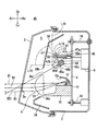
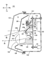
- FIG. 1st Example. II sectional drawing of FIG. A
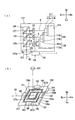
- the enlarged view of the laser light source unit of FIG. B
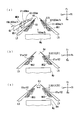
- disconnected the vehicle lamp of 2nd Example in the same position as FIG. The block diagram explaining a control device.
- Explanatory drawing regarding drawing by the laser beam ahead of a vehicle A
- B The figure which shows the modification of the mark of Fig.7 (a).
- A An explanatory view in which a road surface drawing is drawn by a laser beam to notify a following vehicle on an adjacent lane of a lane change.
- B An explanatory view in which a mark or the like for informing the vehicle width of the host vehicle is drawn on the road surface by a laser beam.
- A An explanatory view in which a mark for alerting about the presence of a vehicle or a pedestrian or the like in the opposite lane at an intersection is drawn on the road surface by a laser beam.
- B An explanatory view in which a mark for alerting a two-wheeled vehicle trying to slip through from the rear left of the vehicle at an intersection is drawn on the road surface by a laser beam.
- Explanatory drawing which carried out the road surface drawing of the mark etc. for calling on a driver the deceleration of self-vehicles, or deceleration.
- Explanatory drawing which drew the grid diagram of the grid
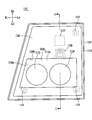
- the front view of the vehicle lamp of 3rd Example which has DRL.
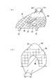
- the II sectional drawing of FIG. (A) The enlarged view of the laser light source unit of FIG. (B) The perspective view which looked at the light distribution part of FIG. 15 from the vehicle front.
- FIG. 26 is an II cross-sectional view of FIG. 25.
- FIGS. 1 to 13 show a first embodiment of a vehicular lamp according to the present invention for emitting laser light forward through an optical mechanism 8.
- FIG. 5 shows that laser light is emitted forward directly from the laser light source unit 2 shows a second embodiment of a vehicular lamp according to the present invention.
- 6 to 11 show a drawing mode by laser light performed in the vehicle lamp of the first and second embodiments
- FIG. 12 shows a third embodiment of a vehicle lamp having a DRL
- FIG. The 4th Example of the vehicle lamp which made the AO element the optical mechanism is shown.
- the vehicle lamp 1 of the first embodiment shown in FIG. 1 and FIG. 2 shows an example of a right side headlight, and a lamp body 2 having an opening on the front side of the vehicle and an opening of the lamp body 2 And a front cover 3 attached to the
- the front cover 3 is a translucent member formed of a translucent resin or glass.
- An optical mechanism 8 for drawing a figure such as a line or a drawing, a control device 9 for controlling emission and scanning of laser light, and an extension reflector 34 as a light shielding member are accommodated.
- the light distribution pattern forming light may be made yellow in consideration of a conventional fog lamp or the like.
- the optical mechanism 8 shown in FIG. 2 and FIG. 3B is a MEMS mirror, and the laser light B2 such as red from the laser light source unit 7 is forward in the reflection point (light emission end 32a) of the reflection part 32.
- a straight line horizontally extended forward from the light emitting end 32a of the optical mechanism 8 is represented by a symbol L11
- a straight line extended upward from the emitting end 32a is represented by a symbol L12.
- An area surrounded by L12 is represented by a symbol Ar1.
- the extension reflector 34 is shielded from light from a position at least above the emitting end 32a (a position on the straight line L12) to a front horizontal position (a position on the straight line L1), ie, surrounded by at least straight lines L11 and L12. It arrange
- the upper end edge 34b of the opening 34a of the extension reflector 34 may be disposed below the straight line L11, and the rear end 34d may be disposed rearward of the straight line L12.
- the laser light makes the person who looked straight on feel a very strong glare.
- the emitting end 32a in the present embodiment is covered from the horizontal direction to the upper side by the front extension reflector 34, pedestrians in front of the vehicle, drivers of oncoming vehicles, etc.
- the emission end 32a can not be viewed from above.
- the vehicle lamp forming the headlight is generally easily disposed at a position (for example, 1 m or less) lower than the line of sight of a person, and the laser beam B2 reflected forward by the emitting end 32a is horizontal Since the light directed obliquely upward can be emitted only obliquely downward by being cut at the upper end edge 34b of the extension reflector 34, the driver of the pedestrian or oncoming vehicle ahead of the vehicle reflects the laser light other than white It can not be recognized that the emitting end 32a forms the light source of the headlight.
- the reflecting portion 32 of the optical mechanism 8 is disposed so that the laser light B2 reflected by the emitting end 32 a is incident on the transmission area 3 a of the front cover 3. Is more desirable.
- the laser beam B2 reflected by the emitting end 32a intersects the light flux B1 of the white light distribution pattern forming light in the transmission area 3a.
- the light transmitting member such as the front cover 3 may emit light such as red due to diffuse reflection generated at the attachment site of the stains. .
- the laser beam B2 such as red in the vehicle lamp 1 of the first embodiment intersects the luminous flux B1 of the light distribution pattern forming light of white having higher luminance with the transmission area 3a, the red etc. generated in the front cover The diffusely reflected light is extinguished by the white light and is not visible from the front.
- the driver or the like of the oncoming vehicle can not recognize that the headlight is configured by laser light other than white such as red.
- the LED light source unit (5, 6) for generating the light distribution pattern forming light includes the metal bracket 10 fixed to the support member 4, the LED light emitting element 11 attached to the bracket 10, the reflector 12, and the transparent or semitransparent And the projection lens 13 of FIG.
- the LED light source unit 5 forms a high beam light distribution pattern
- the LED light source unit 6 forms a low beam light distribution pattern.
- the light beam B1 of the light distribution pattern forming light emitted from the LED light emitting element 11 is reflected forward by the reflection surface 12a of the reflector 12, passes through the projection lens 13 and the transmission area 3a of the front cover 3 and is emitted forward of the vehicle .
- the laser light source unit 7 and the optical mechanism 8 shown in FIG. 1 and FIG. 2 are attached to the support member 4 so as to be located above the LED light source unit 6 forming the low beam light distribution pattern.
- it is attached to the lamp body 2 by three) aiming screws 14.
- the optical mechanism 8 is fixed to the front end of a fixing portion 33 projecting forward of the support member 4.
- the controller 9 is fixed to the lamp body 2.
- the vehicle lamp 1 has its optical axis adjusted in the horizontal direction and the vertical direction by rotating the aiming screws 14.
- the laser light source unit 7 shown in FIG. 3A includes a first light source 15 that generates red light (see code R), a second light source 16 that generates green light (see code G), and blue light (code A third light source 17 for generating B), a heat radiation member 18 formed of metal such as aluminum having high thermal conductivity, first to third condenser lenses (20 to 22), and a condenser 24.
- the heat radiation member 18 is also attached to the support member 4 made of metal, and the laser light source unit 7 is fixed to the front surface of the support member 4 by the heat radiation member 18.
- the first to third light sources (15 to 17) shown in FIG. 3A generate laser lights of red, green and blue, respectively.
- the first to third light sources (15 to 17) are composed of red, green and blue laser diodes (15a, 16a and 17a) which are semiconductor laser elements and substrates (15b, 16b and 17b), respectively.
- the substrates (15b to 17b) are attached to the heat dissipation member 18, respectively.
- the light source of the laser light source unit 7 is not limited to the configuration having three RGB light sources, but may be a single monochromatic light source, four light sources in which an orange laser diode is added to three RGB, or a blue laser White light may be generated by providing a configuration in which the light emitted from the diode is allowed to pass through the yellow phosphor.
- each light source may be comprised by other laser devices other than a laser diode.
- Each of the first to third condenser lenses (20 to 22) shown in FIG. 3A is formed of a collimator lens or the like.
- the condensing unit 24 has first to third dichroic mirrors (25 to 27).
- the red laser light R emitted from the first light source 15 is converted into parallel light by transmitting through the first condenser lens 20, and then is transmitted by the first dichroic mirror 25.
- the light is directly reflected toward a reflecting portion 32 of the optical mechanism 8 described later.
- the green laser light G emitted from the second light source 16 is transmitted through the second condenser lens 21 and converted into parallel light, and then reflected by the second dichroic mirror 26 and transmitted through the first dichroic mirror 25.
- the light is incident on the reflecting portion 32 of the optical mechanism 8.
- the blue laser light B emitted from the third light source 17 passes through the third condenser lens 22 and is converted into parallel light, and then is reflected by the third dichroic mirror 27 and is reflected by the second and first dichroic mirrors (26, After sequentially transmitting 25), as shown in FIG. 3 (b), the light is incident on the reflection part 32 of the optical mechanism 8. As shown in FIG.
- the red laser light R, the green laser light G and the blue laser light B reflected by the light collecting portion 24 become laser light B2 having a composite color, and as shown in FIG. I aim at and emit.
- the extension reflector 34 in the lamp chamber S has an opening 34a, and the projection lenses 13 of the LED light source units (5, 6) are exposed forward from the opening 34a.
- the laser light source unit 7 and the optical mechanism 8 are disposed on the rear side of the extension reflector 34 above the LED light source unit 6 which forms a low beam light distribution pattern.
- the optical mechanism 8 shown in FIG. 3B is a MEMS mirror, and includes a base 37, a first rotating body 38, a second rotating body 39, a first torsion bar 40, a second torsion bar 41, a permanent magnet 42, 43 and a terminal portion 44.
- the plate-shaped base portion 37 and the first rotating body 38 have openings (37a, 38a) at the center, respectively, and the front surface of the plate-shaped second rotating body 39 is reflected by processing such as silver deposition or plating.
- the part 32 is formed.
- various optical mechanisms such as a galvano mirror can be adopted as the optical mechanism 8.
- the first rotating body 38 is rotatably supported to the left and right with respect to the base portion 37 by a pair of first torsion bars 40 provided at the upper and lower end portions (37b, 37c) of the opening 37a.
- the moving body 39 is rotatably supported vertically with respect to the first rotating body 38 by a pair of second torsion bars 41 provided at left and right end portions (38b, 38c) of the opening 38a.
- the base portion 37 and the first and second rotating bodies (38, 39) are fixed to the fixed portion 33 of the support member 4 shown in FIG. 2 in a state of being inclined downward with respect to the longitudinal direction of the vehicle lamp as shown in FIG. It is fixed to
- the base portion 37 is provided with a pair of permanent magnets 42 at a position orthogonal to the extending direction of the first torsion bar 40, and further orthogonal to the extending direction of the second torsion bar 41.
- the pair of permanent magnets 43 is provided at the position where The first and second rotating bodies (38, 39) are respectively provided with first and second coils (not shown).
- the permanent magnet 142 forms a magnetic field orthogonal to the first torsion bar 140
- the permanent magnet 143 forms a magnetic field orthogonal to the second torsion bar 141.
- the first and second coils (not shown) are connected to the controller 109 via the terminal portion 144.
- the first coil and permanent magnet 42 and the second coil and permanent magnet 43 constitute a scanning actuator 35 of FIG. 5 described later.
- the scanning actuator 35 rotates the first rotating body 38 up and down with respect to the base portion 37 by individually changing the magnitude and direction of the drive current flowing through the first and second coils, and the second time
- the moving body 39 is pivoted to the left and right with respect to the first pivoting body 38.
- the direction of the reflecting portion 32 changes vertically and horizontally based on the rotation of the first and second rotating bodies (38, 39).
- the optical mechanism 8 shown in FIG. 2 and FIG. 3 (b) reflects the laser beam B2 emitted from the laser light source unit 7 of FIG.
- the laser beam B2 reflected forward at the emission end 32a (reflection point) of the reflecting portion 32 scans the front of the vehicle by reciprocating the reflecting portion 32 of the second rotating body 39 vertically and horizontally.
- the light beam B1 of the low beam light distribution pattern forming light emitted from the projection lens 13 of the LED light source unit 6 shown in FIG. 2 is emitted forward from the transmission area 3a of the front cover 3 in front.
- the emitted light B2 from the laser light source unit 7 is reflected obliquely downward by the reflecting portion 32 of the optical mechanism 8, and the upper end edge 34b of the opening 34a and the LED light source unit (5 , 6) and then exit from the front cover 3 in the forward direction.
- the optical mechanism 8 as shown in FIG. 2, it is desirable to dispose the reflecting portion 32 so that the reflected light B2 is incident on the transmission area 3 a of the front cover 3. In that case, when the laser light B2 passes through the transmission area 3a of the front cover 3, it crosses with the white light distribution pattern forming light B1 with high brightness, and thus irregular reflection generated due to dirt or the like of the front cover 3 is erased. .
- a vehicle lamp 45 of the second embodiment is shown in FIG.
- the vehicle lamp 45 of the second embodiment is obtained by replacing the laser light source unit 7 and the optical mechanism 8 of the vehicle lamp 1 of the first embodiment with a laser light source unit 46, and the other configuration is the first embodiment.
- the same as the vehicle lamp 1 of The laser light source unit 46 directly emits the laser beam B21 to the front cover 3 without the optical mechanism 8 as in the first embodiment.
- the laser light source unit 46 shown in FIG. 4 includes a laser diode 46a, a substrate 46b and a heat sink 46c for mounting the substrate 46b, and is attached to the support member 4 by a link mechanism 47.
- the link mechanism 47 includes a first link 47a fixed forward from the support member 4 and a second link 47b rotatably mounted around the horizontal rotation axis L13 of the first link 47a.
- the laser light source unit 46 is attached to the second link 47 b.
- the support member 4 is provided with an actuator mechanism 48 for advancing and retracting the arm 48a back and forth, and the second link 47b is connected to the tip of the arm 48a of the actuator mechanism 48 via an elastic member 47c such as rubber.
- the laser light source unit 46 and the second link 47b swing around the horizontal rotation axis L13 based on the forward and backward movement of the arm 48a.
- the direction of the laser beam B21 emitted from the laser light source unit 46 is upward Change.
- the second link 47b pivots in the counterclockwise direction D2 due to the backward movement of the arm 48a, the direction of the laser beam B21 changes downward.
- the laser light source unit 46 is attached to the second link 47b so as to be rotatable around the central axis L14 of the second link 47b, and is oscillated around the central axis L14 by a motor (not shown). The direction of the laser beam B21 changes from side to side by the motor (not shown).
- the vehicle lamp 45 of the second embodiment draws a figure on a road surface or the like in front of the vehicle by scanning the direction of the laser beam B21 back and forth and right and left with the actuator mechanism 48 and a motor not shown.
- the light emitting operation of the laser light source unit 46, the advancing and retracting operation of the arm 48a of the actuator mechanism 48, and the rotational operation of the laser light source unit 46 by a motor (not shown) are all controlled by the control device 9 connected.
- the actuator mechanism 48 and a motor not shown constitute a scanning actuator 49 of FIG.
- the light emitting end 46d of the laser diode 46a has a horizontal position (a position on a straight line L16 extending vertically upward from the emitting end) at least upward as in the case of the emitting end 32a of the first embodiment shown in FIG.
- the light is shielded by the extension reflector 34 to a position on a straight line L15 horizontally extending forward of the emission end, and the laser light source unit 46 is obliquely drawn downward toward the front cover 3 via the gap 34c of the opening 34a. It emits laser light.
- a pedestrian or the like in front of the vehicle can not visually recognize the emission end.
- the laser light source unit 46 be directed to the transmission area 3 a of the front cover 3 through which the light flux B 1 of the LED light source unit 6 passes.
- the laser light B21 emitted from the laser light source unit 46 intersects with the white light distribution pattern forming light B1 having higher luminance, so that the irregular reflection generated due to the contamination of the front cover 3 or the like is wiped out.
- control device 9 shown in FIG. 5 includes a lamp ECU (electronic control device) 51, a ROM 52, a RAM 53, and the like.
- the lamp ECU 51 includes an actuator control unit 36 and a laser light source control unit 54.
- Various control programs are recorded in the ROM 52, and the lamp ECU 51 executes the control programs recorded in the ROM 52 in the RAM 53 to generate various control signals.
- the laser light source control unit 54 controls the color of the laser light by the first to third light sources (15 to 17), the emission intensity of the first to third light sources (15 to 17) and the laser light source unit 46 and on / off for each light source. Control.
- the actuator control unit 36 controls the scanning actuators (35, 49) to scan the front of the vehicle with the laser beam B2 and draws a figure such as a mark or a character to alert a driver or a pedestrian etc. to a road surface around the vehicle And draw on buildings.
- the image processing device 55 raindrop sensor 56, navigation system 57, speedometer 58, road information communication system 59, turn signal lamp switch 64, steering operation detection mechanism 65, accelerator opening detection mechanism 71 etc. are connected to the ECU 51. Be done.
- An on-vehicle camera 60, a road surveillance camera 61, and the like are connected to the image processing device 55.
- the image processing device 55 sends to the lamp ECU 51 data obtained by analyzing and processing an image or the like related to a road or a building taken by the on-vehicle camera 60 or a road monitoring camera 61 or the like such as an intersection camera connected via a communication line.
- the system 57 sends a data signal regarding the current position of the vehicle to the lamp ECU 51.
- the lamp ECU 51 is a video data of the image processing apparatus 55, the condition of the vehicle on the road obtained from the navigation system 57, the road condition such as wet or frozen obtained from the data of the raindrop sensor 56 and the road information communication system 59, etc.
- a predetermined figure that warns the driver of the host vehicle or other vehicles is a road surface etc.
- the laser light source unit 7 and the optical mechanism 8 are controlled so as to draw at a predetermined position.
- the optical mechanism 8 of the first embodiment and the laser light source unit 46 of the second embodiment change the direction of the laser beam (B2, B21) vertically and horizontally to lower the inside of the rectangular area (symbol Sc1) in front of the vehicle.
- the scanning is repeated repeatedly to the left and right while being shifted by a minute length.
- the reference symbol S1 indicates the locus of the scanning line by the optical mechanism 8 and the laser light source unit 46, the broken line part of the scanning line S1 indicates the non-lighting, and the solid line part indicates the lighting.
- Laser light (B2, B21) draws figures such as characters and marks by being stacked up and down in the horizontal direction during lighting.
- predetermined figures drawn to draw attention to the driver of the own vehicle or another vehicle using the vehicle lamps (1, 45) of the first and second embodiments will be listed.
- laser light such as red is illuminated along the lane mark M1 (portion indicated by the two-dot chain line) on the road surface R1 illuminated by the white low beam light distribution pattern Lb and located by the on-vehicle camera 60 etc. Is drawing a line L1.
- the driver recognizes the position of the lane mark by visually recognizing the line L1.
- the driver can avoid a lane departure accident by being able to accurately recognize the curved direction of the road in advance.
- the low beam light distribution pattern Lb is formed as a combined light distribution pattern of white laser light scanned by the LED light source unit 6, the laser light source unit 7 and the optical mechanism 8, a line L1 formed inside the white light distribution pattern. It is desirable to form a dark part by reducing (including turning off) the white laser light in the periphery of the and other marks in order to make the line L1 and the marks stand out.
- the stoppable distance is automatically calculated from the traveling speed of the vehicle and the road surface condition by the drawing system of the vehicle lamp (1, 45), and the stoppable inter-vehicle distance is calculated.
- the figure which drew the mark etc. which were shown on the road surface with a laser beam is shown.
- the lamp ECU 51 calculates the braking distance according to the speed of the vehicle obtained by the speedometer 58, the raindrop sensor 56, the road information communication system 59, etc. and the amount of rainfall on the road surface during traveling and freezing. In accordance with the degree of depression of the vehicle, a plurality of marks indicating the positions at which the vehicle can stop are drawn on the road surface.
- the braking distance at which the host vehicle My traveling on a road surface at rainy weather 60 km / h can be stopped by gentle braking operation is 90 m
- the braking distance at which braking can be stopped by strong normal braking operation is 70 m
- the lamp is calculated to be 50 m
- the vehicle lamp (1, 45) is a rectangular first green mark 62a in the range of 70 m to 90 m ahead of the vehicle and a second rectangular yellow mark 62 b in the range of 50 m to 70 m.
- a rectangular third red mark 62c or the like is drawn in front of the host vehicle My in a range of 50 m or less.
- the first to third marks do not differ in color as long as they indicate that the risk of a rear-end collision is increased, and marks having different shapes such as ⁇ , ⁇ , and ⁇ (63a in FIG. 7 (b) To 63 c)).
- FIG. 8A is a diagram in which a mark or the like for notifying a driver of a following vehicle in a lane adjacent to the lane change of the host vehicle is drawn on the road surface by a laser light by the vehicle lamp (1, 45).
- the vehicle lamp (1, 45) the lane change direction of the own vehicle detected by the turn signal lamp switch 64 and the steering operation detection mechanism 65 is detected, and based on the detection result, from the traveling lane R11 of the own vehicle My First to third arrow marks (66 to 68) indicating the lane change are drawn to the adjacent lane R12 where the lane change is to be made.
- the driver of the other vehicle Otr can avoid a contact accident by visually recognizing the first to third arrow marks (66 to 68) in front even if the turn signal lamp of the host vehicle My can not be seen.
- FIG. 8B a mark or the like that indicates the vehicle width of the host vehicle is drawn on the road surface in front of the host vehicle using a laser beam.
- the vehicle lamps (1, 45) form lines (L3, L4) by laser light in front of the vehicle along the left and right side ends (My1, MY2) of the vehicle My.
- the driver operates the steering to prevent the drawn lines (L3, L4) from coming into contact with the obstacle Ms in front of the host vehicle My, thereby preventing a contact accident. It can be avoided.
- FIGS. 9 (a) and 9 (b) are diagrams on which a mark for alerting about the passage of a vehicle, a pedestrian or the like in the vicinity of an intersection is drawn on a road surface by a laser beam.
- FIG. 9A shows a case where the vehicle turns right while facing the right turn vehicle in the opposite lane.
- the symbol My indicates the own vehicle
- the symbol Ott indicates another right-turn vehicle on the opposite right-turn lane
- the symbol Ots indicates the other straight ahead vehicle on the opposite lane
- the symbol Hu indicates a pedestrian while crossing
- the symbol R3 indicates the road surface at the intersection. .
- the lamp ECU 51 calculates. Further, the lamp ECU 51 detects from the turn signal lamp switch 64 or the steering operation detection mechanism 65 whether the vehicle is going to bend to the left or right.
- the vehicle lamp (1, 45) when it is detected that the oncoming vehicle Ots approaches the oncoming traffic lane R13 or the pedestrian Hu is on the pedestrian crossing, the vehicle lamp (1, 45) The driver of the host vehicle My and the oncoming vehicle Ots is made aware of the danger of turning to the right by drawing a mark consisting of framed characters etc. "STOP" on the road surface R3 in the traveling direction with a laser beam such as red. Further, as shown in FIG. 9 (b), when the motorcycle Bk which tries to slip through the left side of the host vehicle My is detected from behind, the vehicle lamp (1, 45) is on the road surface R3 in the traveling direction.
- the rider of the motorcycle Bk is made aware of the risk of being caught in a left turn. Also, by drawing a mark such as a framed letter "BIKE! Indicating the presence of the motorcycle Bk on the road surface in the traveling direction of the own vehicle MY with a laser light such as red, the driver of the own vehicle also has the motorcycle Bk. Make them aware of the risk of getting caught in a left turn.
- FIG. 10 is a drawing in which marks and the like for prompting an increase in speed for the driver to suppress excessive speeding of the host vehicle or to eliminate traffic congestion are drawn on the road surface by laser light.
- a plurality of marks M51 shown in FIG. 10 are a plurality of rectangular marks drawn intermittently in the longitudinal direction of the road surface by laser light such as red, and the plurality of marks M52 are positioned by the on-vehicle camera 60 etc.
- the plurality of rectangular marks are drawn intermittently in the front-rear direction with respect to the identified guard rail GL.
- the driver senses the traveling speed of the own vehicle by visually recognizing a structure on the road such as a guard rail GL moving backward with respect to the own vehicle at the traveling speed of the own vehicle My while traveling.
- the vehicle lamp (1, 45) is in the traveling direction or the reverse direction of the own vehicle at a speed faster or slower than the speed of the own vehicle My while driving the marks (M51, M52) drawn on the road surface R4 and the guard rail GL. Move it.
- the mark (M51, M52) is moved in the reverse direction, the driver feels that the traveling speed of the host vehicle My is faster and the host vehicle My is decelerated as the moving speed of the mark M51 to the rear increases. The slower the moving speed to the rear of the mark (M51, M52), the slower the traveling speed of the host vehicle My is felt, and it is called to accelerate the host vehicle My.
- the structure on the road looks shorter from the traveling driver in the traveling direction as the speed of the host vehicle My increases. Therefore, when the vehicular lamp (1, 45) draws the front-rear length L51 of the mark M51 shorter, the drawing driver feels the traveling speed of the host vehicle My faster and is called for deceleration, and the front-rear length L51 becomes longer The more the driver draws, the slower the traveling speed of the host vehicle My feels, and the driver is decelerated.
- FIG. 11 shows a grid-like grid diagram drawn around the vehicle by laser light such as red.
- a vehicle lamp (1, 45) irradiates the grid diagram PG to the road surface R5, the roadway groove C1, the depressed hole C2 and the dropped object C3 etc. in front of the vehicle by laser light such as red light inside and outside the low beam light distribution pattern PL.
- the grid diagram PG is curved or shredded based on the unevenness of the irradiated place, thereby making the shapes of the side grooves C1 and the like stand out and making it easy for the driver to grasp those shapes and positions.
- FIG. 12 shows a third embodiment of the vehicular lamp.
- the vehicle lamp 73 of FIG. 12 has two LED light source units for forming a high beam and a low beam tiltably attached to the inside of the lamp body 74 via a lamp body 74, a front lens 75, an aiming screw 78 and a support member 79. (76, 77), a DRL unit 80 having a plurality of LED light emitting elements 81, a laser light source unit (not shown), and an optical mechanism 82 having a reflecting portion 83 which can be tilted vertically and horizontally.
- the emission end 84 (reflection point) of the reflection part 83 that reflects the laser light is exposed forward from the plurality of LED light emitting elements 81.
- the emission end 84 even if it reflects laser light other than white, loses its emission color by the plurality of LED light emitting elements 81 with high brightness, and therefore is not visually recognized by the pedestrian in front or the driver of the oncoming car.
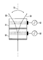
- FIG. 13 is an explanatory view of a fourth embodiment of an AO element used in place of the MEMS mirror used in the vehicle lamp 1 of the first embodiment.
- the AO element (Acousto-Optic-Device) causes a periodic change in refractive index by being loaded with a high frequency electric signal.
- the laser beam passed through the AO element to which the high frequency electrical signal is applied is linearly scanned.
- two AO elements (90, 91) respectively connected to high frequency electric signal applying means (92, 93) are arranged in series.
- the laser beam that has passed through the AO element 90 is scanned in a straight line by being periodically refracted, and the laser light that has been straightened is refracted again by the AO element 91, and a wider range is linearly shaped. It is scanned.
- the AO elements (90, 91) Next to the AO elements (90, 91), another set of the same AO elements (90, 91) (not shown) is connected in series in a state rotated 90 degrees with respect to the straight line L6 indicating the incident line direction of light. It is desirable to arrange (the other set of AO elements is not shown).
- the laser beam B2 which is incident on the first set of AO elements (90, 91) and scanned in a line in the vertical direction is rotated by 90 degrees and the second set of AO elements (shown in FIG. It is scanned in the left-right direction by entering into.
- the plurality of AO elements arranged in series in the state of being rotated 90 degrees in this manner enable scanning of planar laser light in the vertical and horizontal directions.
- FIGS. 14 to 17 show a fifth embodiment of the vehicle lamp according to the present invention
- FIG. 18 shows a sixth embodiment of the vehicle lamp from which the LED light source unit is removed from the fifth embodiment
- FIGS. 19-24 show a drawing system used for the vehicle lamp of the fifth and sixth embodiments.
- the vehicle lamp 101 of the fifth embodiment shown in FIGS. 14 and 15 shows an example of a right side headlamp, and the configuration thereof is substantially the same as the vehicle lamp 1 shown in FIGS. 1 and 2. is there.
- the configuration of the laser light source unit 107 shown in FIG. 16A is the same as that of the vehicle lamp 1 of the first embodiment except that the fourth condensing lens 123 is provided.
- the condensing unit 124 includes first to third dichroic mirrors (125 to 127).
- the first to third condenser lenses (120 to 122) and the first to third condensing lenses (120 to 122) are provided on the optical paths of the red laser light R, the green laser light G and the blue laser light B emitted from the respective light sources (115 to 117).
- the dichroic mirrors (125 to 127) are arranged in order.
- the first dichroic mirror 125 is configured to reflect red light and transmit blue light and green light
- the second dichroic mirror 126 is configured to reflect green light and transmit blue light
- the three dichroic mirror 127 is configured to reflect blue light.
- the red laser light R emitted from the first light source 115 is converted into parallel light by transmitting through the first condenser lens 120, and then the fourth collection is performed by the first dichroic mirror 125. It is directly reflected toward the light lens 123.
- the green laser light G emitted from the second light source 116 is transmitted through the second condenser lens 121 and converted into parallel light, and then reflected by the second dichroic mirror 126 and transmitted through the first dichroic mirror 125.
- the light is incident on the fourth condenser lens 123.
- the blue laser light B emitted from the third light source 117 is transmitted through the third condenser lens 122 and converted into parallel light, and then reflected by the third dichroic mirror 127 toward the fourth condenser lens 123, The light is transmitted through the second and first dichroic mirrors (126, 125) in order, and then enters the fourth condenser lens 123.
- the fourth condenser lens 123 is attached to the opening 107 a of the housing of the laser light source unit 107.
- the red laser light R, the green laser light G, and the blue laser light B reflected by the light collecting unit 124 become laser light B2 having a composite color.
- the combined laser beam B2 passes through the fourth condenser lens 123, is converted into parallel light, and then emits toward the optical mechanism 108.
- the extension reflector 134 in the lamp chamber S has an opening 134a.
- the LED light source unit (105, 106) is attached to the support member 104 in a state where each projection lens 113 is exposed in front of the opening 134a in order to emit light B1 emitted by the LED light emitting element 111 forward from the opening 134a.
- Be The laser light source unit 107 and the optical mechanism 108 are both concealed from the front of the vehicle by being disposed behind the extension reflector 134 above the opening 134 a.
- the emitted light B2 from the laser light source unit 107 is emitted forward from a gap 134c formed between the upper end edge 134b of the opening 134a and the LED light source unit (105, 106).
- the optical mechanism 108 shown in FIG. 16B is a MEMS mirror, and the configuration thereof is common to the optical mechanism 8 of the first embodiment, so the detailed description will be omitted.
- the optical mechanism 108 is a reflecting portion 132 of the second rotating body 139 which is an emitting end for emitting the laser beam B2 emitted from the fourth condenser lens 123 of FIG. 16A forward. Reflect forward on the.
- the laser beam B2 reflected forward at the light emitting part 132a (reflection point) of the reflecting part 132 scans the front of the vehicle by reciprocating the reflecting part 32 of the second rotating body 139 in the vertical and horizontal directions.
- the LED light source units (105, 106) are switched to form white light distribution patterns of low beams and high beams of a predetermined shape.
- the optical mechanism 108 scans a white light distribution pattern for supplementing the low beam light distribution pattern or a figure pattern for calling a driver's attention to a road surface in front of the vehicle or a building with a laser light B2 other than white.
- the vehicle lamp 145 of the sixth embodiment is shown in FIG.
- the vehicle lamp 145 of the sixth embodiment is the same as the vehicle lamp 101 of the fifth embodiment except that the LED light source unit (105, 106) and the extension reflector 134 are omitted, and all the other configurations are the fifth embodiment.
- the low-light and high-beam white light distribution patterns are also separated by the laser light source unit 107 and the optical mechanism 108. It is formed by the white laser beam B2 scanned by.
- the low beam distribution pattern and the high beam distribution pattern may be separately formed by providing two combinations of the laser light source unit 107 and the optical mechanism 108, Three or more combinations of the laser light source unit 107 and the optical mechanism 108 may be provided.
- control device 109 will be described with reference to FIG.
- the configuration of the control device 109 is common to the control device 9 of the first embodiment.
- the laser light source control unit 154 independently controls, for each light source, emission intensities of various laser lights (R, G, B) by the first light source 115, the second light source 116, and the third light source 117 and turning on and off. It generates laser light of various synthetic colors.
- the actuator control unit 136 also controls the scanning actuator 135 of the optical mechanism 108 to scan the front of the vehicle with the laser beam B2 made of synthetic light, and draw a figure of a predetermined shape on the road surface or building around the vehicle. Do. In addition, in the figure of the predetermined shape, the driver's attention or the pedestrian or the like of the own vehicle or another vehicle is alerted by the light distribution pattern of the headlamp for the vehicle by the synthesized white laser light, and various synthetic colors. Includes marks and characters for
- FIG.19 (a) is explanatory drawing of figure drawing by the vehicle lamp 101 of 5th Example
- FIG.19 (b) is explanatory drawing of figure drawing by the vehicle lamp 145 of 6th Example.
- the optical mechanism 108 of the first and second embodiments shown in FIGS. 19 (a) and 19 (b) changes the upper and lower positions little by little in the rectangular scanning area (symbols Sc1 and Sc2) in front of the vehicle, respectively. The scanning from the left to the right of the vehicle can be repeated.
- the extension reflector 134 for cutting light traveling upward from the horizontal direction is not provided in front of the optical mechanism 108. Therefore, the optical mechanism 108 of the sixth embodiment can scan the scan area Sc2 wider than the scan area Sc1 of the optical mechanism 108 of the fifth embodiment, thereby a light distribution pattern for high beams or a road surface further away. You can draw figures on obstacles and obstacles.
- the symbol S1 indicates the locus of the scanning line by the optical mechanism 108.
- the optical mechanism 108 rotates the reflecting portion 132 (see FIG. 16B) from left to right to scan from left to right.
- the reflection unit 132 is pivoted to the lower left, and the direction of the reflection unit 132 is returned to the next scanning start position shifted downward by the minute distance d1 from the first scanning start position, and from the left again Repeat the operation of scanning to the right.
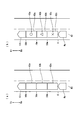
- the laser light source control unit 154 shown in FIG. 18 controls the first to third light sources (115 ⁇ ) when moving the scanning line S1 in FIGS. 19 (a) and 19 (b) from the left to the right by the optical mechanism 108.
- 117 is turned on and off, and all of the first to third light sources (115 to 117) are turned off when the scanning line S1 is returned from the right to the next lower scanning start position by the optical mechanism 108.
- the dotted line portion of the scanning line S1 shown in FIGS. 19A and 19B indicates a range in which all of the first to third light sources (115 to 117) are turned off, and the solid line portion of the scanning line S1 indicates the first to third light sources.
- a part or all of the third light source (115 to 117) is turned on to indicate a range in which a figure by laser light is drawn on the road surface.
- the on / off control of the first to third light sources (115 to 117) in the optical mechanism 108 may be performed while moving the scanning line S1 from right to left, or may be performed while reciprocating left and right. This is not necessarily performed only when moving from the left to the right as in this embodiment.
- FIG. 19A a low-beam light distribution pattern Lb of the first white light in front of the vehicle, and a line of a color other than white that causes the driver to recognize the position of the lane mark M1 (a portion indicated by a two-dot chain line).
- the figure which drew L1 on road surface R1 with a laser beam is shown.
- the line L1 is drawn as a line such as red on the lane mark M1 or adjacent to the lane mark M1.
- the method of detecting the position of the lane mark M1 and the like will be described later.
- the low beam light distribution pattern Lb in the vehicle lamp 101 of the fifth embodiment is formed by combining the light B1 by the LED light source unit 105 and the laser beam B2 synthesized and scanned in white, and the sixth embodiment
- the low beam light distribution pattern Lb in the vehicle lamp 145 is formed only by the laser beam B2 synthesized and scanned in white.
- the laser light source control unit 154 when scanning from the left to the right by the optical mechanism 108, the laser light source control unit 154 first performs the first to third in the section from P1 to P2 in which drawing is not performed. Turn off all the light sources (115 to 117). Next, the laser light source control unit 154 is synthesized under control of the first to third light sources (115 to 117) in the section from P2 to P3 in which the low beam light distribution pattern Lb is drawn on the road surface R1 and the object in front of the vehicle. And the second and third light sources (116, 117) turn off the green and blue laser beams in the section from P3 to P4, which generates the white laser beam and then draws the line L1 of the red laser beam on the road surface.
- the irradiation intensity of the first light source is adjusted to generate red laser light of a predetermined luminance.
- the laser light source control unit 154 causes the first to third light sources (115 to 117) to generate white laser light in the section from P4 to P5, and generates red laser light to the first light source in the section from P5 to P6.
- the first to third light sources (115 to 117) generate white laser light in the section from P6 to P7, and the first to third light sources (115 to 117) in the section from P7 to P8 after the end of drawing Turn off all lights.
- the white laser light synthesized by the laser light source unit 107 is together with the light from the LED light source unit 105 (in the fifth embodiment),
- the low beam light distribution pattern Lb of the headlight is drawn on the road surface and an object in front of the vehicle alone (in the case of the sixth embodiment), and the red laser light is a road surface of two lines L1 indicating the position of the lane mark M1.
- Draw on In the laser light source unit 107 and the optical mechanism 108 a low beam light distribution pattern of white light may be formed by a predetermined scan, and the color of the line L1 is not only red but also the first to third light sources.
- a wide variety of colors obtained by synthesizing the laser light of (115 to 117) can be adopted.
- the means for drawing a graphic to draw attention to the driver is not limited to the line L1, and various marks as will be described later can be considered.
- FIG. 19B is a diagram in which the dark portion D1 is added with the lane mark M1 of FIG. 19A omitted for the sake of clarity.
- a procedure for forming a red line L1 to be a bright portion inside the dark portion D1 in the inner region of the white low beam light distribution pattern Lb will be described with reference to FIGS. 19 (b) and 20.
- the symbols (R, G, B) in FIG. 20 indicate the lighting states and the extinguishing states of the first to third light sources (115 to 117).
- the symbols W and R indicate the magnitude of the output of the light source, and the output R has a higher irradiation intensity than the output W.
- Each light source generates white laser light by lighting up all at the output W.
- the first light source 115 for generating the red laser light is not turned off, and the irradiation intensity is increased to the output R at a predetermined timing.
- the second and third light sources (116, 117) are turned off at the "OFF" position.
- the laser light source control unit 154 in FIG. 18 turns off all of the first to third light sources (115 to 117) in the section from P11 to P12 where drawing is not performed and in P21 to P22 shown in FIG.
- a low beam light distribution pattern Lb by white laser light, a dark portion D1 and a red line L1 by red laser light are drawn on an object on the road surface or in front of a vehicle.
- the laser light source control unit 154 performs white laser light while lighting the first to third light sources (115 to 117) with the output W in the section from P12 to P13. It is generated to form a low beam light distribution pattern Lb.
- the laser light source control unit 154 does not change the irradiation intensity of the first light source 115 in the section from P13 to P14, and turns off only the second and third light sources (116, 117) to obtain a white low beam light distribution pattern Lb.
- a dark portion D1 is formed inside.
- the white is reduced and the dark portion D1 is formed.
- the white is turned off to form the dark portion D1.
- the laser light source control unit 154 increases the output of the first light source 115 from the output W to the output R in the section from P14 to P15, thereby forming a line L1 of red laser light adjacent to the dark part D1.
- the laser light source control unit 154 also decreases the output of the first light source 115 from the output R to the output W again in the section from P15 to P16, thereby forming a dark portion D1 adjacent to the red line L1.
- the second and third light sources (116, 117) are turned on again with the output W to generate white laser light together with the first light source 115 of the same output, and white low beam light distribution continuous to the dark part D1.
- Form a pattern Lb As a result, the red line L1 surrounded by the dark part D1 is drawn sharply on the inside of the white low beam light distribution pattern Lb.
- the laser light source control unit 154 also performs the same control as described above for the first to third light sources (115 to 117) to form a dark portion D1 in the section from P17 to P18, and performs P18 to P19.
- a red line L1 is formed in the section
- a dark portion D1 is formed in the section from P19 to P20
- a white low beam light distribution pattern Lb is formed in the section from P20 to P21.
- the optical mechanism 108 goes from left to right while the laser light source unit 107 generates predetermined laser light at predetermined timing as described above.
- the above-mentioned predetermined scanning of the above is repeated at high speed while sliding in the vertical direction, and a white light distribution pattern of a predetermined shape as a headlight or a laser of a predetermined shape which draws attention to a driver etc. It draws on the road surface or an object in front of the vehicle by light.
- the lamp ECU 151 shown in FIG. 18 includes an image processing device 155, a raindrop sensor 156, a navigation system 157, a speedometer 158, a road information communication system 159, a turn signal lamp switch 164, a steering operation detection mechanism 165, and an accelerator opening degree.
- the detection mechanism 171 and the like are connected.
- An on-vehicle camera 160, a road surveillance camera 161, and the like are connected to the image processing device 155.
- the on-vehicle camera 160 includes a camera which is mounted on the own vehicle or another vehicle and shoots the periphery of the vehicle as a moving image or a stop image
- the road monitoring camera 161 includes an intersection camera disposed at an intersection and the vicinity of the road.
- a surveillance camera for photographing a road surface condition, a pedestrian, a bicycle, a motorcycle, a vehicle such as a car, an obstacle or the like with a moving image or a still image.
- the image processing device 155 is connected to the road monitoring camera 161 via a communication line such as the Internet, and acquires video and image data from the road monitoring camera 161.
- the image processing device 155 sends to the lamp ECU 151 data analyzed and processed an image or the like taken by the on-vehicle camera 160 or the road monitoring camera 161 etc.
- the raindrop sensor 156 sends to the lamp ECU 151 a data signal related to rainfall during vehicle travel. .
- the navigation system 157 transmits a data signal related to the current position of the vehicle to the lamp ECU 151 by, for example, having GPS and map data (not shown). Further, the lamp ECU 151 receives a signal from the speedometer 158 regarding the traveling speed of the vehicle.
- the road information communication system 159 receives, via a communication line such as the Internet, data on the road surface condition during traveling, such as the rainfall on the road during traveling and the freezing condition of the road, and sends it to the lighting ECU 151.
- the lamp ECU 151 analyzes the situation regarding the host vehicle and the like on the road based on the above data and the road surface condition, and then draws a predetermined figure on the road surface and the like for alerting the driver of the host vehicle and other vehicles. , And control the laser light source unit 107 and the optical mechanism 108.
- the means for drawing predetermined figures that draw attention to the driver of the own vehicle or another vehicle using the vehicle lamps (101, 145) of the fifth and sixth embodiments will be listed below.
- the stoppable distance is automatically calculated from the traveling speed of the own vehicle from FIGS. 18 and 21 and a mark indicating the stoppable inter-vehicle distance is drawn on the road surface by laser light.
- a seventh embodiment of the drawing system for the lamp (101, 145) will be described.
- a forward vehicle When the driver of a running vehicle is suddenly decelerating due to a sudden stop or the like when another vehicle (hereinafter simply referred to as a forward vehicle) running forward, the driver can safely stop the vehicle without a collision.
- the vehicle must travel with an appropriate distance between the vehicle and the vehicle.
- the driver can not recognize the inter-vehicle distance from another vehicle.
- the braking distance of the vehicle changes depending on the speed of the vehicle, and also changes depending on the road surface conditions such as rainfall and freezing.
- the driver who is actually driving to recognize the distance between the vehicle ahead and the braking distance that can be safely stopped without hitting the vehicle ahead.
- a method using an image analysis system using a millimeter wave radar or an on-vehicle camera there is a method using an image analysis system using a millimeter wave radar or an on-vehicle camera.
- the millimeter wave radar can detect only a forward vehicle with an inter-vehicle distance of about 150 m, and there is a limit to the measurable inter-vehicle distance in that the in-vehicle camera also becomes difficult to catch the vehicle as it goes further.
- the braking distance of the own vehicle while traveling is automatically measured according to the traveling speed of the own vehicle and the road surface condition, and then taken between the vehicle and the preceding vehicle.
- the road surface is drawn by a laser beam to make the driver recognize the necessary inter-vehicle distance.
- the braking distance according to the vehicle speed and the amount of rainfall on the road surface during traveling and the presence or absence of freezing is calculated, and then the position at which the vehicle is actually stopped when emergency braking is performed. That is, a program for drawing a mark or the like by a laser beam at a position ahead of the vehicle by a braking distance is recorded in the ROM of FIG.
- the lamp ECU 151 automatically calculates the braking distance according to the speed of the vehicle obtained by the speedometer 158.
- the calculated braking distance for example, the first braking distance in which the vehicle can be stopped gently by stepping on the brake, the second braking distance in which the vehicle can be stopped by stepping on the brake with normal force, It is desirable to calculate a plurality of braking distances in consideration of a stoppable margin, such as a third braking distance consisting of a limit braking distance at which the vehicle can be stopped by stepping.
- the lamp ECU 151 can stop the shortest braking distance that can be stopped (third braking distance) 40 m, the second The braking distance is calculated to be 50 m, and the first braking distance is calculated to be 60 m, etc., and the first to third braking distances are respectively increased or decreased according to the change of the own vehicle speed.
- the lamp ECU 151 calculates the first to third braking distances longer than in the dry state. desirable. Specifically, for example, the lamp ECU 151 receives data on the amount of rainfall on the road during traveling from the raindrop sensor 156 and the road information communication system 159, and receives data on the presence or absence of freezing of the road surface from traveling from the road information communication system Thus, the first to third braking distances are calculated to be longer than those at the time of drying.
- the lamp ECU 151 sets the third braking distance to 50 m, the second braking distance to 70 m, and the first braking distance to 90 m.
- a braking distance longer than that during traveling is calculated, and each braking distance is increased or decreased according to a change in obtained rainfall data.
- the lamp ECU 151 wets the third braking distance 80 m, the second braking distance 120 m, the first braking distance 160 m, etc.
- a longer braking distance is calculated than when traveling on a road surface.
- the reference symbol R2 indicates a road on which the vehicle is traveling
- the reference symbol My indicates the host vehicle
- the reference symbol Ot indicates another vehicle
- the reference symbols Fr and Re indicate the longitudinal direction of the vehicle. As an example, it is assumed that the vehicle is traveling at a speed of 60 km per hour on a dry road surface.
- the actuator control unit 136 receiving a signal from the lamp ECU 151 is, for example, shown in FIG. 21A according to the first to third braking distances calculated when traveling at 60 km / hr.
- a rectangular first mark 162a is drawn on the road surface R2 located at 40 m ahead of the host vehicle My 60 m from the front, and rectangular shaped on the road surface R2 located 20 m ahead of the host vehicle My
- the laser beam is received so as to draw the second mark 162b of the second mark 162b and draw the rectangular third mark 162c on the road surface R2 located 20 m in front of the vehicle from the tip of the host vehicle My (position 0).
- the optical mechanism 108 is operated.
- the laser light source control unit 154 that receives the signal from the lamp ECU 151 generates, for example, green or blue laser light when drawing the first mark 162a, and yellow laser light when drawing the second mark 162b. It is desirable to change the color for each mark corresponding to the degree of safety of the inter-vehicle distance, such as generating a red laser beam when drawing the third mark 162c.
- the first mark 162a indicates that the inter-vehicle distance is shorter than the first braking distance by the other vehicle Ot entering the first mark 162a
- the second mark 162b indicates the inter-vehicle distance due to the intrusion of the other vehicle Ot.
- the third mark 162c indicates that the inter-vehicle distance is shortened to a level at which a rear-end collision can not be avoided if the vehicle is intruded into another vehicle Ot.
- the driver recognizes that if another vehicle Ot is located in front of the first mark 162a that can be seen, the driver can safely stop even if the other vehicle Ot suddenly stops.
- the driver visually recognizes that the other vehicle Ot has intruded into any of the first to third marks (162a to 162c), he / she perceives that the following distance should be taken a little longer by the following recognition.
- the driver recognizes that, when the inter-vehicle distance decreases and the other vehicle Ot enters the first mark 162a, the other vehicle Ot needs to be careful about braking to avoid a rear-end collision when the other vehicle Ot suddenly stops.
- the other vehicle Ot may enter the third mark 162c, recognizing that there may be a need for full braking to avoid a collision when the other vehicle Ot suddenly stops. I realize that I can not avoid a rear-end collision even if I apply sudden braking.
- the first to third marks (162a to 162c) drawn on the road surface cause the driver to recognize an inter-vehicle distance that can be avoided when the other vehicle Ot in front of the vehicle suddenly stops and reduces a rear-end collision.
- the drawing range and drawing position of the first to third marks (162a to 162c) are changed according to the speed of the host vehicle and the condition of the road surface R2 during driving (during dry, when raining, when freezing, etc.)
- the lamp ECU 151 that obtained the data on the road surface condition may be automatically changed, or interlocked with the lamp ECU 151 such as "dry road mode", “wet mode”, “freeze road mode”
- a mode switching button may be provided to manually switch the driver.
- the widths of the first to third marks (162a to 162c) are formed, for example, to the same length as the host vehicle My, but in order to limit the drawing on the road surface to the minimum range, The width is preferably half or less of the host vehicle My.
- first to third marks (162a to 162c) various shapes can be used as long as the driver recognizes that the other vehicle Ot enters the mark area and the risk of the inter-vehicle distance is increased.
- You may adopt a figure or a character. For example, instead of a rectangle, a line drawn in the width direction at the positions of the first to third braking distances may be used, or a rectangular frame (162a to 162c) may have a hollow frame shape or a solid shape. It may be a square.
- FIG. 21 (b) the figures of ⁇ , ⁇ , and x indicated respectively by the symbols (163a to 163c) inside the first to third marks (162a to 162c) formed of a rectangular frame. You may also write letters such as "Caution”, “Danger”, "Attack” and so on.
- an alarm sound generation mechanism which generates a different sound when another vehicle Ot enters the first to third marks (162a to 162c).
- the other vehicle Ot has a first mark 162a. When it intrudes into the second mark 162b, it emits a detection sound, and when it intrudes into the third mark 162c, a warning sound is generated.
- driver changes lanes while driving on a road with two or more lanes on one side drivers of other vehicles traveling parallel with the vehicle in the adjacent lane can not change the lane because they can not see the turn signal lamp of the host vehicle May cause a rear-end collision or contact accident.
- a subsequent driver of an adjacent lane can easily recognize the lane change of the host vehicle by drawing on the road surface a drawing informing a lane change with laser light.
- the lamp ECU 151 shown in FIG. 18 detects which of the left and right turn signal lamps has been turned on or the operation of the turn signal lamp switch 164 or detects whether the steering has been turned to the left or right by the steering operation detection mechanism 165 Based on the signal, a mark of a predetermined shape is formed by the laser light of a predetermined color on the road surface. It is desirable that the color of the laser light when drawing a figure inside the white light distribution pattern is not white but red.
- the symbol My in FIG. 22 (a) indicates the host vehicle traveling on the left lane R11 of the two-lane road
- the symbol Otr indicates the other vehicle Otr running parallel to the rear of the right lane R12.
- the lamp ECU 151 shown in FIG. 18 detects that the turn signal lamp is turned on in the right direction or that the steering turns in the right turn direction.
- the unit 107 and the optical mechanism 108 are driven.
- the laser light source unit 107 and the optical mechanism 108 have a first arrow mark 166 facing forward and drawn forward of the host vehicle My in the lane R11, and a diagonally right front drawn across the left and right lanes (R11, R12) And the forward third arrow mark 168 drawn in the right lane R12 are drawn continuously. Furthermore, on the left and right of the first to third arrow marks (166 to 168), a pair of lines (169, 170) extending along the direction of each mark are drawn.
- the driver of the other vehicle Otr running parallel to the adjacent lane R12 at a position where the turn signal lamp of the host vehicle My is not visible indicates the lane change to the right even if the turn signal lamp of the host vehicle My is not visible Since the third arrow mark (166 to 168) and the lines (169, 170) can be viewed on the road surface in front of the other vehicle Otr, the vehicle change of the host vehicle My can be recognized, so that a collision or collision can be avoided. .
- the lamp ECU 151 When the lane is changed from the right lane to the left lane (not shown), the lamp ECU 151 continues from the front of the host vehicle traveling in the right lane in a state of straddling the lane mark L2 that divides the lane from the first Form a mark symmetrical with the third arrow mark (166 to 168) and the lines (169, 170).
- the first to third arrow marks (166 to 168) are figures drawn in front of other vehicles traveling in parallel lane change in parallel, marks or characters having various colors and shapes, etc. Can be adopted.
- the laser light source unit 107 and the optical mechanism 108 are operated to move the front of the vehicle My along the left and right side ends (My1, MY2) of the vehicle My Form lines (L3, L4) by laser light.
- a pair of lines (L3, L4) are drawn on the road surface or obstacle ahead of the vehicle at a vehicle width interval of the host vehicle My. Therefore, as shown in FIG. 22 (b), the driver operates the steering so that the drawn lines (L3, L4) do not contact the obstacle Ms in front of the host vehicle My, the obstacle Ms. It is possible to avoid contact accidents with
- the laser light when drawing a figure inside the white light distribution pattern be red, etc. to avoid white, as shown by red lines (L3, L4) in FIG. 19 (b). It is further desirable to provide it inside the dark portion D1. Further, for the lines (L3, L4), rectangular figures may be drawn instead, as long as the driver can recognize the vehicle width.
- FIG. 9B is a view showing a situation where the two-wheeled vehicle Bk is about to pass through from the left side of the host vehicle My that is going to turn left.
- the driver may not notice that the turn signal lamp (not shown) on the left side of the vehicle My is lit, and the driver of the vehicle My does not notice the two-wheeled vehicle trying to slip through. There is a risk that the vehicle My may turn left and cause an entrainment accident.
- the image processing device 155 of FIG. 18 analyzes and processes video and image data taken by the on-vehicle camera 160 of the host vehicle My and the road surveillance camera 161 which is an intersection camera. Further, the lamp ECU 151 calculates the current location and speed of the oncoming vehicle, and the positions of the pedestrian Hu and the bicycle (not shown) on the pedestrian crossing, based on the analysis data of the image processing device 155. In addition, the lamp ECU 151 detects whether the vehicle is about to turn to the left or right by detecting the operation of the turn signal lamp switch 164 or the steering operation by the steering operation detection mechanism 165.
- the lamp ECU 151 operates the laser light source unit 107 and the optical mechanism 108 via the laser light source control unit 154 and the actuator control unit 136, respectively, and advances the vehicle to bend a mark of a predetermined shape by the left and right predetermined color laser light. Draw on the road surface in the direction.
- the lamp ECU 151 of FIG. 18 detects the right turn operation of the vehicle My in conjunction with the lighting of the right turn signal, and as shown in FIG.
- the lamp ECU 151 detects the approach of the oncoming straight traveling vehicle Ots and detects that the pedestrian Hu or the bicycle (not shown) crossing on a pedestrian crossing is safe.
- the optical mechanism 108 draws on the road surface R3 a mark St which means "impossible to advance" on the road surface ahead of the host vehicle My and on the road surface diagonally forward to the right of the vehicle. Marks that indicate "impossible to move” include, for example, "x", “(sign of" stop "),” STOP "," Wait “, etc., and they are drawn by red laser light of dangerous color. Is desirable.
- the lamp ECU 151 detects from the data by the image processing device 155 that the oncoming vehicle Ots has not arrived, and detects that the intersection can be safely turned to the right by passing already, and the pedestrian Hu is crossing the pedestrian crossing.
- the laser light source unit 107 and the optical mechanism 108 draw a mark indicating "progressible” on the road surface R3 ahead of the host vehicle My and on the road surface R3 diagonally ahead of the vehicle.
- Marks that indicate "progressable” include, for example, marks such as "o”, “(meaning that they can be turned right)", “GO”, etc., and they can be drawn with green or blue laser light to indicate safety. Is desirable.
- the driver of the host vehicle My can safely turn right at the intersection by visually recognizing the "progressive” mark on the road surface R3 ahead, and by visually recognizing the "improgressive” mark ahead, the oncoming straight ahead car It is possible to avoid a right-handed accident with Ots and an accident involving pedestrian Hu.
- the marks indicating "impossible to travel” and "progressible” are drawn on the opposite lane R13 diagonally forward to the right.
- the driver of the oncoming vehicle Ots can recognize the presence or absence of the right-turn vehicle My by visually recognizing the mark drawn on the traveling lane, and the pedestrian Hu or the like on the pedestrian crossing is also near the pedestrian crossing Since it is possible to visually recognize the mark drawn on the road surface and recognize the presence or absence of the right-turn car My, it is further difficult for an accident to occur.
- the lamp ECU 151 analyzes whether the pedestrian or the like on the pedestrian crossing crosses from either the rear or the front of the vehicle from the video or image data, and in the laser light source unit 107 and the optical mechanism 108, the pedestrian It is desirable to draw a mark that makes the driver recognize the cross direction such as.
- a mark indicating the cross direction of the pedestrian for example, a mark of a person indicating the presence of a cross and a mark such as an arrow indicating the cross direction are written beside the red mark indicating "impossible to travel". Is desirable.
- each mark may be drawn by continuing turning on the laser light, or may be drawn by blinking.
- the lamp ECU 151 detects the left-turning motion of the host vehicle My in conjunction with the lighting of the left turn signal, and the two-wheeler Bk approaching from behind the host vehicle My from video or image data near the intersection by the image processing device 155 Is detected, the laser light source unit 107 and the optical mechanism 108 draw a mark Sst meaning "pass through impossible” on the road surface diagonally to the left of the host vehicle My.
- the mark Sst meaning "pass through impossible” has, for example, the mark of "x" "hand” (meaning “stop”) "STOP" "Wait” etc. Is desirable.
- a left turn mark ML consisting of a left-pointing arrow or the like meaning that the host vehicle My will turn left from now on may be drawn by a blue or green laser beam or the like on the left diagonally forward of the host vehicle My It is desirable to notify an "approach mark Stb" formed of a letter such as "BIKE! which informs the driver of the host vehicle My that the two-wheeler Bk is approaching from diagonally backward by a red laser beam or the like.
- the rider of the two-wheeled vehicle Bk can recognize the danger of slip-through by visually recognizing the mark Sst of "no slip-through", and further the danger of being caught in a left turn by visually recognizing the "left turn mark ML" of the host vehicle My. It is possible to recognize in advance the nature. In addition, the driver of the vehicle My can also recognize in advance the risk of getting involved in the motorcycle at the time of left turn, by visually recognizing the "approach mark Stb" of the motorcycle on the left front side in the traveling direction. As a result, an accident involving the left-turn vehicle and the two-wheeled vehicle is prevented in advance.
- a laser beam or the like is used to cause the driver to suppress overspeeding in the host vehicle or to trigger an increase in speed to eliminate traffic congestion.
- the driver is made to accelerate deceleration or acceleration by making the driver visually recognize marks drawn by laser light on a road surface or a building on the road. .
- the code R4 indicates a road surface
- the code L5 indicates a pair of lane marks on the road surface R4
- the code GL indicates a guardrail on the left side of the road
- the codes (M51 to M54) Shows the marks drawn by the laser beam.
- the marks (M51 to M53) are a plurality of rectangular marks drawn intermittently in the longitudinal direction of the road surface
- the mark M54 is a plurality of rectangular shapes drawn intermittently in the longitudinal direction with respect to the guardrail It is a mark.
- the lamp ECU 151 of FIG. 18 operates the laser light source unit 107 and the optical mechanism 108 via the laser light source control unit 154 and the actuator control unit 136, and as shown in FIGS. 23 (a) to 23 (c) A plurality of rectangular marks (M51 to M53) to be drawn are drawn at positions contacting the pair of lane marks L5 on the road surface R4, and the marks M54 are drawn on the guard rail GL.
- the driver of the host vehicle My deviates from the lane by accurately recognizing the installation position and the installation direction of the pair of lane marks L5 and the guard rail GL by visually recognizing the marks (M51 to M54). It can be driven not to. Further, the lamp ECU 151 of FIG.
- the 18 calculates the current speed of the vehicle from the position data of the vehicle being traveled by the navigation system 157 having map data and GPS, and the speed data of the speedometer. Further, the lamp ECU 151 uses the image data of the on-vehicle camera 160 and the like by the image processing device 155 to process the image of the guardrail GL and the like in the vicinity of the road. Calculate the position to draw M51 to M53).
- the lamp ECU 151 analyzes and obtains the rain on the road during traveling obtained by the raindrop sensor, the frozen state of the road obtained from the road information communication system, the road sign taken by the on-vehicle camera 160, the navigation system 157 and the road information
- the speed at which the host vehicle My is traveling on the road is calculated from the speed limit of the traveling road obtained from the communication system 159 or the like and the speed information to eliminate the traffic congestion.
- the lamp ECU 151 causes the laser to move the mark (M51 to M54) backward at a speed different from the relative speed of the object on the road relative to the host vehicle My.
- the lamp ECU 151 sets the mark (M51 to M54) drawn on the road surface R4 and the guard rail GL at a speed faster than the speed of the host vehicle My.
- the lamp ECU 151 draws the marks (M51 to M54) drawn on the road surface R4 and the guard rail GL more than the speed of the host vehicle My.
- the marks (M51 to M54) drawn on the road surface R4 and the guard rail GL at a low speed are moved in the direction opposite to the traveling direction of the vehicle.
- Example 1 when prompting the driver traveling at 60 km / h to decelerate to 40 km / h “Example 1” and when urging the driver traveling at 40 km / h to accelerate to 60 km / h “Example 2” Is an indicator of
- Example 1 will be described.
- VGL 60 km / hr
- the lamp ECU 151 comprises the laser light source unit 107 and the optical mechanism.
- VGL 40 km / hour.
- the lamp ECU 151 operates the laser light source unit 107 and the optical mechanism 108 to
- the driver of the host vehicle My who has visually recognized the mark (M51 to M54) feels as if it is running 20 km / h slower than the actual speed of the host vehicle My, so it is easy to feel that the host vehicle should be accelerated.
- the marks (M51 to M54) cause the driver to feel that he should accelerate the running vehicle, and have the effect of eliminating traffic congestion.
- the plurality of marks (M51 to M53) drawn on the road surface R4 shown in FIG. 23 (a) are drawn longer in the front-rear direction as the position is closer to the host vehicle My, The length is drawn gradually smaller.
- L52 to L53 respectively represent the front and rear lengths of the marks (M51 to M53) drawn forward by the same distance from the host vehicle My. Marks (M51 to M53) were drawn so as to be ⁇ L51 and L53> L51.
- the lamp ECU 151 of FIG. 18 operates the laser light source unit 107 and the optical mechanism 108 to make the mark M51 formed at a position separated by a predetermined distance from the host vehicle My as shown in FIGS. 23 (a) and 23 (b).
- the driver feels that he / she is running faster than the actual speed, and thus it is easier for the driver to feel that further acceleration of the vehicle should be suppressed or decelerated.
- the marks (M51 to M54) are drawn by being drawn on the road surface so as to move in the direction opposite to the traveling direction of the vehicle at a speed faster than the speed of the traveling vehicle.
- M53) has the effect of suppressing the driver's further acceleration or prompting the driver to decelerate by adjusting the front and rear length to be shorter during traveling.
- the marks (M51 to M54) are drawn on the road surface so as to move in the direction opposite to the traveling direction of the vehicle at a slower speed than the traveling vehicle, and the marks (M51 to M53) drawn are The front and rear lengths are adjusted longer while traveling, and by urging the driver to accelerate the speed, an effect of causing the driver to control the vehicle speed is produced.
- the marks (M51 to M53) are formed to be longer toward the host vehicle My and closer to the host vehicle My, and therefore, the mark drawn near the other vehicle Ot should be longer In the case of a long change, it is felt to the driver that the distance between the vehicle and the other vehicle Ot traveling forward is shortened. Therefore, when it is desired to allow the driver to take a longer inter-vehicle distance with another vehicle Ot ahead in consideration of the rain detected by the raindrop sensor 156, the front and back lengths of the marks (M51 to M53) It is desirable to urge the vehicle-to-vehicle distance to be longer by changing it longer and making the vehicle-to-vehicle distance with the other vehicle Ot ahead shorter than it actually is.
- (M51-M54) when drawing a mark (M51-M54) inside a white light distribution pattern, it is desirable to make the color of a laser beam into red etc. avoiding white, and the mark formed inside a white light distribution pattern It is more preferable that (M51 to M54) be provided inside the dark part D1 as shown in FIG. 19 (b). Further, the shape of the marks (M51 to M54) is not limited to a rectangle.
- the driver can quickly recognize and grasp the presence or absence of a curve in the traveling direction, the degree of bending, and the like, so that even if the user is traveling on an unfamiliar road, it is difficult for the vehicle to protrude into other lanes due to curves.
- the lamp ECU 151 shown in FIG. 18 detects the lane marks (M1, L5) in FIGS. 18 and 23 from the analysis result of the image processing device 155 based on data taken by the on-vehicle camera 160 or the road surveillance camera 161 which is an intersection camera.
- the laser light source unit 107 and the optical mechanism 108 are operated based on the detection result, and lines (L1, M51 to M53) are drawn at positions adjacent to or on the lane marks (M1, L5).
- lines L1, M51 to M53
- the lamp ECU 151 operates the laser light source unit 107 to notify the driver of the danger of departing from the lane by causing the red and yellow lines (L1, M51 to M53) to blink and the like. Is desirable.
- the lamp ECU 151 shown in FIG. 18 is a curve curve based on the speed of the host vehicle calculated from the speedometer 158, the navigation system 157, etc. and the lane marks (M1, L5) detected by the on-vehicle camera 160 etc. It is desirable to warn the driver in advance of the degree of risk when turning a curve existing in the direction of travel from the point of view by changing the color of the lines (L1, M51 to M53) shown in FIGS.
- the line (L1, M51 to M53) For example, if it is better to draw the line (L1, M51 to M53) with blue laser light and slow down the penetration speed a little if the penetration speed into the curve is appropriate and can be easily bent, the line (L1) , M51 to M53) in yellow, and if it is better to reduce the penetration speed significantly, draw the lines (L1, M51 to M53) in red, and if the brakes are not applied with full force, the other lanes It is desirable to blink the red lines (L1, M51 to M53) at a fast interval or the like, in the case of surely sticking out.
- the lamp ECU 151 receives the detection result by the accelerator opening detection mechanism 171 and, for example, changes the line (L1, M51 to M53) to red or blinks. It is desirable to be reminded of rapid acceleration.
- FIG. 24 (a) and (b) by drawing a grid-like grid diagram around the vehicle with laser light, the presence or absence of the structures and obstacles on the road surface and their shapes, and A twelfth embodiment of the drawing system for the vehicle lamp (101, 145) of the fifth and sixth embodiments for easily recognizing the road width and the like will be described.
- a symbol R5 indicates a road surface
- a symbol PG indicates a grid diagram drawn in a grid on the surface
- symbols PH and PL indicate LED lamp units (105, 106).
- C1 indicates a side groove of a road
- C2 indicates a pit in a road surface
- C3 indicates a dropped object dropped onto a road from a vehicle such as a truck
- C4 indicate the front wall of the tunnel TN.
- the lamp ECU 151 of FIG. 18 operates the laser light source unit 107 and the optical mechanism 108 to display a grid diagram PG of a grid shape by laser light shown in FIGS. 24 (a) and 24 (b) on the road surface R5 in front of the vehicle or tunnel.
- the grid diagram PG is curved or shredded by being irradiated to the side groove C1 or the like which is a depression of the road surface or the falling object C3 or the like which is a protrusion, thereby making the shape of the side groove C1 or the like stand out and causing the driver to And make it easy to grasp the position.
- the grid diagram PG may be drawn not only inside but also outside of the light distribution pattern (PH, PL). However, when drawing on the inside of the light distribution pattern (PH, PL), it is desirable to draw the grid diagram PG as a line other than white and to the inside of the dark part.
- the light emitting portion 132a (the light emitting end of the light to the front) of the optical mechanism 108 shown in FIG. 16 (b) can be viewed directly from the front of the vehicle as much as possible in consideration of reflecting laser light other than white light. It is desirable not to. From these points of view, as shown in FIG. 15, the extension reflector 134 disposed in front of the optical mechanism 108 is disposed in the lamp chamber S so as to cover the opening 134a from above the light emitting portion 132a to at least the horizontal position. Ru. Also, as shown in FIGS. 15 and 17, the reflecting portion 132 is directed obliquely downward so as to reflect the laser light B2.
- the vehicle headlamp is generally easily disposed at a position (for example, 1 m or less) lower than the line of sight of a person, and the light flux of the laser beam B2 directed upward from the horizontal direction is the upper edge 134b of the extension reflector 134
- the driver of the pedestrian and the oncoming vehicle can not look directly at the light emitting unit 132a because the vehicle is cut by the As a result, the pedestrian in front of the vehicle and the driver of the oncoming vehicle do not feel glare caused by the laser light, and do not recognize that the light emitting unit 132a that reflects the laser light other than white forms the light source of the headlight. .
- the reflecting portion 132 be directed to the area of the front cover 103 where the light flux of the light B1 emitted from the LED light source unit (105, 106) passes.
- the irregular reflection is scratched out by the white light with high luminance for forming the light distribution pattern, so that the laser light B2 is not white. Diffuse reflection is not recognized by pedestrians in front.
- the light source of the LED light source unit (105, 106) of the vehicle lamp 101 of the fifth embodiment shown in FIG. 14 is not constituted by a single LED light emitting element 111 as shown in FIG. You may configure. Also, in the vehicle lamp (101, 145), as in the third embodiment shown in FIG. 12, a DRL (Daytime Running) configured by arranging a plurality of LED light sources on a plane or on a line (not shown) You may arrange Lamps).
- a DRL Daytime Running
- the vehicle lamp having the DRL may have the same configuration as that of the third embodiment shown in FIG. With such a configuration, the light emitting portion that emits light by reflecting laser light other than white light is extinguished by the plurality of LED light emitting elements with high luminance, so it is possible for drivers of pedestrians and oncoming vehicles ahead. It will not be visible.
- an AO element may be used instead of the MEMS mirror used in the vehicle lamp (101, 145) of the fifth and sixth embodiments.
- FIGS. FIG. 25 and FIG. 26 show a thirteenth embodiment of a vehicular lamp in which the emitting end of the laser light source unit is disposed inside the light emitting area formed by a plurality of LED elements
- FIG. 27 and FIG. The 14th Example of the vehicle lamp which arrange
- FIG. 29 shows a drawing mode by laser light performed by the vehicle lamp of the thirteenth and fourteenth embodiments.
- the vehicle lamp 201 of the thirteenth embodiment will be described with reference to FIGS. 25 and 26.
- FIG. The vehicular lamp 201 is an example of a right side headlamp and includes a lamp body 202 and a transparent or translucent front cover 203.
- a DRL (daytime running lamp) unit 204 and a pair of headlamp units (205, 206) using white LEDs as light sources Provided.
- the DRL unit 204 is fixed to the lamp body 202.
- the headlamp unit (205, 206) is fixed to a plate-like support member 207, and is attached to the lamp body 202 via the support member 207 and a plurality of aiming screws 208 so as to be vertically and horizontally tiltable.
- the DRL unit 204 may be tilted together with the headlamp unit (205, 206).
- the head lamp unit 205 for forming the light distribution pattern for high beam and the head lamp unit 206 for forming the light distribution pattern for low beam are the metal bracket 210 fixed to the support member 204 and the LED light emitting element attached to the bracket 210 respectively.
- a reflector 211 and a transparent or translucent projection lens 213 are provided.
- the light beam B11 of the light distribution pattern forming light emitted from the LED light emitting element 211 is reflected forward by the reflection surface 212a of the reflector 212, passes through the projection lens 213 and the front cover 203, and is emitted forward of the vehicle.
- the DRL unit 204 has a plurality of LED light emitting elements 214, a laser light source 215 constituted by a red laser diode or the like other than white, a support member 216, and a transparent or translucent front cover 217.
- the plurality of LED light emitting elements 214 and the laser light source 215 are attached to the support member 216 and housed inside the front cover 217.
- the plurality of LED light emitting elements 214 of the thirteenth embodiment are arranged in a plurality of rows adjacent to each other on the left and right.
- the respective rows of the LED light emitting elements 214 are arranged in a zigzag form to form light emitting areas 218.
- one of the LED light emitting elements 214 located in the middle upper and lower three rows is omitted, and instead, the laser light source 215 is disposed.
- the laser light source 215 is attached to the support member 216 in a state of being surrounded by the plurality of LED light emitting elements 214. Emitted light (B12, B13) of the plurality of LED light emitting elements 214 and the laser light source 215 passes through the front cover 217 and the front cover 203 and is emitted forward of the vehicle.
- the emission end 215a of the laser light source 215 emitting and emitting laser light B13 such as red other than white is extinguished by the emitted light B12 from the plurality of LED light emitting elements 214 with high luminance, such as red. It will not be visible to pedestrians in front or drivers of oncoming vehicles.
- the laser light source 215 is desirably formed smaller than the LED light emitting element 214 so as to be more difficult to see from the front.
- the laser light source 215 is swung at high speed vertically and horizontally with respect to the support member 216 by a swing mechanism (not shown), and a predetermined position ahead of the vehicle is scanned with the laser light B13. It functions as an OHSL (overhead sign lamp) that illuminates the sign, or draws a warning mark in front of the vehicle.
- OHSL overhead sign lamp
- the vehicular lamp 221 of the fourteenth embodiment shows an example of a right side headlight as in the thirteenth embodiment, and has a lamp body 222 and a transparent or translucent front cover 223.
- a laser light source unit 224 In the lamp chamber S2 formed inside the lamp body 222 and the front cover 223, a laser light source unit 224, a pair of headlamp units (225, 226) using an LED as a light source, a DRL unit 227, and an extension reflector 228 And a controller 242 is provided.
- the laser light source unit 224 and the LED light source unit (225, 226) are fixed to the plate-like support member 229 and attached to the lamp body 222 via the support member 229 and the plurality of aiming screws 230 so as to be vertically and horizontally tiltable.
- the DRL unit 227 and the extension reflector 228 are fixed to the lamp body 222.
- the DRL unit 227 may be tilted together with the head lamp unit (225, 226) by fixing the DRL unit 227 to the support member 229.
- the headlamp unit (225, 226) using a white LED as a light source includes a metal bracket 231 fixed to the support member 229, an LED light emitting element 232 fixed to the bracket 231, a reflector 233, and a transparent or translucent And a projection lens 234.
- the white light flux B14 emitted from the LED light emitting element 232 is reflected forward by the reflector 233, passes through the projection lens 234 and the front cover 223, and forms a light distribution pattern in front of the vehicle.
- the laser light source unit 224 includes a laser light generator 235 and an optical mechanism 236.
- the laser light generation unit 235 includes a heat radiating member 237 fixed to the support member 229, a plurality of laser diodes 238 attached to the heat radiating member 237, a plurality of first condenser lenses 239, and a plurality of dichroic mirrors 240; Have.
- a plurality of laser diodes of RGB red, green, blue
- the laser beams emitted from the respective laser diodes 238 are collimated by the first condensing lens 239 respectively. Then, the light is reflected or transmitted toward the reflecting portion 243 of the optical mechanism 236 described later by the plurality of dichroic mirrors 240.
- the optical mechanism 236 is configured by a so-called MEMS mirror.
- the optical mechanism 236 is fixed to the support member 229 so as to tilt from the rear to the front, and is further connected to a controller 242 fixed to the lamp body 222.
- the optical mechanism 236 has a reflective portion 243 which is silver-deposited or plated and can be swung vertically and horizontally at high speed based on a command of the control device.
- the optical mechanism 236 causes the reflecting portion 243 that reflects the laser beam B15 to swing up, down, left, and right at high speed and scans the predetermined position in front of the vehicle with the laser beam B15 to draw a mark for alerting in front of the vehicle.
- it functions as an OHSL (overhead sign lamp) which irradiates the sign at the diagonally upper side of the vehicle by reflecting and scanning the laser beam B16 obliquely upward.
- a DRL unit 227 located in front of the optical mechanism 236 is provided above the headlamp unit (225, 226).
- the DRL unit 227 is a plurality of LED light source units comprising a combination of three white LED light emitting elements (244a to 244c) and reflectors (245a to 245c) formed by silver deposition or the like. (246a to 246c).
- the LED light source units (246a, 246c) with the LED light emitting elements (244a, 244c) directed upward and the LED light source units 246b with the LED light emitting elements 244b directed downward are respectively arranged in a zigzag form vertically.
- the three reflectors (245a to 245c) reflect white light of the respective LED light emitting elements (244a to 244c), and form a light emitting area which emits white light, thereby forming a DRL (daytime line lamp). Between the three reflectors (245a to 245c), an insertion portion 247 of a laser beam, which is a gap penetrating in the front and back direction, is formed. An emission end 243 a that reflects the light forward in the reflection part 243 of the optical mechanism 236 and emits the laser light in the front of the vehicle is disposed to overlap the inside of the insertion part 247 behind the DRL unit 227.
- the reflecting portion 243 reflects the laser light B15 for forming red or the like other than white or the laser light B16 for forming OHSL toward the insertion portion 247, and scans the front of the vehicle with the laser light (B15, B16) that has passed through the insertion portion 247 By doing this, a road surface is drawn or a sign at an upper side of the vehicle is illuminated.
- the luminous flux (B15, b16) of laser light such as red other than white is surrounded by the luminous flux B17 of white by the plurality of LED light emitting elements (244a to 244c) with high luminance.
- laser light B15 such as red other than white
- the reflection point 243a of the reflecting part 243 that emits light is extinguished by the white light B17 having high luminance, so a pedestrian or the like in front of It will not be visible to drivers of oncoming vehicles.
- the DRL units (204, 227) of the thirteenth and fourteenth embodiments may be used as a CLL (clearance lamp) unit.
- the laser light source 215 of the 13th embodiment and the optical mechanism 236 of the 14th embodiment change the direction of the laser beam (B13, B15, B16) up and down, left and right so that the inside of the rectangular area (symbol Sc1) in front of the vehicle is
- the scanning is repeatedly performed left and right while being shifted downward by a minute length.
- the code S1 indicates the locus of the scanning line by the laser beam B16 when illuminating the marker 248 obliquely above the vehicle
- the code S2 is the laser beam B15 when drawing the line L1 along the lane mark M1 on the road surface R1. The locus of the scanning line by.
- the broken line portions of the scanning lines (S1, S2) indicate the non-lighting, and the solid line portions indicate the lighting.
- the laser beam B16 illuminates the marker 248 by being stacked up and down in the horizontal direction trajectory at the time of lighting as shown by the scanning line S1.
- the laser light (B13, B15) draws the line L1 adjacent to the lane mark M1 as follows by laminating the loci in the horizontal direction at the time of lighting up and down as shown by the scanning line S2.
- the laser beam (B13, B15) is turned off in the section from P1 to P2 and P7 to P8, and is lit in white in the section from P2 to P3, P4 to P5 and P6 to P7 and the headlamp unit (206, 226)
- the white low-beam light distribution pattern Lb is supplemented, and lights up in red and the like other than white in the sections from P3 to P4 and from P5 to P6, and the line L1 is drawn.
- a dark line be formed on both the left and right sides of the line L1 by reducing or extinguishing the laser light turned on white to make the line L1 stand out.
- the driver is urged to pay attention that the vehicle does not travel at a position out of the lane mark M1 or the like by visually recognizing the line L1 by the laser light (B13, B15) and other figures such as marks or characters.
Landscapes
- Engineering & Computer Science (AREA)
- General Engineering & Computer Science (AREA)
- Physics & Mathematics (AREA)
- Optics & Photonics (AREA)
- Microelectronics & Electronic Packaging (AREA)
- Mechanical Engineering (AREA)
- Multimedia (AREA)
- General Physics & Mathematics (AREA)
- Theoretical Computer Science (AREA)
- Computer Vision & Pattern Recognition (AREA)
- Artificial Intelligence (AREA)
- Lighting Device Outwards From Vehicle And Optical Signal (AREA)
- Non-Portable Lighting Devices Or Systems Thereof (AREA)
Abstract
車両用灯具(1)は、レーザー光(B2)を出射可能なレーザー光源(7)を備え、レーザー光源(7)によって発生したレーザー光(B2)を出射端(32a)から前方に出射する。車両用灯具(1)は、出射端(32a)の上方から少なくとも出射端(32a)の前方の水平位置まで遮光する遮光部材(34)を備えている。
Description
レーザー光を車両周辺に照射するレーザー光源を備えた車両用灯具および車両用灯具の制御システムに関する。
特許文献1には、車両進行方向の路面に道路状況を示す所定の警告マークをレーザー光で描画することによって車両のドライバーに注意喚起を促すレーザー描画装置が示されている。特許文献1の描画システムのレーザー描画装置は、レーザーを照射するレーザヘッドを駆動させて路面にマークを描画している。
特許文献1に示されるようなレーザー描画装置においては、ドライバーに「警告」であることを強く認識させる観点から、警告を意味する赤色のレーザー光によって警告マークを車両前方の路面に描画することがある。しかし、車両前方に出射される赤色等のレーザー光には、前照灯の一部を構成するものと誤って視認された場合、テールランプ等に誤認されるおそれや「前照灯の色は、白色である」ことを定めた法規に抵触するおそれがある。
また、車両用灯具においては、照射装置の構成、照射する描画の形状、描画の制御等により描画の態様を向上させ、車両周辺の道路状況の視認性を更に向上させることにより、ドライバーが道路状況を更に把握しやすくすることが求められている。従って、特許文献1に示されるようなレーザー描画装置においては、色彩等のレーザー照射の自在度をより高め、より視認性の高い線やマークなどを描画して、ドライバーが道路状況を認識しやすくする必要がある。
本願発明の目的の一つは、車両前方に警告マーク等を描画する白色以外の赤色等のレーザー光が、車両の前照灯を構成するものとして車両前方から見た人に認識されないようにした車両用灯具を提供することである。
また、本願発明の目的の一つは、色彩等のレーザー照射の自在度を高め、よりドライバーが道路状況を認識しやすい線やマークなどを描画可能にした車両用灯具及び車両用灯具の制御システムを提供することである。
本発明の一態様に係る車両用灯具は、
(1)レーザー光を出射可能な第1の光源を備え、前記第1の光源によって発生したレーザー光を出射端から前方に出射する車両用前照灯において、前記出射端の上方から少なくとも前記出射端の前方の水平位置まで遮光する遮光部材が設けられている。
(1)レーザー光を出射可能な第1の光源を備え、前記第1の光源によって発生したレーザー光を出射端から前方に出射する車両用前照灯において、前記出射端の上方から少なくとも前記出射端の前方の水平位置まで遮光する遮光部材が設けられている。
(作用)レーザー光を出射する出射端が、遮光部材の後方に隠蔽されるため、出射端は、赤色等に発光しても前方から視認されない。
(2)(1)に記載の車両用灯具であって、白色または黄色の配光パターン形成光を発生させる第2の光源と、前記配光パターン形成光を透過させる透光部材と、を備え、前記出射端は、前記透光部材における配光パターン形成光の透過領域に向けて前記レーザー光を斜め下向きに出射するように配置されている。
警告マーク等の図形を描画する赤色等のレーザー光は、透光部材を透過して前方に出射する場合、車両用灯具の透光部材に付着した汚れや傷によって乱反射するおそれがある。乱反射した赤色等のレーザー光は、車両用前方から見た歩行者等から前照灯の一部と認識されるおそれがある。
(作用)しかし、(2)の車両用灯具においては、透光部材の透過領域、即ち透光部材における白色等の配光パターンの光束が通過する領域において、斜め下方に向けられた赤色などのレーザー光が、より輝度の高い白色等の配光パターン形成光の光束と交差する。その結果、赤色等のレーザー光によって透光部材に乱反射が発生しても、乱反射した赤色等の光が白色光等によってうち消されるため、赤色の乱反射光が前方から視認されない。
(3)上記(2)に記載の車両用灯具であって、前方に開口部を有し、内側に前記光源及び出射端を収納するランプボディと、前記開口部を閉塞するようにランプボディに取り付けられた前記透光部材である前面カバーと、を有する。
(作用)(3)の車両用灯具においては、前面カバーの透過領域において、赤色などのレーザー光が、より輝度の高い白色の配光パターン形成光の光束と交差する。その結果、赤色等のレーザー光によって前面カバーに乱反射が発生しても、乱反射した赤色の光が白色光によってうち消されるため、赤色の乱反射光が前方から視認されない。
(3)の車両用灯具によれば、前方から車両用灯具を見た対向車のドライバーや歩行者等が、白色以外の赤色等の乱反射光を前面カバーにおいて視認出来ないため、赤色等の白色以外のレーザー光によって前照灯が構成されていると認識出来ない。
(4)上記(2)または(3)に記載の車両用灯具であって、前記出射端が、前記第2の光源の上方に配置されている。
(作用)出射端を出射したレーザー光は、第2の光源の上方から斜め下方の透光部材等の透過領域に入射し、前記透過領域において、より輝度の高い白色の配光パターン形成光の光束と交差する。赤色等のレーザー光によって前面カバーに乱反射が発生しても、乱反射した赤色等の光は、白色光によってうち消されて前方から視認されない。
(5)上記(1)から(4)のいずれかに記載の車両用灯具であって、前記遮光部材が、エクステンションリフレクターであって、前記出射端が、前記エクステンションリフレクターの後方に配置されている。
(作用)レーザー光を出射する出射端が、セクステンションリフレクターの後方に隠蔽されるため、出射端は、赤色等に発光しても前方から視認されない。
(6)上記(1)から(5)のいずれかに記載の車両用灯具であって、前記レーザー光の色が赤色である。
(作用)警告を意味するマーク等を形成するための赤色レーザー光を出射する出射端は、遮光部材の後方に隠蔽され、出射端は、赤色に発光しても前方から視認されない。
本発明の別の一態様に係る車両用灯具は、
(7)複数色のレーザー光を出射可能で、照射光の色を変更可能な光源と、前記レーザー光を受けて照射先に図形を描画する光学機構と、を有する。
(7)複数色のレーザー光を出射可能で、照射光の色を変更可能な光源と、前記レーザー光を受けて照射先に図形を描画する光学機構と、を有する。
(作用)複数色のレーザー光の混色により、照射されるレーザー光の色彩が、具体的に多彩に変更され、照射先に描かれる線や形状等の図形のドライバーによる視認性が向上する。
(8)上記(7)に記載の車両用灯具の制御システムであって、前記光源及び前記光学機構は、複数色のレーザー光を合成し白色光として照射する第一の制御手段と、前記複数色のレーザー光のうち、少なくとも一部の色のレーザー光を減光して照射先に暗部を描画する第二の制御手段と、前記複数色のレーザー光により白色以外の光を照射して暗部の内側に明部を描画する第三の制御手段によって動作する。尚、上記レーザー光の減光には、レーザー光を消灯すること、及びレーザー光の輝度を低下させて点灯させつつ暗部を形成することの双方が含まれる。
(作用)レーザー光によって描画される図形に暗部を描画した上で暗部の内側に明示したい明部を描画することで、明部がより鮮明に描画され、描画される図形の視認性が向上する。
本発明の別の一態様に係る車両用灯具は、
(9)複数の白色LED光源によって発光エリアを形成するデイタイムランニングランプまたはクリアランスランプと、白色以外のレーザー光を出射可能なレーザー光源と、を備え、前記レーザー光を出射端から前方に出射する車両用灯具において、前記出射端が前記発光エリアの内側に重ねて配置されている。
(9)複数の白色LED光源によって発光エリアを形成するデイタイムランニングランプまたはクリアランスランプと、白色以外のレーザー光を出射可能なレーザー光源と、を備え、前記レーザー光を出射端から前方に出射する車両用灯具において、前記出射端が前記発光エリアの内側に重ねて配置されている。
(作用)レーザー光を出射することにより、赤色等に発光する出射端は、複数の白色LEDによって白色に光る発光エリアの内側に重ねて配置されたことにより、発光色を打ち消されるため、白色以外に発光する出射端が前方から視認されない。
(10)上記(9)に記載の車両用灯具であって、前記発光エリアが、前記白色LED光源の出射光をそれぞれ反射する複数のリフレクターに形成され、前記出射端が前記複数のリフレクター間に形成される挿通部の内側に重ねて配置されている。
(作用)レーザー光を出射することにより、赤色等に発光する出射端は、リフレクターの間に形成される挿通孔から前方に露出する。しかし、挿通孔は、複数の白色LED光源の光を反射することによってリフレクターに形成される発光エリアの内側に重ねて配置され、出射端は、リフレクターの発光エリアに周囲を囲まれる。その結果、レーザー光により赤色等に発光する出射端は、複数の白色LED光源による白色の反射光によって発光色を打ち消されるため、白色以外に発光する出射端が前方から視認されない。
(11)上記(9)または(10)に記載の車両用灯具であって、前記レーザー光源が、オーバーヘッドサインランプを形成する。
(作用)オーバーヘッドサインランプを形成するレーザー光により赤色等に発光する出射端は、複数の白色LED光源によって発光する発光エリアの白色光によって発光色を打ち消されるため、白色以外に発光する出射端が前方から視認されない。
(12)上記(9)から(11)のうちいずれかに記載の車両用灯具であって、前記レーザー光源が、車両の周辺に図形を描画する。
(作用)車両の周辺に図形を描画するレーザー光により赤色等に発光する出射端は、複数の白色LED光源によって発光する発光エリアの白色光によって発光色を打ち消されるため、白色以外に発光する出射端が前方から視認されない。
本発明の一態様に係る車両用灯具によれば、前方から車両用灯具を見た対向車のドライバーや歩行者等が、車両用灯具に赤色等に発光する出射端を視認出来ないため、赤色等の白色以外のレーザー光によって前照灯が構成されていると認識出来ない。
また、本発明の別の一態様に係る車両用灯具によれば、レーザー照射の自在度が向上し、ドライバーが道路状況を認識しやすくなる。
以下、本発明の実施形態を図1から図13に示す第1実施例から第4実施例に基づいて説明する。図1から図4は、光学機構8を介して前方にレーザー光を出射する本発明に係る車両用灯具の第1実施例を示し、図5は、レーザー光源ユニットから直接前方にレーザー光を出射する車両用灯具の第2実施例を示す。図6~図11は、第1及び第2実施例の車両用灯具で行われるレーザー光による描画態様を示し、図12は、DRLを有する車両用灯具の第3実施例を示し、図13は、AO素子を光学機構とした車両用灯具の第4実施例を示す。尚、各図においては、ドライバーが運転席から見たと仮定した車両及び車両用灯具の各方向を(上方:下方:左方:右方:前方:後方=Up:Lo:Le:Ri:Fr:Re)として説明する。
図1と図2に示される第1実施例の車両用灯具1は、右側前照灯の一例を示すものであり、車両前方側に開口部を有するランプボディ2と、ランプボディ2の開口部に取り付けられる前面カバー3とを備える。前面カバー3は、透光性を有する樹脂やガラス等で形成された透光部材である。ランプボディ2と前面カバー3に内側に形成された灯室Sの内側には、板状の支持部材4と、配光パターン形成用の第2の光源である一対のLED光源ユニット(5,6)と、複数のレーザー光を出射して照射光の色を変更可能にした光源であるレーザー光源ユニット7と、MEMSミラー等で構成され、レーザー光源ユニット7による反射レーザー光B2を走査して照射先に線や図などの図形を描画する光学機構8と、レーザー光の出射と走査を制御する制御装置9と、遮光部材であるエクステンションリフレクター34が収容される。
後ほど詳細に説明するLED光源ユニット(5,6)は、図2に示される白色の配光パターン形成光の光束B1を前面カバー3の透過領域3aから前方に出射することによって、前照灯の配光パターンを形成する。尚、配光パターン形成光は、従前のフォグランプ等を考慮して黄色にしてもよい。また、図2及び図3(b)に示す光学機構8は、MEMSミラーであり、レーザー光源ユニット7による赤色等のレーザー光B2を反射部32の反射点(光の出射端32a)において前方に反射しつつ反射部32を上下左右に揺動させることにより、ドライバーに対する注意喚起のマーク等を車両前方の路面等に描画する。
ここで、図2に示すように光学機構8の光の出射端32aから前方に水平に伸ばした直線を符号L11で表し、出射端32aから上方に伸ばした直線を符号L12で表し、直線L11とL12で囲まれた領域を符号Ar1で表す。エクステンションリフレクター34は、出射端32aの少なくとも上方の位置(直線L12上の位置)から前方の水平位置(直線L1上の位置)までを遮光するように、即ち、少なくとも直線L11とL12で囲まれた領域Ar1を覆うように出射端32aの前方に配置される。図2に示すように、エクステンションリフレクター34の開口部34aの上端縁部34bは、直線L11より下方に配置されてもよいし、後端部34dは、直線L12より後方に配置されても良い。
レーザー光は、直視した人に非常に強い眩しさを感じさせる。また、前照灯の配光パターンは、白色光のみによって形成されなければいけない、という法規を考慮する必要もある。そのため、白色以外のレーザー光を出射する出射端32aは、車両の前方から視認出来ないようにすることが望ましい。図2に示すように、本実施例における出射端32aは、前方のエクステンションリフレクター34によって水平方向から上方まで隠蔽されているため、車両前方の歩行者や対向車のドライバー等は、水平方向や斜め上方から出射端32aを視認出来ない。
また、前照灯を形成する車両用灯具が一般的に人の目線より低い位置(例えば1m以下)に配置されやすいことと、出射端32aによって前方に反射されたレーザー光B2は、水平方向から斜め上方に向かう光をエクステンションリフレクター34の上端縁部34bにカットされることで斜め下方にしか出射出来ないことから、車両前方の歩行者や対向車のドライバーは、白色以外のレーザー光を反射する出射端32aが前照灯の光源を形成しているように認識出来ない。
また、図2に示すように、車両用灯具1においては、出射端32aで反射されるレーザー光B2が前面カバー3の透過領域3aに入射するように光学機構8の反射部32を配置することがより望ましい。その結果、出射端32aで反射されたレーザー光B2は、透過領域3aにおいて白色の配光パターン形成光の光束B1に交差する。通常、前面カバーに付着した汚れ等に赤色等のレーザー光が照射された場合、前面カバー3等の透光部材は、汚れの付着部位に生じる乱反射によって、赤色等に発光して見えるおそれがある。しかし、第1実施例の車両用灯具1における赤色等のレーザー光B2は、より輝度の高い白色の配光パターン形成光の光束B1と透過領域3aで交差するため、前面カバーに発生した赤色等の乱反射光は、白色光によってうち消されて前方から視認されなくなる。その結果、対向車のドライバー等は、赤色等の白色以外のレーザー光によって前照灯が構成されていると認識出来ない。
次に、LED光源ユニット(5,6)、レーザー光源ユニット7,光学機構8を図1から3により詳細に説明する。
配光パターン形成光を発生するLED光源ユニット(5,6)は、支持部材4に固定される金属製のブラケット10と、ブラケット10にそれぞれ取り付けられるLED発光素子11、リフレクター12及び透明または半透明の投影レンズ13とを有している。LED光源ユニット5がハイビーム配光パターンを形成し、LED光源ユニット6がロービーム配光パターンを形成する。LED発光素子11を出射した配光パターン形成光の光束B1は、リフレクター12の反射面12aによって前方に反射され、投影レンズ13と、前面カバー3の透過領域3aを通過して車両前方に出射する。
図1と図2に示されるレーザー光源ユニット7と光学機構8は、ロービーム配光パターンを形成するLED光源ユニット6の上方に位置するように支持部材4に取り付けられ、支持部材4は、複数(本実施例では3つ)のエイミングスクリュー14によってランプボディ2に取り付けられる。光学機構8は、支持部材4の前方に突出する固定部33の前端に固定される。制御装置9は、ランプボディ2に固定される。車両用灯具1は、各エイミングスクリュー14を回転させることにより、光軸を水平方向及び鉛直方向に調整される。
図3(a)に示されるレーザー光源ユニット7は、赤色光(符号Rを参照)を発生する第1光源15、緑色光(符号Gを参照)を発生する第2光源16、青色光(符号Bを参照)を発生する第3光源17、熱伝導率の高いアルミニウム等の金属で形成された放熱部材18、第1から第3集光レンズ(20~22)及び集光部24を有する。放熱部材18は、同じく金属製の支持部材4に取り付けられ、レーザー光源ユニット7は、放熱部材18によって支持部材4の前面に固定される。
図3(a)に示される第1から第3光源(15~17)は、それぞれ赤、緑、青色のレーザー光を発生する。第1から第3光源(15~17)は、それぞれ半導体レーザー素子である赤、緑、青色のレーザーダイオード(15a,16a,17a)及び基板(15b,16b,17b)から構成される。基板(15b~17b)は、それぞれ放熱部材18に取り付けられる。
尚、レーザー光源ユニット7の光源は、RGBの3つの光源を有する構成に限られず、単色単体の光源としたり、RGBの3つに橙色のレーザーダイオードを追加した4つの光源を備えたり、青色レーザーダイオ-ドの出射光を黄色の蛍光体に通過させる構成を備えることにより白色光を発生できるようにしてもよい。また、各光源は、レーザーダイオード以外の他のレーザー装置によって構成されてもよい。
図3(a)に示される第1から第3集光レンズ(20~22)は、それぞれ、コリメートレンズ等で構成される。集光部24は、第1から第3ダイクロイックミラー(25~27)を有する。
図2及び図3(a)に示すように第1光源15から出射した赤色レーザー光Rは、第1集光レンズ20を透過することで平行光に変換された後、第1ダイクロイックミラー25によって光学機構8の後述する反射部32に向けて直接反射される。第2光源16から出射した緑色レーザー光Gは、第2集光レンズ21を透過して平行光に変換された後、第2ダイクロイックミラー26によって反射され、第1ダイクロイックミラー25を透過した後、光学機構8の反射部32に入射する。第3光源17を出射した青色レーザー光Bは、第3集光レンズ22を透過して平行光に変換された後、第3ダイクロイックミラー27によって反射され、第2及び第1ダイクロイックミラー(26、25)を順に透過した後、図3(b)に示すように光学機構8の反射部32に入射する。
集光部24で反射された赤色レーザー光R、緑色レーザー光G及び青色レーザー光Bは、合成色からなるレーザー光B2となり、図3(b)に示すように光学機構8の反射部32に向けて出射する。
灯室S内のエクステンションリフレクター34は、開口部34aを有し、LED光源ユニット(5,6)の各投影レンズ13は、開口部34aから前方に露出する。レーザー光源ユニット7及び光学機構8は、エクステンションリフレクター34の後方でロービーム配光パターンを形成するLED光源ユニット6の上に配置される。
図3(b)に示される光学機構8は、MEMSミラーであり、ベース部37、第1回動体38、第2回動体39、第1トーションバー40、第2トーションバー41、永久磁石42,43、端子部44を有する。板状のベース部37と第1回動体38は、それぞれ中央に開口部(37a,38a)を有し、板状の第2回動体39の前面には、銀蒸着やメッキなど処理等によって反射部32が形成される。尚、光学機構8には、MEMSミラー以外にもガルバノミラー等の多様な光学機構を採用出来る。
第1回動体38は、開口部37aの上下端部(37b,37c)に設けられた一対の第1トーションバー40により、ベース部37に対して左右に回動可能に支持され、第2回動体39は、開口部38aの左右端部(38b,38c)に設けられた一対の第2トーションバー41により、第1回動体38に対して上下に回動可能に支持される。ベース部37、第1及び第2回動体(38,39)は、図2に示すように車両用灯具の前後方向に対して下方に傾斜した状態で図2に示す支持部材4の固定部33に固定される。
図3(b)に示されるようにベース部37には、第1トーションバー40が延びる方向と直交する位置に、一対の永久磁石42が設けられ、更に第2トーションバー41が延びる方向と直交する位置に、一対の永久磁石43が設けられる。第1及び第2回動体(38、39)には、図示しない第1及び第2のコイルがそれぞれ設けられる。永久磁石142は、第1トーションバー140と直交する磁界を形成し、永久磁石143は、第2トーションバー141と直交する磁界を形成する。図示しない第1及び第2のコイルは、端子部144を介して制御装置109に接続される。
第1コイル及び永久磁石42と、第2コイル及び永久磁石43は、後述する図5の走査用アクチュエータ35を構成する。走査用アクチュエータ35は、第1及び第2コイルに流れる駆動電流の大きさと向きを個別に変化させることにより、第1回動体38をベース部37に対して上下に回動させ、かつ第2回動体39を第1回動体38に対して左右に回動させる。反射部32の向きは、第1及び第2回動体(38,39)の回動に基づいて上下左右に変化する。
図2及び図3(b)に示す光学機構8は、図3(a)のレーザー光源ユニット7から出射したレーザー光B2を第2回動体39の反射部32において前方に反射させる。反射部32の出射端32a(反射点)において前方に反射されたレーザー光B2は、第2回動体39の反射部32を上下左右に往復回動させることにより、車両前方を走査する。
図2に示されるLED光源ユニット6の投影レンズ13を出射したロービーム配光パターン形成光の光束B1は、前方の前面カバー3の透過領域3aから前方に出射する。一方、レーザー光源ユニット7による出射光B2は、光学機構8の反射部32によって斜め下方に反射され、反射点である光の出射端32aから開口部34aの上端縁部34b及びLED光源ユニット(5,6)との間に形成される隙間34cを通過した後、前面カバー3から前方に出射する。尚、光学機構8においては、図2に示すように、反射光B2を前面カバー3の透過領域3aに入射させるように反射部32を配置することが望ましい。その場合、レーザー光B2が、前面カバー3の透過領域3aを通過する際に輝度の高い白色の配光パターン形成光B1と交差することにより、前面カバー3の汚れなどによって発生する乱反射がかき消される。
尚、図4には、第2実施例の車両用灯具45が記載されている。第2実施例の車両用灯具45は、第1実施例の車両用灯具1のレーザー光源ユニット7及び光学機構8をレーザー光源ユニット46に置き換えたものであり、その他の構成は、第1実施例の車両用灯具1と共通する。レーザー光源ユニット46は、第1実施例のような光学機構8を介さず、レーザー光B21を直接前面カバー3に出射する。
図4に示すレーザー光源ユニット46は、レーザーダイオード46a、基板46b及び基板46bを搭載するヒートシンク46cによって構成され、かつリンク機構47によって、支持部材4に取り付けられる。リンク機構47は、支持部材4から前方に固定された第1リンク47aと、第1リンク47aの水平回動軸L13周りに回動可能に取り付けられた第2リンク47bによって構成される。レーザー光源ユニット46は、第2リンク47bに取り付けられる。支持部材4には、前後にアーム48aを進退させるアクチュエータ機構48が設けられ、第2リンク47bは、ゴム等の弾性部材47cを介してアクチュエータ機構48のアーム48aの先端に連結される。レーザー光源ユニット46と第2リンク47bは、アーム48aの進退動作に基づいて水平回動軸L13周りに揺動する。
アクチュエータ機構48のアーム48aの前進によって図4に示す第2リンク47bが水平回動軸L13を中心として時計回りD1方向に回動すると、レーザー光源ユニット46から出射するレーザー光線B21の向きは、上向きに変化する。また、アーム48aの後退によって第2リンク47bが反時計回りD2方向に回動すると、レーザー光線B21の向きは、下向きに変化する。一方、レーザー光源ユニット46は、第2リンク47bの中心軸線L14周りに回動可能に第2リンク47bに取り付けられ、かつ図示しないモーターによって中心軸線L14周りに揺動する。レーザー光線B21の向きは、前記図示しないモーターによって左右に変化する。
第2実施例の車両用灯具45は、アクチュエータ機構48及び図示しないモーターでレーザー光線B21の向きを前後左右に走査して前面カバー3を透過させることにより、車両前方の路面等に図形を描画する。レーザー光源ユニット46の発光動作、アクチュエータ機構48のアーム48aの進退動作と、図示しないモーターによるレーザー光源ユニット46の回転動作は、全て接続された制御装置9によって制御される。アクチュエータ機構48と図示しないモーターは、図5の走査用アクチュエータ49を構成する。
レーザーダイオード46aの光の出射端46dは、図2に示す第1実施例の出射端32aと同様に少なくとも上方の位置(出射端から鉛直上方に伸びる直線L16上の位置)から前方の水平位置(出射端の前方に水平に延びる直線L15上の位置)までエクステンションリフレクター34によって遮光され、レーザー光源ユニット46は、開口部34aの隙間34cを介し、前面カバー3に向けて斜め下方に図形描画用のレーザー光を出射する。その結果、車両前方の歩行者等は、出射端を視認出来ない。また、レーザー光源ユニット46は、LED光源ユニット6の光束B1が通過する前面カバー3の透過領域3aに向けられることが望ましい。その場合、レーザー光源ユニット46を出射したレーザー光B21が、より輝度の高い白色の配光パターン形成光B1と交差することにより、前面カバー3の汚れなどによって発生する乱反射がかき消される。
また図5に示す制御装置9は、灯具ECU(電子制御装置)51、ROM52、RAM53等を有する。灯具ECU51は、アクチュエータ制御部36及びレーザー光源制御部54を有する。ROM52には、各種制御プログラムが記録され、灯具ECU51は、ROM52に記録された制御プログラムをRAM53において実行し、各種制御信号を生成する。
レーザー光源制御部54は、第1~第3光源(15~17)によるレーザー光の色、第1~第3光源(15~17)及びレーザー光源ユニット46の出射強度及び点消灯を光源毎に制御する。アクチュエータ制御部36は、走査用アクチュエータ(35、49)を制御してレーザー光B2によって車両前方を走査し、ドライバーや歩行者等に注意喚起を行うマークや文字等の図形を車両の周囲の路面や建造物等に描画する。
また、ECU51には、画像処理装置55、雨滴センサー56、ナビゲーションシステム57、速度計58、道路情報通信システム59、ターンシグナルランプスイッチ64、ステアリング動作検出機構65、アクセル開度検出機構71等が接続される。画像処理装置55には、車載カメラ60や道路監視カメラ61、等が接続される。画像処理装置55は、車載カメラ60や通信回線を介して接続された交差点カメラ等の道路監視カメラ61等によって撮影された道路や建造物に関する映像等を解析処理したデータとして灯具ECU51に送り、ナビゲーションシステム57は、自車両の現在位置に関するデータ信号を灯具ECU51に送る。
灯具ECU51は、画像処理装置55の映像データやナビゲーションシステム57から得られた道路上の自車両の状況、雨滴センサー56や道路情報通信システム59のデータから得られるウェットや凍結等の路面状況等、ターンシグナルランプスイッチ64やステアリング動作検出機構65やアクセル開度検出機構71から得られるドライバーによる自車両の走査を解析した上で、自車両や他車両のドライバーに注意を促す所定の図形を路面等の所定の位置に描画するように、レーザー光源ユニット7と光学機構8を制御する。
図形の描画は、例えば、図6のように行われる。第1実施例の光学機構8や第2実施例のレーザー光源ユニット46は、レーザー光線(B2、B21)の向きを上下左右に変化させることにより、車両前方の矩形の領域(符号Sc1)内を下方に微小長さずつずらしながら左右に繰り返し走査する。符号S1は、光学機構8とレーザー光源ユニット46による走査線の軌跡を示し、走査線S1の破線部分は消灯を示し、実線部分は点灯を示す。レーザー光(B2、B21)は、点灯時における左右方向の軌跡を上下に積層されることで文字やマーク等の図形を描画する。以下に第1及び第2実施例の車両用灯具(1,45)を利用して自車両や他車両のドライバーに注意を促すために描画される所定の図形を列挙する。
図6においては、白色のロービーム配光パターンLbで照らされ、車載カメラ60等によって位置を特定された路面R1上のレーンマークM1(二点鎖線で記載された部分)に沿って赤色等レーザー光によるラインL1を描画している。ドライバーは、ラインL1を視認してレーンマークの位置を認識する。特に曲線道路のレーンマークに沿ってレーザー光によるラインを描画した場合、ドライバーは、道路の曲線方向を事前に正確に視認出来ることにより、レーンからの逸脱事故を回避出来る。
尚、ロービーム配光パターンLbをLED光源ユニット6とレーザー光源ユニット7及び光学機構8によって走査された白色レーザー光による合成配光パターンとして形成した場合、白色配光パターンの内側に形成されるラインL1やその他のマークの周辺には、ラインL1やマークを際立たせるために白色レーザー光を減光(消灯を含む)することで暗部を形成することが望ましい。
また、図7(a)(b)には、車両用灯具(1,45)の描画システムにより、自車両の走行速度と路面状況から自動で停止可能距離を算出し、停止可能な車間距離を示すマーク等をレーザー光で路面に描画した図形が示される。
この場合、灯具ECU51は、速度計58、雨滴センサー56、道路情報通信システム59等によって得られる自車速度及び走行中の路面への降雨量や凍結の有無に応じた制動距離を算出し、ブレーキの踏み込み具合に応じて自車両が停車可能な位置を示す複数のマークを路面に描画する。例えば、雨天時の路面を時速60kmで走行する自車両Myをゆるやかなブレーキ操作で停止出来る制動距離を90m、強めの通常ブレーキ操作で停止出来る制動距離を70m、全力のブレーキ操作で停止出来る制動距離を50mと算出した場合、車両用灯具(1,45)は、車両前方の70m~90mの範囲に矩形で緑色の第1マーク62a、50m~70mの範囲に矩形で黄色の第2マーク62b、50m以下の範囲に矩形で赤色の第3マーク62c等を自車両Myの前方に描画する。自車両Myのドライバーは、同じ車線R2において前方を走行する他車両Otが色違いの第1マークから第3マークのいずれかに侵入したことを視認することにより、追突の危険性がどのくらいあるかを具体的に認識し、追突回避に適切な車間距離を他車両Otとの間に取ろうとする。尚、第1から第3マークは、追突の危険性が増したことを示すものであれば、色違いとせず、○、△、×のような形状の異なるマーク(図7(b)の63a~63cを参照)にしても良い。
図8(a)は、車両用灯具(1,45)により、自車両の車線変更を隣接レーンの後続車ドライバーに知らせるマーク等をレーザー光で路面描画した図である。車両用灯具(1,45)においては、ターンシグナルランプスイッチ64やステアリング動作検出機構65によって検出される自車両の車線変更方向が検出され、検出結果に基づいて、自車両Myの走行車線R11から車線変更を行う隣接車線R12へかけて車線変更を示す第1から第3矢印マーク(66~68)が描画される。他車両Otrのドライバーは、自車両Myのターンシグナルランプが見えなくても、第1から第3矢印マーク(66~68)を前方に視認することで、接触事故を回避出来る。
図8(b)においては、自車両の車幅を知らせるマーク等をレーザー光で自車両の前方の路面に描画している。車両用灯具(1,45)は、自車両Myの前方に車両の左右側端部(My1、MY2)に沿って車両の前方にレーザー光によるライン(L3,L4)を形成する。ドライバーは、図8(b)に示されるように、描画されるライン(L3,L4)が自車両Myの前方の障害物Msに接触しないようにステアリングを操作することで、接触事故を未然に回避出来る。
次に、図9(a)(b)は、交差点近辺における車両や歩行者等の通行に関する注意喚起用のマーク等をレーザー光で路面に描画した図である。まず、図9(a)は、対向車線の右折車に対向した状態で自車両が右折する場合の図を示している。符号Myは自車両、符号Ottは対向右折車線の他の右折車両、符号Otsは、対向車線の他の直進車両、符号Huは、横断中の歩行者、符号R3は、交差点の路面をそれぞれ示す。
車両用灯具(1,45)においては、車載カメラ60や道路監視カメラ61の映像情報等から、対向車の現在地や速度、横断歩道上の歩行者Huや自転車等(図示せず)の位置を灯具ECU51が算出する。更に灯具ECU51は、ターンシグナルランプスイッチ64やステアリング動作検出機構65から車両が左右どちらに曲がろうとしているか検出する。
例えば、図9(a)に示すように、右折時に対向車線R13に対向車Otsが接近していたり、横断歩道に歩行者Huがいることを検出した場合、車両用灯具(1,45)は、進行方向の路面R3上に「STOP」という枠付文字等からなるマークを赤色等のレーザー光で描画することにより、自車両My及び対向車Otsのドライバーに右折の危険性を認識させる。また、図9(b)に示すように後方から自車両Myの左側をすり抜けようとするバイクBkを検出した場合、車両用灯具(1,45)は、進行方向の路面R3上に矢印上の左折マークML、そして自車両Myの後方路面に停止線Sstを赤色等のレーザー光で描画することにより、バイクBkのライダーに左折に巻き込まれる危険性を認識させる。また、自車両MYの進行方向の路面にバイクBkの存在を示す「BIKE!」という枠付文字等からなるマークを赤色等のレーザー光で描画することにより、自車両のドライバーにもバイクBkを左折で巻き込む危険性を認識させる。
図10は、ドライバーに自車両における速度の出し過ぎを抑制させ、または渋滞解消のために速度の増加の喚起するためのマーク等をレーザー光で路面に描画した図を示す。
図10に示される複数のマークM51は、赤色等のレーザー光によって路面の前後方向に断続的に描画される複数の矩形状のマークであり、複数のマークM52は、車載カメラ60等で位置を特定されたガードレールGLに対して前後方向に断続的に描画される複数の矩形状のマークである。
ドライバーは、走行中の自車両Myの走行速度で自車両に対して後方に移動するガードレールGLのような道路上の構造物を視認することによって、自車の走行速度を体感する。車両用灯具(1,45)は、路面R4及びガードレールGLに描画したマーク(M51,M52)を走行中の自車両Myの速度よりも速い速度または遅い速度で自車両の進行方向または逆方向に移動させる。マーク(M51,M52)を逆方向に移動させた場合、ドライバーは、マークM51の後方への移動速度を速くするほど自車両Myの走行速度を速く感じて自車両Myを減速させることを喚起され、マーク(M51,M52)の後方への移動速度が遅くするほど自車両Myの走行速度を遅く感じて自車両Myを増速させることを喚起される。
尚、路上の構造物は、自車両Myの速度を上げるほど走行中のドライバーから進行方向に対して短く見える。従って、車両用灯具(1,45)がマークM51の前後長さL51をより短く描画すると、描画ドライバーは、自車両Myの走行速度を速く感じて減速を喚起され、前後長さL51をより長く描画するほど、ドライバーは、自車両Myの走行速度を遅く感じて減速を喚起される。
図11は、赤色等のレーザー光によって車両周辺に格子状のグリッド線図を描画した図を示す。車両用灯具(1,45)が、ロービーム配光パターンPLの内外において、赤色等のレーザー光によって車両前方の路面R5や路面側溝C1、陥没孔C2及び落下物C3等にグリッド線図PGを照射した場合、グリッド線図PGは、照射された場所の凹凸に基づいて湾曲または寸断されることにより、側溝C1等の形状を際立たせ、ドライバーにそれらの形状と位置を把握しやすくさせる。
図12は、車両用灯具の第3実施例を示すものである。図12の車両用灯具73は、ランプボディ74,前面レンズ75,エイミングスクリュー78と支持部材79を介してランプボディ74の内側に傾動可能に取り付けられたハイビーム及びロービーム形成用の2つのLED光源ユニット(76,77)、複数のLED発光素子81を有するDRLユニット80、図示しないレーザー光源ユニット、上下左右に傾動可能な反射部83を有する光学機構82を有する。レーザー光を反射する反射部83の出射端84(反射点)は、複数のLED発光素子81から前方に露出する。出射端84は、白色以外のレーザー光を反射しても輝度の高い複数のLED発光素子81によって発光色をうち消されるため、前方の歩行者や対向車のドライバーに視認されなくなる。
図13は、第1実施例の車両用灯具1に使用したMEMSミラーに代えて使用されるAO素子に関する第4実施例の説明図である。AO素子(Acousto-Optic-Device)は、高周波電気信号を負荷されることによって周期的な屈折率の変化が生じる。高周波電気信号を付与されたAO素子を通過したレーザー光は、直線状に走査される。本実施例においては、図14に示すように高周波電気信号の付与手段(92,93)にそれぞれ接続された2つのAO素子(90,91)を直列に配置している。AO素子90を通過したレーザー光は、周期的に屈折させられることで直線状に走査され、直線状にされたレーザー光は、AO素子91によって再度屈折させられて、更に広い範囲を直線状に走査される。
尚、AO素子(90,91)の隣には、光の入射線方向を示す直線L6に対して90度回転させた状態で図示しないもう一組の同じAO素子(90,91)を直列に配置することが望ましい(もう一組のAO素子は図示せず)。その結果、例えば、一組目のAO素子(90,91)に入射して上下方向に線上に走査されたレーザー光B2は、90度回転して配置された二組目のAO素子(図示せず)に入射することで左右方向に走査される。このように90度回転した状態で直列に配置された複数のAO素子は、上下左右方向の面状のレーザー光の走査を可能にする。
MEMSミラー等の機械的な光学機構においては、集光レンズやダイクロイックミラー等が振動を受けて共振することにより、レーザー光による描画がゆがむおそれがある。しかし、AO素子を使用した光学機構は、振動による影響を受けにくいため、ゆがみの少ない路面描画を行う点で望ましいと言える。
以下、本発明のさらなる実施形態を図14から図24に示す第5実施例から第12実施例に基づいて説明する。図14から図17は、本発明に係る車両用灯具の第5実施例を示し、図18は、第5実施例からLED光源ユニットを取り除いた車両用灯具の第6実施例を示す。図19~図24は、第5及び第6実施例の車両用灯具に使用される描画システムを示す。
図14と図15に示される第5実施例の車両用灯具101は、右側前照灯の一例を示すものであり、その構成は図1および図2に示される車両用灯具1とほぼ同一である。
図16(a)に示されるレーザー光源ユニット107は、第4集光レンズ123が設けられている以外の構成は、第1実施例の車両用灯具1と共通する。
図16(a)に示される第1から第4集光レンズ(120~123)は、それぞれ、コリメートレンズ等で構成される。集光部124は、第1から第3ダイクロイックミラー(125~127)を有する。各光源(115~117)から出射した赤色レーザー光R、緑色レーザー光G及び青色レーザー光Bの光路上には、第1から第3集光レンズ(120~122)と、第1~第3ダイクロイックミラー(125~127)とが順に配置される。第1ダイクロイックミラー125は、赤色光を反射しかつ青色光及び緑色光を透過させるように構成され、第2ダイクロイックミラー126は、緑色光を反射しかつ青色光を透過させるように構成され、第3ダイクロイックミラー127は、青色光を反射するように構成されている。
図16(a)に示すように第1光源115から出射した赤色レーザー光Rは、第1集光レンズ120を透過することで平行光に変換された後、第1ダイクロイックミラー125によって第4集光レンズ123に向けて直接反射される。第2光源116から出射した緑色レーザー光Gは、第2集光レンズ121を透過して平行光に変換された後、第2ダイクロイックミラー126によって反射され、第1ダイクロイックミラー125を透過した後、第4集光レンズ123に入射する。第3光源117を出射した青色レーザー光Bは、第3集光レンズ122を透過して平行光に変換された後、第3ダイクロイックミラー127によって第4集光レンズ123に向けて反射され、第2及び第1ダイクロイックミラー(126、125)を順に透過した後、第4集光レンズ123に入射する。
第4集光レンズ123は、レーザー光源ユニット107の筐体の開口部107aに取り付けられる。集光部124で反射された赤色レーザー光R、緑色レーザー光G及び青色レーザー光Bは、合成色からなるレーザー光B2となる。合成されたレーザー光B2は、第4集光レンズ123を透過して平行光に変換された後、光学機構108に向けて出射する。
灯室S内のエクステンションリフレクター134は、開口部134aを有する。LED光源ユニット(105,106)は、LED発光素子111による出射光B1を開口部134aから前方に出射させるため、各投影レンズ113を開口部134aの前方に露出させた状態で支持部材104に取り付けられる。レーザー光源ユニット107及び光学機構108は、共に開口部134aの上方でエクステンションリフレクター134の後方に配置されることで、車両前方から隠蔽されている。レーザー光源ユニット107による出射光B2は、開口部134aの上端縁部134b及びLED光源ユニット(105,106)との間に形成される隙間134cから前方に出射する。
図16(b)に示される光学機構108は、MEMSミラーであり、その構成は、第1実施例の光学機構8と共通するため、詳細な説明は省略する。
図16(b)に示すように光学機構108は、図16(a)の第4集光レンズ123から出射したレーザー光B2を前方に出射する出射端である第2回動体139の反射部132において前方に反射させる。反射部132の発光部132a(反射点)において前方に反射されたレーザー光B2は、第2回動体139の反射部32を上下左右に往復回動させることにより、車両前方を走査する。第5実施例の車両用灯具101においては、LED光源ユニット(105,106)が、切り替えられることにより、所定形状のロービーム及びハイビームの白色配光パターンを形成する。また、光学機構108は、ロービーム配光パターンを補光する白色配光パターンや車両前方の路面や建造物等にドライバーの注意などを喚起する図形パターンを白色以外のレーザー光B2で走査する。
尚、図17には、第6実施例の車両用灯具145が記載されている。第6実施例の車両用灯具145は、第5実施例の車両用灯具101からLED光源ユニット(105,106)とエクステンションリフレクター134を省略したものであり、他の構成は、全て第5実施例の車両用灯具101と共通する。第6実施例の車両用灯具145においては、白色光以外のレーザー光によるドライバーへの注意喚起用の図形描画に加え、ロービーム及びハイビームの白色配光パターンもまた、レーザー光源ユニット107及び光学機構108で走査された白色レーザー光B2によって形成される。尚、第6実施例の車両用灯具145においては、レーザー光源ユニット107と光学機構108の組み合わせを2組設けることにより、ロービーム配光パターンとハイビーム配光パターンを別々に形成させても良いし、レーザー光源ユニット107と光学機構108の組み合わせを3組以上設けてもよい。
次に図18により、制御装置109を説明する。制御装置109の構成は、第1実施例の制御装置9と共通する。
レーザー光源制御部154は、第1光源115、第2光源116及び第3光源117による各種レーザー光(R,G,B)の出射強度、点灯及び消灯を光源毎に独立に制御することにより、多彩な合成色のレーザー光を生成する。また、アクチュエータ制御部136は、光学機構108の走査用アクチュエータ135を制御し、合成光からなるレーザー光B2によって車両前方を走査し、所定形状の図形を車両の周囲の路面や建造物等に描画する。尚、前記所定形状の図形には、合成された白色レーザー光による車両用前照灯の配光パターンや、多彩な合成色により、自車両または他車両のドライバーや歩行者等に注意を喚起するためのマークや文字等が含まれる。
ここで、図19(a)(b)及び図20により、合成されたレーザー光による車両前方への図形描画を説明する。図19(a)は、第5実施例の車両用灯具101による図形描画の説明図であり、図19(b)は、第6実施例の車両用灯具145による図形描画の説明図である。図19(a)(b)に示される第1及び第2実施例の光学機構108は、それぞれ車両前方の矩形の走査領域(符号Sc1及びSc2)内において、上下の位置を少しずつ変えて、車両の左方向から右方向に向けた走査を繰り返し行うことが出来る。図19(b)に示す第6実施例の車両用灯具145には、水平方向から上方に向かう光をカットするエクステンションリフレクター134が光学機構108の前方に設けられていない。従って、第6実施例の光学機構108は、第5実施例の光学機構108の走査領域Sc1よりも上方に広い走査領域Sc2を走査出来ることにより、ハイビーム用の配光パターンや、より遠くの路面や障害物への図形描画を行うことが出来る。
符号S1は、光学機構108による走査線の軌跡を示す。図19(a)(b)に示すように、光学機構108は、反射部132(図16(b)を参照)を左方から右方に回動させて、左方から右方への走査を行った後、反射部132を左斜め下方に回動させて、最初の走査開始位置から微小距離d1だけ下方にずれた次の走査開始位置に反射部132の向きを戻し、再び左方から右方へ走査する動作を繰り返し行う。
また、図18に示されるレーザー光源制御部154は、図19(a)(b)における走査線S1を光学機構108によって左方から右方に移動させる際に第1から第3光源(115~117)の点灯または消灯を行い、光学機構108によって走査線S1を右方から左斜め下の次の走査開始位置に戻す際に第1から第3光源(115~117)を全て消灯させる。図19(a)(b)に記載した走査線S1の点線部分は、第1から第3光源(115~117)を全て消灯させた範囲を示し、走査線S1の実線部分は、第1から第3光源(115~117)の一部または全部を点灯させ、レーザー光による図形を路面に描画する範囲を示す。尚、光学機構108における第1から第3光源(115~117)の点灯または消灯制御については、走査線S1を右から左に移動させながら行っても良いし、左右往復させながら行っても良いし、本実施例のように左から右へ移動させる場合にのみ行うとは限らない。
図19(a)においては、車両の前方に第1白色光によるロービーム配光パターンLbと、ドライバーにレーンマークM1(二点鎖線で記載された部分)の位置を認識させる白色以外の色のラインL1をレーザー光で路面R1に描画した図を示す。例えば、ラインL1は、レーンマークM1上または、レーンマークM1に隣接した赤色等の線として描画される。尚、レーンマークM1等の位置の検出方法については、後述する。
第5実施例の車両用灯具101におけるロービーム配光パターンLbは、LED光源ユニット105による光B1と、白色に合成されて走査されたレーザー光B2とを合成して形成され、第6実施例の車両用灯具145におけるロービーム配光パターンLbは、白色に合成されて走査されたレーザー光B2のみによって形成される。
例えば、図19(a)において、光学機構108による左方から右方への走査を行う場合、レーザー光源制御部154は、まず、描画を行わないP1からP2までの区間において第1から第3光源(115~117)を全て消灯させる。次に、レーザー光源制御部154は、ロービーム配光パターンLbを路面R1及び車両前方の物体に描画するP2からP3までの区間において、第1から第3光源(115~117)の制御によって合成された白色レーザー光を発生させ、次に赤色レーザー光によるラインL1を路面に描画するP3からP4までの区間において、第2及び第3光源(116,117)による緑色及び青色レーザー光を消灯させると共に第1光源の照射強度を調節して所定の輝度の赤色レーザー光を発生させる。更にレーザー光源制御部154は、P4からP5の区間において、第1から第3光源(115~117)に白色レーザー光を発生させ、P5からP6の区間において、第1光源に赤色レーザー光を発生させ、P6からP7の区間において、第1から第3光源(115~117)に白色レーザー光を発生させ、描画終了後のP7からP8までの区間において第1から第3光源(115~117)を全て消灯させる。
光学機構108が左から右方向へのこのような走査を高速で繰り返すことにより、レーザー光源ユニット107によって合成された白色レーザー光は、LED光源ユニット105による光と共に(第5実施例の場合)、または単独で(第6実施例の場合)前照灯のロービーム配光パターンLbを路面及び車両前方の物体に描画し、赤色レーザー光は、レーンマークM1の位置を示す2本のラインL1を路面に描画する。尚、レーザー光源ユニット107及び光学機構108においては、所定の走査により白色光のロービーム配光パターンを形成しても良いし、ラインL1の色には、赤色だけでなく、第1から第3光源(115~117)のレーザー光を合成した多種多様な色を採用出来る。また、ドライバーに注意を促す図形描画の手段については、ラインL1に限られず、後述するような多種多様なマークが考えられる。
尚、白色のロービーム配光パターンLb及びハイビーム配光パターン(図示せず)の内側領域に赤色のラインL1を描画する場合においては、図19(b)に示されるように、路面R1上において、赤色のラインL1の左右両側に暗線形状の暗部D1を形成してラインL1を暗部D1の内側に描画することが望ましい。赤色のラインL1は、白色のロービーム配光パターンLbとの間に暗部D1を設けられることによってロービーム配光パターンLb内における輪郭が際立つため、視認性が向上する。尚、図19(b)は、図を見やすくするため、図19(a)のレーンマークM1を省略して暗部D1を追記した図である。
図19(b)及び図20により、白色のロービーム配光パターンLbの内側領域において、暗部D1を形成した内側に明部となる赤色のラインL1を形成する手順を説明する。図20における符号(R,G,B)は、第1から第3光源(115~117)の各点灯状況及び消灯を示す。符号WとRは、光源の出力の大きさを示し、出力Rは、出力Wよりも照射強度が強い。各光源は、出力Wで全て点灯することによって白色レーザー光を発生させる。赤色レーザー光を発生させる第1光源115は、消灯されず所定のタイミングで出力Rまで照射強度を増強される。第2及び第3光源(116,117)は、「OFF」の位置において消灯される。
まず、図18のレーザー光源制御部154は、図19(b)に示す描画を行わないP11からP12までの区間と、P21からP22において第1から第3光源(115~117)を全て消灯させ、P12からP21の区間において、白色レーザー光によるロービーム配光パターンLb、暗部D1及び赤色レーザー光による赤色のラインL1を路面や車両前方の物体に描画する。
図19(b)及び図20に示すように、レーザー光源制御部154は、P12からP13までの区間において、第1から第3光源(115~117)を出力Wで点灯しながら白色レーザー光を発生させてロービーム配光パターンLbを形成する。
レーザー光源制御部154は、P13からP14の区間において、第1光源115の照射強度を変化させず、第2及び第3光源(116,117)のみを消灯させて、白色のロービーム配光パターンLb内に暗部D1を形成する。具体的には、LED光源ユニット105と白色に合成されたレーザー光によってロービーム配光パターンLbを形成する第5実施例の車両用灯具101においては、白色が減光されて暗部D1が形成される。また、白色レーザー光のみによってロービーム配光パターンLbを形成する第6実施例の車両用灯具145においては、白色が消灯されて暗部D1が形成される。また、レーザー光源制御部154は、P14からP15の区間において、第1光源115の出力を出力WからRまで増強させることにより、暗部D1に隣接する赤色レーザー光によるラインL1を形成する。
レーザー光源制御部154は、また、P15からP16の区間において、第1光源115の出力を再び出力RからWまで減少させることにより、赤色のラインL1に隣接する暗部D1を形成し、P16からP17までの区間において、第2及び第3光源(116,117)を再び出力Wで点灯させることによって同出力の第1光源115と共に白色レーザー光を発生させ、暗部D1に連続する白色のロービーム配光パターンLbを形成する。その結果、白色のロービーム配光パターンLbの内側には、暗部D1に囲まれた赤色のラインL1が鮮明に描画される。
尚、レーザー光源制御部154は、また、上記と同一の制御を第1から第3光源(115~117)に行うことにより、P17からP18の区間において、暗部D1を形成し、P18からP19の区間において赤色のラインL1を形成し、P19からP20の区間において暗部D1を形成し、P20からP21までの区間において、白色のロービーム配光パターンLbを形成する。
第5及び第6実施例の車両用灯具(101,145)においては、レーザー光源ユニット107が上記のような所定のタイミングで所定のレーザー光を発生しつつ、光学機構108が左から右方向への上記のような所定の走査を上下方向にスライドしながら高速で繰り返すことにより、前照灯としての所定形状の白色配光パターンやドライバー等に注意を促す所定形状の図形を多彩な色のレーザー光によって路面や車両前方の物体に描画する。
また、図18に示される灯具ECU151には、画像処理装置155、雨滴センサー156、ナビゲーションシステム157、速度計158、道路情報通信システム159、ターンシグナルランプスイッチ164、ステアリング動作検出機構165、アクセル開度検出機構171等が接続される。画像処理装置155には、車載カメラ160や道路監視カメラ161、等が接続される。
車載カメラ160には、自車または他車に車載されて車両周辺を動画または制止画で撮影するカメラ等が含まれ、道路監視カメラ161には、交差点に配置される交差点カメラや、道路の近辺に設置されて、路面状況、歩行者、自転車、バイク、自動車等の車両、障害物等を動画または静止画で撮影する監視カメラなどが含まれる。画像処理装置155は、インターネット等の通信回線を介して道路監視カメラ161に接続され、道路監視カメラ161による映像及び画像データを取得する。画像処理装置155は、車載カメラ160や道路監視カメラ161等によって撮影された映像等を解析処理したデータとして灯具ECU151に送り、雨滴センサー156は、車両走行時の雨量に関するデータ信号を灯具ECU151に送る。
ナビゲーションシステム157は、例えば、図示しないGPSや地図データ等を有することにより、自車両の現在位置に関するデータ信号を灯具ECU151に送る。また、灯具ECU151は、速度計158から自車両の走行速度に関する信号を受ける。道路情報通信システム159は、走行中の道路の雨量や、道路の凍結状況等、走行中の路面状況に関するデータをインターネット等の通信回線を介して受け、灯具ECU151に送る。
灯具ECU151は、上記の各データに基づく道路上の自車両等に関する状況や、路面状況を解析した上で、自車両や他車両のドライバーに注意を促す所定の図形を路面等に描画するように、レーザー光源ユニット107と光学機構108を制御する。尚、第5実施例及び第6実施例の車両用灯具(101,145)を利用して自車両や他車両のドライバーに注意を促す所定の図形の描画する手段については、以下に列挙する。
図18と図21により、自車両の走行速度から自動で停止可能距離を算出し、停止可能な車間距離を示すマーク等をレーザー光で路面に描画する、第5及び第6実施例の車両用灯具(101,145)の描画システムに関する第7実施例を説明する。
走行中の車両のドライバーは、前方を走行中の他車両(以降は、単に前方車両とする)が急停止等によって急減速した場合において、追突すること無く自車を安全に停止出来るよう、前方車両との間に適切な車間距離を取って車両を走行させなければならない。しかし、道路に前方車両との車間距離を認識させる目標となるべき対象物が設けられていないような場合、ドライバーは他車両との車間距離を認識出来ない。また、車両の制動距離は、自車両の速度によって変化し、更に降雨や凍結などの路面状況によっても変化する。従って、実際に走行するドライバーは、前方車両との車間距離と、前方車両に追突せずに安全に停止出来る制動距離を認識しづらい。前方車両との車間距離を計測手段には、ミリ波レーダーや車載カメラによる画像解析システムを用いる方法がある。しかし、ミリ波レーダーは、車間距離150m程度の前方車両しか検知できず、車載カメラもまた遠方になるほど車両を捕らえにくくなる点で計測可能な車間距離に限度がある。
上記問題を考慮し、本実施例の描画システムにおいては、走行中の自車の制動距離を自車両の走行速度や路面状況に応じて自動的に計測した上で、前方車両との間に取るべき必要な車間距離を走行中のドライバーに認識させる図形をレーザー光によって路面描画する。
本実施例の描画システムにおいては、自車速度及び走行中の路面への降雨量や凍結の有無に応じた制動距離を算出した上で、自車両を緊急制動した際に実際に停止する位置、即ち車両から制動距離分前方の位置にレーザー光によるマーク等を描画するプログラムを図18のROMに記録しておく。灯具ECU151は、速度計158によって得られる自車速度に応じた制動距離を自動的に算出する。
算出される制動距離については、例えば、ゆるやかにブレーキを踏んで車両を停止出来る第1の制動距離と、通常の力でブレーキを踏んで車両を停止出来る第2の制動距離と、全力でブレーキを踏んで車両を停止出来る限界制動距離からなる第3の制動距離等、停止可能なマージンを考慮した複数の制動距離を算出することが望ましい。第1から第3の制動距離については、例えば、車両が乾燥した路面を時速60kmで走行する場合、灯具ECU151が、停止可能な最短の制動距離(第3の制動距離)を40m、第2の制動距離を50m、第1の制動距離を60m等と算出し、上記第1から第3の制動距離は、自車速度の変化に応じてそれぞれ増減させる。
また、降雨でウェット状態になった路面や、凍結の恐れがある路面を車両が走行する場合、灯具ECU151が、第1から第3の制動距離を乾燥時より長く算出するようにすることがより望ましい。具体的には、例えば、灯具ECU151が、走行中の道路の降雨量に関するデータを雨滴センサー156や道路情報通信システム159から受け、走行中の路面の凍結の有無に関するデータを道路情報通信システムから受けることにより、第1から第3の制動距離を乾燥時より長く算出するようにする。
例えば、車両が降雨等によるウェットの路面を時速60kmで走行する場合、灯具ECU151が、第3の制動距離を50m、第2の制動距離を70m、第1の制動距離を90m等として乾燥路面を走行する際よりも長い制動距離を算出するようにし、更に得られる降雨量データの変化に応じて各制動距離をそれぞれ増減させる。また、例えば、車両が凍結のおそれがある路面を時速60kmで走行する場合、灯具ECU151が、第3の制動距離を80m、第2の制動距離を120m、第1の制動距離を160m等としてウェットの路面を走行する際よりも更に長い制動距離を算出するようにする。
次に、図21により、前方車両との間に取るべき必要な車間距離を走行中のドライバーに認識させる図形をレーザー光によって路面描画する具体的な手段を説明する。符号R2は走行中の道路、符号Myは自車両、符号Otは他車両を示し、符号FrとReは、車両の前後方向を示す。一例として、自車両は、乾いた路面を時速60kmで走行しているものとする。
図18において、例えば、灯具ECU151から信号を受けたアクチュエータ制御部136は、時速60kmで走行する際に算出された第1から第3の制動距離に応じて、例えば、図21(a)に示すように、自車両Myの前方60mから車両前方40mに位置する路面R2上に矩形状の第1マーク162aを描画し、自車両Myの前方40mから車両前方20mに位置する路面R2上に矩形状の第2マーク162bを描画し、自車両Myの先端部(符号0の位置)から車両前方20mに位置する路面R2上に矩形状の第3マーク162cを描画するように、レーザー光を受けた光学機構108を動作させる。
尚、灯具ECU151から信号を受けたレーザー光源制御部154は、例えば、第1マーク162aを描画する際に緑色または青色のレーザー光を発生させ、第2マーク162bを描画する際に黄色のレーザー光を発生させ、第3マーク162cを描画する際に赤色のレーザー光を発生するようにする等、車間距離の安全度に対応したマーク毎に色を変化させることが望ましい。
第1マーク162aは、他車両Otが第1マーク162aに侵入することで、車間距離が第1制動距離より短くなったことを示し、第2マーク162bは、他車両Otの侵入によって車間距離が第2制動距離より短くなったことを示し、第3マーク162cは、他車両Otに侵入されると追突を回避出来ないレベルに車間距離が短くなったことを示すマークである。
ドライバーは、視認可能な第1マーク162aよりも他車両Otが前方にいるように車間を取れば、他車両Otが急停車等しても安全に止まれることを認識する。また、ドライバーは、他車両Otが第1から第3マーク(162a~162c)のいずれかに侵入したことを視認すると、以下のような認識によって車間をもう少し長く取るべきことを知覚する。ドライバーは、車間距離が減少して他車両Otが第1マーク162aに侵入すると、他車両Otが急停車した際に追突を回避する制動に注意が必要になることを認識し、他車両Otが第2マーク162bに侵入すると、他車両Otが急停車した際の追突を回避するために全力の急制動が必要になる可能性があることを認識し、他車両Otが第3マーク162cに侵入すると、急制動をかけても追突を回避出来ないことを認識する。路面に描画された第1から第3のマーク(162a~162c)は、ドライバーに前方の他車両Otが急停車した場合に回避可能な車間距離を認識させ、追突事故を減少させる。
尚、第1から第3マーク(162a~162c)の描画範囲や描画位置は、自車両の速度や走行中の路面R2の状況(乾燥時、降雨時、凍結時等)に応じて変化させるが、描画範囲や描画位置については、路面状況に関するデータを得た灯具ECU151が、自動的に変化させても良いし、「乾燥路面モード」「ウェットモード」「凍結路面モード」等の灯具ECU151に連動したモード切り替えボタンを設けてドライバーに手動で切り替えさせてもよい。
第1から第3のマーク(162a~162c)の幅は、一例として自車両Myと同じ長さに形成しているが、路面上の描画を最低限の範囲に限定するために、各マークの幅は、自車両Myの半分以下とすることが望ましい。
また、第1から第3のマーク(162a~162c)については、他車両Otがマークの領域に侵入して車間距離の危険度が増していることをドライバーに認識させる形状であれば、多種多様な図形や文字等を採用してもよい。例えば、矩形の代わりに第1から第3の制動距離の位置に幅方向に描画された線にしても良いし、矩形のマーク(162a~162c)については、中空の枠体形状または中実の四角形としても良い。また、図21(b)に示すように、矩形の枠体からなる第1から第3のマーク(162a~162c)の内側にそれぞれ符号(163a~163c)にそれぞれ示す○、△、×の図形や「注意」「危険」「追突」等の文字を表記してもよい。
また、本描画システムにおいては、他車両Otが第1から第3マーク(162a~162c)に侵入する際に異なる音を発生させる警報音発生機構を設け、例えば、他車両Otが第1マーク162aに侵入すると、検知音を発し、第2マーク162bに侵入すると注意喚起を促す音を発し、第3マーク162cに侵入すると警告音を発生するようにする。
次に、図18と図22(a)により、自車両の車線変更を隣接レーンの後続車ドライバーに知らせるマーク等をレーザー光で路面に描画する、第5及び第6実施例の車両用灯具(101,145)の描画システムに関する第8実施例を説明する。
自車両が片側2車線以上の道路を走行中に車線変更を行う場合、隣接レーンにおいて自車両と並走する他車両のドライバーは、併走する自車両のターンシグナルランプが見えないために、車線変更を認識出来ずに追突事故や接触事故を起こす場合がある。本実施例は、レーザー光によって車線変更を知らせる図面を路面に描画することにより、隣接する車線の後続ドライバーに自車両の車線変更を認識しやすくするものである。
図18に示される灯具ECU151は、左右いずれのターンシグナルランプがONにされたかターンシグナルランプスイッチ164の動作を検出し、またはステアリング動作検出機構165によってステアリングが左右いずれの方向に回されたかを検出した信号に基づいて、路面に所定の色のレーザー光による所定形状のマークを形成する。尚、白色の配光パターンの内側に図形を描画する際のレーザー光の色は、白色にせず、赤色等にすることが望ましい。
例えば、図22(a)の符号Myは、2車線道路の左側の車線R11を走行する自車両を示し、符号Otrは、右側の車線R12のやや後方を並走する他車両Otrを示す。
例えば、自車ドライバーが右側の車線R12に車線変更しようとすると、図18に示す灯具ECU151は、右方向のターンシグナルランプの点灯またはステアリングが右折方向に回動することを検知して、レーザー光源ユニット107と光学機構108を駆動させる。レーザー光源ユニット107と光学機構108は、車線R11の自車両Myの前方に描画される前方を向いた第1矢印マーク166と、左右の車線(R11,R12)をまたいで描画される右斜め前方を向いた第2矢印マーク167と、右側の車線R12に描画される前向きの第3矢印マーク168とを連続して描画する。また、更に第1から第3矢印マーク(166~168)左右には、各マークの向きに沿って延びる一対のライン(169,170)を描画する。
自車両Myのターンシグナルランプが見えない位置で隣接する車線R12を並走する他車両Otrのドライバーは、自車両Myのターンシグナルランプが見えなくても、右方向への車線変更を示す第1から第3矢印マーク(166~168)とライン(169,170)を他車両Otrの前方の路面に視認出来ることによって、自車両Myの車両変更を認識するため、追突事故や接触事故を回避出来る。
尚、右車線から左車線に車線変更する場合(図示せず)、灯具ECU151は、右車線を走行する自車両の前方から、車線を区切るレーンマークL2にまたがった状態で連続する、第1から第3矢印マーク(166~168)及びライン(169,170)と左右対称のマークを形成する。また、第1から第3矢印マーク(166~168)は、左右方向への車線変更を並走する他車両の前方に描画する図形であれば、多種多様な色や形状を有するマークまたは文字等を採用出来る。
次に、図22(b)により、自車両の車幅を知らせるマーク等をレーザー光で自車両の前方の路面に描画する、第5及び第6実施例の車両用灯具(101,145)の描画システムに関する第9実施例を説明する。
夜の道路を走行するドライバーは、自車両の車幅と車両前方の障害物との位置関係を認識出来ない場合、障害物に接触事故を起こすおそれがある。走行中の自車両の前方に車幅を示す目印を設けることが出来れば、ドライバーは、その目印を視認することで障害物との接触事故を未然に回避出来る。本実施例は、図22(b)に示すように、レーザー光源ユニット107と光学機構108を動作させ、自車両Myの前方に車両の左右側端部(My1、MY2)に沿って車両の前方にレーザー光によるライン(L3,L4)を形成する。一対のライン(L3,L4)は、自車両Myの車幅間隔で車両前方の路面や障害物に描画される。従って、ドライバーは、図22(b)に示されるように、描画されるライン(L3,L4)が自車両Myの前方の障害物Msに接触ないようにステアリングを操作することで、障害物Msとの接触事故を未然に回避出来る。
尚、白色の配光パターンの内側に図形を描画する際のレーザー光は、白色を避けて赤色等にすることが望ましく、赤色のライン(L3,L4)を図19(b)に示すような暗部D1の内側に設けることが更に望ましい。また、ライン(L3,L4)については、ドライバーが車幅を認識出来るものであれば、代わりに矩形の図形を描画しても良い。
次に、図18と図9(a)(b)により、交差点近辺における車両や歩行者等の通行に関する注意喚起用のマーク等をレーザー光で路面に描画する、第5及び第6実施例の車両用灯具(101,145)の描画システムに関する第10実施例を説明する。
図9(a)に示すように右折レーンが存在する交差点で右折しようとすると、対向車線の右折車がブラインドになって、対向直進車Otsの存在が見えにくくなる。自車両Myのドライバーによる対向直進車Otsの認識の遅れは、右直事故を発生させる原因となり、横断歩道上の歩行者Huの認識の遅れは、歩行者を巻き込む事故の原因となる。
また、図9(b)は、左折しようとする自車両Myの左側方から二輪車Bkがすり抜けようとしているところを示す図である。すり抜けようとする二輪車のライダーにおいては、自車両Myの左側のターンシグナルランプ(図示せず)の点灯に気がつかないことがあり、自車両Myのドライバーは、すり抜けようとする二輪車に気がつかずに自車両Myを左折させて、巻き込み事故を起こす危険性がある。
本実施例においては、自車両の車載カメラや交差点カメラと連動し、対向車線の直進車両、横断歩道を横断する歩行者Huや自転車等(図示せず)及び自車両の左後方からすり抜けようとする二輪車Bkの存在に関する注意喚起を行うマーク等をレーザー光で自車両の周辺の路面R3に描画する。
まず、本実施例の描画システムにおいて、図18の画像処理装置155は、自車両Myの車載カメラ160や、交差点カメラである道路監視カメラ161によって撮影された映像や画像データを解析処理する。また、灯具ECU151は、画像処理装置155の解析データに基づいて、対向車の現在地や速度、横断歩道上の歩行者Huや自転車等(図示せず)の位置を算出する。また、灯具ECU151は、ターンシグナルランプスイッチ164の動作またはステアリング動作検出機構165によるステアリング操作を検出することにより、車両が左右どちらに曲がろうとしているか検出する。灯具ECU151は、レーザー光源制御部154とアクチュエータ制御部136を介してレーザー光源ユニット107と光学機構108をそれぞれ動作させ、左右所定の色のレーザー光によって所定形状のマークを車両が曲がろうとする進行方向の路面上に描画する。
例えば、図18の灯具ECU151が右側ターンシグナルの点灯に連動して自車両Myの右折動作を検出し、かつ画像処理装置155による交差点近辺の映像または画像データから図9(a)に示すような対向直進車Otsの接近が検出されたことで安全に曲がれない状況や、横断歩道上に横断中の歩行者Huや自転車等(図示せず)を検出した場合、灯具ECU151は、レーザー光源ユニット107と光学機構108により、自車両Myの前方や車両が進行しようとする右斜め前方の路面に「進行不能」を意味するマークStを路面R3に描画する。「進行不能」を意味するマークには、例えば「×」「(「止まれ」を意味する)手のマーク」「STOP」「Wait」等があり、危険をしらせる色の赤色レーザー光によって描画されることが望ましい。
また、灯具ECU151が画像処理装置155によるデータから対向直進車Otsが来ていないことや、既に通過したことによって交差点を安全に右折できる状況を検出し、かつ横断歩道上に横断中の歩行者Huや自転車等が検出しない場合、レーザー光源ユニット107と光学機構108は、自車両Myの前方や車両が進行しようとする右斜め前方の路面R3に「進行可能」を意味するマークを描画する。「進行可能」を意味するマークには、例えば「○」「(「右折可能」を意味する)矢印」「GO」等のマークがあり、安全を知らせる緑色や青色のレーザー光で描画されることが望ましい。
自車両Myのドライバーは、「進行可能」を知らせるマークを前方の路面R3に視認することによって、交差点を安全に右折でき、「進行不能」を知らせるマークを前方に視認することによって、対向直進車Otsとの右直事故や歩行者Huの巻き込み事故を回避出来る。
尚、「進行不能」および「進行可能」を知らせるマークは、右斜め前方の対向車線R13上に描画されることが望ましい。その場合、対向直進車Otsのドライバーは、走行中の車線上に描画されたマークを視認することで、右折車Myの有無を認識出来、横断歩道上の歩行者Hu等もまた、横断歩道近くの路面に描画されたマークを視認して右折車Myの有無を認識出来るため、事故が更におきにくくなる。また、例えば、灯具ECU151は、横断歩道上の歩行者等が車両後方または前方のいずれかから横断しているかを映像または画像データから解析し、レーザー光源ユニット107及び光学機構108においては、歩行者等の横断方向をドライバーに認識させるマークを描画するようにすることが望ましい。例えば、歩行者の横断方向を示すマークには、例えば、「進行不能」を示す赤色のマークの横に、横断者有りを示す人方のマークと、横断方向を示す矢印等のマークを併記することが望ましい。
また、「進行不能」を示すマークについては、例えば、自車両Myの車速が早いほど、加速度が大きいほど、またはアクセルの踏み白が大きい程、マークを大きく描画することによって、危険度が高いことをドライバーに知らせることが望ましい。また、本実施例の描画システムにおいては、「進行不能」や「進行可能」を示す路面描画に表記することに加えて進行の可否を知らせる音声案内を併用することも考えられる。また、各マークは、レーザー光を点灯し続けることで描画されてもよいし、明滅させることで描画されてもよい。
また、例えば、灯具ECU151が左側ターンシグナルの点灯に連動して自車両Myの左折動作を検出し、かつ画像処理装置155による交差点近辺の映像または画像データから自車両Myの後方から接近する二輪車Bkを検出した場合、レーザー光源ユニット107と光学機構108は、自車両Myの左斜め後方の路面に「すり抜け不可」を意味するマークSstを描画する。「すり抜け不可」を意味するマークSstには、例えば「×」「(「止まれ」を意味する)手のマーク」「STOP」「Wait」等があり、危険をしらせる色の赤色レーザー光によって描画されることが望ましい。また、同時に自車両Myの左斜め前方には、自車両Myがこれから左折することを意味する左向きの矢印などからなる「左折マークML」を青色や緑色のレーザー光などによって描画することや、左斜め後方から二輪車Bkが接近することを自車両Myのドライバーに知らせる「BIKE!」の文字表記等からなる「接近マークStb」を赤色のレーザー光などによって知らせることが望ましい。
二輪車Bkのライダーは、「すり抜け不可」のマークSstを視認することで、すり抜けの危険性を認識でき、更に前方の自車両Myの「左折マークML」を視認することで、左折に巻き込まれる危険性を併せて事前に認識出来る。また、自車両Myのドライバーもまた、進行方向である左前方に二輪車の「接近マークStb」を視認することで、左折時に二輪車を巻き込む危険性を事前に認識することが出来る。その結果、左折車両と二輪車との巻き込み事故が未然に防止される。
次に、図18、図23(a)~(c)により、ドライバーに自車両における速度の出し過ぎを抑制させ、または渋滞解消のために速度の増加の喚起するためのマーク等をレーザー光で路面に描画する、第5及び第6実施例の車両用灯具(101,145)の描画システムに関する第11実施例を説明する。
走行中の車両の速度超過は、斜線逸脱による事故や、他車両への追突事故を増大させる原因となる。また、走行中の車両速度が遅すぎる場合、道路には、渋滞が発生する。本実施例の描画システムにおいては,このような課題を鑑みて、路面や道路上の建造物等にレーザー光で描画されたマークをドライバーに視認させることにより、減速または加速を促すようにしている。
まず、図23(a)から(c)においては、符号R4が路面を示し、符号L5が路面R4上の一対のレーンマークを示し、符号GLが道路左側のガードレールを示し、符号(M51~M54)がレーザー光によって描画されたマークをそれぞれ示す。マーク(M51~M53)は、路面の前後方向に断続的に描画される複数の矩形状のマークであり、マークM54は、ガードレールに対して前後方向に断続的に描画される複数の矩形状のマークである。
図18の灯具ECU151は、レーザー光源制御部154とアクチュエータ制御部136を介してレーザー光源ユニット107と光学機構108をそれぞれ動作させ、図23(a)から(c)に示すように前後方向に断続的に描画される複数の矩形状のマーク(M51~M53)を路面R4の一対のレーンマークL5に接する位置に描画し、かつマークM54をガードレールGL上に描画する。その結果、自車両Myのドライバーは、マーク(M51~M54)を視認することによって一対のレーンマークL5及びガードレールGLの設置位置及び設置方向を正確に認識することにより、自車両Myを車線から逸脱しないように運転出来る。
また、図18の灯具ECU151は、地図データやGPSを有するナビゲーションシステム157による走行中の自車両の位置データや速度計の速度データから自車両の現在の速度を算出する。また、灯具ECU151は、車載カメラ160の映像等を画像処理装置155で処理することによって得られた道路近辺のガードレールGLなどの建造物のデータから、図23(a)~(c)のマーク(M51~M53)を描画する位置を算出する。更に灯具ECU151は、雨滴センサーによって得られる走行中の道路の雨量、道路情報通信システムから得られる道路の凍結状況、車載カメラ160で撮影した道路標識を解析して得たり、ナビゲーションシステム157や道路情報通信システム159等から得られた走行中の道路の制限速度や渋滞を解消すべき速度情報から、自車両Myが走行中の道路を走行すべき速度を算出する。
また、図18の灯具ECU151は、地図データやGPSを有するナビゲーションシステム157による走行中の自車両の位置データや速度計の速度データから自車両の現在の速度を算出する。また、灯具ECU151は、車載カメラ160の映像等を画像処理装置155で処理することによって得られた道路近辺のガードレールGLなどの建造物のデータから、図23(a)~(c)のマーク(M51~M53)を描画する位置を算出する。更に灯具ECU151は、雨滴センサーによって得られる走行中の道路の雨量、道路情報通信システムから得られる道路の凍結状況、車載カメラ160で撮影した道路標識を解析して得たり、ナビゲーションシステム157や道路情報通信システム159等から得られた走行中の道路の制限速度や渋滞を解消すべき速度情報から、自車両Myが走行中の道路を走行すべき速度を算出する。
実際の走行速度が走行中の道路を走行すべき速度と異なる場合、灯具ECU151は、自車両Myに対する路上の物体の相対速度と異なる速度でマーク(M51~M54)を後方に移動させるようにレーザー光源ユニット107と光学機構108をそれぞれ動作させることによって、走行中にドライバーに車両の加速または減速を促すことができる。
具体的には、ドライバーに車両の減速を促したい場合、灯具ECU151が、路面R4及びガードレールGLに描画したマーク(M51~M54)を走行中の自車両Myの速度よりも速い速度で自車両の進行方向と逆方向に移動させるようにし、ドライバーに車両の加速を促したい場合、灯具ECU151が、路面R4及びガードレールGLに描画したマーク(M51~M54)を走行中の自車両Myの速度よりも遅い速度で路面R4及びガードレール上GLに描画したマーク(M51~M54)を車両の進行方向と逆方向に移動させるようにする。
以下に示す例は、時速60kmで走行中のドライバーに時速40kmまで減速することを促す場合「例1」と、時速40kmで走行中のドライバーに時速60kmまで加速すること促す場合の「例2」を示すものである。
まず「例1」を説明する。時速60kmで走行する車両Myのドライバーには、図23(a)に示すように道路上に固定されたガードレールGLが、相対速度VGL=時速60kmで後方に移動しているように見える。例えば、降雨で走行中の路面状態が滑りやすくなっていたり、走行中の道路の法定速度が時速40kmであって、時速40kmで走ることが望ましい場合、灯具ECU151は、レーザー光源ユニット107と光学機構108を動作する信号を発生させ、路面に対してV1=時速80kmの速度で車両の後方、つまり車両の進行方向と逆方向に移動するようにマーク(M51~M54)を路面とガードレールにそれぞれ描画させる。その場合、マーク(M51~M54)を視認した自車両Myのドライバーは、自車両Myの実際の速度より時速20km分速く走っているように感じるため、自車両のこれ以上の加速を抑制し、または減速すべきと感じやすくなる。このように、マーク(M51~M54)は、ドライバーに走行中の車両速度を抑制すべきと感じさせる作用を生じ、交通事故を未然に防ぐ効果を生じる。
次に「例2」を説明する。時速40kmで走行する車両Myのドライバーには、図23(a)のガードレールGLが、相対速度VGL=時速40kmで後方に移動しているように見える。例えば、道路上の各車両の速度不足によって渋滞が生じており、渋滞を解消させるために時速60kmで走ることが望ましい場合、灯具ECU151は、レーザー光源ユニット107と光学機構108を動作させ、路面に対してV2=時速20kmの速度で車両の後方に移動するようにマーク(M51~M54)を路面R4とガードレールGLにそれぞれ描画させる。その場合、マーク(M51~M54)を視認した自車両Myのドライバーは、自車両Myの実際の速度より時速20km分遅く走っているように感じるため、自車両を加速すべきと感じやすくなる。この場合、マーク(M51~M54)は、ドライバーに走行中の車両を加速させるべきと感じさせる作用を生じ、渋滞を解消させる効果を生じる。
また、図23(a)に示される路面R4に描画される複数のマーク(M51~M53)は、自車両Myから近い位置ほど前後方向の長さを大きく描画され、遠い位置になるほど前後方向の長さを徐々に小さく描画される。ここで、図23(a)~(c)においては、自車両Myから同等の距離だけ前方に描画されたマーク(M51~M53)の前後長さをそれぞれ(L51~L53)とした場合、L52<L51かつL53>L51となるようにマーク(M51~M53)を描画した。
走行時のドライバーの視野は、自車両Myの速度を上げるほど狭くなり、視認出来る物体の進行方向に対する長さは、速度を上げるほど短く見える。従って、図18の灯具ECU151がレーザー光源ユニット107と光学機構108を動作させて、図23(a)(b)に示すように自車両Myから所定距離だけ離れた位置に形成されたマークM51を前後方向長さの短いマークM52に変化させた場合、ドライバーは、実際の速度よりも速く走っているように感じるため、自車両のこれ以上の加速を抑制しまたは減速すべきと感じやすくなる。一方、図23(a)(c)に示すように自車両Myから所定距離だけ離れた位置に形成されたマークM51を前後方向長さの長いマークM53に変化させた場合、ドライバーは、実際の速度よりも遅く走っているように感じるため、自車両を加速すべきと感じやすくなる。
このようにマーク(M51~M54)は、走行中の車両の速度よりも早い速度で車両の進行方向と逆方向に移動するように路面に描画されることにより、そして描画されるマーク(M51~M53)は、前後長さを走行中により短く調節されることにより、それぞれドライバーに車両のこれ以上の加速を抑制すること、または減速を促す作用を生じる。一方、マーク(M51~M54)は、走行中の車両よりも遅い速度で車両の進行方向と逆方向に移動するように路面に描画されることにより、そして描画されるマーク(M51~M53)は、前後長さを走行中により長く調節されることにより、ドライバーに速度の加速を促すことにより、ドライバーに車速をコントロールさせる作用を生じる。
尚、マーク(M51~M53)は、自車両Myに近いほど前後に長く、自車両Myから離れるほど前後に短く形成されるため、他車両Otの近くに描画されたマークの前後長さをより長く変化させた場合、ドライバーには、前方を走行する他車両Otとの車間が短くなったように感じられる。従って、雨滴センサー156によって検知された降雨等を考慮して前方の他車両Otとの車間距離をより長くドライバーに取らせたい場合には、走行中にマーク(M51~M53)の前後長さをより長く変化させ、前方の他車両Otとの車間が実際よりも短くなったように感じさせることにより、車間距離をより長く取るように促すことが望ましい。
尚、マーク(M51~M54)を白色の配光パターンの内側に描画する場合、レーザー光の色は、白色を避けて赤色等にすることが望ましく、白色配光パターンの内側に形成されるマーク(M51~M54)は、図19(b)に示すような暗部D1の内側に設けられることが更に望ましい。また、マーク(M51~M54)の形状は、矩形に限られない。
尚、ここで、図19(a),(b)及び図23(a)~(c)に示された、ライン(L1,L5)やラインL1を内側に描画された暗部D1をレーンマークM1に沿って描画する手段について補足説明する。
カーブなどの道路において、自車両が隣接車線にはみだすことは、他の車線を走行する車両と衝突事故に繋がるために危険である。しかし、不慣れな道路を運転するドライバーは、進行方向の道路がどの方向にどの程度曲がるか事前に知らないことにより、はみ出し事故を起こしやすい。図19(a),(b)及び図23(a)~(c)に示されるレーザー光によるライン(M1,L5)を直線のみならず、カーブに形成されたレーンマークM1に沿って描画した場合、ドライバーは、進行方向のカーブの有無や曲がり具合などをいち早く視認して把握出来るため、慣れない道路を走行してもカーブ等で他の車線にはみ出しにくくなる。
図18に示す灯具ECU151は、車載カメラ160や交差点カメラである道路監視カメラ161で撮影されたデータによる画像処理装置155の解析結果から図18及び図23のレーンマーク(M1,L5)を検出し、検出結果に基づいてレーザー光源ユニット107と光学機構108を動作させ、レーンマーク(M1,L5)の上またはこれに隣接する位置にライン(L1、M51~M53)を描画する。尚、描画するラインの色は、白色配光パターンの内側に描画することを考慮する場合、白色以外の赤色、黄色または青色などで形成することが望ましい。
また、例えば、居眠り運転等によって、ターンシグナルランプスイッチ164が操作されていないにも関わらず走行中の車両がレーンマーク(M1,L5)に接近したり、ステアリング動作検出機構165によって図示しないステアリングのふらつきが検出された場合においては、灯具ECU151が、レーザー光源ユニット107を動作させて赤色や黄色のライン(L1、M51~M53)点滅動作させること等によってドライバーに車線から逸脱する危険性を知らせることが望ましい。
また、図18に示す、灯具ECU151は、速度計158やナビゲーションシステム157等から算出される自車両の速度と、車載カメラ160等で検出されたレーンマーク(M1,L5)に基づくカーブの曲がり具合から進行方向に存在するカーブを曲がる際の危険度を図19,図23に示されるライン(L1、M51~M53)の色の変化等によってドライバーに予め注意喚起することが望ましい。例えば、カーブへの侵入速度が適切で容易に曲がれる場合には、ライン(L1、M51~M53)を青色のレーザー光で描画し、侵入速度を少し減速した方が良い場合には、ライン(L1、M51~M53)を黄色で描画し、侵入速度を大幅に落とした方が良い場合には、ライン(L1、M51~M53)を赤色で描画し、全力でブレーキをかけなければ、他の車線に確実にはみ出す場合には、赤色のライン(L1、M51~M53)を速い間隔で点滅させること等が望ましい。
尚、ドライバーがアクセルを急に大きく踏み込んだ場合、灯具ECU151においては、アクセル開度検出機構171による検出結果を受けて、例えばライン(L1、M51~M53)を赤色に変化させたり、点滅させることにより、急加速することを注意喚起するようにすることが望ましい。
次に、図18及び図24(a),(b)により、レーザー光によって車両周辺に格子状のグリッド線図を描画することにより、路面上の建造物及び障害物の有無やその形状、並びに道幅等を容易に認識させる第5及び第6実施例の車両用灯具(101,145)の描画システムに関する第12実施例を説明する。図24(a),(b)の符号R5は、路面を示し、符号PGは、路面に格子状に描かれたグリッド線図を示し、符号PH及びPLは、LED灯具ユニット(105,106)による車両前方の白色光によるハイビーム配光パターン及びロービーム配光パターンを示し、符号C1は道路の側溝、符号C2は路面の陥没孔、符号C3はトラック等の車両から路上へ落下した落下物を示し、符号C4は、トンネルTNの前壁を示す。
図18の灯具ECU151は、レーザー光源ユニット107と光学機構108を動作させることにより、図24(a),(b)に示すレーザー光による格子状のグリッド線図PGを車両前方の路面R5やトンネルの前壁C4に描画する。グリッド線図PGは、路面の凹みである側溝C1等や突起である落下物C3等に照射されることで湾曲または寸断されることにより、側溝C1等の形状を際立たせ、ドライバーにそれらの形状と位置を把握しやすくさせる。尚、グリッド線図PGは、配光パターン(PH,PL)の内側だけでなく外側に描画されてもよい。但し、配光パターン(PH,PL)の内側に描画する場合、グリッド線図PGは、白色以外の線とし、かつ暗部の内側に描画することが望ましい。
尚、レーザー光は、直視した人に非常に強い眩しさを感じさせる。また、前照灯の配光パターンは、白色光のみによって形成されなければいけない、という法規を考慮する必要もある。そのため、図16(b)に示される光学機構108の発光部132a(前方への光の出射端)は、白色光以外のレーザー光を反射することを考慮し、出来るだけ車両の前方から直視出来ないようにすることが望ましい。これらの観点から、図15に示すように光学機構108の前方に配置されるエクステンションリフレクター134は、発光部132aの上方から少なくとも水平位置まで開口部134aを覆うように、灯室S内に配置される。また、反射部132は、図15及び17に示すように斜め下方にレーザー光B2を反射するように斜め下方に向けられる。
この場合、車両用前照灯が一般的に人の目線より低い位置(例えば1m以下)に配置されやすいことと、水平方向より上方に向かうレーザー光B2の光束がエクステンションリフレクター134の上端縁部134bによってカットされることから、歩行者及び対向車のドライバーは、発光部132aを直視出来ない。その結果、車両前方の歩行者や対向車のドライバーは、レーザー光による眩しさを感じず、白色以外のレーザー光を反射する発光部132aが前照灯の光源を形成しているように認識しない。
また、第5実施例の車両用灯具101においては、前面カバー103において、LED光源ユニット(105,106)から出射した光B1の光束が通過する領域に反射部132を向けることが望ましい。その場合レーザー光B2は、前面カバー103に付着した汚れや傷などの凹凸によって乱反射しても、配光パターン形成用の輝度の強い白色光によって乱反射をかき消されるため、白色以外のレーザー光B2の乱反射が前方の歩行者等によって視認されない。
尚、図14に示す第5実施例の車両用灯具101のLED光源ユニット(105,106)の光源は、図15のような単数のLED発光素子111によって構成せず、複数のLED発光素子によって構成しても良い。また、車両用灯具(101、145)には、図12に示す第3実施例と同様に複数のLED光源を面状またはライン上(図示せず)に配置して構成されたDRL(Daytime Running Lamps)を配置しても良い。
また、DRLを有する車両用灯具は、図12に示す第3実施例と同様の構成を備えていてもよい。このような構成により、白色光以外のレーザー光を反射することで発光する発光部は、輝度の高い複数のLED発光素子によって発光色をうち消されるため、前方の歩行者や対向車のドライバーに視認されなくなる。
なお、図14に示す第4実施例と同様に、第5及び第6実施例の車両用灯具(101,145)に使用したMEMSミラーに代えてAO素子を使用してもよい。
以下、本発明のさらなる実施例を図25から図29に基づいて説明する。図25及び図26は、複数のLED素子によって形成される発光エリアの内側にレーザー光源ユニットの出射端を配置した車両用灯具の第13実施例を示し、図27及び図28は、複数のLED光源ユニットのリフレクターの間にレーザー光源ユニットの出射端を配置した車両用灯具の第14実施例を示す。図29は、第13及び第14実施例の車両用灯具で行われるレーザー光による描画態様を示す。
図25及び26により第13実施例の車両用灯具201を説明する。車両用灯具201は、右側前照灯の一例を示すものであり、ランプボディ202と、透明または半透明の前面カバー203と、を有する。ランプボディ202と前面カバー203の内側に形成される灯室Sには、DRL(デイタイムランニングランプ)ユニット204と、白色のLEDを光源とする一対のヘッドランプユニット(205,206)と、が設けられる。DRLユニット204は、ランプボディ202に固定される。ヘッドランプユニット(205,206)は、板状の支持部材207に固定され、支持部材207と複数のエイミングスクリュー208を介してランプボディ202に上下左右に傾動自在に取り付けられる。尚、本実施例においては、DRLユニット204を支持部材207に固定することにより、DRLユニット204をヘッドランプユニット(205,206)と共に傾動させても良い。
ハイビーム用配光パターンを形成するヘッドランプユニット205とロービーム用配光パターンを形成するヘッドランプユニット206は、支持部材204に固定される金属製のブラケット210と、ブラケット210にそれぞれ取り付けられるLED発光素子211、リフレクター212及び透明または半透明の投影レンズ213とを有する。LED発光素子211を出射した配光パターン形成光の光束B11は、リフレクター212の反射面212aによって前方に反射され、投影レンズ213及び前面カバー203を通過して車両前方に出射する。
DRLユニット204は、複数のLED発光素子214と、白色以外の赤色レーザーダイオード等で構成されたレーザー光源215と、支持部材216と、透明または半透明の前面カバー217とを有する。複数のLED発光素子214及びレーザー光源215は、支持部材216に取り付けられ、かつ前面カバー217の内側に収納される。第13実施例の複数のLED発光素子214は、左右に隣接するように複数列配置される。LED発光素子214の各列は、上下に千鳥状に配置されることにより、発光エリア218を形成する。
第13実施例においては、上下3列の中央列に位置するLED発光素子214の1つを省略し、その代わりにレーザー光源215を配置している。レーザー光源215は、複数のLED発光素子214に周囲を囲まれた状態で支持部材216に取り付けられる。複数のLED発光素子214及びレーザー光源215の各出射光(B12,B13)は、前面カバー217及び前面カバー203を通過して車両前方に出射する。
白色以外の赤色等のレーザー光B13を出射して発光するレーザー光源215の出射端215aは、輝度の高い複数のLED発光素子214からの出射光B12によって赤色等の発光色をうち消されるため、前方の歩行者や対向車のドライバーに視認されなくなる。尚、レーザー光源215は、前方から更に見えにくくなるようにLED発光素子214よりも小さく形成されることが望ましい。
尚、レーザー光源215は、図示しない揺動機構により、支持部材216に対して上下左右に高速で揺動し、レーザー光B13によって車両の前方の所定の位置を走査することにより、車両斜め上方の標識を照射するOHSL(オーバーヘッドサインランプ)として機能し、または車両前方に注意喚起用のマークを描画する。
次に図27及び図28により、車両用灯具の第14実施例を説明する。第14実施例の車両用灯具221は、第13実施例と同様に右側前照灯の一例を示すものであり、ランプボディ222と、透明または半透明の前面カバー223、とを有する。ランプボディ222と前面カバー223の内側に形成される灯室S2には、レーザー光源ユニット224と、LEDを光源とする一対のヘッドランプユニット(225,226)と、DRLユニット227と、エクステンションリフレクター228と、制御装置242が設けられる。レーザー光源ユニット224と、LED光源ユニット(225,226)は、板状の支持部材229に固定され、支持部材229と複数のエイミングスクリュー230を介してランプボディ222に上下左右に傾動自在に取り付けられる。一方、DRLユニット227と、エクステンションリフレクター228は、ランプボディ222に固定される。尚、本実施例においては、DRLユニット227を支持部材229に固定することにより、DRLユニット227をヘッドランプユニット(225、226)と共に傾動させても良い。
白色のLEDを光源とするヘッドランプユニット(225、226)は、支持部材229に固定される金属製のブラケット231と、ブラケット231に固定されるLED発光素子232、リフレクター233及び透明または半透明の投影レンズ234とを有する。LED発光素子232を出射した白色の光束B14は、リフレクター233によって前方に反射され、投影レンズ234及び前面カバー223を通過して車両前方に配光パターンを形成する。
レーザー光源ユニット224は、レーザー光生成部235と、光学機構236とを備える。レーザー光生成部235は、支持部材229に固定される放熱部材237と、放熱部材237に取り付けられた複数のレーザーダイオード238と、複数の第1集光レンズ239と、複数のダイクロイックミラー240と、を有する。例えば、複数のレーザーダイオード238には、RGB(赤、緑、青色)の複数色のレーザーダイオードを採用し、各レーザーダイオード238を出射したレーザー光は、それぞれ第1集光レンズ239で平行光にされた後、複数のダイクロイックミラー240により、後述する光学機構236の反射部243に向けて反射または透過される。
光学機構236は、いわゆるMEMSミラーによって構成される。光学機構236は、後方から前方に傾斜するように支持部材229に固定され、更にランプボディ222に固定された制御装置242に接続される。光学機構236は、銀蒸着やメッキ処理が施され、かつ制御装置の指令に基づいて高速で上下左右に揺動可能な反射部243を有する。光学機構236は、レーザー光B15を反射した反射部243を高速で上下左右に揺動させ、レーザー光B15によって車両の前方の所定の位置を走査することによって車両前方に注意喚起用のマークを描画し、または斜め上方にレーザー光B16を反射して走査することによって車両の斜め上方の標識を照射するOHSL(オーバーヘッドサインランプ)として機能する。
また、図28に示すようにヘッドランプユニット(225、226)の上方には、光学機構236の前方に位置するDRLユニット227が設けられる。図27と図28に示すようにDRLユニット227は、3つの白色のLED発光素子(244a~244c)と銀蒸着等で形成されたリフレクター(245a~245c)との組み合わせからなる複数のLED光源ユニット(246a~246c)によって構成される。LED発光素子(244a、244c)を上方に向けたLED光源ユニット(246a,246c)と、LED発光素子244bを下方に向けたLED光源ユニット246bは、それぞれ上下に千鳥状に配置される。
3つのリフレクター(245a~245c)は、各LED発光素子(244a~244c)の白色光を反射し、白色に発光する発光エリアを形成することでDRL(デイタイムラインニングランプ)を形成する。3つのリフレクター(245a~245c)の間には、前後に貫通する隙間からなるレーザー光の挿通部247が形成される。光学機構236の反射部243において光を前方に反射して車両の前方にレーザー光を出射する出射端243aは、DRLユニット227の後方において挿通部247の内側に重ねて配置される。反射部243は、白色以外の赤色等のレーザー光B15またはOHSL形成用のレーザー光B16を挿通部247に向けて反射し、挿通部247を通過したレーザー光(B15,B16)で車両前方を走査することにより、路面描画を行い、または車両の斜め上方の標識を照明する。
白色以外の赤色等のレーザー光の光束(B15,b16)は、輝度の高い複数のLED発光素子(244a~244c)による白色の光束B17によって周囲を囲まれる。白色以外の赤色等のレーザー光B15を挿通部247から出射することにより、発光する反射部243の反射点243aは、輝度の高い白色光B17によって発光色をうち消されるため、前方の歩行者や対向車のドライバーに視認されなくなる。尚、第13及び第14実施例のDRLユニット(204,227)は、CLL(クリアランスランプ)ユニットとして使用されても良い。
図形の描画及び車両の斜め上方に位置する標識の照明は、例えば、図29のように行われる。第13実施例のレーザー光源215や第14実施例の光学機構236は、レーザー光線(B13、B15,B16)の向きを上下左右に変化させることにより、車両前方の矩形の領域(符号Sc1)内を下方に微小長さずつずらしながら左右に繰り返し走査する。符号S1は、車両の斜め上方の標識248を照明する際のレーザー光B16による走査線の軌跡を示し、符号S2は、路面R1にレーンマークM1に沿ったラインL1を描画する際のレーザー光B15による走査線の軌跡を示す。走査線(S1,S2)の破線部分は消灯を示し、実線部分は点灯を示す。レーザー光B16は、走査線S1に示すように点灯時における左右方向の軌跡を上下に積層されることで標識248を照明する。
また、レーザー光(B13、B15)は、走査線S2に示すように点灯時における左右方向の軌跡を上下に積層されることで以下のようにレーンマークM1に隣接するラインL1を描画する。レーザー光(B13、B15)は、P1からP2及びP7からP8の区間で消灯され、またP2からP3,P4からP5及びP6からP7の区間で白色に点灯してヘッドランプユニット(206,226)による白色のロービーム配光パターンLbを補光し、P3からP4及びP5からP6の区間で白色以外の赤色等に点灯して、ラインL1を描画する。尚、ラインL1の左右両側には、白色に点灯したレーザー光を減光または消灯させることにより、暗線を形成し、ラインL1を際立たせることが望ましい。ドライバーは、レーザー光(B13,B15)によるラインL1やその他のマークまたは文字等の図形を視認することにより、車両がレーンマークM1から外れた位置を走行しないこと等の注意を促される。
本発明を詳細にまた特定の実施態様を参照して説明したが、本発明の精神と範囲を逸脱することなく様々な変更や修正を加えることができることは当業者にとって明らかである。
本出願は、2014年3月3日出願の日本特許出願・出願番号2014-040193と、2014年4月2日出願の日本特許出願・出願番号2014-076421と、2014年4月7日出願の日本特許出願・出願番号2014―078554とに基づくものであり、その内容はここに参照として取り込まれる。
本出願は、2014年3月3日出願の日本特許出願・出願番号2014-040193と、2014年4月2日出願の日本特許出願・出願番号2014-076421と、2014年4月7日出願の日本特許出願・出願番号2014―078554とに基づくものであり、その内容はここに参照として取り込まれる。
Claims (12)
- レーザー光を出射可能な第1の光源を備え、
前記第1の光源によって発生したレーザー光を出射端から前方に出射する車両用灯具において、
前記出射端の上方から少なくとも前記出射端の前方の水平位置まで遮光する遮光部材が設けられている、車両用灯具。 - 白色または黄色の配光パターン形成光を発生させる第2の光源と、
前記配光パターン形成光を透過させる透光部材と、を備え、
前記出射端は、前記透光部材における配光パターン形成光の透過領域に向けて前記レーザー光を斜め下向きに出射するように配置されている、請求項1に記載の車両用灯具。 - 前方に開口部を有し、内側に前記光源及び出射端を収納するランプボディと、
前記開口部を閉塞するようにランプボディに取り付けられた前記透光部材である前面カバーと、を有する、請求項2に記載の車両用灯具。 - 前記出射端が、前記第2の光源の上方に配置されている、請求項2または3に記載の車両用灯具。
- 前記遮光部材は、エクステンションリフレクターであって、
前記出射端は、前記エクステンションリフレクターの後方に配置されている、請求項1から4のいずれか一項に記載の車両用灯具。 - 前記レーザー光の色が赤色である、請求項1から5のいずれか一項に記載の車両用灯具。
- 複数色のレーザー光を出射可能で、照射光の色を変更可能な光源と、
前記レーザー光を走査して照射先に図形を描画する光学機構と、
を有する車両用灯具。 - 前記光源及び前記光学機構は、
複数色のレーザー光を合成し白色光として照射する第一の制御手段と、
前記複数色のレーザー光のうち、少なくとも一部の色のレーザー光を減光して照射先に暗部を描画する第二の制御手段と、
前記複数色のレーザー光により白色以外の光を照射して暗部の内側に明部を描画する第三の制御手段と、によって動作する、請求項7に記載の車両用灯具の制御システム。 - 複数の白色LED光源によって発光エリアを形成するデイタイムランニングランプまたはクリアランスランプと、
白色以外のレーザー光を出射可能なレーザー光源と、を備え、
前記レーザー光を出射端から前方に出射する車両用灯具において、
前記出射端が前記発光エリアの内側に重ねて配置されている、車両用灯具。 - 前記発光エリアは、前記白色LED光源の出射光をそれぞれ反射する複数のリフレクターに形成され、
前記出射端が前記複数のリフレクター間に形成される挿通部の内側に重ねて配置されている、請求項9に記載の車両用灯具。 - 前記レーザー光源が、オーバーヘッドサインランプを形成する、請求項9または10に記載の車両用灯具。
- 前記レーザー光源が、車両の周辺に図形を描画する、請求項9から11のうちいずれか一項に記載の車両用灯具。
Priority Applications (6)
| Application Number | Priority Date | Filing Date | Title |
|---|---|---|---|
| EP15758179.4A EP3118515B1 (en) | 2014-03-03 | 2015-02-23 | Vehicle lamp with laser light source |
| EP18191785.7A EP3434517B1 (en) | 2014-03-03 | 2015-02-23 | Vehicle lamp and vehicle lamp control system |
| CN201580012062.7A CN106104143B (zh) | 2014-03-03 | 2015-02-23 | 车辆用灯具及车辆用灯具的控制系统 |
| EP18191789.9A EP3434518B1 (en) | 2014-03-03 | 2015-02-23 | Vehicle headlamp with white leds and laser light source |
| US15/123,537 US10457193B2 (en) | 2014-03-03 | 2015-02-23 | Vehicle lamp and vehicle lamp control system |
| US16/572,890 US10576873B2 (en) | 2014-03-03 | 2019-09-17 | Vehicle lamp and vehicle lamp control system |
Applications Claiming Priority (6)
| Application Number | Priority Date | Filing Date | Title |
|---|---|---|---|
| JP2014-040193 | 2014-03-03 | ||
| JP2014040193A JP6355364B2 (ja) | 2014-03-03 | 2014-03-03 | 車両用灯具の制御システム |
| JP2014-076421 | 2014-04-02 | ||
| JP2014076421A JP6253486B2 (ja) | 2014-04-02 | 2014-04-02 | 車両用灯具 |
| JP2014078554A JP2015201296A (ja) | 2014-04-07 | 2014-04-07 | 車両用灯具 |
| JP2014-078554 | 2014-04-07 |
Related Child Applications (2)
| Application Number | Title | Priority Date | Filing Date |
|---|---|---|---|
| US15/123,537 A-371-Of-International US10457193B2 (en) | 2014-03-03 | 2015-02-23 | Vehicle lamp and vehicle lamp control system |
| US16/572,890 Division US10576873B2 (en) | 2014-03-03 | 2019-09-17 | Vehicle lamp and vehicle lamp control system |
Publications (1)
| Publication Number | Publication Date |
|---|---|
| WO2015133302A1 true WO2015133302A1 (ja) | 2015-09-11 |
Family
ID=54055112
Family Applications (1)
| Application Number | Title | Priority Date | Filing Date |
|---|---|---|---|
| PCT/JP2015/054928 Ceased WO2015133302A1 (ja) | 2014-03-03 | 2015-02-23 | 車両用灯具および車両用灯具の制御システム |
Country Status (4)
| Country | Link |
|---|---|
| US (2) | US10457193B2 (ja) |
| EP (3) | EP3434517B1 (ja) |
| CN (3) | CN108800042B (ja) |
| WO (1) | WO2015133302A1 (ja) |
Cited By (10)
| Publication number | Priority date | Publication date | Assignee | Title |
|---|---|---|---|---|
| EP3144184A1 (de) * | 2015-09-21 | 2017-03-22 | Audi Ag | Verfahren zur beleuchtung eines vorderen fahrzeugumfeldes, beleuchtungseinrichtung und kraftfahrzeug |
| EP3173686A1 (en) * | 2015-11-27 | 2017-05-31 | SL Corporation | Vehicle lamp |
| JP2017107684A (ja) * | 2015-12-08 | 2017-06-15 | 株式会社小糸製作所 | 車両用灯具 |
| AT518098A1 (de) * | 2015-12-17 | 2017-07-15 | Zkw Group Gmbh | Zusatzscheinwerfer für Fahrzeuge sowie Scheinwerfersystem |
| JP2018014256A (ja) * | 2016-07-21 | 2018-01-25 | スタンレー電気株式会社 | 車両用灯具及びその駆動方法 |
| EP3312052A1 (de) * | 2016-10-17 | 2018-04-25 | Robert Bosch GmbH | Beleuchtungsmodul eines fahrzeugs |
| EP3333016A1 (de) * | 2016-12-12 | 2018-06-13 | Magna Steyr Fahrzeugtechnik AG & Co KG | Fahrzeug-sicherheitsvorrichtung |
| EP3369623B1 (en) * | 2015-10-27 | 2020-11-25 | Koito Manufacturing Co., Ltd. | Vehicular illumination device, vehicle system, and vehicle |
| WO2021166814A1 (ja) | 2020-02-17 | 2021-08-26 | 株式会社小糸製作所 | 灯具システム |
| WO2021177299A1 (ja) * | 2020-03-03 | 2021-09-10 | 株式会社小糸製作所 | 路面描画システム、灯具システムおよび車両用表示システム |
Families Citing this family (60)
| Publication number | Priority date | Publication date | Assignee | Title |
|---|---|---|---|---|
| CA3009600C (en) * | 2015-12-22 | 2023-01-03 | Sanjeev KHOSLA | Improved led light systems and device for locomotives and narrow beam and multi beam applications |
| FR3051884A1 (fr) * | 2016-05-27 | 2017-12-01 | Koito Mfg Co Ltd | Lampe de vehicule |
| JP6589760B2 (ja) * | 2016-07-07 | 2019-10-16 | 株式会社デンソー | 車両制御装置 |
| US10676023B2 (en) | 2016-07-29 | 2020-06-09 | Koito Manufacturing Co., Ltd. | Vehicle lighting system, vehicle system, and vehicle |
| DE102016217020A1 (de) * | 2016-09-07 | 2018-03-08 | Bayerische Motoren Werke Aktiengesellschaft | Scheinwerfer für ein Kraftfahrzeug |
| US11435823B2 (en) | 2017-01-20 | 2022-09-06 | AdHawk Microsystems | Eye-tracker with improved beam scanning and method therefor |
| US12223103B2 (en) | 2017-01-20 | 2025-02-11 | Adhawk Microsystems Inc. | Light scanner having closed-loop control based on optical feedback |
| US11914768B2 (en) | 2017-01-20 | 2024-02-27 | Adhawk Microsystems Inc. | Resonant light scanner having drive-frequency control based on an electrical parameter |
| EP3354969B1 (en) * | 2017-01-31 | 2021-05-26 | Marelli Automotive Lighting Italy S.p.A. | Lighting device for vehicles having rotating lighting modules |
| DE102017202459A1 (de) * | 2017-02-15 | 2018-08-16 | Audi Ag | Steuern eines steuerbaren Scheinwerfers eines Kraftfahrzeugs |
| US20200062173A1 (en) * | 2017-04-24 | 2020-02-27 | Mitsubishi Electric Corporation | Notification control apparatus and method for controlling notification |
| US10429025B2 (en) * | 2017-05-04 | 2019-10-01 | Ford Global Technologies, Llc | Vehicle light assembly sensing moisture with light reflection |
| CN107202299A (zh) * | 2017-05-15 | 2017-09-26 | 深圳市德辰光电科技有限公司 | 一种多功能车灯及其制造方法 |
| US10502378B2 (en) | 2017-05-30 | 2019-12-10 | Valeo North America, Inc. | Hybrid headlamp systems and methods |
| CN107388155A (zh) * | 2017-07-17 | 2017-11-24 | 上海小糸车灯有限公司 | 基于mems微镜的车灯调光方法和系统、车灯总成及汽车 |
| CN109677326B (zh) * | 2017-10-18 | 2021-10-08 | 鸿海精密工业股份有限公司 | 一种无人驾驶智能汽车 |
| JP7007868B2 (ja) * | 2017-11-14 | 2022-01-25 | 株式会社小糸製作所 | 車両用前照灯の照準調整機構及び車両用前照灯 |
| FR3073927B1 (fr) * | 2017-11-17 | 2019-11-29 | Valeo Vision | Projecteur pour vehicule automobile avec matrice de micro-miroirs mobile |
| JP7037930B2 (ja) * | 2017-12-19 | 2022-03-17 | 株式会社小糸製作所 | 車両の運転支援装置、命令表示装置及び車両用灯具。 |
| AT520794B1 (de) | 2017-12-20 | 2019-11-15 | Prinoth Ag | Schneefahrzeug |
| DE102017223448A1 (de) * | 2017-12-20 | 2019-06-27 | Audi Ag | Lichtprojektionsvorrichtung für ein Kraftfahrzeug |
| US12360361B2 (en) | 2017-12-26 | 2025-07-15 | Adhawk Microsystems Inc. | Advanced packaging for compact object-scanning modules |
| US11262577B2 (en) * | 2017-12-26 | 2022-03-01 | AdHawk Microsystems | Packaging for compact object-scanning modules |
| US11048327B2 (en) | 2017-12-28 | 2021-06-29 | AdHawk Microsystems | Timer-based eye-tracking |
| CN110097768B (zh) * | 2018-01-30 | 2021-12-21 | 西门子公司 | 交通信号指示方法、装置、系统和机器可读介质 |
| JP7274263B2 (ja) * | 2018-04-12 | 2023-05-16 | マクセル株式会社 | 進行方向表示装置 |
| DE102018206040A1 (de) * | 2018-04-20 | 2019-10-24 | Volkswagen Aktiengesellschaft | Verfahren zur Kommunikation eines Kraftfahrzeugs mit einem Verkehrsteilnehmer sowie Kraftfahrzeug zur Durchführung des Verfahrens |
| DE102018206087B4 (de) * | 2018-04-20 | 2024-02-29 | Volkswagen Aktiengesellschaft | Verfahren zur Kommunikation eines Kraftfahrzeugs mit einem Verkehrsteilnehmer sowie Kraftfahrzeug zur Durchführung des Verfahrens |
| CN109823263B (zh) * | 2018-05-15 | 2022-06-03 | 华域视觉科技(上海)有限公司 | 一种汽车激光显示装置及其方法 |
| DE102018209192B3 (de) * | 2018-05-17 | 2019-05-09 | Continental Automotive Gmbh | Verfahren und Vorrichtung zum Betreiben eines Kamera-Monitor-Systems für ein Kraftfahrzeug |
| JP7184539B2 (ja) * | 2018-05-24 | 2022-12-06 | スタンレー電気株式会社 | 点灯制御装置、車両用灯具、および点灯制御方法 |
| CN110553212A (zh) * | 2018-05-30 | 2019-12-10 | 上汽通用汽车有限公司 | 激光远光模块、前大灯以及汽车 |
| CN108591951A (zh) * | 2018-06-26 | 2018-09-28 | 华域视觉科技(上海)有限公司 | 一种发光装置和车灯 |
| CN108834283A (zh) * | 2018-07-13 | 2018-11-16 | 汪海玉 | 一种车辆进入隧道的灯光提前识别控制系统 |
| JP7174566B2 (ja) | 2018-08-10 | 2022-11-17 | 株式会社小糸製作所 | 車両用ランプおよびその点灯制御方法 |
| CN211468290U (zh) * | 2018-09-13 | 2020-09-11 | 蒋庆琏 | 一种可变形的汽车照明装置 |
| JP7287979B2 (ja) | 2018-09-25 | 2023-06-06 | 株式会社小糸製作所 | 灯具システムおよび車両用灯具 |
| CN112771307B (zh) * | 2018-09-28 | 2023-07-18 | 市光工业株式会社 | 车辆用灯具 |
| US10670219B2 (en) | 2018-10-17 | 2020-06-02 | Valeo North America, Inc. | Automotive lighting |
| JP7017504B2 (ja) | 2018-12-06 | 2022-02-08 | トヨタ自動車株式会社 | 車両用前照灯 |
| US10514145B1 (en) * | 2018-12-20 | 2019-12-24 | Valeo North America, Inc. | Optical systems for a headlamp |
| EP3702215B1 (en) * | 2019-02-28 | 2023-01-11 | Valeo Vision | Method for correcting a light pattern and automotive lighting device |
| CN109737355A (zh) * | 2019-03-14 | 2019-05-10 | 华域视觉科技(上海)有限公司 | 自动调节高度的汽车大灯以及高度自动调节方法 |
| JP7204551B2 (ja) * | 2019-03-19 | 2023-01-16 | 株式会社小糸製作所 | 車両用監視システム |
| CN112298009A (zh) * | 2019-07-26 | 2021-02-02 | 株式会社小糸制作所 | 车辆用灯具以及车辆 |
| CN110455303A (zh) * | 2019-08-05 | 2019-11-15 | 深圳市大拿科技有限公司 | Ar导航方法、装置及适用于车辆的ar导航终端 |
| EP4030153A4 (en) * | 2019-09-11 | 2022-11-02 | Koito Manufacturing Co., Ltd. | VEHICLE LAMP SYSTEM AND VEHICLE LAMP |
| CZ310094B6 (cs) * | 2019-12-12 | 2024-08-07 | PO LIGHTING CZECH s.r.o | Osvětlovací zařízení vozidla s laserovým zdrojem záření |
| TWI732475B (zh) * | 2020-02-27 | 2021-07-01 | 大陸商南京深視光點科技有限公司 | 具有毫米波雷達的車用燈具系統 |
| CN111332190A (zh) * | 2020-02-28 | 2020-06-26 | 华域视觉科技(上海)有限公司 | 一种行驶轨迹灯光预测系统、方法及车辆 |
| CN120120508A (zh) * | 2020-03-10 | 2025-06-10 | 株式会社小糸制作所 | 灯具单元及车辆用灯具 |
| US12123565B2 (en) | 2020-07-13 | 2024-10-22 | North American Lighting, Inc. | Lens and vehicle lamp assembly |
| JP2022051125A (ja) * | 2020-09-18 | 2022-03-31 | 日亜化学工業株式会社 | 発光装置 |
| US11586285B2 (en) | 2021-02-17 | 2023-02-21 | Adhawk Microsystems Inc. | Methods and systems for forming images of eye features using a non-imaging, scanning-MEMS-based eye-tracking system |
| US12276401B2 (en) | 2021-07-08 | 2025-04-15 | Signify Holding, B.V. | Lighting device providing an improved visibility |
| FR3130939B1 (fr) * | 2021-12-22 | 2023-11-17 | Valeo Vision | Module de projection d’image lumineuse dynamique |
| JP2023115856A (ja) * | 2022-02-08 | 2023-08-21 | 本田技研工業株式会社 | 車両用前照灯装置 |
| CN219955123U (zh) * | 2022-09-09 | 2023-11-03 | 华为技术有限公司 | 一种投影模组及交通工具 |
| JP2024132428A (ja) * | 2023-03-17 | 2024-10-01 | 本田技研工業株式会社 | 車両用照明装置及び照明装置 |
| DE102023134023A1 (de) * | 2023-12-05 | 2025-06-05 | Marelli Automotive Lighting Reutlingen (Germany) GmbH | Leuchteinheit und Kraftfahrzeugbeleuchtungseinrichtung mit einer solchen Leuchteinheit |
Citations (4)
| Publication number | Priority date | Publication date | Assignee | Title |
|---|---|---|---|---|
| JP2007035513A (ja) * | 2005-07-28 | 2007-02-08 | Koito Mfg Co Ltd | 車両用灯具 |
| JP2009048786A (ja) * | 2007-08-13 | 2009-03-05 | Koito Mfg Co Ltd | 車両用前照灯 |
| JP2010036835A (ja) * | 2008-08-08 | 2010-02-18 | Koito Mfg Co Ltd | 車両用灯具 |
| JP2013134887A (ja) * | 2011-12-26 | 2013-07-08 | Koito Mfg Co Ltd | 車両用灯具 |
Family Cites Families (40)
| Publication number | Priority date | Publication date | Assignee | Title |
|---|---|---|---|---|
| DE19731754C2 (de) | 1997-07-23 | 2002-10-24 | Martin Spies | Kombination Infrarot-Laser-Abstandssensoren mit Scheinwerfern |
| US7287884B2 (en) | 2002-02-07 | 2007-10-30 | Toyota Jidosha Kabushiki Kaisha | Vehicle operation supporting device and vehicle operation supporting system |
| JP4123787B2 (ja) | 2002-02-07 | 2008-07-23 | トヨタ自動車株式会社 | 車両運転支援装置および車両運転支援システム |
| US6945672B2 (en) * | 2002-08-30 | 2005-09-20 | Gelcore Llc | LED planar light source and low-profile headlight constructed therewith |
| JP2005161977A (ja) * | 2003-12-02 | 2005-06-23 | Honda Motor Co Ltd | 車両用走行支援装置 |
| JP4511893B2 (ja) | 2004-07-27 | 2010-07-28 | オリンパス株式会社 | 光ビーム照射装置 |
| JP2008045870A (ja) | 2006-08-10 | 2008-02-28 | Aisin Aw Co Ltd | 描画システム |
| JP4969958B2 (ja) * | 2006-09-13 | 2012-07-04 | 株式会社小糸製作所 | 車両用灯具 |
| JP2008226707A (ja) | 2007-03-14 | 2008-09-25 | Koito Mfg Co Ltd | 車両用灯具 |
| JP4928372B2 (ja) * | 2007-07-12 | 2012-05-09 | 株式会社小糸製作所 | 車両用照明装置 |
| DE102007052745A1 (de) | 2007-11-06 | 2009-05-07 | Hella Kgaa Hueck & Co. | Scheinwerfer für Fahrzeuge |
| JP4979565B2 (ja) | 2007-12-14 | 2012-07-18 | 株式会社小糸製作所 | 車両用灯具 |
| JP4613970B2 (ja) * | 2008-03-12 | 2011-01-19 | トヨタ自動車株式会社 | 車両用照明装置 |
| JP2009286199A (ja) | 2008-05-27 | 2009-12-10 | Koito Mfg Co Ltd | 歩行者照射用照明装置および車両用前照灯装置 |
| JP2010238604A (ja) * | 2009-03-31 | 2010-10-21 | Koito Mfg Co Ltd | 発光素子モジュール化部材および灯具ユニット |
| DE102009051485A1 (de) * | 2009-10-30 | 2010-06-17 | Daimler Ag | Verfahren und Vorrichtung zur Steuerung eines Fahrlichts eines Fahrzeugs |
| JP5487077B2 (ja) * | 2010-10-29 | 2014-05-07 | シャープ株式会社 | 発光装置、車両用前照灯および照明装置 |
| DE102011004937A1 (de) * | 2011-03-02 | 2012-09-06 | Robert Bosch Gmbh | Verfahren und Steuergerät zum Beeinflussen einer Beleuchtungsszene vor einem Fahrzeug |
| JP5698065B2 (ja) * | 2011-04-22 | 2015-04-08 | 株式会社小糸製作所 | 障害物検出装置 |
| JP5758717B2 (ja) | 2011-06-22 | 2015-08-05 | スタンレー電気株式会社 | 車両用照明装置 |
| JP5380498B2 (ja) * | 2011-07-25 | 2014-01-08 | シャープ株式会社 | 光源装置、照明装置、車両用前照灯および車両 |
| JP2013047091A (ja) * | 2011-07-25 | 2013-03-07 | Sharp Corp | 照明装置および当該照明装置を備えた車両用前照灯 |
| DE102011081382A1 (de) * | 2011-08-23 | 2013-02-28 | Robert Bosch Gmbh | Verfahren und Vorrichtung zum Ändern einer Lichtaussendung zumindest eines Scheinwerfers eines Fahrzeugs |
| KR101860340B1 (ko) | 2011-09-06 | 2018-05-23 | 엘지전자 주식회사 | 왕복동식 압축기 |
| US9366412B2 (en) * | 2011-12-13 | 2016-06-14 | Sl Corporation | Color light guide applying lamp for vehicle |
| JP2013125693A (ja) * | 2011-12-15 | 2013-06-24 | Koito Mfg Co Ltd | 車両用灯具 |
| JP5918527B2 (ja) | 2011-12-26 | 2016-05-18 | 株式会社小糸製作所 | 車両用灯具 |
| GB2499579B (en) * | 2012-02-07 | 2014-11-26 | Two Trees Photonics Ltd | Lighting device |
| JP2013191325A (ja) * | 2012-03-12 | 2013-09-26 | Sharp Corp | 照明装置および車両用前照灯 |
| DE102012209927B4 (de) * | 2012-06-13 | 2016-03-31 | Automotive Lighting Reutlingen Gmbh | Lichtmodul |
| JP5907384B2 (ja) * | 2012-06-27 | 2016-04-26 | スタンレー電気株式会社 | 車両用前照灯 |
| CN104412035B (zh) * | 2012-06-29 | 2016-10-19 | 株式会社小糸制作所 | 车辆用灯具及其控制方法 |
| JP6039947B2 (ja) * | 2012-07-13 | 2016-12-07 | 株式会社小糸製作所 | 車両用灯具 |
| JP5696701B2 (ja) * | 2012-08-31 | 2015-04-08 | 株式会社デンソー | 対歩行者報知装置 |
| TWM454356U (zh) * | 2013-01-21 | 2013-06-01 | 達方電子股份有限公司 | 具有投影裝置的顯示裝置、照明裝置與交通工具 |
| AT514834B1 (de) * | 2013-02-07 | 2017-11-15 | Zkw Group Gmbh | Scheinwerfer für ein Kraftfahrzeug und Verfahren zum Erzeugen einer Lichtverteilung |
| JP6174337B2 (ja) * | 2013-02-27 | 2017-08-02 | 株式会社小糸製作所 | 車両用灯具 |
| KR102003001B1 (ko) * | 2013-03-13 | 2019-07-23 | 엘지이노텍 주식회사 | 발광 모듈 |
| KR102004686B1 (ko) * | 2013-04-08 | 2019-07-29 | 현대모비스 주식회사 | 컷오프 라인을 구현하는 멀티 어레이 엘이디 칩 및 이를 구비하는 헤드 램프 |
| DE102015012808B4 (de) * | 2015-10-02 | 2018-07-12 | Audi Ag | Verfahren zum Betreiben einer Anordnung mit wenigstens einer Beleuchtungseinrichtung, zugehörige Anordnung und Kraftfahrzeug |
-
2015
- 2015-02-23 EP EP18191785.7A patent/EP3434517B1/en active Active
- 2015-02-23 CN CN201810642569.6A patent/CN108800042B/zh not_active Expired - Fee Related
- 2015-02-23 US US15/123,537 patent/US10457193B2/en active Active
- 2015-02-23 EP EP15758179.4A patent/EP3118515B1/en active Active
- 2015-02-23 CN CN201580012062.7A patent/CN106104143B/zh not_active Expired - Fee Related
- 2015-02-23 EP EP18191789.9A patent/EP3434518B1/en active Active
- 2015-02-23 WO PCT/JP2015/054928 patent/WO2015133302A1/ja not_active Ceased
- 2015-02-23 CN CN201810642559.2A patent/CN108800037B/zh not_active Expired - Fee Related
-
2019
- 2019-09-17 US US16/572,890 patent/US10576873B2/en not_active Expired - Fee Related
Patent Citations (4)
| Publication number | Priority date | Publication date | Assignee | Title |
|---|---|---|---|---|
| JP2007035513A (ja) * | 2005-07-28 | 2007-02-08 | Koito Mfg Co Ltd | 車両用灯具 |
| JP2009048786A (ja) * | 2007-08-13 | 2009-03-05 | Koito Mfg Co Ltd | 車両用前照灯 |
| JP2010036835A (ja) * | 2008-08-08 | 2010-02-18 | Koito Mfg Co Ltd | 車両用灯具 |
| JP2013134887A (ja) * | 2011-12-26 | 2013-07-08 | Koito Mfg Co Ltd | 車両用灯具 |
Non-Patent Citations (1)
| Title |
|---|
| See also references of EP3118515A4 * |
Cited By (17)
| Publication number | Priority date | Publication date | Assignee | Title |
|---|---|---|---|---|
| EP3144184A1 (de) * | 2015-09-21 | 2017-03-22 | Audi Ag | Verfahren zur beleuchtung eines vorderen fahrzeugumfeldes, beleuchtungseinrichtung und kraftfahrzeug |
| US11066009B2 (en) | 2015-10-27 | 2021-07-20 | Koito Manufacturing Co., Ltd. | Vehicular illumination device, vehicle system, and vehicle |
| EP3369623B1 (en) * | 2015-10-27 | 2020-11-25 | Koito Manufacturing Co., Ltd. | Vehicular illumination device, vehicle system, and vehicle |
| EP3173686A1 (en) * | 2015-11-27 | 2017-05-31 | SL Corporation | Vehicle lamp |
| US9931977B2 (en) | 2015-11-27 | 2018-04-03 | Sl Corporation | Vehicle lamp |
| JP2017107684A (ja) * | 2015-12-08 | 2017-06-15 | 株式会社小糸製作所 | 車両用灯具 |
| AT518098A1 (de) * | 2015-12-17 | 2017-07-15 | Zkw Group Gmbh | Zusatzscheinwerfer für Fahrzeuge sowie Scheinwerfersystem |
| AT518098B1 (de) * | 2015-12-17 | 2017-11-15 | Zkw Group Gmbh | Zusatzscheinwerfer für Fahrzeuge sowie Scheinwerfersystem |
| JP2018014256A (ja) * | 2016-07-21 | 2018-01-25 | スタンレー電気株式会社 | 車両用灯具及びその駆動方法 |
| EP3312052A1 (de) * | 2016-10-17 | 2018-04-25 | Robert Bosch GmbH | Beleuchtungsmodul eines fahrzeugs |
| EP3333016A1 (de) * | 2016-12-12 | 2018-06-13 | Magna Steyr Fahrzeugtechnik AG & Co KG | Fahrzeug-sicherheitsvorrichtung |
| WO2021166814A1 (ja) | 2020-02-17 | 2021-08-26 | 株式会社小糸製作所 | 灯具システム |
| US11999295B2 (en) | 2020-02-17 | 2024-06-04 | Koito Manufacturing Co., Ltd. | Vehicle lamp system for drawing road surface pattern |
| WO2021177299A1 (ja) * | 2020-03-03 | 2021-09-10 | 株式会社小糸製作所 | 路面描画システム、灯具システムおよび車両用表示システム |
| JPWO2021177299A1 (ja) * | 2020-03-03 | 2021-09-10 | ||
| US11932166B2 (en) | 2020-03-03 | 2024-03-19 | Koito Manufacturing Co., Ltd. | Road surface drawing system, lamp system, and vehicle display system |
| JP7664902B2 (ja) | 2020-03-03 | 2025-04-18 | 株式会社小糸製作所 | 路面描画システム、灯具システムおよび車両用表示システム |
Also Published As
| Publication number | Publication date |
|---|---|
| EP3434518B1 (en) | 2021-04-07 |
| US10576873B2 (en) | 2020-03-03 |
| EP3434517A2 (en) | 2019-01-30 |
| EP3118515A4 (en) | 2018-01-24 |
| CN108800042A (zh) | 2018-11-13 |
| EP3434518A3 (en) | 2019-03-06 |
| EP3434517B1 (en) | 2023-04-05 |
| US10457193B2 (en) | 2019-10-29 |
| CN108800037A (zh) | 2018-11-13 |
| EP3118515A1 (en) | 2017-01-18 |
| CN108800037B (zh) | 2021-02-09 |
| CN106104143B (zh) | 2019-07-12 |
| EP3118515B1 (en) | 2020-12-30 |
| CN106104143A (zh) | 2016-11-09 |
| EP3434518A2 (en) | 2019-01-30 |
| EP3434517A3 (en) | 2019-02-27 |
| US20200010012A1 (en) | 2020-01-09 |
| CN108800042B (zh) | 2021-02-05 |
| US20170067609A1 (en) | 2017-03-09 |
Similar Documents
| Publication | Publication Date | Title |
|---|---|---|
| CN108800037B (zh) | 车辆用灯具及车辆用灯具的控制系统 | |
| JP6355364B2 (ja) | 車両用灯具の制御システム | |
| CN109720267B (zh) | 车辆用灯具系统 | |
| JP6746270B2 (ja) | 車両用表示システム | |
| JP7352341B2 (ja) | 自動車用照明灯 | |
| JP5271002B2 (ja) | 車両用灯具 | |
| CN102897083B (zh) | 前大灯的配光控制装置 | |
| JP2015201296A (ja) | 車両用灯具 | |
| WO2020067305A1 (ja) | 車両の発進通知表示装置 | |
| JP6391347B2 (ja) | 車両用表示システム | |
| JP2016030527A (ja) | 車両用表示システム | |
| CN115923650B (zh) | 车辆用显示装置 | |
| WO2017051558A1 (ja) | 自動二輪車および自動二輪車のライト点灯装置 | |
| JP7633028B2 (ja) | 車両用描画装置、車両用描画方法 | |
| JP2020185997A (ja) | 車両用表示システム | |
| JP7284705B2 (ja) | 車両用ランプシステム | |
| JP2024014291A (ja) | 路面描画システム |
Legal Events
| Date | Code | Title | Description |
|---|---|---|---|
| 121 | Ep: the epo has been informed by wipo that ep was designated in this application |
Ref document number: 15758179 Country of ref document: EP Kind code of ref document: A1 |
|
| WWE | Wipo information: entry into national phase |
Ref document number: 15123537 Country of ref document: US |
|
| NENP | Non-entry into the national phase |
Ref country code: DE |
|
| REEP | Request for entry into the european phase |
Ref document number: 2015758179 Country of ref document: EP |
|
| WWE | Wipo information: entry into national phase |
Ref document number: 2015758179 Country of ref document: EP |