WO2015119002A1 - モータ制御装置およびパワーステアリング装置 - Google Patents
モータ制御装置およびパワーステアリング装置 Download PDFInfo
- Publication number
- WO2015119002A1 WO2015119002A1 PCT/JP2015/052268 JP2015052268W WO2015119002A1 WO 2015119002 A1 WO2015119002 A1 WO 2015119002A1 JP 2015052268 W JP2015052268 W JP 2015052268W WO 2015119002 A1 WO2015119002 A1 WO 2015119002A1
- Authority
- WO
- WIPO (PCT)
- Prior art keywords
- motor
- magnet
- shielding member
- motor shaft
- side shielding
- Prior art date
- Legal status (The legal status is an assumption and is not a legal conclusion. Google has not performed a legal analysis and makes no representation as to the accuracy of the status listed.)
- Ceased
Links
Images


Classifications
-
- H—ELECTRICITY
- H02—GENERATION; CONVERSION OR DISTRIBUTION OF ELECTRIC POWER
- H02K—DYNAMO-ELECTRIC MACHINES
- H02K11/00—Structural association of dynamo-electric machines with electric components or with devices for shielding, monitoring or protection
- H02K11/01—Structural association of dynamo-electric machines with electric components or with devices for shielding, monitoring or protection for shielding from electromagnetic fields, i.e. structural association with shields
- H02K11/012—Shields associated with rotating parts, e.g. rotor cores or rotary shafts
-
- H—ELECTRICITY
- H02—GENERATION; CONVERSION OR DISTRIBUTION OF ELECTRIC POWER
- H02K—DYNAMO-ELECTRIC MACHINES
- H02K11/00—Structural association of dynamo-electric machines with electric components or with devices for shielding, monitoring or protection
- H02K11/20—Structural association of dynamo-electric machines with electric components or with devices for shielding, monitoring or protection for measuring, monitoring, testing, protecting or switching
- H02K11/21—Devices for sensing speed or position, or actuated thereby
- H02K11/215—Magnetic effect devices, e.g. Hall-effect or magneto-resistive elements
-
- B—PERFORMING OPERATIONS; TRANSPORTING
- B62—LAND VEHICLES FOR TRAVELLING OTHERWISE THAN ON RAILS
- B62D—MOTOR VEHICLES; TRAILERS
- B62D5/00—Power-assisted or power-driven steering
- B62D5/04—Power-assisted or power-driven steering electrical, e.g. using an electric servo-motor connected to, or forming part of, the steering gear
- B62D5/0457—Power-assisted or power-driven steering electrical, e.g. using an electric servo-motor connected to, or forming part of, the steering gear characterised by control features of the drive means as such
- B62D5/046—Controlling the motor
-
- H—ELECTRICITY
- H02—GENERATION; CONVERSION OR DISTRIBUTION OF ELECTRIC POWER
- H02K—DYNAMO-ELECTRIC MACHINES
- H02K11/00—Structural association of dynamo-electric machines with electric components or with devices for shielding, monitoring or protection
- H02K11/0094—Structural association with other electrical or electronic devices
-
- H—ELECTRICITY
- H02—GENERATION; CONVERSION OR DISTRIBUTION OF ELECTRIC POWER
- H02K—DYNAMO-ELECTRIC MACHINES
- H02K11/00—Structural association of dynamo-electric machines with electric components or with devices for shielding, monitoring or protection
- H02K11/30—Structural association with control circuits or drive circuits
- H02K11/33—Drive circuits, e.g. power electronics
-
- H—ELECTRICITY
- H02—GENERATION; CONVERSION OR DISTRIBUTION OF ELECTRIC POWER
- H02K—DYNAMO-ELECTRIC MACHINES
- H02K7/00—Arrangements for handling mechanical energy structurally associated with dynamo-electric machines, e.g. structural association with mechanical driving motors or auxiliary dynamo-electric machines
- H02K7/003—Couplings; Details of shafts
-
- H—ELECTRICITY
- H02—GENERATION; CONVERSION OR DISTRIBUTION OF ELECTRIC POWER
- H02K—DYNAMO-ELECTRIC MACHINES
- H02K2213/00—Specific aspects, not otherwise provided for and not covered by codes H02K2201/00 - H02K2211/00
- H02K2213/03—Machines characterised by numerical values, ranges, mathematical expressions or similar information
Definitions
- the present invention relates to a motor control device and power steering.
- a magnet is fixed to the end of the motor shaft on the control board side, and changes in the magnetic field strength and direction of the magnet are applied to the control board.
- the rotation angle of the motor rotor is detected.
- the motor control device power is supplied from the power board to the stator via the bus bar. Since a large current flows through the bus bar when the motor is driven, the bus bar generates a strong magnetic field. Since the magnetic field generated from the bus bar affects the magnetic sensor, the detection accuracy deteriorates.
- Patent Document 1 describes a technique of covering a magnet with a lid attached to a housing. Since the lid is made of a magnetic material, it absorbs the magnetic field generated from the bus bar. Thereby, the influence of the magnetic field from the bus bar on the magnetic field generated by the magnet can be suppressed.
- the lid since the lid is made of a magnetic material, it may be magnetized by a magnet.
- the magnetized lid portion is rotated relative to the magnet when the motor is driven, the magnetic field generated by the magnet is affected by the magnetic field from the lid portion, and the detection accuracy of the magnetic sensor is reduced.
- An object of the present invention is to provide a motor drive device and a power steering device that can suppress a decrease in detection accuracy of a magnetic sensor.
- a magnet-side shielding member made of a magnetic material that rotates integrally with the magnet is provided on the outer peripheral side of the magnet.
- FIG. 1 is a configuration diagram of an electric power steering apparatus according to Embodiment 1.
- FIG. 1 is a longitudinal sectional view of a motor control device 19 according to a first embodiment. It is a longitudinal cross-sectional view of the magnet holder 38 of Example 1.
- FIG. It is a longitudinal cross-sectional view of the magnet holder 52 of Example 2.
- 6 is a longitudinal sectional view of a magnet holder 54 of Example 3.
- FIG. 6 is a longitudinal sectional view of a substrate side cover 57 of Embodiment 4.
- FIG. FIG. 9 is a longitudinal sectional view of a substrate side cover 60 of Example 5.
- FIG. 1 is a configuration diagram of an electric power steering apparatus according to a first embodiment.
- the steering mechanism 1 turns the front wheels (steered wheels) 3 and 3 as the steering wheel 2 rotates, and has a rack and pinion type steering gear 4.
- a pinion gear 5 of the steering gear 4 is connected to the steering wheel 2 via a steering shaft 6.
- the rack gear 7 of the steering gear 4 is provided on the rack shaft 8. Both ends of the rack shaft 8 are connected to the front wheels 3 and 3 via tie rods 9 and 9.
- An electric motor 11 is connected to the steering shaft 6 via a speed reducer 10.
- the reduction gear 10 includes a worm 12 and a worm wheel 13.
- the worm 12 is provided integrally with the motor shaft 14 of the electric motor 11.
- the rotational torque from the motor shaft 14 is transmitted to the steering shaft 6 via the speed reducer 10.
- the steering shaft 6 is provided with a torque sensor 15 that detects steering torque.
- the electric motor 11 is integrally provided with an ECU (microcomputer) 16 and a rotation angle sensor 17.
- the rotation angle sensor 17 detects the motor rotation angle of the electric motor 11.
- the ECU 16 controls the drive current of the electric motor 11 based on the vehicle speed detected by the vehicle speed sensor 18 in addition to the steering torque and the motor rotation angle, and applies a steering assist force to the steering mechanism 1.
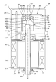
- FIG. 2 is a longitudinal sectional view of the motor control device 19 according to the first embodiment.
- the motor control device 19 is an electromechanically integrated motor control device in which an electric motor 11, a control board (power control unit) 20, and a power board (power supply unit) 21 are integrally provided.
- the direction of the rotation axis O of the motor shaft 14 is the x-axis, and the lower side of the paper is the positive direction.
- the scissors housing 22 is formed in a substantially cylindrical shape. Inside the housing 22, there are provided a motor element housing portion 23 for housing the electric motor 11 and a control board housing portion 24 for housing the control board 20 and the power board 21.
- the motor element accommodation portion 23 is provided on the x-axis positive direction side of the control board accommodation portion 24.
- the electric motor 11 is accommodated in the motor element accommodating portion 23.
- the electric motor 11 includes a motor shaft 14, a motor rotor 25, and a motor stator 26.
- the motor shaft 14 is made of an iron-based material.
- the x-axis positive direction side of the motor shaft 14 passes through an opening 28 formed in the front portion 27 of the housing 22 and protrudes from the front portion 27 to the x-axis positive direction side.
- the motor shaft 14 is supported by a pair of ball bearings 29 and 30 so as to be rotatable with respect to the housing 22.
- the ball bearing 29 is supported by the front portion 27.
- the ball bearing 30 is supported by a partition wall (bearing support portion) 31.
- the partition wall 31 is fixed to the side surface portion 32 of the housing 22.
- the partition wall 31 defines a motor element accommodation portion 23 and a control board accommodation portion 24.
- the x-axis negative direction side of the motor shaft 14 passes through an opening 34 formed in the bearing support portion 31 and protrudes from the bearing support portion 31 toward the x-axis negative direction side (motor element housing portion 23 side).
- the motor rotor 25 rotates integrally with the motor shaft 14.
- the motor stator 26 rotates the motor rotor 25 when energized.
- the motor stator 26 is fixed to the side surface portion 32 of the housing 22.
- the motor stator 26 includes a core on which electromagnetic steel sheets are laminated and a coil wound around the core via an insulator.
- the electric motor 11 of the first embodiment is a three-phase brushless motor, and the cores and coils are provided in multiples of the U, V, and W phases.
- control board housing part As described above, the control board 20 and the power board 21 are housed in the control board housing portion 24. The control board 20 and the power board 21 are arranged at the same position in the x-axis direction of the housing 22 via a support member (not shown) fixed to the housing 22. The control board 20 and the power board 21 are electrically connected by means such as wire bonding or a flat cable.
- the control board 20 is mounted with a CPU, a rotation angle sensor 17 and the like constituting the ECU 16, and controls electric power supplied to the motor stator 26 based on each sensor value.
- the rotation angle sensor 17 is mounted on the x-axis positive side surface 35 of the control board 20.
- the rotation axis O of the motor shaft 14 passes through the center of the rotation angle sensor 17.
- the rotation angle sensor 17 is provided at a position facing the magnet 45 that rotates integrally with the motor shaft 14.
- the rotation angle sensor 17 is a magnetic sensor that detects the rotation angle of the motor rotor 25 by detecting a change in the magnitude or direction of the magnetic field of the magnet 45.
- the rotation angle sensor 17 is referred to as a magnetic sensor 17.
- the power board 21 is mounted with a power element (switching element), a capacitor, and the like, and supplies power supplied from the outside to the motor stator 26 via a bus bar (power supply line) 36.
- the bus bar 36 is provided for each of the U, V, and W phases, and is connected to a coil for each phase.
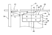
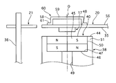
- FIG. 3 is a longitudinal sectional view of the magnet holder (magnet side shielding member) 38 of the first embodiment.
- a magnet holder 38 is provided on the end 37 of the negative side of the motor shaft 14 in the x-axis direction.
- the magnet holder 38 is formed in a cylindrical shape using the same iron-based material as the motor shaft 14.
- the magnet holder 38 has a shaft fixing hole 39 and a magnet housing recess 40.
- the shaft fixing hole 39 extends from the x-axis positive direction side end face 41 of the magnet holder 38 toward the x-axis negative direction side.
- the center of the shaft fixing hole 39 coincides with the center of the magnet holder 38, that is, the rotation axis O of the motor shaft 14.
- An end 37 of the x-axis negative direction of the motor shaft 14 is fixed to the shaft fixing hole 39 by press fitting.
- the x-axis negative direction side edge 42 of the motor shaft 14 is in contact with the bottom 43 of the shaft fixing hole 39.
- the magnet housing recess 40 extends from the x-axis negative direction side end surface 44 of the magnet holder 38 toward the x-axis positive direction side.
- the center of the magnet housing recess 40 coincides with the center of the magnet holder 38.
- a magnet 45 is attached to the magnet housing recess 40 using, for example, an adhesive.
- the x-axis positive direction edge 46 of the magnet 45 is in contact with the bottom 47 of the magnet housing recess 40.
- the bottom 47 surrounds the end of the magnet 45 in the positive x-axis direction.
- the side surface 50 of the magnet 45 is surrounded by the side surface 51 of the magnet housing recess 40.
- the x-axis negative direction end edge 48 of the magnet 45 and the x-axis negative direction side end face 44 of the side surface 51 of the magnet holder 38 have the same position in the x-axis direction.
- a through hole 49 is provided between the shaft fixing hole 39 and the magnet housing recess 40. The through hole 49 is set to have a smaller diameter than the shaft fixing hole 39.
- the magnet 45 is a double-sided, four-pole cylindrical magnet having an N pole and an S pole at positions facing each other across the rotation axis O of the motor shaft 14.
- the N pole and S pole of the magnet 45 are formed, for example, by using a magnetizing yoke and being magnetized by a magnetic field generated in the direction of the rotation axis O of the motor shaft 14.
- the magnet holder 38 is set so that the shortest distance L 1 between the bus bar 36 and the magnetic sensor 17 is larger than the shortest distance L 2 between the bus bar 36 and the magnet holder 38. Further, the magnet holder 38 has a distance L 3 between the position of the bus bar 36 where the distance between the bus bar 36 and the magnetic sensor 17 is the shortest distance L 1 and the magnet holder 38, and the magnet holder 38 and the magnetic sensor 17 It is set to be larger than the shortest distance L 4 between.
- a magnet holder 38 made of a magnetic material that rotates integrally with the magnet 45 is provided on the outer peripheral side of the magnet 45.
- the magnet holder 38 absorbs the magnetic field generated from the bus bar 36, so that the influence of the magnetic field from the bus bar 36 on the magnetic field generated by the magnet 45 can be suppressed. Thereby, the detection accuracy of the magnetic sensor 17 can be improved.
- the N pole and S pole of the magnet 45 are formed by being magnetized by a magnetic field generated in the direction of the rotation axis O of the motor shaft 14 (x-axis direction). That is, the magnet 45 is magnetized in the x-axis direction.
- the outer periphery of the magnet 45 is surrounded by a magnet holder 38 made of a magnetic material.
- the magnet 45 is magnetized in a direction (radial direction) perpendicular to the x axis.
- the magnetic field of the magnet 45 is mainly generated from the outer peripheral side of the magnet 45.
- the magnet holder 38 since most of the generated magnetic field is absorbed by the magnet holder 38, the magnetic field generated by the magnet 45 is reduced, and the detection accuracy of the magnetic sensor 17 is reduced.
- the magnet 45 when the magnet 45 is magnetized in the x-axis direction, the magnetic field of the magnet 45 is mainly generated from the side facing the magnetic sensor 17, so the magnet holder 38 is compared with the case of radial magnetization. Can reduce the magnetic field absorbed. That is, a decrease in the magnetic field generated by the magnet 45 due to the outer periphery of the magnet 45 being surrounded by the magnet holder 38 made of a magnetic material can be suppressed.
- the magnet holder 38 is provided such that the shortest distance L 1 between the bus bar 36 and the magnetic sensor 17 is larger than the shortest distance L 2 between the bus bar 36 and the magnet holder 38. That is, by providing the magnet holder 38 so that L 1 > L 2 , the magnetic field from the bus bar 36 is absorbed first by the magnet holder 38 closer to the magnetic sensor 17, so that the bus bar reaching the magnetic sensor 17 is reached. The magnetic field from 36 can be suppressed.
- the magnet holder 38 has a distance L 3 between the position of the bus bar 36 where the distance between the bus bar 36 and the magnetic sensor 17 is the shortest distance L 1 and the magnet holder 38, and the magnet holder 38 and the magnetic sensor 17 It provided to be larger than the shortest distance L 4 between. That is, by making the distance L 4 between the magnet holder 38 and the magnetic sensor 17 sufficiently small, the influence of the magnetic field from the bus bar 36 entering through the gap between the magnet holder 38 and the magnetic sensor 17 can be suppressed.
- the magnet holder 38 has a bottom 47 that surrounds the x-axis positive direction edge 46 of the magnet 45.
- the magnet holder 38 has a side surface 51 provided so as to surround the entire region of the magnet 45 in the x-axis direction.
- the magnet holder 38 of the first embodiment Since the magnet holder 38 of the first embodiment is made of a magnetic material, it may be magnetized by the magnet 45. However, since the magnet holder 38 of the first embodiment rotates integrally with the magnet 45 when the motor is driven, the phase of the magnetic field generated from the magnet holder 38 always matches the phase of the magnetic field generated from the magnet 45. That is, since the influence on the detection accuracy of the magnetic sensor 17 when the magnet holder 38 is magnetized is small, a decrease in the detection accuracy of the magnetic sensor 17 can be suppressed.
- the magnet holder 38 has a magnet housing recess 40 for housing the magnet 45. Therefore, since the magnet holder 38 itself has the magnet housing recess 40, it is not necessary to separately provide a magnet fixing member, and an increase in the number of parts can be suppressed.
- the magnet holder 38 has a shaft fixing hole 39 provided in the bottom 47, and the motor shaft 14 is press-fitted into the shaft fixing hole 39 to fix the magnet holder 38 to the motor shaft 14. Therefore, by directly fixing the magnet holder 38 and the motor shaft 14 by press-fitting, there is no need to separately provide a coupling member, and the number of parts can be reduced.
- a through hole 49 having a smaller diameter than the shaft fixing hole 39 is provided between the magnet housing recess 40 and the shaft fixing hole 39.
- the magnet holder 38 and the motor shaft 14 are formed of the same iron-based material. That is, since the linear expansion coefficients of the magnet holder 38 and the motor shaft 14 are the same, the deformation amounts with respect to the temperature change of both are almost the same. Therefore, it is possible to prevent a reduction in interference due to a temperature change and to suppress loosening of press-fitting of the motor shaft 14 into the magnet holder 38.
- the detection accuracy of the magnetic sensor 17 is improved by providing the magnet holder 38 made of a magnetic material that rotates integrally with the magnet 45 on the outer peripheral side of the magnet 45. Is realized.
- the controllability of the electric motor 11 can be improved. Thereby, the steering assist force applied to the steering mechanism 1 becomes smooth, and the steering feel can be improved.
- Example 1 has the following effects.
- a housing 22 having a motor element housing portion 23 and a control board housing portion 24, a motor shaft 14 provided in the motor element housing portion 23 and supported rotatably, and the motor shaft 14 rotating integrally.
- the motor rotor 25 provided in the motor element accommodating portion 23, the motor stator 26 provided in the motor element accommodating portion 23 for rotating the motor rotor 25 when energized, and the control board accommodating portion 24 are provided.
- the magnet 45 is provided on the control board housing part 24 side and has an N pole and an S pole at positions facing each other across the rotation axis O of the motor shaft 14, and in the control board housing part 24, Magnet that detects the rotation angle of the motor rotor 25 that rotates integrally with the motor shaft 14 by detecting a change in the magnitude or direction of the magnetic field of the magnet 45 as the motor shaft 14 rotates.
- the sensor 17, the control board 20 that is provided in the control board housing part 24 and controls the power supplied from the bus bar 36 to the motor stator 26 based on the rotation angle of the motor rotor 25, and the rotation axis O of the motor shaft 14 as a reference.
- the magnet holder 38 is formed on the outer peripheral side of the magnet 45 so as to rotate integrally with the magnet 45 and is made of a magnetic material. Therefore, since the influence of the magnetic field from the bus bar 36 on the magnetic field generated by the magnet 45 can be suppressed, the detection accuracy of the magnetic sensor 17 can be improved. Further, the influence on the detection accuracy of the magnetic sensor 17 when the magnet holder 38 is magnetized can be reduced, and a decrease in the detection accuracy of the magnetic sensor 17 can be suppressed.
- the N pole and S pole of the magnet 45 are formed by being magnetized by a magnetic field generated in the direction of the rotation axis O of the motor shaft 14. Therefore, it is possible to suppress a decrease in the generated magnetic field of the magnet 45 due to the outer periphery of the magnet 45 being surrounded by the magnet holder 38 made of a magnetic material.
- the magnet holder 38 is provided such that the shortest distance L 1 between the bus bar 36 and the magnetic sensor 17 is larger than the shortest distance L 2 between the bus bar 36 and the magnet holder 38. Therefore, the magnetic field from the bus bar 36 reaching the magnetic sensor 17 can be suppressed.
- the magnet holder 38 is provided such that the distance L 3 between the bus bar 36 and the magnet holder 38 is larger than the distance L 4 between the magnet holder 38 and the magnetic sensor 17. Therefore, the influence of the magnetic field from the bus bar 36 entering from between the magnet holder 38 and the magnetic sensor 17 can be suppressed.
- the magnet holder 38 has a bottom 47 that surrounds the end on the motor shaft side of both ends of the magnet 45 in the axial direction. Therefore, the influence of the magnetic field from the bus bar 36 on the motor shaft 14 side of the magnet 45 can be suppressed.
- the magnet holder 38 has a magnet housing recess 40 for housing the magnet 45. Therefore, there is no need to provide a separate magnet fixing member, and the number of parts can be reduced.
- a steering mechanism 1 that steers the steered wheels as the steering wheel 2 rotates, a housing 22 that includes a motor element housing portion 23 and a control board housing portion 24, and a rotation provided in the motor element housing portion 23.
- a motor shaft 14 that is freely supported, a motor rotor 25 that is provided in the motor element accommodating portion 23 so as to rotate integrally with the motor shaft 14, and a motor rotor that is provided in the motor element accommodating portion 23 and is energized.
- the motor stator 26 that rotates the motor 25, the power board 21 that is provided in the control board housing 24 and supplies power to the motor stator, and the motor stator 26 and the power board 21 are connected to each other.
- a magnetic sensor 17 that detects a rotation angle of a motor rotor 25 that rotates integrally with the motor shaft 14 by detecting a change, and a control board housing portion 24 are provided.
- the steering assist force applied to the steering mechanism 1 becomes smooth, and the steering feel can be improved.
- FIG. 4 is a longitudinal sectional view of the magnet holder 52 of the second embodiment.
- the x axis negative direction side end surface 53 of the side surface 51 is in the x axis negative direction more than the x axis negative direction side edge 48 of the magnet 45. It differs from the first embodiment in that it protrudes to the side.
- the end surface 53 of the side surface 51 on the x-axis negative direction side protrudes from the x-axis negative direction side edge 48 of the magnet 45 toward the x-axis negative direction side, that is, the magnetic sensor 17 side.
- the clearance gap between the magnet holder 38 and the magnetic sensor 17 can be made small, the influence of the magnetic field from the bus-bar 36 can further be suppressed.
- the magnet holder 52 has a shaft fixing hole 39 for fixing the magnet holder 52 to the motor shaft 14 when the motor shaft 14 is press-fitted. Therefore, similarly to the first embodiment, by directly fixing the magnet holder 38 and the motor shaft 14 by press-fitting, it is not necessary to provide a separate coupling member, and the number of parts can be reduced.
- Example 2 has the following effects in addition to the effects (1) to (7) of Example 1.
- the magnet holder 52 is provided so as to protrude from the x negative direction side edge 48 of the magnet 45 to the x axis negative direction side. Therefore, the influence of the magnetic field from the bus bar 36 can be further suppressed.
- the magnet holder 52 has a shaft fixing hole 39 for fixing the magnet holder 52 to the motor shaft 14 when the motor shaft 14 is press-fitted. Therefore, by directly fixing the magnet holder 52 and the motor shaft 14 by press-fitting, there is no need to separately provide a coupling member, and the number of parts can be reduced. Further, when the motor shaft 14 is press-fitted into the shaft fixing hole 39, the magnet 45 is not directly subjected to a pressing load, so that damage to the magnet 45 during pressing can be suppressed.
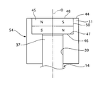
- FIG. 5 is a longitudinal sectional view of the magnet holder 54 of the third embodiment.
- the magnet holder (magnet side shielding member) 54 of the third embodiment eliminates the through hole 49 of the magnet holder 38 of the first embodiment shown in FIG. This embodiment differs from the first embodiment in that it extends to the bottom 47 of the first embodiment.
- Example 3 since it comprised as mentioned above, since the process of creating the through-hole 49 can be omitted, it can contribute to man-hour reduction. In addition, the dimension of the magnet holder 54 in the x-axis direction can be shortened by the amount that the through hole 49 is not provided with respect to the magnet holder 38 of the first embodiment.
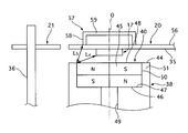
- FIG. 6 is a longitudinal sectional view of the substrate side cover 57 of the fourth embodiment.
- the motor control device 19 according to the fourth embodiment is different from the first embodiment in that a substrate-side cover (substrate-side shielding member) 57 is provided on the x-axis negative direction side surface 56 of the control substrate 20.
- the substrate side cover 57 is disposed so as to overlap the magnetic sensor 17 in a direction orthogonal to the rotation axis O of the motor shaft 14, that is, a direction orthogonal to the x axis.
- the board-side cover 57 is made of a magnetic material and is formed into a bottomed rectangular tube shape in which a soldering portion 58 and a separation portion 59 are integrally molded.
- the soldering portion 58 extends from the x-axis negative direction side surface 56 to the x-axis negative direction side.
- the soldering portion 58 is soldered to the control board 20 at the end on the x-axis positive direction side.
- the separation portion 59 is provided at the end portion on the x-axis negative direction side of the soldering portion 58 and extends in a direction orthogonal to the x-axis.
- the separation portion 59 is separated from the control board 20 in the x-axis direction.
- the substrate side cover 57 is subjected to a plating process in order to improve the wettability of soldering.
- Substrate-side cover 57 and the magnet holder 38 is provided so as shortest distance L 4 between the magnet holder 38 and the magnetic sensor 17 is larger than the shortest distance L 5 between the substrate-side cover 57 and the magnet holder 38 ing.
- a substrate-side cover 57 made of a magnetic material is provided on the opposite side of the control substrate 20 to the magnetic sensor 17 so as to overlap the magnetic sensor 17 in a direction orthogonal to the rotational axis of the motor shaft 14.
- the substrate-side cover 57 absorbs the magnetic field generated from the bus bar 36, so that the influence of the magnetic field from the bus bar 36 on the magnetic field generated by the magnet 45 can be suppressed. Thereby, the detection accuracy of the magnetic sensor 17 can be improved.
- Substrate-side cover 57 and the magnet holder 38 is provided so as shortest distance L 4 between the magnet holder 38 and the magnetic sensor 17 is larger than the shortest distance L 5 between the substrate-side cover 57 and the magnet holder 38 . That is, the shortest distance L 5 between the substrate-side cover 57 and the magnet holder 38 by sufficiently small, from the bus bar 36 entering from the gap to the magnetic sensor 17 side between the substrate-side cover 57 and the magnet holder 38 Can be absorbed by either the substrate-side cover 57 or the magnet holder 38.
- the substrate side cover 57 of the fourth embodiment is made of a magnetic material, it may be magnetized by the magnet 45. However, since the substrate-side cover 57 of the fourth embodiment has the separating portion 59 that is separated from the control substrate 20 in the x-axis direction, the influence on the magnetic sensor 17 when the substrate-side cover 57 is magnetized can be suppressed.
- the board side cover 57 is soldered to the control board 20. Thereby, the board side cover 57 can be easily fixed to the control board 20.
- the board-side cover 57 includes a separation part 59 that is separated from the control board 20 in the direction of the rotation axis O of the motor shaft 14, and a soldering part 58 that is integrally formed with the separation part 59 and soldered to the control board 20. . Therefore, the number of parts can be reduced as compared with the case where the soldering portion 58 and the separation portion 59 are provided separately.
- Example 4 has the following effects in addition to the effects (1) to (7) of Example 1.
- a housing 22 having a motor element accommodating portion 23 and a control board accommodating portion 24, a motor shaft 14 provided in the motor element accommodating portion 23 and rotatably supported, and rotates integrally with the motor shaft 14.
- the motor rotor 25 provided in the motor element accommodating portion 23, the motor stator 26 provided in the motor element accommodating portion 23 for rotating the motor rotor 25 when energized, and the control board accommodating portion 24 are provided.
- a pair of a power board 21 for supplying electric power to the motor stator 26, a bus bar 36 for connecting the motor stator 26 and the power board 21, and supplying electric power from the power board 21 to the motor stator 26, and a motor shaft 14 are provided on the control board housing part 24 side, and have a magnet 45 having N and S poles at positions facing each other across the rotation axis O of the motor shaft 14, and the rotation axis O of the motor shaft 14.
- the magnitude of the magnetic field of the magnet 45 associated with the rotation of the motor shaft 14 is provided on the control board 20 so as to directly face the magnet 45 and the control board 20 provided in the control board housing portion 24 so as to be substantially orthogonal.
- a magnetic sensor 17 that detects the rotation angle of the motor rotor 25 that rotates integrally with the motor shaft 14 by detecting a change in the height or direction, and a control board 20, provided from the power board 21 based on the rotation angle of the motor rotor 25.
- the ECU 16 that controls the electric power supplied to the motor stator 26 and the magnetic sensor 17 on the opposite side of the control board 20 are provided so as to overlap the magnetic sensor 17 in a direction perpendicular to the rotation axis of the motor shaft 14. And a substrate side cover 57 formed of a magnetic material. Therefore, since the influence of the magnetic field from the bus bar 36 on the magnetic field generated by the magnet 45 can be suppressed, the detection accuracy of the magnetic sensor 17 can be improved.
- FIG. 7 is a longitudinal sectional view of the substrate side cover 60 of the fifth embodiment.
- the board-side cover (board-side shielding member) 60 is provided with a flange portion 61 extending in the direction orthogonal to the x-axis at the end of the soldering portion 58 on the x-axis positive direction side. This is different from the fourth embodiment.
- the flange-side cover 61 is soldered to the control board 20 at the flange-side cover 60.
- Example 5 since it was configured as described above, the bonding area with the control substrate 20 can be increased. Therefore, the coupling force with the control board 20 can be improved and the soldering operation can be facilitated.
- the magnet holder 52 of the second embodiment may be applied to the configurations of the third to fifth embodiments.
- the magnet holder 54 of the third embodiment may be applied to the configurations of the fourth to fifth embodiments.
- the motor control device wherein the magnet side shielding member is provided so as to surround the entire region of the magnet in the axial direction when the direction of the rotation axis of the motor shaft is an axial direction. Therefore, the influence of the magnetic field from the power supply line can be suppressed in the entire axial direction of the magnet.
- the said magnet side shielding member is a motor control apparatus provided so that it may protrude rather than the edge part by the side of the said magnetic sensor among the said axial direction both ends of the said magnet. Therefore, the influence of the magnetic field from the power supply line can be further suppressed.
- the magnet-side shielding member has a shaft fixing hole for fixing the magnet-side shielding member to the motor shaft when the motor shaft is press-fitted. Therefore, by directly fixing the magnet-side shielding member and the motor shaft by press-fitting, it is not necessary to separately provide a coupling member, and an increase in the number of parts can be suppressed.
- the motor shaft is press-fitted into the shaft fixing hole, since the magnet is not directly subjected to the pressing load, damage to the magnet during pressing can be suppressed.
- the magnet-side shielding member has a shaft fixing hole that is provided at the bottom portion and fixes the magnet-side shielding member to the motor shaft when the motor shaft is press-fitted. Therefore, by directly fixing the magnet-side shielding member and the motor shaft by press-fitting, there is no need to separately provide a coupling member, so that an increase in the number of parts can be suppressed.
- substrate side shielding member is a motor control apparatus which has a separation part spaced apart from the said control board in the direction of the rotating shaft of the said motor shaft. Therefore, the influence on the magnetic sensor by the magnetic field generated from the substrate side shielding member when the substrate side shielding member is magnetized can be suppressed.
- the rotation axis of the motor shaft When the rotation axis of the motor shaft is used as a reference, it is provided on the outer peripheral side of the magnet so as to rotate integrally with the magnet, and has a magnet side shielding member formed of a magnetic material, The substrate-side shielding member and the magnet-side shielding member are arranged such that the shortest distance between the magnet-side shielding member and the magnetic sensor is greater than the shortest distance between the substrate-side shielding member and the magnet-side shielding member.
- a motor control device is provided. Therefore, the magnetic field from the power supply line entering the magnetic sensor side through the gap between the substrate side shielding member and the magnet side shielding member by sufficiently reducing the distance between the substrate side shielding member and the magnet side shielding member. Can be absorbed by either the substrate-side shielding member or the magnet-side shielding member.
- the board-side shielding member is soldered to the control board. Therefore, the board side shielding member can be easily fixed to the control board.
- the board-side shielding member includes a separation part that is separated from the control board in the direction of the rotation axis of the motor shaft, and a soldering part that is integrally formed with the separation part and is soldered to the control board. Motor control device. Therefore, the number of parts can be reduced by integrally molding the separation portion and the soldering portion.
- the substrate-side shielding member is a motor control device that is subjected to a plating process to improve solder wettability. Therefore, the bonding force of the board-side shielding member can be improved by performing a plating process that improves the wettability of soldering.
- the magnet side shielding member is provided such that a shortest distance between the power supply line and the magnetic sensor is larger than a shortest distance between the power supply line and the magnet side shielding member. apparatus. Therefore, since the magnetic field from the power supply line is first absorbed by the magnet-side shielding member closer to the magnetic sensor, the magnetic field from the power supply line reaching the magnetic sensor can be suppressed.
- the power steering apparatus wherein the magnet side shielding member is provided such that a distance between the power supply line and the magnet side shielding member is larger than a distance between the magnet side shielding member and the magnetic sensor. Therefore, by sufficiently reducing the distance between the magnet side shielding member and the magnetic sensor, the influence of the magnetic field from the power supply line entering from between the magnet side shielding member and the magnetic sensor can be suppressed.
- Patent Document 1 The entire disclosure including the specification, claims, drawings and abstract of JP 2008-219996 A (Patent Document 1) is incorporated herein by reference in its entirety.
- Steering mechanism 2 Steering wheel 3 Front wheel (steered wheel) 10 Reducer 14 Motor shaft 16 ECU (microcomputer) 17 Rotation angle sensor (magnetic sensor) 20 Control board (power control part) 21 Power board (power supply part) 22 Housing 23 Motor element housing part 24 Control board housing part 25 Motor rotor 26 Motor stator 36 Bus bar (power supply line) 38 Magnet holder (magnet side shielding member) 45 Magnet 52 Magnet holder (magnet side shielding member) 54 Magnet holder (magnet side shielding member) ) 57 substrate side cover (substrate side shielding member) 60 substrate side cover (substrate side shielding member)
Landscapes
- Engineering & Computer Science (AREA)
- Power Engineering (AREA)
- Microelectronics & Electronic Packaging (AREA)
- Physics & Mathematics (AREA)
- Electromagnetism (AREA)
- Chemical & Material Sciences (AREA)
- Combustion & Propulsion (AREA)
- Transportation (AREA)
- Mechanical Engineering (AREA)
Abstract
Description
図1は、実施例1の電動パワーステアリング装置の構成図である。
モータ要素収容部23には、上述したように、電動モータ11が収容されている。電動モータ11は、モータシャフト14と、モータロータ25と、モータステータ26とから構成される。モータシャフト14は、鉄系材料で形成されている。モータシャフト14のx軸正方向側は、ハウジング22の正面部27に形成された開口部28を貫通し、正面部27よりもx軸正方向側へ突出している。モータシャフト14は、1対のボールベアリング29,30によりハウジング22に対し回動可能に支持されている支持されている。ボールベアリング29は、正面部27に支持されている。ボールベアリング30は、隔壁(ベアリング支持部)31に支持されている。隔壁31は、ハウジング22の側面部32に固定されている。隔壁31により、モータ要素収容部23と制御基板収容部24とが画成されている。モータシャフト14のx軸負方向側は、ベアリング支持部31に形成された開口部34を貫通し、ベアリング支持部31よりもx軸負方向側(モータ要素収容部23側)へ突出している。
制御基板収容部24には、上述したように、制御基板20とパワー基板21とが収容されている。制御基板20およびパワー基板21は、ハウジング22に固定された図外の支持部材を介してハウジング22のx軸方向同一位置に配置されている。制御基板20とパワー基板21とは、例えばワイヤボンディングやフラットケーブル等の手段により電気的に接続されている。
図3は、実施例1のマグネットホルダ(マグネット側遮蔽部材)38の縦断面図である。
実施例1では、マグネット45の外周側に、マグネット45と一体に回転する磁性材料製のマグネットホルダ38を設けた。バスバー36に大電流が流れたとき、マグネットホルダ38はバスバー36から発生する磁界を吸収するため、マグネット45が発生する磁界に対するバスバー36からの磁界の影響を抑制できる。これにより、磁気センサ17の検出精度を向上できる。
実施例1のマグネットホルダ38は磁性材料で形成されているため、マグネット45により磁化される可能性がある。しかしながら、実施例1のマグネットホルダ38は、モータ駆動時にマグネット45と一体に回転するため、マグネットホルダ38から発生する磁界の位相は、マグネット45から発生する磁界の位相と常に一致している。つまり、マグネットホルダ38が磁化された際の磁気センサ17の検出精度に与える影響が小さいため、磁気センサ17の検出精度の低下を抑制できる。
マグネットホルダ38は、マグネット45を収容するマグネット収容凹部40を有する。よって、マグネットホルダ38自身がマグネット収容凹部40を有する構成としたことにより、別途マグネット固定部材を設ける必要が無く、部品点数増を抑制できる。
マグネットホルダ38には、マグネット収容凹部40とシャフト固定孔39との間に、シャフト固定孔39よりも小径の貫通孔49が設けられている。マグネットホルダ38にモータシャフト14を圧入する際は、モータシャフト14のx軸負方向側端縁42は、シャフト固定孔39の底部43と突き当て状態となる。つまり、モータシャフト14とマグネット45との接触を回避でき、マグネット45が直接押圧荷重を受けないため、押圧時のマグネット45の損傷を抑制できる。
マグネットホルダ38およびモータシャフト14は同一の鉄系材料によって形成される。つまり、マグネットホルダ38とモータシャフト14の線膨張係数が同一であるため、両者の温度変化に対する変形量はほぼ一致する。よって、温度変化に伴うしめしろの減少を防ぎ、モータシャフト14のマグネットホルダ38への圧入が緩むのを抑制できる。
上述したように、実施例1のモータ制御装置19では、マグネット45の外周側に、マグネット45と一体に回転する磁性材料製のマグネットホルダ38を設けたことにより、磁気センサ17の検出精度の向上を実現している。この結果、磁気センサ17の検出値(モータ回転角)を用いて電動モータ11を制御する電動パワーステアリング装置において、電動モータ11の制御性を向上できる。これにより、操舵機構1に付与される操舵補助力が滑らかとなり、操舵フィールを向上できる。
よって、マグネット45が発生する磁界に対するバスバー36からの磁界の影響を抑制できるため、磁気センサ17の検出精度を向上できる。
また、マグネットホルダ38が磁化された際の磁気センサ17の検出精度に与える影響を小さくでき、磁気センサ17の検出精度の低下を抑制できる。
よって、マグネット45の外周側を磁性材料製のマグネットホルダ38で包囲したことによるマグネット45の発生磁界の低下を抑制できる。
よって、磁気センサ17に到達するバスバー36からの磁界を抑制できる。
よって、マグネットホルダ38と磁気センサ17の間から入り込むバスバー36からの磁界の影響を抑制できる。
よって、マグネット45のモータシャフト14側におけるバスバー36からの磁界の影響を抑制できる。
よって、別途マグネット固定部材を設ける必要が無いため、部品点数を削減できる。
よって、マグネット45が発生する磁界に対するバスバー36からの磁界の影響を抑制できるため、磁気センサ17の検出精度を向上できる。
また、マグネットホルダ38が磁化された際の磁気センサ17の検出精度に与える影響が小さいため、磁気センサ17の検出精度の低下を抑制できる。
さらに、電動モータ11の制御性を向上できる結果、操舵機構1に付与される操舵補助力が滑らかとなり、操舵フィールを向上できる。
図4は、実施例2のマグネットホルダ52の縦断面図である。
実施例2のマグネットホルダ52は、側面51のx軸負方向側端面53がマグネット45のx軸負方向側端縁48よりもx軸負方向側、すなわち、磁気センサ17側へ突出している。このため、実施例1の場合と比較して、マグネットホルダ38と磁気センサ17との間の隙間を小さくできるため、バスバー36からの磁界の影響をさらに抑制できる。
マグネットホルダ52は、モータシャフト14が圧入されることによりマグネットホルダ52をモータシャフト14に固定するシャフト固定孔39を有する。よって、実施例1と同様に、マグネットホルダ38とモータシャフト14とを直接、圧入により固定することにより、別途、結合部材を設ける必要が無く、部品点数を削減できる。
モータシャフト14をシャフト固定孔39に圧入する際は、マグネット45よりも突出するように形成されたマグネットホルダ52のx軸負方向側端面53を押圧することで、マグネット45が直接押圧荷重を受けないため、押圧時におけるマグネット45の損傷を抑制できる。
よって、バスバー36からの磁界の影響をさらに抑制できる。
よって、マグネットホルダ52とモータシャフト14とを直接、圧入により固定することにより、別途、結合部材を設ける必要が無く、部品点数を削減できる。
また、モータシャフト14をシャフト固定孔39に圧入する際は、マグネット45が直接押圧荷重を受けないため、押圧時におけるマグネット45の損傷を抑制できる。
図5は、実施例3のマグネットホルダ54の縦断面図である。
図6は、実施例4の基板側カバー57の縦断面図である。
実施例4では、制御基板20の磁気センサ17の反対側に、モータシャフト14の回転軸と直交する方向において磁気センサ17とオーバーラップするように設けられ、磁性材料で形成された基板側カバー57を設けた。バスバー36に大電流が流れたとき、基板側カバー57はバスバー36から発生する磁界を吸収するため、マグネット45が発生する磁界に対するバスバー36からの磁界の影響を抑制できる。これにより、磁気センサ17の検出精度を向上できる。
実施例4の基板側カバー57は磁性材料で形成されているため、マグネット45により磁化される可能性がある。しかしながら、実施例4の基板側カバー57は、x軸方向において制御基板20と離間する離間部59を有するため、基板側カバー57が磁化された際の磁気センサ17に与える影響を抑制できる。
基板側カバー57は、制御基板20に半田付けされる。これにより、基板側カバー57を容易に制御基板20に固定できる。
基板側カバー57は、モータシャフト14の回転軸Oの方向において制御基板20と離間する離間部59と、離間部59と一体成型され、制御基板20に半田付けされる半田付け部58とを有する。よって、半田付け部58と離間部59とを個別に設ける場合と比較して、部品点数を削減できる。
基板側カバー57は、半田付けの濡れ性を向上させるメッキ処理が施されているため、制御基板20との結合力を向上できる。
よって、マグネット45が発生する磁界に対するバスバー36からの磁界の影響を抑制できるため、磁気センサ17の検出精度を向上できる。
図7は、実施例5の基板側カバー60の縦断面図である。
以上、本発明を実施するための形態を、実施例に基づいて説明したが、本発明の具体的な構成は、実施例に示した構成に限定されるものではなく、発明の要旨を逸脱しない範囲の設計変更等があっても本発明に含まれる。
前記モータシャフトの回転軸の方向を軸方向としたとき、前記マグネット側遮蔽部材は、前記マグネットの前記軸方向全域を包囲するように設けられる、モータ制御装置。
よって、マグネットの軸方向全域において電力供給線からの磁界の影響を抑制できる。
前記マグネット側遮蔽部材は、前記マグネットの前記軸方向両端部のうち前記磁気センサ側の端部よりも突出するように設けられる、モータ制御装置。
よって、電力供給線からの磁界の影響をさらに抑制できる。
前記マグネット側遮蔽部材は、前記モータシャフトが圧入されることにより前記マグネット側遮蔽部材を前記モータシャフトに固定するシャフト固定孔を有する、モータ制御装置。
よって、マグネット側遮蔽部材とモータシャフトとを直接、圧入により固定することにより、別途、結合部材を設ける必要が無く、部品点数増を抑制できる。
モータシャフトをシャフト固定孔に圧入する際は、マグネットが直接押圧荷重を受けないため、押圧時におけるマグネットの損傷を抑制できる。
前記マグネット側遮蔽部材は、前記底部に設けられ、前記モータシャフトが圧入されることにより前記マグネット側遮蔽部材を前記モータシャフトに固定するシャフト固定孔を有することを特徴とするモータ制御装置。
よって、マグネット側遮蔽部材とモータシャフトとを直接、圧入により固定することにより、別途、結合部材を設ける必要が無いため、部品点数増を抑制できる。
前記マグネット側遮蔽部材および前記モータシャフトは鉄系材料によって形成される、モータ制御装置。
よって、マグネット側遮蔽部材とモータシャフトが共に鉄系材料で形成され、線膨張係数が同じかまたは近いため、モータシャフトのマグネット側遮蔽部材への圧入が緩むのを抑制できる。
前記基板側遮蔽部材は、前記モータシャフトの回転軸の方向において前記制御基板と離間する離間部を有する、モータ制御装置。
よって、基板側遮蔽部材が磁化された場合の基板側遮蔽部材から発生する磁界による磁気センサへの影響を抑制することができる。
前記モータシャフトの回転軸を基準としたとき、前記マグネットの外周側であって、前記マグネットと一体に回転するように設けられ、磁性材料で形成されたマグネット側遮蔽部材を有し、
前記基板側遮蔽部材および前記マグネット側遮蔽部材は、前記マグネット側遮蔽部材と前記磁気センサの間の最短距離が前記基板側遮蔽部材と前記マグネット側遮蔽部材の間の最短距離よりも大きくなるように設けられる、モータ制御装置。
よって、基板側遮蔽部材とマグネット側遮蔽部材の間の距離を十分小さくすることにより、基板側遮蔽部材とマグネット側遮蔽部材の間の隙間を介して磁気センサ側へ侵入する電力供給線からの磁界を基板側遮蔽部材とマグネット側遮蔽部材のどちらかで吸収できる。
よって、基板側遮蔽部材を容易に制御基板に固定できる。
前記基板側遮蔽部材は、前記モータシャフトの回転軸の方向において前記制御基板と離間する離間部と、前記離間部と一体成型され、前記制御基板に半田付けされる半田付け部と、を有する、モータ制御装置。
よって、離間部と半田付け部を一体成型したことにより、部品点数の削減を図ることができる。
前記基板側遮蔽部材は、半田付けの濡れ性を向上させるメッキ処理が施される、モータ制御装置。
よって、半田付けの濡れ性を向上させるメッキ処理を施すことにより、基板側遮蔽部材の結合力を向上できる。
前記マグネット側遮蔽部材は、前記電力供給線と前記磁気センサとの間の最短距離が、前記電力供給線と前記マグネット側遮蔽部材との間の最短距離よりも大きくなるように設けられる、パワーステアリング装置。
よって、電力供給線からの磁界は、磁気センサよりも近いマグネット側遮蔽部材に先に吸収されるため、磁気センサに到達する電力供給線からの磁界を抑制できる。
前記マグネット側遮蔽部材は、前記電力供給線と前記マグネット側遮蔽部材との距離が、前記マグネット側遮蔽部材と前記磁気センサとの距離よりも大きくなるように設けられる、パワーステアリング装置。
よって、マグネット側遮蔽部材と磁気センサとの間の距離を十分に小さくすることで、マグネット側遮蔽部材と磁気センサの間から入り込む電力供給線からの磁界の影響を抑制できる。
Claims (20)
- モータ要素収容部と制御基板収容部と、を有するハウジングと、
前記モータ要素収容部内に設けられ回転自在に支持されたモータシャフトと、
前記モータシャフトと一体に回転するように前記モータ要素収容部内に設けられたモータロータと、
前記モータ要素収容部内に設けられ、通電されることにより前記モータロータを回転駆動させるモータステータと、
前記制御基板収容部内に設けられ、前記モータステータに電力を供給する電力供給部と、
前記モータステータと前記電力供給部とを接続し、前記電力供給部からの電力を前記モータステータに供給する電力供給線と、
前記モータシャフトの1対の端部のうち、前記制御基板収容部側に設けられ、前記モータシャフトの回転軸を挟んで対向する位置にN極とS極を有するマグネットと、
前記制御基板収容部内であって、前記マグネットと対向する位置に設けられ、前記モータシャフトの回転に伴う前記マグネットの磁界の大きさまたは方向の変化を検出することにより前記モータシャフトと一体に回転する前記モータロータの回転角を検出する磁気センサと、
前記制御基板収容部内に設けられ、前記モータロータの回転角に基づき前記電力供給部から前記モータステータに供給される電力を制御する電力制御部と、
前記モータシャフトの回転軸を基準としたとき、前記マグネットの外周側であって、前記マグネットと一体に回転するように設けられ、磁性材料で形成されたマグネット側遮蔽部材と、
を有するモータ制御装置。 - 請求項1に記載のモータ制御装置において、前記マグネットのN極およびS極は、前記モータシャフトの回転軸の方向に発生する磁界により着磁されることにより形成される、モータ制御装置。
- 請求項2に記載のモータ制御装置において、前記モータシャフトの回転軸の方向を軸方向としたとき、前記マグネット側遮蔽部材は、前記マグネットの前記軸方向全域を包囲するように設けられる、モータ制御装置。
- 請求項3に記載のモータ制御装置において、前記マグネット側遮蔽部材は、前記マグネットの前記軸方向両端部のうち前記磁気センサ側の端部よりも突出するように設けられる、モータ制御装置。
- 請求項4に記載のモータ制御装置において、前記マグネット側遮蔽部材は、前記モータシャフトが圧入されることにより前記マグネット側遮蔽部材を前記モータシャフトに固定するシャフト固定孔を有する、モータ制御装置。
- 請求項1に記載のモータ制御装置において、前記マグネット側遮蔽部材は、前記電力供給線と前記磁気センサとの間の最短距離が、前記電力供給線と前記マグネット側遮蔽部材との間の最短距離よりも大きくなるように設けられる、モータ制御装置。
- 請求項1に記載のモータ制御装置において、前記マグネット側遮蔽部材は、前記電力供給線と前記マグネット側遮蔽部材との距離が、前記マグネット側遮蔽部材と前記磁気センサとの距離よりも大きくなるように設けられる、モータ制御装置。
- 請求項1に記載のモータ制御装置において、前記モータシャフトの回転軸の方向を軸方向としたとき、前記マグネット側遮蔽部材は、前記マグネットの前記軸方向両端部のうち前記モータシャフト側の端部を包囲する底部を有する、モータ制御装置。
- 請求項8に記載のモータ制御装置において、前記マグネット側遮蔽部材は、前記マグネットを収容するマグネット収容凹部を有する、モータ制御装置。
- 請求項9に記載のモータ制御装置において、前記マグネット側遮蔽部材は、前記底部に設けられ、前記モータシャフトが圧入されることにより前記マグネット側遮蔽部材を前記モータシャフトに固定するシャフト固定孔を有する、モータ制御装置。
- 請求項10に記載のモータ制御装置において、前記マグネット側遮蔽部材および前記モータシャフトは鉄系材料によって形成される、モータ制御装置。
- モータ要素収容部と制御基板収容部と、を有するハウジングと、
前記モータ要素収容部内に設けられ回転自在に支持されたモータシャフトと、
前記モータシャフトと一体に回転するように前記モータ要素収容部内に設けられたモータロータと、
前記モータ要素収容部内に設けられ、通電されることにより前記モータロータを回転駆動させるモータステータと、
前記制御基板収容部内に設けられ、前記モータステータに電力を供給する電力供給部と、
前記モータステータと前記電力供給部とを接続し、前記電力供給部からの電力を前記モータステータに供給する電力供給線と、
前記モータシャフトの1対の端部のうち、前記制御基板収容部側に設けられ、前記モータシャフトの回転軸を挟んで対向する位置にN極とS極を有するマグネットと、
前記モータシャフトの回転軸に対しほぼ直交するように前記制御基板収容部内に設けられた制御基板と、
前記マグネットと直接対向するように前記制御基板上に設けられ、前記モータシャフトの回転に伴う前記マグネットの磁界の大きさまたは方向の変化を検出することにより前記モータシャフトと一体に回転する前記モータロータの回転角を検出する磁気センサと、
前記制御基板上に設けられ、前記モータロータの回転角に基づき前記電力供給部から前記モータステータに供給される電力を制御するマイクロコンピュータと、
前記制御基板の前記磁気センサの反対側であって、前記モータシャフトの回転軸と直交する方向において前記磁気センサとオーバーラップするように設けられ、磁性材料で形成された基板側遮蔽部材と、
を有するモータ制御装置。 - 請求項12に記載のモータ制御装置において、前記基板側遮蔽部材は、前記モータシャフトの回転軸の方向において前記制御基板と離間する離間部を有する、モータ制御装置。
- 請求項12に記載のモータ制御装置は、前記モータシャフトの回転軸を基準としたとき、前記マグネットの外周側であって、前記マグネットと一体に回転するように設けられ、磁性材料で形成されたマグネット側遮蔽部材を有し、
前記基板側遮蔽部材および前記マグネット側遮蔽部材は、前記マグネット側遮蔽部材と前記磁気センサの間の最短距離が前記基板側遮蔽部材と前記マグネット側遮蔽部材の間の最短距離よりも大きくなるように設けられる、モータ制御装置。 - 請求項12に記載のモータ制御装置において、前記基板側遮蔽部材は、前記制御基板に半田付けされる、モータ制御装置。
- 請求項15に記載のモータ制御装置において、前記基板側遮蔽部材は、前記モータシャフトの回転軸の方向において前記制御基板と離間する離間部と、前記離間部と一体成型され、前記制御基板に半田付けされる半田付け部と、を有する、モータ制御装置。
- 請求項15に記載のモータ制御装置において、前記基板側遮蔽部材は、半田付けの濡れ性を向上させるメッキ処理が施される、モータ制御装置。
- ステアリングホイールの回転に伴い転舵輪を転舵させる操舵機構と、
モータ要素収容部と制御基板収容部と、を有するハウジングと、
前記モータ要素収容部内に設けられ回転自在に支持されたモータシャフトと、
前記モータシャフトと一体に回転するように前記モータ要素収容部内に設けられたモータロータと、
前記モータ要素収容部内に設けられ、通電されることにより前記モータロータを回転駆動させるモータステータと、
前記制御基板収容部内に設けられ、前記モータステータに電力を供給する電力供給部と、
前記モータステータと前記電力供給部とを接続し、前記電力供給部からの電力を前記モータステータに供給する電力供給線と、
前記モータシャフトの1対の端部のうち、前記制御基板収容部側に設けられ、前記モータシャフトの回転軸を挟んで対向する位置にN極とS極を有するマグネットと、
前記制御基板収容部内であって、前記マグネットと対向する位置に設けられ、前記モータシャフトの回転に伴う前記マグネットの磁界の大きさまたは方向の変化を検出することにより前記モータシャフトと一体に回転する前記モータロータの回転角を検出する磁気センサと、
前記制御基板収容部内に設けられ、前記モータロータの回転角に基づき前記電力供給部から前記ステータに供給される電力を制御する電力制御部と、
前記モータシャフトの回転軸を基準としたとき、前記マグネットの外周側であって、前記マグネットと一体に回転するように設けられ、磁性材料で形成されたマグネット側遮蔽部材と、
前記モータシャフトと前記操舵機構の間に設けられ、前記モータシャフトからの回転トルクを前記操舵機構に伝達することにより前記操舵機構に操舵力を付与させる減速機と、
を有するパワーステアリング装置。 - 請求項18に記載のパワーステアリング装置において、前記マグネット側遮蔽部材は、前記電力供給線と前記磁気センサとの間の最短距離が、前記電力供給線と前記マグネット側遮蔽部材との間の最短距離よりも大きくなるように設けられる、パワーステアリング装置。
- 請求項18に記載のパワーステアリング装置において、前記マグネット側遮蔽部材は、前記電力供給線と前記マグネット側遮蔽部材との距離が、前記マグネット側遮蔽部材と前記磁気センサとの距離よりも大きくなるように設けられる、パワーステアリング装置。
Priority Applications (4)
| Application Number | Priority Date | Filing Date | Title |
|---|---|---|---|
| CN201580003705.1A CN106104985B (zh) | 2014-02-04 | 2015-01-28 | 马达控制装置及动力转向装置 |
| KR1020167017303A KR101802103B1 (ko) | 2014-02-04 | 2015-01-28 | 모터 제어 장치 및 파워 스티어링 장치 |
| US15/111,257 US10404142B2 (en) | 2014-02-04 | 2015-01-28 | Motor control apparatus and power steering apparatus |
| DE112015000638.9T DE112015000638T5 (de) | 2014-02-04 | 2015-01-28 | Motorsteuerungseinrichtung und Servolenkeinrichtung |
Applications Claiming Priority (2)
| Application Number | Priority Date | Filing Date | Title |
|---|---|---|---|
| JP2014-019085 | 2014-02-04 | ||
| JP2014019085A JP6281688B2 (ja) | 2014-02-04 | 2014-02-04 | モータ制御装置およびパワーステアリング装置 |
Publications (1)
| Publication Number | Publication Date |
|---|---|
| WO2015119002A1 true WO2015119002A1 (ja) | 2015-08-13 |
Family
ID=53777809
Family Applications (1)
| Application Number | Title | Priority Date | Filing Date |
|---|---|---|---|
| PCT/JP2015/052268 Ceased WO2015119002A1 (ja) | 2014-02-04 | 2015-01-28 | モータ制御装置およびパワーステアリング装置 |
Country Status (6)
| Country | Link |
|---|---|
| US (1) | US10404142B2 (ja) |
| JP (1) | JP6281688B2 (ja) |
| KR (1) | KR101802103B1 (ja) |
| CN (1) | CN106104985B (ja) |
| DE (1) | DE112015000638T5 (ja) |
| WO (1) | WO2015119002A1 (ja) |
Cited By (1)
| Publication number | Priority date | Publication date | Assignee | Title |
|---|---|---|---|---|
| JP2017034991A (ja) * | 2015-08-05 | 2017-02-09 | エルジー イノテック カンパニー リミテッド | センサ組立体及びこれを含むモータ |
Families Citing this family (21)
| Publication number | Priority date | Publication date | Assignee | Title |
|---|---|---|---|---|
| JP6455111B2 (ja) * | 2014-12-05 | 2019-01-23 | 株式会社ジェイテクト | 回転角検出装置 |
| JP6710994B2 (ja) * | 2016-02-08 | 2020-06-17 | 株式会社ジェイテクト | 回転角検出装置 |
| US20190248406A1 (en) * | 2016-10-19 | 2019-08-15 | Nsk Ltd. | Assembly structure of sensor, electric motor, and electric power steering device |
| CN108233634B (zh) * | 2016-12-13 | 2024-08-16 | 东兴昌科技(深圳)有限公司 | 可屏蔽干扰的霍尔板 |
| JP7194903B2 (ja) * | 2017-05-30 | 2022-12-23 | パナソニックIpマネジメント株式会社 | 電動工具 |
| DE102017210675A1 (de) * | 2017-06-26 | 2018-12-27 | Bayerische Motoren Werke Aktiengesellschaft | Elektromotorbaugruppe |
| JP6373532B1 (ja) * | 2017-07-14 | 2018-08-15 | 三菱電機株式会社 | 回転電機 |
| JP7027795B2 (ja) * | 2017-10-19 | 2022-03-02 | 株式会社ジェイテクト | モータ装置 |
| EP3706293B1 (en) * | 2017-11-02 | 2023-09-06 | LG Innotek Co., Ltd. | Motor |
| CN108199538B (zh) * | 2018-01-31 | 2024-07-23 | 东兴昌科技(深圳)有限公司 | 一种伺服轮毂电机 |
| JP6525371B1 (ja) * | 2018-03-28 | 2019-06-05 | 三菱電機株式会社 | 回転電機及びそれを用いたエレベータのドア装置 |
| EP3824249B1 (de) * | 2018-07-20 | 2022-08-31 | Fraba B.V. | Drehwinkelmesssystem |
| DE102018218430A1 (de) * | 2018-10-29 | 2020-04-30 | Bühler Motor GmbH | Magnethalter, Sensormagnetbaugruppe, Elektromotor mit einer Sensormagnetbaugruppe und Verfahren zur Herstellung einer Sensormagnetbaugruppe |
| FR3089714B1 (fr) * | 2018-12-11 | 2021-07-30 | Valeo Equip Electr Moteur | Rotor comprenant un détecteur magnétique de paramètre de rotation du rotor |
| KR102741581B1 (ko) * | 2019-03-12 | 2024-12-12 | 에이치엘만도 주식회사 | 모터위치센서 |
| TWI834650B (zh) * | 2019-03-28 | 2024-03-11 | 台灣東電化股份有限公司 | 旋轉角度感測裝置 |
| CN114270144B (zh) | 2019-09-05 | 2024-02-23 | 弗瑞柏私人有限公司 | 旋转角度测量装置、旋转角度测量系统和电机 |
| CN113670189A (zh) * | 2020-05-14 | 2021-11-19 | 台湾东电化股份有限公司 | 旋转角度感测装置 |
| JP2023528502A (ja) * | 2020-06-04 | 2023-07-04 | エルジー イノテック カンパニー リミテッド | モータ |
| US20220209629A1 (en) * | 2020-12-28 | 2022-06-30 | Borgwarmer Inc. | Magnetic shield for position sensor |
| US12341385B2 (en) * | 2022-07-29 | 2025-06-24 | Borgwarner Inc. | Rotary electrical machine with remote position sensor |
Citations (5)
| Publication number | Priority date | Publication date | Assignee | Title |
|---|---|---|---|---|
| JPH09116303A (ja) * | 1995-10-20 | 1997-05-02 | Murata Mfg Co Ltd | 誘電体共振器装置 |
| JP2007282403A (ja) * | 2006-04-07 | 2007-10-25 | Asmo Co Ltd | 着磁方法及び着磁装置 |
| JP2010139351A (ja) * | 2008-12-11 | 2010-06-24 | Tokyo Cosmos Electric Co Ltd | 回転角度センサ |
| JP2011160636A (ja) * | 2010-02-04 | 2011-08-18 | Denso Corp | モータ、及び、これを用いた電動パワーステアリング装置 |
| JP2013007731A (ja) * | 2011-05-20 | 2013-01-10 | Asmo Co Ltd | モータ及び電動パワーステアリング用モータ |
Family Cites Families (14)
| Publication number | Priority date | Publication date | Assignee | Title |
|---|---|---|---|---|
| EP1117155A1 (de) * | 2000-01-14 | 2001-07-18 | Siemens Aktiengesellschaft | Mit einer Platine abgewinkelt mechanisch fixierbare und elektrisch kontaktierbare Steckereinheit |
| JP5093748B2 (ja) * | 2007-03-01 | 2012-12-12 | 日本電産株式会社 | モータ |
| US10320265B2 (en) * | 2009-07-30 | 2019-06-11 | Mitsuba Corporation | Wiper motor |
| JP5287787B2 (ja) * | 2010-04-16 | 2013-09-11 | 株式会社デンソー | 電動装置 |
| JP5375796B2 (ja) * | 2010-11-05 | 2013-12-25 | 株式会社デンソー | 回転角検出装置、および、これを用いた電動パワーステアリング装置 |
| JP5472045B2 (ja) * | 2010-11-08 | 2014-04-16 | 株式会社安川電機 | エンコーダ付モータ及びモータ用エンコーダ |
| KR101758916B1 (ko) * | 2010-12-21 | 2017-07-17 | 엘지이노텍 주식회사 | 조향각 감지유닛을 구비한 eps 모터 |
| US8916999B2 (en) * | 2011-01-01 | 2014-12-23 | Asmo Co., Ltd. | Motors containing segment conductor coils |
| JP5840374B2 (ja) * | 2011-03-31 | 2016-01-06 | オリエンタルモーター株式会社 | アブソリュートエンコーダ装置及びモータ |
| JP5853820B2 (ja) * | 2012-03-29 | 2016-02-09 | 株式会社デンソー | 駆動装置 |
| JP5672507B2 (ja) * | 2012-07-09 | 2015-02-18 | 株式会社デンソー | 回転電機 |
| JP6056482B2 (ja) * | 2013-01-08 | 2017-01-11 | 株式会社ジェイテクト | 回転角センサの異常検出装置 |
| DE102013204436A1 (de) * | 2013-03-14 | 2014-09-18 | Krones Ag | Antrieb für eine Transportvorrichtung, Satz von Antrieben und Verfahren zum Antreiben einer Transportvorrichtung |
| JP6117577B2 (ja) * | 2013-03-15 | 2017-04-19 | 日立オートモティブシステムズ株式会社 | 電子制御装置 |
-
2014
- 2014-02-04 JP JP2014019085A patent/JP6281688B2/ja active Active
-
2015
- 2015-01-28 US US15/111,257 patent/US10404142B2/en active Active
- 2015-01-28 WO PCT/JP2015/052268 patent/WO2015119002A1/ja not_active Ceased
- 2015-01-28 KR KR1020167017303A patent/KR101802103B1/ko not_active Expired - Fee Related
- 2015-01-28 CN CN201580003705.1A patent/CN106104985B/zh active Active
- 2015-01-28 DE DE112015000638.9T patent/DE112015000638T5/de not_active Withdrawn
Patent Citations (5)
| Publication number | Priority date | Publication date | Assignee | Title |
|---|---|---|---|---|
| JPH09116303A (ja) * | 1995-10-20 | 1997-05-02 | Murata Mfg Co Ltd | 誘電体共振器装置 |
| JP2007282403A (ja) * | 2006-04-07 | 2007-10-25 | Asmo Co Ltd | 着磁方法及び着磁装置 |
| JP2010139351A (ja) * | 2008-12-11 | 2010-06-24 | Tokyo Cosmos Electric Co Ltd | 回転角度センサ |
| JP2011160636A (ja) * | 2010-02-04 | 2011-08-18 | Denso Corp | モータ、及び、これを用いた電動パワーステアリング装置 |
| JP2013007731A (ja) * | 2011-05-20 | 2013-01-10 | Asmo Co Ltd | モータ及び電動パワーステアリング用モータ |
Cited By (2)
| Publication number | Priority date | Publication date | Assignee | Title |
|---|---|---|---|---|
| JP2017034991A (ja) * | 2015-08-05 | 2017-02-09 | エルジー イノテック カンパニー リミテッド | センサ組立体及びこれを含むモータ |
| JP7028548B2 (ja) | 2015-08-05 | 2022-03-02 | エルジー イノテック カンパニー リミテッド | センサ組立体及びこれを含むモータ |
Also Published As
| Publication number | Publication date |
|---|---|
| DE112015000638T5 (de) | 2017-01-26 |
| CN106104985B (zh) | 2019-03-05 |
| KR101802103B1 (ko) | 2017-12-28 |
| JP6281688B2 (ja) | 2018-02-21 |
| CN106104985A (zh) | 2016-11-09 |
| US20160336837A1 (en) | 2016-11-17 |
| US10404142B2 (en) | 2019-09-03 |
| JP2015146700A (ja) | 2015-08-13 |
| KR20160091991A (ko) | 2016-08-03 |
Similar Documents
| Publication | Publication Date | Title |
|---|---|---|
| JP6281688B2 (ja) | モータ制御装置およびパワーステアリング装置 | |
| CN104704717B (zh) | 电动驱动装置 | |
| JP5603045B2 (ja) | 電動パワーステアリング装置用モータ装置 | |
| JP6246325B2 (ja) | 電動モータおよびこれを用いた電動パワーステアリング装置 | |
| JP6198775B2 (ja) | 電動駆動装置 | |
| EP2701287B1 (en) | Rotating electric machine | |
| WO2016166796A1 (ja) | 電動駆動装置 | |
| JP2004023840A (ja) | ブラシレスモータ | |
| JPWO2008050637A1 (ja) | ブラシレスモータ | |
| US20080297010A1 (en) | Brushless motor | |
| JP2010115022A (ja) | ブラシレスモータ | |
| JP5125434B2 (ja) | モータおよび電気式動力舵取装置 | |
| JP7043917B2 (ja) | モータ | |
| JP6601839B2 (ja) | モータ制御装置 | |
| JP5959693B1 (ja) | 制御ユニット一体型電動駆動装置 | |
| WO2019058961A1 (ja) | 回転角検出装置 | |
| US20090167121A1 (en) | Positioning mechanism of resolver and electrically -driven power steering apparatus | |
| JP2009153268A (ja) | ブラシレスモータ | |
| JP2015206606A (ja) | モータ | |
| JP5293256B2 (ja) | 回転電機及びこれを用いた電動パワーステアリング装置 | |
| JP5299706B2 (ja) | 回転電機及び電動パワーステアリング装置 | |
| JP6252131B2 (ja) | 電動モータ及び電動パワーステアリング装置 | |
| JP5037256B2 (ja) | ブラシレスモータ | |
| JP5233403B2 (ja) | 回転電機及びこれを用いた電動パワーステアリング装置 | |
| JP5970923B2 (ja) | 電動パワーステアリング装置 |
Legal Events
| Date | Code | Title | Description |
|---|---|---|---|
| 121 | Ep: the epo has been informed by wipo that ep was designated in this application |
Ref document number: 15746396 Country of ref document: EP Kind code of ref document: A1 |
|
| ENP | Entry into the national phase |
Ref document number: 20167017303 Country of ref document: KR Kind code of ref document: A |
|
| WWE | Wipo information: entry into national phase |
Ref document number: 15111257 Country of ref document: US |
|
| WWE | Wipo information: entry into national phase |
Ref document number: 112015000638 Country of ref document: DE |
|
| 122 | Ep: pct application non-entry in european phase |
Ref document number: 15746396 Country of ref document: EP Kind code of ref document: A1 |