WO2015114751A1 - Dispositif de direction assistée électrique - Google Patents
Dispositif de direction assistée électrique Download PDFInfo
- Publication number
- WO2015114751A1 WO2015114751A1 PCT/JP2014/051931 JP2014051931W WO2015114751A1 WO 2015114751 A1 WO2015114751 A1 WO 2015114751A1 JP 2014051931 W JP2014051931 W JP 2014051931W WO 2015114751 A1 WO2015114751 A1 WO 2015114751A1
- Authority
- WO
- WIPO (PCT)
- Prior art keywords
- unit
- steering
- current command
- command value
- motor
- Prior art date
- Legal status (The legal status is an assumption and is not a legal conclusion. Google has not performed a legal analysis and makes no representation as to the accuracy of the status listed.)
- Ceased
Links
Images


Classifications
-
- B—PERFORMING OPERATIONS; TRANSPORTING
- B62—LAND VEHICLES FOR TRAVELLING OTHERWISE THAN ON RAILS
- B62D—MOTOR VEHICLES; TRAILERS
- B62D5/00—Power-assisted or power-driven steering
- B62D5/04—Power-assisted or power-driven steering electrical, e.g. using an electric servo-motor connected to, or forming part of, the steering gear
- B62D5/0457—Power-assisted or power-driven steering electrical, e.g. using an electric servo-motor connected to, or forming part of, the steering gear characterised by control features of the drive means as such
- B62D5/046—Controlling the motor
- B62D5/0472—Controlling the motor for damping vibrations
-
- B—PERFORMING OPERATIONS; TRANSPORTING
- B62—LAND VEHICLES FOR TRAVELLING OTHERWISE THAN ON RAILS
- B62D—MOTOR VEHICLES; TRAILERS
- B62D5/00—Power-assisted or power-driven steering
- B62D5/04—Power-assisted or power-driven steering electrical, e.g. using an electric servo-motor connected to, or forming part of, the steering gear
- B62D5/0457—Power-assisted or power-driven steering electrical, e.g. using an electric servo-motor connected to, or forming part of, the steering gear characterised by control features of the drive means as such
- B62D5/046—Controlling the motor
- B62D5/0463—Controlling the motor calculating assisting torque from the motor based on driver input
-
- B—PERFORMING OPERATIONS; TRANSPORTING
- B62—LAND VEHICLES FOR TRAVELLING OTHERWISE THAN ON RAILS
- B62D—MOTOR VEHICLES; TRAILERS
- B62D1/00—Steering controls, i.e. means for initiating a change of direction of the vehicle
- B62D1/24—Steering controls, i.e. means for initiating a change of direction of the vehicle not vehicle-mounted
- B62D1/28—Steering controls, i.e. means for initiating a change of direction of the vehicle not vehicle-mounted non-mechanical, e.g. following a line or other known markers
-
- B—PERFORMING OPERATIONS; TRANSPORTING
- B62—LAND VEHICLES FOR TRAVELLING OTHERWISE THAN ON RAILS
- B62D—MOTOR VEHICLES; TRAILERS
- B62D6/00—Arrangements for automatically controlling steering depending on driving conditions sensed and responded to, e.g. control circuits
- B62D6/002—Arrangements for automatically controlling steering depending on driving conditions sensed and responded to, e.g. control circuits computing target steering angles for front or rear wheels
-
- B—PERFORMING OPERATIONS; TRANSPORTING
- B62—LAND VEHICLES FOR TRAVELLING OTHERWISE THAN ON RAILS
- B62D—MOTOR VEHICLES; TRAILERS
- B62D6/00—Arrangements for automatically controlling steering depending on driving conditions sensed and responded to, e.g. control circuits
- B62D6/008—Control of feed-back to the steering input member, e.g. simulating road feel in steer-by-wire applications
-
- B—PERFORMING OPERATIONS; TRANSPORTING
- B62—LAND VEHICLES FOR TRAVELLING OTHERWISE THAN ON RAILS
- B62D—MOTOR VEHICLES; TRAILERS
- B62D6/00—Arrangements for automatically controlling steering depending on driving conditions sensed and responded to, e.g. control circuits
- B62D6/02—Arrangements for automatically controlling steering depending on driving conditions sensed and responded to, e.g. control circuits responsive only to vehicle speed
-
- B—PERFORMING OPERATIONS; TRANSPORTING
- B62—LAND VEHICLES FOR TRAVELLING OTHERWISE THAN ON RAILS
- B62D—MOTOR VEHICLES; TRAILERS
- B62D6/00—Arrangements for automatically controlling steering depending on driving conditions sensed and responded to, e.g. control circuits
- B62D6/08—Arrangements for automatically controlling steering depending on driving conditions sensed and responded to, e.g. control circuits responsive only to driver input torque
Definitions
- the present invention relates to an electric power steering apparatus which has functions of an automatic steering mode (parking support mode) and a manual steering mode and applies an assist force by a motor to a steering system of a vehicle.
- the present invention relates to an electric power steering apparatus in which the followability of a steering angle to a target steering angle is further improved.
- An electric power steering apparatus which applies a steering assist force (assist force) to a steering mechanism of a vehicle by a rotational force of a motor is a steering shaft or a rack shaft by a transmission mechanism such as a gear or a belt via a reduction gear.
- the steering assist power is given to the Such a conventional electric power steering apparatus (EPS) performs feedback control of motor current in order to generate torque of steering assist force accurately.
- the feedback control is to adjust the motor applied voltage so that the difference between the steering assist command value (current command value) and the motor current detection value becomes smaller, and the motor applied voltage is generally adjusted by PWM (pulse width It is performed by adjusting the duty of modulation) control.
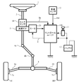
- the column shaft (steering shaft) 2 of the steering wheel 1 passes through the reduction gear 3, the universal joints 4a and 4b, the pinion rack mechanism 5, and the tie rods 6a and 6b. Further, they are connected to steering wheels 8L and 8R via hub units 7a and 7b.
- the column shaft 2 is provided with a torque sensor 10 for detecting the steering torque of the steering wheel 1, and a motor 20 for assisting the steering force of the steering wheel 1 is connected to the column shaft 2 via the reduction gear 3.
- Electric power is supplied from the battery 13 to the control unit (ECU) 100 that controls the electric power steering apparatus, and an ignition key signal is input through the ignition key 11.
- ECU control unit
- the control unit 100 calculates the steering assist command value of the assist (steering assist) command on the basis of the steering torque Th detected by the torque sensor 10 and the vehicle speed Vel detected by the vehicle speed sensor 12 to obtain a steering assist command value.
- the current supplied to the motor 20 is controlled by the current control value E subjected to the compensation or the like.
- the vehicle speed Vel can also be received from a CAN (Controller Area Network) or the like.
- the stability of the system, road surface information and disturbance are conventionally determined by a robust stabilization compensation unit in the control unit 100 as shown in, for example, JP-A-8-290778 (Patent Document 1).
- the sensitivity characteristics of the information are designed at the same time.
- Patent Document 2 Japanese Patent Application Laid-Open No. 2002-369565
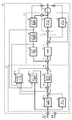
- a motor 20 for generating an auxiliary steering force of the steering apparatus is driven by a motor drive unit 21.
- the motor drive unit 21 is controlled by a control unit 100 shown by a two-dot chain line.
- the vehicle speed Vel from the vehicle speed detection system is input.
- a voltage Vm between motor terminals and a motor current value i are measured and output.
- the control unit 100 includes a torque system control unit 110 shown by a broken line which performs control using a steering torque Th, and a motor system control unit 120 shown by a dot-and-dash line which performs control related to driving of the motor 20.
- the torque system control unit 110 includes an assist amount calculation unit 111, a differentiation control unit 112, a yaw rate convergence control unit 113, a robust stabilization compensation unit 114, and a self aligning torque (SAT) estimation feedback unit 115.
- a subtraction unit 116C is provided.
- motor system control unit 120 includes compensation unit 121, disturbance estimation unit 122, motor angular velocity calculation unit 123, motor angular acceleration calculation unit 124, and motor characteristic compensation unit 125, and includes addition units 126A and 126B.
- the steering torque Th is input to the assist amount calculation unit 111, the differential control unit 112, the yaw rate convergence control unit 113, and the SAT estimation feedback unit 115, and all use the vehicle speed Vel as a parameter input.
- the assist amount calculation unit 111 calculates the assist torque amount based on the steering torque Th, and the yaw rate convergence control unit 113 receives the steering torque Th and the motor angular velocity ⁇ as input to improve the yaw convergence of the vehicle.
- the brakes are applied to the swinging motion.
- the differential control unit 112 improves the response of control near the neutral point of steering to realize smooth and smooth steering
- the SAT estimation feedback unit 115 calculates the steering torque Th and the assist amount calculation unit 111.
- a signal obtained by adding the output of the differential control unit 112 to the output of the differential control unit 112 by the addition unit 116A, the angular velocity ⁇ calculated by the motor angular velocity calculation unit 123, and the angular acceleration ⁇ from the motor angular acceleration calculation unit 124 are input
- the estimated and estimated SAT is subjected to signal processing using a feedback filter, and appropriate road surface information is given as a reaction force to the steering wheel.
- the signal obtained by adding the output of the yaw rate convergence control unit 113 by the addition unit 116B7 to the signal obtained by adding the output of the differentiation control unit 112 by the addition unit 116A to the output of the assist amount calculation unit 111 is robust stabilization as the assist amount AQ. It is input to the compensation unit 114.
- the robust stabilization compensation unit 114 is a compensation unit disclosed in, for example, Japanese Patent Laid-Open No. 8-290778, and removes a peak value at a resonant frequency of a resonant system including an inertial element and a spring element included in a detected torque to perform control. It compensates for the phase shift of the resonance frequency which impairs the responsiveness and stability of the system.
- the assist amount Ia capable of transmitting road surface information as a reaction force to the steering wheel is obtained.
- the motor angular velocity calculation unit 123 calculates the motor angular velocity ⁇ based on the voltage Vm between the motor terminals and the motor current value i.
- the motor angular velocity ⁇ corresponds to the motor angular acceleration calculation unit 124, the yaw rate convergence control unit 113 and SAT.
- the information is input to the estimation feedback unit 115.
- the motor angular acceleration calculation unit 124 calculates the motor angular acceleration ⁇ based on the input motor angular velocity ⁇ , and the calculated motor angular acceleration ⁇ is input to the motor characteristic compensation unit 125.
- the assist amount Ia obtained by subtracting the output of the SAT estimation feedback unit 115 from the output of the robust stabilization compensation unit 114 is added by the adding unit 126A to the output Ic of the motor characteristic compensation unit 125, and the added signal is differentiated as the current command value Ir.
- the signal is input to a compensation unit 121 including a compensation unit and the like.
- a signal obtained by adding the output of the disturbance estimation unit 122 by the addition unit 126 B to the current command value Ira compensated by the compensation unit 121 is input to the motor drive unit 21 and the disturbance estimation unit 122.
- the disturbance estimation unit 122 is a device as disclosed in JP-A-8-310417 and is a signal obtained by adding the output of the disturbance estimation unit 122 to the current command value Ira compensated by the compensation unit 121 which is a control target of the motor output. Based on the motor current value i, the desired motor control characteristic in the output reference of the control system can be maintained, and the stability of the control system is not lost.
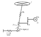
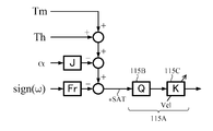
- SAT is estimated from motor angular velocity ⁇ , motor angular acceleration ⁇ , steering assist force Tm and steering torque Th by obtaining in advance inertia J and static friction Fr of motor 20 as constants. Can. From this reason, the steering torque Th, the motor angular velocity ⁇ , the motor angular acceleration ⁇ , and the output of the assist amount calculation unit 111 are input to the SAT estimation feedback unit 115, respectively.
- the SAT estimated current value * SAT estimated by the SAT estimation feedback unit 115 is fed back as it is, the steering becomes too heavy, so the steering feeling can not be improved. Therefore, as shown in FIG. 4, the SAT estimated current value * SAT is signal-processed using a feedback filter 115A having a vehicle speed sensitive gain and a frequency characteristic, and only information necessary for improving steering feeling is fed back. .
- the feedback filter used here is, as a static characteristic gain, a Q filter (phase delay) 115B having a gain that reduces the size of the estimated SAT to a necessary and sufficient value, and a gain section sensitive to the vehicle speed Vel as shown in FIG.
- the road surface information to be fed back is made smaller if the road surface information is relatively low in importance, such as stationary and low speed driving, with the 115C.
- the SAT estimation feedback is configured so as to be compatible with the frequency band in which the disturbance to be suppressed exists and the frequency band in which the disturbance to be transmitted is present. There is no function to counteract positively.
- the brake judder is a floor pedal vibration generated when the vehicle is braked, and may be accompanied by a vibration in the steering rotation direction.
- the braking torque fluctuation generated by DTV (Disk Thickness Variation) of the brake disc is a source of excitation, and has primary and higher order components of the rotation of the wheel. This is amplified by resonance and the like before and after the suspension, and transmitted to the vehicle body and the steering system, resulting in floor pedal vibration and steering vibration.
- shimmy refers to vibration generated in the direction of steering rotation when the vehicle is traveling, and imbalances and non-uniformities in the rotating parts such as tires and wheels serve as an excitation source, and are amplified by suspension resonance, and steering via a steering system. It becomes vibration in the direction of rotation.
- Such a brake judder or shimmy is not considered at all in the device of Patent Document 2, and in JP 2002-145075 (PT 3) and JP 2002-161969 (PT 4), the brake judder or shimmy is not used.
- the device for damping the vibration is disclosed, all of them are mechanical responses, and there is a problem that the cost is increased and fine control such as vehicle speed response can not be performed.
- the inertia or friction of the steering system is large, the vibration due to the brake judder is not transmitted to the steering wheel, but it is desirable that the inertia or friction of the steering system be as small as possible for good steering feeling and vehicle stability.
- a target secondary steering angle or a target steering angle to be added by the secondary steering angle superposition mechanism is generated based on the steering wheel angle detection value from the steering wheel angle detection means and the transfer characteristic. So that the target secondary steering angle coincides with the secondary steering angle detection value from the secondary steering angle detection means, or the target secondary steering angle coincides with the secondary steering angle detection value from the secondary steering angle detection means.
- a target drive amount calculation means for calculating a target drive amount of the motor and a motor drive means for driving the motor according to the target drive amount are provided, and the steering wheel is steered according to the steering wheel of the driver.
- the steering angle control of the steering wheel is performed in the automatic steering mode such as parking assistance and automatic traveling, but the friction (SAT) that the tire receives from the road surface changes due to the effects of vehicle speed, road surface conditions (slope, moisture, etc.)
- SAT friction
- the followability of the actual steering angle with respect to the target steering angle of the column axis angle changes, and the solution of the problem is also demanded.
- the present invention has been made under the circumstances as described above, and an object of the present invention is to facilitate tuning by performing signal processing of road surface information and the like in a high frequency region, thereby suppressing brake judder and shimmy. Safe and comfortable steering performance can be obtained, and in automatic steering mode (parking support function), steering can be performed accurately according to the calculated target steering angle, and smooth steering can be performed even if the target steering angle is sudden steering, and low vehicle speed It is another object of the present invention to provide an electric power steering apparatus capable of always following a target steering angle by raising the response or the steady state deviation.
- the present invention calculates the motor current command value 1 based on the steering torque and the vehicle speed, drives the motor based on the motor current command value 1 to assist control of the steering system, and performs automatic steering mode and manual steering mode
- the object of the present invention is to provide a motor current command based on a target steering angle, an actual steering angle, a motor angular velocity and motor angular acceleration of the motor, the steering torque, and a previous current command value.
- a steering angle control unit that calculates a value 2; and a switching unit that inputs and switches the motor current command value 1 and the motor current command value 2; and the steering angle control unit controls the target steering angle and the actual steering.
- a feedback control unit that generates a feedback control current command value based on an angle, the motor angular velocity, and the steering torque; Motor current command value 2 from the feedback control current command value and the SAT compensation current command value, and a SAT compensation unit that generates a SAT compensation current command value based on the angular acceleration, the steering torque, and the previous current command value.
- the switching unit is switched according to a switching command of the automatic steering mode and the manual steering mode, and drive control of the motor is performed based on the motor current command value 2 in the automatic steering mode. Is achieved by
- the object of the present invention is to provide a rate limiter for smoothing the target steering angle by the feedback control unit, an LPF connected to the output of the rate limiter, and an angular deviation between the output of the LPF and the actual steering angle.
- a first proportional gain unit for multiplying by a proportional gain
- an integral gain unit for integrating an error gain from the first proportional gain unit and a velocity deviation between the motor angular velocity and an integral gain, and multiplying the velocity deviation by a proportional gain
- Output of the differential gain unit according to a deviation value between the output of the integral gain unit and the output of the second proportional gain unit.
- the output unit that outputs the feedback control current command value by limiting the upper and lower limit values by adding A SAT estimation unit that calculates a SAT estimated current value based on a motor angular velocity, the motor angular acceleration, and a previous current command value, an LPF that receives the SAT estimated current value and has a cutoff frequency characteristic higher than the angle response frequency And the vehicle speed sensitive gain unit that outputs the SAT compensation current command value by multiplying the output of the LPF by the vehicle speed variable gain, or the SAT estimation unit determines the viscosity coefficient of friction to the motor angular velocity.
- a first subtraction unit that subtracts a value obtained by multiplying angular acceleration by inertia from the addition result of the addition unit, and a value obtained by encoding the motor angular velocity and multiplying friction are subtracted from the subtraction result of the first subtraction unit More effectively by comprising a second subtracting unit for outputting the SAT estimated current value, or by connecting a limiter for limiting the upper and
- the target steering angle calculated from data of a camera (image), distance sensor, etc.
- control gain is increased to increase responsiveness or steady state deviation, and the target steering angle can be approached even at low vehicle speeds.
- the SAT is estimated, this estimated SAT is filtered by an LPF set to a cutoff frequency higher than the angle response frequency, the filtered value is multiplied by the vehicle speed gain set according to the vehicle speed, and a compensation value is obtained. Since the addition is performed, the followability of the actual steering angle to the target steering angle can be further improved.
- the steering angle control of the steering wheel is performed in the automatic steering mode such as parking assistance and automatic traveling, but the friction (SAT) the tire receives from the road surface changes due to the influence of the vehicle speed and road surface conditions (tilt, moisture etc.)
- SAT friction
- the present invention estimates the SAT, filters this estimated SAT with an LPF set to a cutoff frequency higher than the angular response frequency, and sets the SAT value after filtering according to the vehicle speed.
- the followability of the actual steering angle to the target steering angle is improved by multiplying by the above and adding to the current command value as the compensation value.
- the feedback control current command value generated by the feedback control unit is added from the SAT compensation current command value generated by the SAT compensation unit to cancel the influence of the reaction force (SAT) received from the road surface by the tire. Generates a motor torque.
- SAT reaction force
- the influence of SAT disturbance generated during the steering angle control can be suppressed, and the followability of the steering angle control to the target steering angle can be improved.
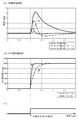
- the SAT changes according to the friction ⁇ between the tire and the road surface, which changes the response of the steering angle, which makes the vehicle difficult to handle.
- FIG. 6A shows an example of the steering angle response waveform
- FIG. 6B shows an example of the SAT estimated value waveform
- FIGS. 6A and 6B show response waveforms when a SAT disturbance step as shown in FIG. 6C is input after 1 second from time (second).
- an LPF low-pass filter
- the steering angle response waveform and the SAT estimated value waveform change.
- the road surface reaction force (SAT) transmitted to the steering system through the tire varies depending on the vehicle speed. Therefore, when automatically controlling the steering to the calculated target steering angle in the automatic steering mode, the response of the steering angle differs depending on the vehicle speed. Therefore, in the present invention, the motor current command value for automatic control is adjusted in accordance with the vehicle speed to reduce the influence of the road surface reaction force that the tire receives from the road surface. Further, in the present invention, the target steering angle is smoothed by the rate limiter, and the effect of reducing the steering wheel angle response is obtained even when the target steering angle is suddenly changed. Regardless of the vehicle speed, the vehicle can be accurately moved relative to the target steering angle, which is safer for the driver.
- FIG. 7 shows a configuration example of the present invention, in which a rotation sensor 151 such as a resolver for detecting a motor rotation angle ⁇ s is connected to the motor 150.
- the motor 150 is an ECU 130 and EPS (electric power Driving is controlled via the ECU 140 on the steering device side.
- the ECU 130 on the vehicle side outputs a switching command unit 131 that outputs a switching command SW for the automatic steering mode or the manual steering mode based on a button, a switch or the like indicating the driver's intention, and a signal such as a camera (image) or distance sensor
- a target steering angle generation unit 132 that generates a target steering angle ⁇ t based on
- the actual steering angle ⁇ r detected by the steering angle sensor 152 provided on the column axis and the vehicle speed Vel from the vehicle speed sensor 153 are input to the steering angle control unit 200 in the ECU 140 on the EPS side via the ECU 130.
- the steering angle sensor 152 may be a column axis (including intermediate and pinion shafts), rack displacement of a rack and pinion, and a steering angle estimated value by wheel speed.
- the vehicle speed Vel can also be received from CAN or the like.
- the switching command unit 131 is based on a signal identifying that the vehicle is in the automatic steering mode, for example, a signal of a vehicle state by a button or a switch provided around the dashboard or steering wheel or a parking mode provided at a shift.
- the switching command SW is output to the switching unit 142 in the ECU 140 on the EPS side.
- the target steering angle generation unit 132 generates a target steering angle ⁇ t by a known method based on data of a camera (image), a distance sensor, etc., and generates the target steering angle ⁇ t as a rudder in the ECU 140 on the EPS side. Input to the angle control unit 200.
- the ECU 140 on the EPS side outputs the target steering angle ⁇ t, the actual steering angle ⁇ r, the vehicle speed Vel, and the torque control unit 141 which outputs the motor current command value Itref calculated as described above based on the steering torque Th and the vehicle speed Vel.
- a steering angle control unit 200 that calculates and outputs a motor current command value Imref for automatic steering angle control based on the steering torque Th from the sensor 154, the motor angular velocity ⁇ , and the motor angular acceleration ⁇ , and the motor current by the switching command SW Current control / drive unit 143 which drives and controls motor 150 based on switching unit 142 switching command values Itref and Imref, and motor current command value (Itref or Imref) from switching unit 142, motor rotation from rotation sensor 151
- a motor angular velocity calculation unit 144 that calculates the motor angular velocity ⁇ based on the angle ⁇ s; It has and a motor angular acceleration calculation unit 145 for calculating the motor angular acceleration ⁇ based on the angular velocity omega.
- Switching unit 142 switches torque control mode (manual steering mode) by torque control unit 141 and automatic steering mode by steering angle control unit 200 based on switching command SW from switching command unit 131 of ECU 130, and performs torque control.
- the motor current command value Itref is output
- the motor current command value Imref is output.
- the current control / drive unit 143 is configured by a PI current control unit, a PWM control unit, an inverter, and the like.
- the configuration of the steering angle control unit 200 is as shown in FIG. 8, and the feedback control current command value Ifref is calculated by inputting the target steering angle ⁇ t, the actual steering angle ⁇ r, the motor angular velocity ⁇ and the steering torque Th.
- SAT compensation current command value Isref is calculated by inputting the feedback control unit 210 which outputs and outputs the motor angular velocity ⁇ , the steering torque Th, the motor angular acceleration ⁇ , and the previous current command value Iref (Z -1 ) Unit 230, an adding unit 201 which adds the SAT compensation current command value Isref to the feedback control current command value Ifref and outputs the motor current command value Imo, and adds the motor current command value Imo to the current command value to produce the motor current command It comprises the addition part 202 which outputs value Imref.
- the feedback control unit 210 has a function of suppressing torsional vibration generated by the torsion bar and the steering inertia. Further, the adding unit 201 and the adding unit 202 constitute an output unit.
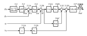
- the feedback control unit 210 is configured as shown in FIG. 9 and is a position control system in which the speed control loop system is a minor loop, and smoothing is performed when the target steering angle ⁇ t changes rapidly, that is, a predetermined time
- the target steering angle ⁇ t is input to the rate limiter 211 that smoothly changes within the range of change rate, and the target steering angle ⁇ ta that has passed through the LPF 212 that removes high frequency disturbance is additionally input to the subtracting unit 213A.
- the actual steering angle ⁇ r is subtracted and input to the subtracting unit 213A, the angular deviation from the smoothed target steering angle ⁇ ta is multiplied by the gain Kpp by the proportional gain (Kpp) unit 214, and added and input to the subtracting unit 213B as the error speed ⁇ e. Ru.
- the motor angular velocity ⁇ is subtracted from the motor angular velocity calculation unit 144 into the subtraction unit 213B, and the calculated speed deviation Df is passed through the integration unit 216A, multiplied by the gain Kvi by the integration gain (Kvi) unit 216B, and added to the subtraction unit 213C.
- the speed deviation Df is multiplied by the gain Kvp by the proportional gain (Kvp) unit 216C and subtracted and input to the subtraction unit 213C.
- the subtraction result in the subtraction unit 213C is input to the addition unit 213D.
- the steering torque Th from the torque sensor 154 passes through the differential unit 215A, is multiplied by the gain Kc by the differential gain (Kc) unit 215B, is input to the addition unit 213D, and the addition result by the addition unit 213D limits the upper and lower limit values by the limiter 217. And output as a feedback control current command value Ifref.
- An output unit is configured by the subtraction unit 213C, the addition unit 213D, and the limiter 217.
- the rate limiter 211 smooths and outputs the target steering angle ⁇ t when the target steering angle ⁇ t changes rapidly, and has a configuration as shown in FIG. 10, for example. That is, the target steering angle ⁇ t is additionally input to the subtraction unit 211-1, and the steering angle ⁇ t1 which is the subtraction result from the past value is set by the variation setting unit 211-2 as the variation setting unit 211-2.
- the change setting unit 211-2 sets the difference ⁇ t1 between the past value from the holding unit (Z -1 ) 211-4 and the input ( ⁇ t), and the change unit ⁇ t2 in the addition unit 211-3 and the past value The addition result is output as a new target steering angle ⁇ t3.
- the change amount setting unit 211-2 is for making the change amount not exceed the set upper limit and lower limit, and its characteristic is to obtain a difference with the input (target steering angle) ⁇ t every operation cycle T, and change If the difference is out of the range between the upper limit and the lower limit of the minute setting unit 211-2, the output ⁇ t3 is changed stepwise as shown in FIG. 11 by repeatedly adding the difference to the past value. The output ⁇ t3 is made to coincide with the target steering angle ⁇ t.
- the SAT compensation unit 230 obtains a SAT torque (converted to a column axis) from an equation of motion about the column axis, and obtains a SAT estimated current value I SAT that is a motor current corresponding to the SAT torque. Then, the SAT estimated current value I SAT is passed through an LPF set to a cutoff frequency higher than the angular response frequency, and is further multiplied by the vehicle speed sensitive gain set as the vehicle speed to obtain the SAT compensation current command value Isref.
- the SAT torque (in terms of column axis) is obtained from the equation of motion around the column axis, and the SAT estimated current value I SAT corresponding to the SAT torque is obtained as in the following formula 3.
- Ic is the column axis converted to the column axis, the pinion rack mechanism, the total moment of inertia of the tire, ⁇ c is the column axis angular velocity, Th is the steering torque (torsion torque of the torsion bar), and T Frc is the Coulomb friction acting on the column axis And c are column shaft viscous friction coefficients, and Kt is a coefficient (motor torque constant x speed reduction ratio) for converting current values into column shaft torques.
- the SAT compensation unit 230 based on Equation 3 is configured as shown in FIG.
- the motor angular velocity ⁇ is input to the viscous friction coefficient (c) unit 231, multiplied by the viscous friction coefficient c, and added to the adder / subtractor 232A. While being input, it is encoded by a sign unit 233, is multiplied by coulomb friction T Frc by a coulomb friction (T Frc ) unit 234, and is added to an addition / subtraction unit 232A.
- the coding part 233 and the coulomb friction part 234 constitute a coulomb friction part.
- the steering torque Th is subtracted and input to the adding and subtracting unit 232A, and the addition and subtraction result is added and input to the adding unit 232B.
- the motor angular acceleration ⁇ (here, the motor angular acceleration ⁇ is equal to the column axis angular acceleration) is input to the total moment of inertia (Ic) portion 235, multiplied by the total inertia moment Ic, and input to the adding portion 232B,
- the addition result is input to the coefficient (1 / Kt) unit 236, multiplied by 1 / Kt, and added and input to the subtraction unit 232C.
- the previous current command value Iref (Z -1 ) is subtracted and input to the subtracting unit 232C, and the difference is output as a SAT estimated current value I SAT that generates a motor torque corresponding to SAT.
- the addition unit 232B, the coefficient unit 236, and the subtraction unit 232C constitute an output coefficient unit.
- the cutoff frequency is filtered by the LPF 237 having a characteristic higher than the response frequency (for example, 1 Hz) of steering angle control.
- the filtering output of the LPF 237 is multiplied by the gain G by the gain (G) unit 238.
- the limiter 239 limits the upper and lower limit values of the current value command value multiplied by the gain G, and the limiter 239 outputs the SAT compensation current command value Isref.
- the limiter 239 is not a necessary element.
- the gain section 238 may be vehicle speed sensitive, and the gain G characteristic of the vehicle speed sensitive gain may be, for example, a characteristic in which the gain G becomes gradually smaller as the vehicle speed Vel increases as shown in FIG.
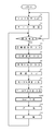
- step S1 When the operation of the steering system starts, the torque control by the torque control unit 141 is performed (step S1), and the motor 150 is driven by the current control / drive unit 143 using the motor current command value Itref (step S2). The above operation is repeated until the switching command SW is output from the switching command unit 131 (step S3).
- the target steering angle ⁇ t is input from the target steering angle generating unit 132 (step S4), and the actual steering angle ⁇ r is input from the steering angle sensor 152 (Step S5)
- steering torque Th is input from torque sensor 154 (step S6)
- vehicle speed Vel is input from vehicle speed sensor 153 (step S7)
- motor angular velocity ⁇ is input from motor angular velocity calculation unit 144 (step S8)
- the motor angular acceleration ⁇ is input from the motor angular acceleration calculation unit 145 (step S9), and the motor current command value Imref is generated by the steering angle control unit 200 (step S100).
- the order of inputting the target steering angle ⁇ t, the actual steering angle ⁇ r, the steering torque Th, the motor angular velocity ⁇ , and the motor angular acceleration ⁇ is arbitrary.
- switching unit 142 is switched by switching command SW from switching command unit 131 (step S10), and motor 150 is driven by current control / drive unit 143 using motor current command value Imref from steering angle control unit 200. (Step S11) The process returns to step S3. The drive control based on the motor current command value Imref is repeated until the switching command SW is changed from the switching command unit 131.
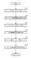
- the generation of the motor current command value Imref is performed by the steering angle control unit 200, and the operation of generating the motor current command value Imref by the steering angle control unit 200 is as shown in the flowchart of FIG.
- the feedback control unit 210 receives the target steering angle ⁇ t, the actual steering angle ⁇ r, the motor angular velocity ⁇ and the steering torque Th (step S101), and generates a feedback control current command value Ifref (step S102).
- the SAT compensation unit 230 receives the motor angular velocity ⁇ , the steering torque Th, the motor angular acceleration ⁇ , and the previous current command value Iref (Z -1 ) (step S103), and generates the SAT compensation current command value Isref. (Step S104).
- the target steering angle ⁇ t is input to the rate limiter 211 (step S110), the rate limiting operation as described above is performed by the rate limiter 211 (step S111), and the target steering angle ⁇ ta passed through the LPF 212 is input to the subtraction unit 213A.
- the actual steering angle ⁇ r is input from the steering angle sensor 152 (step S112), and subtraction of “ ⁇ ta ⁇ r” is performed by the subtraction unit 213A (step S113).
- the gain is multiplied by Kpp and added to the subtraction unit 213B (step S114).
- the motor angular velocity ⁇ is subtracted and input to the subtracting unit 213B, and a velocity deviation from the angular velocity multiplied by the gain Kpp is obtained (step S115).
- the velocity deviation obtained by the subtracting unit 213B is integrated and multiplied by the gain Kvi by the integrating unit 216A and the integral gain unit 216B and added to the subtracting unit 213C (step S116), and the proportional gain Kvp is multiplied by the proportional gain unit 216C.
- the signal is subtracted and input to the subtracting unit 213C (step S117), and subtracted by the subtracting unit 213C (step S118).
- the steering torque Th is input (step S120), and the steering torque Th is differentiated by the differentiation unit 215A, multiplied by the differential gain Kc by the differentiation gain unit 215B, and input to the addition unit 213C (step S121).
- the addition unit 213D adds the subtraction value from the subtraction unit 213C (step S122), limits the upper and lower limit values by the limiter 217 (step S123), and outputs the result as the feedback control current command value Ifref (step S124).
- the motor angular velocity ⁇ and the steering torque Th are input (step S130), and the viscous friction coefficient unit 231 multiplies the motor angular velocity ⁇ by the viscous friction coefficient c (step S131), and encoding is performed by the code unit 233.
- the friction T Frc is multiplied (step S132), the output of the viscous friction coefficient unit 231 and the output of the coulomb friction unit 234 are added, and the steering torque Th is added / subtracted by the adding / subtracting unit 232A (step S133).
- the total moment of inertia unit 235 inputs the motor angular acceleration ⁇ and multiplies the total moment of inertia Ic (step S132), and the adding unit 232B adds the results (step S135).
- the addition result in the adding unit 232B is multiplied by 1 / Kt in the coefficient unit 236 and added to the subtracting unit 232C, and the previous current command value Iref (Z -1 ) separately input (stored) is subtracted by the subtracting unit 232C (Step S137).
- the subtraction unit 232C outputs a SAT estimated current value I SAT that generates a motor torque corresponding to SAT , filters the SAT estimated current value I SAT with the LPF 237 (step S140), receives the vehicle speed Vel, and gains (G)
- the gain G is multiplied by the unit 238 (step S141), the upper and lower limit values are further limited by the limiter 239 (step S122), and the SAT compensation current command value Isref is output from the limiter 239 (step S143).
- the SAT compensation unit 230 in FIG. 12 is configured based on Equation 3, but can be configured similarly for the SAT estimation described in FIG. 4.
- the SAT compensation current command value Isref can be obtained.
Landscapes
- Engineering & Computer Science (AREA)
- Chemical & Material Sciences (AREA)
- Combustion & Propulsion (AREA)
- Transportation (AREA)
- Mechanical Engineering (AREA)
- Physics & Mathematics (AREA)
- Mathematical Physics (AREA)
- Steering Control In Accordance With Driving Conditions (AREA)
Abstract
Cette invention concerne un dispositif de direction assistée électrique facile à syntoniser et offrant une performance de direction sûre et confortable par suppression des vibrations et trépidations de frein, ledit dispositif assurant une direction précise conformément à un angle de direction cible calculé en mode de direction automatique, assurant une direction sans à-coups même quand l'angle de direction cible implique un virage serré et apte à poursuivre l'angle de direction cible même à une basse vitesse du véhicule par accroissement de la déviation de réaction ou de régime permanent. Ledit dispositif de direction assistée électrique comprend : une unité de commande d'angle de direction qui calcule une valeur de commande de courant de moteur ; et une unité de commutation qui commute les valeurs de commande de courant de moteur qui sont entrées. Ladite unité de commande d'angle de direction comprend en outre une unité de commande de réaction qui génère une valeur de commande de courant de commande de réaction, une unité de compensation de couple d'auto-alignement (SAT) qui génère une valeur de commande de courant de compensation de SAT et une unité de sortie qui génère une valeur de commande de courant moteur à partir de la valeur de commande de courant de commande de réaction et de la valeur de commande de courant de compensation SAT. Ladite unité de commutation est commutée en fonction d'une commande de commutation de mode de direction automatique/mode de direction manuel qui assure la commande de direction d'un véhicule sur la base d'une valeur de commande de courant de moteur en mode de direction automatique.
Priority Applications (4)
| Application Number | Priority Date | Filing Date | Title |
|---|---|---|---|
| CN201480029047.9A CN105246764B (zh) | 2014-01-29 | 2014-01-29 | 电动助力转向装置 |
| EP14880581.5A EP2977296B1 (fr) | 2014-01-29 | 2014-01-29 | Dispositif de direction assistée électrique |
| US14/419,796 US9327761B2 (en) | 2014-01-29 | 2014-01-29 | Electric power steering apparatus |
| PCT/JP2014/051931 WO2015114751A1 (fr) | 2014-01-29 | 2014-01-29 | Dispositif de direction assistée électrique |
Applications Claiming Priority (1)
| Application Number | Priority Date | Filing Date | Title |
|---|---|---|---|
| PCT/JP2014/051931 WO2015114751A1 (fr) | 2014-01-29 | 2014-01-29 | Dispositif de direction assistée électrique |
Publications (1)
| Publication Number | Publication Date |
|---|---|
| WO2015114751A1 true WO2015114751A1 (fr) | 2015-08-06 |
Family
ID=53756370
Family Applications (1)
| Application Number | Title | Priority Date | Filing Date |
|---|---|---|---|
| PCT/JP2014/051931 Ceased WO2015114751A1 (fr) | 2014-01-29 | 2014-01-29 | Dispositif de direction assistée électrique |
Country Status (4)
| Country | Link |
|---|---|
| US (1) | US9327761B2 (fr) |
| EP (1) | EP2977296B1 (fr) |
| CN (1) | CN105246764B (fr) |
| WO (1) | WO2015114751A1 (fr) |
Cited By (3)
| Publication number | Priority date | Publication date | Assignee | Title |
|---|---|---|---|---|
| CN105292246A (zh) * | 2015-12-07 | 2016-02-03 | 长春工业大学 | 汽车电动助力转向摩擦补偿控制方法 |
| CN111874089A (zh) * | 2020-07-14 | 2020-11-03 | 一汽奔腾轿车有限公司 | 一种基于c-eps采用角度接口的横向控制方法 |
| CN114919655A (zh) * | 2022-06-16 | 2022-08-19 | 上汽通用五菱汽车股份有限公司 | 车辆控制方法、系统、车辆及计算机可读存储介质 |
Families Citing this family (56)
| Publication number | Priority date | Publication date | Assignee | Title |
|---|---|---|---|---|
| CN104684792B (zh) * | 2013-02-07 | 2017-03-15 | 日本精工株式会社 | 电动助力转向装置 |
| JP6107928B2 (ja) * | 2013-03-08 | 2017-04-05 | 日本精工株式会社 | 電動パワーステアリング装置 |
| US9676409B2 (en) | 2013-03-11 | 2017-06-13 | Steering Solutions Ip Holding Corporation | Road wheel disturbance rejection based on hand wheel acceleration |
| US10155531B2 (en) | 2013-04-30 | 2018-12-18 | Steering Solutions Ip Holding Corporation | Providing assist torque without hand wheel torque sensor |
| CN105517877B (zh) * | 2013-08-22 | 2017-09-19 | 日本精工株式会社 | 电动助力转向装置的控制装置 |
| US10144445B2 (en) * | 2014-09-15 | 2018-12-04 | Steering Solutions Ip Holding Corporation | Modified static tire model for providing assist without a torque sensor for zero to low vehicle speeds |
| JP6287767B2 (ja) * | 2014-11-10 | 2018-03-07 | 株式会社デンソー | モータ制御装置 |
| WO2016088704A1 (fr) * | 2014-12-02 | 2016-06-09 | 日本精工株式会社 | Dispositif de direction assistée électrique |
| JP5990606B2 (ja) * | 2015-02-10 | 2016-09-14 | 本田技研工業株式会社 | 操舵装置及び操舵支援方法 |
| CN107750255B (zh) * | 2015-04-17 | 2022-08-30 | 安进研发(慕尼黑)股份有限公司 | 用于cdh3和cd3的双特异性抗体构建体 |
| US10336363B2 (en) | 2015-09-03 | 2019-07-02 | Steering Solutions Ip Holding Corporation | Disabling controlled velocity return based on torque gradient and desired velocity error |
| US10464594B2 (en) | 2015-09-03 | 2019-11-05 | Steering Solutions Ip Holding Corporation | Model based driver torque estimation |
| KR102307258B1 (ko) * | 2015-11-20 | 2021-10-01 | 현대모비스 주식회사 | 전동식 동력 조향장치의 조향복원 제어장치 및 그 방법 |
| KR102350043B1 (ko) * | 2015-11-20 | 2022-01-12 | 주식회사 만도 | 자동 조향 제어 시스템 및 방법 |
| WO2017150445A1 (fr) * | 2016-02-29 | 2017-09-08 | 日本精工株式会社 | Appareil de direction à assistance électrique |
| EP3375695B1 (fr) * | 2016-03-18 | 2019-12-11 | NSK Ltd. | Dispositif de commande pour dispositif de direction assistée électrique |
| DE102016209833B4 (de) * | 2016-06-03 | 2019-10-31 | Volkswagen Aktiengesellschaft | Verfahren und Vorrichtung zum Bestimmen eines Fahrerhandmoments an einem Lenkrad eines Fahrzeugs |
| EP3453592B1 (fr) * | 2016-06-06 | 2020-02-26 | NSK Ltd. | Dispositif de direction assistée électrique |
| US10155534B2 (en) | 2016-06-14 | 2018-12-18 | Steering Solutions Ip Holding Corporation | Driver intent estimation without using torque sensor signal |
| WO2018016436A1 (fr) * | 2016-07-20 | 2018-01-25 | 日本精工株式会社 | Dispositif de direction assistée électrique |
| WO2018021325A1 (fr) * | 2016-07-28 | 2018-02-01 | 日本精工株式会社 | Dispositif de direction assistée électrique |
| JP6481799B2 (ja) * | 2016-08-26 | 2019-03-13 | 日本精工株式会社 | 電動パワーステアリング装置の制御装置 |
| US10322748B2 (en) * | 2016-09-23 | 2019-06-18 | Jtekt Corporation | Motor controller and steering device |
| US10589780B2 (en) * | 2016-11-07 | 2020-03-17 | Nsk Ltd. | Electric power steering apparatus |
| EP3486141B1 (fr) * | 2016-11-11 | 2020-06-03 | NSK Ltd. | Dispositif de direction assistée électrique |
| JP6528786B2 (ja) * | 2017-01-13 | 2019-06-12 | トヨタ自動車株式会社 | 車両の運転支援装置 |
| JP6590090B2 (ja) * | 2017-02-20 | 2019-10-16 | 日本精工株式会社 | 電動パワーステアリング装置 |
| EP3539848B1 (fr) * | 2017-03-16 | 2020-09-23 | NSK Ltd. | Dispositif de direction assistée électrique |
| CN106915383B (zh) * | 2017-03-23 | 2019-05-03 | 广州汽车集团股份有限公司 | 一种电动助力转向系统的控制方法及系统 |
| CN110891849B (zh) * | 2017-08-02 | 2021-11-26 | 日本精工株式会社 | 电动助力转向装置 |
| JP2019064399A (ja) * | 2017-09-29 | 2019-04-25 | 株式会社Subaru | ステアリング装置 |
| EP3640118A4 (fr) * | 2017-10-13 | 2020-11-11 | NSK Ltd. | Dispositif de direction assistée électrique |
| CN107885931B (zh) * | 2017-11-07 | 2020-12-25 | 长春工业大学 | 一种转向盘突变力矩人性化调节的汽车紧急避撞控制方法 |
| JP6637952B2 (ja) * | 2017-12-28 | 2020-01-29 | 株式会社Subaru | 車両の車線逸脱防止制御装置 |
| DE102019200971B4 (de) * | 2018-02-05 | 2025-07-10 | Denso Corporation | Lenksteuerungsvorrichtung |
| US10338539B1 (en) * | 2018-02-19 | 2019-07-02 | Hamilton Sundstrand Corporation | Actuator control system with transient reduction after redundancy level changes |
| US11110956B2 (en) * | 2018-02-22 | 2021-09-07 | Steering Solutions Ip Holding Corporation | Quadrant based friction compensation for tire load estimation in steering systems |
| JP6638012B2 (ja) * | 2018-03-16 | 2020-01-29 | 株式会社Subaru | 車両の車線逸脱防止制御装置 |
| US10689033B2 (en) * | 2018-03-27 | 2020-06-23 | Subaru Corporation | Vehicle driving assist apparatus |
| CN110576898B (zh) * | 2018-06-07 | 2022-03-11 | 华创车电技术中心股份有限公司 | 机动车辆转向控制系统及转向控制方法 |
| JP7247508B2 (ja) * | 2018-09-28 | 2023-03-29 | 日本電産株式会社 | ステアリング制御装置およびパワーステアリング装置 |
| US11511795B2 (en) * | 2018-10-11 | 2022-11-29 | Steering Solutions Ip Holding Corporation | Dither noise management in electric power steering systems |
| CN110001759B (zh) * | 2019-03-11 | 2021-04-20 | 江苏大学 | 基于eps状态机的辅助驾驶系统及状态切换方法 |
| JP7387998B2 (ja) * | 2019-04-15 | 2023-11-29 | 株式会社ジェイテクト | 操舵制御装置 |
| JP7170971B2 (ja) * | 2019-04-18 | 2022-11-15 | 日本精工株式会社 | 車両用操向システムの制御装置 |
| CN113119973B (zh) * | 2019-12-31 | 2022-10-25 | 上海汽车集团股份有限公司 | 助力力矩的切换控制方法、装置及计算机存储介质 |
| JP7347346B2 (ja) * | 2020-06-23 | 2023-09-20 | いすゞ自動車株式会社 | 操舵制御システム、電動パワーステアリング装置および操舵制御プログラム |
| CN115071807B (zh) * | 2021-03-15 | 2023-09-12 | 北汽福田汽车股份有限公司 | 一种控制方法、装置及车辆 |
| DE102021202482B4 (de) * | 2021-03-15 | 2023-06-29 | Continental Automotive Technologies GmbH | Regelungseinrichtung und Verfahren zur Lenkwinkelregelung eines Fahrzeugs |
| US12139213B2 (en) * | 2021-06-03 | 2024-11-12 | Nsk Ltd. | Control apparatus of steering system for vehicles |
| CN113428219A (zh) * | 2021-07-31 | 2021-09-24 | 重庆长安汽车股份有限公司 | 一种基于传递函数快速响应控制汽车安全的系统和方法 |
| KR20230023081A (ko) * | 2021-08-09 | 2023-02-17 | 현대모비스 주식회사 | 전동식 조향시스템의 제어 장치 및 방법 |
| JP7597051B2 (ja) * | 2022-02-10 | 2024-12-10 | トヨタ自動車株式会社 | ステアリングシステム |
| KR20240169448A (ko) * | 2023-05-24 | 2024-12-03 | 에이치엘만도 주식회사 | 조향 시스템의 모터 제어 장치 및 이에 의한 모터 제어 방법 |
| BE1031887B1 (de) * | 2023-08-11 | 2025-03-10 | Thyssenkrupp Presta Ag | Lenkeinrichtung für ein Kraftfahrzeug |
| CN118220323B (zh) * | 2024-04-08 | 2024-10-18 | 昌辉汽车转向系统(黄山)有限公司 | 用于线控转向系统的路面振动反馈控制系统 |
Citations (9)
| Publication number | Priority date | Publication date | Assignee | Title |
|---|---|---|---|---|
| JPH08290778A (ja) | 1995-04-21 | 1996-11-05 | Nippon Seiko Kk | 電動パワ−ステアリング装置の制御装置 |
| JPH08310417A (ja) | 1995-05-15 | 1996-11-26 | Nippon Seiko Kk | 電動パワ−ステアリング装置の制御装置 |
| JP2002145075A (ja) | 2000-11-06 | 2002-05-22 | Honda Motor Co Ltd | ステアリングホイールの制振装置 |
| JP2002161969A (ja) | 2000-11-24 | 2002-06-07 | Honda Motor Co Ltd | ステアリングラックの制振構造 |
| JP2002369565A (ja) | 2001-06-07 | 2002-12-20 | Nsk Ltd | 電動パワーステアリング装置の制御装置 |
| JP2007269140A (ja) * | 2006-03-31 | 2007-10-18 | Nsk Ltd | 電動パワーステアリング装置の制御装置 |
| WO2008146372A1 (fr) | 2007-05-30 | 2008-12-04 | Mitsubishi Electric Corporation | Boîtier de direction de véhicule |
| JP2013193490A (ja) * | 2012-03-16 | 2013-09-30 | Nsk Ltd | 電動パワーステアリング装置 |
| JP2013252729A (ja) * | 2012-06-05 | 2013-12-19 | Nsk Ltd | 電動パワーステアリング装置 |
Family Cites Families (17)
| Publication number | Priority date | Publication date | Assignee | Title |
|---|---|---|---|---|
| JP3622329B2 (ja) * | 1996-03-08 | 2005-02-23 | スズキ株式会社 | 車両操舵装置 |
| JP3668340B2 (ja) * | 1996-09-05 | 2005-07-06 | 本田技研工業株式会社 | 車両操舵装置 |
| KR20020043069A (ko) * | 2000-12-01 | 2002-06-08 | 밍 루 | 전동식 파워 스티어링 시스템에 있어서 모터 제어 장치 |
| JP3637849B2 (ja) * | 2000-07-06 | 2005-04-13 | 日産自動車株式会社 | 車線追従走行制御装置 |
| JP3856690B2 (ja) * | 2001-11-30 | 2006-12-13 | 株式会社ジェイテクト | 電動パワーステアリング装置 |
| JP3674919B2 (ja) * | 2002-03-19 | 2005-07-27 | 本田技研工業株式会社 | 電動パワーステアリング装置とその制御方法 |
| JP2006117181A (ja) * | 2004-10-25 | 2006-05-11 | Favess Co Ltd | 操舵制御装置 |
| JP4600653B2 (ja) * | 2004-10-28 | 2010-12-15 | 株式会社ジェイテクト | 操舵制御装置 |
| JP4916820B2 (ja) * | 2006-08-29 | 2012-04-18 | 富士重工業株式会社 | 車両の操舵制御装置 |
| JP5387878B2 (ja) * | 2008-03-31 | 2014-01-15 | 株式会社ジェイテクト | モータ制御装置 |
| JP5526630B2 (ja) * | 2009-07-08 | 2014-06-18 | 株式会社ジェイテクト | 電動パワーステアリング装置 |
| JP5430505B2 (ja) * | 2010-06-25 | 2014-03-05 | トヨタ自動車株式会社 | 車両の制御装置 |
| JP5983759B2 (ja) * | 2012-11-08 | 2016-09-06 | トヨタ自動車株式会社 | 車両の走行制御装置 |
| US9393960B2 (en) * | 2012-11-28 | 2016-07-19 | Toyota Jidosha Kabushiki Kaisha | Vehicle cruise control device |
| JP6107928B2 (ja) * | 2013-03-08 | 2017-04-05 | 日本精工株式会社 | 電動パワーステアリング装置 |
| EP2933169B1 (fr) * | 2013-04-04 | 2018-01-10 | NSK Ltd. | Appareil de direction assistee electrique |
| JP5939238B2 (ja) * | 2013-11-29 | 2016-06-22 | トヨタ自動車株式会社 | 車両用操舵制御装置 |
-
2014
- 2014-01-29 US US14/419,796 patent/US9327761B2/en not_active Expired - Fee Related
- 2014-01-29 WO PCT/JP2014/051931 patent/WO2015114751A1/fr not_active Ceased
- 2014-01-29 CN CN201480029047.9A patent/CN105246764B/zh not_active Expired - Fee Related
- 2014-01-29 EP EP14880581.5A patent/EP2977296B1/fr not_active Not-in-force
Patent Citations (9)
| Publication number | Priority date | Publication date | Assignee | Title |
|---|---|---|---|---|
| JPH08290778A (ja) | 1995-04-21 | 1996-11-05 | Nippon Seiko Kk | 電動パワ−ステアリング装置の制御装置 |
| JPH08310417A (ja) | 1995-05-15 | 1996-11-26 | Nippon Seiko Kk | 電動パワ−ステアリング装置の制御装置 |
| JP2002145075A (ja) | 2000-11-06 | 2002-05-22 | Honda Motor Co Ltd | ステアリングホイールの制振装置 |
| JP2002161969A (ja) | 2000-11-24 | 2002-06-07 | Honda Motor Co Ltd | ステアリングラックの制振構造 |
| JP2002369565A (ja) | 2001-06-07 | 2002-12-20 | Nsk Ltd | 電動パワーステアリング装置の制御装置 |
| JP2007269140A (ja) * | 2006-03-31 | 2007-10-18 | Nsk Ltd | 電動パワーステアリング装置の制御装置 |
| WO2008146372A1 (fr) | 2007-05-30 | 2008-12-04 | Mitsubishi Electric Corporation | Boîtier de direction de véhicule |
| JP2013193490A (ja) * | 2012-03-16 | 2013-09-30 | Nsk Ltd | 電動パワーステアリング装置 |
| JP2013252729A (ja) * | 2012-06-05 | 2013-12-19 | Nsk Ltd | 電動パワーステアリング装置 |
Cited By (3)
| Publication number | Priority date | Publication date | Assignee | Title |
|---|---|---|---|---|
| CN105292246A (zh) * | 2015-12-07 | 2016-02-03 | 长春工业大学 | 汽车电动助力转向摩擦补偿控制方法 |
| CN111874089A (zh) * | 2020-07-14 | 2020-11-03 | 一汽奔腾轿车有限公司 | 一种基于c-eps采用角度接口的横向控制方法 |
| CN114919655A (zh) * | 2022-06-16 | 2022-08-19 | 上汽通用五菱汽车股份有限公司 | 车辆控制方法、系统、车辆及计算机可读存储介质 |
Also Published As
| Publication number | Publication date |
|---|---|
| CN105246764B (zh) | 2017-06-23 |
| CN105246764A (zh) | 2016-01-13 |
| EP2977296A1 (fr) | 2016-01-27 |
| US9327761B2 (en) | 2016-05-03 |
| US20160001810A1 (en) | 2016-01-07 |
| EP2977296A4 (fr) | 2017-03-22 |
| EP2977296B1 (fr) | 2018-07-18 |
Similar Documents
| Publication | Publication Date | Title |
|---|---|---|
| WO2015114751A1 (fr) | Dispositif de direction assistée électrique | |
| JP5915811B2 (ja) | 電動パワーステアリング装置 | |
| US9446789B2 (en) | Electric power steering apparatus | |
| JP7236037B2 (ja) | 車両用操舵装置 | |
| JP2014054885A (ja) | 電動パワーステアリング装置 | |
| EP2256019B1 (fr) | Appareil de commande de direction assistée électrique | |
| WO2014162769A1 (fr) | Dispositif de direction assistée électrique | |
| US20190002019A1 (en) | Electric power steering apparatus | |
| JP6069896B2 (ja) | 電動パワーステアリング装置 | |
| JP2013193490A (ja) | 電動パワーステアリング装置 | |
| WO2011037019A1 (fr) | Dispositif de conduite à énergie électrique | |
| WO2016027663A1 (fr) | Dispositif de direction à assistance électrique | |
| JPWO2019167661A1 (ja) | 車両用操向装置 | |
| JP2006199219A (ja) | 電動パワーステアリング装置の制御装置 | |
| JP4984602B2 (ja) | 電動パワーステアリング装置の制御装置 | |
| JP2010030391A (ja) | 車両の操舵装置 | |
| JP5428415B2 (ja) | 車両の操舵装置 | |
| JP2010143303A (ja) | 車両用操舵装置 | |
| JP6252062B2 (ja) | ステアリング制御装置 | |
| JP4347871B2 (ja) | 車両用操舵制御装置 | |
| JP4506475B2 (ja) | 車両用操舵制御装置 | |
| JP4517555B2 (ja) | 自動車の電動パワーステアリング装置 |
Legal Events
| Date | Code | Title | Description |
|---|---|---|---|
| WWE | Wipo information: entry into national phase |
Ref document number: 14419796 Country of ref document: US |
|
| 121 | Ep: the epo has been informed by wipo that ep was designated in this application |
Ref document number: 14880581 Country of ref document: EP Kind code of ref document: A1 |
|
| WWE | Wipo information: entry into national phase |
Ref document number: 2014880581 Country of ref document: EP |
|
| NENP | Non-entry into the national phase |
Ref country code: DE |
|
| NENP | Non-entry into the national phase |
Ref country code: JP |