WO2015111175A1 - ヒートポンプ装置 - Google Patents
ヒートポンプ装置 Download PDFInfo
- Publication number
- WO2015111175A1 WO2015111175A1 PCT/JP2014/051429 JP2014051429W WO2015111175A1 WO 2015111175 A1 WO2015111175 A1 WO 2015111175A1 JP 2014051429 W JP2014051429 W JP 2014051429W WO 2015111175 A1 WO2015111175 A1 WO 2015111175A1
- Authority
- WO
- WIPO (PCT)
- Prior art keywords
- heat exchanger
- heat
- refrigerant
- refrigeration cycle
- cascade
- Prior art date
Links
Images


Classifications
-
- F—MECHANICAL ENGINEERING; LIGHTING; HEATING; WEAPONS; BLASTING
- F25—REFRIGERATION OR COOLING; COMBINED HEATING AND REFRIGERATION SYSTEMS; HEAT PUMP SYSTEMS; MANUFACTURE OR STORAGE OF ICE; LIQUEFACTION SOLIDIFICATION OF GASES
- F25B—REFRIGERATION MACHINES, PLANTS OR SYSTEMS; COMBINED HEATING AND REFRIGERATION SYSTEMS; HEAT PUMP SYSTEMS
- F25B25/00—Machines, plants or systems, using a combination of modes of operation covered by two or more of the groups F25B1/00 - F25B23/00
- F25B25/005—Machines, plants or systems, using a combination of modes of operation covered by two or more of the groups F25B1/00 - F25B23/00 using primary and secondary systems
-
- F—MECHANICAL ENGINEERING; LIGHTING; HEATING; WEAPONS; BLASTING
- F25—REFRIGERATION OR COOLING; COMBINED HEATING AND REFRIGERATION SYSTEMS; HEAT PUMP SYSTEMS; MANUFACTURE OR STORAGE OF ICE; LIQUEFACTION SOLIDIFICATION OF GASES
- F25B—REFRIGERATION MACHINES, PLANTS OR SYSTEMS; COMBINED HEATING AND REFRIGERATION SYSTEMS; HEAT PUMP SYSTEMS
- F25B13/00—Compression machines, plants or systems, with reversible cycle
-
- F—MECHANICAL ENGINEERING; LIGHTING; HEATING; WEAPONS; BLASTING
- F25—REFRIGERATION OR COOLING; COMBINED HEATING AND REFRIGERATION SYSTEMS; HEAT PUMP SYSTEMS; MANUFACTURE OR STORAGE OF ICE; LIQUEFACTION SOLIDIFICATION OF GASES
- F25B—REFRIGERATION MACHINES, PLANTS OR SYSTEMS; COMBINED HEATING AND REFRIGERATION SYSTEMS; HEAT PUMP SYSTEMS
- F25B40/00—Subcoolers, desuperheaters or superheaters
-
- F—MECHANICAL ENGINEERING; LIGHTING; HEATING; WEAPONS; BLASTING
- F25—REFRIGERATION OR COOLING; COMBINED HEATING AND REFRIGERATION SYSTEMS; HEAT PUMP SYSTEMS; MANUFACTURE OR STORAGE OF ICE; LIQUEFACTION SOLIDIFICATION OF GASES
- F25B—REFRIGERATION MACHINES, PLANTS OR SYSTEMS; COMBINED HEATING AND REFRIGERATION SYSTEMS; HEAT PUMP SYSTEMS
- F25B7/00—Compression machines, plants or systems, with cascade operation, i.e. with two or more circuits, the heat from the condenser of one circuit being absorbed by the evaporator of the next circuit
-
- F—MECHANICAL ENGINEERING; LIGHTING; HEATING; WEAPONS; BLASTING
- F25—REFRIGERATION OR COOLING; COMBINED HEATING AND REFRIGERATION SYSTEMS; HEAT PUMP SYSTEMS; MANUFACTURE OR STORAGE OF ICE; LIQUEFACTION SOLIDIFICATION OF GASES
- F25B—REFRIGERATION MACHINES, PLANTS OR SYSTEMS; COMBINED HEATING AND REFRIGERATION SYSTEMS; HEAT PUMP SYSTEMS
- F25B2313/00—Compression machines, plants or systems with reversible cycle not otherwise provided for
- F25B2313/003—Indoor unit with water as a heat sink or heat source
-
- F—MECHANICAL ENGINEERING; LIGHTING; HEATING; WEAPONS; BLASTING
- F25—REFRIGERATION OR COOLING; COMBINED HEATING AND REFRIGERATION SYSTEMS; HEAT PUMP SYSTEMS; MANUFACTURE OR STORAGE OF ICE; LIQUEFACTION SOLIDIFICATION OF GASES
- F25B—REFRIGERATION MACHINES, PLANTS OR SYSTEMS; COMBINED HEATING AND REFRIGERATION SYSTEMS; HEAT PUMP SYSTEMS
- F25B2313/00—Compression machines, plants or systems with reversible cycle not otherwise provided for
- F25B2313/023—Compression machines, plants or systems with reversible cycle not otherwise provided for using multiple indoor units
- F25B2313/0233—Compression machines, plants or systems with reversible cycle not otherwise provided for using multiple indoor units in parallel arrangements
-
- F—MECHANICAL ENGINEERING; LIGHTING; HEATING; WEAPONS; BLASTING
- F25—REFRIGERATION OR COOLING; COMBINED HEATING AND REFRIGERATION SYSTEMS; HEAT PUMP SYSTEMS; MANUFACTURE OR STORAGE OF ICE; LIQUEFACTION SOLIDIFICATION OF GASES
- F25B—REFRIGERATION MACHINES, PLANTS OR SYSTEMS; COMBINED HEATING AND REFRIGERATION SYSTEMS; HEAT PUMP SYSTEMS
- F25B2313/00—Compression machines, plants or systems with reversible cycle not otherwise provided for
- F25B2313/027—Compression machines, plants or systems with reversible cycle not otherwise provided for characterised by the reversing means
- F25B2313/0272—Compression machines, plants or systems with reversible cycle not otherwise provided for characterised by the reversing means using bridge circuits of one-way valves
-
- F—MECHANICAL ENGINEERING; LIGHTING; HEATING; WEAPONS; BLASTING
- F25—REFRIGERATION OR COOLING; COMBINED HEATING AND REFRIGERATION SYSTEMS; HEAT PUMP SYSTEMS; MANUFACTURE OR STORAGE OF ICE; LIQUEFACTION SOLIDIFICATION OF GASES
- F25B—REFRIGERATION MACHINES, PLANTS OR SYSTEMS; COMBINED HEATING AND REFRIGERATION SYSTEMS; HEAT PUMP SYSTEMS
- F25B2313/00—Compression machines, plants or systems with reversible cycle not otherwise provided for
- F25B2313/027—Compression machines, plants or systems with reversible cycle not otherwise provided for characterised by the reversing means
- F25B2313/02741—Compression machines, plants or systems with reversible cycle not otherwise provided for characterised by the reversing means using one four-way valve
-
- F—MECHANICAL ENGINEERING; LIGHTING; HEATING; WEAPONS; BLASTING
- F25—REFRIGERATION OR COOLING; COMBINED HEATING AND REFRIGERATION SYSTEMS; HEAT PUMP SYSTEMS; MANUFACTURE OR STORAGE OF ICE; LIQUEFACTION SOLIDIFICATION OF GASES
- F25B—REFRIGERATION MACHINES, PLANTS OR SYSTEMS; COMBINED HEATING AND REFRIGERATION SYSTEMS; HEAT PUMP SYSTEMS
- F25B2400/00—General features or devices for refrigeration machines, plants or systems, combined heating and refrigeration systems or heat-pump systems, i.e. not limited to a particular subgroup of F25B
- F25B2400/06—Several compression cycles arranged in parallel
-
- F—MECHANICAL ENGINEERING; LIGHTING; HEATING; WEAPONS; BLASTING
- F25—REFRIGERATION OR COOLING; COMBINED HEATING AND REFRIGERATION SYSTEMS; HEAT PUMP SYSTEMS; MANUFACTURE OR STORAGE OF ICE; LIQUEFACTION SOLIDIFICATION OF GASES
- F25B—REFRIGERATION MACHINES, PLANTS OR SYSTEMS; COMBINED HEATING AND REFRIGERATION SYSTEMS; HEAT PUMP SYSTEMS
- F25B2400/00—General features or devices for refrigeration machines, plants or systems, combined heating and refrigeration systems or heat-pump systems, i.e. not limited to a particular subgroup of F25B
- F25B2400/12—Inflammable refrigerants
-
- F—MECHANICAL ENGINEERING; LIGHTING; HEATING; WEAPONS; BLASTING
- F25—REFRIGERATION OR COOLING; COMBINED HEATING AND REFRIGERATION SYSTEMS; HEAT PUMP SYSTEMS; MANUFACTURE OR STORAGE OF ICE; LIQUEFACTION SOLIDIFICATION OF GASES
- F25B—REFRIGERATION MACHINES, PLANTS OR SYSTEMS; COMBINED HEATING AND REFRIGERATION SYSTEMS; HEAT PUMP SYSTEMS
- F25B2500/00—Problems to be solved
- F25B2500/01—Geometry problems, e.g. for reducing size
-
- F—MECHANICAL ENGINEERING; LIGHTING; HEATING; WEAPONS; BLASTING
- F25—REFRIGERATION OR COOLING; COMBINED HEATING AND REFRIGERATION SYSTEMS; HEAT PUMP SYSTEMS; MANUFACTURE OR STORAGE OF ICE; LIQUEFACTION SOLIDIFICATION OF GASES
- F25B—REFRIGERATION MACHINES, PLANTS OR SYSTEMS; COMBINED HEATING AND REFRIGERATION SYSTEMS; HEAT PUMP SYSTEMS
- F25B2500/00—Problems to be solved
- F25B2500/22—Preventing, detecting or repairing leaks of refrigeration fluids
- F25B2500/221—Preventing leaks from developing
Definitions
- the present invention relates to a heat pump device in which a combustible refrigerant is used in a heat source side refrigeration cycle.
- fluorinated compounds such as HFC-based R410 have been widely used as refrigerants for heat pump devices such as refrigerator-freezers and air conditioners.
- these refrigerants have a great influence on global warming
- a refrigerant that has less influence on global warming such as HFC-based R32, HFO-based R1234yf, and hydrocarbon-based propane and isobutane.
- HFC-based R32, HFO-based R1234yf hydrocarbon-based propane and isobutane.
- hydrocarbon-based propane and isobutane hydrocarbon-based propane and isobutane.
- they are all flammable refrigerants (or slightly flammable refrigerants).
- This heat pump device is composed of a primary side refrigeration cycle consisting of a compressor, a heat source side heat exchanger, an expansion valve, a four-way valve, and a cascade heat exchanger, a load side heat exchanger, a pump for conveying water, a four-way valve, and a cascade heat exchange. And a secondary refrigeration cycle composed of a vessel.
- a fluid flow path is configured by combining a plurality of flat porous tubes and thin heat transfer tubes, and the equivalent diameter is 3 mm or less and 0.5 mm or more.
- the present invention has been made to solve at least one of the above-described problems, and an object of the present invention is to provide a heat pump device with a reduced amount of refrigerant filled.
- the heat pump device includes a compressor, a heat source side heat exchanger, an expansion valve, and a heat source side of a cascade heat exchanger that are sequentially connected, a heat source side refrigeration cycle in which refrigerant circulates, a heat medium conveying means, and a load side A heat exchanger, and a load-side refrigeration cycle in which a load side of the cascade heat exchanger is sequentially connected and a heat medium circulates, and the heat source side heat exchanger and the cascade heat exchanger have fluid flow paths.
- the cross-sectional area is S and the wet edge length is L
- the equivalent diameter calculated by 4 S / L is less than 1 mm.
- the microchannel heat exchanger having a small internal volume of the fluid flow path and an equivalent diameter of less than 1 mm is used for the outdoor heat exchanger and the cascade heat exchanger of the primary side refrigeration cycle in which the refrigerant circulates. Since the (flat tube) is used, the amount of the flammable refrigerant filled can be reduced.
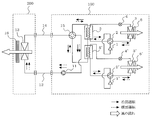
- FIG. 1 is a schematic diagram of a heat pump device according to Embodiment 1 of the present invention.
- the heat pump device according to Embodiment 1 of the present invention includes an outdoor unit 100, an indoor unit 200, and connection pipes 12 and 14.
- the outdoor unit 100 includes a compressor 1, a four-way valve (flow path switching device) 2, an outdoor heat exchanger 3 that is a heat source side heat exchanger, an expansion valve 4, and a heat source side of the cascade heat exchanger 5, and includes a refrigerant. Is composed of a primary side (heat source side) refrigeration cycle through which the refrigerant circulates, a pump 11 having a variable rotation speed as a heat medium transfer means, a four-way valve (flow path switching device) 15, and a load side of the cascade heat exchanger 5. And a secondary side (load side) refrigeration cycle through which the heat medium circulates.
- the indoor unit 200 houses an indoor heat exchanger 13 that is a load-side heat exchanger.
- the outdoor heat exchanger 3 is provided with an outdoor fan 6 that supplies outdoor air
- the indoor heat exchanger 13 is provided with an indoor fan 16 that supplies indoor air.
- the outdoor heat exchanger 3 and the cascade heat exchanger 5 include a micro-channel heat exchanger (flat tube) that has high heat exchange efficiency and a small internal volume of the fluid flow path (that is, the required amount of refrigerant decreases).
- the microchannel heat exchanger is calculated as 4 S / L, where S is the fluid channel cross-sectional area per fluid channel and L is the wetting edge length (the circumferential length of the inner wall surface of the channel). It is a heat exchanger whose equivalent diameter is less than 1 mm.
- water is used as the heat medium of the secondary refrigeration cycle
- a flammable refrigerant or slightly flammable refrigerant
- propane or isobutane is used as the refrigerant of the primary refrigeration cycle.
- V1 and V2 are 0.9. It is set to satisfy ⁇ (V1 / V2) ⁇ 1.1. This reason will be described later.
- the refrigerant flowing out of the outdoor heat exchanger 3 is expanded by the expansion valve 4 and becomes a low-temperature, low-pressure two-phase refrigerant.
- This two-phase refrigerant flows into the heat source side of the cascade heat exchanger 5 acting as an evaporator.
- the cascade heat exchanger 5 performs heat exchange with water circulating in the secondary refrigeration cycle, cools by absorbing heat from the water, and becomes a low-temperature and low-pressure gas refrigerant.
- the gas refrigerant flowing out from the heat source side of the cascade heat exchanger 5 returns to the compressor 1 through the four-way valve 2.
- water absorbed and cooled by the refrigerant in the cascade heat exchanger 5 is discharged by the pump 11 and flows into the indoor heat exchanger 13 through the connection pipe 12.
- the indoor heat exchanger 13 exchanges heat with the room air, absorbs heat from the room air, cools the room, and increases its temperature.
- the water flowing out from the indoor heat exchanger 13 passes through the connection pipe 14 and the four-way valve 15 and flows into the load side of the cascade heat exchanger 5.
- coolant is performed with the cascade heat exchanger 5, and the amount of heat which absorbed heat from indoor air is passed to a refrigerant
- the liquid refrigerant flowing out from the heat source side of the cascade heat exchanger 5 is decompressed by the expansion valve 4 to become a low-temperature / low-pressure two-phase refrigerant.
- This two-phase refrigerant flows into the outdoor heat exchanger 3.
- the outdoor heat exchanger 3 exchanges heat with the outdoor air, absorbs heat from the outdoor air, evaporates itself, and becomes a low-temperature and low-pressure gas refrigerant.
- the gas refrigerant flowing out of the outdoor heat exchanger 3 returns to the compressor 1 through the four-way valve 2.
- the water that has been absorbed by the cascade heat exchanger 5 and is warmed is discharged by the pump 11 and flows into the indoor heat exchanger 13 through the connection pipe 12. Then, the indoor heat exchanger 13 exchanges heat with the room air, radiates heat to the room air, heats the room, and falls itself.
- the water flowing out from the indoor heat exchanger 13 passes through the connection pipe 14 and the four-way valve 15 and flows into the load side of the cascade heat exchanger 5.
- coolant is performed in the cascade heat exchanger 5, and the amount of heat which thermally radiated indoor air is taken from a refrigerant
- the heat pump device uses microchannel heat exchangers having a small internal volume of the fluid flow path for the outdoor heat exchanger 3 and the cascade heat exchanger 5 of the primary refrigeration cycle in which the refrigerant circulates.
- the amount of refrigerant combusted in the combustible refrigerant can be reduced.
- the internal volume V1 of the fluid flow path through which the refrigerant of the outdoor heat exchanger 3 flows and the internal volume V2 of the fluid flow path through which the refrigerant of the cascade heat exchanger 5 flow are 0.9 ⁇ (V1 / V2) ⁇ 1.1.
- the required amount of refrigerant filled in both the cooling operation and the heating operation is substantially equal, and the amount of refrigerant filled in the combustible refrigerant can be greatly reduced. Therefore, it can be configured with an allowable refrigerant filling amount (about 150 g in the case of propane) of European standards (for example, IEC standards).
- an allowable refrigerant filling amount about 150 g in the case of propane
- European standards for example, IEC standards
- V1 / V2 When there is no refrigerant storage tank, if V1 / V2 is 0.9 or less, the internal volume of the fluid flow path through which the refrigerant of the outdoor heat exchanger 3 flows is too small, and the refrigerant is stored in the outdoor heat exchanger 3 during the cooling operation. It cannot be stored, and problems such as liquid return to the compressor 1 occur. Similarly, when V1 / V2 is 1.1 or more, the internal volume of the fluid flow path through which the refrigerant of the cascade heat exchanger 5 flows is excessively small, and the refrigerant cannot be stored in the cascade heat exchanger 5 during heating operation. Problems such as liquid return to the compressor 1 occur.
- the outdoor heat exchanger 3 is configured to have header distributors at the top and bottom like a finless heat exchanger or a corrugated fin tube heat exchanger, thereby eliminating the need for a close contact process between the fin and the tube.
- the vessel can be configured simply.
- the flow path switching is performed using the four-way valves 2, 2 ′, 15 as the flow path switching device, a two-way valve, a three-way valve, or the like may be combined.
- water is used for the heat medium of the secondary side refrigerating cycle, it is not limited to this, An antifreeze etc. may be sufficient.
- FIG. 3 is a schematic diagram of a heat pump device according to Embodiment 2 of the present invention. Since the heat pump device according to the second embodiment is the same as the heat pump device according to the first embodiment except that the four-way valve 15 is configured by four on-off valves 21 to 24 as shown in FIG. Detailed description will be omitted, and only the operation of the secondary refrigeration cycle will be described.
- the pressure loss is small as in the water circuit, and the four-way valves are opened and closed. Even when the necessary pressure difference cannot be obtained, an effect that the opening / closing operation can be performed reliably can be obtained.
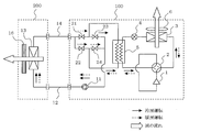
- FIG. 4 is a schematic diagram of a heat pump device according to Embodiment 3 of the present invention.
- the four-way valve 15 is omitted from the heat pump device according to the first embodiment as shown in FIG. 4, and a high-low pressure heat exchanger 7 is provided in the primary refrigeration cycle instead. It is a configuration.
- the liquid refrigerant supercooled by the high / low pressure heat exchanger 7 is expanded by the expansion valve 4 to become a low-temperature / low-pressure two-phase refrigerant.
- This two-phase refrigerant flows into the heat source side of the cascade heat exchanger 5 acting as an evaporator.
- the cascade heat exchanger 5 performs heat exchange with water circulating in the secondary refrigeration cycle, cools by absorbing heat from the water, and becomes a low-temperature and low-pressure gas refrigerant.
- the gas refrigerant flowing out from the heat source side of the cascade heat exchanger 5 flows into the low pressure side of the high and low pressure heat exchanger 7. Then, it is heated by the high / low pressure heat exchanger 7.
- the gas refrigerant superheated by the high / low pressure heat exchanger 7 returns to the compressor 1 through the four-way valve 2.
- the four-way valve 2 of the primary side refrigeration cycle is connected as indicated by a dotted line.
- the gas refrigerant that has become high temperature and high pressure by the compressor 1 passes through the four-way valve 2 and flows into the heat source side of the cascade heat exchanger 5 that acts as a condenser.
- the cascade heat exchanger 5 exchanges heat with the water circulating in the secondary refrigeration cycle, warms it by releasing heat to the water, and condenses itself to become a high-temperature and high-pressure liquid refrigerant.
- the liquid refrigerant flowing out from the heat source side of the cascade heat exchanger 5 is decompressed by the expansion valve 4 to become a low-temperature / low-pressure two-phase refrigerant.
- the two-phase refrigerant flows into the high pressure side of the high / low pressure heat exchanger 7. Then, it is heated by the high / low pressure heat exchanger 7.
- the two-phase refrigerant superheated by the high / low pressure heat exchanger 7 flows into the outdoor heat exchanger 3.
- the outdoor heat exchanger 3 exchanges heat with the outdoor air, absorbs heat from the outdoor air, evaporates itself, and becomes a low-temperature and low-pressure gas refrigerant.
- the gas refrigerant flowing out of the outdoor heat exchanger 3 flows into the low pressure side of the high and low pressure heat exchanger 7 through the four-way valve 2. And it supercools with the high-low pressure heat exchanger 7.
- the gas refrigerant supercooled by the high / low pressure heat exchanger 7 returns to the compressor 1.
- the high-low pressure heat exchanger 7 has a low pressure on both the high-pressure side and the low-pressure side, so that a sufficient temperature difference for heat exchange does not occur and the heat exchange amount becomes extremely small.
- the cascade heat exchanger 5 since the refrigerant and water are always in opposite directions, a high-performance heat pump device with high heat exchange efficiency can be obtained.
- the high-low pressure heat exchanger 7 is provided in the primary side refrigeration cycle, and the intake refrigerant is superheated by the high-low pressure heat exchanger 7 during the cooling operation so that the outlet of the cascade heat exchanger 5 is in a wet state.
- the cascade heat exchanger 5 can be used effectively.
- the refrigeration cycle apparatus of the present invention includes a primary side refrigeration cycle including at least the compressor 1, the outdoor heat exchanger 3, and the expansion valve 4, and a secondary side refrigeration including at least the indoor heat exchanger 13 and the pump 11.
- a heat pump device comprising a cycle and a cascade heat exchanger that exchanges heat between the primary side refrigeration cycle and the secondary side refrigeration cycle
- the outdoor heat exchanger 3 and the cascade heat exchange of the primary side refrigeration cycle in which refrigerant circulates Since the microchannel heat exchanger having a small internal volume of the fluid flow path is used for the vessel 5, the amount of the flammable refrigerant filled can be reduced.
- the primary side refrigeration cycle includes a four-way valve 2, and an internal volume V1 of the fluid flow path through which the refrigerant of the outdoor heat exchanger 3 flows and an internal volume V2 of the fluid flow path through which the refrigerant of the cascade heat exchanger 5 flow are set to 0. Since 9 ⁇ (V1 / V2) ⁇ 1.1 is determined, the required refrigerant filling amount is almost equal in both the cooling operation and the heating operation, and the refrigerant filling amount of the flammable refrigerant is greatly reduced. be able to. Therefore, it can be configured with an allowable refrigerant filling amount (about 150 g in the case of propane) of European standards (for example, IEC standards).
Abstract
Description
実施の形態1.
図1は、本発明の実施の形態1に係るヒートポンプ装置の概略図である。
本発明の実施の形態1に係るヒートポンプ装置は、室外ユニット100と、室内ユニット200と、接続配管12、14と、で構成されている。
また、室内ユニット200は、負荷側熱交換器である室内熱交換器13が収納されている。
また、室外熱交換器3には室外空気を供給する室外送風機6、室内熱交換器13には室内空気を供給する室内送風機16が、それぞれ設けられている。
[冷房運転]
まず、冷房運転時は、一次側冷凍サイクルの四方弁2および四方弁15が実線のように接続される。
圧縮機1により高温・高圧となったガス冷媒は、四方弁2を通り、室外熱交換器3に流入する。そして、室外熱交換器3で室外空気と熱交換を行い、室外空気へ放熱し、自らは凝縮され、高温・高圧の液冷媒となる。室外熱交換器3から流出した冷媒は、膨張弁4により膨張させられて低温・低圧の二相冷媒となる。この二相冷媒は蒸発器として作用するカスケード熱交換器5の熱源側に流入する。そして、カスケード熱交換器5で二次側冷凍サイクルを循環する水と熱交換を行い、水から吸熱することで冷却し、自らは低温・低圧のガス冷媒となる。その後、カスケード熱交換器5の熱源側から流出したガス冷媒は、四方弁2を介して圧縮機1へ戻る。
つぎに、暖房運転時は、一次側冷凍サイクルの四方弁2および四方弁15が点線のように接続される。
圧縮機1により高温・高圧となったガス冷媒は、四方弁2を通り、凝縮器として作用するカスケード熱交換器5の熱源側に流入する。そして、カスケード熱交換器5で二次側冷凍サイクルを循環する水と熱交換を行い、水に放熱することで暖め、自らは凝縮され、高温・高圧の液冷媒となる。カスケード熱交換器5の熱源側から流出した液冷媒は、膨張弁4により減圧されて低温・低圧の二相冷媒となる。この二相冷媒は室外熱交換器3に流入する。そして、室外熱交換器3で室外空気と熱交換を行い、室外空気から吸熱し、自らは蒸発し、低温・低圧のガス冷媒となる。その後、室外熱交換器3から流出したガス冷媒は、四方弁2を介して圧縮機1へ戻る。
そのため、欧州規格(例えば、IEC規格)の許容冷媒封入量(プロパンの場合、約150g)未満で構成できる。また、冷房運転、暖房運転のいずれにおいても必要な冷媒封入量がほぼ等しいため、両運転時の冷媒量差を吸収するための冷媒貯留タンク(図示省略)が不要となる。
以上より、安全性および設置自由度の高いヒートポンプ装置を得ることができる。
また、室外熱交換器3を、フィンレス熱交換器、またはコルゲートフィンチューブ熱交換器のように上下にヘッダー分配器を有する構成とすることで、フィンと管との密着工程が不要となり、熱交換器をシンプルに構成できる。
また、流路切替装置として四方弁2、2’、15を用いて流路切り替えを行っているが、二方弁、三方弁などを組み合わせて行ってもよい。
また、二次側冷凍サイクルの熱媒体には水が用いられているが、それに限定されず、不凍液などでもよい。
以下、本実施の形態2について説明するが、本実施の形態1との相違点を中心に説明し、重複するものについては省略する。また、本実施の形態1と同一部分には、同一符号を付してある。
図3は、本発明の実施の形態2に係るヒートポンプ装置の概略図である。
本実施の形態2に係るヒートポンプ装置は、図3に示すように四方弁15を4つの開閉弁21~24で構成した以外は、実施の形態1に係るヒートポンプ装置の構成と同じであるため、詳細な説明は省略し、二次側冷凍サイクルの動作のみ説明する。
冷房運転時の二次側冷凍サイクルでは、カスケード熱交換器5で冷媒に吸熱され冷却された水が、ポンプ11によって吐出され、接続配管12を通って室内熱交換器13に流入する。そして、室内熱交換器13で室内空気と熱交換を行い、室内空気から吸熱して室内を冷房し、自らは温度上昇する。室内熱交換器13から流出した水は、接続配管14および開閉弁22を通り、カスケード熱交換器5の負荷側に流入する。そして、カスケード熱交換器5で冷媒と熱交換を行い、室内空気から吸熱した分の熱量を冷媒へ渡し、冷却される。その後、カスケード熱交換器5の負荷側から流出した水は、開閉弁23を介してポンプ11へ戻る。
つぎに、暖房運転の二次側冷凍サイクルでは、カスケード熱交換器5で冷媒から吸熱し暖められた水が、ポンプ11によって吐出され、接続配管12を通って室内熱交換器13に流入する。そして、室内熱交換器13で室内空気と熱交換を行い、室内空気に放熱して室内を暖房し、自らは温度低下する。室内熱交換器13から流出した水は、接続配管14および開閉弁21を通り、カスケード熱交換器5の負荷側に流入する。そして、カスケード熱交換器5で冷媒と熱交換を行い、室内空気に放熱した分の熱量を冷媒から奪い、加熱される。その後、カスケード熱交換器5の負荷側から流出した水は、開閉弁24を介してポンプ11へ戻る。
以下、本実施の形態3について説明するが、本実施の形態1との相違点を中心に説明し、重複するものについては省略する。また、本実施の形態1と同一部分には、同一符号を付してある。
図4は、本発明の実施の形態3に係るヒートポンプ装置の概略図である。
本実施の形態3に係るヒートポンプ装置は、図4に示すように実施の形態1に係るヒートポンプ装置から四方弁15を省略し、その代わりに一次側冷凍サイクルに高低圧熱交換器7を設けた構成である。これにより、カスケード熱交換器5での水および冷媒の流れは、暖房運転時には対向流となるが、冷房運転時には並行流となる。なお、それ以外の構成は実施の形態1および実施の形態2よりも単純となるため、詳細な説明は省略し、一次側冷凍サイクルの動作のみ説明する。
まず、冷房運転時は、一次側冷凍サイクルの四方弁2が実線のように接続される。
圧縮機1により高温・高圧となったガス冷媒は、四方弁2を通り、室外熱交換器3に流入する。そして、室外熱交換器3で室外空気と熱交換を行い、室外空気へ放熱し、自らは凝縮され、高温・高圧の液冷媒となる。室外熱交換器3から流出した液冷媒は、高低圧熱交換器7の高圧側に流入する。そして、高低圧熱交換器7で過冷却される。高低圧熱交換器7で過冷却された液冷媒は、膨張弁4により膨張させられて低温・低圧の二相冷媒となる。この二相冷媒は蒸発器として作用するカスケード熱交換器5の熱源側に流入する。そして、カスケード熱交換器5で二次側冷凍サイクルを循環する水と熱交換を行い、水から吸熱することで冷却し、自らは低温・低圧のガス冷媒となる。その後、カスケード熱交換器5の熱源側から流出したガス冷媒は、高低圧熱交換器7の低圧側に流入する。そして、高低圧熱交換器7で過熱される。高低圧熱交換器7で過熱されたガス冷媒は、四方弁2を介して圧縮機1へ戻る。
つぎに、暖房運転時は、一次側冷凍サイクルの四方弁2が点線のように接続される。
圧縮機1により高温・高圧となったガス冷媒は、四方弁2を通り、凝縮器として作用するカスケード熱交換器5の熱源側に流入する。そして、カスケード熱交換器5で二次側冷凍サイクルを循環する水と熱交換を行い、水に放熱することで暖め、自らは凝縮され、高温・高圧の液冷媒となる。カスケード熱交換器5の熱源側から流出した液冷媒は、膨張弁4により減圧されて低温・低圧の二相冷媒となる。この二相冷媒は高低圧熱交換器7の高圧側に流入する。そして、高低圧熱交換器7で過熱される。高低圧熱交換器7で過熱された二相冷媒は、室外熱交換器3に流入する。そして、室外熱交換器3で室外空気と熱交換を行い、室外空気から吸熱し、自らは蒸発し、低温・低圧のガス冷媒となる。その後、室外熱交換器3から流出したガス冷媒は、四方弁2を介して高低圧熱交換器7の低圧側に流入する。そして、高低圧熱交換器7で過冷却される。高低圧熱交換器7で過冷却されたガス冷媒は、圧縮機1へ戻る。
そのため、欧州規格(例えば、IEC規格)の許容冷媒封入量(プロパンの場合、約150g)未満で構成できる。また、冷房運転、暖房運転のいずれにおいても必要な冷媒封入量がほぼ等しいため、両運転時の冷媒量差を吸収するための冷媒貯留タンクが不要となる。
以上より、安全性および設置自由度の高いヒートポンプ装置を得ることができる。
Claims (8)
- 圧縮機、熱源側熱交換器、膨張弁、および、カスケード熱交換器の熱源側が順次接続され、冷媒が循環する熱源側冷凍サイクルと、
熱媒体搬送手段、負荷側熱交換器、および、前記カスケード熱交換器の負荷側が順次接続され、熱媒体が循環する負荷側冷凍サイクルと、で構成され、
前記熱源側熱交換器および前記カスケード熱交換器は、流体流路断面積をS、濡れ縁長さをLとした場合、4S/Lで算出される相当直径が1mm未満である
ことを特徴とするヒートポンプ装置。 - 前記熱源側冷凍サイクルは流路切替装置を備え、
前記熱源側熱交換器の冷媒が流れる流体流路の内容積をV1、および前記カスケード熱交換器の冷媒が流れる流体流路の内容積をV2とした場合、V1およびV2は、0.9<(V1/V2)<1.1を満たすように定められている
ことを特徴とする請求項1に記載のヒートポンプ装置。 - 前記冷媒には可燃性冷媒または微燃性冷媒が用いられている
ことを特徴とする請求項1または2に記載のヒートポンプ装置。 - 前記熱源側冷凍サイクルを二つ以上有し、前記負荷側冷凍サイクルに対して並列に接続した
ことを特徴とする請求項1~3のいずれか一項に記載のヒートポンプ装置。 - 前記負荷側冷凍サイクルに流路切替装置を設け、
冷房運転時と暖房運転時のいずれにおいても、
前記カスケード熱交換器での前記冷媒と前記熱媒体との流れが対向流となるように構成され、かつ、前記負荷側熱交換器での前記熱媒体と空気との流れが対向流となるように構成された
ことを特徴とする請求項1~4のいずれか一項に記載のヒートポンプ装置。 - 前記流路切替装置は、
四方弁または四つの開閉弁で構成されている
ことを特徴とする請求項5に記載のヒートポンプ装置。 - 前記熱源側冷凍サイクルに高低圧熱交換器を設け、
暖房運転時において、
前記カスケード熱交換器での前記冷媒と前記熱媒体との流れが対向流となるように構成された
ことを特徴とする請求項1~4のいずれか一項に記載のヒートポンプ装置。 - 前記熱源側熱交換器は、上下にヘッダー分配器を有する
ことを特徴とする請求項1~7のいずれか一項に記載のヒートポンプ装置。
Priority Applications (5)
| Application Number | Priority Date | Filing Date | Title |
|---|---|---|---|
| CN201480073844.7A CN105940276A (zh) | 2014-01-23 | 2014-01-23 | 热泵装置 |
| US15/108,664 US10605498B2 (en) | 2014-01-23 | 2014-01-23 | Heat pump apparatus |
| EP14879730.1A EP3098540B1 (en) | 2014-01-23 | 2014-01-23 | Heat pump apparatus |
| PCT/JP2014/051429 WO2015111175A1 (ja) | 2014-01-23 | 2014-01-23 | ヒートポンプ装置 |
| JP2015558653A JPWO2015111175A1 (ja) | 2014-01-23 | 2014-01-23 | ヒートポンプ装置 |
Applications Claiming Priority (1)
| Application Number | Priority Date | Filing Date | Title |
|---|---|---|---|
| PCT/JP2014/051429 WO2015111175A1 (ja) | 2014-01-23 | 2014-01-23 | ヒートポンプ装置 |
Publications (1)
| Publication Number | Publication Date |
|---|---|
| WO2015111175A1 true WO2015111175A1 (ja) | 2015-07-30 |
Family
ID=53681005
Family Applications (1)
| Application Number | Title | Priority Date | Filing Date |
|---|---|---|---|
| PCT/JP2014/051429 WO2015111175A1 (ja) | 2014-01-23 | 2014-01-23 | ヒートポンプ装置 |
Country Status (5)
| Country | Link |
|---|---|
| US (1) | US10605498B2 (ja) |
| EP (1) | EP3098540B1 (ja) |
| JP (1) | JPWO2015111175A1 (ja) |
| CN (1) | CN105940276A (ja) |
| WO (1) | WO2015111175A1 (ja) |
Cited By (6)
| Publication number | Priority date | Publication date | Assignee | Title |
|---|---|---|---|---|
| CN108534384A (zh) * | 2018-03-08 | 2018-09-14 | 约克广州空调冷冻设备有限公司 | 一种风冷冷水机组系统及操作方法 |
| JP6698951B1 (ja) * | 2019-02-27 | 2020-05-27 | 三菱電機株式会社 | 空気調和装置 |
| JP2020153632A (ja) * | 2019-03-22 | 2020-09-24 | 三菱重工サーマルシステムズ株式会社 | チラーユニット |
| JP2020159585A (ja) * | 2019-03-25 | 2020-10-01 | 三菱重工サーマルシステムズ株式会社 | チラーユニット |
| JP2020201012A (ja) * | 2019-06-12 | 2020-12-17 | ダイキン工業株式会社 | 空調機 |
| JP2020201013A (ja) * | 2019-06-12 | 2020-12-17 | ダイキン工業株式会社 | 空調機 |
Families Citing this family (8)
| Publication number | Priority date | Publication date | Assignee | Title |
|---|---|---|---|---|
| US10775056B2 (en) * | 2014-09-08 | 2020-09-15 | United Maintenance, Inc. | Natatorium dehumidifier |
| DE212016000038U1 (de) * | 2015-01-09 | 2017-08-11 | Trane International Inc. | Wärmepumpe |
| MX2019015339A (es) * | 2017-06-21 | 2020-02-19 | Honeywell Int Inc | Sistemas y metodos de refrigeracion. |
| KR102641646B1 (ko) * | 2017-06-21 | 2024-02-28 | 허니웰 인터내셔날 인코포레이티드 | 냉각 시스템 및 방법 |
| JP2021531443A (ja) * | 2018-07-09 | 2021-11-18 | ハネウェル・インターナショナル・インコーポレーテッドHoneywell International Inc. | 冷凍システムおよび方法 |
| WO2020071300A1 (ja) * | 2018-10-02 | 2020-04-09 | ダイキン工業株式会社 | 冷凍サイクル装置 |
| JP2021055958A (ja) * | 2019-09-30 | 2021-04-08 | ダイキン工業株式会社 | 冷凍装置 |
| US20230375230A1 (en) * | 2022-05-21 | 2023-11-23 | Honeywell International Inc. | Nonflammable refrigerants having low gwp, and systems for and methods of providing refrigeration |
Citations (11)
| Publication number | Priority date | Publication date | Assignee | Title |
|---|---|---|---|---|
| JPH06241596A (ja) * | 1993-02-18 | 1994-08-30 | Toshiba Corp | 空気調和装置 |
| JPH085197A (ja) * | 1994-06-24 | 1996-01-12 | Nippondenso Co Ltd | 冷媒凝縮器 |
| JPH11101517A (ja) * | 1997-09-29 | 1999-04-13 | Matsushita Refrig Co Ltd | 冷凍システム |
| JP2001194081A (ja) * | 1999-03-08 | 2001-07-17 | Denso Corp | 放熱器又は蒸発器用のチューブ |
| JP2001248922A (ja) * | 1999-12-28 | 2001-09-14 | Daikin Ind Ltd | 冷凍装置 |
| JP2002295915A (ja) * | 2001-03-30 | 2002-10-09 | Mitsubishi Electric Corp | 空気調和機 |
| JP2003004396A (ja) | 2001-06-27 | 2003-01-08 | Hitachi Ltd | 熱交換器および冷凍空調装置 |
| JP2004239503A (ja) * | 2003-02-05 | 2004-08-26 | Sanyo Electric Co Ltd | 熱交換器 |
| JP2010096372A (ja) * | 2008-10-15 | 2010-04-30 | Hitachi Cable Ltd | 二酸化炭素冷媒用の内部熱交換器 |
| JP2013044469A (ja) * | 2011-08-24 | 2013-03-04 | Panasonic Corp | 冷凍空調装置 |
| JP2013148328A (ja) * | 2011-12-20 | 2013-08-01 | Daikin Industries Ltd | 冷凍装置 |
Family Cites Families (34)
| Publication number | Priority date | Publication date | Assignee | Title |
|---|---|---|---|---|
| US5044172A (en) * | 1987-10-30 | 1991-09-03 | Takenaka Corporation | Air conditioning apparatus |
| JP3414825B2 (ja) * | 1994-03-30 | 2003-06-09 | 東芝キヤリア株式会社 | 空気調和装置 |
| US6094925A (en) * | 1999-01-29 | 2000-08-01 | Delaware Capital Formation, Inc. | Crossover warm liquid defrost refrigeration system |
| JP2002089978A (ja) * | 2000-09-11 | 2002-03-27 | Daikin Ind Ltd | ペア型の冷凍装置およびマルチ型の冷凍装置 |
| GB0201598D0 (en) * | 2002-01-25 | 2002-03-13 | Delphi Tech Inc | Heating ventilation air conditioned system |
| US6694773B1 (en) * | 2003-01-29 | 2004-02-24 | Calsonickansei North America, Inc. | Condenser system with nondetachably coupled receiver |
| US7415838B2 (en) * | 2005-02-26 | 2008-08-26 | Lg Electronics Inc | Second-refrigerant pump driving type air conditioner |
| JP3948475B2 (ja) * | 2005-09-20 | 2007-07-25 | ダイキン工業株式会社 | 空気調和装置 |
| JP4165566B2 (ja) * | 2006-01-25 | 2008-10-15 | ダイキン工業株式会社 | 空気調和装置 |
| JP4898300B2 (ja) * | 2006-05-30 | 2012-03-14 | 昭和電工株式会社 | エバポレータ |
| US8206204B2 (en) * | 2006-09-21 | 2012-06-26 | Ford Global Technologies, Llc | Control unit heat management |
| US9163866B2 (en) * | 2006-11-30 | 2015-10-20 | Lennox Industries Inc. | System pressure actuated charge compensator |
| JP5125116B2 (ja) * | 2007-01-26 | 2013-01-23 | ダイキン工業株式会社 | 冷凍装置 |
| JP4948374B2 (ja) * | 2007-11-30 | 2012-06-06 | 三菱電機株式会社 | 冷凍サイクル装置 |
| JP5178841B2 (ja) * | 2008-10-29 | 2013-04-10 | 三菱電機株式会社 | 空気調和装置 |
| US8839640B2 (en) | 2009-10-27 | 2014-09-23 | Mitsubishi Electric Corporation | Air-conditioning apparatus |
| JP2011112312A (ja) * | 2009-11-30 | 2011-06-09 | Hitachi Ltd | 移動体の熱サイクルシステム |
| JP5581886B2 (ja) * | 2010-08-11 | 2014-09-03 | 株式会社日立製作所 | 車両用空調システム |
| WO2012066763A1 (ja) * | 2010-11-15 | 2012-05-24 | 三菱電機株式会社 | 冷凍装置 |
| JP5709978B2 (ja) * | 2011-03-28 | 2015-04-30 | 三菱電機株式会社 | 空気調和装置 |
| US9038404B2 (en) * | 2011-04-19 | 2015-05-26 | Liebert Corporation | High efficiency cooling system |
| CN103797317B (zh) * | 2011-09-13 | 2016-08-17 | 三菱电机株式会社 | 热泵装置和热泵装置的控制方法 |
| JP5617860B2 (ja) * | 2012-03-28 | 2014-11-05 | ダイキン工業株式会社 | 冷凍装置 |
| GB2524673B (en) * | 2013-01-07 | 2019-08-21 | Mitsubishi Electric Corp | Heat pump system |
| JP2015068620A (ja) * | 2013-09-30 | 2015-04-13 | ダイキン工業株式会社 | 空気調和機 |
| WO2015057297A1 (en) * | 2013-10-17 | 2015-04-23 | Carrier Corporation | Operation of a cascade air conditioning system with two-phase loop |
| FR3016206B1 (fr) * | 2014-01-08 | 2016-02-05 | Alstom Transport Sa | Dispositif de climatisation d'un compartiment, notamment pour un vehicule ferroviaire |
| WO2015132951A1 (ja) * | 2014-03-07 | 2015-09-11 | 三菱電機株式会社 | 冷凍装置 |
| CN106104170B (zh) * | 2014-03-17 | 2019-10-25 | 三菱电机株式会社 | 制冷循环装置 |
| US9777950B2 (en) * | 2014-04-01 | 2017-10-03 | Lennox Industries Inc. | Reversible heat pump with cycle enhancements |
| US9970689B2 (en) * | 2014-09-22 | 2018-05-15 | Liebert Corporation | Cooling system having a condenser with a micro-channel cooling coil and sub-cooler having a fin-and-tube heat cooling coil |
| KR101708642B1 (ko) * | 2015-09-11 | 2017-02-21 | 엘지전자 주식회사 | 공기조화기의 쿨링리시버 및 공기조화기 |
| US10907863B2 (en) * | 2016-01-06 | 2021-02-02 | Honeywell International Inc. | Air conditioning systems and methods |
| US10775070B2 (en) * | 2017-06-23 | 2020-09-15 | Lennox Industries Inc. | Method for solving charge imbalance in existing split heat pump |
-
2014
- 2014-01-23 JP JP2015558653A patent/JPWO2015111175A1/ja active Pending
- 2014-01-23 US US15/108,664 patent/US10605498B2/en active Active
- 2014-01-23 EP EP14879730.1A patent/EP3098540B1/en active Active
- 2014-01-23 CN CN201480073844.7A patent/CN105940276A/zh active Pending
- 2014-01-23 WO PCT/JP2014/051429 patent/WO2015111175A1/ja active Application Filing
Patent Citations (11)
| Publication number | Priority date | Publication date | Assignee | Title |
|---|---|---|---|---|
| JPH06241596A (ja) * | 1993-02-18 | 1994-08-30 | Toshiba Corp | 空気調和装置 |
| JPH085197A (ja) * | 1994-06-24 | 1996-01-12 | Nippondenso Co Ltd | 冷媒凝縮器 |
| JPH11101517A (ja) * | 1997-09-29 | 1999-04-13 | Matsushita Refrig Co Ltd | 冷凍システム |
| JP2001194081A (ja) * | 1999-03-08 | 2001-07-17 | Denso Corp | 放熱器又は蒸発器用のチューブ |
| JP2001248922A (ja) * | 1999-12-28 | 2001-09-14 | Daikin Ind Ltd | 冷凍装置 |
| JP2002295915A (ja) * | 2001-03-30 | 2002-10-09 | Mitsubishi Electric Corp | 空気調和機 |
| JP2003004396A (ja) | 2001-06-27 | 2003-01-08 | Hitachi Ltd | 熱交換器および冷凍空調装置 |
| JP2004239503A (ja) * | 2003-02-05 | 2004-08-26 | Sanyo Electric Co Ltd | 熱交換器 |
| JP2010096372A (ja) * | 2008-10-15 | 2010-04-30 | Hitachi Cable Ltd | 二酸化炭素冷媒用の内部熱交換器 |
| JP2013044469A (ja) * | 2011-08-24 | 2013-03-04 | Panasonic Corp | 冷凍空調装置 |
| JP2013148328A (ja) * | 2011-12-20 | 2013-08-01 | Daikin Industries Ltd | 冷凍装置 |
Cited By (12)
| Publication number | Priority date | Publication date | Assignee | Title |
|---|---|---|---|---|
| CN108534384A (zh) * | 2018-03-08 | 2018-09-14 | 约克广州空调冷冻设备有限公司 | 一种风冷冷水机组系统及操作方法 |
| JP6698951B1 (ja) * | 2019-02-27 | 2020-05-27 | 三菱電機株式会社 | 空気調和装置 |
| WO2020174619A1 (ja) * | 2019-02-27 | 2020-09-03 | 三菱電機株式会社 | 空気調和装置 |
| US11906191B2 (en) | 2019-02-27 | 2024-02-20 | Mitsubishi Electric Corporation | Air-conditioning apparatus |
| JP2020153632A (ja) * | 2019-03-22 | 2020-09-24 | 三菱重工サーマルシステムズ株式会社 | チラーユニット |
| JP7258616B2 (ja) | 2019-03-22 | 2023-04-17 | 三菱重工サーマルシステムズ株式会社 | チラーユニット |
| JP2020159585A (ja) * | 2019-03-25 | 2020-10-01 | 三菱重工サーマルシステムズ株式会社 | チラーユニット |
| JP7258618B2 (ja) | 2019-03-25 | 2023-04-17 | 三菱重工サーマルシステムズ株式会社 | チラーユニット |
| JP2020201012A (ja) * | 2019-06-12 | 2020-12-17 | ダイキン工業株式会社 | 空調機 |
| JP2020201013A (ja) * | 2019-06-12 | 2020-12-17 | ダイキン工業株式会社 | 空調機 |
| WO2020250953A1 (ja) * | 2019-06-12 | 2020-12-17 | ダイキン工業株式会社 | 空調機 |
| JP7469583B2 (ja) | 2019-06-12 | 2024-04-17 | ダイキン工業株式会社 | 空調機 |
Also Published As
| Publication number | Publication date |
|---|---|
| CN105940276A (zh) | 2016-09-14 |
| EP3098540A1 (en) | 2016-11-30 |
| US10605498B2 (en) | 2020-03-31 |
| EP3098540B1 (en) | 2020-10-07 |
| JPWO2015111175A1 (ja) | 2017-03-23 |
| US20160320105A1 (en) | 2016-11-03 |
| EP3098540A4 (en) | 2017-10-11 |
Similar Documents
| Publication | Publication Date | Title |
|---|---|---|
| WO2015111175A1 (ja) | ヒートポンプ装置 | |
| JP5752148B2 (ja) | 空気調和装置 | |
| JP5602243B2 (ja) | 空気調和機 | |
| US20140230477A1 (en) | Hot water supply air conditioning system | |
| JP5183804B2 (ja) | 冷凍サイクル装置、空気調和装置 | |
| WO2015132959A1 (ja) | 空気調和装置 | |
| WO1998006983A1 (fr) | Conditionneur d'air | |
| WO2015125743A1 (ja) | 空気調和装置 | |
| US20150075199A1 (en) | Air-Conditioning/Hot-Water Supply System | |
| JP5908183B1 (ja) | 空気調和装置 | |
| WO2014132378A1 (ja) | 空気調和装置 | |
| WO2016071955A1 (ja) | 空気調和装置 | |
| JP2017161182A (ja) | ヒートポンプ装置 | |
| JPWO2015140885A1 (ja) | 冷凍サイクル装置 | |
| EP2578966A1 (en) | Refrigeration device and cooling and heating device | |
| JP2013083439A5 (ja) | ||
| JPWO2013093977A1 (ja) | 空気調和装置 | |
| JP3063348B2 (ja) | 間接冷媒空調装置、間接冷媒空調装置用の脱着型熱交換器及び間接冷媒空調方法 | |
| WO2016038659A1 (ja) | 冷凍サイクル装置 | |
| WO2019198175A1 (ja) | 冷凍サイクル装置 | |
| JP2015218954A (ja) | 冷凍サイクル装置 | |
| JP2001355924A (ja) | 空気調和機 | |
| KR101658021B1 (ko) | 이원냉동사이클을 이용한 히트펌프 시스템 | |
| JP2017161164A (ja) | 空調給湯システム | |
| JP5826722B2 (ja) | 二元冷凍装置 |
Legal Events
| Date | Code | Title | Description |
|---|---|---|---|
| 121 | Ep: the epo has been informed by wipo that ep was designated in this application |
Ref document number: 14879730 Country of ref document: EP Kind code of ref document: A1 |
|
| ENP | Entry into the national phase |
Ref document number: 2015558653 Country of ref document: JP Kind code of ref document: A |
|
| WWE | Wipo information: entry into national phase |
Ref document number: 15108664 Country of ref document: US |
|
| REEP | Request for entry into the european phase |
Ref document number: 2014879730 Country of ref document: EP |
|
| WWE | Wipo information: entry into national phase |
Ref document number: 2014879730 Country of ref document: EP |
|
| NENP | Non-entry into the national phase |
Ref country code: DE |