WO2015099145A1 - 蛍光体、及び蛍光体の製造方法 - Google Patents
蛍光体、及び蛍光体の製造方法 Download PDFInfo
- Publication number
- WO2015099145A1 WO2015099145A1 PCT/JP2014/084590 JP2014084590W WO2015099145A1 WO 2015099145 A1 WO2015099145 A1 WO 2015099145A1 JP 2014084590 W JP2014084590 W JP 2014084590W WO 2015099145 A1 WO2015099145 A1 WO 2015099145A1
- Authority
- WO
- WIPO (PCT)
- Prior art keywords
- phosphor
- afterglow
- group
- element selected
- composition
- Prior art date
- Legal status (The legal status is an assumption and is not a legal conclusion. Google has not performed a legal analysis and makes no representation as to the accuracy of the status listed.)
- Ceased
Links
Images





Classifications
-
- C—CHEMISTRY; METALLURGY
- C09—DYES; PAINTS; POLISHES; NATURAL RESINS; ADHESIVES; COMPOSITIONS NOT OTHERWISE PROVIDED FOR; APPLICATIONS OF MATERIALS NOT OTHERWISE PROVIDED FOR
- C09K—MATERIALS FOR MISCELLANEOUS APPLICATIONS, NOT PROVIDED FOR ELSEWHERE
- C09K11/00—Luminescent materials, e.g. electroluminescent or chemiluminescent
- C09K11/08—Luminescent materials, e.g. electroluminescent or chemiluminescent containing inorganic luminescent materials
Definitions
- the present invention relates to a phosphor and a method for producing the phosphor.
- Phosphorescent long afterglow phosphors temporarily trap electrons, holes, and other carriers generated by external energy (eg, ultraviolet light, purple light, etc.) into defects in the crystal, and the trapped carriers The light is gradually released by the thermal energy of the air temperature, and recombines at the emission center to show long-lasting emission.
- This long afterglow phosphor stores sunlight energy during the day, light energy from room lighting, etc., and shines at night or after extinguishing the light, so that it can be used as a visible nocturnal paint. Therefore, the long afterglow phosphor is used for safety signs and evacuation guidance systems.
- white LEDs Light Emitting Diodes
- White LEDs having characteristics such as long-term stability, energy saving, and high emission quantum efficiency have been frequently used as solid-state lighting devices in place of the fluorescent lamps.
- White LEDs that are commonly used are composed of a combination of a blue LED and a yellow phosphor, or a combination of a blue LED, a red phosphor, and a green phosphor. That is, the light from the white LED includes only blue light as light having the shortest wavelength, and does not include ultraviolet rays.
- Ce 3+ : YAG phosphor As a phosphor that absorbs light in the blue region, a Ce 3 + -added A 3 B 2 C 3 O 12 garnet phosphor (for example, Ce 3+ : Y 3 Al 2 Al 3 O 12 , hereinafter referred to as Ce 3+ : YAG phosphor). Is known).
- the Ce 3+ : YAG phosphor absorbs light in the blue region and exhibits yellow light emission with high quantum efficiency. Therefore, the phosphor constituting the white LED (that is, the yellow phosphor used in combination with the blue LED) ).
- Ce 3+ : YAG does not exhibit afterglow characteristics due to blue light excitation.
- Ce 3+ : YAGG was found to have a very low afterglow intensity (afterglow luminance) although it exhibited afterglow characteristics when the blue light was blocked after being excited with blue light.
- an object of the present invention is to provide a phosphor excellent in long afterglow characteristics by ultraviolet excitation and excellent in long afterglow characteristics by blue light excitation, and a method for producing the same.
- composition formula (1) A 3 B 2 C 3 O 12 (1) (Where A is (i) at least one element selected from the group consisting of Mg, Ca, Sr, La, Gd, Tb, Lu, and Y, and (ii) Ce. B is at least one element selected from the group consisting of Al, Ga, Sc, In, Mg, Lu, and Y; C is at least one element selected from the group consisting of Si, Ge, Al, and Ga).
- At least one metal element selected from the group consisting of Ti, V, Cr, Mn, Fe, Co, Ni, Cu, Zn, Zr, Hf, Si, Yb, Eu, Pr, and Tb is doped.
- Item 3. The phosphor according to Item 1 or 2, wherein the molar ratio of the element (i) to the (ii) Ce is 0.9999: 0.0001 to 0.95: 0.05. 4).
- the phosphor according to any one of Items 1 to 3, which is used for phosphorescent phosphors, white LEDs, phosphorescent ceramics, phosphorescent resins, phosphorescent paints, phosphorescent evacuation guidance systems, or bioimaging markers. 5.
- Fluorescence doped with at least one metal element selected from the group consisting of Ti, V, Cr, Mn, Fe, Co, Ni, Cu, Zn, Zr, Hf, Si, Yb, Eu, Pr, and Tb A method for manufacturing a body, (1) Step 1 of preparing a composition containing the element-containing compound (B), B-element-containing compound, C-element-containing compound, Ce-containing compound and the metal-element-containing compound, and (2) 1200 of the composition. Heating process at ⁇ 1800 °C 2 In order.
- long afterglow refers to a long period of time (eg, several) even if the excitation light (eg, ultraviolet light, violet light, blue light, etc.) is irradiated and then the excitation light is cut off (stopped).
- the excitation light eg, ultraviolet light, violet light, blue light, etc.
- Min. To several tens of hours or more refers to continuous light emission, and can be clearly distinguished from the time scale of light emission (ns to ms) indicated by the electronic transition of atoms.
- the phosphor having the long afterglow function is also referred to as “long afterglow phosphor”, and the phosphor of the present invention is a long afterglow phosphor.
- the center wavelength (emission peak) of afterglow is about 480 to 700 nm (green to red).
- phosphorescence means storing (collecting or trapping) carriers such as electrons and holes so as to accumulate (accumulate) light.
- the carrier is generated by external energy such as ultraviolet light, purple light, and blue light, is captured by the trap, and emits light by being released by the thermal energy of the outside air.
- blue light refers to visible light having a wavelength of 400 to 460 nm unless otherwise specified.
- ultraviolet light means ultraviolet light having a wavelength of 200 to 380 nm unless otherwise specified.
- room temperature means that the air temperature is 10 to 30 ° C. unless otherwise specified.
- the phosphor of the present invention has the following composition formula (1): A 3 B 2 C 3 O 12 (1) (Where A is (i) at least one element selected from the group consisting of Mg, Ca, Sr, La, Gd, Tb, Lu, and Y, and (ii) Ce. B is at least one element selected from the group consisting of Al, Ga, Sc, In, Mg, Lu, and Y; C is at least one element selected from the group consisting of Si, Ge, Al, and Ga). At least one metal element selected from the group consisting of Ti, V, Cr, Mn, Fe, Co, Ni, Cu, Zn, Zr, Hf, Si, Yb, Eu, Pr, and Tb is doped. It is characterized by.
- the phosphor of the present invention having the above-described characteristics can be obtained by, in particular, ultraviolet excitation by doping a specific garnet crystal phosphor containing a Ce element with a specific metal element (the specific metal element is also referred to as an M element). Excellent long afterglow characteristics and excellent long afterglow characteristics by blue light excitation.
- the phosphor of the present invention is also excellent in water resistance.
- the phosphor of the present invention is also referred to as Ce and a specific metal element co-added garnet crystal phosphor.
- a schematic diagram of the garnet crystal structure and occupied cations is shown in FIG.
- a composition of a general garnet crystal structure (garnet structure) is represented by the composition formula (1): A 3 B 2 C 3 O 12 .
- the cation of the element (A element) represented by A in the above formula (1) occupies a dodecahedron site, and the cation of the element (B element) represented by B in the above formula (1) occupies an octahedral site.
- the cation of the element (C element) represented by C in the above formula (1) occupies a tetrahedral site.
- the phosphor of the present invention is a phosphor obtained by co-adding Ce and M elements in the garnet crystal as a base crystal.
- Ce of A in the above formula (1) means that it contains Ce 3+ as the emission center, and this Ce 3+ occupies a dodecahedron site.
- the cations of the M element mainly occupy octahedral sites in many cases.
- the garnet structure in the phosphor of the present invention may have a solid solution region.
- lattice defects and antisite defects occur in the crystal, and a slight composition ratio deviation may occur with respect to the above formula (1) (that is, the phosphor of the present invention has the above formula (1)).
- the present invention may have a non-stoichiometric composition (which may have a non-stoichiometric (non-chemical) stoichiometric composition).
- the crystal structure of the phosphor of the present invention can be confirmed by an X-ray diffraction method or the like.
- the element A is (i) at least one element selected from the group consisting of Mg, Ca, Sr, La, Gd, Tb, Lu, and Y, and (ii) Ce.
- the cation of A (the cation of the element (i) and the cation of (ii) Ce) is in the 8-coordinate position and occupies a dodecahedron site (the site is also referred to as A site).
- At least one element selected from the group consisting of Lu, Gd and Y is preferable, and Y is more preferable.
- Ce 3+ has strong broad absorption due to 4f-5d permissible transition and high luminous efficiency. Further, the Ce 3+ 5d level is reduced in energy by a centroid shift due to the electron cloud expansion effect, and is split into a plurality of levels in the host structure due to the influence of the crystal field.
- FIG. 2 shows changes in the band structure depending on the composition of the garnet crystal structure. Since the phosphor of the present invention uses a garnet crystal structure as a host, the 5d orbit of Ce 3+ is split into five, and the split width depends on the garnet crystal composition. Therefore, as described above, it is possible to change the optical characteristics (light emission color) of Ce 3+ by changing the garnet crystal composition.
- the center wavelength of afterglow originating from Ce 3+ varies depending on the garnet crystal composition and is mainly in the range of 500 nm to 550 nm.
- the B element B is at least one element selected from the group consisting of Al, Ga, Sc, In, Mg, Lu, and Y.
- the cation of B occupies a hexacoordinate octahedral site (the site is also referred to as B site).
- B can use 1 type, or 2 or more types of elements.
- At least one element selected from the group consisting of Al and Ga is preferable.
- the C element C is at least one element selected from the group consisting of Si, Ge, Al, and Ga.
- the C cation is in a tetracoordinate position and occupies a tetrahedral site (the site is also referred to as a C site).
- C can use 1 type, or 2 or more types of elements.
- the cation of the element is a tetravalent cation
- From the viewpoint of electrical neutrality it is necessary to use an element that becomes a divalent cation as the element to be represented.
- At least one element selected from the group consisting of Al and Ga is preferable, and Ga is more preferable.
- both B and C are at least one element selected from the group consisting of Al and Ga (that is, the phosphor of the present invention has the following composition formula (2): A 3 (Al, Ga) 2 (Al, Ga) 3 O 12 (2) [A is the same as above. ]
- the relationship between the number of moles of Ga / (total number of moles of B and C) and the afterglow characteristics due to blue light excitation in the case where the compound represented by the above formula is a phosphor in which the M element is doped) will be described. .
- the phosphor of the present invention is irradiated with excitation light, Ce 3+ as an emission center is excited to an excitation level, and the excited electron returns to a level lower than the excitation level.
- a phenomenon in which energy is emitted as light when the excited electrons return to the level is light emission.
- the electrons of Ce 3+ are trapped in an electron trap (where electrons can be temporarily stored), the electrons receive thermal energy of the temperature, and then jump out of the electron trap to return to the original Ce.
- the phenomenon of light emission when returning to 3+ is afterglow. Therefore, efficiently transporting the electrons of Ce 3+ to the electron trap leads to long-time persistence characteristics.
- the Ga composition ratio in the phosphor of the present invention is set so that the number of moles of Ga / (total number of moles of B and C) is 0.5 to 0.8. It is preferable.
- the phosphor of the present invention is at least one metal selected from the group consisting of Ti, V, Cr, Mn, Fe, Co, Ni, Cu, Zn, Zr, Hf, Si, Yb, Eu, Pr and Tb.
- the element is doped.
- the metal element M newly forms the above-described electron trap as a co-doped ion.
- the said M element can use 1 type, or 2 or more types of the said metal element.
- At least one selected from the group consisting of Cr, Ni, Fe, V, Yb and Si is preferable, and at least one selected from the group consisting of Cr, Ni, Yb and Si is more preferable, At least one selected from the group consisting of Cr and Yb is more preferable, and Cr is particularly preferable.
- the doping amount of the M element is preferably 0.001 to 5 mol%, more preferably 0.01 to 1 mol%, still more preferably 0.05 to 0.5 mol% with respect to the compound represented by the above formula (1).
- the doping amount of the M element is within the above range, the afterglow intensity does not decrease, and the long afterglow characteristics due to ultraviolet excitation and blue light excitation are further improved.
- a phosphor in which 0.001 to 5 mol% of Cr is doped with respect to the compound (also referred to as a Cr co-doped phosphor) is preferable.
- the center wavelength of afterglow in this Cr co-doped phosphor is 510 nm corresponding to the center wavelength of afterglow originating from Ce 3+ from the garnet crystal composition of the phosphor and is easily visible to the human eye. Further, since Cr 3+ persists even in the vicinity of 700 nm, it is also useful as an afterglow phosphor for bioimaging.
- a phosphor in which 0.001 to 5 mol% of Ni is doped with respect to the compound (also referred to as Ni co-doped phosphor) is preferable.
- the center wavelength of afterglow in this Ni co-doped phosphor is 510 nm corresponding to the center wavelength of afterglow originating from Ce 3+ from the garnet crystal composition of the phosphor and is easily visible to the human eye.
- a phosphor in which 0.001 to 5 mol% Fe is doped with respect to the compound also referred to as Fe co-doped phosphor
- the center wavelength of afterglow in this Fe co-doped phosphor is 510 nm corresponding to the center wavelength of afterglow originating from Ce 3+ from the garnet crystal composition of the phosphor, and is easily visible to the human eye.
- a phosphor in which 0.001 to 5 mol% of Mn is doped with respect to the compound also referred to as a Mn co-doped phosphor
- this Mn co-doped phosphor has an afterglow center wavelength originating from Mn ions at 700 nm, it is effective for application to bioimaging described later.
- the state, shape, size and the like of the phosphor of the present invention are not particularly limited, and may be set as appropriate according to the purpose of use.
- the state includes single crystal, polycrystal (translucent ceramic), and the shape includes powder, pellets, and the like.
- the average particle size of the powder is preferably about 0.5 to 50 ⁇ m.
- a known method may be adopted, and for example, a measuring method using an apparatus using a light scattering method may be mentioned.
- the crystal structure of the phosphor of the present invention may be single crystal or polycrystal as described above.
- composition formula (1) A 3 B 2 C 3 O 12 (1) (Where A is (i) at least one element selected from the group consisting of Mg, Ca, Sr, La, Gd, Tb, Lu, and Y, and (ii) Ce. B is at least one element selected from the group consisting of Al, Ga, Sc, In, Mg, Lu, and Y; C is at least one element selected from the group consisting of Si, Ge, Al, and Ga).
- Fluorescence doped with at least one metal element selected from the group consisting of Ti, V, Cr, Mn, Fe, Co, Ni, Cu, Zn, Zr, Hf, Si, Yb, Eu, Pr, and Tb A method for manufacturing a body, (1) Step 1 of preparing a composition containing the element-containing compound (B), B-element-containing compound, C-element-containing compound, Ce-containing compound and the metal-element-containing compound, and (2) 1200 of the composition. Heating process at ⁇ 1800 °C 2 Manufacturing method including, in order, Is mentioned.
- a composition comprising the element-containing compound (i), a B element-containing compound, a C element-containing compound, a Ce-containing compound and the metal element (M element) -containing compound ( Compound-containing composition) is prepared.
- the compound include oxides, hydroxides, halides (chlorides, fluorides, etc.), nitrates, oxalates, carbonates, sulfates, and the like. What is necessary is just to determine suitably the usage-amount of each compound other than the M element containing compound in the said composition so that the composition of the fluorescent substance finally obtained may satisfy the said composition formula (1).
- the amount of the M element-containing compound used may be appropriately determined according to the intended use or the like (Note that the amount of the M element-containing compound used is a compound in which the doping amount of the M element is represented by the above formula (1)). It is preferably used in an amount of 0.001 to 5 mol%, more preferably 0.01 to 1 mol%, still more preferably 0.05 to 0.5 mol%).
- the compound represented by the above formula (1) is used. Determine the amount of the element-containing compound, B element-containing compound, C element-containing compound and Ce-containing compound of (i) so as to have a stoichiometric composition (according to the stoichiometric composition represented by the above formula (1)). Furthermore, the usage amount of the M element-containing compound is determined. After preparing the composition containing the said each compound, the fluorescent substance of this invention is obtained by heating (baking) the said composition at the following process 2. FIG. The obtained garnet structure in the phosphor of the present invention may have a solid solution region.
- Examples of the element-containing compound (i) include oxides, hydroxides, halides, nitrates, oxalates, carbonates and sulfates containing the element (i).
- the element-containing compound (i) can be used alone or in combination of two or more.
- oxide containing the element (i) examples include MgO, CaO, SrO, La 2 O 3 , Gd 2 O 3 , Tb 4 O 7 , Lu 2 O 3 , Y 2 O 3, etc.
- the hydrate can also be used.
- hydroxide containing the element (i) examples include Mg (OH) 2 , Ca (OH) 2 , Sr (OH) 2 , La (OH) 3 , Gd (OH) 3 , and Tb (OH) 3. , Lu (OH) 3 , Y (OH) 3 and the like, and hydrates thereof can also be used.
- examples of the chloride include MgCl 2 , CaCl 2 , SrCl 2 , LaCl 3 , GdCl 3 , TbCl 3 , LuCl 3 , YCl 3 and the like. Japanese products can also be used.
- nitrate containing the element (i) examples include Mg (NO 3 ) 2 , Ca (NO 3 ) 2 , Sr (NO 3 ) 2 , La (NO 3 ) 3 , Gd (NO 3 ) 3 , Tb ( NO 3 ) 3 , Lu (NO 3 ) 3 , Y (NO 3 ) 3 and the like, and hydrates thereof can also be used.
- oxalate containing an element of (i), MgC 2 O 4 , CaC 2 O 4, SrC 2 O 4, La 2 (C 2 O 4) 3, Gd 2 (C 2 O 4) 3, Tb 2 (C 2 O 4) 3, Lu 2 (C 2 O 4) 3, Y 2 (C 2 O 4) 3 and the like it can also be used these hydrates.
- Examples of the carbonate containing the element (i) include MgCO 3 , CaCO 3 , SrCO 3 , La 2 (CO 3 ) 3 , Gd 2 (CO 3 ) 3 , Tb 2 (CO 3 ) 3 , Lu 2 ( CO 3) 3, Y 2 ( CO 3) 3 and the like, can also be used these hydrates.
- the carbonate includes a bicarbonate such as Ca (HCO 3 ) 2 .
- Examples of the sulfate containing the element (i) include MgSO 4 , CaSO 4 , SrSO 4 , La 2 (SO 4 ) 3 , Gd 2 (SO 4 ) 3 , Tb 2 (SO 4 ) 3 , Lu 2 ( SO 4) 3, Y 2 ( SO 4) 3 and the like, it can also be used these hydrates.
- B element-containing compound examples include B element-containing oxides, hydroxides, halides, nitrates, oxalates, carbonates, sulfates, and the like.
- the B element-containing compound can be used alone or in combination of two or more.
- oxide containing B element examples include Al 2 O 3 , Ga 2 O 3 , Sc 2 O 3 , In 2 O 3 , MgO, Lu 2 O 3 , Y 2 O 3, and the like. Things can also be used.
- hydroxide containing B element Al (OH) 3 , Ga (OH) 3 , Sc (OH) 3 , In (OH) 3 , Mg (OH) 2 , Lu (OH) 3 , Y (OH) 3 ), etc., and these hydrates can also be used.
- examples of the chloride include AlCl 3 , GaCl 3 , ScCl 3 , InCl 3 , MgCl 2 , LuCl 3 , YCl 3, etc., and these hydrates may also be used. it can.
- the nitrate containing B element includes Al (NO 3 ) 3 , Ga (NO 3 ) 3 , Sc (NO 3 ) 3 , In (NO 3 ) 3 , Mg (NO 3 ) 2 , and Lu (NO 3 ) 3. , Y (NO 3 ) 3 and the like, and these hydrates can also be used.
- Al 2 (C 2 O 4 ) 3 , Ga 2 (C 2 O 4 ) 3 , Sc 2 (C 2 O 4 ) 3 , In 2 (C 2 O 4 ) 3 MgC 2 O 4 , Lu 2 (C 2 O 4 ) 3 , Y 2 (C 2 O 4 ) 3 and the like, and hydrates thereof can also be used.
- Examples of the carbonate containing B element include Al 2 (CO 3 ) 3 , Ga 2 (CO 3 ) 3 , Sc 2 (CO 3 ) 3 , In 2 (CO 3 ) 3 , MgCO 3 , Lu 2 (CO 3 ) 3 , Y 2 (CO 3 ) 3 and the like, and hydrates thereof can also be used.
- the sulfate containing B element includes Al 2 (SO 4 ) 3 , Ga 2 (SO 4 ) 3 , Sc 2 (SO 4 ) 3 , In 2 (SO 4 ) 3 , MgSO 4 , Lu 2 (SO 4 ) 3 , Y 2 (SO 4 ) 3 and the like, and these hydrates can also be used.
- C element-containing compounds include oxides, hydroxides, halides (chlorides, fluorides, etc.), nitrates, oxalates, carbonates, sulfates and the like containing C elements.
- the C element-containing compound can be used alone or in combination of two or more.
- oxide containing C element examples include SiO 2 , GeO 2 , Al 2 O 3 , and Ga 2 O 3 , and these hydrates can also be used.
- hydroxide containing C element examples include Si (OH) 4 , Ge (OH) 4 , Al (OH) 3 , Ga (OH) 3, and the like, and these hydrates can also be used. .
- examples of the chloride include SiCl 4 , GeCl 4 , AlCl 3 , GaCl 3, etc., and hydrates thereof can also be used.
- nitrates containing C element examples include Si (NO 3 ) 4 , Ge (NO 3 ) 4 , Al (NO 3 ) 3 , Ga (NO 3 ) 3 , and the use of these hydrates. Can do.
- Examples of the oxalate containing the C element include Si (C 2 O 4 ) 2 , Ge (C 2 O 4 ) 2 , Al 2 (C 2 O 4 ) 3 , Ga 2 (C 2 O 4 ) 3 and the like. These hydrates can also be used.
- Ce-containing compound examples include Ce-containing oxides, hydroxides, halides (chlorides, fluorides, etc.), nitrates, oxalates, carbonates, sulfates, and the like. Specifically, CeO 2 , Ce 2 O 3 , Ce (OH) 3 , CeCl 3 , Ce (NO 3 ) 3 , Ce 2 (C 2 O 4 ) 3 , Ce 2 (CO 3 ) 3 , Ce 2 ( SO 4 ) 3 , Ce (SO 4 ) 2 and the like, and hydrates of these can also be used.
- the Ce-containing compound can be used alone or in combination of two or more.
- Examples of the metal element (M element) -containing compound include M as a metal component, such as a metal oxide, a metal hydroxide, a metal halide, a metal nitrate, a metal oxalate, a metal carbonate, and a metal sulfate.
- M a metal component
- a metal element containing compound (M element containing compound) can be used by 1 type or in combination of 2 or more types.
- metal halides include TiCl 3 , TiCl 4 , VCl 2 , VCl 3 , VCl 4 , VCl 5 , CrCl 2 , CrCl 3 , MnCl 2 , FeCl 2 , FeCl 3 , CoCl 2 , NiCl 2 , CuCl, CuCl 2 , ZnCl 2, ZrCl 2, ZrCl 4 , HfCl 4, SiCl 3, Si 3 Cl 8, Si 4 Cl 10, Si 5 Cl 12, Si 6 Cl 12, YbCl 3, EuCl 3, PrCl 3, TbCl 3 , etc.
- Metal nitrates include Ti (NO 3 ) 4 , V (NO 3 ) 5 , Cr (NO 3 ) 3 , Mn (NO 3 ) 2 , Fe (NO 3 ) 2 , Fe (NO 3 ) 3 , Co (NO 3 ) 2 , Ni (NO 3 ) 2 , Cu (NO 3 ) 2 , Zn (NO 3 ) 2 , Zr (NO 3 ) 2 , Zr (NO 3 ) 4 , Hf (NO 3 ) 4 , Yb (NO 3) ) 3 , Eu (NO 3 ) 3 , Pr (NO 3 ) 3 , Tb (NO 3 ) 3 and the like, and these hydrates can also be used.
- metal carbonate examples include CrCO 3 , MnCO 3 , FeCO 3 , CoCO 3 , NiCO 3 , Cu 2 CO 3 , ZnCO 3 , ZrCO 3 , Yb 2 (CO 3 ) 3 , Eu 2 (CO 3 ) 3 , Pr 2. (CO 3) 3, Tb 2 (CO 3) 3 and the like, it can also be used these hydrates.
- Metal sulfates Ti (SO 4) 2, V 2 (SO 4) 5, CrSO 4, MnSO 4, FeSO 4, CoSO 4, NiSO 4, CuSO 4, ZnSO 4, ZrSO 4, Zr (SO 4) 2 , Yb 2 (SO 4 ) 3 , Eu 2 (SO 4 ) 3 , Pr 2 (SO 4 ) 3 , Tb 2 (SO 4 ) 3 and the like, and these hydrates can also be used.
- the compound-containing composition may be pulverized as necessary.
- the pulverization method include wet pulverization methods such as a medium stirring mill, colloid mill, and wet ball mill; dry pulverization methods such as a jet mill, a dry ball mill, and a roll crusher.
- wet pulverization method water, an organic solvent (for example, methanol, ethanol, etc.) and the like are mixed with the compound-containing composition, and then each compound in the compound-containing composition can be pulverized.
- a plurality of pulverization methods may be used in combination.
- the compound-containing composition may be subjected to classification, chemical treatment, drying or the like, if necessary.
- the compound-containing composition may contain a sintering aid.
- a sintering aid examples include boric acid, boron oxide, colloidal silica, and TEOS (tetraethyl orthosilicate).
- step 2 the compound-containing composition prepared in step 1 is heated (baked) at 1200 to 1800 ° C.
- the compound-containing composition is put into a crucible such as aluminum oxide or magnesium oxide and heated.
- the heating temperature is preferably 1500 to 1600 ° C.
- the heating time is preferably 3 to 24 hours.
- the atmosphere for heating may be any of an air atmosphere, a reducing atmosphere, and a vacuum atmosphere, but heating is preferably performed in a vacuum atmosphere.
- step 2 Before performing the heating in step 2, if necessary, temporary baking may be performed. By performing the preliminary firing, evaporation of Ga can be prevented.
- the temperature at the time of pre-baking is preferably 1000 to 1400 ° C.
- step 2 single crystallization, pulverization, water resistance treatment, etc. may be performed by the floating zone method.
- a polycrystalline sample rod is used as a raw material.
- a part of the sample rod is heated to create a melted portion between the lower single crystal that becomes the seed crystal and the sample rod, and the melt portion (in the melted portion) is subjected to surface tension.
- This is a method of cooling the melt part by moving the whole downward while supporting the melt.
- the heating method is not particularly limited, and examples include heating with a halogen lamp.
- the same method as the pulverization method in the above step 1 may be mentioned.
- Water resistance treatment includes a method of surface coating with an organic material or an inorganic material.
- the phosphor of the present invention can be applied to phosphorescent phosphors, white LEDs, phosphorescent ceramics, phosphorescent resins, phosphorescent paints, phosphorescent evacuation guidance systems, bioimaging and the like.
- a phosphorescent phosphor As an application to a phosphorescent phosphor, it can be used as a green afterglow phosphor, a yellow afterglow phosphor, etc. under white LED illumination. Specifically, there are warning lights; clock dials; lighting for evacuation guidance when facilities lighting, guide lights, etc. cannot be used due to a power failure or the like.
- white LEDs includes mounting the phosphor of the present invention on a white LED device to obtain a lighting device that shines faintly even after it is turned off.
- phosphorescent paint As an application to phosphorescent paint, it can be used as a visible luminous paint for dials and evacuation signs.
- the metal M ion (Cr 3+ , Mn 2+ , Mn 4+, etc.) in the phosphor of the present invention is appropriately selected to show afterglow in the near infrared, and as a fluorescent marker A near infrared long afterglow phosphor is obtained.
- the near-infrared long afterglow phosphor has a wavelength that is well transmitted by cells of the human body, and furthermore, the excitation light for the image can be irradiated before the human body injection, thus preventing autofluorescence and scattering of the excitation light, As a result, an imaging image with less noise can be obtained.
- the phosphor of the present invention is excellent in long afterglow characteristics by ultraviolet excitation and long afterglow characteristics by blue light excitation because a specific metal element is doped in a specific garnet crystal phosphor containing Ce element. Excellent.
- the phosphor of the present invention emits green to red (center wavelength is about 480 to 700 nm) upon excitation by irradiation with excitation light such as ultraviolet light and blue light, and particularly green to yellow (center wavelength is 480). (Approx. 560nm) is remarkable, so it is easy for human eyes to see. Therefore, the phosphor of the present invention can be applied to various uses (phosphorescent phosphor, white LED, phosphorescent ceramics, phosphorescent resin, phosphorescent paint, phosphorescent evacuation guidance system, bioimaging, etc.).
- 2 shows X-ray diffraction patterns (using CuK ⁇ rays) in the phosphors of Examples 2 and 3.
- FIG. Further, an X-ray diffraction pattern (using CuK ⁇ rays) of (Y 0.995 Ce 0.005 ) 3 Al 2 Ga 3 O 12 of Comparative Example 1 is shown.
- ⁇ is literature data of Y 3 Al 2 Ga 3 O 12 .
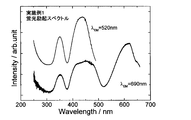
- 2 shows a fluorescence excitation spectrum in Example 1.
- the excitation spectrum was measured using a fluorescence spectrophotometer (RF5300) manufactured by Shimadzu Corporation.
- the upper spectrum is an excitation spectrum obtained by monitoring Ce 3+ emission at 520 nm
- the lower spectrum is an excitation spectrum obtained by monitoring emission of Cr 3+ at 690 nm. It can be seen that both Ce 3+ emission and Cr 3+ emission can be efficiently excited by ultraviolet and blue light.
- the fluorescence spectrum and afterglow spectrum (after 5 minutes) in Example 1 are shown.
- This spectrum was measured by using a luminance measurement system manufactured by Konica Minolta Co., Ltd., using 460 nm obtained by spectrally separating a xenon lamp light source (MAX302) manufactured by Asahi Spectroscopy Co., Ltd. with a bandpass filter. Strong emission of Ce 3+ (520 nm) and Cr 3+ (700 nm) was observed in both emission and afterglow spectra.
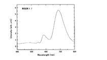
- FIG. 10 shows an afterglow spectrum by ultraviolet storage in Example 17. FIG. Almost no afterglow of Ce 3+ was observed, and only 700m strong afterglow of Mn ions was observed.
- ⁇ em 505 nm
- ⁇ ex 350 nm
- Comparative Example 1 only emission from 500 nm Ce 3+ was observed.
- the results of thermoluminescence measurements on the phosphors of Examples 1, 4, and 5 and Comparative Example 1 are shown.
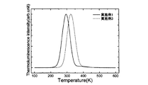
- the thermoluminescence measurement result in the fluorescent substance of Example 1 and 3 is shown.
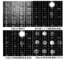
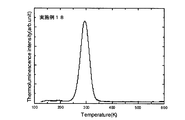
- the phosphors of Examples 6 to 16 were (a) under white LED illumination, (b) afterglow characteristics immediately after the UV lamp was shut off (room temperature), (c) afterglow characteristics immediately after the white LED illumination was shut off (room temperature), and ( d) A photograph showing the afterglow characteristics immediately after shutting off the white LED lighting (150 ° C). All the phosphors of Examples 6 to 16 exhibit afterglow after ultraviolet excitation and after blue light excitation by LED illumination. The thermoluminescence measurement result in the fluorescent substance of Example 18 is shown.
- Example 1 The following raw material powders and 30 ml of ethanol were mixed using a ball mill (product name premium line P-7, manufactured by Fritsch, manufactured by Fritsch Japan Ltd.) to obtain a mixture. Next, the mixture was calcined at 1200 ° C. for 6 hours using an electric furnace (product name KBF314N1, manufactured by Koyo Thermo System Co., Ltd.), and then further using an electric furnace (product name KBF314N1, manufactured by Koyo Thermo System Co., Ltd.). The main calcination was performed at 1600 ° C. for 24 hours. In addition, this baking was performed in the atmospheric condition.
- a ball mill product name premium line P-7, manufactured by Fritsch, manufactured by Fritsch Japan Ltd.
- the excitation spectrum of the phosphor of Example 1 was measured using a fluorescence spectrophotometer (RF5300) manufactured by Shimadzu Corporation.
- FIG. 4 shows the fluorescence excitation spectrum in Example 1.
- FIG. 4 shows that both Ce 3+ emission and Cr 3+ emission can be efficiently excited by ultraviolet and blue light.
- the fluorescence spectrum and afterglow spectrum of the phosphor of Example 1 were measured. 460 nm obtained by spectrally separating a xenon lamp light source (MAX302) manufactured by Asahi Spectroscopic Co., Ltd. with a bandpass filter was used as an excitation light source, and emission and afterglow spectra were measured using a luminance measurement system manufactured by Konica Minolta.
- FIG. 5 shows the fluorescence spectrum and afterglow spectrum (after 5 minutes) in Example 1. Strong emission of Ce 3+ (520 nm) and Cr 3+ (700 nm) was observed in both emission and afterglow spectra.
- FIG. 3 shows an X-ray diffraction pattern (using CuK ⁇ rays) in the phosphor of Example 2.
- Example 3 The following raw material powders and 30 ml of ethanol were mixed using a ball mill (product name premium line P-7, manufactured by Fritsch, manufactured by Fritsch Japan Ltd.) to obtain a mixture. Next, the mixture was calcined at 1200 ° C. for 6 hours using an electric furnace (product name KBF314N1, manufactured by Koyo Thermo Systems Co., Ltd.), and then a vacuum tubular electric furnace (product name VF-1800, manufactured by Crystal Systems Co., Ltd.). ) And then calcined at 1600 ° C. for 24 hours. The main firing was performed in a vacuum atmosphere.
- a ball mill product name premium line P-7, manufactured by Fritsch, manufactured by Fritsch Japan Ltd.
- the phosphor of Example 5 was obtained by doping Fe into a compound having a total number of moles of C and Ga (Ga) of 0.6]. The amount of Fe doped was 0.3 mol% with respect to the compound.
- each metal element M in Examples 6 to 16 was 0.1 mol% with respect to the compound.
- V 2 O 5 manufactured by Aldrich
- Example 17 The following raw material powders and 30 ml of ethanol were mixed using a ball mill (product name premium line P-7, manufactured by Fritsch, manufactured by Fritsch Japan Ltd.) to obtain a mixture. The mixture was then fired for 24 hours in a tubular electric furnace (product name VF-1800, manufactured by Crystal Systems Co., Ltd.) in an N2-H2 (5%) atmosphere.
- a ball mill product name premium line P-7, manufactured by Fritsch, manufactured by Fritsch Japan Ltd.
- FIG. 6 shows an afterglow spectrum by ultraviolet storage in Example 17. Almost no afterglow of Ce 3+ was observed, and only 700m strong afterglow of Mn ions was observed.
- Example 18 The following raw material powders and 30 ml of ethanol were mixed using a ball mill (product name premium line P-7, manufactured by Fritsch, manufactured by Fritsch Japan Ltd.) to obtain a mixture. Subsequently, the mixture was fired at 1600 ° C. for 12 hours using an electric furnace (product name KBF314N1, manufactured by Koyo Thermo System Co., Ltd.). The firing was performed in a vacuum atmosphere.
- a ball mill product name premium line P-7, manufactured by Fritsch, manufactured by Fritsch Japan Ltd.
- the phosphor has a composition of (Y 0.995 Ce 0.005 ) 3 Al 1.5 Ga 3.5 O 12 [Number of moles of Ga / (total number of moles of B (Al and Ga) and C (Ga)) is 0.7] It can also be said that the compound represented by the formula is a phosphor in which 0.15 mol% of Yb is doped.
- FIG. 3 shows an X-ray diffraction pattern (using CuK ⁇ rays) in the phosphor of Comparative Example 1.
- Reference example 1 A phosphor of SrAl 2 O 4 : Eu 2+ -Dy 3+ (GLL-300FFS, manufactured by Nemoto Special Chemical Co., Ltd.) was prepared.
- Test example 1 Thermoluminescence measurement
- the phosphors obtained in Examples 1, 3 to 5 and 18 and Comparative Example 1 were formed into pellets. Specifically, the above phosphors were compression molded at 50 MPa using a pellet molding machine (product name NT-50H, manufactured by Sansho Industry Co., Ltd.) to form pellets having a diameter of 10 mm and a thickness of 2 mm. .
- a pellet molding machine product name NT-50H, manufactured by Sansho Industry Co., Ltd.
- thermoluminescence measurement was performed on each phosphor. Specifically, each sample was irradiated with excitation light (ultraviolet light of 250 nm to 400 nm), and after the irradiation was cut off, the emission luminance was measured while raising the temperature of each sample from 100K. This measurement makes it possible to observe at which temperature each sample has the best afterglow characteristics.
- excitation light ultraviolet light of 250 nm to 400 nm
- the phosphor of Example 1 (doped M element: Cr, B in the above formula (1) is Al, C in the above formula (1) is Ga, and the moles of Ga. Number / (total number of moles of B and C) is 0.6), whereas a large peak was observed around 300K, whereas the phosphor of Example 3 (doped M element: Cr, the above formula (1)) A large peak was observed in the vicinity of 330K, with B in Al and C in the above formula (1) being Al and Ga, the number of moles of Ga / (total number of moles of B and C) being 0.5).
- the glow peak can be shifted to the high temperature side. It was revealed that the initial intensity and afterglow duration at room temperature can be set as appropriate. 9, the electron trap depth of the phosphor of Example 1 was estimated to be 0.59 eV, and the electron trap depth of the phosphor of Example 3 was estimated to be 0.65 eV.
- Test example 2 Measurement of afterglow luminance after ultraviolet light irradiation
- the phosphors obtained in Examples 1 to 3, Comparative Example 1 and Reference Example 1 were formed into pellets having a diameter of 10 mm and a thickness of 2 mm by the same method as in Test Example 1.
- excitation light (ultraviolet light 360 nm) was irradiated to each of the above-mentioned pellet-shaped phosphors, and afterglow luminance was measured 5 minutes, 20 minutes, and 1 hour after the irradiation was cut off.
- a shutter was placed in front of the detector for baseline measurement, and the shutter was closed after 120 minutes.
- Test example 3 Measurement of afterglow luminance after blue light irradiation Except for irradiating blue light (460 nm) instead of ultraviolet light (360 nm) as excitation light, the afterglow luminance of each of the above-mentioned pellet-shaped phosphors (blocking blue light irradiation was interrupted) in the same manner as in Test Example 2. The afterglow brightness after 5 minutes, 20 minutes and 1 hour was measured.
- the phosphors of Examples 1 to 3 are excellent in long afterglow characteristics due to ultraviolet light excitation and also excellent in long afterglow characteristics due to blue light excitation.
- the phosphors of Examples 1 to 3 have an extremely high afterglow luminance after one hour after blocking the excitation by blue light as compared with Reference Example 1. This is due to the generation of electron traps by co-doped ions (M) and the translucency of the sample.
- Blue light (460 nm) is an emission wavelength of a general-purpose InGaN blue LED, and is generally used for a white LED realized by a blue LED + yellow phosphor, and is therefore optimal as an excitation wavelength of blue light.
- Test Example 4 (Afterglow decay curve evaluation after blue light irradiation) The phosphors obtained in Examples 1 to 3 were pelletized by the same method as in Test Example 1. Next, each pellet-like phosphor was irradiated with excitation light (blue light 460 nm), and afterglow decay curves of each pellet-like phosphor after the irradiation was cut off were measured. From the afterglow decay curve, a time (afterglow time) when the afterglow luminance was less than 2 mcd / m 2 was obtained. ⁇ Each condition of Test Example 4> Excitation light source: Product name MAX302 Asahi Spectral Co., Ltd.
- Afterglow luminance measurement device Product name Luminance measurement system, manufactured by Konica Minolta Co., Ltd. ⁇ Excitation light irradiation time: 5 minutes ⁇ Baseline measurement: 120 minutes Rear, temperature: 25 °C As a result, the afterglow time in Example 1 was 265 minutes, the afterglow time in Example 2 was 485 minutes, and the afterglow time in Example 3 was 792 minutes, both of which have excellent long afterglow characteristics due to blue light excitation. It was shown that
- Test Example 5 Afterglow characteristics evaluation after ultraviolet light irradiation
- the phosphors obtained in Examples 6 to 16 and Comparative Example 1 were formed into pellets having a diameter of 10 mm and a thickness of 2 mm by the same method as in Test Example 1.
- excitation light (ultraviolet light 360 nm) was irradiated to each of the above-mentioned pellet-shaped phosphors, and afterglow characteristics (light storage characteristics) of each phosphor immediately after the irradiation was cut off were visually evaluated.
- the evaluation criteria are as follows. The afterglow characteristics due to ultraviolet excitation of the phosphors obtained in Examples 6 to 16 are shown in FIG. 10 below.
- Test Example 6 Evaluation of afterglow characteristics after blue light irradiation
- the afterglow characteristics (phosphorescence characteristics) of each of the above-mentioned pellet-shaped phosphors are the same as in Test Example 5, except that a white LED containing blue light (460 nm) is used instead of ultraviolet light (360 nm) as excitation light. Was visually evaluated.
- the evaluation criteria are the same as in Test Example 5.
- Test Examples 5 and 6 are shown in Table 2 below. ⁇ Each condition of Test Example 6> ⁇ Excitation light irradiation time: 5 minutes ⁇ Air temperature: Room temperature (25 °C) and 150 °C
- the phosphors of Examples 6 to 16 are excellent in long afterglow characteristics due to ultraviolet light excitation and also excellent in long afterglow characteristics due to blue light excitation.
Landscapes
- Chemical & Material Sciences (AREA)
- Inorganic Chemistry (AREA)
- Engineering & Computer Science (AREA)
- Materials Engineering (AREA)
- Organic Chemistry (AREA)
- Luminescent Compositions (AREA)
- Paints Or Removers (AREA)
- Medicines Containing Antibodies Or Antigens For Use As Internal Diagnostic Agents (AREA)
Abstract
本発明の課題は、紫外線励起による長残光特性に優れ、且つ、青色光励起による長残光特性に優れた蛍光体及びその製造方法を提供することである。本発明は、下記組成式 (1): A3B2C3O12 (1) (式中、 Aは、(i) Mg、Ca、Sr、La、Gd、Tb、Lu、及びYからなる群から選ばれた少なくとも1種の元素、並びに、(ii)Ceであり、 BはAl、Ga、Sc、In、Mg、Lu、及びYからなる群から選ばれた少なくとも1種の元素であり、 CはSi、Ge、Al及びGaからなる群から選ばれた少なくとも1種の元素である)で表される化合物に、 Ti、V、Cr、Mn、Fe、Co、Ni、Cu、Zn、Zr、Hf、Si、Yb、Eu、Pr及びTbからなる群から選ばれた少なくとも1種の金属元素がドープされていることを特徴とする蛍光体に関する。
Description
本発明は、蛍光体、及び蛍光体の製造方法に関する。
蓄光型長残光蛍光体は、外部からのエネルギー(例:紫外線、紫光等)によって生成した電子・ホール等のキャリアを一時的に結晶内欠陥にトラップ(trap)し、当該トラップされたキャリアが気温の熱エネルギーによって徐々に解放し、発光中心で再結合することにより長時間持続する発光を示すものである。この長残光蛍光体は、日中の太陽光エネルギー、室内照明の光エネルギー等を蓄えて、夜間時や消灯後に光るため、視認性夜光塗料として使用できる。そのため、当該長残光蛍光体は、安全標識や避難誘導システムに使用されている。
現在までに報告されている長残光蛍光体(例:SrAl2O4:Eu2+-Dy3+等)は、一般的に、紫外光(紫外線)や紫光等の短波長の光に対して励起効率が高い。このような長残光蛍光体を太陽光や蛍光灯の下で使用する場合、当該太陽光や蛍光灯からの光には紫外線等が含まれているので、上記長残光蛍光体を問題なく使用することができる。
しかしながら、近年、上記蛍光灯に代わって、長期安定性、省エネルギー、高い発光量子効率等の特徴を有する白色LED(Light Emitting Diode)が固体照明デバイスとして多く使用されてきている。一般的に普及している白色LEDは、青色LEDと黄色蛍光体との組み合わせ、又は青色LEDと赤色蛍光体と緑色蛍光体との組み合わせで構成されている。つまり、上記白色LEDからの光には最も短い波長の光として青色光が含まれているだけであり、紫外線が含まれていない。そのため、近年の室内照明が白色LEDに移行されていくことに起因して、長残光蛍光体に求められる特性として蛍光灯からの蓄光だけでなく白色LEDからの光から蓄光も可能かどうか(言い換えれば、紫外線等による蓄光だけでなく、青色光による蓄光も可能かどうか)が求められている。
青色領域での光を吸収する蛍光体としては、Ce3+添加A3B2C3O12ガーネット蛍光体(例えば、Ce3+:Y3Al2Al3O12、以後Ce3+:YAG蛍光体ともいう)が知られている。当該Ce3+:YAG蛍光体は、青色領域での光を吸収し、高い量子効率を有する黄色発光を示すため、白色LEDを構成する蛍光体(即ち、青色LEDと組み合わせて使用する上記黄色蛍光体)として実用化されている。しかしながら、Ce3+:YAGは、青色光励起による残光特性を示さない。
また、青色領域での光を吸収する別の組成のCe3+添加ガーネット蛍光体として、Ce3+添加Y3Al5-xGaxO12(以下、Ce3+:YAGGともいう)(x=3、3.5)が知られている(非特許文献1)。この非特許文献1には、Ce3+:YAGG(x=3、3.5)が、紫外光励起において残光を示すという記述がある。
J. W. W. Holloway, and M. Kestigian, "Optical Properties of Cerium-Activated Garnet Crystals," J. Opt. Soc. Am. 59, 60-63 (1969).
しかしながら、当該Ce3+:YAGGの青色光励起による長残光特性については報告がほとんどない。
そこで、本発明者らは、上記Ce3+:YAGGの青色光励起による長残光特性について検討した。その結果、Ce3+:YAGGは、青色光で励起した後に当該青色光を遮断すると残光特性を示すものの、その残光強度(残光輝度)が非常に低いことを突き止めた。
従って、本発明は、紫外線励起による長残光特性に優れ、且つ、青色光励起による長残光特性に優れた蛍光体及びその製造方法の提供を目的とする。
本発明者らは、鋭意研究を重ねた結果、特定の組成で表される蛍光体によれば、上記目的を達成できることを見出し、本発明を完成するに至った。
即ち、本発明は、下記の蛍光体(ガーネット結晶蛍光体)及びその製造方法に関する。1. 下記組成式 (1):
A3B2C3O12 (1)
(式中、
Aは、(i) Mg、Ca、Sr、La、Gd、Tb、Lu、及びYからなる群から選ばれた少なくとも1種の元素、並びに、(ii)Ceであり、
BはAl、Ga、Sc、In、Mg、Lu、及びYからなる群から選ばれた少なくとも1種の元素であり、
CはSi、Ge、Al及びGaからなる群から選ばれた少なくとも1種の元素である)で表される化合物に、
Ti、V、Cr、Mn、Fe、Co、Ni、Cu、Zn、Zr、Hf、Si、Yb、Eu、Pr及びTbからなる群から選ばれた少なくとも1種の金属元素がドープされていることを特徴とする蛍光体。
2. 前記金属元素のドープ量が、前記式(1)で表される化合物に対して0.001~5モル%である、上記項1に記載の蛍光体。
3. 前記(i)の元素と前記(ii)Ceとのモル比が、0.9999:0.0001~0.95:0.05である、上記項1又は2に記載の蛍光体。
4. 蓄光蛍光体、白色LED、蓄光セラミックス、蓄光樹脂、蓄光塗料、蓄光式避難誘導システム、又はバイオイメージング用マーカーに用いられる、上記項1~3のいずれかに記載の蛍光体。
5. 下記組成式 (1):
A3B2C3O12 (1)
(式中、
Aは、(i) Mg、Ca、Sr、La、Gd、Tb、Lu、及びYからなる群から選ばれた少なくとも1種の元素、並びに、(ii)Ceであり、
BはAl、Ga、Sc、In、Mg、Lu、及びYからなる群から選ばれた少なくとも1種の元素であり、
CはSi、Ge、Al及びGaからなる群から選ばれた少なくとも1種の元素である)で表される化合物に、
Ti、V、Cr、Mn、Fe、Co、Ni、Cu、Zn、Zr、Hf、Si、Yb、Eu、Pr及びTbからなる群から選ばれた少なくとも1種の金属元素がドープされている蛍光体の製造方法であって、
(1) 前記(i)の元素含有化合物、B元素含有化合物、C元素含有化合物、Ce含有化合物及び前記金属元素含有化合物を含む組成物を用意する工程1、及び
(2) 前記組成物を1200~1800℃で加熱する工程2
を順に含む、蛍光体の製造方法。
A3B2C3O12 (1)
(式中、
Aは、(i) Mg、Ca、Sr、La、Gd、Tb、Lu、及びYからなる群から選ばれた少なくとも1種の元素、並びに、(ii)Ceであり、
BはAl、Ga、Sc、In、Mg、Lu、及びYからなる群から選ばれた少なくとも1種の元素であり、
CはSi、Ge、Al及びGaからなる群から選ばれた少なくとも1種の元素である)で表される化合物に、
Ti、V、Cr、Mn、Fe、Co、Ni、Cu、Zn、Zr、Hf、Si、Yb、Eu、Pr及びTbからなる群から選ばれた少なくとも1種の金属元素がドープされていることを特徴とする蛍光体。
2. 前記金属元素のドープ量が、前記式(1)で表される化合物に対して0.001~5モル%である、上記項1に記載の蛍光体。
3. 前記(i)の元素と前記(ii)Ceとのモル比が、0.9999:0.0001~0.95:0.05である、上記項1又は2に記載の蛍光体。
4. 蓄光蛍光体、白色LED、蓄光セラミックス、蓄光樹脂、蓄光塗料、蓄光式避難誘導システム、又はバイオイメージング用マーカーに用いられる、上記項1~3のいずれかに記載の蛍光体。
5. 下記組成式 (1):
A3B2C3O12 (1)
(式中、
Aは、(i) Mg、Ca、Sr、La、Gd、Tb、Lu、及びYからなる群から選ばれた少なくとも1種の元素、並びに、(ii)Ceであり、
BはAl、Ga、Sc、In、Mg、Lu、及びYからなる群から選ばれた少なくとも1種の元素であり、
CはSi、Ge、Al及びGaからなる群から選ばれた少なくとも1種の元素である)で表される化合物に、
Ti、V、Cr、Mn、Fe、Co、Ni、Cu、Zn、Zr、Hf、Si、Yb、Eu、Pr及びTbからなる群から選ばれた少なくとも1種の金属元素がドープされている蛍光体の製造方法であって、
(1) 前記(i)の元素含有化合物、B元素含有化合物、C元素含有化合物、Ce含有化合物及び前記金属元素含有化合物を含む組成物を用意する工程1、及び
(2) 前記組成物を1200~1800℃で加熱する工程2
を順に含む、蛍光体の製造方法。
用語の説明
本明細書において、「長残光」とは、励起光(例:紫外線、紫光、青色光等)を照射した後に当該励起光を遮断(停止)しても長時間(例:数分~数十時間以上)発光し続けることをいい、原子の電子遷移が示す発光の時間スケール(ns~ms)と明確に区別できる。本明細書において、当該長残光機能を有する蛍光体を「長残光蛍光体」ともいい、本発明の蛍光体は長残光蛍光体である。なお、本発明における残光の中心波長(発光ピーク)は480~700nm程度(緑~赤)である。
本明細書において、「長残光」とは、励起光(例:紫外線、紫光、青色光等)を照射した後に当該励起光を遮断(停止)しても長時間(例:数分~数十時間以上)発光し続けることをいい、原子の電子遷移が示す発光の時間スケール(ns~ms)と明確に区別できる。本明細書において、当該長残光機能を有する蛍光体を「長残光蛍光体」ともいい、本発明の蛍光体は長残光蛍光体である。なお、本発明における残光の中心波長(発光ピーク)は480~700nm程度(緑~赤)である。
本明細書において、「蓄光」とは、光を蓄える(溜める)ように電子・ホール等のキャリアを蓄える(溜める、又はトラップ(trap)する)ことを意味する。ここで、上記キャリアは、紫外線や紫光、青色光等の外部からのエネルギーによって生成しトラップに捕獲され、外気の熱エネルギーによって解放することにより発光する。
本明細書において、「青色光」とは、特に説明がない限り、波長400~460nmの可視光をいう。
本明細書において、「紫外線(紫外光)」とは、特に説明がない限り、波長200~380nmの紫外線をいう。
本明細書において、「室温」とは、特に説明がない限り、気温が10~30℃であることをいう。
≪1.本発明の蛍光体≫
本発明の蛍光体は、下記組成式 (1):
A3B2C3O12 (1)
(式中、
Aは、(i) Mg、Ca、Sr、La、Gd、Tb、Lu、及びYからなる群から選ばれた少なくとも1種の元素、並びに、(ii)Ceであり、
BはAl、Ga、Sc、In、Mg、Lu、及びYからなる群から選ばれた少なくとも1種の元素であり、
CはSi、Ge、Al及びGaからなる群から選ばれた少なくとも1種の元素である)で表される化合物に、
Ti、V、Cr、Mn、Fe、Co、Ni、Cu、Zn、Zr、Hf、Si、Yb、Eu、Pr及びTbからなる群から選ばれた少なくとも1種の金属元素がドープされていることを特徴とする。
本発明の蛍光体は、下記組成式 (1):
A3B2C3O12 (1)
(式中、
Aは、(i) Mg、Ca、Sr、La、Gd、Tb、Lu、及びYからなる群から選ばれた少なくとも1種の元素、並びに、(ii)Ceであり、
BはAl、Ga、Sc、In、Mg、Lu、及びYからなる群から選ばれた少なくとも1種の元素であり、
CはSi、Ge、Al及びGaからなる群から選ばれた少なくとも1種の元素である)で表される化合物に、
Ti、V、Cr、Mn、Fe、Co、Ni、Cu、Zn、Zr、Hf、Si、Yb、Eu、Pr及びTbからなる群から選ばれた少なくとも1種の金属元素がドープされていることを特徴とする。
上記特徴を有する本発明の蛍光体は、特に、Ce元素を含む特定のガーネット結晶蛍光体に特定の金属元素(当該特定の金属元素をM元素ともいう。)をドープすることにより、紫外線励起による長残光特性に優れ、且つ、青色光励起による長残光特性に優れる。また、本発明の蛍光体は、耐水性にも優れる。
本発明の蛍光体は、Ce及び特定金属元素共添加ガーネット結晶蛍光体ともいう。ここで、ガーネット結晶構造及び占有カチオンの模式図を図1に示す。一般的なガーネット結晶構造(ガーネット型構造)の組成は、前記組成式(1):A3B2C3O12で表される。上記式(1)中のAで示される元素(A元素)のカチオンは12面体サイトを占有し、上記式(1)中のBで示される元素(B元素)のカチオンは8面体サイトを占有し、上記式(1)中のCで示される元素(C元素)のカチオンは4面体サイトを占有する。本発明の蛍光体は、母体結晶である上記ガーネット結晶において、Ce及びM元素を共添加して得られた蛍光体である。ここで、上記式(1)中のAの(ii)Ceは発光中心となるCe3+を含むことを意味するものであり、当該Ce3+は12面体サイトを占有する。また、上記M元素のカチオンは主に、8面体サイトを占有する場合が多い。
本発明の蛍光体におけるガーネット型構造は、固溶体領域を有する場合がある。この場合、結晶内で格子欠陥やアンチサイト欠陥が生じ、上記式(1)に対して若干の組成比のズレが生じることがある(即ち、本発明の蛍光体は、上記式(1)に対して不定比(非化学)量論組成を有する場合がある)が、上記不定比量論組成を有する場合も本発明の範囲内である。
本発明の蛍光体の結晶構造は、X線回折法等によって確認することができる。
A元素
Aは、(i)Mg、Ca、Sr、La、Gd、Tb、Lu及びYからなる群から選ばれた少なくとも1種の元素、並びに、(ii)Ceである。Aのカチオン(上記(i)の元素のカチオン及び(ii)Ceのカチオン)は8配位位置にあり、12面体サイトを占有する(当該サイトをAサイトともいう)。
Aは、(i)Mg、Ca、Sr、La、Gd、Tb、Lu及びYからなる群から選ばれた少なくとも1種の元素、並びに、(ii)Ceである。Aのカチオン(上記(i)の元素のカチオン及び(ii)Ceのカチオン)は8配位位置にあり、12面体サイトを占有する(当該サイトをAサイトともいう)。
<(i)で表される元素>
Aの内の上記(i)で表される元素(Mg、Ca、Sr、La、Gd、Tb、Lu及びYからなる群から選ばれた少なくとも1種)は、1種又は2種以上の元素を使用することができる。なお、(i)で表される元素として、Mg、Ca及びSrからなる群から選ばれた少なくとも1種の元素(当該元素のカチオンは2価のカチオン)を使用する場合は、電気的中性の観点から、Cとして4価のカチオンとなる元素を使用する必要がある。
Aの内の上記(i)で表される元素(Mg、Ca、Sr、La、Gd、Tb、Lu及びYからなる群から選ばれた少なくとも1種)は、1種又は2種以上の元素を使用することができる。なお、(i)で表される元素として、Mg、Ca及びSrからなる群から選ばれた少なくとも1種の元素(当該元素のカチオンは2価のカチオン)を使用する場合は、電気的中性の観点から、Cとして4価のカチオンとなる元素を使用する必要がある。
上記(i)の元素の中でも、Lu、Gd及びYからなる群から選ばれた少なくとも1種の元素が好ましく、Yがより好ましい。
<(ii)Ce元素>
CeのカチオンCe3+は発光中心であって、Aサイト(12面体サイト)を占有する。
CeのカチオンCe3+は発光中心であって、Aサイト(12面体サイト)を占有する。
Ce3+は4f-5d許容遷移による強くブロードな吸収と高い発光効率をもつ。また、Ce3+の5d準位は、電子雲膨張効果によるセントロイドシフトにより低エネルギー化し、結晶場の影響によりホスト構造中で複数の準位に分裂する。ここで、ガーネット結晶構造の組成によるバンド構造変化を図2に示す。本発明の蛍光体は、ガーネット結晶構造をホストとするため、Ce3+の5d軌道は5本に分裂し、その分裂幅はガーネット結晶組成に依存する。よって、上述の通り、ガーネット結晶組成を変化させることでCe3+の光学特性(発光色)を変化させることが可能である。
上記Aの内、(i)の元素と(ii)Ce元素との割合(モル比)は、(i)の元素:(ii)Ce元素=0.9999:0.0001~0.95:0.05(99.99:0.01~95:5(モル比(%)))であることが好ましく、0.9995:0.0005~0.99:0.01(99.95:0.05~99:1(モル比(%)))であることがより好ましい。(i)の元素と(ii)Ce元素とのモル比が上記範囲内であることにより、濃度が薄くなることによる励起光の吸収強度の低下や濃度が濃くなることによって起こる濃度消光の欠点が生じることなく、紫外線励起及び青色光励起による長残光特性にさらに優れる。なお、Ce3+を起源とする残光の中心波長はガーネット結晶組成により異なり、主に500nm~550nmの範囲内に存在する。
B元素
Bは、Al、Ga、Sc、In、Mg、Lu及びYからなる群から選ばれた少なくとも1種の元素である。Bのカチオンは6配位8面体サイトを占有する(当該サイトをBサイトともいう)。Bは、1種又は2種以上の元素を使用することができる。
Bは、Al、Ga、Sc、In、Mg、Lu及びYからなる群から選ばれた少なくとも1種の元素である。Bのカチオンは6配位8面体サイトを占有する(当該サイトをBサイトともいう)。Bは、1種又は2種以上の元素を使用することができる。
Bの中でも、Al及びGaからなる群から選ばれた少なくとも1種の元素が好ましい。
C元素
Cは、Si、Ge、Al及びGaからなる群から選ばれた少なくとも1種の元素である。Cのカチオンは4配位位置にあり、4面体サイトを占有する(当該サイトをCサイトともいう)。Cは、1種又は2種以上の元素を使用することができる。なお、CとしてSi及びGeからなる群から選ばれた少なくとも1種の元素(当該元素のカチオンは4価のカチオン)を使用する場合は、電気的中性の観点から、Aの(i)で表される元素として2価のカチオンとなる元素を使用する必要がある。
Cは、Si、Ge、Al及びGaからなる群から選ばれた少なくとも1種の元素である。Cのカチオンは4配位位置にあり、4面体サイトを占有する(当該サイトをCサイトともいう)。Cは、1種又は2種以上の元素を使用することができる。なお、CとしてSi及びGeからなる群から選ばれた少なくとも1種の元素(当該元素のカチオンは4価のカチオン)を使用する場合は、電気的中性の観点から、Aの(i)で表される元素として2価のカチオンとなる元素を使用する必要がある。
Cの中でも、Al及びGaからなる群から選ばれた少なくとも1種の元素が好ましく、Gaがより好ましい。
ここで、B及びCのいずれもAl及びGaからなる群から選ばれた少なくとも1種の元素である場合(即ち、本発明の蛍光体が、下記組成式(2):
A3(Al,Ga)2(Al,Ga)3O12 (2)
[前記Aは上記に同じ。]
で表される化合物に、前記M元素がドープされている蛍光体である場合)における、Gaのモル数/(BとCの合計モル数)と青色光励起による残光特性との関係について説明する。本発明の蛍光体に励起光を照射すると、発光中心となるCe3+が持つ電子が励起準位に励起されて、当該励起された電子が当該励起準位よりも低い準位に戻る。この当該励起された電子が上記準位に戻る時にエネルギーを光として放出する現象が、発光である。一方、Ce3+が持つ電子が電子トラップ(electron trap:一時的に電子を溜めることができるところ)に捕捉された後、当該電子が気温の熱エネルギーを受けることによって電子トラップから飛び出して元のCe3+に戻ってきたときに発光する現象が、残光である。よって、Ce3+が持つ電子を効率良く電子トラップに輸送することが長時間の残光特性に繋がる。
A3(Al,Ga)2(Al,Ga)3O12 (2)
[前記Aは上記に同じ。]
で表される化合物に、前記M元素がドープされている蛍光体である場合)における、Gaのモル数/(BとCの合計モル数)と青色光励起による残光特性との関係について説明する。本発明の蛍光体に励起光を照射すると、発光中心となるCe3+が持つ電子が励起準位に励起されて、当該励起された電子が当該励起準位よりも低い準位に戻る。この当該励起された電子が上記準位に戻る時にエネルギーを光として放出する現象が、発光である。一方、Ce3+が持つ電子が電子トラップ(electron trap:一時的に電子を溜めることができるところ)に捕捉された後、当該電子が気温の熱エネルギーを受けることによって電子トラップから飛び出して元のCe3+に戻ってきたときに発光する現象が、残光である。よって、Ce3+が持つ電子を効率良く電子トラップに輸送することが長時間の残光特性に繋がる。
そこで、(a)B及びC中のGaの組成比(存在比)を大きくすると、Ce3+の励起5d準位とガーネット母体結晶の伝導帯とのエネルギー差が小さくなるので、より効率的に上記電子を電子トラップに輸送することが可能となる。一方、(b)Gaの組成比を小さくすると、電子トラップと伝導帯とのエネルギー差が大きくなることになり、最も残光特性を強く示す温度が高温側にシフトする。従って、上記(a)及び(b)を考慮して、本発明の蛍光体におけるGa組成比は、Gaのモル数/(BとCの合計モル数)が0.5~0.8となるように設定することが好ましい。なお、上記Gaのモル数/(BとCの合計モル数)が0.6である場合、Bサイト(8面体サイト)をAlが占有し、Cサイト(4面体サイト)をGaが占有する。上記Gaのモル数/(BとCの合計モル数)が0.6未満である場合、BサイトをAlが占有し、CサイトをGaとAlが占有する。上記Gaのモル数/(BとCの合計モル数)が0.6を超える場合、BサイトをGaとAlが占有し、CサイトをGaが占有する。
金属元素M
本願発明の蛍光体は、Ti、V、Cr、Mn、Fe、Co、Ni、Cu、Zn、Zr、Hf、Si、Yb、Eu、Pr及びTbからなる群から選ばれた少なくとも1種の金属元素がドープされている。当該金属元素Mは、共添加イオンとして、上述の電子トラップを新たに形成する。当該M元素は、1種又は2種以上の上記金属元素を使用することができる。
本願発明の蛍光体は、Ti、V、Cr、Mn、Fe、Co、Ni、Cu、Zn、Zr、Hf、Si、Yb、Eu、Pr及びTbからなる群から選ばれた少なくとも1種の金属元素がドープされている。当該金属元素Mは、共添加イオンとして、上述の電子トラップを新たに形成する。当該M元素は、1種又は2種以上の上記金属元素を使用することができる。
M元素の中でも、Cr、Ni、Fe、V、Yb及びSiからなる群から選ばれた少なくとも1種が好ましく、Cr、Ni、Yb及びSiからなる群から選ばれた少なくとも1種がより好ましく、Cr及びYbからなる群から選ばれた少なくとも1種がさらに好ましく、Crが特に好ましい。
M元素のドープ量は、上記式(1)で表される化合物に対して0.001~5モル%であることが好ましく、0.01~1モル%がより好ましく、0.05~0.5モル%がさらに好ましい。M元素のドープ量が上記範囲内であることにより、残光強度の低下が生じることなく、紫外線励起及び青色光励起による長残光特性にさらに優れる。
ここで、本発明の蛍光体の好ましい態様の例を述べる。本発明の蛍光体を室温下で使用する場合、
組成式(1):A3B2C3O12 (1)
[式中、AがY及びCe(YとCeとのモル比がY:Ce=0.9999:0.0001~0.95:0.05)、BがAl及びGaからなる群から選ばれた少なくとも1種の元素、CがAl及びGaからなる群から選ばれた少なくとも1種の元素、Gaのモル数/(BとCの合計モル数)が0.5~0.8である]
で表される化合物に、前記化合物に対して0.001~5モル%のCrがドープされている蛍光体(Cr共ドープ蛍光体ともいう)が好ましい。このCr共ドープ蛍光体における残光の中心波長は、該蛍光体のガーネット結晶組成から、Ce3+を起源とする残光の中心波長に相当する510nmであり、人間の目に見えやすい。また、700nm付近においてもCr3+が残光するため、バイオイメージング用の残光蛍光体としても有用である。
組成式(1):A3B2C3O12 (1)
[式中、AがY及びCe(YとCeとのモル比がY:Ce=0.9999:0.0001~0.95:0.05)、BがAl及びGaからなる群から選ばれた少なくとも1種の元素、CがAl及びGaからなる群から選ばれた少なくとも1種の元素、Gaのモル数/(BとCの合計モル数)が0.5~0.8である]
で表される化合物に、前記化合物に対して0.001~5モル%のCrがドープされている蛍光体(Cr共ドープ蛍光体ともいう)が好ましい。このCr共ドープ蛍光体における残光の中心波長は、該蛍光体のガーネット結晶組成から、Ce3+を起源とする残光の中心波長に相当する510nmであり、人間の目に見えやすい。また、700nm付近においてもCr3+が残光するため、バイオイメージング用の残光蛍光体としても有用である。
また、本発明の蛍光体を高温下(例:50~80℃)で使用する場合は、
組成式(1):A3B2C3O12 (1)
[式中、AがY及びCe(YとCeとのモル比がY:Ce=0.9999:0.0001~0.95:0.05)、BがAl及びGaからなる群から選ばれた少なくとも1種の元素、CがAl及びGaからなる群から選ばれた少なくとも1種の元素、Gaのモル数/(BとCの合計モル数)が0.5~0.8である]
で表される化合物に、前記化合物に対して0.001~5モル%のNiがドープされている蛍光体(Ni共ドープ蛍光体ともいう)が好ましい。このNi共ドープ蛍光体における残光の中心波長も、該蛍光体のガーネット結晶組成から、Ce3+を起源とする残光の中心波長に相当する510nmであり、人間の目に見えやすい。
組成式(1):A3B2C3O12 (1)
[式中、AがY及びCe(YとCeとのモル比がY:Ce=0.9999:0.0001~0.95:0.05)、BがAl及びGaからなる群から選ばれた少なくとも1種の元素、CがAl及びGaからなる群から選ばれた少なくとも1種の元素、Gaのモル数/(BとCの合計モル数)が0.5~0.8である]
で表される化合物に、前記化合物に対して0.001~5モル%のNiがドープされている蛍光体(Ni共ドープ蛍光体ともいう)が好ましい。このNi共ドープ蛍光体における残光の中心波長も、該蛍光体のガーネット結晶組成から、Ce3+を起源とする残光の中心波長に相当する510nmであり、人間の目に見えやすい。
また、本発明の蛍光体を低温下(例:-60~-30℃)で使用する場合は、
組成式(1):A3B2C3O12 (1)
[式中、AがY及びCe(YとCeとのモル比がY:Ce=0.9999:0.0001~0.95:0.05)、BがAl及びGaからなる群から選ばれた少なくとも1種の元素、CがAl及びGaからなる群から選ばれた少なくとも1種の元素、Gaのモル数/(BとCの合計モル数)が0.5~0.8である]
で表される化合物に、前記化合物に対して0.001~5モル%のFeがドープされている蛍光体(Fe共ドープ蛍光体ともいう)が好ましい。このFe共ドープ蛍光体における残光の中心波長も、該蛍光体のガーネット結晶組成から、Ce3+を起源とする残光の中心波長に相当する510nmであり、人間の目に見えやすい。
組成式(1):A3B2C3O12 (1)
[式中、AがY及びCe(YとCeとのモル比がY:Ce=0.9999:0.0001~0.95:0.05)、BがAl及びGaからなる群から選ばれた少なくとも1種の元素、CがAl及びGaからなる群から選ばれた少なくとも1種の元素、Gaのモル数/(BとCの合計モル数)が0.5~0.8である]
で表される化合物に、前記化合物に対して0.001~5モル%のFeがドープされている蛍光体(Fe共ドープ蛍光体ともいう)が好ましい。このFe共ドープ蛍光体における残光の中心波長も、該蛍光体のガーネット結晶組成から、Ce3+を起源とする残光の中心波長に相当する510nmであり、人間の目に見えやすい。
また、本発明において、
組成式(1):A3B2C3O12 (1)
[式中、AがY及びCe(YとCeとのモル比がY:Ce=0.9999:0.0001~0.95:0.05)、BがAl及びGaからなる群から選ばれた少なくとも1種の元素、CがAl及びGaからなる群から選ばれた少なくとも1種の元素、Gaのモル数/(BとCの合計モル数)が0.5~0.8である]
で表される化合物に、前記化合物に対して0.001~5モル%のMnがドープされている蛍光体(Mn共ドープ蛍光体ともいう)が好ましい。このMn共ドープ蛍光体は、700nmにMnイオンを起源とした残光の中心波長を有するので、後述するバイオイメージングへの適用に有効である。
組成式(1):A3B2C3O12 (1)
[式中、AがY及びCe(YとCeとのモル比がY:Ce=0.9999:0.0001~0.95:0.05)、BがAl及びGaからなる群から選ばれた少なくとも1種の元素、CがAl及びGaからなる群から選ばれた少なくとも1種の元素、Gaのモル数/(BとCの合計モル数)が0.5~0.8である]
で表される化合物に、前記化合物に対して0.001~5モル%のMnがドープされている蛍光体(Mn共ドープ蛍光体ともいう)が好ましい。このMn共ドープ蛍光体は、700nmにMnイオンを起源とした残光の中心波長を有するので、後述するバイオイメージングへの適用に有効である。
材料形態
本発明の蛍光体の状態、形状、大きさ等は特に限定されず、使用目的に応じて適宜設定すればよい。例えば、状態としては、単結晶、多結晶(透光性セラミックス)等が、形状としては、粉末、ペレット等が挙げられる。
本発明の蛍光体の状態、形状、大きさ等は特に限定されず、使用目的に応じて適宜設定すればよい。例えば、状態としては、単結晶、多結晶(透光性セラミックス)等が、形状としては、粉末、ペレット等が挙げられる。
本発明の蛍光体が粉末である場合、当該粉末の平均粒径は0.5~50μm程度が好ましい。平均粒径の測定方法としては、公知の方法を採用すればよく、例えば光散乱法を用いた装置による測定方法が挙げられる。
本発明の蛍光体の結晶構造は、上述の通り、単結晶、多結晶のいずれであってもよい。
≪2.本発明の蛍光体の製造方法≫
本発明の蛍光体の製造方法は、特に限定されない。例えば、
下記組成式 (1):
A3B2C3O12 (1)
(式中、
Aは、(i) Mg、Ca、Sr、La、Gd、Tb、Lu、及びYからなる群から選ばれた少なくとも1種の元素、並びに、(ii)Ceであり、
BはAl、Ga、Sc、In、Mg、Lu、及びYからなる群から選ばれた少なくとも1種の元素であり、
CはSi、Ge、Al及びGaからなる群から選ばれた少なくとも1種の元素である)で表される化合物に、
Ti、V、Cr、Mn、Fe、Co、Ni、Cu、Zn、Zr、Hf、Si、Yb、Eu、Pr及びTbからなる群から選ばれた少なくとも1種の金属元素がドープされている蛍光体の製造方法であって、
(1) 前記(i)の元素含有化合物、B元素含有化合物、C元素含有化合物、Ce含有化合物及び前記金属元素含有化合物を含む組成物を用意する工程1、及び
(2) 前記組成物を1200~1800℃で加熱する工程2
を順に含む製造方法、
が挙げられる。
本発明の蛍光体の製造方法は、特に限定されない。例えば、
下記組成式 (1):
A3B2C3O12 (1)
(式中、
Aは、(i) Mg、Ca、Sr、La、Gd、Tb、Lu、及びYからなる群から選ばれた少なくとも1種の元素、並びに、(ii)Ceであり、
BはAl、Ga、Sc、In、Mg、Lu、及びYからなる群から選ばれた少なくとも1種の元素であり、
CはSi、Ge、Al及びGaからなる群から選ばれた少なくとも1種の元素である)で表される化合物に、
Ti、V、Cr、Mn、Fe、Co、Ni、Cu、Zn、Zr、Hf、Si、Yb、Eu、Pr及びTbからなる群から選ばれた少なくとも1種の金属元素がドープされている蛍光体の製造方法であって、
(1) 前記(i)の元素含有化合物、B元素含有化合物、C元素含有化合物、Ce含有化合物及び前記金属元素含有化合物を含む組成物を用意する工程1、及び
(2) 前記組成物を1200~1800℃で加熱する工程2
を順に含む製造方法、
が挙げられる。
以下、上記製造方法の各工程について詳細に説明する。
工程1
工程1では、本発明の蛍光体の原料として、前記(i)の元素含有化合物、B元素含有化合物、C元素含有化合物、Ce含有化合物及び前記金属元素(M元素)含有化合物を含む組成物(化合物含有組成物)を用意する。化合物としては、酸化物、水酸化物、ハロゲン化物(塩化物、フッ化物等)、硝酸塩、シュウ酸塩、炭酸塩、硫酸塩などがある。当該組成物中のM元素含有化合物以外の各化合物の使用量は、最終的に得られる蛍光体の組成が上記組成式(1)を満たすように、適宜決定すればよい。M元素含有化合物の使用量は、使用用途等に応じて適宜決定すればよい(なお、M元素含有化合物の使用量は、当該M元素のドープ量が上記式(1)で表される化合物に対して0.001~5モル%となるように使用することが好ましく、0.01~1モル%がより好ましく、0.05~0.5モル%がさらに好ましい)。
工程1では、本発明の蛍光体の原料として、前記(i)の元素含有化合物、B元素含有化合物、C元素含有化合物、Ce含有化合物及び前記金属元素(M元素)含有化合物を含む組成物(化合物含有組成物)を用意する。化合物としては、酸化物、水酸化物、ハロゲン化物(塩化物、フッ化物等)、硝酸塩、シュウ酸塩、炭酸塩、硫酸塩などがある。当該組成物中のM元素含有化合物以外の各化合物の使用量は、最終的に得られる蛍光体の組成が上記組成式(1)を満たすように、適宜決定すればよい。M元素含有化合物の使用量は、使用用途等に応じて適宜決定すればよい(なお、M元素含有化合物の使用量は、当該M元素のドープ量が上記式(1)で表される化合物に対して0.001~5モル%となるように使用することが好ましく、0.01~1モル%がより好ましく、0.05~0.5モル%がさらに好ましい)。
具体的には、上記A3B2C3O12 (1)で示される化合物にM元素がドープされた本発明のガーネット型構造の蛍光体を得るために、上記式(1)で示される化学量論組成となるように(上記式(1)で示される化学量論組成に従って)、(i)の元素含有化合物、B元素含有化合物、C元素含有化合物及びCe含有化合物の使用量を決定し、さらにM元素含有化合物の使用量を決定する。当該各化合物を含む組成物を用意した後、次の工程2で前記組成物を加熱(焼成)することで、本発明の蛍光体が得られる。なお、当該得られた本発明の蛍光体におけるガーネット型構造は、固溶体領域を有する場合がある。この場合、結晶内で格子欠陥やアンチサイト欠陥が生じ、上記式(1)に対して若干の組成比のズレが生じることがある(即ち、本発明の蛍光体は、上記式(1)に対して不定比量論組成を有する場合がある)が、上記不定比量論組成を有する場合も本発明の範囲内である。
前記(i)の元素含有化合物としては、(i)の元素を含有する酸化物、水酸化物、ハロゲン化物、硝酸塩、シュウ酸塩、炭酸塩、硫酸塩等が挙げられる。前記(i)の元素含有化合物は、1種で又は2種以上を組み合わせて使用することができる。
前記(i)の元素を含有する酸化物としては、MgO、CaO、SrO、La2O3、Gd2O3、Tb4O7、Lu2O3、Y2O3等が挙げられ、これらの水和物も使用することができる。
前記(i)の元素を含有する水酸化物としては、Mg(OH)2、Ca(OH)2、Sr(OH)2、La(OH)3、Gd(OH)3、Tb(OH)3、Lu(OH)3、Y(OH)3等が挙げられ、これらの水和物も使用することができる。
前記(i)の元素を含有するハロゲン化物のうち、塩化物としては、MgCl2、CaCl2、SrCl2、LaCl3、GdCl3、TbCl3、LuCl3、YCl3等が挙げられ、これらの水和物も使用することができる。
前記(i)の元素を含有する硝酸塩としては、Mg(NO3)2、Ca(NO3)2、Sr(NO3)2、La(NO3)3、Gd(NO3)3、Tb(NO3)3、Lu(NO3)3、Y(NO3)3等が挙げられ、これらの水和物も使用することができる。
前記(i)の元素を含有するシュウ酸塩としては、MgC2O4、CaC2O4、SrC2O4、La2(C2O4)3、Gd2(C2O4)3、Tb2(C2O4)3、Lu2(C2O4)3、Y2(C2O4)3等が挙げられ、これらの水和物も使用することができる。
前記(i)の元素を含有する炭酸塩としては、MgCO3、CaCO3、SrCO3、La2(CO3)3、Gd2(CO3)3、Tb2(CO3)3、Lu2(CO3)3、Y2(CO3)3等が挙げられ、これらの水和物も使用することができる。また、当該炭酸塩としては、Ca(HCO3)2等のような炭酸水素塩も包含する。
前記(i)の元素を含有する硫酸塩としては、MgSO4、CaSO4、SrSO4、La2(SO4)3、Gd2(SO4)3、Tb2(SO4)3、Lu2(SO4)3、Y2(SO4)3等が挙げられ、これらの水和物も使用することができる。
B元素含有化合物としては、B元素を含有する酸化物、水酸化物、ハロゲン化物、硝酸塩、シュウ酸塩、炭酸塩、硫酸塩等が挙げられる。前記B元素含有化合物は、1種で又は2種以上を組み合わせて使用することができる。
B元素を含有する酸化物としては、Al2O3、Ga2O3、Sc2O3、In2O3、MgO、Lu2O3、Y2O3等が挙げられ、これらの水和物も使用することができる。
B元素を含有する水酸化物としては、Al(OH)3、Ga(OH)3、Sc(OH)3、In(OH)3、Mg(OH)2、Lu(OH)3、Y(OH)3等が挙げられ、これらの水和物も使用することができる。
B元素を含有するハロゲン化物のうち、塩化物としては、AlCl3、GaCl3、ScCl3、InCl3、MgCl2、LuCl3、YCl3等が挙げられ、これらの水和物も使用することができる。
B元素を含有する硝酸塩としては、Al(NO3)3、Ga(NO3)3、Sc(NO3)3、In(NO3)3、Mg(NO3)2、Lu(NO3)3、Y(NO3)3等が挙げられ、これらの水和物も使用することができる。
B元素を含有するシュウ酸塩としては、Al2(C2O4)3、Ga2(C2O4)3、Sc2(C2O4)3、In2(C2O4)3、MgC2O4、Lu2(C2O4)3、Y2(C2O4)3等が挙げられ、これらの水和物も使用することができる。
B元素を含有する炭酸塩としては、Al2(CO3)3、Ga2(CO3)3、Sc2(CO3)3、In2(CO3)3、MgCO3、Lu2(CO3)3、Y2(CO3)3等が挙げられ、これらの水和物も使用することができる。
B元素を含有する硫酸塩としては、Al2(SO4)3、Ga2(SO4)3、Sc2(SO4)3、In2(SO4)3、MgSO4、Lu2(SO4)3、Y2(SO4)3等が挙げられ、これらの水和物も使用することができる。
C元素含有化合物としては、C元素を含有する酸化物、水酸化物、ハロゲン化物(塩化物、フッ化物等)、硝酸塩、シュウ酸塩、炭酸塩、硫酸塩等が挙げられる。前記C元素含有化合物は、1種で又は2種以上を組み合わせて使用することができる。
C元素を含有する酸化物としては、SiO2、GeO2、Al2O3、Ga2O3等が挙げられ、これらの水和物も使用することができる。
C元素を含有する水酸化物としては、Si(OH)4、Ge(OH)4、Al(OH)3、Ga(OH)3等が挙げられ、これらの水和物も使用することができる。
C元素を含有するハロゲン化物のうち、塩化物としては、SiCl4、GeCl4、AlCl3、GaCl3等が挙げられ、これらの水和物も使用することができる。
C元素を含有する硝酸塩としては、Si(NO3)4、Ge(NO3)4、Al(NO3)3、Ga(NO3)3等が挙げられ、これらの水和物も使用することができる。
C元素を含有するシュウ酸塩としては、Si(C2O4)2、Ge(C2O4)2、Al2(C2O4)3、Ga2(C2O4)3等が挙げられ、これらの水和物も使用することができる。
Ce含有化合物としては、Ceを含有する酸化物、水酸化物、ハロゲン化物(塩化物、フッ化物等)、硝酸塩、シュウ酸塩、炭酸塩、硫酸塩等が挙げられる。具体的には、CeO2、Ce2O3、Ce(OH)3、CeCl3、Ce(NO3)3、Ce2(C2O4)3、Ce2(CO3)3、Ce2(SO4)3、Ce(SO4)2等が挙げられ、これらの水和物も使用することができる。Ce含有化合物は、1種で又は2種以上を使用することができる。
金属元素(M元素)含有化合物としては、例えば、金属酸化物、金属水酸化物、金属ハロゲン化物、金属硝酸塩、金属シュウ酸塩、金属炭酸塩、金属硫酸塩等のMを金属成分として含有する化合物が挙げられる。金属元素含有化合物(M元素含有化合物)は、1種で又は2種以上を組み合わせて使用することができる。
金属酸化物としては、TiO2、VO、V2O3、VO2、V2O5、CrO、Cr2O3、CrO3、MnO、M3O4、MnO2、FeO、Fe2O3、Fe3O4、CoO、Co2O3、Co3O4、NiO、CuO、Cu2O、ZnO、ZrO2、HfO2、SiO2、Yb2O3、Eu2O3、Pr6O11、Tb2O3等が挙げられ、これらの水和物も使用することができる。
金属水酸化物としては、TiO(OH)2、V(OH)2、Cr(OH)2、Cr(OH)3、Mn(OH)2、Fe(OH)2、FeO(OH)2、Co(OH)2、Ni(OH)2、Cu(OH)、Cu(OH)2、Zn(OH)2、Zr(OH)2、Zr(OH)4、Hf(OH)4、Si(OH)4、Yb(OH)3、Eu(OH)2、Eu(OH)3、Pr(OH)3、Tb(OH)3等が挙げられ、これらの水和物も使用することができる。
金属ハロゲン化物としては、TiCl3、TiCl4、VCl2、VCl3、VCl4、VCl5、CrCl2、CrCl3、MnCl2、FeCl2、FeCl3、CoCl2、NiCl2、CuCl、CuCl2、ZnCl2、ZrCl2、ZrCl4、HfCl4、SiCl3、Si3Cl8、Si4Cl10、Si5Cl12、Si6Cl12、YbCl3、EuCl3、PrCl3、TbCl3等の金属塩化物;TiF3、TiF4、VF3、VF4、VF5、CrF2、CrF3、MnF2、MnF3、FeF2、FeF3、CoF2、CoF3、NiF2、CuF、CuF2、ZnF2、ZrF4、HfF4、SiF4、YbF3、EuF3、PrF3、TbF3等の金属フッ化物;などが挙げられ、これらの水和物も使用することができる。
金属硝酸塩としては、Ti(NO3)4、V(NO3)5、Cr(NO3)3、Mn(NO3)2、Fe(NO3)2、Fe(NO3)3、Co(NO3)2、Ni(NO3)2、Cu(NO3)2、Zn(NO3)2、Zr(NO3)2、Zr(NO3)4、Hf(NO3)4、Yb(NO3)3、Eu(NO3)3、Pr(NO3)3、Tb(NO3)3等が挙げられ、これらの水和物も使用することができる。
金属シュウ酸塩としては、Ti(C2O4)2、V2(C2O4)5、Cr2(C2O4)3、Mn(C2O4)、Fe(C2O4)、Fe2(C2O4)3、Fe3(C2O4)4、Co(C2O4)、Co2(C2O4)3、Co3(C2O4)4、Ni(C2O4)、Cu(C2O4)、Cu2(C2O4)、Zn(C2O4)、Zr(C2O4)2、Hf(C2O4)2、Yb2(C2O4)3、Eu2(C2O4)3、Pr2(C2O4)3、Tb2(C2O4)3等が挙げられ、これらの水和物も使用することができる。
金属炭酸塩としては、CrCO3、MnCO3、FeCO3、CoCO3、NiCO3、Cu2CO3、ZnCO3、ZrCO3、Yb2(CO3)3、Eu2(CO3)3、Pr2(CO3)3、Tb2(CO3)3等が挙げられ、これらの水和物も使用することができる。
金属硫酸塩としては、Ti(SO4)2、V2(SO4)5、CrSO4、MnSO4、FeSO4、CoSO4、NiSO4、CuSO4、ZnSO4、ZrSO4、Zr(SO4)2、Yb2(SO4)3、Eu2(SO4)3、Pr2(SO4)3、Tb2(SO4)3等が挙げられ、これらの水和物も使用することができる。
化合物含有組成物は、必要に応じて粉砕してもよい。粉砕方法としては、媒体撹拌ミル、コロイドミル、湿式ボールミル等の湿式粉砕方法;ジェットミル、乾式ボールミル、ロールクラッシャー等の乾式粉砕方法;などが挙げられる。なお、湿式粉砕方法では、水、有機溶媒(例えば、メタノール、エタノール等)などを前記化合物含有組成物と混合した後、前記化合物含有組成物中の各化合物を粉砕することができる。粉砕方法は、複数の粉砕方法を組み合せて用いてもよい。
また、化合物含有組成物は、必要に応じて、分級、化学処理、乾燥等を行ってもよい。
化合物含有組成物には、焼結助剤を含有させてもよい。焼結助剤としては、ホウ酸、酸化ホウ素、コロイダルシリカ、TEOS(テトラエチルオルソシリケート)等が挙げられる。
工程2
工程2では、工程1で用意した化合物含有組成物を1200~1800℃で加熱(焼成)する。
工程2では、工程1で用意した化合物含有組成物を1200~1800℃で加熱(焼成)する。
工程2における焼成は、前記化合物含有組成物を、酸化アルミニウム、酸化マグネシウム等のるつぼに投入し、加熱する。加熱の温度は、1500~1600℃が好ましい。加熱時間は、3時間~24時間が好ましい。加熱を行う際の雰囲気は、大気雰囲気下、還元雰囲気下、真空雰囲気下のいずれでもよいが、真空雰囲気下で加熱を行うことが好ましい。真空雰囲気下で、前記化合物含有組成物を加熱することにより、Ce4+がCe3+に還元されやすく、また、酸素欠陥が生じ、結果として長残光特性に特に優れた蛍光体が得られる。
工程2における加熱を行う前に、必要に応じて、仮焼成をしてもよい。仮焼成を行うことにより、Gaの蒸発を防ぐことができる。仮焼成する際の温度は、1000~1400℃が好ましい。
その他の工程
本発明では、工程2の後で、さらにフローティングゾーン法による単結晶化、粉砕、耐水性処理等を行ってもよい。
本発明では、工程2の後で、さらにフローティングゾーン法による単結晶化、粉砕、耐水性処理等を行ってもよい。
フローティングゾーン法では、多結晶の試料棒を原料として使用する。フローティングゾーン法とは、当該試料棒の一部を加熱して、種結晶となる下部の単結晶と試料棒との間に溶融部を作り、その(溶融部中の)融液部を表面張力によって支えながら全体を下方に移動させて、融液部を冷却する方法である。加熱方法は特に限定されず、ハロゲンランプによる加熱等が挙げられる。
粉砕としては、上記工程1における粉砕方法と同様の方法が挙げられる。
耐水性処理としては、有機材料や無機材料による表面コーティングという方法が挙げられる。
≪3.本発明の蛍光体の適用≫
本発明の蛍光体は、蓄光蛍光体、白色LED、蓄光セラミックス、蓄光樹脂、蓄光塗料、蓄光式避難誘導システム、バイオイメージング等に適用することが可能である。
本発明の蛍光体は、蓄光蛍光体、白色LED、蓄光セラミックス、蓄光樹脂、蓄光塗料、蓄光式避難誘導システム、バイオイメージング等に適用することが可能である。
蓄光蛍光体への適用としては、白色LED用照明下において、緑色残光蛍光体、黄色残光蛍光体等として使用することができる。具体的には、警告灯;時計の文字盤;施設の照明や誘導灯等が停電等で使用できなくなったときの避難誘導用照明;などが挙げられる。
白色LEDへの適用としては、白色LEDデバイスに本発明の蛍光体を実装して、消灯後もかすかに光る照明デバイスを得ることが挙げられる。
蓄光塗料への適用としては、視認性夜光塗料として、文字盤や避難用標識に使用することが挙げられる。
バイオイメージングへの適用では、本発明の蛍光体における金属Mイオン(Cr3+、Mn2+、Mn4+等)を適宜選択して近赤外での残光をも示すようにして、蛍光マーカーとしての近赤外長残光蛍光体を得る。当該近赤外長残光蛍光体は、人体の細胞がよく透過する波長を有し、さらに、イメージのための励起光は、人体注入前に照射できるので、自家蛍光や励起光の散乱を防げ、結果としてノイズの少ないイメージング像を得ることができる。
本発明の蛍光体は、Ce元素を含む特定のガーネット結晶蛍光体に特定の金属元素がドープされていることにより、紫外線励起による長残光特性に優れ、且つ、青色光励起による長残光特性に優れる。また、本発明の蛍光体は、上記紫外線、青色光等の励起光の照射による励起によって、緑色~赤色(中心波長が480~700nm程度)の発光を示し、特に緑色~黄色(中心波長が480~560nm程度)の発光が顕著であるので、人間の目に見えやすい。そのため、本発明の蛍光体は、各種用途(蓄光蛍光体、白色LED、蓄光セラミックス、蓄光樹脂、蓄光塗料、蓄光式避難誘導システム、バイオイメージング等)に適用することが可能である。
以下に実施例及び比較例を示して本発明を具体的に説明する。但し、本発明は実施例に限定されない。
実施例1
以下の各原料粉末及びエタノール30mlを、ボールミル(製品名premium line P-7、フリッチュ製、フリッチュ・ジャパン株式会社製)を用いて混合し、混合物を得た。次いで、当該混合物を、電気炉(製品名KBF314N1、光洋サーモシステム株式会社製)を用いて1200℃で6時間仮焼きした後、さらに電気炉(製品名KBF314N1、光洋サーモシステム株式会社製)を用いて1600℃で24時間本焼成した。なお、本焼成は、大気雰囲気中で行った。これにより、組成が、
(Y0.995Ce0.005)3Al2Ga3O12
[上記式(1)中、AがY及びCe(YとCeとのモル比が、Y:Ce=0.995:0.005)、BがAl、CがGa、Gaのモル数/(B(Al)とC(Ga)の合計モル数)が0.6]で表される化合物に、Crがドープされた実施例1の蛍光体を得た。なお、Crのドープ量は、前記化合物に対して、0.1モル%であった。
<使用した各原料粉末>
・CeO2 (フルウチ化学株式会社製):0.0357g
・Y2O3 (三津和化学薬品株式会社製):4.6633g
・Al2O3 (三津和化学薬品株式会社製):1.4107g
・Ga2O3 (三津和化学薬品株式会社製):3.8902g
・Cr(NO3)3・9H2O (STREM CHEMICALS製):0.0028g。
以下の各原料粉末及びエタノール30mlを、ボールミル(製品名premium line P-7、フリッチュ製、フリッチュ・ジャパン株式会社製)を用いて混合し、混合物を得た。次いで、当該混合物を、電気炉(製品名KBF314N1、光洋サーモシステム株式会社製)を用いて1200℃で6時間仮焼きした後、さらに電気炉(製品名KBF314N1、光洋サーモシステム株式会社製)を用いて1600℃で24時間本焼成した。なお、本焼成は、大気雰囲気中で行った。これにより、組成が、
(Y0.995Ce0.005)3Al2Ga3O12
[上記式(1)中、AがY及びCe(YとCeとのモル比が、Y:Ce=0.995:0.005)、BがAl、CがGa、Gaのモル数/(B(Al)とC(Ga)の合計モル数)が0.6]で表される化合物に、Crがドープされた実施例1の蛍光体を得た。なお、Crのドープ量は、前記化合物に対して、0.1モル%であった。
<使用した各原料粉末>
・CeO2 (フルウチ化学株式会社製):0.0357g
・Y2O3 (三津和化学薬品株式会社製):4.6633g
・Al2O3 (三津和化学薬品株式会社製):1.4107g
・Ga2O3 (三津和化学薬品株式会社製):3.8902g
・Cr(NO3)3・9H2O (STREM CHEMICALS製):0.0028g。
実施例1の蛍光体の励起スペクトルを、株式会社島津製作所製の蛍光分光光度計(RF5300)を用いて測定した。図4に実施例1における蛍光励起スペクトルを示す。図4より、Ce3+の発光もCr3+の発光も紫外、青色光によって、効率的に励起出来るのが分かる。
また、実施例1の蛍光体について、蛍光スペクトル及び残光スペクトルを測定した。朝日分光株式会社製キセノンランプ光源(MAX302)をバンドパスフィルターで分光した460nmを励起光源に用い、発光・残光スペクトルはコニカミノルタ社製 輝度測定システムを用いて、測定した。図5に実施例1における蛍光スペクトル及び残光スペクトル(5分後)を示す。発光・残光スペクトルともCe3+(520nm)とCr3+(700nm)の強い発光が観測されている。
実施例2
本焼成を、真空電気炉(製品名VF-1800、クリスタルシステムズ株式会社製)を用いて、真空雰囲気中で行う以外は実施例1と同様にして、組成が、
(Y0.995Ce0.005)3Al2Ga3O12
[上記式(1)中、AがY及びCe(YとCeとのモル比が、Y:Ce=0.995:0.005)、BがAl、CがGa、Gaのモル数/(B(Al)とC(Ga)の合計モル数)が0.6]で表される化合物に、Crがドープされた実施例2の蛍光体を得た。
本焼成を、真空電気炉(製品名VF-1800、クリスタルシステムズ株式会社製)を用いて、真空雰囲気中で行う以外は実施例1と同様にして、組成が、
(Y0.995Ce0.005)3Al2Ga3O12
[上記式(1)中、AがY及びCe(YとCeとのモル比が、Y:Ce=0.995:0.005)、BがAl、CがGa、Gaのモル数/(B(Al)とC(Ga)の合計モル数)が0.6]で表される化合物に、Crがドープされた実施例2の蛍光体を得た。
実施例2の蛍光体におけるX線回折パターン(CuKα線使用)を図3に示す。
実施例3
以下の各原料粉末及びエタノール30mlを、ボールミル(製品名premium line P-7、フリッチュ製、フリッチュ・ジャパン株式会社製)を用いて混合し、混合物を得た。次いで、当該混合物を、電気炉(製品名KBF314N1、光洋サーモシステム株式会社製)を用いて1200℃で6時間仮焼きした後、さらに真空管状電気炉(製品名VF-1800、クリスタルシステムズ株式会社製)を用いて1600℃で24時間本焼成した。なお、本焼成は、真空雰囲気中で行った。これにより、組成が、
(Y0.995Ce0.005)3Al2(Al1/6Ga5/6)3O12
[上記式(1)中、AがY及びCe(YとCeとのモル比が、Y:Ce=0.995:0.005)、BがAl、CがAl及びGa(AlとGaとのモル比が、Al:Ga=(1/6):(5/6)]で表される化合物に、Crがドープされた実施例3の蛍光体を得た。なお、Crのドープ量は、前記化合物に対して、0.1モル%であった。なお、当該蛍光体は、組成が、
(Y0.995Ce0.005)3Al2.5Ga2.5O12
[Gaのモル数/(B(Al)とC(Al及びGa)の合計モル数)が0.5]
で表される化合物に、Crが0.1モル%ドープされた蛍光体ともいえる。
<使用した各原料粉末>
・CeO2 (フルウチ化学株式会社製):0.0368g
・Y2O3 (三津和化学薬品株式会社製):4.8054g
・Al2O3 (三津和化学薬品株式会社製):1.8172g
・Ga2O3 (三津和化学薬品株式会社製):3.3406g
・Cr(NO3)3・9H2O (三津和化学薬品株式会社製):0.0055g。
以下の各原料粉末及びエタノール30mlを、ボールミル(製品名premium line P-7、フリッチュ製、フリッチュ・ジャパン株式会社製)を用いて混合し、混合物を得た。次いで、当該混合物を、電気炉(製品名KBF314N1、光洋サーモシステム株式会社製)を用いて1200℃で6時間仮焼きした後、さらに真空管状電気炉(製品名VF-1800、クリスタルシステムズ株式会社製)を用いて1600℃で24時間本焼成した。なお、本焼成は、真空雰囲気中で行った。これにより、組成が、
(Y0.995Ce0.005)3Al2(Al1/6Ga5/6)3O12
[上記式(1)中、AがY及びCe(YとCeとのモル比が、Y:Ce=0.995:0.005)、BがAl、CがAl及びGa(AlとGaとのモル比が、Al:Ga=(1/6):(5/6)]で表される化合物に、Crがドープされた実施例3の蛍光体を得た。なお、Crのドープ量は、前記化合物に対して、0.1モル%であった。なお、当該蛍光体は、組成が、
(Y0.995Ce0.005)3Al2.5Ga2.5O12
[Gaのモル数/(B(Al)とC(Al及びGa)の合計モル数)が0.5]
で表される化合物に、Crが0.1モル%ドープされた蛍光体ともいえる。
<使用した各原料粉末>
・CeO2 (フルウチ化学株式会社製):0.0368g
・Y2O3 (三津和化学薬品株式会社製):4.8054g
・Al2O3 (三津和化学薬品株式会社製):1.8172g
・Ga2O3 (三津和化学薬品株式会社製):3.3406g
・Cr(NO3)3・9H2O (三津和化学薬品株式会社製):0.0055g。
実施例3の蛍光体におけるX線回折パターン(CuKα線使用)を図3に示す。
実施例4
以下の各原料粉末を使用し、本焼成を1600℃で12時間で行う以外は、実施例1と同様にして、組成が、
(Y0.995Ce0.005)3Al2Ga3O12
[上記式(1)中、AがY及びCe(YとCeとのモル比が、Y:Ce=0.995:0.005)、BがAl、CがGa、Gaのモル数/(B(Al)とC(Ga)の合計モル数)が0.6]である化合物に、Niがドープされた実施例4の蛍光体を得た。なお、Niのドープ量は、前記化合物に対して、0.3モル%であった。
<使用した各原料粉末>
・CeO2 (フルウチ化学株式会社製):0.03572g
・Y2O3 (三津和化学薬品株式会社製):4.6633g
・Al2O3 (三津和化学薬品株式会社製):1.4107g
・Ga2O3 (三津和化学薬品株式会社製):3.8902g
・Ni(NO3)2・6H2O(和光純薬工業株式会社製):0.0121g。
以下の各原料粉末を使用し、本焼成を1600℃で12時間で行う以外は、実施例1と同様にして、組成が、
(Y0.995Ce0.005)3Al2Ga3O12
[上記式(1)中、AがY及びCe(YとCeとのモル比が、Y:Ce=0.995:0.005)、BがAl、CがGa、Gaのモル数/(B(Al)とC(Ga)の合計モル数)が0.6]である化合物に、Niがドープされた実施例4の蛍光体を得た。なお、Niのドープ量は、前記化合物に対して、0.3モル%であった。
<使用した各原料粉末>
・CeO2 (フルウチ化学株式会社製):0.03572g
・Y2O3 (三津和化学薬品株式会社製):4.6633g
・Al2O3 (三津和化学薬品株式会社製):1.4107g
・Ga2O3 (三津和化学薬品株式会社製):3.8902g
・Ni(NO3)2・6H2O(和光純薬工業株式会社製):0.0121g。
実施例5
以下の各原料粉末を使用する以外は、実施例4と同様にして、組成が、
(Y0.995Ce0.005)3Al2Ga3O12
[上記式(1)中、AがY及びCe(YとCeとのモル比が、Y:Ce=0.995:0.005)、BがAl、CがGa、Gaのモル数/(B(Al)とC(Ga)の合計モル数)が0.6]である化合物に、Feがドープされた実施例5の蛍光体を得た。なお、Feのドープ量は、前記化合物に対して、0.3モル%であった。
<使用した各原料粉末>
・CeO2 (フルウチ化学株式会社製):0.03572g
・Y2O3 (三津和化学薬品株式会社製):4.6633g
・Al2O3 (三津和化学薬品株式会社製):1.4107g
・Ga2O3 (三津和化学薬品株式会社製):3.8902g
・Fe2(SO4)3・nH2O (n=6~9)(和光純薬工業株式会社製):0.0113g。
以下の各原料粉末を使用する以外は、実施例4と同様にして、組成が、
(Y0.995Ce0.005)3Al2Ga3O12
[上記式(1)中、AがY及びCe(YとCeとのモル比が、Y:Ce=0.995:0.005)、BがAl、CがGa、Gaのモル数/(B(Al)とC(Ga)の合計モル数)が0.6]である化合物に、Feがドープされた実施例5の蛍光体を得た。なお、Feのドープ量は、前記化合物に対して、0.3モル%であった。
<使用した各原料粉末>
・CeO2 (フルウチ化学株式会社製):0.03572g
・Y2O3 (三津和化学薬品株式会社製):4.6633g
・Al2O3 (三津和化学薬品株式会社製):1.4107g
・Ga2O3 (三津和化学薬品株式会社製):3.8902g
・Fe2(SO4)3・nH2O (n=6~9)(和光純薬工業株式会社製):0.0113g。
実施例6~16
以下の各原料粉末を使用し、本焼成を1600℃で6時間で行う以外は、実施例1と同様にして、組成が、
(Y0.995Ce0.005)3Al2Ga3O12
[上記式(1)中、AがY及びCe(YとCeとのモル比が、Y:Ce=0.995:0.005)、BがAl、CがGa、Gaのモル数/(B(Al)とC(Ga)の合計モル数)が0.6]である化合物に、金属元素MとしてTi、V、Cr、Mn、Fe、Co、Ni、Cu、Zn、Zr又はHfがドープされた実施例6~16の各蛍光体を得た。なお、実施例6~16における各金属元素Mのドープ量は、前記化合物に対して、0.1モル%であった。
<使用した各原料粉末>
・CeO2 (フルウチ化学株式会社製):0.03572g
・Y2O3 (三津和化学薬品株式会社製):4.6633g
・Al2O3 (三津和化学薬品株式会社製):1.4107g
・Ga2O3 (三津和化学薬品株式会社製):3.8902g
・TiCl3 (和光純薬工業株式会社製):0.0021g(実施例6で使用した)。
・V2O5 (Aldrich株式会社製):0.0010g(実施例7で使用した)。
・Cr(NO3)3・9H2O (STREM CHEMICALS株式会社製):0.0055g(実施例8で使用した)。
・MnCO3 (和光純薬工業株式会社製):0.0016g(実施例9で使用した)。
・Fe2(SO4)3・nH2O (n=6~9) (和光純薬工業株式会社製):0.0038g(実施例10で使用した)。
・CoCl2 (三津和化学薬品株式会社製):0.0018g(実施例11で使用した)。
・Ni(NO3)2・6H2O (和光純薬工業株式会社製):0.0040g(実施例12で使用した)。
・CuCl2 (三津和化学薬品株式会社製):0.0035g(実施例13で使用した)。
・Zn(NO3)2・6H2O (和光純薬工業株式会社製):0.0050g(実施例14で使用した)。
・ZrF4 (Aldrich社製):0.0023g(実施例15で使用した)。
・HfCl4 (和光純薬工業株式会社製):0.0044g(実施例16で使用した)。
以下の各原料粉末を使用し、本焼成を1600℃で6時間で行う以外は、実施例1と同様にして、組成が、
(Y0.995Ce0.005)3Al2Ga3O12
[上記式(1)中、AがY及びCe(YとCeとのモル比が、Y:Ce=0.995:0.005)、BがAl、CがGa、Gaのモル数/(B(Al)とC(Ga)の合計モル数)が0.6]である化合物に、金属元素MとしてTi、V、Cr、Mn、Fe、Co、Ni、Cu、Zn、Zr又はHfがドープされた実施例6~16の各蛍光体を得た。なお、実施例6~16における各金属元素Mのドープ量は、前記化合物に対して、0.1モル%であった。
<使用した各原料粉末>
・CeO2 (フルウチ化学株式会社製):0.03572g
・Y2O3 (三津和化学薬品株式会社製):4.6633g
・Al2O3 (三津和化学薬品株式会社製):1.4107g
・Ga2O3 (三津和化学薬品株式会社製):3.8902g
・TiCl3 (和光純薬工業株式会社製):0.0021g(実施例6で使用した)。
・V2O5 (Aldrich株式会社製):0.0010g(実施例7で使用した)。
・Cr(NO3)3・9H2O (STREM CHEMICALS株式会社製):0.0055g(実施例8で使用した)。
・MnCO3 (和光純薬工業株式会社製):0.0016g(実施例9で使用した)。
・Fe2(SO4)3・nH2O (n=6~9) (和光純薬工業株式会社製):0.0038g(実施例10で使用した)。
・CoCl2 (三津和化学薬品株式会社製):0.0018g(実施例11で使用した)。
・Ni(NO3)2・6H2O (和光純薬工業株式会社製):0.0040g(実施例12で使用した)。
・CuCl2 (三津和化学薬品株式会社製):0.0035g(実施例13で使用した)。
・Zn(NO3)2・6H2O (和光純薬工業株式会社製):0.0050g(実施例14で使用した)。
・ZrF4 (Aldrich社製):0.0023g(実施例15で使用した)。
・HfCl4 (和光純薬工業株式会社製):0.0044g(実施例16で使用した)。
実施例17
以下の各原料粉末及びエタノール30mlを、ボールミル(製品名premium line P-7、フリッチュ製、フリッチュ・ジャパン株式会社製)を用いて混合し、混合物を得た。次いで、当該混合物を、N2-H2(5%)雰囲気で管状電気炉(製品名VF-1800、クリスタルシステムズ株式会社製)で24時間本焼成した。これにより、組成が、
(Y0.995Ce0.005)3Sc2Ga3O12
[上記式(1)中、AがY及びCe(YとCeとのモル比が、Y:Ce=0.995:0.005)、BがSc、CがGa、Gaのモル数/(B(Sc)とC(Ga)の合計モル数)が0.6]で表される化合物に、Mnがドープされた実施例17の蛍光体を得た。なお、Mnのドープ量は、前記化合物に対して、0.5モル%であった。
<使用した各原料粉末>
・CeO2 (フルウチ化学株式会社製):0.0340g
・Y2O3 (三津和化学薬品株式会社製):4.4422g
・Sc2O3 (三津和化学薬品株式会社製):1.8177g
・Ga2O3 (三津和化学薬品株式会社製):3.7059g
・MnCO3 (和光純薬工業株式会社製):0.0080g。
以下の各原料粉末及びエタノール30mlを、ボールミル(製品名premium line P-7、フリッチュ製、フリッチュ・ジャパン株式会社製)を用いて混合し、混合物を得た。次いで、当該混合物を、N2-H2(5%)雰囲気で管状電気炉(製品名VF-1800、クリスタルシステムズ株式会社製)で24時間本焼成した。これにより、組成が、
(Y0.995Ce0.005)3Sc2Ga3O12
[上記式(1)中、AがY及びCe(YとCeとのモル比が、Y:Ce=0.995:0.005)、BがSc、CがGa、Gaのモル数/(B(Sc)とC(Ga)の合計モル数)が0.6]で表される化合物に、Mnがドープされた実施例17の蛍光体を得た。なお、Mnのドープ量は、前記化合物に対して、0.5モル%であった。
<使用した各原料粉末>
・CeO2 (フルウチ化学株式会社製):0.0340g
・Y2O3 (三津和化学薬品株式会社製):4.4422g
・Sc2O3 (三津和化学薬品株式会社製):1.8177g
・Ga2O3 (三津和化学薬品株式会社製):3.7059g
・MnCO3 (和光純薬工業株式会社製):0.0080g。
図6に、実施例17における紫外蓄光による残光スペクトルを示す。Ce3+の残光はほとんど観測されず、Mnイオンの700nmの強い残光だけが観測された。
実施例18
以下の各原料粉末及びエタノール30mlを、ボールミル(製品名premium line P-7、フリッチュ製、フリッチュ・ジャパン株式会社製)を用いて混合し、混合物を得た。次いで、当該混合物を、電気炉(製品名KBF314N1、光洋サーモシステム株式会社製)を用いて1600℃で12時間焼成した。なお、焼成は、真空雰囲気中で行った。これにより、組成が、
(Y0.995Ce0.005)3(Al3/4Ga1/4)2Ga3O12
[上記式(1)中、AがY及びCe(YとCeとのモル比が、Y:Ce=0.995:0.005)、BがAl及びGa(AlとGaとのモル比が、Al:Ga=(3/4):(1/4))、CがGa]で表される化合物に、Ybがドープされた実施例18の蛍光体を得た。なお、Ybのドープ量は、前記化合物に対して、0.15モル%であった。なお、当該蛍光体は、組成が、
(Y0.995Ce0.005)3Al1.5Ga3.5O12
[Gaのモル数/(B(Al及びGa)とC(Ga)の合計モル数)が0.7]
で表される化合物に、Ybが0.15モル%ドープされた蛍光体ともいえる。
<使用した各原料粉末>
・CeO2 (フルウチ化学株式会社製):0.035g
・Y2O3 (三津和化学薬品株式会社製):4.5294g
・Al2O3 (三津和化学薬品株式会社製):1.0277g
・Ga2O3 (三津和化学薬品株式会社製):4.4082g
・Yb2O3 (三津和化学薬品株式会社製):0.004g。
以下の各原料粉末及びエタノール30mlを、ボールミル(製品名premium line P-7、フリッチュ製、フリッチュ・ジャパン株式会社製)を用いて混合し、混合物を得た。次いで、当該混合物を、電気炉(製品名KBF314N1、光洋サーモシステム株式会社製)を用いて1600℃で12時間焼成した。なお、焼成は、真空雰囲気中で行った。これにより、組成が、
(Y0.995Ce0.005)3(Al3/4Ga1/4)2Ga3O12
[上記式(1)中、AがY及びCe(YとCeとのモル比が、Y:Ce=0.995:0.005)、BがAl及びGa(AlとGaとのモル比が、Al:Ga=(3/4):(1/4))、CがGa]で表される化合物に、Ybがドープされた実施例18の蛍光体を得た。なお、Ybのドープ量は、前記化合物に対して、0.15モル%であった。なお、当該蛍光体は、組成が、
(Y0.995Ce0.005)3Al1.5Ga3.5O12
[Gaのモル数/(B(Al及びGa)とC(Ga)の合計モル数)が0.7]
で表される化合物に、Ybが0.15モル%ドープされた蛍光体ともいえる。
<使用した各原料粉末>
・CeO2 (フルウチ化学株式会社製):0.035g
・Y2O3 (三津和化学薬品株式会社製):4.5294g
・Al2O3 (三津和化学薬品株式会社製):1.0277g
・Ga2O3 (三津和化学薬品株式会社製):4.4082g
・Yb2O3 (三津和化学薬品株式会社製):0.004g。
比較例1
以下の各原料粉末を使用する以外は、実施例1と同様にして、組成が、
(Y0.995Ce0.005)3Al2Ga3O12
[上記式(1)中、AがY及びCe(YとCeとのモル比が、Y:Ce=0.995:0.005)、BがAl、CがGa、Gaのモル数/(B(Al)とC(Ga)の合計モル数)が0.6]である比較例1の蛍光体を得た。
<使用した各原料粉末>
・CeO2 (フルウチ化学株式会社製):0.03572g
・Y2O3 (三津和化学薬品株式会社製):4.6633g
・Al2O3 (三津和化学薬品株式会社製):1.4107g
・Ga2O3 (三津和化学薬品株式会社製):3.8902g。
以下の各原料粉末を使用する以外は、実施例1と同様にして、組成が、
(Y0.995Ce0.005)3Al2Ga3O12
[上記式(1)中、AがY及びCe(YとCeとのモル比が、Y:Ce=0.995:0.005)、BがAl、CがGa、Gaのモル数/(B(Al)とC(Ga)の合計モル数)が0.6]である比較例1の蛍光体を得た。
<使用した各原料粉末>
・CeO2 (フルウチ化学株式会社製):0.03572g
・Y2O3 (三津和化学薬品株式会社製):4.6633g
・Al2O3 (三津和化学薬品株式会社製):1.4107g
・Ga2O3 (三津和化学薬品株式会社製):3.8902g。
比較例1の蛍光体におけるX線回折パターン(CuKα線使用)を図3に示す。
また、比較例1の蛍光体における蛍光励起スペクトル(λem=505nm)及び発光スペクトル(λex=350nm)を図7に示す。比較例1においては、500nmのCe3+からの発光のみが観測された。
参考例1
SrAl2O4:Eu2+-Dy3+(GLL-300FFS、根本特殊化学株式会社製)の蛍光体を用意した。
SrAl2O4:Eu2+-Dy3+(GLL-300FFS、根本特殊化学株式会社製)の蛍光体を用意した。
試験例1(熱ルミネッセンス測定)
実施例1、3~5及び18、並びに比較例1で得られた蛍光体をペレット成型した。具体的には、上記各蛍光体を、ペレット成型機(製品名NT-50H、三庄インダストリー株式会社製)を用いて50MPaで圧縮成型することにより、直径10mm、厚さ2mmのペレット状にした。
実施例1、3~5及び18、並びに比較例1で得られた蛍光体をペレット成型した。具体的には、上記各蛍光体を、ペレット成型機(製品名NT-50H、三庄インダストリー株式会社製)を用いて50MPaで圧縮成型することにより、直径10mm、厚さ2mmのペレット状にした。
次いで、当該各蛍光体に対して、熱ルミネッセンス測定を行った。具体的には、当該各サンプルに対して励起光(紫外光250nmから400nm)を照射し、当該照射を遮断した後に当該各サンプルを100Kから昇温させながら発光輝度を測定した。なお、この測定により、各サンプルがどの温度で最も残光特性に優れているかを観測することができる。
<試験例1の各条件>
・クライオスタット装置:製品名Helitran、Advanced Research Systems株式会社製
・励起光源:製品名MAX302 朝日分光株式会社製
・PMT検出器:製品名 R3896 浜松ホトニクス株式会社製
・励起光の照射時間:10分間
・昇温速度:10℃/min
結果を以下の図8、9及び11に示す。
<試験例1の各条件>
・クライオスタット装置:製品名Helitran、Advanced Research Systems株式会社製
・励起光源:製品名MAX302 朝日分光株式会社製
・PMT検出器:製品名 R3896 浜松ホトニクス株式会社製
・励起光の照射時間:10分間
・昇温速度:10℃/min
結果を以下の図8、9及び11に示す。
(考察)
図8から明らかなように、実施例1の蛍光体(ドープされたM元素:Cr)は、300K付近に大きなピークが観測された。また、実施例4の蛍光体(ドープされたM元素:Ni)は、300~450Kの範囲にブロードなピークが観測された。また、実施例5の蛍光体(ドープされたM元素:Fe)は、200K付近と300K付近にピークが観測された。また、図11から明らかなように、実施例18の蛍光体(ドープされたM元素:Yb)は、300K付近に大きなピークが観測された。よって、実施例1、4、5及び18のいずれも300K付近(即ち、室温付近)で解放可能な電子トラップを有しており、長残光特性に有利に働くことが明らかとなった。
図8から明らかなように、実施例1の蛍光体(ドープされたM元素:Cr)は、300K付近に大きなピークが観測された。また、実施例4の蛍光体(ドープされたM元素:Ni)は、300~450Kの範囲にブロードなピークが観測された。また、実施例5の蛍光体(ドープされたM元素:Fe)は、200K付近と300K付近にピークが観測された。また、図11から明らかなように、実施例18の蛍光体(ドープされたM元素:Yb)は、300K付近に大きなピークが観測された。よって、実施例1、4、5及び18のいずれも300K付近(即ち、室温付近)で解放可能な電子トラップを有しており、長残光特性に有利に働くことが明らかとなった。
また、図9から明らかなように、実施例1の蛍光体(ドープされたM元素:Cr、上記式(1)中のBがAl、上記式(1)中のCがGa、Gaのモル数/(BとCの合計モル数)が0.6)は、300K付近に大きなピークが観測されたのに対して、実施例3の蛍光体(ドープされたM元素:Cr、上記式(1)中のBがAl、上記式(1)中のCがAl及びGa、Gaのモル数/(BとCの合計モル数)が0.5)は、330K付近に大きなピークが観測された。よって、Gaのモル数/(BとCの合計モル数)(BとCの合計モル数に対するGaのモル比)を小さくすることにより、グローピークを高温側にシフトさせることができ、結果として室温における初期強度及び残光持続時間を適宜設定することが可能であることが明らかとなった。なお、図9におけるグローピークから、実施例1の蛍光体の電子トラップ深さは0.59eV、実施例3の蛍光体の電子トラップ深さは0.65eVと見積もられた。
試験例2(紫外光照射後の残光輝度測定)
上記実施例1~3、比較例1及び参考例1で得られた蛍光体を、試験例1と同様の方法により、直径10mm、厚さ2mmのペレット状にした。次いで、上記各ペレット状蛍光体に対して励起光(紫外光360nm)を照射し、照射を遮断してから5分後、20分後及び1時間後の残光輝度を測定した。また、ベースライン測定のためにシャッターを検出器の前に配置し、120分後にシャッターを閉じた。
<試験例2の各条件>
・励起光源:製品名MAX302 朝日分光株式会社製 +360nmバンドパスフィルター
・残光輝度測定装置:製品名 輝度測定システム、コニカミノルタ株式会社製
・励起光の照射時間:5分間
・ベースライン測定:120分後
・気温:25℃
上記実施例1~3、比較例1及び参考例1で得られた蛍光体を、試験例1と同様の方法により、直径10mm、厚さ2mmのペレット状にした。次いで、上記各ペレット状蛍光体に対して励起光(紫外光360nm)を照射し、照射を遮断してから5分後、20分後及び1時間後の残光輝度を測定した。また、ベースライン測定のためにシャッターを検出器の前に配置し、120分後にシャッターを閉じた。
<試験例2の各条件>
・励起光源:製品名MAX302 朝日分光株式会社製 +360nmバンドパスフィルター
・残光輝度測定装置:製品名 輝度測定システム、コニカミノルタ株式会社製
・励起光の照射時間:5分間
・ベースライン測定:120分後
・気温:25℃
試験例3(青色光照射後の残光輝度測定)
励起光として、紫外光(360nm)に代えて青色光(460nm)を照射する以外は、試験例2と同様にして、上記各ペレット状蛍光体の残光輝度(青色光の照射を遮断してから5分後、20分後及び1時間後の残光輝度)を測定した。
励起光として、紫外光(360nm)に代えて青色光(460nm)を照射する以外は、試験例2と同様にして、上記各ペレット状蛍光体の残光輝度(青色光の照射を遮断してから5分後、20分後及び1時間後の残光輝度)を測定した。
試験例2及び3の結果を以下の表1に示す。

(考察)
上記結果からも明らかなように、実施例1~3の蛍光体は、紫外光励起による長残光特性に優れ、且つ、青色光励起による長残光特性にも優れる。特に、実施例1~3の蛍光体は、青色光による励起を遮断してから1時間後の残光輝度が、参考例1と比較しても非常に高いことが分かる。これは、共添加イオン(M)による電子トラップの生成とサンプルの半透明性のためである。青色光(460nm)は、汎用的なInGaN青色LEDの発光波長であり、青色LED+黄色蛍光体で実現される白色LEDに一般的に用いられるため、青色光の励起波長として最適である。
上記結果からも明らかなように、実施例1~3の蛍光体は、紫外光励起による長残光特性に優れ、且つ、青色光励起による長残光特性にも優れる。特に、実施例1~3の蛍光体は、青色光による励起を遮断してから1時間後の残光輝度が、参考例1と比較しても非常に高いことが分かる。これは、共添加イオン(M)による電子トラップの生成とサンプルの半透明性のためである。青色光(460nm)は、汎用的なInGaN青色LEDの発光波長であり、青色LED+黄色蛍光体で実現される白色LEDに一般的に用いられるため、青色光の励起波長として最適である。
試験例4(青色光照射後の残光減衰曲線評価)
上記実施例1~3で得られた蛍光体を、試験例1と同様の方法によりペレット状にした。次いで、上記各ペレット状蛍光体に対して、励起光(青色光460nm)を照射し、照射を遮断した後の上記各ペレット状蛍光体の残光減衰曲線を測定した。当該残光減衰曲線から、残光輝度が2 mcd/m2を下回る時の時間(残光時間)を得た。
<試験例4の各条件>
・励起光源:製品名MAX302 朝日分光株式会社製 +460nmバンドパスフィルター
・残光輝度測定装置:製品名 輝度測定システム、コニカミノルタ株式会社製
・励起光の照射時間:5分間
・ベースライン測定:120分後
・気温:25℃
その結果、実施例1における残光時間は265分、実施例2における残光時間は485分、実施例3における残光時間は792分であり、いずれも青色光励起による長残光特性に優れていることが示された。
上記実施例1~3で得られた蛍光体を、試験例1と同様の方法によりペレット状にした。次いで、上記各ペレット状蛍光体に対して、励起光(青色光460nm)を照射し、照射を遮断した後の上記各ペレット状蛍光体の残光減衰曲線を測定した。当該残光減衰曲線から、残光輝度が2 mcd/m2を下回る時の時間(残光時間)を得た。
<試験例4の各条件>
・励起光源:製品名MAX302 朝日分光株式会社製 +460nmバンドパスフィルター
・残光輝度測定装置:製品名 輝度測定システム、コニカミノルタ株式会社製
・励起光の照射時間:5分間
・ベースライン測定:120分後
・気温:25℃
その結果、実施例1における残光時間は265分、実施例2における残光時間は485分、実施例3における残光時間は792分であり、いずれも青色光励起による長残光特性に優れていることが示された。
試験例5(紫外光照射後の残光特性評価)
上記実施例6~16及び比較例1で得られた蛍光体を、試験例1と同様の方法により、直径10mm、厚さ2mmのペレット状にした。次いで、上記各ペレット状蛍光体に対して励起光(紫外光360nm)を照射し、照射を遮断してから直後の各蛍光体の残光特性(蓄光特性)を目視により評価した。評価基準は、以下の通りである。なお、上記実施例6~16で得られた蛍光体の紫外線励起よる残光特性を以下の図10に示す。
<評価基準>
◎:比較例1の蛍光体よりも残光輝度に特に優れている。
○:比較例1の蛍光体よりも残光輝度に優れている。
△:比較例1の蛍光体と残光輝度が同等。
×:比較例1の蛍光体よりも残光輝度が劣る。
<試験例5の各条件>
・紫外光照射装置(紫外線ランプ):製品名 FL10BLB 東芝社製
・励起光の照射時間:5分間
・気温:室温(25℃)
図10より、実施例6~16のいずれの蛍光体も、紫外線励起後及びLED照明による青色光励起後において、残光を示していることがわかる。
上記実施例6~16及び比較例1で得られた蛍光体を、試験例1と同様の方法により、直径10mm、厚さ2mmのペレット状にした。次いで、上記各ペレット状蛍光体に対して励起光(紫外光360nm)を照射し、照射を遮断してから直後の各蛍光体の残光特性(蓄光特性)を目視により評価した。評価基準は、以下の通りである。なお、上記実施例6~16で得られた蛍光体の紫外線励起よる残光特性を以下の図10に示す。
<評価基準>
◎:比較例1の蛍光体よりも残光輝度に特に優れている。
○:比較例1の蛍光体よりも残光輝度に優れている。
△:比較例1の蛍光体と残光輝度が同等。
×:比較例1の蛍光体よりも残光輝度が劣る。
<試験例5の各条件>
・紫外光照射装置(紫外線ランプ):製品名 FL10BLB 東芝社製
・励起光の照射時間:5分間
・気温:室温(25℃)
図10より、実施例6~16のいずれの蛍光体も、紫外線励起後及びLED照明による青色光励起後において、残光を示していることがわかる。
試験例6(青色光照射後の残光特性評価)
励起光として、紫外光(360nm)に代えて、青色光(460nm)を含む白色LEDを照射する以外は、試験例5と同様にして、上記各ペレット状蛍光体の残光特性(蓄光特性)を目視により評価した。評価基準は、試験例5と同じである。
励起光として、紫外光(360nm)に代えて、青色光(460nm)を含む白色LEDを照射する以外は、試験例5と同様にして、上記各ペレット状蛍光体の残光特性(蓄光特性)を目視により評価した。評価基準は、試験例5と同じである。
試験例5及び6の結果を以下の表2に示す。
<試験例6の各条件>
・励起光の照射時間:5分
・気温:室温(25℃)及び150℃
<試験例6の各条件>
・励起光の照射時間:5分
・気温:室温(25℃)及び150℃
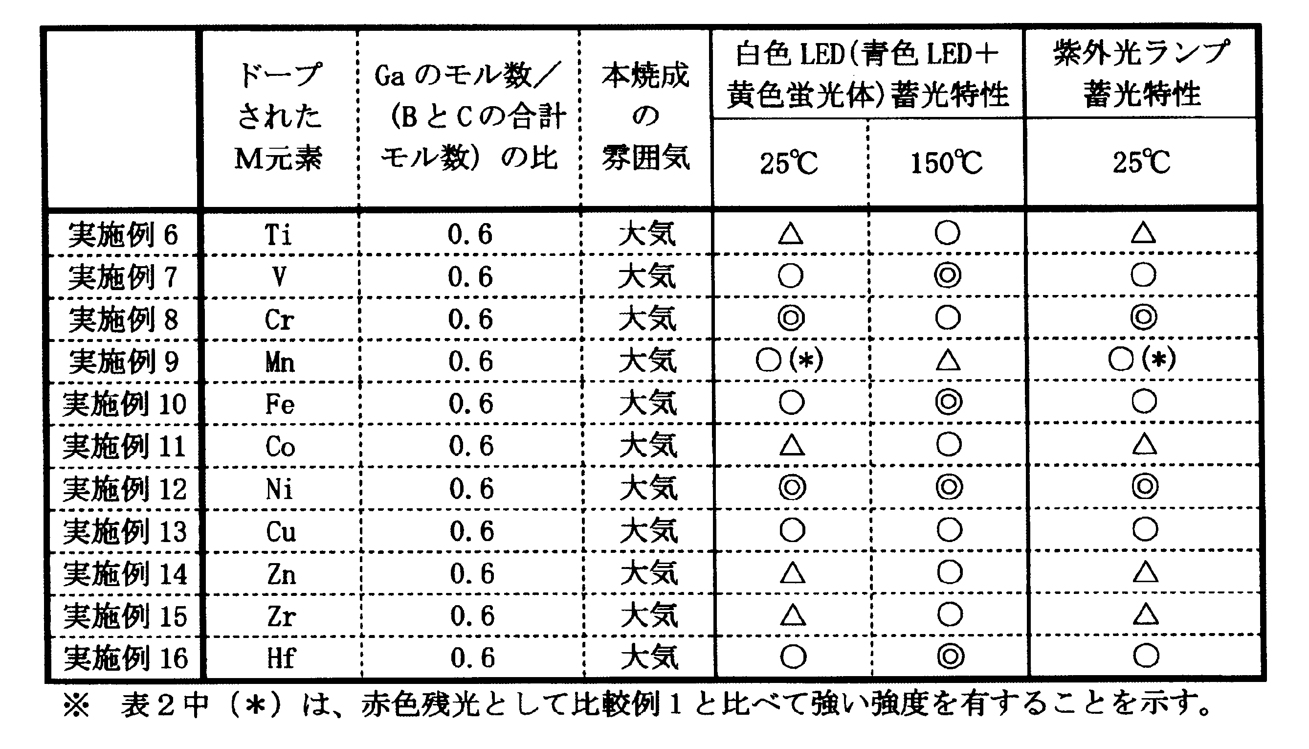
(考察)
上記結果からも明らかなように、実施例6~16の蛍光体は、紫外光励起による長残光特性に優れ、且つ、青色光励起による長残光特性にも優れる。
上記結果からも明らかなように、実施例6~16の蛍光体は、紫外光励起による長残光特性に優れ、且つ、青色光励起による長残光特性にも優れる。
Claims (5)
- 下記組成式 (1):
A3B2C3O12 (1)
(式中、
Aは、(i) Mg、Ca、Sr、La、Gd、Tb、Lu、及びYからなる群から選ばれた少なくとも1種の元素、並びに、(ii)Ceであり、
BはAl、Ga、Sc、In、Mg、Lu、及びYからなる群から選ばれた少なくとも1種の元素であり、
CはSi、Ge、Al及びGaからなる群から選ばれた少なくとも1種の元素である)で表される化合物に、
Ti、V、Cr、Mn、Fe、Co、Ni、Cu、Zn、Zr、Hf、Si、Yb、Eu、Pr及びTbからなる群から選ばれた少なくとも1種の金属元素がドープされていることを特徴とする蛍光体。 - 前記金属元素のドープ量が、前記式(1)で表される化合物に対して0.001~5モル%である、請求項1に記載の蛍光体。
- 前記(i)の元素と前記(ii)Ceとのモル比が、0.9999:0.0001~0.95:0.05である、請求項1又は2に記載の蛍光体。
- 蓄光蛍光体、白色LED、蓄光セラミックス、蓄光樹脂、蓄光塗料、蓄光式避難誘導システム、又はバイオイメージング用マーカーに用いられる、請求項1~3のいずれかに記載の蛍光体。
- 下記組成式 (1):
A3B2C3O12 (1)
(式中、
Aは、(i) Mg、Ca、Sr、La、Gd、Tb、Lu、及びYからなる群から選ばれた少なくとも1種の元素、並びに、(ii)Ceであり、
BはAl、Ga、Sc、In、Mg、Lu、及びYからなる群から選ばれた少なくとも1種の元素であり、
CはSi、Ge、Al及びGaからなる群から選ばれた少なくとも1種の元素である)で表される化合物に、
Ti、V、Cr、Mn、Fe、Co、Ni、Cu、Zn、Zr、Hf、Si、Yb、Eu、Pr及びTbからなる群から選ばれた少なくとも1種の金属元素がドープされている蛍光体の製造方法であって、
(1) 前記(i)の元素含有化合物、B元素含有化合物、C元素含有化合物、Ce含有化合物及び前記金属元素含有化合物を含む組成物を用意する工程1、及び
(2) 前記組成物を1200~1800℃で加熱する工程2
を順に含む、蛍光体の製造方法。
Priority Applications (1)
| Application Number | Priority Date | Filing Date | Title |
|---|---|---|---|
| JP2015555055A JPWO2015099145A1 (ja) | 2013-12-27 | 2014-12-26 | 蛍光体、及び蛍光体の製造方法 |
Applications Claiming Priority (4)
| Application Number | Priority Date | Filing Date | Title |
|---|---|---|---|
| JP2013-273573 | 2013-12-27 | ||
| JP2013273573 | 2013-12-27 | ||
| JP2014-079558 | 2014-04-08 | ||
| JP2014079558 | 2014-04-08 |
Publications (1)
| Publication Number | Publication Date |
|---|---|
| WO2015099145A1 true WO2015099145A1 (ja) | 2015-07-02 |
Family
ID=53478984
Family Applications (1)
| Application Number | Title | Priority Date | Filing Date |
|---|---|---|---|
| PCT/JP2014/084590 Ceased WO2015099145A1 (ja) | 2013-12-27 | 2014-12-26 | 蛍光体、及び蛍光体の製造方法 |
Country Status (2)
| Country | Link |
|---|---|
| JP (1) | JPWO2015099145A1 (ja) |
| WO (1) | WO2015099145A1 (ja) |
Cited By (25)
| Publication number | Priority date | Publication date | Assignee | Title |
|---|---|---|---|---|
| JP2016121226A (ja) * | 2014-12-24 | 2016-07-07 | 日亜化学工業株式会社 | 近赤外発光蛍光体 |
| CN105969355A (zh) * | 2016-05-10 | 2016-09-28 | 甘肃稀土新材料股份有限公司 | 一种黄绿色荧光粉及其制备方法 |
| DE102015015985A1 (de) | 2015-12-10 | 2017-06-14 | Janet Arras | Mittel und Methode zur multifunktionalen Markierung einer Straßenfahrbahn |
| WO2018043323A1 (ja) * | 2016-08-31 | 2018-03-08 | 出光興産株式会社 | 新規ガーネット化合物、それを含有する焼結体及びスパッタリングターゲット |
| CN108484168A (zh) * | 2018-03-27 | 2018-09-04 | 中国科学院上海硅酸盐研究所 | 一种红色透明荧光陶瓷及其制备方法 |
| JP2018525669A (ja) * | 2015-07-24 | 2018-09-06 | スリーエム イノベイティブ プロパティズ カンパニー | 熱拡散層を有する反射性積層体 |
| CN109987932A (zh) * | 2018-01-02 | 2019-07-09 | 上海航空电器有限公司 | 用于白光照明的复相荧光陶瓷、制备方法及光源装置 |
| JP2020166012A (ja) * | 2019-03-28 | 2020-10-08 | パナソニックIpマネジメント株式会社 | 波長変換部材、光源装置、及び照明装置 |
| CN112552912A (zh) * | 2020-12-16 | 2021-03-26 | 江西理工大学 | 一种新型Cr3+掺杂宽带近红外荧光粉、制备及应用 |
| CN113213933A (zh) * | 2021-03-19 | 2021-08-06 | 浙江大学 | 一种宽带近红外荧光陶瓷及其制备方法和应用 |
| CN113826226A (zh) * | 2019-05-27 | 2021-12-21 | 松下知识产权经营株式会社 | 发光装置以及使用了该发光装置的电子设备及检验方法 |
| CH717559A1 (de) * | 2020-06-22 | 2021-12-30 | Brevalor Sarl | Lichtdurchlässiges nachleuchtend lumineszierendes Objekt und dessen Anwendung. |
| CN114015445A (zh) * | 2021-12-20 | 2022-02-08 | 广东工业大学 | 一种石榴石结构近红外荧光材料及其制备方法和应用 |
| CN114250073A (zh) * | 2020-09-25 | 2022-03-29 | 厦门稀土材料研究所 | 一种在近红外长余辉发光的纳米材料及其制备方法和应用 |
| CN114276807A (zh) * | 2021-12-27 | 2022-04-05 | 北京科技大学 | 一种近红外荧光粉和制备方法以及使用其的近红外光源 |
| CN114836211A (zh) * | 2022-05-11 | 2022-08-02 | 合肥工业大学 | 一种Cu离子掺杂镓锗酸盐基绿色长余辉材料及其制备方法 |
| CN114891500A (zh) * | 2022-04-29 | 2022-08-12 | 安徽三联学院 | 一种铕和碱金属离子共掺杂石榴石结构红色发光材料及其制备方法 |
| CN114958354A (zh) * | 2022-04-29 | 2022-08-30 | 安徽三联学院 | 一种Eu2+激活的碱土金属化合物红色发光材料及其制备方法 |
| CN116639975A (zh) * | 2023-02-24 | 2023-08-25 | 河南工业大学 | 蓝光激发的宽半高宽近红外荧光陶瓷及其制备方法和应用 |
| CN116656354A (zh) * | 2023-06-01 | 2023-08-29 | 重庆邮电大学 | 一种铁离子激活锡镓酸盐宽带近红外长余辉发光材料及其制备方法和应用 |
| CN117101720A (zh) * | 2023-06-30 | 2023-11-24 | 喀什大学 | 一种核壳结构的PLNPs@COFs复合光催化材料的制备方法及其应用 |
| CN117142847A (zh) * | 2023-08-30 | 2023-12-01 | 河南工业大学 | 一种反常热猝灭近红外荧光陶瓷及其制备方法与应用 |
| CN117186891A (zh) * | 2023-08-21 | 2023-12-08 | 中国科学院上海硅酸盐研究所 | 一种高品质因子的过渡金属元素掺杂石榴石构型铝酸盐闪烁材料及其制备方法和应用 |
| CN120519151A (zh) * | 2025-07-25 | 2025-08-22 | 西安建筑科技大学 | 一种自激活长余辉一维晶体棒发光材料及制备方法和应用 |
| WO2025234446A1 (ja) * | 2024-05-08 | 2025-11-13 | 国立大学法人北陸先端科学技術大学院大学 | 化合物、化合物の製造方法 |
Citations (15)
| Publication number | Priority date | Publication date | Assignee | Title |
|---|---|---|---|---|
| CN1169587A (zh) * | 1996-06-28 | 1998-01-07 | 电子科技大学 | 高亮度、高分辨率单晶彩色投影显示管 |
| CN1254747A (zh) * | 1998-11-23 | 2000-05-31 | 中国科学院长春物理研究所 | 稀土石榴石绿色荧光体及制备方法 |
| JP2003505582A (ja) * | 1999-07-23 | 2003-02-12 | パテント−トロイハント−ゲゼルシヤフト フユール エレクトリツシエ グリユーラムペン ミツト ベシユレンクテル ハフツング | 光源用発光物質および発光物質を有する光源 |
| CN1482208A (zh) * | 2002-09-13 | 2004-03-17 | 北京有色金属研究总院 | 一种蓝光激发的白色led用荧光粉及其制造方法 |
| JP2005150691A (ja) * | 2003-08-28 | 2005-06-09 | Mitsubishi Chemicals Corp | 発光装置及び蛍光体 |
| CN1818016A (zh) * | 2005-11-28 | 2006-08-16 | 常熟市江南荧光材料有限公司 | 白光led用钇铝石榴石发光材料的合成方法 |
| JP2006233158A (ja) * | 2005-02-28 | 2006-09-07 | Kasei Optonix Co Ltd | Ce付活希土類アルミン酸塩系蛍光体及びこれを用いた発光素子 |
| JP2006520836A (ja) * | 2003-03-17 | 2006-09-14 | コーニンクレッカ フィリップス エレクトロニクス エヌ ヴィ | 放射源及び蛍光物質を有する照明システム |
| JP2006265542A (ja) * | 2005-02-28 | 2006-10-05 | Mitsubishi Chemicals Corp | 蛍光体及びその製造方法並びにそれを使用した発光装置 |
| JP2007515527A (ja) * | 2003-12-22 | 2007-06-14 | パテント−トロイハント−ゲゼルシヤフト フユール エレクトリツシエ グリユーラムペン ミツト ベシユレンクテル ハフツング | 蛍光体及びかかる蛍光体を有する光源 |
| JP2008506001A (ja) * | 2004-07-06 | 2008-02-28 | アコル テクノロジーズ ソシエテ アノニム | 白色発光ダイオードシステムのための波長シフト組成物 |
| US20080246005A1 (en) * | 2007-04-04 | 2008-10-09 | Soshchin Naum | Phosphor for blue-light led, blue-light led using same |
| JP2009079094A (ja) * | 2007-09-25 | 2009-04-16 | Toshiba Corp | 蛍光体およびそれを用いたledランプ |
| CN101962547A (zh) * | 2010-10-19 | 2011-02-02 | 四川大学 | 一种白光led用黄色荧光粉及其制备方法 |
| CN102492424A (zh) * | 2011-11-16 | 2012-06-13 | 中国科学院长春应用化学研究所 | 一种低色温石榴石基的荧光发光材料及其制备方法 |
-
2014
- 2014-12-26 WO PCT/JP2014/084590 patent/WO2015099145A1/ja not_active Ceased
- 2014-12-26 JP JP2015555055A patent/JPWO2015099145A1/ja active Pending
Patent Citations (15)
| Publication number | Priority date | Publication date | Assignee | Title |
|---|---|---|---|---|
| CN1169587A (zh) * | 1996-06-28 | 1998-01-07 | 电子科技大学 | 高亮度、高分辨率单晶彩色投影显示管 |
| CN1254747A (zh) * | 1998-11-23 | 2000-05-31 | 中国科学院长春物理研究所 | 稀土石榴石绿色荧光体及制备方法 |
| JP2003505582A (ja) * | 1999-07-23 | 2003-02-12 | パテント−トロイハント−ゲゼルシヤフト フユール エレクトリツシエ グリユーラムペン ミツト ベシユレンクテル ハフツング | 光源用発光物質および発光物質を有する光源 |
| CN1482208A (zh) * | 2002-09-13 | 2004-03-17 | 北京有色金属研究总院 | 一种蓝光激发的白色led用荧光粉及其制造方法 |
| JP2006520836A (ja) * | 2003-03-17 | 2006-09-14 | コーニンクレッカ フィリップス エレクトロニクス エヌ ヴィ | 放射源及び蛍光物質を有する照明システム |
| JP2005150691A (ja) * | 2003-08-28 | 2005-06-09 | Mitsubishi Chemicals Corp | 発光装置及び蛍光体 |
| JP2007515527A (ja) * | 2003-12-22 | 2007-06-14 | パテント−トロイハント−ゲゼルシヤフト フユール エレクトリツシエ グリユーラムペン ミツト ベシユレンクテル ハフツング | 蛍光体及びかかる蛍光体を有する光源 |
| JP2008506001A (ja) * | 2004-07-06 | 2008-02-28 | アコル テクノロジーズ ソシエテ アノニム | 白色発光ダイオードシステムのための波長シフト組成物 |
| JP2006233158A (ja) * | 2005-02-28 | 2006-09-07 | Kasei Optonix Co Ltd | Ce付活希土類アルミン酸塩系蛍光体及びこれを用いた発光素子 |
| JP2006265542A (ja) * | 2005-02-28 | 2006-10-05 | Mitsubishi Chemicals Corp | 蛍光体及びその製造方法並びにそれを使用した発光装置 |
| CN1818016A (zh) * | 2005-11-28 | 2006-08-16 | 常熟市江南荧光材料有限公司 | 白光led用钇铝石榴石发光材料的合成方法 |
| US20080246005A1 (en) * | 2007-04-04 | 2008-10-09 | Soshchin Naum | Phosphor for blue-light led, blue-light led using same |
| JP2009079094A (ja) * | 2007-09-25 | 2009-04-16 | Toshiba Corp | 蛍光体およびそれを用いたledランプ |
| CN101962547A (zh) * | 2010-10-19 | 2011-02-02 | 四川大学 | 一种白光led用黄色荧光粉及其制备方法 |
| CN102492424A (zh) * | 2011-11-16 | 2012-06-13 | 中国科学院长春应用化学研究所 | 一种低色温石榴石基的荧光发光材料及其制备方法 |
Non-Patent Citations (1)
| Title |
|---|
| HAN, TAO. ET AL: "Chemical substitution effects of elements on photoluminescence properties of YAG:Ce phosphors using orthogonal experimental design", OPTICAL MATERIALS, vol. 34, no. 9, 2012, pages 1618 - 1621, XP028503158, DOI: doi:10.1016/j.optmat.2012.03.035 * |
Cited By (38)
| Publication number | Priority date | Publication date | Assignee | Title |
|---|---|---|---|---|
| JP2016121226A (ja) * | 2014-12-24 | 2016-07-07 | 日亜化学工業株式会社 | 近赤外発光蛍光体 |
| JP2018525669A (ja) * | 2015-07-24 | 2018-09-06 | スリーエム イノベイティブ プロパティズ カンパニー | 熱拡散層を有する反射性積層体 |
| US11125921B2 (en) | 2015-07-24 | 2021-09-21 | 3M Innovative Properties Company | Reflective stack with heat spreading layer |
| US11726238B2 (en) | 2015-07-24 | 2023-08-15 | 3M Innovative Properties Company | Reflective stack with heat spreading layer |
| DE102015015985A1 (de) | 2015-12-10 | 2017-06-14 | Janet Arras | Mittel und Methode zur multifunktionalen Markierung einer Straßenfahrbahn |
| CN105969355A (zh) * | 2016-05-10 | 2016-09-28 | 甘肃稀土新材料股份有限公司 | 一种黄绿色荧光粉及其制备方法 |
| WO2018043323A1 (ja) * | 2016-08-31 | 2018-03-08 | 出光興産株式会社 | 新規ガーネット化合物、それを含有する焼結体及びスパッタリングターゲット |
| US11987504B2 (en) | 2016-08-31 | 2024-05-21 | Idemitsu Kosan Co., Ltd. | Garnet compound, sintered body and sputtering target containing same |
| JPWO2018043323A1 (ja) * | 2016-08-31 | 2018-09-06 | 出光興産株式会社 | 新規ガーネット化合物、それを含有する焼結体及びスパッタリングターゲット |
| CN109641757A (zh) * | 2016-08-31 | 2019-04-16 | 出光兴产株式会社 | 新型石榴石型化合物、含有该化合物的烧结体以及溅射靶 |
| KR20190041465A (ko) * | 2016-08-31 | 2019-04-22 | 이데미쓰 고산 가부시키가이샤 | 신규 가닛 화합물, 그것을 함유하는 소결체 및 스퍼터링 타깃 |
| KR102475939B1 (ko) | 2016-08-31 | 2022-12-08 | 이데미쓰 고산 가부시키가이샤 | 신규 가닛 화합물, 그것을 함유하는 소결체 및 스퍼터링 타깃 |
| US11447398B2 (en) | 2016-08-31 | 2022-09-20 | Idemitsu Kosan Co., Ltd. | Garnet compound, sintered body and sputtering target containing same |
| CN109987932A (zh) * | 2018-01-02 | 2019-07-09 | 上海航空电器有限公司 | 用于白光照明的复相荧光陶瓷、制备方法及光源装置 |
| CN109987932B (zh) * | 2018-01-02 | 2022-08-09 | 上海航空电器有限公司 | 用于白光照明的复相荧光陶瓷、制备方法及光源装置 |
| CN108484168A (zh) * | 2018-03-27 | 2018-09-04 | 中国科学院上海硅酸盐研究所 | 一种红色透明荧光陶瓷及其制备方法 |
| JP2020166012A (ja) * | 2019-03-28 | 2020-10-08 | パナソニックIpマネジメント株式会社 | 波長変換部材、光源装置、及び照明装置 |
| JP7220363B2 (ja) | 2019-03-28 | 2023-02-10 | パナソニックIpマネジメント株式会社 | 波長変換部材、光源装置、及び照明装置 |
| CN113826226A (zh) * | 2019-05-27 | 2021-12-21 | 松下知识产权经营株式会社 | 发光装置以及使用了该发光装置的电子设备及检验方法 |
| CH717559A1 (de) * | 2020-06-22 | 2021-12-30 | Brevalor Sarl | Lichtdurchlässiges nachleuchtend lumineszierendes Objekt und dessen Anwendung. |
| CN114250073A (zh) * | 2020-09-25 | 2022-03-29 | 厦门稀土材料研究所 | 一种在近红外长余辉发光的纳米材料及其制备方法和应用 |
| CN112552912A (zh) * | 2020-12-16 | 2021-03-26 | 江西理工大学 | 一种新型Cr3+掺杂宽带近红外荧光粉、制备及应用 |
| CN113213933B (zh) * | 2021-03-19 | 2022-04-08 | 浙江大学 | 一种宽带近红外荧光陶瓷及其制备方法和应用 |
| CN113213933A (zh) * | 2021-03-19 | 2021-08-06 | 浙江大学 | 一种宽带近红外荧光陶瓷及其制备方法和应用 |
| CN114015445A (zh) * | 2021-12-20 | 2022-02-08 | 广东工业大学 | 一种石榴石结构近红外荧光材料及其制备方法和应用 |
| CN114276807A (zh) * | 2021-12-27 | 2022-04-05 | 北京科技大学 | 一种近红外荧光粉和制备方法以及使用其的近红外光源 |
| CN114891500A (zh) * | 2022-04-29 | 2022-08-12 | 安徽三联学院 | 一种铕和碱金属离子共掺杂石榴石结构红色发光材料及其制备方法 |
| CN114958354A (zh) * | 2022-04-29 | 2022-08-30 | 安徽三联学院 | 一种Eu2+激活的碱土金属化合物红色发光材料及其制备方法 |
| CN114836211A (zh) * | 2022-05-11 | 2022-08-02 | 合肥工业大学 | 一种Cu离子掺杂镓锗酸盐基绿色长余辉材料及其制备方法 |
| CN114836211B (zh) * | 2022-05-11 | 2023-08-18 | 合肥工业大学 | 一种Cu离子掺杂镓锗酸盐基绿色长余辉材料及其制备方法 |
| CN116639975A (zh) * | 2023-02-24 | 2023-08-25 | 河南工业大学 | 蓝光激发的宽半高宽近红外荧光陶瓷及其制备方法和应用 |
| CN116656354A (zh) * | 2023-06-01 | 2023-08-29 | 重庆邮电大学 | 一种铁离子激活锡镓酸盐宽带近红外长余辉发光材料及其制备方法和应用 |
| CN116656354B (zh) * | 2023-06-01 | 2024-02-23 | 重庆邮电大学 | 一种铁离子激活锡镓酸盐宽带近红外长余辉发光材料及其制备方法和应用 |
| CN117101720A (zh) * | 2023-06-30 | 2023-11-24 | 喀什大学 | 一种核壳结构的PLNPs@COFs复合光催化材料的制备方法及其应用 |
| CN117186891A (zh) * | 2023-08-21 | 2023-12-08 | 中国科学院上海硅酸盐研究所 | 一种高品质因子的过渡金属元素掺杂石榴石构型铝酸盐闪烁材料及其制备方法和应用 |
| CN117142847A (zh) * | 2023-08-30 | 2023-12-01 | 河南工业大学 | 一种反常热猝灭近红外荧光陶瓷及其制备方法与应用 |
| WO2025234446A1 (ja) * | 2024-05-08 | 2025-11-13 | 国立大学法人北陸先端科学技術大学院大学 | 化合物、化合物の製造方法 |
| CN120519151A (zh) * | 2025-07-25 | 2025-08-22 | 西安建筑科技大学 | 一种自激活长余辉一维晶体棒发光材料及制备方法和应用 |
Also Published As
| Publication number | Publication date |
|---|---|
| JPWO2015099145A1 (ja) | 2017-03-23 |
Similar Documents
| Publication | Publication Date | Title |
|---|---|---|
| WO2015099145A1 (ja) | 蛍光体、及び蛍光体の製造方法 | |
| US7189340B2 (en) | Phosphor, light emitting device using phosphor, and display and lighting system using light emitting device | |
| TWI716401B (zh) | 磷光體及磷光體轉換發光裝置 | |
| TW201708503A (zh) | 磷光體及磷光體轉換發光裝置 | |
| TW201404868A (zh) | 鹼土類金屬矽酸鹽螢光體及其製造方法 | |
| US20140376205A1 (en) | Phosphor and light-emitting device using the same | |
| TW201446938A (zh) | 磷光體 | |
| TWI551668B (zh) | 改良式砲彈發光材料及其製造方法與光源 | |
| JP6129649B2 (ja) | アップコンバージョン蛍光体及びその製造方法 | |
| JP2005243699A (ja) | 発光素子、及び画像表示装置、並びに照明装置 | |
| Ghadamyari et al. | Preparation and characterization of YAG microspheres doped with Eu2+/Eu3+ for broad band emission | |
| US9068117B2 (en) | Phosphor material and light-emitting device | |
| JP6741614B2 (ja) | 希土類付活アルカリ土類ケイ酸塩化合物残光性蛍光体 | |
| EP3085752B1 (en) | Luminescent material comprising a strontium aluminate matrix | |
| JP2014189592A (ja) | 蛍光体及び、蛍光体含有組成物、発光装置、画像表示装置及び照明装置 | |
| CN114574205B (zh) | 一种锑铝酸盐荧光粉及其制备方法与应用 | |
| JP5774297B2 (ja) | 蓄光性蛍光体及びその製造方法 | |
| JP6519746B2 (ja) | 蛍光体材料及び発光装置 | |
| JP6190941B2 (ja) | アップコンバージョン蛍光体 | |
| Parayil et al. | Defect-engineered Mn 2+, Ga 3+ co-doped Li 2 ZnGeO 4 phosphors exhibiting long-lasting green luminescence for advanced optoelectronic applications | |
| JP6099126B2 (ja) | 蛍光体、その製造方法及び発光装置 | |
| JP5674001B2 (ja) | 無機酸化物蛍光体及びその製造方法並びに発光装置 | |
| JP6112531B2 (ja) | 赤色蓄光蛍光体及びその製造方法 | |
| CN104877684A (zh) | 一种氟氧化物荧光粉及其制备方法 | |
| Ghadamyari et al. | Open Ceramics |
Legal Events
| Date | Code | Title | Description |
|---|---|---|---|
| 121 | Ep: the epo has been informed by wipo that ep was designated in this application |
Ref document number: 14874774 Country of ref document: EP Kind code of ref document: A1 |
|
| ENP | Entry into the national phase |
Ref document number: 2015555055 Country of ref document: JP Kind code of ref document: A |
|
| NENP | Non-entry into the national phase |
Ref country code: DE |
|
| 122 | Ep: pct application non-entry in european phase |
Ref document number: 14874774 Country of ref document: EP Kind code of ref document: A1 |