WO2015087900A1 - 無段変速機の制御装置 - Google Patents
無段変速機の制御装置 Download PDFInfo
- Publication number
- WO2015087900A1 WO2015087900A1 PCT/JP2014/082641 JP2014082641W WO2015087900A1 WO 2015087900 A1 WO2015087900 A1 WO 2015087900A1 JP 2014082641 W JP2014082641 W JP 2014082641W WO 2015087900 A1 WO2015087900 A1 WO 2015087900A1
- Authority
- WO
- WIPO (PCT)
- Prior art keywords
- engine
- primary
- continuously variable
- clutch
- transmission
- Prior art date
Links
Images


Classifications
-
- F—MECHANICAL ENGINEERING; LIGHTING; HEATING; WEAPONS; BLASTING
- F16—ENGINEERING ELEMENTS AND UNITS; GENERAL MEASURES FOR PRODUCING AND MAINTAINING EFFECTIVE FUNCTIONING OF MACHINES OR INSTALLATIONS; THERMAL INSULATION IN GENERAL
- F16H—GEARING
- F16H61/00—Control functions within control units of change-speed- or reversing-gearings for conveying rotary motion ; Control of exclusively fluid gearing, friction gearing, gearings with endless flexible members or other particular types of gearing
- F16H61/66—Control functions within control units of change-speed- or reversing-gearings for conveying rotary motion ; Control of exclusively fluid gearing, friction gearing, gearings with endless flexible members or other particular types of gearing specially adapted for continuously variable gearings
- F16H61/662—Control functions within control units of change-speed- or reversing-gearings for conveying rotary motion ; Control of exclusively fluid gearing, friction gearing, gearings with endless flexible members or other particular types of gearing specially adapted for continuously variable gearings with endless flexible members
- F16H61/66272—Control functions within control units of change-speed- or reversing-gearings for conveying rotary motion ; Control of exclusively fluid gearing, friction gearing, gearings with endless flexible members or other particular types of gearing specially adapted for continuously variable gearings with endless flexible members characterised by means for controlling the torque transmitting capability of the gearing
-
- B—PERFORMING OPERATIONS; TRANSPORTING
- B60—VEHICLES IN GENERAL
- B60W—CONJOINT CONTROL OF VEHICLE SUB-UNITS OF DIFFERENT TYPE OR DIFFERENT FUNCTION; CONTROL SYSTEMS SPECIALLY ADAPTED FOR HYBRID VEHICLES; ROAD VEHICLE DRIVE CONTROL SYSTEMS FOR PURPOSES NOT RELATED TO THE CONTROL OF A PARTICULAR SUB-UNIT
- B60W10/00—Conjoint control of vehicle sub-units of different type or different function
- B60W10/04—Conjoint control of vehicle sub-units of different type or different function including control of propulsion units
- B60W10/06—Conjoint control of vehicle sub-units of different type or different function including control of propulsion units including control of combustion engines
-
- B—PERFORMING OPERATIONS; TRANSPORTING
- B60—VEHICLES IN GENERAL
- B60W—CONJOINT CONTROL OF VEHICLE SUB-UNITS OF DIFFERENT TYPE OR DIFFERENT FUNCTION; CONTROL SYSTEMS SPECIALLY ADAPTED FOR HYBRID VEHICLES; ROAD VEHICLE DRIVE CONTROL SYSTEMS FOR PURPOSES NOT RELATED TO THE CONTROL OF A PARTICULAR SUB-UNIT
- B60W10/00—Conjoint control of vehicle sub-units of different type or different function
- B60W10/10—Conjoint control of vehicle sub-units of different type or different function including control of change-speed gearings
- B60W10/101—Infinitely variable gearings
- B60W10/107—Infinitely variable gearings with endless flexible members
-
- B—PERFORMING OPERATIONS; TRANSPORTING
- B60—VEHICLES IN GENERAL
- B60W—CONJOINT CONTROL OF VEHICLE SUB-UNITS OF DIFFERENT TYPE OR DIFFERENT FUNCTION; CONTROL SYSTEMS SPECIALLY ADAPTED FOR HYBRID VEHICLES; ROAD VEHICLE DRIVE CONTROL SYSTEMS FOR PURPOSES NOT RELATED TO THE CONTROL OF A PARTICULAR SUB-UNIT
- B60W10/00—Conjoint control of vehicle sub-units of different type or different function
- B60W10/10—Conjoint control of vehicle sub-units of different type or different function including control of change-speed gearings
- B60W10/11—Stepped gearings
-
- F—MECHANICAL ENGINEERING; LIGHTING; HEATING; WEAPONS; BLASTING
- F16—ENGINEERING ELEMENTS AND UNITS; GENERAL MEASURES FOR PRODUCING AND MAINTAINING EFFECTIVE FUNCTIONING OF MACHINES OR INSTALLATIONS; THERMAL INSULATION IN GENERAL
- F16H—GEARING
- F16H61/00—Control functions within control units of change-speed- or reversing-gearings for conveying rotary motion ; Control of exclusively fluid gearing, friction gearing, gearings with endless flexible members or other particular types of gearing
- F16H61/0021—Generation or control of line pressure
-
- F—MECHANICAL ENGINEERING; LIGHTING; HEATING; WEAPONS; BLASTING
- F16—ENGINEERING ELEMENTS AND UNITS; GENERAL MEASURES FOR PRODUCING AND MAINTAINING EFFECTIVE FUNCTIONING OF MACHINES OR INSTALLATIONS; THERMAL INSULATION IN GENERAL
- F16H—GEARING
- F16H61/00—Control functions within control units of change-speed- or reversing-gearings for conveying rotary motion ; Control of exclusively fluid gearing, friction gearing, gearings with endless flexible members or other particular types of gearing
- F16H61/70—Control functions within control units of change-speed- or reversing-gearings for conveying rotary motion ; Control of exclusively fluid gearing, friction gearing, gearings with endless flexible members or other particular types of gearing specially adapted for change-speed gearing in group arrangement, i.e. with separate change-speed gear trains arranged in series, e.g. range or overdrive-type gearing arrangements
-
- B—PERFORMING OPERATIONS; TRANSPORTING
- B60—VEHICLES IN GENERAL
- B60W—CONJOINT CONTROL OF VEHICLE SUB-UNITS OF DIFFERENT TYPE OR DIFFERENT FUNCTION; CONTROL SYSTEMS SPECIALLY ADAPTED FOR HYBRID VEHICLES; ROAD VEHICLE DRIVE CONTROL SYSTEMS FOR PURPOSES NOT RELATED TO THE CONTROL OF A PARTICULAR SUB-UNIT
- B60W30/00—Purposes of road vehicle drive control systems not related to the control of a particular sub-unit, e.g. of systems using conjoint control of vehicle sub-units, or advanced driver assistance systems for ensuring comfort, stability and safety or drive control systems for propelling or retarding the vehicle
- B60W30/18—Propelling the vehicle
- B60W30/18009—Propelling the vehicle related to particular drive situations
- B60W30/18018—Start-stop drive, e.g. in a traffic jam
-
- F—MECHANICAL ENGINEERING; LIGHTING; HEATING; WEAPONS; BLASTING
- F16—ENGINEERING ELEMENTS AND UNITS; GENERAL MEASURES FOR PRODUCING AND MAINTAINING EFFECTIVE FUNCTIONING OF MACHINES OR INSTALLATIONS; THERMAL INSULATION IN GENERAL
- F16H—GEARING
- F16H2312/00—Driving activities
- F16H2312/14—Going to, or coming from standby operation, e.g. for engine start-stop operation at traffic lights
Definitions
- the present invention relates to a control device for a continuously variable transmission applied to a vehicle that performs engine stop control (coast stop control / idle stop control).
- the gear ratio is increased to a higher side than the gear ratio at the start of the coast stop control during coast stop control in which the driving force source is stopped in the running state of the vehicle. It is disclosed to prevent shifting.
- the hydraulic pressure of the primary pulley is made substantially zero, the balance pressure control is set to the lowest speed ratio, and then the coast stop control is finished.
- the present invention has been made paying attention to the above problem, and an object of the present invention is to provide a control device for a continuously variable transmission that can suppress a decrease in starting performance when starting out of engine stop control. .
- a control device for a continuously variable transmission comprises an engine, a continuously variable transmission mechanism, a starting clutch, a mechanical oil pump, and an engine stop control means.
- a primary solenoid valve that is provided in the middle of an oil passage from the mechanical oil pump to the primary pulley and controls the hydraulic pressure to the primary pulley, and a primary current to the primary solenoid valve Transmission control means for outputting an instruction value.
- the transmission control means preliminarily closes the oil path from the mechanical oil pump to the primary pulley at least before the engine speed rises due to restart of the engine.
- the current instruction value is output to the primary solenoid valve.
- a primary current indication value that closes the oil path from the mechanical oil pump to the primary pulley in advance is output to the primary solenoid valve at least before the engine speed rises due to engine restart. Is done. Therefore, if the engine speed gradually increases as the engine restarts, the oil passage from the mechanical oil pump to the primary pulley is closed in advance before the engine speed rises, and the oil supply to the primary hydraulic chamber is stopped. It can be stopped. By stopping the oil supply to the primary hydraulic chamber, the oil flow rate from the mechanical oil pump can be used on the start clutch side, and the time required until the start clutch is engaged is shortened. Further, by stopping the oil supply to the primary hydraulic chamber, the continuously variable transmission mechanism is maintained at the lowest speed ratio, and the driving force does not decrease when starting. As a result, it is possible to suppress a decrease in the starting performance when starting from the engine stop control.
- FIG. 1 is an overall system diagram illustrating a schematic configuration of a vehicle on which a continuously variable transmission with a sub-transmission (an example of a continuously variable transmission) to which a control device according to a first embodiment is applied.
- FIG. 3 is a control block diagram illustrating a control system configuration centering on the transmission controller of the first embodiment. It is a shift map figure which shows an example of the shift map stored in the memory
- 5 is a flowchart 1 illustrating a flow of a coast stop-compatible transmission control process executed by the transmission controller according to the first embodiment.
- 6 is a flowchart 2 illustrating a flow of a coast stop-compatible transmission control process executed by the transmission controller according to the first embodiment.
- 6 is a flowchart 3 illustrating a flow of a coast stop-compatible transmission control process executed by the transmission controller according to the first embodiment.
- Coast stop control on / off of the vehicle of Example 1 CS / FLG, engine speed Ne, vehicle speed VSP, lockup clutch L / U, line pressure PL, high clutch oil pressure PH / C, low brake 6 is a time chart showing characteristics of clutch hydraulic pressure command value PL / B * and primary current command value PriSOL / I * .
- the control device for a continuously variable transmission with an auxiliary transmission includes an “overall system configuration”, a “shift control configuration using a shift map”, a “coast stop control configuration”, and a “coast stop”.
- the explanation will be divided into “corresponding transmission control configuration”.
- FIG. 1 shows a schematic configuration of a vehicle on which a continuously variable transmission with a sub-transmission to which the control device of the first embodiment is applied
- FIG. 2 shows an internal configuration of a transmission controller.
- the overall system configuration will be described below with reference to FIGS.
- the “transmission ratio” of a transmission mechanism is a value obtained by dividing the input rotational speed of the transmission mechanism by the output rotational speed of the transmission mechanism.
- “lowest speed ratio” means the maximum speed ratio of the speed change mechanism
- “highest speed ratio” means the minimum speed ratio of the speed change mechanism.
- a vehicle equipped with the continuously variable transmission with the auxiliary transmission includes an engine 1 having a starter motor 15 for starting the engine as a power source. Output rotation of the engine 1 is transmitted through a torque converter 2 having a lock-up clutch 9, a reduction gear pair 3, a continuously variable transmission (hereinafter simply referred to as “transmission 4”), a final gear pair 5, and a final reduction gear 6. Is transmitted to the drive wheel 7.
- the final gear pair 5 is provided with a parking mechanism 8 that mechanically locks the output shaft of the transmission 4 during parking.
- the vehicle also includes a mechanical oil pump 10 driven by the power of the engine 1, a hydraulic control circuit 11 that regulates the discharge pressure from the mechanical oil pump 10 and supplies the pressure to each part of the transmission 4, and a hydraulic control circuit 11, a transmission controller 12, an integrated controller 13, and an engine controller 14 are provided.
- a mechanical oil pump 10 driven by the power of the engine 1
- a hydraulic control circuit 11 that regulates the discharge pressure from the mechanical oil pump 10 and supplies the pressure to each part of the transmission 4
- a hydraulic control circuit 11 a transmission controller 12, an integrated controller 13, and an engine controller 14 are provided.
- the transmission 4 includes a belt-type continuously variable transmission mechanism (hereinafter referred to as “variator 20”) and an auxiliary transmission mechanism 30 provided in series with the variator 20.
- “provided in series” means that the variator 20 and the subtransmission mechanism 30 are provided in series in the power transmission path.
- the auxiliary transmission mechanism 30 may be directly connected to the output shaft of the variator 20 as in this example, or may be connected via another transmission or power transmission mechanism (for example, a gear train).
- the variator 20 is a belt-type continuously variable transmission mechanism including a primary pulley 21, a secondary pulley 22, and a V belt 23 wound around the pulleys 21 and 22.
- Each of the pulleys 21 and 22 is disposed with a fixed conical plate, a movable conical plate formed with a sheave surface facing the fixed conical plate, and forming a V groove between the fixed conical plate and the movable conical plate.
- a primary hydraulic chamber 23a and a secondary hydraulic chamber 23b are provided on the back surface of the plate to displace the movable conical plate in the axial direction.
- the auxiliary transmission mechanism 30 is a transmission mechanism having two forward speeds and one reverse speed.
- the subtransmission mechanism 30 is connected to a Ravigneaux type planetary gear mechanism 31 in which two planetary gear carriers are coupled, and a plurality of rotating elements constituting the Ravigneaux type planetary gear mechanism 31, and a plurality of frictions that change their linkage state.
- Fastening elements low brake 32, high clutch 33, reverse brake 34
- the gear position of the auxiliary transmission mechanism 30 is changed.
- the gear position of the subtransmission mechanism 30 is the first speed.
- the gear position of the subtransmission mechanism 30 becomes the second speed having a smaller gear ratio than the first speed.
- the reverse brake 34 is engaged and the low brake 32 and the high clutch 33 are released, the shift speed of the subtransmission mechanism 30 is reverse. In the following description, it is expressed that “the transmission 4 is in the low speed mode” when the shift speed of the auxiliary transmission mechanism 30 is the first speed, and “the transmission 4 is in the high speed mode” when the speed is the second speed.
- the transmission controller 12 includes a CPU 121, a storage device 122 including a RAM / ROM, an input interface 123, an output interface 124, and a bus 125 that interconnects them. .
- the output signal of the rotation speed sensor 42 for detecting the rotation speed (hereinafter referred to as “primary rotation speed Npri”), the output signal of the vehicle speed sensor 43 for detecting the traveling speed of the vehicle (hereinafter referred to as “vehicle speed VSP”), and the speed change.
- the output signal of the line pressure sensor 44 that detects the line pressure of the machine 4 hereinafter referred to as “line pressure PL”
- the output signal of the inhibitor switch 45 that detects the position of the select lever, and the like are input.
- the storage device 122 stores a shift control program for the transmission 4 and a shift map (FIG. 3) used in the shift control program.
- the CPU 121 reads out and executes a shift control program stored in the storage device 122, performs various arithmetic processes on various signals input via the input interface 123, generates a shift control signal, and generates the generated shift control program.
- the control signal is output to the hydraulic control circuit 11 via the output interface 124.
- Various values used in the arithmetic processing by the CPU 121 and the arithmetic results are appropriately stored in the storage device 122.
- the hydraulic control circuit 11 includes a plurality of flow paths and a plurality of hydraulic control valves.
- the hydraulic control circuit 11 switches a hydraulic pressure supply path by controlling a plurality of hydraulic control valves based on a shift control signal from the transmission controller 12. That is, the line pressure PL is adjusted from the discharge pressure generated by the mechanical oil pump 10, and the pulley pressure and the clutch pressure adjusted using the line pressure PL as the original pressure are supplied to each part of the transmission 4. Thereby, the gear ratio vRatio of the variator 20 and the gear position of the auxiliary transmission mechanism 30 are changed, and the transmission 4 is shifted.
- the integrated controller 13 performs integrated management of a plurality of in-vehicle controllers so that transmission control by the transmission controller 12 and engine control by the engine controller 14 are appropriately secured.
- the integrated controller 13 is connected to an in-vehicle controller such as the transmission controller 12 and the engine controller 14 via a CAN communication line 25 so that information can be exchanged.
- the engine controller 14 performs coast stop control for stopping the engine 1 after coast deceleration, idle stop control for stopping the engine 1 when the vehicle stops, engine start control using the starter motor 15, and the like.
- the engine controller 14 receives an output signal of an engine speed sensor 46 that detects the speed of the engine 1 (hereinafter referred to as “engine speed Ne”).
- FIG. 3 shows an example of a shift map stored in the storage device 122 of the transmission controller 12.
- a shift control configuration based on the shift map will be described with reference to FIG.
- the operating point of the transmission 4 is determined based on the vehicle speed VSP and the primary rotational speed Npri on the shift map shown in FIG.
- the slope of the line connecting the operating point of the transmission 4 and the zero point of the lower left corner of the transmission map is the overall transmission obtained by multiplying the transmission ratio of the transmission 4 (the transmission ratio vRatio of the variator 20 and the transmission ratio subRatio of the subtransmission mechanism 30). Ratio, hereinafter referred to as “through transmission ratio”).
- a shift line is set for each accelerator opening APO, and the shift of the transmission 4 is selected according to the accelerator opening APO. According to the shift line.
- the transmission 4 When the transmission 4 is in the low speed mode, the transmission 4 has a low speed mode lowest line LL / L obtained by maximizing the transmission ratio vRatio of the variator 20, and a low speed mode obtained by minimizing the transmission ratio vRatio of the variator 20. It is possible to shift between the highest line LH / L. At this time, the operating point of the transmission 4 moves in the A region and the B region.
- the transmission 4 when the transmission 4 is in the high speed mode, the transmission 4 has the highest speed line HL / L obtained by maximizing the transmission ratio vRatio of the variator 20 and the high speed obtained by minimizing the transmission ratio vRatio of the variator 20. It is possible to shift between the mode highest line HH / L. At this time, the operating point of the transmission 4 moves in the B region and the C region.
- the gear ratio of each gear stage of the sub-transmission mechanism 30 is the gear ratio corresponding to the low speed mode highest line LH / L (the low speed mode highest gear ratio) corresponding to the high speed mode lowest line HL / L ( It is set to be smaller than (high speed mode lowest gear ratio). Accordingly, the low speed mode ratio range LRE that is a range of the through speed ratio Ratio of the transmission 4 that can be taken in the low speed mode, and the high speed mode ratio range HRE that is a range of the through speed ratio Ratio of the transmission 4 that can be taken in the high speed mode. , Partially overlap.
- the transmission 4 When the operating point of the transmission 4 is in the B region (overlapping region) between the high speed mode lowest line HL / L and the low speed mode highest line LH / L, the transmission 4 is in either the low speed mode or the high speed mode.
- the mode can also be selected.
- the transmission controller 12 refers to the shift map, and sets the through speed ratio Ratio corresponding to the vehicle speed VSP and the accelerator opening APO (the driving state of the vehicle) as the ultimate through speed ratio DRatio.
- the reaching through speed ratio DRatio is a target value that the through speed ratio Ratio should finally reach in the operation state.
- the transmission controller 12 sets a target through speed ratio tRatio, which is a transient target value for causing the through speed ratio Ratio to follow the reached through speed ratio DRatio with a desired response characteristic, and the through speed ratio Ratio is the target.
- the variator 20 and the subtransmission mechanism 30 are controlled so as to coincide with the through speed ratio tRatio.
- a mode switching up shift line MU / L (1 ⁇ 2 up shift line of the subtransmission mechanism 30) for performing the upshift of the subtransmission mechanism 30 is substantially on the low speed mode highest line LH / L. It is set to overlap.
- the through speed ratio Ratio corresponding to the mode switching up speed change line MU / L is substantially equal to the low speed mode highest speed ratio LH / L.
- the mode switching down shift line MD / L (2 ⁇ 1 down shift line of the subtransmission mechanism 30) for performing the downshift of the subtransmission mechanism 30 is on the high-speed mode lowest line HL / L. It is set so as to be almost overlapped.
- the through speed ratio Ratio corresponding to the mode switching down speed change line MD / L is substantially equal to the high speed mode lowest speed ratio HL / L.
- the transmission controller 12 performs the mode switching shift control when it is changed at or when it matches the mode switching gear ratio mRatio.
- the transmission controller 12 shifts the auxiliary transmission mechanism 30 and changes the transmission ratio vRatio of the variator 20 in a direction opposite to the direction in which the transmission ratio subRatio of the auxiliary transmission mechanism 30 changes.
- “cooperative control” for coordinating two shifts is performed.
- the transmission controller 12 issues a 1 ⁇ 2 upshift determination, changes the gear position of the subtransmission mechanism 30 from the first gear to the second gear, and maximizes the gear ratio vRatio of the variator 20. Change from high gear ratio to low gear ratio.
- the target through speed ratio tRatio of the transmission 4 crosses the mode switching down shift line MD / L from the B area side toward the A area side, or from the B area side to the mode switching down shift line MD / L.
- the transmission controller 12 issues a 2 ⁇ 1 downshift determination, changes the gear position of the subtransmission mechanism 30 from the second speed to the first speed, and changes the speed ratio vRatio of the variator 20 from the lowest speed ratio. Change to the gear ratio side.
- the reason for performing the “cooperative control” for changing the speed ratio vRatio of the variator 20 at the time of the mode change up shift or the mode change down shift is the change in the input rotational speed caused by the step of the through speed ratio Ratio of the transmission 4. This is because the driver's uncomfortable feeling can be suppressed, and the shift shock of the auxiliary transmission mechanism 30 can be reduced.
- the engine controller 14 In order to suppress the fuel consumption as much as possible, the engine controller 14 according to the first embodiment performs an engine operation while the vehicle is coasting (during coasting) in addition to “idle stop control” that stops the engine 1 while the vehicle is stopped. “Coast stop control” is performed to stop 1.
- the “coast stop control” is a control for suppressing the fuel consumption by automatically stopping the engine 1 while the vehicle is coasting in a low vehicle speed range.
- the “coast stop control” and the “fuel cut control” executed when the accelerator is off are common in that the fuel supply to the engine 1 is stopped. However, the normal “fuel cut control” is executed at a relatively high speed, and the lock-up clutch 9 of the torque converter 2 is engaged to ensure engine braking.
- the “coast stop control” is executed during coasting at a relatively low speed immediately before the vehicle stops, and differs in that the lockup clutch 9 is released to stop the rotation of the engine 1.
- the engine controller 14 determines, for example, the following conditions (a) to (e).
- (a): The foot is released from the accelerator pedal (accelerator opening APO 0)
- the high speed mode (second speed) by the engagement of the high clutch 33 is selected.
- the mechanical oil pump 10 that generates hydraulic pressure by the driving force of the engine 1 also stops gradually as the engine speed decreases, and the discharge pressure from the mechanical oil pump 10 is changed to the hydraulic control circuit 11. No longer supplied.
- hydraulic pressure is originally required for the belt clamping force by the pulleys of the variator 20 and the engagement of the frictional engagement elements of the auxiliary transmission mechanism 30.
- an oil pump in addition to an engine-driven mechanical oil pump, an electric oil pump that supplements hydraulic pressure while the engine is stopped is mounted. .
- the electric oil pump is abolished mainly for the purpose of reducing the system cost and only the mechanical oil pump 10 is installed. It becomes necessary to perform stop-compatible transmission control. Therefore, the coast stop corresponding transmission control is performed on the transmission controller 12 side based on input information such as the coast stop control flag CS / FLG and the engine speed Ne.
- the start condition of the coast stop control includes the high speed mode selection condition (e) as described above, when the coast stop control is started, the engaged high clutch 33 is released.
- the coast stop control is finished while the vehicle is stopped, the vehicle starts with the lowest gear ratio in the low-speed mode, so the low brake 32 is engaged as a starting clutch.
- the start condition of the coast stop control includes the high speed mode selection condition (e)
- the coast stop control is not started if the low brake 32 is engaged during traveling.
- idle stop control is performed.
- the low brake 32 that is engaged by the selection of the low speed mode is released after the vehicle stops.
- the idle stop control is completed, the low brake 32 is engaged as a starting clutch because the vehicle starts at the lowest speed ratio in the low speed mode, as is the case with the coast stop control.
- the low brake 32 has a multi-plate friction engagement element configuration and has a piston oil chamber 32b defined by a brake piston 32a.
- the transmission hydraulic pressure to the primary hydraulic chamber 23 a of the primary pulley 21 and the secondary hydraulic chamber 23 b of the secondary pulley 22 and the clutch hydraulic pressure to the low brake 32 are based on the discharge pressure from the mechanical oil pump 10 driven by the engine 1.
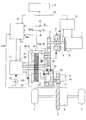
- the hydraulic control circuit 11 includes a pressure regulator valve 111, a pilot valve 112, a low brake solenoid valve 113, an accumulator 114, a primary solenoid valve 118, and a primary control valve 119.
- the pressure regulator valve 111 is a valve that regulates the line pressure PL from the pump discharge pressure, and includes a line pressure port 111a, a closing port 111b, and a drain port 111c.
- a spring force and an operation signal pressure generated by a line pressure solenoid act on one end side of the valve spool 111d, and a feedback pressure acts on the other end side.
- a line pressure oil passage 115 is connected to the line pressure port 111a, and the line pressure oil passage 115 is connected to the secondary hydraulic chamber 23b without a valve.
- the line pressure oil passage 115 is connected to the line pressure port 112 a of the pilot valve 112 and the line pressure port 119 a of the primary control valve 119.
- the pilot valve 112 is a valve that generates a pilot pressure Pp in which the upper limit of the line pressure PL is regulated, and includes a line pressure port 112a, a pilot pressure port 112b, and a drain port 112c.
- a spring force acts on one end side of the valve spool 111d, and a feedback pressure acts on the other end side.
- a pilot pressure oil passage 116 is connected to the pilot pressure port 112b.
- the pilot pressure oil passage 116 is provided with an orifice 116a and a one-way valve 116b in parallel.
- the low brake solenoid valve 113 is a valve that regulates the low brake hydraulic pressure PL / B using the pilot pressure Pp as a base pressure, and has a pilot pressure port 113a, a low brake pressure port 113b, and a drain port 113c.
- a spring force and feedback pressure act on one end side of the valve spool 113d, and a solenoid force acts on the other end side. If there is no action of the solenoid force, the low brake pressure port 113b and the drain port 113c are in communication.
- the solenoid force is applied by the clutch hydraulic pressure instruction value PL / B * from the transmission controller 12, the pilot pressure port 113a and the low brake pressure port 113b are in communication.
- a low brake pressure oil passage 117 is connected to the low brake pressure port 113b.
- the low brake pressure oil passage 117 is provided with an orifice 117a.
- the accumulator 114 is provided in the middle of the low brake pressure oil passage 117, delays the hydraulic supply to the piston oil chamber 32b of the low brake 32 and discharges the hydraulic pressure to the low brake 32. suppress.
- the primary solenoid valve 118 is a valve that regulates the operation signal pressure of the primary control valve 119 using the pilot pressure Pp as a source pressure, and has a pilot pressure port 118a, an operation signal pressure port 118b, and a drain port 118c.
- a spring force acts on one end side of the valve spool 118d, and a solenoid force and feedback pressure act on the other end side. If there is no solenoid force, the pilot pressure port 118a and the operation signal pressure port 118b are brought into communication with each other by the spring force.
- the primary control valve 119 is a valve that adjusts the primary pressure Ppri to the primary hydraulic chamber 23a using the line pressure PL as a source pressure, and includes a line pressure port 119a, a primary pressure port 119b, and a drain port 119c. Then, a spring force and a feedback pressure act on one end side of the valve spool 119d, and an operation signal pressure from the primary solenoid valve 118 acts on the other end side. If there is no action of the operation signal pressure, the primary pressure port 119b and the drain port 119c are communicated by the spring force, and the line pressure port 119a is closed. On the other hand, when the operation signal pressure is applied, the line pressure port 119a and the primary pressure port 119b are brought into a communication state. A primary pressure oil passage 120 is connected to the primary pressure port 119b.
- FIGS. 5 to 7 show the coast stop-compatible transmission control process executed by the transmission controller 12 of the first embodiment (transmission control means).
- CS coast stop control
- IS idle stop control
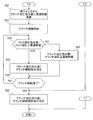
- step S1 it is determined whether or not it is permitted to enter the coast stop control. If YES (CS entry is permitted), the process proceeds to step S2. If NO (CS entry is not permitted), the process proceeds to the end.
- the coast stop control start condition is satisfied, the fuel injection is cut, the rotation speed of the engine 1 is reduced, and then the coast stop control to enter the engine stop state is started.
- step S2 following the determination that the CS entry is permitted in step S1 or the determination that the engine speed is greater than the predetermined value in step S3, it is determined whether or not there is a determination of a departure from the coast stop control. judge. If YES (CS missing determination is present), the process proceeds to step S9. If NO (CS missing determination is not present), the process proceeds to step S3.
- the coast stop control end condition when the coast stop control end condition is satisfied, if the engine speed Ne is equal to or higher than a predetermined speed (for example, 1000 rpm), the engine 1 is performed by fuel injection and ignition without using the starter motor 15. Is restarted (recovered).
- a predetermined speed for example, 1000 rpm
- the engine cranking is performed using the starter motor 15 after the engine speed Ne has sufficiently decreased, and fuel injection is resumed. A starter start for starting the engine 1 is performed.
- step S3 it is determined whether or not the engine speed Ne is equal to or less than a predetermined value (for example, 800 rpm) following the determination in step S2 that there is no CS missing determination. If YES (Ne ⁇ predetermined value), the process proceeds to step S4. If NO (Ne> predetermined value), the process returns to step S2.
- a predetermined value of the engine rotational speed Ne is set to a rotational speed that can be prepared for a restart due to an accelerator depression operation intervention while suppressing occurrence of a shock when the high clutch 33 is released.
- the predetermined value (for example, 800 rpm) of the engine speed Ne is such that the engine 1 recovers at the last rotation speed (for example, 1000 rpm) at which recovery starts, and after the recovery returns, the engine speed Ne is under. Even if the engine is shot and falls below this rotational speed (1000 rpm), the rotational speed (800 rpm) prevents the high clutch 33 from being released even if the engine 1 recovers.
- step S4 following the determination that Ne ⁇ predetermined value in step S3, release of the engaged high clutch 33 is started, and the process proceeds to step S5.
- step S5 following the determination that the high clutch has been released in step S4 or that the high clutch has not been completely released in step S6, whether or not there is a determination of exit from the coast stop control as in step S2. Determine. If YES (CS missing determination is present), the process proceeds to step S9. If NO (CS missing determination is not present), the process proceeds to step S6.
- step S6 it is determined whether or not the complete release of the high clutch 33 has been completed following the determination in step S5 that there is no CS missing determination. If YES (high clutch complete release complete), the process proceeds to step S7. If NO (high clutch complete release incomplete), the process returns to step S5.
- step S7 following the determination that the high clutch complete release has been completed in step S6, CS / IS shift control is executed, and the process proceeds to step S8.
- step S8 following the determination that there is no CS / IS shift control in step S7 or no CS omission determination in step S8, the omission determination from the coast stop control is performed as in steps S2 and S5. It is determined whether or not there is. If YES (CS missing determination is present), the process proceeds to step S9. If NO (CS missing determination is not present), the determination in step S8 is repeated.
- step S9 it is determined whether or not the starter engine is started following the determination that the CS missing determination is present in step S2, step S5, or step S8. If YES (starter engine start), the process proceeds to step S11. If NO (recovery return), the process proceeds to step S10.
- whether the starter engine starts or recovers is determined by the engine speed at the determination timing of the CS missing determination. For example, if the engine speed Ne is maintained at a predetermined speed (1000 rpm) or more when the CS missing is determined, recovery can be recovered by fuel injection and ignition, but the engine speed Ne is set to the predetermined speed (1000 rpm). ), The starter is started using the starter motor 15.
- step S10 following the determination that the recovery is in step S9, it is determined whether or not the high clutch 33 is being engaged. If YES (except when the clutch is engaged), the process proceeds to step S11. If NO (clutch is engaged), the process proceeds to step S26.
- the state other than the clutch being engaged means that the state of the high clutch 33 is completely engaged (the state in which the high clutch 33 is not slipping).
- the primary current instruction value PriSOL / I * of 1A may close the hydraulic circuit to the primary hydraulic chamber 23a against the spring biasing force of the primary solenoid in the absence of the base pressure supplied to the primary solenoid. This is the current indication value that can be generated.
- Step S14 following the setting of the primary current instruction value PriSOL / I * and the change of the clutch hydraulic pressure instruction value PL / B * in Step S13, it is determined whether or not the engine speed Ne is a predetermined value (for example, 500 rpm) or more. Judging. If YES (Ne ⁇ 500 rpm), the process proceeds to step S15. If NO (Ne ⁇ 500 rpm), the determination in step S14 is repeated.
- the predetermined value of the engine rotational speed Ne is set to a rotational speed at which the engine-driven mechanical oil pump 10 can generate a line pressure PL that can be hydraulically controlled to engage the low brake 32.
- step S15 following the determination that Ne ⁇ 500 rpm in step S14 or the determination that the timer value ⁇ predetermined value in step S16, the actual line pressure PL detected by the line pressure sensor 44 is a predetermined value. It is determined whether or not it is a value (for example, 0.5 MPa) or more. If YES (PL ⁇ predetermined value), the process proceeds to step S17. If NO (PL ⁇ predetermined value), the process proceeds to step S16.
- a value for example, 0.5 MPa
- step S16 following the determination that PL ⁇ predetermined value in step S15, the timer value that is started from the time when it is determined that Ne ⁇ 500 rpm and is added as time elapses is greater than or equal to the predetermined value. Determine whether. If YES (timer value ⁇ predetermined value), the process proceeds to step S17. If NO (timer value ⁇ predetermined value), the process returns to step S15.
- step S17 following the determination that PL ⁇ predetermined value in step S15 or the timer value ⁇ predetermined value in step S16, the primary current instruction value PriSOL / I * was output. While releasing 1A (1 ampere), the clutch hydraulic pressure command value PL / B * is changed from the stroke start pressure level command value to the hydraulic pressure command value, and the process proceeds to step S18. By releasing the primary current instruction value PriSOL / I * of 1A (1 ampere), the primary hydraulic cylinder 23a of the primary pulley 21 is supplied with hydraulic pressure based on the target hydraulic pressure.
- Step S18 following the cancellation of the primary current instruction value PriSOL / I * and the change of the clutch oil pressure instruction value PL / B * in Step S17, whether or not the hydraulic charging to the low brake 32 that is engaged at the time of restart is completed. Determine whether. If YES (hydraulic filling is complete), the process proceeds to step S19. If NO (hydraulic filling is not complete), the determination in step S18 is repeated.
- step S19 following the determination that the hydraulic pressure filling is completed in step S18, the target variator ratio fixed in step S7 is cleared, and the process proceeds to step S20.
- step S20 following the target variator ratio fixed clear in step S19, the clutch hydraulic pressure command value upper limit regulation value PL / B * max for the low brake 32 is calculated based on the actual line pressure PL detected by the line pressure sensor 44. Then, the process proceeds to step S21.
- step S21 following the calculation of the clutch hydraulic pressure command value upper limit regulation value PL / B * max in step S20, engagement of the low brake 32, which is the starting clutch, with a clutch engagement command hydraulic pressure described later is started, and the process proceeds to step S22.
- step S22 following the determination that clutch engagement is started in step S21 or clutch engagement is not completed in step S25, the clutch hydraulic pressure instruction value PL / B * to the low brake 32 that is the starting clutch is It is determined whether or not the hydraulic pressure instruction value upper limit regulation value PL / B * max is less. If YES (clutch oil pressure instruction value ⁇ clutch oil pressure instruction value upper limit restriction value), the process proceeds to step S23. If NO (clutch oil pressure instruction value ⁇ clutch oil pressure instruction value upper limit restriction value), the process proceeds to step S24.
- step S23 following the determination that the clutch hydraulic pressure command value ⁇ the clutch hydraulic pressure command value upper limit regulation value in step S22, the clutch hydraulic pressure command value PL / B * is set as the clutch engagement command hydraulic pressure, and the process proceeds to step S25.
- step S24 following the determination in step S22 that the clutch hydraulic pressure command value ⁇ the clutch hydraulic pressure command value upper limit regulation value, the clutch hydraulic pressure command value PL / B * is changed to the clutch hydraulic pressure command value upper limit regulation value PL / B * max. And go to step S25.
- step S25 following the setting of the clutch hydraulic pressure instruction value PL / B * in step S23 or step S24, it is determined whether or not the engagement of the low brake 32, which is the starting clutch, has been completed. If YES (clutch engagement is complete), the process proceeds to step S26. If NO (clutch engagement is not complete), the process returns to step S22.
- step S26 following the determination that the clutch engagement is complete in step S25 or the clutch engagement being performed in step S10, the clutch hydraulic pressure instruction value PL / B * is set as the clutch engagement maintenance instruction hydraulic pressure. Go to the end.
- FIG. 8 shows a time chart based on coast stop compatible transmission control.
- the overall operation of coast stop compatible transmission control will be described with reference to FIGS.
- step S1 When it is permitted to enter the coast stop control and there is no determination of the exit from the coast stop control, in the flowchart of FIG. 5, the process proceeds from step S1 to step S2 to step S3, and in step S3, the engine speed Ne. While the value exceeds the predetermined value, the flow from step S2 to step S3 is repeated. When it is determined in step S3 that the engine speed Ne has become equal to or less than the predetermined value, the process proceeds from step S3 to step S4, and in step S4, the fast clutch 33 that has been engaged is released.
- step S4 If there is no disconnection determination from the coast stop control while the high clutch 33 is disengaged, the process proceeds from step S4 to step S5 to step S6, and until the high clutch 33 completes the complete disengagement, the process proceeds from step S5 to step S6. The forward flow is repeated.
- step S6 If it is determined in step S6 that the complete release of the high clutch 33 has been completed, the process proceeds to step S7.
- step S8 If it is determined in step S8 that there is a CS missing determination in a situation where the engine is stopped due to engine stop, that is, a starter start is performed instead of recovery, the process proceeds from step S9 to step S11 to step S13.
- step S13 the primary current command value PriSOL / I * is set to 1A (1 ampere), and the clutch hydraulic pressure command value PL / B * is changed from 0 MPa to a stroke start pressure level command value.
- step S14 it is determined whether or not the engine speed Ne is a predetermined value or more.
- step S14 When the engine speed Ne becomes greater than or equal to a predetermined value due to starter start, the process proceeds from step S14 to step S15 ⁇ step S17, or from step S14 to step S15 ⁇ step S16 ⁇ step S17.
- step S17 1A (1 ampere) output as the primary current command value PriSOL / I * is released, and the clutch hydraulic pressure command value PL / B * is changed from the stroke start pressure level command value to the hydraulic charge command value. Be changed.
- step S18 it is determined whether or not the hydraulic charging to the low brake 32 that is engaged at the time of restart is completed. When the hydraulic charging to the low brake 32 is completed, the process proceeds to step S19. In S7, the fixed target variator ratio is cleared.
- step S20 the low brake 32 is returned to based on the actual line pressure PL detected by the line pressure sensor 44.
- the clutch hydraulic pressure command value upper limit regulation value PL / B * max is calculated.
- step S21 engagement of the low brake 32, which is a starting clutch, is started. After the engagement of the low brake 32 is started, while the clutch hydraulic pressure command value is smaller than the clutch hydraulic pressure command value upper limit regulation value, the flow of steps S22 ⁇ step S23 ⁇ step S25 is repeated, and in step S23, the clutch hydraulic pressure command value PL / B * is the clutch engagement instruction hydraulic pressure.
- step S24 the clutch hydraulic pressure command value PL / B * is the clutch hydraulic pressure command value upper limit regulation value PL / B * max.
- time t0 is a CS entry permission determination time
- time t1 is a high clutch release start time
- time t2 is a clutch complete release completion time
- time t3 is a vehicle stop time
- time t4 is a CS loss determination time
- Time t5 is a stroke start pressure instruction end time
- time t6 is a filling hydraulic pressure instruction end time.
- Time T1 is a clutch release time
- time T2 is a clutch release maintenance time
- time T3 is a clutch original pressure rising waiting time
- time T4 is a clutch hydraulic pressure filling time
- time T5 is a clutch engagement time.
- the release of the high clutch 33 is started from (point D).
- time t2 complete release of the high clutch 33 is completed.
- the time from time t1 to time t2 is the clutch release time T1.
- the vehicle stop time t3 elapses and the CS release determination time t4 is set as the clutch release maintaining time T2, and the CS / IS shift control is executed.
- the target variator ratio is fixed, and the target slew ratio change amount restriction is invalidated to maintain the lowest gear ratio.
- the lowest speed ratio maintaining time T6 is a time obtained by adding the clutch original pressure rising waiting time T3 and the clutch hydraulic pressure charging time T4 to the clutch disengagement maintaining time T2.
- the starter start of the engine 1 is started, so that the engine speed Ne starts to increase at a time t4 ′ slightly delayed from the time t4.
- the line pressure PL rises based on the discharge pressure from the oil pump 10.
- the clutch original pressure rise waiting time T3 is set, and the clutch hydraulic pressure command value PL / B * is set to the stroke start pressure level command value, and the primary current command value PriSOL / I * is the current skip instruction value (1A).
- the engine speed Ne further increases, and the line pressure PL also rises to the target pressure.
- the clutch oil pressure instruction value PL / B * is set as the oil pressure filling instruction value, and the primary current instruction value PriSOL / I * However, it is diagonally lowered from the current skip command value (1A) to the command value for obtaining the target primary pressure.
- the low brake 32 At the filling hydraulic pressure command end time t6, the low brake 32 actually starts to be engaged, and the clutch hydraulic pressure command value upper limit regulation value PL / B * max is calculated from the actual line pressure PL, and the clutch hydraulic pressure command value upper limit regulation value PL / B * Outputs the clutch hydraulic pressure indication value PL / B * that does not exceed max.
- the engagement of the low brake 32 proceeds, the transmission torque capacity TL / B of the low brake 32 increases, and the vehicle speed VSP also rises accordingly. In other words, the vehicle starts to restart from the timing almost reaching the filling hydraulic pressure instruction end time t6.
- the value PriSOL / I * is output.
- the engine speed Ne in the stopped state gradually increases as the engine 1 is restarted, so that the oil from the mechanical oil pump 10 driven by the engine 1 is also the engine speed.
- the flow rate is gradually increased.
- the pressure regulator valve 111 is in a state where there is no escape path for pump discharge oil
- the pilot valve 112 is in a state where the line pressure oil path 115 and the pilot pressure oil path 116 are communicated by spring force.
- the speed change hydraulic pressure control operation will be described.
- the time T3 from the CS missing determination time t4 to the stroke start pressure command end time t5 is a primary current command value PriSOL / I * for the primary solenoid valve 118, and a current skip command value (1A). ) Is output. Therefore, a solenoid force that overcomes the spring force acts on the valve spool 118d of the primary solenoid valve 118, the operation signal pressure port 118b and the drain port 118c communicate with each other, and the pilot pressure port 118a is closed. That is, oil from the pilot pressure oil passage 116 is prevented from flowing into the primary control valve 119 via the primary solenoid valve 118.
- the valve spool 119d of the primary control valve 119 is not acted on by the operation signal pressure from the primary solenoid valve 118, the primary pressure port 119b and the drain port 119c communicate with each other by the spring force, and the line pressure port 119a is closed. . That is, the oil from the line pressure oil passage 115 is prevented from flowing into the primary hydraulic chamber 23a via the primary control valve 119, and the oil in the primary hydraulic chamber 23a can be discharged via the drain port 119c. Is done.
- the oil from the pilot pressure oil passage 116 is prevented from flowing into the primary solenoid valve 118, and the oil from the line pressure oil passage 115 is supplied to the primary control valve 119. It is blocked from flowing. For this reason, the oil flow rate discharged from the mechanical oil pump 10 by restarting the engine 1 is not consumed on the primary pulley 21 side. Further, the movable conical plate of the primary pulley 21 is acted on by a spring force (not shown) so as to minimize the belt winding diameter, and if extra oil remains in the secondary hydraulic chamber 23a. However, this excess oil is drained quickly. For this reason, the lowest gear ratio is stably maintained as the gear ratio of the variator 20.
- the time T3 from the CS missing determination time t4 to the stroke start pressure command end time t5 is set to the low brake solenoid valve 113 as the clutch hydraulic pressure command value PL / B * and the stroke start.
- the pressure indication value is output.
- the solenoid force acts on the valve spool 113d of the low brake solenoid valve 113, and the pilot pressure port 113a and the low brake pressure port 113b are brought into communication. Therefore, the oil discharged from the mechanical oil pump 10 gradually flows through the line pressure oil passage 115 ⁇ the pilot pressure oil passage 116 ⁇ the low brake pressure oil passage 117 as shown by the dotted arrow in FIG.
- the line to 32 will be filled with oil.
- the oil flow rate from the mechanical oil pump 10 can be used on the low brake 32 side, and the time required until the low brake 32 is engaged is shortened. Further, since the supply of oil to the primary hydraulic chamber 23a is stopped, the variator 20 is held at the lowest speed ratio, and the driving force does not decrease when starting. As a result, it is possible to prevent the start performance from deteriorating when starting from the coast stop control. That is, it is possible to prevent a delay in starting clutch engagement and a decrease in driving force at the start, which is a concern when the electric oil pump is eliminated from the system.
- Example 1 from the coast stop control end time (time t4) to the line pressure generation time (time t5), the primary current instruction value PriSOL / I * that closes the oil path from the mechanical oil pump 10 to the primary pulley 21 in advance .
- the output of the primary current instruction value PriSOL / I * that closes the oil path from the mechanical oil pump 10 to the primary pulley 21 in advance may be continued from the start of the coast stop control. This is because the electric oil pump is abolished so that no oil pressure is generated during coast stop control, and the oil path to the primary pulley 21 can be closed before the engine speed rises due to engine restart. .
- the output duration time of the high primary current instruction value PriSOL / I * to the primary solenoid valve 118 also becomes long, and the output loss to the primary solenoid valve 118 becomes large.
- the output time of the primary current instruction value PriSOL / I * to the primary solenoid valve 118 is from the coast stop control end time (time t4) to the line pressure generation time point (time t4), as shown in the frame of arrow E in FIG.
- the output time is limited to time t5). Therefore, it is possible to suppress the start performance from deteriorating while minimizing the current consumption to the primary solenoid valve 118.
- the vehicle can restart at a time lag (T3 + T4) from the CS missing determination time t4 to the filling hydraulic pressure instruction end time t6.
- the primary current instruction value PriSOL / I * is set to a closed current that can overcome the biasing force of the spring and close the oil path from the mechanical oil pump 10 to the primary pulley 21 regardless of the position of the valve spool 118d. It was set as the value (1A).
- the position of the valve spool 118d of the primary solenoid valve 118 is unclear even if the primary current instruction value PriSOL / I * for zero hydraulic pressure is output at the end of the coast stop control (time t4).
- the urging force acting on the primary solenoid valve 118 by the spring differs depending on the position of the valve spool 118d.
- the oil path from the mechanical oil pump 10 to the primary pulley 21 is overcome by overcoming the spring urging force regardless of the position of the valve spool 118d. Can be securely closed to prevent the hydraulic pressure from being supplied to the primary pulley 21.
- the primary current instruction value PriSOL / I * is gradually increased from the closed circuit current value (1A) to the current value corresponding to the target gear ratio. It was set as the structure reduced. For example, if the primary current instruction value PriSOL / I * is reduced at a stroke when it is determined that the line pressure generation time (time t5) has been reached, the primary solenoid valve 118 suddenly starts pressure adjustment operation, so that the simultaneous progress This affects the hydraulic control for fastening the low brake 32 executed in step S2. On the other hand, by gradually decreasing from the closed circuit current value (1A) to the current value corresponding to the target gear ratio, it is possible to suppress the influence on the hydraulic control for engaging the low brake 32 that is executed simultaneously. .
- the drive system in which the variator 20 is interposed is provided with a sub-transmission mechanism 30 having a plurality of shift stages, and the starting clutch is a forward drive among the frictional engagement elements that change the shift stage of the sub-transmission mechanism 30.
- the low brake 32 is fastened at the first speed.
- Engine 1 and A continuously variable transmission mechanism (variator 20) that is interposed between the engine 1 and the drive wheel 7 and transmits torque by a belt 23 that is pressed against the grooves of the primary pulley 21 and the secondary pulley 22 that are hydraulically driven;
- a starting clutch (low brake 32) provided in a drive system in which the continuously variable transmission mechanism (variator 20) is interposed;
- a mechanical oil pump 10 driven by the engine 1 to supply hydraulic pressure to the primary pulley 21, the secondary pulley 22, and the starting clutch (low brake 32);
- a primary current instruction value PriSOL / I * for closing the oil path from the mechanical oil pump 10 to the primary pulley 21 in advance is output to the primary solenoid valve 118 (FIG. 6). For this reason, it is possible to suppress a decrease in the starting performance when starting from the engine stop control (coast stop control / idle stop control).
- the transmission control means determines the time when the line pressure PL of a predetermined value or more is generated due to the increase in the rotational speed due to the restart of the engine 1 after the end of the engine stop control.
- time t5 a primary current instruction for preliminarily closing the oil path from the mechanical oil pump 10 to the primary pulley 21 from the engine stop control end time (time t4) to the line pressure generation time (time t5).
- the value PriSOL / I * is output to the primary solenoid valve 118. For this reason, in addition to the effect of (1), it is possible to suppress the start performance from deteriorating while minimizing the current consumption to the primary solenoid valve 118.
- the transmission control means overcomes the urging force of the spring from the mechanical oil pump 10 to the primary current instruction value PriSOL / I * regardless of the position of the valve spool 118d.
- a closed circuit current value (1A) that can close the oil path to the primary pulley 21 is used. For this reason, in addition to the effect of (1) or (2), the oil passage from the mechanical oil pump 10 to the primary pulley 21 is reliably closed by overcoming the biasing force of the spring regardless of the position of the valve spool 118d. It is possible to prevent the hydraulic pressure from being supplied to 21.
- a sub-transmission mechanism 30 having a plurality of shift stages is provided in a drive system in which the continuously variable transmission mechanism (variator 20) is interposed;
- the start clutch is a friction engagement element (low brake 32) that is engaged at the first forward speed among the friction engagement elements that change the gear position of the auxiliary transmission mechanism 30.
- Example 1 As mentioned above, although the control apparatus of the continuously variable transmission of this invention was demonstrated based on Example 1, it is not restricted to this Example 1 about a specific structure, It concerns on each claim of a claim Design changes and additions are allowed without departing from the scope of the invention.
- Example 1 shows an example in which both coast stop control and idle stop control are performed as engine stop control.
- the engine stop control may be an example in which only coast stop control is performed, or an example in which only idle stop control is performed.
- Example 1 shows an example in which a continuously variable transmission with a sub-transmission is used as a continuously variable transmission.
- the continuously variable transmission may be an example using a continuously variable transmission that does not have an auxiliary transmission mechanism.
- Example 1 shows an example in which the control device of the present invention is applied to an engine vehicle equipped with a continuously variable transmission with an auxiliary transmission.
- the continuously variable transmission control device of the present invention can also be applied to a hybrid vehicle.
- any vehicle having an engine as a drive source can be applied.
Abstract
Description
この無段変速機の制御装置において、前記メカオイルポンプから前記プライマリプーリへの油路途中位置に設けられ、前記プライマリプーリへの油圧を制御するプライマリソレノイドバルブと、前記プライマリソレノイドバルブへのプライマリ電流指示値を出力する変速機制御手段と、を設ける。
前記変速機制御手段は、前記エンジン停止制御が行われたとき、少なくとも前記エンジンの再始動によりエンジン回転数が立ち上がる前に、前記メカオイルポンプから前記プライマリプーリへの油路を予め閉じておくプライマリ電流指示値を前記プライマリソレノイドバルブに出力する。
したがって、エンジンの再始動によりエンジン回転数が徐々に上昇してゆくと、エンジン回転数が立ち上がる前に、メカオイルポンプからプライマリプーリへの油路を予め閉じられ、プライマリ油圧室へのオイル供給が止められる。
このプライマリ油圧室へのオイル供給が止められることにより、メカオイルポンプからのオイル流量を発進クラッチ側で使うことができ、発進クラッチが締結されるまでに要する時間が短縮される。また、プライマリ油圧室へのオイル供給が止められることにより、無段変速機構が最ロー変速比に保持され、発進時の駆動力低下が発生しない。
この結果、エンジン停止制御から抜ける発進時、発進性能が低下するのを抑制することができる。
実施例1の副変速機付き無段変速機(無段変速機の一例)の制御装置を、「全体システム構成」、「変速マップによる変速制御構成」、「コーストストップ制御構成」、「コーストストップ対応変速機制御構成」に分けて説明する。
図1は、実施例1の制御装置が適用された副変速機付き無段変速機が搭載された車両の概略構成を示し、図2は、変速機コントローラの内部構成を示す。以下、図1及び図2に基づき、全体システム構成を説明する。
なお、以下の説明において、ある変速機構の「変速比」は、当該変速機構の入力回転速度を当該変速機構の出力回転速度で割って得られる値である。また、「最ロー変速比」は当該変速機構の最大変速比を意味し、「最ハイ変速比」は当該変速機構の最小変速比を意味する。
また、車両には、エンジン1の動力により駆動されるメカオイルポンプ10と、メカオイルポンプ10からの吐出圧を調圧して変速機4の各部位に供給する油圧制御回路11と、油圧制御回路11を制御する変速機コントローラ12と、統合コントローラ13と、エンジンコントローラ14と、が設けられている。以下、各構成について説明する。
図3は、変速機コントローラ12の記憶装置122に格納される変速マップの一例を示す。以下、図3に基づき、変速マップによる変速制御構成を説明する。
この変速マップには、従来のベルト式無段変速機の変速マップと同様に、アクセル開度APO毎に変速線が設定されており、変速機4の変速はアクセル開度APOに応じて選択される変速線に従って行われる。なお、図3には簡単のため、全負荷線F/L(アクセル開度APO=8/8のときの変速線)、パーシャル線P/L(アクセル開度APO=4/8のときの変速線)、コースト線C/L(アクセル開度APO=0のときの変速線)のみが示されている。
実施例1のエンジンコントローラ14は、燃料消費量をできる限り抑制するために、車両停止中にエンジン1を停止する「アイドルストップ制御」に加えて、車両のコースト走行中(惰性走行中)からエンジン1を停止する「コーストストップ制御」を行う。
(a):アクセルペダルから足が離されている(アクセル開度APO=0)
(b):ブレーキペダルが踏み込まれている(図示しないブレーキセンサがON)
(c):車速VSPが所定の低車速(例えば、15km/h)以下
(d):ロックアップクラッチ9が解放(例えば、車速13km/h)されている
(e):ハイクラッチ33の締結による高速モード(2速)が選択されている
なお、これらの条件(a)~(e)は、言い換えると運転者に停車意図があることを判断する条件である。
図5~図7は、実施例1の変速機コントローラ12にて実行されるコーストストップ対応変速機制御処理流れを示す(変速機制御手段)。以下、コーストストップ対応変速機制御処理構成をあらわす図5~図7の各ステップについて説明する。なお、コーストストップ制御の略称を「CS」といい、アイドルストップ制御の略称を「IS」という。
ここで、CS入り許可の判断は、コーストストップ制御中フラグが、フラグ=0(CS非制御)からフラグ=1(CS制御中)に切り替わったことで行う。なお、エンジン制御側では、コーストストップ制御開始条件が成立すると、燃料噴射をカットし、エンジン1の回転数を低下させた後、エンジン停止状態とするコーストストップ制御の実行が開始される。
ここで、CS抜け判定有りの判断は、コーストストップ制御中フラグが、フラグ=1(CS制御中)からフラグ=0(CS非制御)に切り替わったことで行う。なお、エンジン制御側では、コーストストップ制御終了条件が成立した場合、エンジン回転数Neが所定回転数(例えば、1000rpm)以上であれば、スタータモータ15を用いることなく、燃料噴射と点火によりエンジン1を再始動(リカバ復帰)させる。エンジン回転数Neが所定回転数(例えば、1000rpm)より低くリカバ復帰できない場合、エンジン回転数Neが十分に低下してから、スタータモータ15を用いてエンジンクランキングを行い、燃料噴射を再開してエンジン1を始動させるスタータ始動が行われる。
ここで、エンジン回転数Neの所定値は、ハイクラッチ33を解放したときにショックの発生を抑えつつ、アクセル踏み込み操作介入による再始動に備えることができる回転数に設定される。また、このエンジン回転数Neの所定値(例えば、800rpm)は、エンジン1がリカバ復帰を開始するギリギリの回転数(例えば、1000rpm)でリカバ復帰して、リカバ復帰後に、エンジン回転数Neがアンダーシュートして、この回転数(1000rpm)を下回っても、エンジン1がリカバ復帰したにもかかわらず、ハイクラッチ33を解放しないようにする回転数(800rpm)でもある。
ここで、CS/IS時変速制御では、
(a) 目標バリエータレシオ固定
(b) 目標スルーレシオ変化量制限無効化
(c) 副変速ギア位置2速→1速
(d) プライマリ電流指示値=CS/IS中指示電流値
による制御が行われる。
ここで、スタータエンジン始動であるかリカバ復帰であるかは、CS抜け判定有りの判断タイミングでのエンジン回転数で決まる。例えば、CS抜け判定があった時に、所定回転数(1000rpm)以上のエンジン回転数Neが保たれている場合は、燃料噴射と点火によりリカバ復帰できるが、エンジン回転数Neが所定回転数(1000rpm)未満まで低下すると、スタータモータ15を用いたスタータ始動となる。
ここで、クラッチ締結中以外とは、ハイクラッチ33の状態が完全締結状態(ハイクラッチ33が滑っていない状態)をいう。
ここで、1Aというプライマリ電流指示値PriSOL/I*は、プライマリソレノイドへ供給される基圧がない状態において、プライマリソレノイドのバネ付勢力に抗してプライマリ油圧室23aへの油圧回路を閉じることができる電流指示値である。
ここで、エンジン回転数Neの所定値は、エンジン駆動のメカオイルポンプ10が、ローブレーキ32を締結する油圧制御が可能なライン圧PLを発生することができる回転数に設定される。
ここで、クラッチ油圧指示値上限規制値PL/B*maxは、バリエータ20のベルト容量Tを、実ライン圧PLに基づき算出し、このベルト容量算出値T(PL)から所定のマージン分αを差し引いた、
PL/B*max=T(PL)-α
の式により演算される。
ここで、クラッチ締結指示油圧は、
クラッチ締結指示油圧=τNe2×t×ギア比+(回転低下に必要なトルク)
の式にて求められる。
なお、“τ”はトルク容量係数であり、“t”はトルク比であり、“τNe2×t”はタービントルクをあらわす。“ギア比”はリダクションギア比であり、“回転低下に必要なトルク”は、バリエータ20のイナーシャトルクに相当する。
実施例1の副変速機付き無段変速機の制御装置における作用を、「コーストストップ対応変速機制御の全体作用」、「コーストストップ制御から抜けるときの油圧制御作用」、「コーストストップ制御からの発進制御作用」に分けて説明する。
図8は、コーストストップ対応変速機制御によるタイムチャートを示す。以下、図5~図8に基づき、コーストストップ対応変速機制御の全体作用を説明する。
(a) 目標バリエータレシオ固定
(b) 目標スルーレシオ変化量制限無効化
(c) 副変速ギア位置2速→1速
(d) プライマリ電流指示値=CS/IS中指示電流値
によるCS/IS時変速制御が実行される。このCS/IS時変速制御は、ステップS8にてCS抜け判定有りと判断されるまで継続して実行される。
上記のように、プライマリソレノイドバルブ118へは、CS抜け判定時刻t4からストローク開始圧指示終了時刻t5までの間(=クラッチ元圧立ち上がり待ち時間T3)、電流飛ばし指示値(1A)によるプライマリ電流指示値PriSOL/I*が出力される。
上記のように、実施例1では、コーストストップ制御が行われたとき、少なくともエンジン1の再始動によりエンジン回転数Neが立ち上がる前に、メカオイルポンプ10からプライマリプーリ21への油路を予め閉じておくプライマリ電流指示値PriSOL/I*を、プライマリソレノイドバルブ118に出力する構成とした。
したがって、エンジン1の再始動によりエンジン回転数Neが徐々に上昇してゆくと、エンジン回転数Neが立ち上がる前に、メカオイルポンプ10からプライマリプーリ21への油路を予め閉じられ、プライマリ油圧室23aへのオイル供給が止められる。
このプライマリ油圧室23aへのオイル供給が止められることにより、メカオイルポンプ10からのオイル流量をローブレーキ32側で使うことができ、ローブレーキ32が締結されるまでに要する時間が短縮される。また、プライマリ油圧室23aへのオイル供給が止められることにより、バリエータ20が最ロー変速比に保持され、発進時の駆動力低下が発生しない。
この結果、コーストストップ制御から抜ける発進時、発進性能が低下するのを抑制することができる。すなわち、電動オイルポンプを廃止したシステムとしたときに懸念される発進クラッチの締結遅れや発進時の駆動力低下を防止できる。
例えば、メカオイルポンプ10からプライマリプーリ21への油路を予め閉じておくプライマリ電流指示値PriSOL/I*の出力は、コーストストップ制御開始時点から継続しても良い。なぜなら、電動オイルポンプが廃止されていることで、コーストストップ制御中は油圧の発生が無く、エンジン再始動によりエンジン回転数が立ち上がる前にプライマリプーリ21への油路を閉じることができるからである。
しかし、この場合、停車時間が長いと、プライマリソレノイドバルブ118への高いプライマリ電流指示値PriSOL/I*の出力継続時間も長くなり、プライマリソレノイドバルブ118への出力損失が大きくなる。
これに対し、プライマリソレノイドバルブ118に対するプライマリ電流指示値PriSOL/I*の出力時間が、図8の矢印Eの枠内に示すように、コーストストップ制御終了時点(時刻t4)からライン圧生成時点(時刻t5)までの限られた出力時間とされる。
したがって、プライマリソレノイドバルブ118への電流消費量を最小限に抑えながら、発進性能が低下するのを抑制することができる。ちなみに、実施例1の場合、図8の矢印Fの枠内に示すように、CS抜け判定時刻t4から充填油圧指示終了時刻t6までのタイムラグ(T3+T4)で再発進することができる。
例えば、コーストストップ制御終了時点(時刻t4)で油圧ゼロとするプライマリ電流指示値PriSOL/I*を出力してもプライマリソレノイドバルブ118のバルブスプール118dの位置は不明である。これに対し、プライマリソレノイドバルブ118は、バルブスプール118dの位置によってバネによって作用する付勢力が異なる。
したがって、プライマリ電流指示値PriSOL/I*を閉路電流値(1A)とすることで、バルブスプール118dの位置にかかわらず、バネの付勢力に打ち勝ってメカオイルポンプ10からプライマリプーリ21への油路を確実に閉じ、プライマリプーリ21に油圧が供給されるのを防止することができる。
例えば、ライン圧生成時点(時刻t5)に到達したと判断された時点でプライマリ電流指示値PriSOL/I*を一気に低下させると、プライマリソレノイドバルブ118が急に調圧動作を開始するため、同時進行で実行されているローブレーキ32を締結する油圧制御に影響を与える。
これに対し、閉路電流値(1A)から目標変速比に応じた電流値まで徐々に低下させることで、同時進行で実行されているローブレーキ32を締結する油圧制御への影響を抑えることができる。
この構成により、電動オイルポンプを廃止した副変速機付き無段変速機を搭載した車両において、エンジン停止制御(コーストストップ制御/アイドルストップ制御)の終了後、応答遅れのない発進性能を確保することができる。
実施例1の副変速機付き無段変速機の制御装置にあっては、下記に列挙する効果を得ることができる。
前記エンジン1と駆動輪7との間に介装され、油圧駆動のプライマリプーリ21とセカンダリプーリ22の溝に押圧されるベルト23によりトルクを伝達する無段変速機構(バリエータ20)と、
前記無段変速機構(バリエータ20)が介装された駆動系に設けられた発進クラッチ(ローブレーキ32)と、
前記エンジン1により駆動され、前記プライマリプーリ21と前記セカンダリプーリ22と前記発進クラッチ(ローブレーキ32)への油圧を供給するメカオイルポンプ10と、
所定の開始条件が成立すると前記エンジン1を停止し、所定の終了条件が成立するとエンジン停止制御(コーストストップ制御/アイドルストップ制御)を終了し、前記エンジン1を再始動するエンジン停止制御手段(エンジンコントローラ14)と、
を備えた無段変速機(副変速機付き無段変速機)の制御装置において、
前記メカオイルポンプ10から前記プライマリプーリ21への油路途中位置に設けられ、前記プライマリプーリ21への油圧を制御するプライマリソレノイドバルブ118と、
前記プライマリソレノイドバルブ118へのプライマリ電流指示値PriSOL/I*を出力する変速機制御手段(変速機コントローラ12)と、を設け、
前記変速機制御手段(変速機コントローラ12)は、前記エンジン停止制御(コーストストップ制御/アイドルストップ制御)が行われたとき、少なくとも前記エンジン1の再始動によりエンジン回転数Neが立ち上がる前に、前記メカオイルポンプ10から前記プライマリプーリ21への油路を予め閉じておくプライマリ電流指示値PriSOL/I*を前記プライマリソレノイドバルブ118に出力する(図6)。
このため、エンジン停止制御(コーストストップ制御/アイドルストップ制御)から抜ける発進時、発進性能が低下するのを抑制することができる。
このため、(1)の効果に加え、プライマリソレノイドバルブ118への電流消費量を最小限に抑えながら、発進性能が低下するのを抑制することができる。
このため、(1)又は(2)の効果に加え、バルブスプール118dの位置にかかわらず、バネの付勢力に打ち勝ってメカオイルポンプ10からプライマリプーリ21への油路を確実に閉じ、プライマリプーリ21に油圧が供給されるのを防止することができる。
このため、(3)の効果に加え、同時進行で実行されているローブレーキ32を締結する油圧制御への影響を抑えることができる。
前記発進クラッチは、前記副変速機構30の変速段を変更する摩擦締結要素のうち、前進1速にて締結される摩擦締結要素(ローブレーキ32)である。
このため、(1)~(4)の効果に加え、電動オイルポンプを廃止した副変速機付き無段変速機を搭載した車両において、エンジン停止制御(コーストストップ制御/アイドルストップ制御)の終了後、応答遅れのない発進性能を確保することができる。
Claims (5)
- エンジンと、
前記エンジンと駆動輪との間に介装され、油圧駆動のプライマリプーリとセカンダリプーリの溝に押圧されるベルトによりトルクを伝達する無段変速機構と、
前記無段変速機構が介装された駆動系に設けられた発進クラッチと、
前記エンジンにより駆動され、前記プライマリプーリと前記セカンダリプーリと前記発進クラッチへの油圧を供給するメカオイルポンプと、
所定の開始条件が成立すると前記エンジンを停止し、所定の終了条件が成立するとエンジン停止制御を終了し、前記エンジンを再始動するエンジン停止制御手段と、
を備えた無段変速機の制御装置において、
前記メカオイルポンプから前記プライマリプーリへの油路途中位置に設けられ、前記プライマリプーリへの油圧を制御するプライマリソレノイドバルブと、
前記プライマリソレノイドバルブへのプライマリ電流指示値を出力する変速機制御手段と、を設け、
前記変速機制御手段は、前記エンジン停止制御が行われたとき、少なくとも前記エンジンの再始動によりエンジン回転数が立ち上がる前に、前記メカオイルポンプから前記プライマリプーリへの油路を予め閉じておくプライマリ電流指示値を前記プライマリソレノイドバルブに出力する、無段変速機の制御装置。 - 請求項1に記載された無段変速機の制御装置において、
前記変速機制御手段は、エンジン停止制御終了後に前記エンジンの再始動による回転数上昇により、所定値以上のライン圧が生成される時点をライン圧生成時点というとき、エンジン停止制御終了時点から前記ライン圧生成時点まで、前記メカオイルポンプから前記プライマリプーリへの油路を予め閉じておくプライマリ電流指示値を前記プライマリソレノイドバルブに出力する、無段変速機の制御装置。 - 請求項1又は2に記載された無段変速機の制御装置において、
前記変速機制御手段は、前記プライマリ電流指示値を、バルブスプールの位置にかかわらず、バネの付勢力に打ち勝って前記メカオイルポンプから前記プライマリプーリへの油路を閉じることができる閉路電流値とする、無段変速機の制御装置。 - 請求項3に記載された無段変速機の制御装置において、
前記変速機制御手段は、前記ライン圧生成時点に到達したと判断されると、前記プライマリ電流指示値を、前記閉路電流値から目標変速比に応じた電流値まで徐々に低下させる、無段変速機の制御装置。 - 請求項1から4までの何れか一項に記載された無段変速機の制御装置において、
前記無段変速機構が介装された駆動系に、複数の変速段を有する副変速機構を設け、
前記発進クラッチは、前記副変速機構の変速段を変更する摩擦締結要素のうち、前進1速にて締結されるローブレーキである、無段変速機の制御装置。
Priority Applications (5)
| Application Number | Priority Date | Filing Date | Title |
|---|---|---|---|
| KR1020167015165A KR101796408B1 (ko) | 2013-12-11 | 2014-12-10 | 무단 변속기의 제어 장치 |
| EP14869020.9A EP3081832A4 (en) | 2013-12-11 | 2014-12-10 | Control device for continuously variable transmission |
| US15/036,140 US9945478B2 (en) | 2013-12-11 | 2014-12-10 | Control device for continuously variable transmission |
| JP2015552475A JP6106287B2 (ja) | 2013-12-11 | 2014-12-10 | 無段変速機の制御装置 |
| CN201480067259.6A CN105814342B (zh) | 2013-12-11 | 2014-12-10 | 无级变速器的控制装置 |
Applications Claiming Priority (2)
| Application Number | Priority Date | Filing Date | Title |
|---|---|---|---|
| JP2013256399 | 2013-12-11 | ||
| JP2013-256399 | 2013-12-11 |
Publications (1)
| Publication Number | Publication Date |
|---|---|
| WO2015087900A1 true WO2015087900A1 (ja) | 2015-06-18 |
Family
ID=53371202
Family Applications (1)
| Application Number | Title | Priority Date | Filing Date |
|---|---|---|---|
| PCT/JP2014/082641 WO2015087900A1 (ja) | 2013-12-11 | 2014-12-10 | 無段変速機の制御装置 |
Country Status (6)
| Country | Link |
|---|---|
| US (1) | US9945478B2 (ja) |
| EP (1) | EP3081832A4 (ja) |
| JP (1) | JP6106287B2 (ja) |
| KR (1) | KR101796408B1 (ja) |
| CN (1) | CN105814342B (ja) |
| WO (1) | WO2015087900A1 (ja) |
Cited By (1)
| Publication number | Priority date | Publication date | Assignee | Title |
|---|---|---|---|---|
| BE1023743B1 (nl) * | 2016-06-07 | 2017-07-07 | Punch Powertrain Nv | Continu variabele transmissiesysteem |
Families Citing this family (8)
| Publication number | Priority date | Publication date | Assignee | Title |
|---|---|---|---|---|
| WO2015114603A2 (en) * | 2014-01-31 | 2015-08-06 | Brp-Powertrain Gmbh & Co. Kg | Continuously variable transmission and vehicle control methods |
| JP6518177B2 (ja) * | 2015-10-02 | 2019-05-22 | ジヤトコ株式会社 | 車両の制御装置及び車両の制御方法 |
| WO2018070292A1 (ja) * | 2016-10-11 | 2018-04-19 | ジヤトコ株式会社 | 自動変速機のプーリ推進装置および自動変速機の制御装置 |
| EP3546800B1 (en) * | 2016-11-24 | 2021-05-19 | Nissan Motor Co., Ltd. | Continuously variable transmission and method for controlling continuously variable transmission |
| JP2019031153A (ja) * | 2017-08-07 | 2019-02-28 | いすゞ自動車株式会社 | 走行制御装置、車両および走行制御方法 |
| JP2021063534A (ja) * | 2019-10-11 | 2021-04-22 | 本田技研工業株式会社 | 無段変速機の油圧制御装置 |
| JP7241003B2 (ja) * | 2019-11-18 | 2023-03-16 | 本田技研工業株式会社 | 無段変速機の制御装置 |
| JP7412590B2 (ja) * | 2020-11-02 | 2024-01-12 | ジヤトコ株式会社 | プーリ圧制御弁のダンピング圧供給回路 |
Citations (5)
| Publication number | Priority date | Publication date | Assignee | Title |
|---|---|---|---|---|
| JPH01120429U (ja) * | 1988-02-09 | 1989-08-15 | ||
| JP2010230131A (ja) * | 2009-03-27 | 2010-10-14 | Daihatsu Motor Co Ltd | 車両の制御装置 |
| JP2011214699A (ja) * | 2010-04-01 | 2011-10-27 | Toyota Motor Corp | ベルト式無段変速機の油圧制御装置 |
| JP2012077840A (ja) | 2010-10-01 | 2012-04-19 | Jatco Ltd | コーストストップ車両 |
| JP2013204722A (ja) | 2012-03-28 | 2013-10-07 | Jatco Ltd | ベルト式無段変速機の変速制御装置 |
Family Cites Families (11)
| Publication number | Priority date | Publication date | Assignee | Title |
|---|---|---|---|---|
| EP1070868B1 (en) * | 1999-07-21 | 2004-04-28 | Honda Giken Kogyo Kabushiki Kaisha | Apparatus for controlling starting clutch of vehicle having function of stopping engine idling |
| JP3653028B2 (ja) * | 2001-10-17 | 2005-05-25 | 本田技研工業株式会社 | 車両用動力伝達制御装置 |
| JP4358130B2 (ja) * | 2005-02-22 | 2009-11-04 | ジヤトコ株式会社 | 自動変速機の油圧制御装置 |
| JP4573796B2 (ja) | 2006-03-31 | 2010-11-04 | ジヤトコ株式会社 | 自動変速機の油圧制御装置 |
| JP2009133428A (ja) * | 2007-11-30 | 2009-06-18 | Aisin Aw Co Ltd | 車両用駆動装置 |
| KR100992789B1 (ko) | 2008-11-17 | 2010-11-05 | 현대자동차주식회사 | 하이브리드 차량의 무단변속기 유압제어장치 |
| CN102159842A (zh) * | 2008-12-25 | 2011-08-17 | 爱信艾达株式会社 | 车辆用驱动装置 |
| JP5527873B2 (ja) * | 2009-03-18 | 2014-06-25 | 株式会社エフ・シー・シー | 動力伝達装置 |
| JP2012007784A (ja) | 2010-06-23 | 2012-01-12 | Sanyo Electric Co Ltd | 吸収冷温水機及びその運転制御方法 |
| JP5380402B2 (ja) * | 2010-09-10 | 2014-01-08 | ジヤトコ株式会社 | 自動変速機及び油圧制御装置 |
| JP5693507B2 (ja) | 2012-03-28 | 2015-04-01 | ジヤトコ株式会社 | 自動変速機の油圧制御装置 |
-
2014
- 2014-12-10 KR KR1020167015165A patent/KR101796408B1/ko active IP Right Grant
- 2014-12-10 US US15/036,140 patent/US9945478B2/en active Active
- 2014-12-10 EP EP14869020.9A patent/EP3081832A4/en not_active Withdrawn
- 2014-12-10 JP JP2015552475A patent/JP6106287B2/ja active Active
- 2014-12-10 CN CN201480067259.6A patent/CN105814342B/zh active Active
- 2014-12-10 WO PCT/JP2014/082641 patent/WO2015087900A1/ja active Application Filing
Patent Citations (5)
| Publication number | Priority date | Publication date | Assignee | Title |
|---|---|---|---|---|
| JPH01120429U (ja) * | 1988-02-09 | 1989-08-15 | ||
| JP2010230131A (ja) * | 2009-03-27 | 2010-10-14 | Daihatsu Motor Co Ltd | 車両の制御装置 |
| JP2011214699A (ja) * | 2010-04-01 | 2011-10-27 | Toyota Motor Corp | ベルト式無段変速機の油圧制御装置 |
| JP2012077840A (ja) | 2010-10-01 | 2012-04-19 | Jatco Ltd | コーストストップ車両 |
| JP2013204722A (ja) | 2012-03-28 | 2013-10-07 | Jatco Ltd | ベルト式無段変速機の変速制御装置 |
Non-Patent Citations (1)
| Title |
|---|
| See also references of EP3081832A4 * |
Cited By (2)
| Publication number | Priority date | Publication date | Assignee | Title |
|---|---|---|---|---|
| BE1023743B1 (nl) * | 2016-06-07 | 2017-07-07 | Punch Powertrain Nv | Continu variabele transmissiesysteem |
| WO2017211808A1 (en) * | 2016-06-07 | 2017-12-14 | Punch Powertrain N.V. | Continuously variable transmission system |
Also Published As
| Publication number | Publication date |
|---|---|
| CN105814342B (zh) | 2017-10-13 |
| CN105814342A (zh) | 2016-07-27 |
| EP3081832A4 (en) | 2017-11-08 |
| US9945478B2 (en) | 2018-04-17 |
| US20160290503A1 (en) | 2016-10-06 |
| KR101796408B1 (ko) | 2017-11-09 |
| EP3081832A1 (en) | 2016-10-19 |
| JPWO2015087900A1 (ja) | 2017-03-16 |
| KR20160082702A (ko) | 2016-07-08 |
| JP6106287B2 (ja) | 2017-03-29 |
Similar Documents
| Publication | Publication Date | Title |
|---|---|---|
| JP6106287B2 (ja) | 無段変速機の制御装置 | |
| KR101331349B1 (ko) | 코스트 스톱 차량 및 코스트 스톱 차량의 제어 방법 | |
| US8585550B2 (en) | Coast stop vehicle and control method for coast stop vehicle | |
| US8696515B2 (en) | Coast stop vehicle and control method thereof | |
| JP5728422B2 (ja) | ベルト式無段変速機の変速制御装置 | |
| JP5542607B2 (ja) | コーストストップ車両及びコーストストップ方法 | |
| US20130260929A1 (en) | Control device and control method for continuously variable transmission | |
| US9022901B2 (en) | Coast stop vehicle and control method thereof | |
| JP6053666B2 (ja) | 無段変速機の制御装置 | |
| KR102054087B1 (ko) | 차량의 세일링 스톱 제어 방법 및 제어 장치 | |
| JP5718530B2 (ja) | 車両用の自動変速機 | |
| JP5948623B2 (ja) | 無段変速機の制御装置 | |
| JP6084155B2 (ja) | 車両用変速機の制御装置 | |
| JP6084154B2 (ja) | 車両用変速機の制御装置 | |
| JP5860150B2 (ja) | 車両用の自動変速機 | |
| JP6242835B2 (ja) | 自動変速機の制御装置 | |
| JP6124828B2 (ja) | 車両用変速機の制御装置 | |
| JP6598712B2 (ja) | 車両のセーリングストップ制御方法及び制御装置 | |
| JP6752506B2 (ja) | 車両用無段変速機構の制御装置 |
Legal Events
| Date | Code | Title | Description |
|---|---|---|---|
| 121 | Ep: the epo has been informed by wipo that ep was designated in this application |
Ref document number: 14869020 Country of ref document: EP Kind code of ref document: A1 |
|
| DPE2 | Request for preliminary examination filed before expiration of 19th month from priority date (pct application filed from 20040101) | ||
| ENP | Entry into the national phase |
Ref document number: 2015552475 Country of ref document: JP Kind code of ref document: A |
|
| WWE | Wipo information: entry into national phase |
Ref document number: 15036140 Country of ref document: US |
|
| ENP | Entry into the national phase |
Ref document number: 20167015165 Country of ref document: KR Kind code of ref document: A |
|
| NENP | Non-entry into the national phase |
Ref country code: DE |
|
| REEP | Request for entry into the european phase |
Ref document number: 2014869020 Country of ref document: EP |
|
| WWE | Wipo information: entry into national phase |
Ref document number: 2014869020 Country of ref document: EP |