WO2015079997A1 - 燃料供給装置 - Google Patents
燃料供給装置 Download PDFInfo
- Publication number
- WO2015079997A1 WO2015079997A1 PCT/JP2014/080650 JP2014080650W WO2015079997A1 WO 2015079997 A1 WO2015079997 A1 WO 2015079997A1 JP 2014080650 W JP2014080650 W JP 2014080650W WO 2015079997 A1 WO2015079997 A1 WO 2015079997A1
- Authority
- WO
- WIPO (PCT)
- Prior art keywords
- energization
- valve
- fuel supply
- shutoff valve
- fuel
- Prior art date
- Legal status (The legal status is an assumption and is not a legal conclusion. Google has not performed a legal analysis and makes no representation as to the accuracy of the status listed.)
- Ceased
Links
Images


Classifications
-
- F—MECHANICAL ENGINEERING; LIGHTING; HEATING; WEAPONS; BLASTING
- F02—COMBUSTION ENGINES; HOT-GAS OR COMBUSTION-PRODUCT ENGINE PLANTS
- F02D—CONTROLLING COMBUSTION ENGINES
- F02D19/00—Controlling engines characterised by their use of non-liquid fuels, pluralities of fuels, or non-fuel substances added to the combustible mixtures
- F02D19/06—Controlling engines characterised by their use of non-liquid fuels, pluralities of fuels, or non-fuel substances added to the combustible mixtures peculiar to engines working with pluralities of fuels, e.g. alternatively with light and heavy fuel oil, other than engines indifferent to the fuel consumed
- F02D19/0663—Details on the fuel supply system, e.g. tanks, valves, pipes, pumps, rails, injectors or mixers
- F02D19/0673—Valves; Pressure or flow regulators; Mixers
- F02D19/0681—Shut-off valves; Check valves; Safety valves; Pressure relief valves
-
- F—MECHANICAL ENGINEERING; LIGHTING; HEATING; WEAPONS; BLASTING
- F02—COMBUSTION ENGINES; HOT-GAS OR COMBUSTION-PRODUCT ENGINE PLANTS
- F02D—CONTROLLING COMBUSTION ENGINES
- F02D19/00—Controlling engines characterised by their use of non-liquid fuels, pluralities of fuels, or non-fuel substances added to the combustible mixtures
- F02D19/06—Controlling engines characterised by their use of non-liquid fuels, pluralities of fuels, or non-fuel substances added to the combustible mixtures peculiar to engines working with pluralities of fuels, e.g. alternatively with light and heavy fuel oil, other than engines indifferent to the fuel consumed
- F02D19/0663—Details on the fuel supply system, e.g. tanks, valves, pipes, pumps, rails, injectors or mixers
-
- F—MECHANICAL ENGINEERING; LIGHTING; HEATING; WEAPONS; BLASTING
- F02—COMBUSTION ENGINES; HOT-GAS OR COMBUSTION-PRODUCT ENGINE PLANTS
- F02D—CONTROLLING COMBUSTION ENGINES
- F02D19/00—Controlling engines characterised by their use of non-liquid fuels, pluralities of fuels, or non-fuel substances added to the combustible mixtures
- F02D19/06—Controlling engines characterised by their use of non-liquid fuels, pluralities of fuels, or non-fuel substances added to the combustible mixtures peculiar to engines working with pluralities of fuels, e.g. alternatively with light and heavy fuel oil, other than engines indifferent to the fuel consumed
- F02D19/0639—Controlling engines characterised by their use of non-liquid fuels, pluralities of fuels, or non-fuel substances added to the combustible mixtures peculiar to engines working with pluralities of fuels, e.g. alternatively with light and heavy fuel oil, other than engines indifferent to the fuel consumed characterised by the type of fuels
- F02D19/0642—Controlling engines characterised by their use of non-liquid fuels, pluralities of fuels, or non-fuel substances added to the combustible mixtures peculiar to engines working with pluralities of fuels, e.g. alternatively with light and heavy fuel oil, other than engines indifferent to the fuel consumed characterised by the type of fuels at least one fuel being gaseous, the other fuels being gaseous or liquid at standard conditions
- F02D19/0647—Controlling engines characterised by their use of non-liquid fuels, pluralities of fuels, or non-fuel substances added to the combustible mixtures peculiar to engines working with pluralities of fuels, e.g. alternatively with light and heavy fuel oil, other than engines indifferent to the fuel consumed characterised by the type of fuels at least one fuel being gaseous, the other fuels being gaseous or liquid at standard conditions the gaseous fuel being liquefied petroleum gas [LPG], liquefied natural gas [LNG], compressed natural gas [CNG] or dimethyl ether [DME]
-
- Y—GENERAL TAGGING OF NEW TECHNOLOGICAL DEVELOPMENTS; GENERAL TAGGING OF CROSS-SECTIONAL TECHNOLOGIES SPANNING OVER SEVERAL SECTIONS OF THE IPC; TECHNICAL SUBJECTS COVERED BY FORMER USPC CROSS-REFERENCE ART COLLECTIONS [XRACs] AND DIGESTS
- Y02—TECHNOLOGIES OR APPLICATIONS FOR MITIGATION OR ADAPTATION AGAINST CLIMATE CHANGE
- Y02T—CLIMATE CHANGE MITIGATION TECHNOLOGIES RELATED TO TRANSPORTATION
- Y02T10/00—Road transport of goods or passengers
- Y02T10/10—Internal combustion engine [ICE] based vehicles
- Y02T10/30—Use of alternative fuels, e.g. biofuels
Definitions
- This invention relates to a fuel supply device provided with an electric shut-off valve.
- Patent Document 1 discloses a fuel supply device in which an electric shut-off valve is provided in a fuel supply passage.
- the fuel supply device of Patent Document 1 is configured to increase the driving force of the shut-off valve by passing a large current through the shut-off valve in order to open the shut-off valve fixed with fuel. However, if a large current continues to flow through the shut-off valve, the shut-off valve temperature rises and the shut-off valve is damaged.
- the ECU of the fuel supply device calculates and stores the time from when the shutoff valve is closed to when the internal combustion engine stops when the internal combustion engine stops. Further, the ECU detects the temperature of the engine cooling water and the fuel pressure when starting the internal combustion engine. Further, the ECU calculates the time for opening the shutoff valve by flowing a large current based on the time taken for the internal combustion engine to stop and the temperature and pressure detected at the start. Then, the ECU drives the shutoff valve by flowing a large current until the calculated time elapses.
- the ignition switch may be repeatedly turned on and off.
- the energization period to the shutoff valve based on each valve open command is not long, a large current is repeatedly passed through the shutoff valve by repeating the valve open command to the shutoff valve.
- the temperature of the shutoff valve rises and the shutoff valve may be damaged.
- An object of the present invention is to provide a fuel supply device capable of suppressing damage to a shut-off valve even when a valve opening command is repeated.
- a fuel tank for supplying fuel stored in the fuel tank, and an electric motor that is disposed in the fuel supply passage and opens when energized.
- a control unit that controls energization of the shut-off valve, and a fuel supply device that opens the shut-off valve by energizing an open drive current larger than a holding current at which the control unit maintains the open state.
- the control unit executes processing for prohibiting energization of the shutoff valve based on the energization history of the open drive current to the shutoff valve within the retroactive period.
- energization of the shut-off valve is prohibited with reference to the energization history of a plurality of open drive currents within the retroactive period as well as the energization period of one open drive current. Therefore, it is possible to prohibit energization of the shutoff valve based on the energization history indicating that the open drive current larger than the holding current is energized repeatedly. Therefore, even if the valve opening command is repeatedly output, damage to the shutoff valve can be suppressed.
- control unit starts a process of prohibiting energization of the shutoff valve on condition that the integrated value of the open drive current energization time within the retroactive period is equal to or greater than the upper limit value.
- the temperature of the shutoff valve rises greatly.
- the open drive current is not energized, the temperature of the shutoff valve is unlikely to rise. Therefore, by referring to the integrated value of the open drive current energization time within the retroactive period, the ratio of the period during which the shut-off valve temperature has greatly increased during the retroactive period and the period during which the shut-off valve temperature has not increased significantly can be ascertained. Thus, the temperature of the shutoff valve can be estimated. Further, when the integrated value is equal to or greater than the upper limit value, processing for prohibiting energization of the shutoff valve is started.
- the ratio of the period when the temperature of the shut-off valve has greatly increased is high and the temperature of the shut-off valve is high.
- the process for prohibiting energization of the shutoff valve can be started to suppress further increase in the temperature of the shutoff valve.
- control unit starts the process of prohibiting the energization of the shut-off valve on condition that the open drive current energization number in the retroactive period is equal to or more than the upper limit number.
- the temperature of the shutoff valve rises greatly. For this reason, referring to the number of times of open drive current energization within the retroactive period, the number of occurrences of a state in which the temperature of the shutoff valve can greatly increase during the retroactive period can be grasped, and therefore the temperature of the shutoff valve can be estimated. That is, it can be estimated that the number of occurrences of the state in which the temperature of the shut-off valve can greatly increase is large and the temperature of the shut-off valve is high. At this time, if the process of prohibiting energization of the shutoff valve is started, further increase in the temperature of the shutoff valve is suppressed.
- control unit terminates the process of prohibiting energization of the shutoff valve on condition that the period during which energization of the shutoff valve is prohibited continues for a specified time or longer.
- the temperature of the shut-off valve decreases while the period when no power is supplied continues. According to said structure, when the period which has prohibited electricity supply becomes long and the temperature of a cutoff valve fully falls, the process which prohibits the electricity supply to a cutoff valve is complete
- the fuel supply device is configured to be able to switch the fuel to be used, and the control unit prohibits switching to a mode in which the fuel supplied through the fuel supply passage in which a shut-off valve that is prohibited from energization is disposed is used. It is preferable.
- the mode may be switched to a mode in which the fuel supplied through the fuel supply passage provided with the shutoff valve for which energization is prohibited is used.
- the valve opening command for the shutoff valve is output, or the fuel injection command is output even though the fuel cannot be supplied.
- the fuel supply device does not operate as instructed, and the operation of the fuel supply device becomes unstable.
- switching to a mode in which the fuel supplied through the fuel supply passage in which the shutoff valve for which energization is prohibited is disposed is also prohibited. Is done. For this reason, said inconvenience can be suppressed.
- the schematic block diagram which shows one Embodiment which actualized the fuel supply apparatus of this invention.
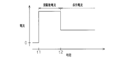
- the time chart which shows the change of an electric current value when the cutoff valve of a fuel supply apparatus is opened.
- the flowchart which shows the electricity supply prohibition process which the control apparatus of a fuel supply apparatus performs.
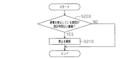
- the flowchart which shows the prohibition cancellation process which the control apparatus of a fuel supply apparatus performs.
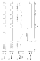
- (A) is a time chart showing the presence or absence of a valve opening command
- (b) is a time chart showing the presence or absence of energization of the open drive current
- (c) is a time chart showing the integrated value of the open drive current energization time
- (d) Is a time chart showing whether or not energization of the shutoff valve is prohibited.
- the fuel supply device is embodied as a fuel supply device that supplies fuel to a bi-fuel internal combustion engine mounted on a vehicle
- the fuel supply apparatus includes a CNG (compressed natural gas) supply system 40 and a gasoline supply system 30.
- the internal combustion engine 10 is a bi-fuel internal combustion engine that switches between CNG and gasoline.
- a CNG injector 12 and a gasoline injector 13 are attached in the intake passage 11 of the internal combustion engine 10.
- the fuel injected from the CNG injector 12 or the gasoline injector 13 and the intake air are mixed to generate an air-fuel mixture.
- the air-fuel mixture is sucked into the combustion chamber 15 and burned.
- the air-fuel mixture after combustion becomes exhaust and is discharged from the combustion chamber 15 through the exhaust passage 16.
- the internal combustion engine 10 is supplied with gasoline stored in a gasoline tank 31 as a fuel tank through a gasoline supply system 30 and supplied with CNG stored in a CNG tank 41 as a fuel tank through a CNG supply system 40. .
- a fuel pump 32 and a gasoline delivery pipe 33 are arranged in the gasoline supply system 30, a fuel pump 32 and a gasoline delivery pipe 33 are arranged.
- the fuel pump 32 sucks gasoline from the gasoline tank 31.
- the fuel discharged from the fuel pump 32 is pumped to the gasoline delivery pipe 33.
- the same number of gasoline injectors 13 as the number of cylinders of the internal combustion engine 10 are connected to the gasoline delivery pipe 33.
- the gasoline injector 13 injects the gasoline supplied from the gasoline delivery pipe 33 into the intake passage 11.
- a high-pressure fuel pipe 42 as a fuel supply passage connected to the CNG tank 41 and a delivery pipe 43 for CNG are arranged.
- the CNG delivery pipe 43 is connected to the downstream end of the high-pressure fuel pipe 42, that is, the right end of FIG.
- a manual open / close valve 44 which is a manual open / close valve, is disposed.
- An electric shut-off valve 45 is disposed in the high-pressure fuel pipe 42 downstream of the manual opening / closing valve 44.
- the electric shut-off valve 45 is opened and closed by a control device 50 that is a control unit of the fuel supply device.
- both the manual open / close valve 44 and the shutoff valve 45 are open, the inflow of CNG from the CNG tank 41 into the high pressure fuel pipe 42 is permitted.
- at least one of the manual open / close valve 44 and the shutoff valve 45 is closed, the inflow of CNG from the CNG tank 41 into the high pressure fuel pipe 42 is prohibited.
- a regulator 46 is disposed in the high-pressure fuel pipe 42 downstream of the shutoff valve 45.
- the regulator 46 reduces the pressure of CNG supplied from the CNG tank 41 to a predetermined pressure.
- CNG is supplied to the CNG delivery pipe 43 after being depressurized to a predetermined pressure.
- the same number of CNG injectors 12 as the number of cylinders of the internal combustion engine 10 are connected to the CNG delivery pipe 43.
- the CNG injector 12 injects CNG supplied from the CNG delivery pipe 43 into the intake passage 11.
- a pressure sensor SE1 electrically connected to the control device 50 is disposed in the CNG supply system 40.
- the pressure sensor SE1 detects the pressure Pa in the high-pressure fuel pipe 42 downstream from the shut-off valve 45.
- the control device 50 includes a microcomputer constructed by a CPU, a ROM, a RAM, and the like.
- the control device 50 is connected to an ignition switch 51 and a changeover switch 52 for switching the fuel to be used to CNG.
- the control device 50 uses CNG and gasoline separately as fuel used for engine operation.
- control device 50 drives gasoline supply system 30 and injects gasoline from gasoline injector 13. .
- the control device 50 basically closes the shutoff valve 45 of the CNG supply system 40.
- the control device 50 shifts the fuel supply mode to the second mode. And the control apparatus 50 opens the cutoff valve 45 of the CNG supply system 40, and injects CNG from the injector 12 for CNG.
- an opening driving current larger than a holding current for holding the shut-off valve 45 in an open state is supplied to cause the shut-off valve 45 to be driven with a large driving force. Open the valve. That is, when a valve opening command is output at timing t1, first, an opening driving current is supplied to the shutoff valve 45. Thereby, when the shut-off valve 45 is opened with a large driving force, a holding current smaller than the open drive current is supplied to the shut-off valve 45 after timing t2. Thereby, the opening of the shutoff valve 45 is maintained.
- the control device 50 opens the shut-off valve 45 and performs engine operation using CNG.
- the control device 50 opens and closes the cutoff valve 45 in order to confirm the operation of the cutoff valve 45. Based on this operation confirmation, the control device 50 determines that the shut-off valve 45 is operating normally when the shut-off valve 45 is opened and closed and the pressure Pa in the high-pressure fuel pipe 42 changes.
- the control device 50 changes the fuel supply mode from the first mode to the second mode. Transition. Thereby, supply of fuel from the CNG supply system 40 is started.
- ON / OFF of the ignition switch 51 and ON / OFF of the changeover switch 52 may be repeated, and a valve opening command for the shutoff valve 45 may be repeated.
- the open drive current is repeatedly passed through the shutoff valve 45. For this reason, the temperature of the shutoff valve 45 rises and the shutoff valve 45 may be damaged.
- the fuel supply device is configured to temporarily prohibit energization of the shutoff valve 45 with reference to the energization history of the open drive current.
- step S100 the control device 50 determines whether or not the integrated value of the open drive current energization time within a predetermined retroactive period is equal to or greater than the upper limit value.
- the RAM stores an energization history of the open drive current. Based on the energization history stored in the RAM, the control device 50 calculates the integrated value of the open drive current energization time from the time point retroactive by the retroactive period. Then, control device 50 compares the integrated value with the upper limit value of the integrated value. In order to be able to determine in advance that the shutoff valve 45 is overheated when the integrated value is equal to or higher than the upper limit value, the upper limit value is set based on the results of experiments performed in advance.
- step S110 the control device 50 starts energization prohibition processing for prohibiting energization of the shutoff valve 45. While the energization prohibition process is being executed, the control device 50 does not energize the shutoff valve 45 even if a valve opening command is output. That is, when the energization prohibition process is started through the process of step S110, energization to the shutoff valve 45 is prohibited.
- control device 50 also prohibits switching of the fuel supply mode from the first mode to the second mode.
- energization prohibition processing is started and energization to the shutoff valve 45 is prohibited, the control device 50 once ends this processing.
- step S100 when the integrated value of the open drive current energization time within the retroactive period is smaller than the upper limit value (step S100: NO), the control device 50 temporarily ends this process without executing the process of step S110. That is, when the integrated value does not reach the upper limit value, the energization prohibiting process is not started. Therefore, when the integrated value does not reach the upper limit value, the control device 50 energizes the shut-off valve 45 with an open driving current when a valve opening command is output.
- the series of processes shown in FIG. 4 is repeated by the control device 50 at a predetermined control cycle.
- the process shown in FIG. 4 is a process for canceling the prohibition of energization of the shutoff valve 45.
- step S200 the control device 50 determines whether or not the period during which energization to the shutoff valve 45 is prohibited, that is, the period after the energization prohibition process is started continues for a specified time or more. Determine.
- step S200 When the period during which energization to the shutoff valve 45 is prohibited continues for a specified time or longer (step S200: YES), the control device 50 advances the process to step S210.
- step S ⁇ b> 210 the control device 50 ends the energization prohibiting process that has been executed, and cancels the prohibition of energization of the shutoff valve 45.
- step S200 NO
- the control device 50 temporarily ends this series of processes without executing the process of step S210. That is, while the period during which energization is prohibited is less than the specified time, the energization prohibition process is not ended and is continued. In short, the energization prohibition process ends when the period during which energization to the shutoff valve 45 is prohibited continues for a specified time or longer.
- FIG. 5A As shown in FIG. 5A, during the period from timing t0 to t10, ON / OFF of the ignition switch 51 and the changeover switch 52 is repeated at short intervals. At this time, a valve opening command for the shutoff valve 45 is repeatedly output at short intervals.
- FIG. 5C the integrated value of the open drive current energization time within the retroactive period increases with the passage of time. At timing t10, the integrated value within the retroactive period reaches the upper limit value. Then, as shown in FIG. 5D, energization prohibition processing is started, and energization to the shutoff valve 45 is prohibited.
- shutoff valve 45 While the energization prohibition process is being executed during the period from timing t10 to t20, the shutoff valve 45 is not energized even if a valve opening command is output as shown in FIG. For this reason, as shown in FIG.5 (b), an open drive current is not supplied.
- the interval between the valve opening commands may not be short as in the period from timing t30 to t40 in FIG.
- the integrated value of the open drive current energization time within the retroactive period does not exceed the upper limit value. For this reason, as shown in FIG.5 (d), electricity supply to the cutoff valve 45 is not prohibited.
- Energization of the shut-off valve 45 is prohibited with reference to a plurality of open drive current energization histories within a retroactive period, not just a single open drive current energization period. That is, energization to the shutoff valve 45 can be prohibited based on the energization history indicating that the open drive current larger than the holding current has been energized repeatedly. Therefore, even if the valve opening command is repeatedly output, damage to the shutoff valve 45 can be suppressed.
- the temperature of the shutoff valve 45 decreases while the period during which no power is supplied continues. According to the above configuration, when the energization prohibition period is long and the temperature of the shutoff valve 45 is sufficiently lowered, the process of prohibiting energization of the shutoff valve 45 ends. Therefore, even if energization to the shutoff valve 45 is once prohibited, the prohibition of energization is not released until the overheat of the shutoff valve 45 is resolved. That is, when the overheating of the shutoff valve 45 is resolved, the prohibition of energization is released, and CNG can be supplied through the high pressure fuel pipe 42.
- the mode may be switched to the second mode using CNG.
- the fuel injection command is output to the CNG injector 12 even though the valve opening command of the cutoff valve 45 is output or the CNG cannot be supplied even though the valve opening of the cutoff valve 45 is prohibited. Or for this reason, the fuel supply device does not operate as instructed, and the operation of the fuel supply device becomes unstable.
- switching to the second mode is also prohibited. For this reason, said inconvenience can be suppressed.
- energization to the shutoff valve 45 is prohibited based on the energization history of the open drive current. In this way, taking into consideration the effects of energization of a plurality of open drive currents, energization is prohibited before the shutoff valve 45 is overheated, so that damage to the shutoff valve 45 is suppressed. That is, as long as the energization to the shutoff valve 45 can be prohibited before the shutoff valve 45 is damaged by overheating, the mode of energization history for prohibiting the energization to the shutoff valve 45 may be changed as appropriate. Specifically, instead of calculating the integrated value of the open drive current energization time within the retroactive period, the energization prohibition process is started when the open drive current energization count within the retroactive period exceeds the upper limit. May be.
- the temperature of the shutoff valve 45 rises greatly. For this reason, referring to the number of times of the open drive current energization within the retroactive period, the number of times when the temperature of the shutoff valve 45 is greatly increased during the retroactive period can be grasped, and the temperature of the shutoff valve 45 can be estimated. . That is, on the condition that the open drive current energization count is equal to or greater than the upper limit count, if the process of prohibiting energization to the shut-off valve 45 is started, the number of times that the temperature of the shut-off valve 45 has risen greatly increases, It can be estimated that the temperature of the shutoff valve 45 is high. If energization prohibition processing is started at this time, damage to the shutoff valve 45 is suppressed.
- the energization of the shutoff valve 45 may be prohibited. Instead of ending the energization prohibition process after the lapse of the specified time, the prohibition of energization to the shutoff valve 45 may be canceled based on the following conditions. For example, when the operation in the first mode continues for a specified time or longer, the energization prohibition process may be terminated.
- the prohibition canceling process for canceling the energization prohibiting process shown in FIG. 4 may be omitted. That is, even if the period during which energization is prohibited has passed the specified time, the prohibition of energization to the shutoff valve 45 may not be released. In this case, once energization is prohibited, the prohibition of energization may be canceled at the time of maintenance.
- the technical idea of prohibiting energization of the shutoff valve based on the energization history of the open drive current may be widely applied to fuel supply devices including the shutoff valve.
- the combination of the types of fuel supplied to the bi-fuel internal combustion engine by the fuel supply device is not limited to the combination of CNG and gasoline.
- the above technical idea may be applied to a fuel supply device that supplies fuel to an internal combustion engine that uses two or more types of fuel by switching.
Landscapes
- Engineering & Computer Science (AREA)
- Chemical & Material Sciences (AREA)
- Oil, Petroleum & Natural Gas (AREA)
- Combustion & Propulsion (AREA)
- Mechanical Engineering (AREA)
- General Engineering & Computer Science (AREA)
- Output Control And Ontrol Of Special Type Engine (AREA)
- Electrical Control Of Air Or Fuel Supplied To Internal-Combustion Engine (AREA)
- Control Of Vehicle Engines Or Engines For Specific Uses (AREA)
Abstract
燃料供給装置は、燃料タンクと、燃料タンクに貯留された燃料を供給する燃料供給通路と、燃料供給通路に配置されて通電により開弁する電動の遮断弁と、遮断弁への通電を制御する制御部とを備えている。制御部は、開弁状態を保持する保持電流よりも大きな開駆動電流を通電して遮断弁を開弁する。制御部は、遡及期間内における遮断弁への開駆動電流の通電履歴に基づいて(ステップS100)、遮断弁への通電を禁止する処理を実行する(ステップS110)。
Description
この発明は、電動の遮断弁を備えた燃料供給装置に関する。
特許文献1は、燃料供給通路に電動の遮断弁が設けられた燃料供給装置を開示する。特許文献1の燃料供給装置は、燃料により固着した遮断弁を開弁するため、遮断弁に大電流を流して遮断弁の駆動力を増大するように構成されている。ところが、遮断弁に大電流を流し続けると、遮断弁の温度が上昇し、遮断弁が損傷する。
上記の課題を解消するため、燃料供給装置のECUは、内燃機関停止時に遮断弁が閉じられてから内燃機関が停止するまでの時間を算出して記憶する。また、ECUは、内燃機関始動時に機関冷却水の温度と燃料の圧力とを検出する。また、ECUは、内燃機関が停止するまでにかかった時間と、始動時に検出された温度及び圧力とに基づいて、大電流を流して遮断弁を開弁する時間を算出する。そして、ECUは、算出された時間が経過するまでの間、大電流を流して遮断弁を駆動する。
例えば、内燃機関始動時、イグニッションスイッチのON・OFFが繰り返されることがある。このとき、各開弁指令に基づく遮断弁への通電期間は長くないものの、遮断弁に対する開弁指令が繰り返されることで、遮断弁に大電流が繰り返し通電される。その結果、大電流を流して遮断弁を駆動する期間を上記のように制限しても、遮断弁の温度が上昇し、遮断弁が損傷する虞がある。
この発明の目的は、開弁指令が繰り返されたとしても遮断弁の損傷を抑制することのできる燃料供給装置を提供することにある。
上記課題を解決するため、本発明の第一の態様によれば、燃料タンクと、燃料タンクに貯留された燃料を供給する燃料供給通路と、燃料供給通路に配置されて通電により開弁する電動の遮断弁と、遮断弁への通電を制御する制御部とを備え、制御部が開弁状態を保持する保持電流よりも大きな開駆動電流を通電して遮断弁を開弁する燃料供給装置が提供される。制御部は、遡及期間内における遮断弁への開駆動電流の通電履歴に基づいて、遮断弁への通電を禁止する処理を実行する。
上記構成によれば、遮断弁への通電が、一度の開駆動電流の通電期間だけでなく、遡及期間内の複数の開駆動電流の通電履歴を参照して禁止される。そのため、保持電流よりも大きな開駆動電流が繰り返し通電されたことを示す通電履歴に基づいて、遮断弁への通電を禁止することができる。従って、開弁指令が繰り返し出力されたとしても、遮断弁の損傷を抑制することができる。
上記の燃料供給装置において、遡及期間内における開駆動電流通電時間の積算値が上限値以上であることを条件に、制御部は、遮断弁への通電を禁止する処理を開始することが好ましい。
開駆動電流が通電されている間に、遮断弁の温度は大きく上昇する。一方、開駆動電流が通電されていないとき、遮断弁の温度は上昇しにくい。従って、遡及期間内における開駆動電流通電時間の積算値を参照すれば、遡及期間内において遮断弁の温度が大きく上昇した期間と、遮断弁の温度が大きく上昇しなかった期間との割合を把握し、遮断弁の温度を推定することができる。また、積算値が上限値以上である場合、遮断弁への通電を禁止する処理が開始される。そのため、遮断弁の温度が大きく上昇した期間の割合が高く、遮断弁の温度が高くなっていることが推定できる。このような場合、遮断弁への通電を禁止する処理を開始して、遮断弁の温度の更なる上昇を抑制することができる。
上記の燃料供給装置において、遡及期間内における開駆動電流通電回数が上限回数以上であることを条件に、制御部は、遮断弁への通電を禁止する処理を開始することが好ましい。
開駆動電流が通電されると、遮断弁の温度は大きく上昇する。このため、遡及期間内における開駆動電流通電回数を参照すれば、遡及期間内に遮断弁の温度が大きく上昇し得る状態の発生回数を把握できるため、遮断弁の温度を推定することができる。つまり、遮断弁の温度が大きく上昇し得る状態の発生回数が多く、遮断弁の温度が高くなっていることを推定することができる。このときに遮断弁への通電を禁止する処理を開始すれば、遮断弁の温度の更なる上昇が抑制される。
上記の燃料供給装置において、遮断弁への通電を禁止している期間が規定時間以上継続したことを条件に、制御部は、遮断弁への通電を禁止する処理を終了することが好ましい。
通電が行われない期間が継続している間に、遮断弁の温度は低下する。上記の構成によれば、通電を禁止している期間が長くなり、遮断弁の温度が十分に低下したときに、遮断弁への通電を禁止する処理が終了する。従って、一旦遮断弁への通電が禁止されても、遮断弁の過熱が解消されるまでは通電の禁止が解除されない。つまり、遮断弁の過熱が解消されたときに、通電の禁止を解除されて、遮断弁を配置した燃料供給通路を通じた燃料の供給が可能になる。
上記の燃料供給装置は、使用する燃料を切り替え可能に構成され、制御部は、通電が禁止されている遮断弁を配置した燃料供給通路を通じて供給される燃料を使用するモードへの切り替えを禁止することが好ましい。
遮断弁への通電が禁止されているとき、通電が禁止されている遮断弁を配置した燃料供給通路を通じて供給される燃料を使用するモードに切り替えられることがある。この場合、遮断弁の開弁が禁止されているにも拘わらず、遮断弁の開弁指令が出力されたり、燃料が供給できないにも拘わらず、燃料噴射指令が出力されたりする。このため、燃料供給装置が指令通りに動作しなくなり、燃料供給装置の動作が不安定になる。この点、上記構成によれば、遮断弁への通電が禁止されているときは、通電が禁止されている遮断弁を配置した燃料供給通路を通じて供給される燃料を使用するモードへの切り替えも禁止される。このため、上記の不都合を抑制することができる。
以下、燃料供給装置を、車両に搭載されるバイフューエル内燃機関に燃料を供給する燃料供給装置に具体化した一実施形態について、図1~図5(d)を参照して説明する。
図1に示すように、燃料供給装置は、CNG(圧縮天然ガス)供給系40と、ガソリン供給系30とを備えている。内燃機関10は、CNGとガソリンとを切り替えて使用するバイフューエル内燃機関である。
図1に示すように、燃料供給装置は、CNG(圧縮天然ガス)供給系40と、ガソリン供給系30とを備えている。内燃機関10は、CNGとガソリンとを切り替えて使用するバイフューエル内燃機関である。
内燃機関10の吸気通路11には、CNG用インジェクタ12及びガソリン用インジェクタ13が取り付けられている。吸気通路11では、CNG用インジェクタ12又はガソリン用インジェクタ13から噴射された燃料と吸入空気とが混合し、混合気が生成される。混合気は、燃焼室15に吸入されて燃焼される。燃焼後の混合気は、排気となり、燃焼室15から排気通路16を通じて排出される。
内燃機関10には、ガソリン供給系30を通じて、燃料タンクとしてのガソリンタンク31に貯留されたガソリンが供給され、CNG供給系40を通じて、燃料タンクとしてのCNGタンク41に貯留されたCNGが供給される。
ガソリン供給系30には、燃料ポンプ32と、ガソリン用デリバリパイプ33とが配置されている。燃料ポンプ32は、ガソリンタンク31からガソリンを吸引する。ガソリン用デリバリパイプ33には、燃料ポンプ32から吐出された燃料が圧送される。ガソリン用デリバリパイプ33には、内燃機関10の気筒数と同数のガソリン用インジェクタ13が連結されている。ガソリン用インジェクタ13は、ガソリン用デリバリパイプ33から供給されたガソリンを吸気通路11に噴射する。
CNG供給系40には、CNGタンク41に接続された燃料供給通路としての高圧燃料配管42と、CNG用デリバリパイプ43とが配置されている。CNG用デリバリパイプ43は、高圧燃料配管42の下流端、即ち、図1の右端に接続されている。CNGタンク41と高圧燃料配管42との間には、手動式の開閉弁である手動開閉弁44が配置されている。手動開閉弁44よりも下流の高圧燃料配管42には、電動の遮断弁45が配置されている。電動の遮断弁45は、燃料供給装置の制御部である制御装置50によって開閉される。
手動開閉弁44及び遮断弁45の双方が開弁している場合、CNGタンク41から高圧燃料配管42内へのCNGの流入が許可される。手動開閉弁44及び遮断弁45の少なくとも一方の弁が閉弁している場合には、CNGタンク41から高圧燃料配管42内へのCNGの流入が禁止される。
遮断弁45よりも下流の高圧燃料配管42には、レギュレータ46が配置されている。レギュレータ46は、CNGタンク41から供給されるCNGの圧力を所定圧力まで減圧する。CNGは、所定圧力まで減圧されてからCNG用デリバリパイプ43内に供給される。CNG用デリバリパイプ43には、内燃機関10の気筒数と同数のCNG用インジェクタ12が連結されている。CNG用インジェクタ12は、CNG用デリバリパイプ43から供給されたCNGを吸気通路11に噴射する。
CNG供給系40には、制御装置50に対し電気的に接続された圧力センサSE1が配置されている。圧力センサSE1は、遮断弁45よりも下流の高圧燃料配管42内の圧力Paを検出する。
制御装置50は、CPU、ROM及びRAMなどで構築されるマイクロコンピュータを備えている。制御装置50には、イグニッションスイッチ51と、使用する燃料をCNGに切り替えるための切り替えスイッチ52とが接続されている。制御装置50は、機関運転に使用する燃料として、CNGとガソリンとを使い分ける。
具体的には、ガソリンを用いた機関運転によって車両が走行する第1のモードが選択されている場合、制御装置50は、ガソリン供給系30を駆動して、ガソリン用インジェクタ13からガソリンを噴射する。第1のモードが選択されている場合、制御装置50は、基本的に、CNG供給系40の遮断弁45を閉弁する。一方、切り替えスイッチ52がONされてCNGを用いた機関運転により車両が走行可能となった状態では、制御装置50は、燃料供給モードを第2のモードに移行する。そして、制御装置50は、CNG供給系40の遮断弁45を開弁して、CNG用インジェクタ12からCNGを噴射する。
図2に示すように、制御装置50は遮断弁45を開弁する際、遮断弁45を開弁状態に保持する保持電流よりも大きな開駆動電流を流して、遮断弁45を大きな駆動力で開弁する。即ち、タイミングt1において開弁指令が出力されると、まず、開駆動電流が遮断弁45に通電される。これにより、大きな駆動力で遮断弁45が開弁されると、タイミングt2以降は、開駆動電流よりも小さな保持電流が遮断弁45に通電される。これにより、遮断弁45の開弁が保持される。
上述したように、第2のモードが選択されているとき、制御装置50は、遮断弁45を開弁状態にして、CNGを使用した機関運転を行う。しかしながら、イグニッションスイッチ51がONされかつ切り替えスイッチ52がONされたときも、制御装置50は、遮断弁45の動作確認のため、遮断弁45を開閉する。この動作確認により、制御装置50は、遮断弁45を開閉して高圧燃料配管42内の圧力Paが変化した場合に遮断弁45が正常に動作していると判定する。遮断弁45が正常に動作する状態でありかつ切り替えスイッチ52がONされているときに所定の移行条件が成立すると、制御装置50は、燃料供給モードを、第1のモードから第2のモードに移行する。これにより、CNG供給系40からの燃料の供給が開始される。
ところで、イグニッションスイッチ51のON・OFFや切り替えスイッチ52のON・OFFが繰り返されて、遮断弁45の開弁指令が繰り返されることがある。この場合、各開弁指令に基づく遮断弁45への通電期間は長くないものの、遮断弁45に開駆動電流が繰り返し通電される。このため、遮断弁45の温度が上昇し、遮断弁45が損傷する虞がある。このため、燃料供給装置は、開駆動電流の通電履歴を参照して、遮断弁45への通電を一時的に禁止するように構成されている。
次に、遮断弁45への通電を禁止する制御について図3及び図4を参照して説明する。図3に示す一連の処理は、制御装置50によって、遮断弁45の通電を禁止していないときに所定の制御周期で繰り返される。
図3に示すように、制御装置50は、ステップS100において、所定の遡及期間内における開駆動電流通電時間の積算値が上限値以上であるか否かを判定する。RAMには、開駆動電流の通電履歴が記憶されている。制御装置50は、RAMに記憶された通電履歴に基づいて、遡及期間の分だけ遡った時点からの開駆動電流通電時間の積算値を算出する。そして、制御装置50は、積算値を、その積算値の上限値と比較する。積算値が上限値以上になると遮断弁45が過熱されることを事前に判断できるようにするため、上限値は、予め行われた実験結果に基づいて設定されている。
遡及期間内における開駆動電流通電時間の積算値が上限値以上である場合(ステップS100:YES)、制御装置50は、処理をステップS110に進める。制御装置50は、ステップS110において、遮断弁45への通電を禁止する通電禁止処理を開始する。通電禁止処理が実行されている間は、開弁指令が出力されたとしても、制御装置50は、遮断弁45への通電を行わない。即ち、ステップS110の処理を通じて通電禁止処理が開始されると、遮断弁45への通電が禁止される。また、通電禁止処理が実行されている間は、制御装置50は、第1のモードから第2のモードへの燃料供給モードの切り替えも禁止する。通電禁止処理が開始されて遮断弁45への通電が禁止されると、制御装置50は、この処理を一旦終了する。
一方、遡及期間内における開駆動電流通電時間の積算値が上限値よりも小さい場合(ステップS100:NO)、制御装置50は、ステップS110の処理を実行せずに、この処理を一旦終了する。即ち、積算値が上限値に達しない場合、通電禁止処理は開始されない。そのため、積算値が上限値に達しない場合、制御装置50は、開弁指令が出力されたときに、開駆動電流を遮断弁45に通電する。
通電禁止処理が実行されているとき、即ち、遮断弁45への通電が禁止されているとき、図4に示す一連の処理が、制御装置50によって、所定の制御周期で繰り返される。図4に示す処理は、遮断弁45への通電の禁止を解除するための処理である。
図4に示すように、制御装置50は、ステップS200において、遮断弁45への通電を禁止している期間、即ち、通電禁止処理を開始してからの期間が規定時間以上継続したか否かを判定する。
遮断弁45への通電を禁止している期間が規定時間以上継続している場合(ステップS200:YES)、制御装置50は、処理をステップS210に進める。
制御装置50は、ステップS210において、実行していた通電禁止処理を終了し、遮断弁45への通電の禁止を解除する。
制御装置50は、ステップS210において、実行していた通電禁止処理を終了し、遮断弁45への通電の禁止を解除する。
遮断弁45への通電を禁止している期間が規定時間未満である場合(ステップS200:NO)、制御装置50は、ステップS210の処理を実行せずに、この一連の処理を一旦終了する。即ち、通電を禁止している期間が規定時間未満の間は、通電禁止処理は終了せず、継続される。要するに、通電禁止処理は、遮断弁45への通電を禁止している期間が規定時間以上継続したときに終了する。
次に、通電禁止処理を行う燃料供給装置の作用について図5(a)~図5(d)を参照して説明する。
図5(a)に示すように、タイミングt0~t10の期間では、イグニッションスイッチ51や切り替えスイッチ52のON・OFFが短い間隔で繰り返される。このとき、遮断弁45の開弁指令が、短い間隔で、繰り返し出力される。この場合、図5(c)に示すように、時間の経過と共に、遡及期間内における開駆動電流通電時間の積算値は大きくなる。そして、タイミングt10において、遡及期間内における積算値が上限値に達する。すると、図5(d)に示すように、通電禁止処理が開始されて、遮断弁45への通電が禁止される。
図5(a)に示すように、タイミングt0~t10の期間では、イグニッションスイッチ51や切り替えスイッチ52のON・OFFが短い間隔で繰り返される。このとき、遮断弁45の開弁指令が、短い間隔で、繰り返し出力される。この場合、図5(c)に示すように、時間の経過と共に、遡及期間内における開駆動電流通電時間の積算値は大きくなる。そして、タイミングt10において、遡及期間内における積算値が上限値に達する。すると、図5(d)に示すように、通電禁止処理が開始されて、遮断弁45への通電が禁止される。
タイミングt10~t20の期間で通電禁止処理が実行されている間は、図5(a)に示すように開弁指令が出力されたとしても、遮断弁45に通電されない。このため、図5(b)に示すように、開駆動電流が通電されない。
その後、タイミングt20において、通電を禁止している期間が規定時間に達すると、図5(d)に示すように、通電禁止処理が終了する。このため、遮断弁45への通電の禁止が解除される。通電禁止処理が終了すると、遮断弁45への通電が許可される。このため、図5(a)に示すように開弁指令が出力されている場合、図5(b)に示すように、通電禁止処理の終了と共に、開駆動電流の通電が再開される。
一方、イグニッションスイッチ51や切り替えスイッチ52のON・OFFが繰り返される場合であっても、図5(a)におけるタイミングt30~t40の期間のように、開弁指令の間隔が短くないこともある。この場合は、図5(c)に示すように、遡及期間内における開駆動電流通電時間の積算値は、上限値以上にならない。このため、図5(d)に示すように、遮断弁45への通電は禁止されない。
また、図5(a)におけるタイミングt50~t60の期間のように、開弁指令の間隔が短くない場合であっても、各開弁指令の継続期間が長くなることがある。この場合は、図5(c)に示すように、遡及期間内における開駆動電流通電時間の積算値が上限値に達する。このため、図5(d)に示すように、遮断弁45への通電が禁止される(タイミングt60~)。
以上、本実施形態によれば、以下の効果が得られる。
(1)遮断弁45への通電が、一度の開駆動電流の通電期間だけでなく、遡及期間内の複数の開駆動電流の通電履歴を参照して禁止される。つまり、保持電流よりも大きな開駆動電流が繰り返し通電されたことを示す通電履歴に基づいて、遮断弁45への通電を禁止することができる。従って、開弁指令が繰り返し出力されたとしても、遮断弁45の損傷を抑制することができる。
(1)遮断弁45への通電が、一度の開駆動電流の通電期間だけでなく、遡及期間内の複数の開駆動電流の通電履歴を参照して禁止される。つまり、保持電流よりも大きな開駆動電流が繰り返し通電されたことを示す通電履歴に基づいて、遮断弁45への通電を禁止することができる。従って、開弁指令が繰り返し出力されたとしても、遮断弁45の損傷を抑制することができる。
(2)開駆動電流が通電されている間に、遮断弁45の温度は大きく上昇する。一方、開駆動電流が通電されていないとき、遮断弁45の温度は上昇しにくい。従って、遡及期間内における開駆動電流通電時間の積算値を参照すれば、遡及期間内において遮断弁45の温度が大きく上昇した期間と、遮断弁45の温度が大きく上昇しなかった期間との割合を把握し、遮断弁45の温度を推定することができる。また、積算値が上限値以上である場合、遮断弁45への通電を禁止する通電禁止処理が開始される。こうして、遮断弁45の温度が大きく上昇した期間の割合が高く、遮断弁45の温度が高くなっていることを推定したときに、通電禁止処理を開始して、遮断弁45の温度の更なる上昇を抑制することができる。
(3)通電が行われない期間が継続している間に、遮断弁45の温度は低下する。上記構成によれば、通電を禁止している期間が長くなり、遮断弁45の温度が十分に低下したときに、遮断弁45への通電を禁止する処理が終了する。従って、一旦遮断弁45への通電が禁止されても、遮断弁45の過熱が解消されるまでは通電の禁止が解除されない。つまり、遮断弁45の過熱が解消されたときに、通電の禁止が解除されて、高圧燃料配管42を通じたCNGの供給が可能になる。
(4)通電禁止処理が実行されて遮断弁45への通電が禁止されているとき、CNGを使用する第2のモードに切り替えられることがある。この場合、遮断弁45の開弁が禁止されているにも拘わらず、遮断弁45の開弁指令が出力されたり、CNGが供給できないにも拘わらず、CNG用インジェクタ12に燃料噴射指令が出力されたりする。このため、燃料供給装置が指令通りに動作しなくなり、燃料供給装置の動作が不安定になる。上記構成によれば、通電禁止処理が実行されて遮断弁45への通電が禁止されているときは、第2のモードへの切り替えも禁止される。このため、上記の不都合を抑制することができる。
なお、本実施形態は、以下のように変更してもよい。
・本実施形態では、開駆動電流の通電履歴に基づいて遮断弁45への通電が禁止される。このようにすれば、複数の開駆動電流の通電の影響を加味して、遮断弁45に過熱が生じる前に通電が禁止されるため、遮断弁45の損傷が抑制される。つまり、過熱によって遮断弁45が損傷する前に遮断弁45への通電を禁止できる方法であれば、遮断弁45への通電を禁止する通電履歴の態様を、適宜変更してもよい。具体的には、遡及期間内における開駆動電流通電時間の積算値を算出したことに代えて、遡及期間内における開駆動電流通電回数が上限回数以上になったときに、通電禁止処理を開始してもよい。
・本実施形態では、開駆動電流の通電履歴に基づいて遮断弁45への通電が禁止される。このようにすれば、複数の開駆動電流の通電の影響を加味して、遮断弁45に過熱が生じる前に通電が禁止されるため、遮断弁45の損傷が抑制される。つまり、過熱によって遮断弁45が損傷する前に遮断弁45への通電を禁止できる方法であれば、遮断弁45への通電を禁止する通電履歴の態様を、適宜変更してもよい。具体的には、遡及期間内における開駆動電流通電時間の積算値を算出したことに代えて、遡及期間内における開駆動電流通電回数が上限回数以上になったときに、通電禁止処理を開始してもよい。
開駆動電流が通電されると、遮断弁45の温度は大きく上昇する。このため、遡及期間内における開駆動電流通電回数を参照すれば、遡及期間内に遮断弁45の温度が大きく上昇する状態になった回数を把握でき、遮断弁45の温度を推定することができる。つまり、開駆動電流通電回数が上限回数以上であることを条件に、遮断弁45への通電を禁止する処理を開始すれば、遮断弁45の温度が大きく上昇する状態になった回数が多く、遮断弁45の温度が高くなっていることを推定できる。このときに通電禁止処理を開始すれば、遮断弁45の損傷が抑制される。
・遡及期間内に遮断弁45に流れた電流値の積算値が上限値を超えたときに、遮断弁45への通電を禁止してもよい。
・規定時間経過後に通電禁止処理が終了することに代えて、以下の条件に基づいて、遮断弁45への通電の禁止を解除してもよい。例えば、第1のモードによる運転が規定時間以上継続した場合、通電禁止処理を終了してもよい。
・規定時間経過後に通電禁止処理が終了することに代えて、以下の条件に基づいて、遮断弁45への通電の禁止を解除してもよい。例えば、第1のモードによる運転が規定時間以上継続した場合、通電禁止処理を終了してもよい。
・図4に示す通電禁止処理を解除するための禁止解除処理を省略してもよい。つまり、通電を禁止している期間が規定時間を経過しても、遮断弁45への通電の禁止を解除しなくてもよい。この場合、一旦通電が禁止された後、整備の際に通電の禁止を解除すればよい。
・開駆動電流の通電履歴に基づき遮断弁への通電を禁止するとの技術的思想は、遮断弁を備える燃料供給装置に広く適用してもよい。同様の理由により、燃料供給装置によりバイフューエル内燃機関に供給される燃料の種類の組合せは、CNGとガソリンとの組合せに限定されない。また、上記の技術的思想は、2種類以上の燃料を切り替えて使用する内燃機関に燃料を供給する燃料供給装置に適用してもよい。
Claims (5)
- 燃料タンクと、前記燃料タンクに貯留された燃料を供給する燃料供給通路と、前記燃料供給通路に配置されて通電により開弁する電動の遮断弁と、前記遮断弁への通電を制御する制御部とを備え、前記制御部が開弁状態を保持する保持電流よりも大きな開駆動電流を通電して前記遮断弁を開弁する燃料供給装置において、
前記制御部は、遡及期間内における前記遮断弁への開駆動電流の通電履歴に基づいて、前記遮断弁への通電を禁止する処理を実行することを特徴とする燃料供給装置。 - 請求項1に記載の燃料供給装置において、
前記遡及期間内における開駆動電流通電時間の積算値が上限値以上であることを条件に、前記制御部は、前記遮断弁への通電を禁止する処理を開始することを特徴とする燃料供給装置。 - 請求項1に記載の燃料供給装置において、
前記遡及期間内における開駆動電流通電回数が上限回数以上であることを条件に、前記制御部は、前記遮断弁への通電を禁止する処理を開始することを特徴とする燃料供給装置。 - 請求項1~3のいずれか一項に記載の燃料供給装置において、
前記遮断弁への通電を禁止している期間が規定時間以上継続したことを条件に、前記制御部は、前記遮断弁への通電を禁止する処理を終了することを特徴とする燃料供給装置。 - 請求項1~4のいずれか一項に記載の燃料供給装置において、
前記燃料供給装置は、使用する燃料を切り替え可能に構成され、
前記遮断弁への通電を禁止する処理が実行されているとき、前記制御部は、通電が禁止されている遮断弁を配置した燃料供給通路を通じて供給される燃料を使用するモードへの切り替えを禁止する燃料供給装置。
Priority Applications (2)
| Application Number | Priority Date | Filing Date | Title |
|---|---|---|---|
| US15/032,404 US20160265451A1 (en) | 2013-11-28 | 2014-11-19 | Fuel supply device |
| CN201480064510.3A CN105874193A (zh) | 2013-11-28 | 2014-11-19 | 燃料供给装置 |
Applications Claiming Priority (2)
| Application Number | Priority Date | Filing Date | Title |
|---|---|---|---|
| JP2013246591A JP6050219B2 (ja) | 2013-11-28 | 2013-11-28 | 燃料供給装置 |
| JP2013-246591 | 2013-11-28 |
Publications (1)
| Publication Number | Publication Date |
|---|---|
| WO2015079997A1 true WO2015079997A1 (ja) | 2015-06-04 |
Family
ID=53198941
Family Applications (1)
| Application Number | Title | Priority Date | Filing Date |
|---|---|---|---|
| PCT/JP2014/080650 Ceased WO2015079997A1 (ja) | 2013-11-28 | 2014-11-19 | 燃料供給装置 |
Country Status (4)
| Country | Link |
|---|---|
| US (1) | US20160265451A1 (ja) |
| JP (1) | JP6050219B2 (ja) |
| CN (1) | CN105874193A (ja) |
| WO (1) | WO2015079997A1 (ja) |
Citations (4)
| Publication number | Priority date | Publication date | Assignee | Title |
|---|---|---|---|---|
| JP2623822B2 (ja) * | 1989-03-17 | 1997-06-25 | トヨタ自動車株式会社 | 自己制御型グロープラグの通電制御装置 |
| JP2001263210A (ja) * | 2000-03-16 | 2001-09-26 | Denso Corp | 電子制御装置及び記録媒体 |
| JP2013104343A (ja) * | 2011-11-14 | 2013-05-30 | Toyota Motor Corp | 燃料遮断弁診断装置 |
| JP2013204449A (ja) * | 2012-03-27 | 2013-10-07 | Keihin Corp | 燃料噴射システム |
Family Cites Families (9)
| Publication number | Priority date | Publication date | Assignee | Title |
|---|---|---|---|---|
| JPH0639935B2 (ja) * | 1985-03-04 | 1994-05-25 | トヨタ自動車株式会社 | デイーゼルエンジンの高圧電磁弁の通電制御方法 |
| DE19533131C2 (de) * | 1995-09-07 | 2001-01-18 | Siemens Ag | Verfahren und Vorrichtung zum Ansteuern eines elektromagnetischen Verbrauchers |
| JP2002021887A (ja) * | 2000-06-30 | 2002-01-23 | Isuzu Motors Ltd | クラッチ制御用電磁弁の保護方法 |
| US7318423B2 (en) * | 2002-03-06 | 2008-01-15 | Bosch Automotive Systems Corporation | DME fuel supply device for diesel engine |
| JP4617854B2 (ja) * | 2004-12-01 | 2011-01-26 | 株式会社デンソー | 電磁弁駆動装置 |
| JP2006336482A (ja) * | 2005-05-31 | 2006-12-14 | Denso Corp | 内燃機関用燃料噴射装置 |
| JP4508020B2 (ja) * | 2005-07-13 | 2010-07-21 | トヨタ自動車株式会社 | 燃料供給装置における電磁リリーフ弁の診断装置 |
| JP4338742B2 (ja) * | 2007-03-09 | 2009-10-07 | 三菱電機株式会社 | 内燃機関の高圧燃料ポンプ制御装置 |
| JP5605379B2 (ja) * | 2012-01-23 | 2014-10-15 | 株式会社デンソー | 電磁弁の駆動装置 |
-
2013
- 2013-11-28 JP JP2013246591A patent/JP6050219B2/ja not_active Expired - Fee Related
-
2014
- 2014-11-19 WO PCT/JP2014/080650 patent/WO2015079997A1/ja not_active Ceased
- 2014-11-19 CN CN201480064510.3A patent/CN105874193A/zh active Pending
- 2014-11-19 US US15/032,404 patent/US20160265451A1/en not_active Abandoned
Patent Citations (4)
| Publication number | Priority date | Publication date | Assignee | Title |
|---|---|---|---|---|
| JP2623822B2 (ja) * | 1989-03-17 | 1997-06-25 | トヨタ自動車株式会社 | 自己制御型グロープラグの通電制御装置 |
| JP2001263210A (ja) * | 2000-03-16 | 2001-09-26 | Denso Corp | 電子制御装置及び記録媒体 |
| JP2013104343A (ja) * | 2011-11-14 | 2013-05-30 | Toyota Motor Corp | 燃料遮断弁診断装置 |
| JP2013204449A (ja) * | 2012-03-27 | 2013-10-07 | Keihin Corp | 燃料噴射システム |
Also Published As
| Publication number | Publication date |
|---|---|
| JP6050219B2 (ja) | 2016-12-21 |
| CN105874193A (zh) | 2016-08-17 |
| US20160265451A1 (en) | 2016-09-15 |
| JP2015105581A (ja) | 2015-06-08 |
Similar Documents
| Publication | Publication Date | Title |
|---|---|---|
| CN104165098B (zh) | 车辆控制装置和车辆控制方法 | |
| JP2015132171A (ja) | 燃圧センサの異常判定装置 | |
| JP2009185676A (ja) | 内燃機関の燃料供給装置 | |
| WO2013099094A1 (ja) | 内燃機関の制御装置 | |
| WO2014136387A1 (ja) | 内燃機関の異常診断装置 | |
| JP6050219B2 (ja) | 燃料供給装置 | |
| JP2015194122A (ja) | 内燃機関の制御装置 | |
| JP2016070245A (ja) | 内燃機関の燃料噴射制御装置 | |
| JP2016217263A (ja) | 内燃機関の制御装置 | |
| JP6348339B2 (ja) | 内燃機関の燃料供給装置及びその制御方法 | |
| JP5373152B2 (ja) | エンジンの燃料供給装置 | |
| US10393053B2 (en) | Fuel injector of internal combustion engine and fuel injection method thereof | |
| JP2009243286A (ja) | エンジンの燃料供給システム | |
| JP2017115611A (ja) | 内燃機関の制御装置 | |
| JP7598782B2 (ja) | ポンプを作動させて水性作動液を供給する電動モータを制御する方法 | |
| JP5467926B2 (ja) | エンジンの燃料供給装置 | |
| JP4366692B2 (ja) | 内燃機関の二次エア供給システム | |
| JP6984968B2 (ja) | 内燃機関の制御装置 | |
| JP2007132191A (ja) | 内燃機関の燃料供給装置 | |
| JP2016153626A (ja) | 燃料噴射制御装置 | |
| KR102712322B1 (ko) | 엔진 공기 제어 장치 및 그 제어 방법 | |
| JP6790793B2 (ja) | エンジンの制御装置 | |
| JP6459463B2 (ja) | 燃料噴射システムの制御装置 | |
| JP2007056679A (ja) | エンジンのlpg燃料供給装置 | |
| WO2016031135A1 (ja) | 内燃機関の燃料噴射制御装置 |
Legal Events
| Date | Code | Title | Description |
|---|---|---|---|
| 121 | Ep: the epo has been informed by wipo that ep was designated in this application |
Ref document number: 14865627 Country of ref document: EP Kind code of ref document: A1 |
|
| WWE | Wipo information: entry into national phase |
Ref document number: 15032404 Country of ref document: US |
|
| NENP | Non-entry into the national phase |
Ref country code: DE |
|
| 122 | Ep: pct application non-entry in european phase |
Ref document number: 14865627 Country of ref document: EP Kind code of ref document: A1 |