WO2015076266A1 - 薬剤払出し装置 - Google Patents
薬剤払出し装置 Download PDFInfo
- Publication number
- WO2015076266A1 WO2015076266A1 PCT/JP2014/080525 JP2014080525W WO2015076266A1 WO 2015076266 A1 WO2015076266 A1 WO 2015076266A1 JP 2014080525 W JP2014080525 W JP 2014080525W WO 2015076266 A1 WO2015076266 A1 WO 2015076266A1
- Authority
- WO
- WIPO (PCT)
- Prior art keywords
- medicine
- container
- powder
- drug
- scraping
- Prior art date
- Legal status (The legal status is an assumption and is not a legal conclusion. Google has not performed a legal analysis and makes no representation as to the accuracy of the status listed.)
- Ceased
Links
Images


























Classifications
-
- B—PERFORMING OPERATIONS; TRANSPORTING
- B65—CONVEYING; PACKING; STORING; HANDLING THIN OR FILAMENTARY MATERIAL
- B65B—MACHINES, APPARATUS OR DEVICES FOR, OR METHODS OF, PACKAGING ARTICLES OR MATERIALS; UNPACKING
- B65B37/00—Supplying or feeding fluent-solid, plastic, or liquid material, or loose masses of small articles, to be packaged
- B65B37/16—Separating measured quantities from supply
- B65B37/18—Separating measured quantities from supply by weighing
-
- B—PERFORMING OPERATIONS; TRANSPORTING
- B08—CLEANING
- B08B—CLEANING IN GENERAL; PREVENTION OF FOULING IN GENERAL
- B08B1/00—Cleaning by methods involving the use of tools
- B08B1/10—Cleaning by methods involving the use of tools characterised by the type of cleaning tool
- B08B1/12—Brushes
-
- B—PERFORMING OPERATIONS; TRANSPORTING
- B08—CLEANING
- B08B—CLEANING IN GENERAL; PREVENTION OF FOULING IN GENERAL
- B08B1/00—Cleaning by methods involving the use of tools
- B08B1/30—Cleaning by methods involving the use of tools by movement of cleaning members over a surface
- B08B1/32—Cleaning by methods involving the use of tools by movement of cleaning members over a surface using rotary cleaning members
- B08B1/36—Cleaning by methods involving the use of tools by movement of cleaning members over a surface using rotary cleaning members rotating about an axis orthogonal to the surface
-
- B—PERFORMING OPERATIONS; TRANSPORTING
- B08—CLEANING
- B08B—CLEANING IN GENERAL; PREVENTION OF FOULING IN GENERAL
- B08B5/00—Cleaning by methods involving the use of air flow or gas flow
- B08B5/04—Cleaning by suction, with or without auxiliary action
-
- B—PERFORMING OPERATIONS; TRANSPORTING
- B08—CLEANING
- B08B—CLEANING IN GENERAL; PREVENTION OF FOULING IN GENERAL
- B08B7/00—Cleaning by methods not provided for in a single other subclass or a single group in this subclass
- B08B7/04—Cleaning by methods not provided for in a single other subclass or a single group in this subclass by a combination of operations
-
- B—PERFORMING OPERATIONS; TRANSPORTING
- B65—CONVEYING; PACKING; STORING; HANDLING THIN OR FILAMENTARY MATERIAL
- B65B—MACHINES, APPARATUS OR DEVICES FOR, OR METHODS OF, PACKAGING ARTICLES OR MATERIALS; UNPACKING
- B65B1/00—Packaging fluent solid material, e.g. powders, granular or loose fibrous material, loose masses of small articles, in individual containers or receptacles, e.g. bags, sacks, boxes, cartons, cans, or jars
- B65B1/04—Methods of, or means for, filling the material into the containers or receptacles
-
- B—PERFORMING OPERATIONS; TRANSPORTING
- B65—CONVEYING; PACKING; STORING; HANDLING THIN OR FILAMENTARY MATERIAL
- B65B—MACHINES, APPARATUS OR DEVICES FOR, OR METHODS OF, PACKAGING ARTICLES OR MATERIALS; UNPACKING
- B65B1/00—Packaging fluent solid material, e.g. powders, granular or loose fibrous material, loose masses of small articles, in individual containers or receptacles, e.g. bags, sacks, boxes, cartons, cans, or jars
- B65B1/30—Devices or methods for controlling or determining the quantity or quality or the material fed or filled
- B65B1/32—Devices or methods for controlling or determining the quantity or quality or the material fed or filled by weighing
-
- B—PERFORMING OPERATIONS; TRANSPORTING
- B65—CONVEYING; PACKING; STORING; HANDLING THIN OR FILAMENTARY MATERIAL
- B65B—MACHINES, APPARATUS OR DEVICES FOR, OR METHODS OF, PACKAGING ARTICLES OR MATERIALS; UNPACKING
- B65B37/00—Supplying or feeding fluent-solid, plastic, or liquid material, or loose masses of small articles, to be packaged
-
- B—PERFORMING OPERATIONS; TRANSPORTING
- B65—CONVEYING; PACKING; STORING; HANDLING THIN OR FILAMENTARY MATERIAL
- B65B—MACHINES, APPARATUS OR DEVICES FOR, OR METHODS OF, PACKAGING ARTICLES OR MATERIALS; UNPACKING
- B65B65/00—Details peculiar to packaging machines and not otherwise provided for; Arrangements of such details
-
- G—PHYSICS
- G07—CHECKING-DEVICES
- G07F—COIN-FREED OR LIKE APPARATUS
- G07F11/00—Coin-freed apparatus for dispensing, or the like, discrete articles
- G07F11/46—Coin-freed apparatus for dispensing, or the like, discrete articles from movable storage containers or supports
- G07F11/50—Coin-freed apparatus for dispensing, or the like, discrete articles from movable storage containers or supports the storage containers or supports being rotatably mounted
- G07F11/54—Coin-freed apparatus for dispensing, or the like, discrete articles from movable storage containers or supports the storage containers or supports being rotatably mounted about vertical axes
-
- G—PHYSICS
- G07—CHECKING-DEVICES
- G07F—COIN-FREED OR LIKE APPARATUS
- G07F17/00—Coin-freed apparatus for hiring articles; Coin-freed facilities or services
- G07F17/0092—Coin-freed apparatus for hiring articles; Coin-freed facilities or services for assembling and dispensing of pharmaceutical articles
Definitions
- the powder is a drug in the form of powder or granules
- the “medicine” includes powder.
- the device of the present invention is a device for handling powders in principle, but powders may be referred to as drugs when it is not necessary to distinguish powders from other forms of drugs.
- large hospitals and large-scale pharmacies have introduced powder dispensing devices and drug dispensing devices having a powder dispensing function.
- the powder medicine packaging device is an apparatus for individually packaging powder medicine or the like for each dose. If the powder medicine packaging device is used, it is possible to automate most of the work of packaging powder medicines one by one.
- the powder packaging device 900 disclosed in Patent Document 1 is a device for individually packaging powder for each dose, and as shown in FIG. Device 903.
- the powder feeder 906 is provided with a piezoelectric element (not shown) under the trough 910 and vibrates the trough 910.
- the powder distribution device 902 includes a distribution tray 912 and a scraping device 915.
- the distribution tray 912 has a large opening at the center.
- the distribution tray 912 is surrounded by a groove 916 having a circular cross section and an annular shape in plan view around the opening.
- Distribution tray 912 is rotated at a constant speed by motor 919.
- the scraping device 915 includes a lifting arm whose tip is lifted and lowered by rotating, and a scraping mechanism.
- the scraping mechanism has a disk 917 that is rotated by a motor, and a scraping plate 918 is provided on the disk 917.
- the medicine packaging device 903 includes a packaging hopper 920 and a packaging device 921 as shown in FIG.
- the operation of packaging the powder is performed by the pharmacist operating the powder packaging device 900 in accordance with a doctor's prescription. That is, the pharmacist confirms the doctor's prescription and takes out the medicine bottle containing the prescribed powder from a medicine shelf (not shown). Then, the total weight of the specific powder prescribed using a balance such as a balance is measured. Then, the weighed powder is put into the charging hopper 905 of the drug supply device 901. At the same time, the piezoelectric element (not shown) of the powder feeder 906 is energized to vibrate the trough 910 and further rotate the distribution tray 912.
- the scraping device includes a scraping arm that moves up and down on the tip side, and a scraping mechanism provided at the tip of the scraping arm, the distribution tray has an equipment storage opening, and the scraping arm and / or A motor for driving the scraping mechanism, and a part or all of the motor is in the equipment storage opening, and the proximal end side of the scraping arm is in or just above the equipment storage opening and the tip side is It is preferable to have a lid that cantilevered from the equipment storage opening side and covers the motor. If it does in this way, there are few unevenness
- the container mounting device is equipped with a weight measuring means, it is possible to detect the discharge amount of the medicine and to automate the work of measuring the powder or the like.
- a part or all of the drug container is a magnetic body, and the container holding means has a magnet. If it does in this way, since a medicine container is held by magnetic force, attachment and detachment of a medicine container is easy.
- a plurality of distribution dishes are provided and a partition wall is provided between the distribution dishes.
- Some powders have very small particles and are likely to float in the air. Some powders have relatively large and light particles, and such powders may fly at that moment when they are ejected from the distribution tray. Therefore, in the medicine dispensing device having a plurality of distribution trays, there is a concern that the powder that floats or flies falls to the nearby distribution tray. In view of this, a partition wall was provided between the distribution dishes so that even if the powder floated, it would not go to the adjacent distribution dish.
- the drug dispensing device of the present invention has less overall unevenness and is easy to clean.
- the medicine dispensing device of the present invention is less likely to cause contamination of powder and has high safety.
- FIG. 70 is an exploded perspective view of the cleaning brush in FIG. 70. It is sectional drawing which shows the state which is cleaning the scraping mechanism of the arm for scraping, (a) shows the state where a brush exists in parts other than a partition plate, and a brush is near the scraping mechanism, (B) shows a state in which the brush is in the part of the partition plate and the brush is close to the scraping mechanism, and (c) shows that the brush is in the part of the partition plate and the brush is separated from the scraping mechanism. Indicates the state.
- the perspective view which shows the modification of the chemical
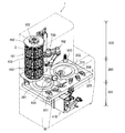
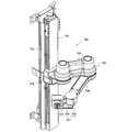
- a container moving means 700 is provided in an area from the medicine shelf area 100 to the medicine division area 200. As shown in FIG. 43, the container moving means 700 is configured such that a robot 702 is provided on an elevating mechanism 701 provided in a vertical direction.
- the robot 702 has two arm members 705 and 706 and a hand portion 707.
- the hand portion 707 is provided with an electromagnet and can hold the iron plate of the medicine container 2 by magnetizing.
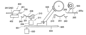
- the medicine division area 200 is an area in which two distribution dishes 201 are installed in an embedded state, and the container mounting device 3 and the cleaning device 500 are arranged around the area. Further, a scraping device 930 is provided in the medicine division region 200, and a scraping arm 931 of the scraping device 930 projects from each distribution tray 201 of the medicine division region 200. That is, the medicine division region 200 includes a flat table member 205.
- the table member 205 is a flat surface on which an object can be placed. That is, the table member 205 has a table surface 205a on which an article can be placed. As shown in FIG. 17, the table member 205 is provided with two distribution tray receiving openings 206.
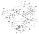
- the scraping device 930 includes a scraping side power transmission system 932 and an arm side power transmission system 933 as shown in FIG.
- the scraping-side power transmission system 932 includes a motor 950, and the scraping mechanism 606 provided on the scraping arm 931 can be driven by operating the motor 950.
- the arm side power transmission system 933 includes a motor 960, and the scraping arm 931 can be moved up and down by operating the motor 960.
- a turntable 604 is provided under the table member 205, and a scraping arm 931 is fixed to the turntable 604. Therefore, the entire scraping device 930 can be turned by turning the turntable 604.
- a lid 207 (covering member) is provided in the equipment storage opening 210 of the distribution tray 201 and covers the motors 950 and 960 (FIG. 21).
- the lid 207 is fixed to the turntable 604 side and rotates integrally with the turntable 604.
- the outer diameter of the lid 207 is substantially equal to the equipment storage opening 210 provided in the center of the distribution tray 201 and enters the equipment storage opening 210.
- the lid 207 does not abut or engage with the distribution tray 201, and the lid 207 and the distribution tray 201 can be rotated relative to each other.
- the lid 207 has a substantially flat top surface except for a part of the protrusions. More specifically, when the lid 207 is viewed in plan, more than three quarters of the area is smooth.
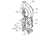
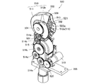
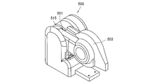
- the cleaning device 500 has a cleaning arm 501 that protrudes in a cantilevered manner from the table member 205 side and whose tip side is raised and lowered by power, and a cleaning brush 502 is provided at the tip.
- the cleaning brush 502 is rotatably mounted in the brush cover 503.
- the brush cover 503 has an opening 503a (exposure opening) on the distal end side, and a part of the cleaning brush 502 is exposed from the opening 503a.
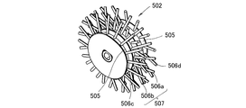
- the cleaning brush 502 is obtained by flocking around the hub member.
- four rows of hair are provided around the hub member.
- the outer flocking rows are all provided such that the hair tip side faces inward.
- one of the central row of flocks is flocked to the right and the other is flocked to the left.
- the flocking rows of the cleaning brush 502 are provided over three or more rows, and the flocking rows on both end sides include a centrally inclined hair group in which the hair tip side is flocked in a direction inclined toward the center side of the hub member,
- the side flocking row has one end-direction inclined hair group planted in a direction in which the hair end side is inclined toward one end side of the hub member, and a direction in which the hair end side is inclined toward the other end side of the hub member. And the other end-direction inclined hair group.
- the hub member is provided with a groove between the flocking rows.
- the table member 205 is provided with the container placing device 3.
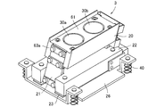
- the container mounting device 3 includes a vibration table 20 and a weight measuring unit 25 that directly or indirectly measures the weight of the medicine container 2.
- the main parts of the container mounting device 3 are all buried below the table member 205, and only a part including the surface of the vibration table 20 is exposed from the table member 205.
- the vibration table 20 is provided with container holding means for temporarily fixing the drug container 2 to the vibration table 20.
- the container holding means is specifically a magnet. More specifically, the electromagnet has a structure called a self-holding solenoid 30.
- the self-holding solenoid 30 is a combination of a permanent magnet and an electromagnet, and always exhibits an attracting force mainly by the permanent magnet.
- the electromagnet is energized to generate a magnetic force in the direction opposite to that of the permanent magnet, thereby canceling the magnetic force of the permanent magnet.
- the magnet is energized to generate a magnetic force in the same direction as that of the permanent magnet at the time of adsorption, and a current in the reverse direction is supplied to generate a magnetic force in the direction opposite to that of the permanent magnet at the time of separation.
- the medicine container 2 can be placed on the container placement device 3, and the vibration table 20 can be vibrated to discharge the medicine from the medicine container 2. Further, the weight change of the drug container 2 at that time is detected by the weight measuring means 25.
- the table member 205 is further provided with a medicine injection opening 241. Further, a hopper closing member 400 is provided at a position slightly away from the medicine input opening 241 of the table member 205 to the front side.
- the hopper closing member 400 has a main body portion 401 and an inner lid portion 402, and the inner lid portion 402 moves in a direction away from the main body portion 401 by power.
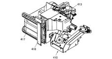
- the medicine packaging apparatus 410 is a machine for packaging a medicine for each dose, similarly to the known one, and is constituted by a packaging paper supply apparatus and a packaging apparatus as is well known. Further, a powder injection hopper 413 (drug input hopper) for supplying the drug to the packaging part is provided.
- the drug packaging device of this embodiment moves as a whole in the front-rear direction as a unique configuration. That is, in this embodiment, the medicine packaging apparatus 410 moves as a whole.
- the opening of the powder injection hopper 413 is located at the position of the medicine input opening 241, and when the packaging operation is completed, the medicine packaging device 410 moves to the front side as a whole and the powder The charging opening of the charging hopper 413 reaches the position of the hopper closing member 400. And after that, cleaning work, such as powder injection hopper 413, is carried out.
- a remaining medicine detection sensor is provided in all of the distribution tray 201, the powder injection hopper 413, and the scraping mechanism 606.
- the remaining medicine detection sensor is an optical sensor, has a main body device and a fiber, and the tip portion of the fiber is provided in the distribution tray 201 or the like or in the vicinity thereof.
- a partition wall (not shown) may be provided between the two distribution dishes 201. When the partition is provided, there is no possibility that the powder in one distribution tray 201 is scattered on the other distribution tray 201. Moreover, it is preferable to provide a partition cleaning means for cleaning the partition. That is, it is possible to avoid a situation where the powder adhering to the partition wall is scattered and mixed into different types of drugs.
- the medicine dispensing apparatus 1 automatically performs an operation of selecting a medicine according to a prescription, an operation of feeding a predetermined amount of medicine into the distribution tray 201, and an operation of dividing the medicine into the medicine packaging device 410. Can be done. Thereafter, the distribution tray 201 is automatically cleaned, and the scraping mechanism 606 is also automatically cleaned. After that, the powder injection hopper 413 is also automatically cleaned.
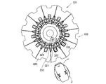
- the medicine dispensing apparatus 1 of this embodiment automatically selects the medicine container 2 according to the prescription. Specifically, the drum member 102 of the container storage device 101 is rotated to bring the desired medicine container 2 closer to the container moving means 700.
- the hand container 707 of the container moving means 700 holds the drug container 2 and operates an arm or the like to place the drug container 2 on the vibration table 20 of the container placing device 3.
- medical agent container 2 is installed in the container mounting apparatus 3.
- the vibration table 20 is vibrated.
- the powder in the medicine container 2 moves slowly, is discharged from the medicine container 2, and falls to the distribution tray 201.
- the distribution tray 201 of the powder distribution device 202 is rotated before and after the start of vibration.
- the weight of the drug container 2 is measured before and after the start of vibration.
- the weight of the medicine container 2 is monitored, and the vibration of the shaking table 20 is stopped when the total amount of powder drops reaches a desired weight. That is, the original weight G, which is the weight of the drug container 2 before discharging the drug, is measured by the weight measuring means 25, and the weight of the drug container 2 is determined by the weight measuring means 25 when the powder medicine is discharged little by little from the drug container 2. Monitor.
- the current weight g which is the current weight of the drug container 2
- the discharge of powder from the drug container 2 is stopped.
- the rotation of the distribution tray 201 is stopped.
- the motor 950 (FIG. 21) is rotated forward to swing the scraping arm 931, the tip side is lowered to lower the scraping mechanism 606, and the scraping mechanism 606 is placed in the medicine loading groove 208 of the distribution tray 201.
- the distribution plate 201 is rotated by an angle corresponding to the number of distributions and scraped to the scraping plate 609.
- the motor 950 is rotated in the reverse direction, the scraping plate 609 is rotated, the drug is scooped up by the scraping plate 607, discharged from the distribution tray 201, and loaded into the drug loading opening 241.
- the cleaning arm 501 is rotated to raise the cleaning brush 502 provided at the tip, and the cleaning brush 502 is taken out from the medicine charging groove 208 of the distribution tray 201.
- the suction by the suction means is preferably continued while the cleaning brush 502 is raised.
- the medicine adhering to the cleaning brush 502 when the cleaning brush 502 is raised can be prevented from falling onto the distribution tray 201.
- the remaining medicine detection sensor 372 confirms the cleaning state of the distribution tray 201 after cleaning the distribution tray 201, the distribution tray 201 continues to rotate even after the cleaning brush 502 is raised. Therefore, while the distribution plate 201 is still rotated, the cleaning brush 502 is continuously rotated while performing suction by the suction means, and after the cleaning brush 502 is lifted, the cleaning brush 502 is rotated and suction by the suction means is stopped. To do.
- the medicine dispensing device 1 of the present embodiment is equipped with a cleaning mechanism according to the operation, shape, and application of each mechanism, the cleaning performance is greatly improved, contamination of powder is unlikely to occur, and safety is high. .
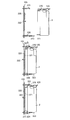
- the mounting detection member 322 has a protruding member.
- the mounting detection member 322 is located below the upper engagement portion 325, and the protruding member protrudes outward from the vertical wall 320.
- the protruding member also maintains a state of protruding outward by a biasing member (not shown).
- the urging member that urges the protruding member has a weak urging force, and when pressed against something, the protruding member easily immerses inside the drum member 102. In other words, the protruding member normally protrudes toward the outside of the drum member 102, but when the drug container 2 is attached to the container setting unit 103, the protruding member is pushed by the drug container 2 and enters the drum member 102. It protrudes to the inside of the drum member 102.
- a pop-up detection sensor 330 is provided in the vicinity of the drum member 102.
- the pop-up detection sensor 330 is an optical sensor including a light emitter 331 and a light receiver 332.
- the light emitter 331 is provided near the drum member 102 and on the upper side.
- the light receiver 332 is provided at a position below the light emitter 331 in the vertical direction.
- the straight line of light connecting the light emitter 331 and the light receiver 332 of the pop-up detection sensor 330 is parallel to the drum member 102. Further, the straight line of light does not intersect with the rotation locus when the drum member 102 is rotated in a state where the medicine container 2 is accurately attached to the container setting portion 103.
- the rotation locus when the drum member 102 is rotated. Interact with.
- the medicine container 2 blocks the light emitted from the light emitter 331, and the light receiver 332 The incident light is interrupted. Therefore, in the present embodiment, it is possible to detect whether or not the drug container 2 already attached to the container setting unit 103 is attached in a normal posture by driving the guard motor 302 and rotating the drum member 102.
- An information read / write device 335 such as an RFID reader is provided in the vicinity of the drum member 102.
- the container installation unit 103 is provided in three stages, a total of three information read / write devices 335 are provided, one for each stage.
- the information read / write device 335 is operated at an appropriate timing, and the type of medicine contained in each medicine container 2 is read from the RFID attached to each medicine container 2 and stored in a control device (not shown). To do. That is, the position where the medicine container 2 is mounted and the medicine contained therein are associated with each other and stored in the control device. Moreover, it is used for the purpose of rewriting information already stored in the control device or checking the contents.
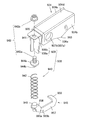
- the scraping arm 931 has an elongated, rectangular column-shaped casing, and a cavity is formed inside the casing. That is, the housing of the scraping arm 931 has a structure in which four sides are surrounded by a pair of opposing side plates 934a and 934b, a top plate 934d, and a bottom plate 934c. A proximal side plate 935 is provided on the proximal end side of the scraping arm 931.
- the positioning pin 952 is a round bar-like member, and a rack portion 955 is formed on the side surface of the cylinder.
- the distal end side of the positioning pin 952 is tapered like a pencil.
- the tapered tip portion of the positioning pin 952 can be engaged with the groove 672 of the fixed side engaging member 670 installed outside the turntable 604.
- the positioning pin 952 is disposed on the turntable 604.
- the positioning pin 952 is orthogonal to the axis of the drive shaft 960a of the motor 960.
- a gear 951 (pinion) attached to the drive shaft 960 a is engaged with the rack portion 955 of the positioning pin 952. That is, when the motor 960 is driven in the forward direction and the reverse direction, power is transmitted from the gear 951 to the rack portion 955, and the positioning pin 952 reciprocates linearly.
- the turntable 604 can be rotated.
- the scraping arm 931 is raised. That is, the swinging member 947 of the swinging mechanism 962 shown in FIGS. 23 and 76 is stopped by rotating counterclockwise around the shaft member 614, and the mounting portion 959 of the mounting member 945 is raised. Therefore, the scraping arm 931 in which the pressing surface 936a is pressed by the mounting portion 959 is in the ascending posture illustrated in FIG.
- the hopper obstruction member 400 has a main body portion 401 and an inner lid portion 402.
- the main body 401 is a plate having a substantially rectangular planar shape and a thickness of about 1 cm.
- the area of the inner lid portion 402 is smaller than the area of the main body portion 401.
- the shape of the inner lid portion 402 is substantially rectangular and is similar to the main body portion.
- the outer surface of the inner lid portion 402 is made of resin.
- the inner lid portion 402 is arranged in parallel to the main body portion 401 and is guided so as to approach and separate while maintaining a parallel state. Further, a motor (opening / closing mechanism) and a cam are incorporated between the inner lid portion 402 and the main body portion 401.
- a suction device 415 is connected to the middle part of the powder injection hopper 413.
- the suction device 415 is a known vacuum suction machine, and includes a negative pressure generating device such as a blower and a vacuum hose.
- the vacuum hose is connected to the middle part of the powder injection hopper 413.
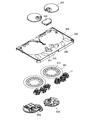
- the table member 205 is made of a smooth and glossy plate made of stainless steel or the like as shown in FIG.
- the table member 205 has a table surface 205a.
- the table surface 205 a constitutes the upper surface of the table member 205.
- the table member 205 is provided with distribution tray accommodation openings 206 at two locations. That is, two distribution tray receiving openings 206 are opened on the table surface 205a.
- three container placement device openings 240 are provided around each of the distribution tray housing openings 206.
- a medicine input opening 241 and a closing member installation opening 242 are provided between the distribution tray housing openings 206.
- the distribution tray receiving opening 206 is a circular opening having a large outer diameter.
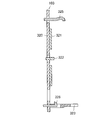
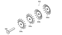
- the cleaning brush 502 is obtained by integrating a central brush 507 with side disk-like brushes 506c and 506d on both sides of the central brush 507 and inserting a rotating shaft 508 into the three.
- Each disk brush is integrally fixed to the rotation shaft 508 and does not allow relative rotation.
- a gear is provided at the end of the rotating shaft 508.
- the brush cover 503 has two side walls 510 and a peripheral wall 509 that connects the ends of the two side walls except for the opening 513.
- Each of the two side walls 510 is formed by integrating an arcuate surface portion 511 having a little less than about 180 degrees and an extended wall portion 512 in which both ends of the arcuate surface portion 511 are extended.
- the extension wall portion 512 has straight sides on the left and right sides and an arc at the tip side. Therefore, one side of the side wall 510 is an arcuate side.
- An opening 513 is formed between the arc-shaped side portions of the two side walls 510.
- the cleaning brush 502 described above is rotatably disposed in the brush cover 503. Most of the cleaning brush 502 is accommodated in the space in the brush cover 503, and only a part is exposed from the opening 513. A gear 504 provided on the cleaning brush 502 is exposed outside the brush cover 503. The brush cover 503 is attached to the tip of the cleaning arm 501 in a state where the cleaning brush 502 is included.
- a series of gear trains from the gear 520 provided in the brush motor 519 to the gear 504 provided in the cleaning brush 502 are formed, and there is a series of power transmission paths. Therefore, when the brush motor 519 is rotated, the cleaning brush 502 attached to the distal end side of the cleaning arm 501 is rotated.
- the hand part 707 has a wrist part 708 and a container holding palm part 709.
- the wrist 708 is an arm shorter than the arm members 705 and 706 described above.
- the wrist 708 is attached to the tip of the second arm member 706 via a vertical shaft (not shown), and rotates in the horizontal direction around the tip of the second arm member 706 by driving the motor.
- the wrist 708 is higher than the arm members 705 and 706 described above, and a motor is built in the arm member.
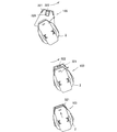
- the container holding palm part 709 When taking out the medicine container 2 from the container setting part 103 of the drum member 102, the container holding palm part 709 is set in a vertical posture and brought close to the medicine container 2 as shown in FIG. Then, the container holding palm portion 709 is pressed against the transporting iron plate portion 157 attached to the medicine container 2. Thereafter, the electromagnet provided in the container holding palm portion 709 is energized to adsorb the transporting iron plate portion 157 provided in the drug container 2. Then, the arm members 705 and 706 are retracted and the medicine container 2 is extracted. Then, the arm member or the like is operated to move the medicine container 2 to the vicinity of the lower distribution tray 201. Further, the posture of the container holding palm portion 709 is changed to a parallel posture as shown in FIG.
- the medicine container 2 is returned to the drum member 102 through the reverse route.
- the drum member 102 is rotated while the wrist part 708 of the hand part 707 is horizontally rotated as shown in FIG. It is made to oppose the container installation part 103.
- FIG. That is, the container installation portion 103 of the drum member 102 of the present embodiment has the side surface support member 321 as described above, and the side surface support member 321 has an opening angle equivalent to that of the fixing iron plate portion 6 of the container body 5. is doing. Therefore, the surface of the drum member 102 is not flat, and a part of the side support member 321 protrudes radially. Therefore, when the container moving means 700 is easily moved and the medicine container 2 is brought close to the drum member 102, the medicine container 2 hits the side support member 321.
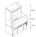
- the drug dispensing device 1 of the present embodiment has a structure in which a frame is made of steel and each member and device are attached to the frame. Further, the frame is entirely covered with the housing 7, and the inside and outside are shielded. A dehumidifying device and a temperature controller are provided in the housing 7, and the internal temperature and humidity are maintained within a certain range. In addition, two fans are provided on the top surface of the housing 7 so that the inside of the housing 7 can be ventilated.
- the casing 7 is roughly divided into a shelf area casing 100 a that covers the drug shelf area 100, a divided area casing 200 a that covers the drug dividing area 200, and a packaging area casing 300 a that covers the medicine packaging area 300. .
- the shelf area casing 100a and the divided area casing 200a are made of a transparent resin, and the inside can be observed.
- the packaging region casing 300a is made of a steel plate, and the inside cannot be seen.
- the shelf area casing 100a has a smaller planar occupation area than the other two. Therefore, the shelf area housing 100a is designed to be placed on the medicine division area 200. In the present embodiment, the shelf area housing 100a is located on the left side as viewed from the front. Therefore, only a part of the upper part of the medicine division region 200 communicates with the shelf region housing 100a, and the remaining part does not communicate with the ceiling surface.
- a large sliding door 105 is provided in the divided area housing 200a.
- the front wall of the medicine division area 200 is provided with guide rails at both ends thereof, and the lower half of the front wall of the division area housing 200a is fitted, and the door portion is opened and closed by a motor (not shown). To do.
- the position of the container side engaging portion 352 is the position on the peripheral wall lower surface 12 and slightly closer to the lid member 120 than the center, and does not hit the vibration table 20 when the medicine container 2 is installed on the vibration table 20.
- the container side engaging portion 352 is ring-shaped, and is provided with a square hole 351 penetrating in the longitudinal direction of the medicine container 2.
- the container side engaging portion 352 of the medicine container 2 is inserted through the opening 346, the medicine container 2 is pushed down, and the protrusion (the upper part on the storage portion side) of the container installing portion 340 is inserted into the hole 351 of the container side engaging portion 352.
- the drug container 2 is suspended to the container setting part 340 by inserting the engagement part to the container engagement part) 347.
- the protrusion (storage part side lower engagement part) 348 provided on the mounting table 343 engages with the recess 371 of the medicine container 2.
- the container installation part 340 of this embodiment has a protrusion (storage part side upper engagement part vs.
- the drum member 102 is provided, and the container setting portion 103 is arranged in a circumferential shape.
- the present invention is not limited to this configuration, and the container installation part 340 may be arranged in a plane as shown in FIG.
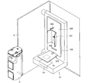
- the overall structure of the medicine dispensing apparatus 800 in the modified example is as shown in FIG. 50, for example.
- the medicine dispensing apparatus 800 is functionally divided into a medicine shelf area 803, a medicine division area 805, and a medicine packaging area 806 in the vertical direction.
- medicine container storage shelves 801 are arranged in the periphery, and a medicine container moving device 802 is provided therein.
- the medicine shelf region 803 is dehumidified by a dehumidifying device (not shown). Further, a dust collector (not shown) is provided inside the medicine shelf area 803, and dust in the medicine shelf area 803 is removed.
- a blower fan is provided in the medicine shelf region 803, and the air in the medicine shelf region 803 is circulated by the blower fan.
- a filter is provided in a fixed ventilation path such as the intake side of the blower fan to remove dust and the like floating in the drug shelf region 803.
- the drug container moving device 802 has a vertical lift shaft 810, a horizontal movement arm 808, and a hand portion 812 for holding the drug container 2.
- the horizontal movement arm 808 has joints 813 and 814 at two locations as shown in FIG.
- the hand unit 812 can change the posture of the medicine container 2. Note that the drug container moving device 802 employs the hand portion 812 of the electromagnet 807.
- a shelf member 815 is provided in the medicine shelf region 803, and the shelf member 815 is placed on the rail 816.
- a rack (not shown) is provided near the rail 816.
- the shelf member 815 is provided with a travel motor, and the travel motor is provided with a pinion and is engaged with the rack.
- the shelf member 815 moves in the front-rear direction as a whole, and moves forward to approach the distribution tray 201 when taking out the medicine container 2.
- FIG. 57 shows an example in which an opening / closing means is provided in the container holding palm portion 709 of the hand portion 707.
- the hand unit 707 shown in FIG. 57 is a container holding palm unit 709 provided with an opening 426 on a surface pressed against the medicine container 2.
- An opening / closing member 419 is provided in the opening 426.
- the opening / closing member 419 is an “L” -shaped member, and has contact members 420 and 421 on two sides. The opening / closing member 419 swings around the base portions of the contact members 420 and 421 on the two sides.
- the opening / closing member 419 is swung by power such as a solenoid or a motor (not shown).
- a knob portion (operation portion) 147 provided on the movable lid portion 134 of the container main body 5 enters the opening 426 of the hand portion 707 as shown in FIG.
- the knob portion 147 enters between the contact members 420 and 421 on the two sides of the opening / closing member 419.
- the opening / closing member 419 is swung left and right as indicated by an arrow by a solenoid or the like (not shown).
- the opening / closing member 419 engages with the knob portion 147, the knob portion 147 swings, and the movable lid portion 134 is opened / closed.
- Opening / closing means for the movable lid 134 of the container body 5 may be provided in the container mounting device 3. Moreover, you may install the opening / closing means of the independent movable cover part 134. FIG.
- the drug container 2 is installed in the container installation unit 103 of the drum member 102 as described above, and is held and moved by the hand unit 707 of the robot 702, as shown in FIG. It is mounted on the container mounting device 3. If the medicine container 2 is moved in a horizontal posture, immediately before the medicine container 2 is installed on the container mounting device 3, the medicine discharge section 8 side of the medicine container 2 is up as shown in FIG. In this way, it is desirable to incline once. By inclining the medicine container 2 so that the medicine discharge section 8 side is up, the powder in the powder storage section 17 is moved away from the medicine discharge section 8 side. This posture changing operation prevents the powder from spilling when the movable lid 134 is opened.
- the magnet on the hand portion 707 side is turned off, and the container body 5 is fixed to the container placing device 3 side by the magnetic force generated on the container placing device 3 side.
- the magnetic force on the 3 side is stopped, the magnet on the hand portion 707 side is turned on, and the container body 5 is held on the hand portion 707 side.
- FIG. 67 shows an example in which a cover 220 is provided on the upper surface side of the distribution tray 201 in order to meet this requirement.
- the cover 220 covers an area of 30% to 100% of the distribution tray 201. In this embodiment, an area of about 30 percent of the distribution tray 201 is covered.
- the cover 220 is fixed to the table member 205 and is cantilevered on the distribution plate 201 with the table member 205 side as a base end.
- the height of the cover 220 is a height at which the scraping plate 609 does not interfere when the scraping mechanism 606 is moved to the cleaning device 500 side. That is, the scraping arm 931 of the scraping device 930 is raised on the upper side to move the scraping mechanism 606 to the upper side, and the turntable 604 is further rotated to move the scraping mechanism 606 to the cleaning device 500 side. At that time, the scraping plate 609 and the like pass over the cover 220.
- the cover 220 is missing in the vicinity of the cleaning device 500.
- the cover 220 is configured by one central cover member 222 and two end cover members 223.
- the central cover member 222 is installed across the two distribution trays 201 and covers a region from the vicinity of the powder injection hopper 413 to the vicinity of the cleaning device 500.
- a partition wall 221 is suspended below the center covering member 222.
- the lower end of the partition wall 221 is fixed to the table member 205. Therefore, the partition wall 221 also functions as a support member that supports the central covering member 222.
- the end cover member 223 is located on both sides of the central cover member 222, but there is a gap for inserting the cleaning brush 502 of the cleaning device 500 between the end cover member 223 and the central cover member 222. It is secured.
- the hopper closing member 400 is also provided with a partition wall 430.
- the partition wall 430 provided on the hopper closing member 400 is movable and protrudes and retracts from the hopper closing member 400.
- FIG. 69 is an exploded perspective view of members related to the partition wall 430 in the hopper closing member 400.
- the hopper closing member 400 includes a main body portion 431, a cleaning member 432, and a partition wall 430.
- the main body 431 has a slit 433 formed from the top surface to the side surface.
- a concave portion 424 for mounting the cleaning member 432 is provided on the top surface of the main body portion 431.
- Engaging grooves 425 are provided on both sides of the recess 424.
- the partition wall 430 has a plate shape and is inserted into the slit 433 in the top surface portion of the main body portion 431.
- the partition wall 430 has a rotation shaft 435.
- a motor (not shown) for rotating the rotation shaft 435 is incorporated in the main body 431, and the partition wall 430 is in the slit 433 and rotates about the rotation shaft 435.
- a cleaning member 432 is provided on the top surface of the main body 431.
- the cleaning member 432 is a thin member, and includes a frame member 436 made of metal and a central member 437.
- the frame member 436 is a member having three sides when viewed in a plan view.
- the central member 437 is a thin plate made of rubber or resin that is soft but slightly waisted.
- the central member 437 is provided with a slit 438.
- the slit 438 has a notch shape that is open at one end side.
- the width of the slit 438 is narrower than the width of the slit 433 provided in the main body portion 431. Further, the width of the slit 438 is narrower than the thickness of the partition wall 430.
- the cleaning member 432 is attached to the recess 424 on the top surface of the main body 431. The side portions on both sides of the cleaning member 432 are engaged with an engagement groove 425 provided in the recess 424, and the cleaning member 432 is slid forward or rearward by the engagement groove 425.
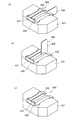
- the partition wall 430 rotates from the posture protruding to the side of the main body portion 431 as shown in FIG. 68 (a), and becomes the posture of being accommodated in the slit 433 of the main body portion 431.
- the partition wall 430 passes through the slit 438 of the central member 437.
- the central member 437 is made of a soft or slightly elastic rubber or resin, and the width of the slit 438 is narrower than the thickness of the partition wall 430, so that the partition wall 430 passes through the slit 438.
- the slits 438 of the central member 437 wipe the both side surfaces of the partition wall 430.
- the cleaning member 432 can be detached from the main body 431 by sliding the cleaning member 432 with respect to the main body 431. Therefore, the cleaning member 432 can be removed and cleaned with water or the like. .
- FIG. 51 is a medicine container temporary placement unit 250 of another embodiment.
- the medicine container temporary placement part 250 is attached to the door part 9 and moves together with the door part 9.
- the medicine container temporary placement unit 250 includes a placement table 251, an engagement lever 252, and a holding member 253.
- the holding member 253 has a fence shape and holds the drug container 2.
- the mounting table 251 includes a backrest portion 255 arranged in an upright posture or a slightly inclined posture, and a pedestal portion 256 arranged in a substantially horizontal posture.
- the backrest portion 255 has a rectangular and large installation portion 257 at the center, and rectangular side portions 258a and 258b on both sides thereof.
- the side portions 258a and 258b are inclined toward the front side with respect to the installation portion 257.
- the engagement lever 252 is disposed in the notch portion 260 of the pedestal portion 256.
- the engaging lever 252 and the holding member 253 are engaged, and when the engaging lever 252 is lowered, the holding member 253 is raised.
- the engagement lever 252 is made by bending a metal plate.
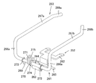
- the engagement lever 252 is a kind of lever, and as shown in FIG. 56, there is a fulcrum region 261 at the center, a container contact portion 262 that is a force point on one end side, and an action portion 263 on the other side.
- the fulcrum area 261 is an area where the plate material is bent in an “L” shape, and a swing shaft 265 is provided at the corner.
- one end of the fulcrum area 261 is bent to provide a container abutting portion 262.
- the action part 263 is provided by bending the other end of the fulcrum area 261.
- the action portion 263 is provided with a hole 264.
- the holding member 253 is made by bending a wire to the left and right objects.
- the holding member 253 has a rotation shaft portion 269 at the center, and both ends thereof are bent to form connecting portions 266a and 266b.
- side holding portions 267a and 267b are provided by bending the distal ends of the connecting portions 266a and 266b in a direction away from the rotating shaft portion 269.
- maintenance part 268a, 268b is provided by bending the front end side of the side holding
- the engaging lever 252 swings about the swing shaft 265 with the swing shaft 265 engaged with a frame (not shown).
- the holding member 253 is in the vicinity of the engagement lever 252, and the rotation shaft portion 269 is arranged in parallel with the swing shaft 265 of the engagement lever 252.
- the holding member 253 swings about the rotation shaft portion 269 with the rotation shaft portion 269 being held by the bearing 273.
- the engagement lever 252 and the holding member 253 are engaged via the spring 270 and the connection fitting 271.
- the connection fitting 271 is integrally attached to the rotation shaft portion 269 of the holding member 253.
- a hole 275 is provided in the connection fitting 271.
- the spring 270 is a torsion coil spring having a coil portion 274 at the center and engaging portions at both ends. In the spring 270, the coil portion 274 is attached to the holding member 253 with the rotation shaft portion 269 as the center.
- One engaging portion of the spring 270 is engaged with the hole 264 of the action portion 263 of the engaging lever 252.
- the other engaging portion of the spring 270 is engaged with the hole 275 of the connection fitting 271 attached to the holding member 253.
- the engagement lever 252 rotates clockwise with reference to FIG. 56, and the spring 270 rotates counterclockwise. Then, the holding member 253 engaged with the spring 270 rotates counterclockwise to raise the side holding portions 267a and 267b and the front side holding portions 268a and 268b. In addition, the container contact portion 262 of the engagement lever 252 always protrudes upward from the notch portion 260 of the base portion 256 of the mounting table 251.
- the drug container 2 When the drug container 2 is attached to the drug container temporary placement unit 250, the drug container 2 is placed on the mounting table 251 using a human hand or the hand unit 707 of the robot 702. As described above, the container contact portion 262 of the engagement lever 252 protrudes upward from the notch portion 260 of the mounting table 251, so that when the drug container 2 is placed on the mounting table 251, the container contact portion 262 is shaken. It moves and sinks, and instead, the side holding portions 267a and 267b and the front side holding portions 268a and 268b rise.
- maintains the side surface of the chemical
- the fixing iron plate part 6 side of the medicine container 2 is held by the backrest part 255 of the mounting table 251. Accordingly, the medicine container 2 is held on the five surfaces by the pedestal portion 256 and the backrest portion 255 of the mounting table 251 and the side holding portions 267a and 267b and the front side holding portions 268a and 268b of the holding member 253, and does not fall off.
- the scraping member 280 (cleaning portion) is provided at a position directly above the medicine container temporary placement portion 250.
- the scraping member 280 is provided not on the door portion 9 but on the main body side of the medicine dispensing device 1.
- the scraping member 280 has a concave portion 281 (container contact portion) whose cross-sectional shape follows the shape of the container body 5.
- a suction port 282 is opened inside the recess 281 (container contact portion), and the suction port 282 is connected to a suction device (not shown).
- FIG. 52 is an exploded perspective view of the scraping member 280
- FIG. 53 is a cross-sectional perspective view of the scraping member 280.
- the scraping member 280 is constituted by a main body 283 and a wiping member 234.
- the main body 283 is made of a hard resin, and is provided with the recess 281a as described above.
- the wiping member 234 is made of a soft resin such as silicon rubber or rubber, and is provided with a recess 281b as in the case of the main body 283.
- the wiping member 234 is attached to the lower portion of the main body portion 283 with a slight gap therebetween.
- the tip of the recess 281b of the wiping member 234 is at a position protruding slightly before the tip of the recess 281a of the main body 283, as shown in FIG. As described above, there is a slight gap between the wiping member 234 and the main body 283, and the gap serves as the suction port 282.
- the scraping member 280 is a member provided for cleaning the side surface of the medicine container 2.
- the medicine is supplied directly from the medicine container 2 to the distribution tray 201. For this reason, after the medicine is supplied, the medicine may adhere to the side surface of the medicine container 2 due to the influence of static electricity or the like.
- the drug may stick to the vicinity of the drug discharge portion 8 of the drug container 2. Therefore, the side surface of the medicine container 2 is pressed against the recess 281 (container contact part) of the scraping member 280, and the medicine container 2 is slid downward or upward. At the same time, a suction device (not shown) is activated.
- the wiping member 234 protrudes from the main body 283. Therefore, when the medicine container 2 is slid downward or upward, the side of the medicine container 2 and the vicinity of the medicine discharge portion 8 are wiped by the wiping member 234, and the sticking medicine is removed. Thus, the medicine adhering to the side surface of the medicine container 2 is wiped off and sucked into the suction device from the suction port 282. Therefore, even if a drug residue remains on the side surface of the drug container 2, it is cleaned by the scraping member 280.
- the medicine container 2 is attached to the medicine container temporary placement unit 250 using a human hand or the hand part 707 of the robot 702, but the medicine container temporary placement is performed using the hand part 707 of the robot 702.
- the used medicine container 2 is returned to the container setting section 103 of the drum member 102 by the robot 702, it is desirable to wipe the side surface of the medicine container 2 with the scraping member 280 and then attach it to the medicine container temporary placement section 250.
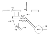
- FIG. 60 is a conceptual diagram of an embodiment provided with a function of supplying a cleaning agent into the powder injection hopper 413 during a cleaning operation. In the embodiment shown in FIG.
- a cleaning agent charging device 423 is provided in the vicinity of the introduction side opening of the powder charging hopper 413. Further, an opening / closing plate 416 is provided at the discharge side opening (medicine discharge port) at the end of the powder injection hopper 413, and an air nozzle 422 is provided in the vicinity of the outside of the opening / closing plate 416.
- the powder injection hopper 413 has, for example, a shape as shown in FIG. 65, and has a discharge side opening (drug discharge port) 1000 at the lower part and an introduction side opening 1001 at the upper part.
- An opening / closing plate 416 is provided in the discharge side opening 1000.
- a suction opening 1002 is opened on the side surface of the powder injection hopper 413.
- the suction opening 1002 is at least above the discharge side opening 1000 and at a height closer to the introduction side opening 1001 than the discharge side opening 1000.
- the extension line of the central axis XX in the planar direction of the suction opening 1002 passes near the central axis ZZ of the powder injection hopper 413.
- the suction opening 1002 is provided at the center of the side surface of the powder injection hopper 413 in plan view.
- the shape of the suction opening 1002 is flat, and the width is wider than the length.
- a pipe member 1010 such as a pipe or a hose is connected to the suction opening 1002, and the end of the pipe member 1010 is connected to the suction device 415. That is, the tube member 1010 constitutes a part of the suction path from the suction opening 1002 to the suction device 415.
- the pipe member 1010 has a curved portion 1012. That is, in the present embodiment, the position near the suction opening 1002 in the suction path is greatly curved. That is, when the tube member 1010 is viewed from above, a curved portion 1012 is recognized.
- the suction opening 1002 is flat. Therefore, the air flow velocity in the vicinity of the suction opening 1002 is different between the side near the outside of the curve and the side near the inside.
- the hopper cleaning operation performed by introducing the cleaning agent is performed according to the following procedure.
- a cleaning agent is charged into the powder injection hopper 413.
- the opening / closing plate 416 at the end of the powder injection hopper 413 is closed.
- the charging opening of the powder charging hopper 413 is closed by the hopper closing member 400.
- the suction member is operated.
- a violent air flow is generated in the powder injection hopper 413 and the cleaning agent swirls vigorously and collides with the inner wall of the powder injection hopper 413.
- the open / close plate 416 at the end of the powder charging hopper 413 is closed, the amount of air supplied into the powder charging hopper 413 is limited.
- the cleaning agent swirls in the powder injection hopper 413, the amount of air sucked by the suction member is small. Therefore, the cleaning agent is merely stirred in the powder injection hopper 413 and the amount sucked out by the suction member is small. Therefore, the cleaning agent stops in the powder injection hopper 413 and collides with the inner wall of the powder injection hopper 413 for a long time. Moreover, the impact of the collision is large because the centrifugal force of the cleaning agent acts on the inner surface of the powder injection hopper 413 as if it were a cyclone type vacuum cleaner. Therefore, the medicine adhering to the inner wall of the powder charging hopper 413 is peeled off.
- the opening / closing plate 416 at the end of the powder injection hopper 413 is opened. More preferably, the opening and closing of the opening / closing plate 416 is repeated. As a result, outside air is introduced from the end of the powder charging hopper 413 into the powder charging hopper 413, which tends to be negative pressure, a more intense air flow is generated in the powder charging hopper 413, and the cleaning agent swirls vigorously and powder is charged. The medicine that collides with the inner wall of the hopper 413 and adheres to the inner wall of the powder injection hopper 413 is peeled off.
- the suction opening 1002 is flat and is a suction path, and the position immediately adjacent to the suction opening 1002 is greatly curved, the air flow rate in the vicinity of the suction opening 1002 is outside the curve. It is different between the side close to and the side close to the inside. In the present embodiment, the air flow rate increases near the inner wall 1003, and the air flow rate decreases near the opposing inner wall 1006. Therefore, a strong swirl flow is generated in the powder injection hopper 413. In addition, air is introduced from a discharge-side opening 1000 provided in the lower part of the powder injection hopper 413. Therefore, the air flow advances from the lower side to the upper side with the swirling along the inner wall of the powder injection hopper 41.
- the supplied cleaning agent acts on the inner wall of the powder injection hopper 41 to scrape off the drug, rolls it together with the cleaning agent, and discharges it by the suction member.
- the suction opening 1002 is provided in the vicinity of the upper end of the powder charging hopper 413, almost all the inner walls of the powder charging hopper 413 are cleaned.
- the peeled medicine is sucked out together with the cleaning agent by the suction member and discharged out of the powder injection hopper 413.
- stirring of the cleaning agent in a state where the cleaning agent is stopped at the powder injection hopper 413 and stirring of the cleaning agent performed while discharging a part of the cleaning agent by introducing air are repeated. Will be.
- the drug attached to the outer surface of the opening / closing plate 416 itself is removed by blowing air from an air nozzle 422 provided in the vicinity of the opening / closing plate 416. That is, according to the experience of the present inventors, the medicine may adhere to the opening / closing plate 416 provided in the discharge side opening 1000 of the powder injection hopper 413.
- the inner side of the opening / closing plate 416 (the inner surface side of the powder injection hopper 413) can be cleaned by using the above-mentioned cleaning agent by the impact of stirring, but the outer surface of the opening / closing plate 416 itself collides with the cleaning agent. I can't let you. Therefore, in the present embodiment, air is blown directly from the air nozzle 422 provided in the vicinity of the opening / closing plate 416 toward the outside of the opening / closing plate 416 to remove the drug attached to the outside of the opening / closing plate 416.
- the opening / closing plate 416 is provided at a position deep in the normal apparatus, it is difficult to apply air injection when the opening / closing plate 416 closes the discharge side opening 1000. Therefore, in the present embodiment, the air nozzle 422 is provided at a position where the jetted air hits when the opening / closing plate 416 is in the open position. Further, since there is a wrapping paper in the vicinity of the opening / closing plate 416, the medicine separated by air is collected in the wrapping paper. A series of operations will be described together. A cleaning agent is introduced into the powder injection hopper 413 and suction is started. In the latter half of the suction, the opening / closing plate 416 is opened and closed. Blow air directly towards the outside. Stop suction and air after 5-10 seconds.
- the cleaning agent charging device 423 is provided in the vicinity of the opening on the introduction side of the powder charging hopper 413.
- the cleaning agent may be charged into the powder charging hopper 413 using the drug container 2.
- the cleaning agent charging device 423 is provided as the cleaning agent charging unit for charging the cleaning agent.
- the medicine container 2 may be used as the cleaning agent charging unit.
- a specific medicine container 2 is filled with a cleaning agent such as baking soda and stored in the container storage device 101 like the other medicine containers 2. Then, the cleaning agent in the medicine container 2 is put into the powder injection hopper 413 by an operation according to the operation of taking out the powder from the normal medicine container 2 and putting it in the powder injection hopper 413.
- the cleaning agent is automatically or manually filled.
- the drug container 2 is selected.
- the hand 707 of the robot 702 holds the medicine container 2, moves the medicine container 2, and places the medicine container 2 filled with the cleaning agent on the container placement device 3.
- the anti-vibration table 23 of the container mounting device 3 is operated to load the powder from the drug container 2 to the distribution tray 201 of the powder distribution device 202.
- the cleaning agent is discharged from the distribution tray 201 by the scraping device 930, and is supplied to the powder injection hopper 413. This series of operations is executed at a speed higher than the operation speed at the time of normal medicine packaging.
- the opening / closing plate 416 is closed when the medicine is supplied from the medicine container 2 to the powder injection hopper 413, but when the cleaning agent is supplied to the powder injection hopper 413, the opening / closing plate is used. 416 is closed.
- the remaining medicine detection sensor 372 (hereinafter simply referred to as “remaining medicine detection sensor 372”) for the distribution tray 201 is an optical sensor, and is a unit in which a light projecting unit and a light receiving unit are integrated. As shown in FIG. 66, the light projecting unit of the remaining medicine detection sensor 372 emits a beam having a width corresponding to the width of the medicine insertion groove 208 of the distribution tray 201. The light projecting part of the remaining medicine detection sensor 372 is fixed, and the region irradiated with the beam is limited to a certain region.
- the light irradiated from the light projecting part is regularly reflected on the surface of the medicine throwing groove 208 and does not return to the light receiving part.
- the light irradiated from the light projecting unit will be diffusely reflected upon the remaining drug or the like, and a part of the light enters the light receiving unit of the remaining drug detection sensor 372. Therefore, it is possible to detect whether there is dirt or residual medicine in the irradiation unit.
- the residual medicine detection operation is performed by irradiating light from the light projecting portion of the residual medicine detection sensor 372 (hereinafter simply referred to as the residual medicine detection sensor 372) while rotating the distribution tray 201. Specifically, after cleaning the surface of the distribution tray 201 by the cleaning device 500, the remaining medicine detection operation is performed. As described above, the distribution tray 201 is cleaned by rotating the distribution tray 201 one or more times (for example, twice) while rotating the cleaning brush 502. Thereafter, the rotation of the cleaning brush 502 is stopped, and the distribution tray 201 is further rotated one or more times. At that time, light is emitted from the light projecting portion of the remaining medicine detection sensor 372 to inspect whether there is dirt or remaining medicine.
- the cleaning brush 502 is rotated again to clean the distribution tray 201 again. If there is no remaining medicine or the like in the distribution tray 201, the cleaning arm 501 is rotated to raise the cleaning brush 502 provided at the tip, and the cleaning brush 502 is taken out from the medicine insertion groove 208 of the distribution tray 201.
- the remaining medicine detection sensor 372 detects dirt or remaining medicine despite cleaning the surface of the distribution tray 201
- a configuration may be adopted in which the user is notified by sound or video. The user can visually check the state of the distribution tray 201 with the notification as an opportunity, and can confirm whether the cause of the notification is dirt, foreign matter, or drug residue.
- the alarm has a release mode and a skip mode.
- the release mode is a mode in which the alarm that has been issued is stopped and cleaning with the cleaning brush 502 is performed again.
- the skip mode is a mode in which an alarm is given, but cleaning by the cleaning brush 502 is not performed, and the user confirms the presence or absence of remaining medicine and manually cleans as necessary.
- the cleaning brush 521 employed in the present embodiment is used in place of the cleaning brush 502 in the cleaning device 500 shown in FIGS.
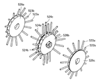
- the cleaning brush 521 has a hub member 522 provided with two grooves 525 and 526 (FIG. 72) as in the case of the cleaning brush 502 described above, and the circumferential surface of the hub member 522 is flocked.
- the cleaning brush 521 of this embodiment has a structure in which three disk-like brushes 526a, 526b, and 526c are connected.
- the side surface disc-shaped brushes 526a and 526c are flocked.
- the hair bundles 523a and 523b (center direction inclined hair group) implanted in the disk-like brushes 526a and 526c are all inclined toward the center.
- the hair bundles 523 (planted rows) planted on the disk-shaped brushes 526a and 526c include a long hair bundle 523a and a short hair bundle 523b.
- the center disk-shaped brush 526b is implanted in two rows.
- the hair bundles 524 implanted in each row include a hair bundle 524a (an inclined hair group in one end direction) whose hairs are long and inclined toward the side surface, and a hair bundle 524b (the other end) where the hairs are short and inclined toward the side surface.
- the scraping mechanism 606 is a member having a scraping plate 609, a scraping plate 607, and a partition plate 603.
- the scraping plate 609, the scraping plate 607, and the partition plate 603 are integrally configured.
- a circumferential seal material 683 of rubber or resin is provided so as to be in close contact with the medicine charging groove 208 of the distribution tray 201.
- a rubber or resin scraping sealing material 685 is also provided at the end of the scraping plate 607 so as to be in close contact with the medicine charging groove 208.
- the cleaning brush 521 is pressed against the side surfaces of the scraping plate 609, the scraping plate 607, and the partition plate 603, the circumferential portion sealing material 683, and the scraping sealing material 685 to perform cleaning. Therefore, in principle, as shown in FIGS. 72A and 72B, the scraping plate 609 of the scraping mechanism 606 and the partition plate 603 are inserted deeply into the grooves 525 and 526 of the cleaning brush 521. However, when the scraping plate 607 rotates and the scraping plate 607 and the partition plate 603 are cleaned by the cleaning brush 521, the cleaning brush 521 strikes the scraping plate 607 and the scraping sealing material 685 too strongly.
- the scraping plate 609 of the scraping mechanism 606 and the partition plate 603 are inserted deeply into the grooves 525 and 526 of the cleaning brush 521 and the cleaning brush 521 is rotated while the scraping plate 609 is moved.
- the cleaning brush 521 is slightly released.
- the cleaning brush 521 passes through the scraping plate 607, the cleaning brush 521 is again moved toward the scraping mechanism 606 and the cleaning brush 521 is inserted deeply into the scraping mechanism 606.
- the scraping plate 609 rotates once or a plurality of times, the cleaning brush 521 is slightly released. In this state, the scraping plate 609 is rotated while the cleaning brush 521 is rotated, and the circumferential seal material 683 and the scraping seal material 685 are mainly cleaned.
- the monitoring camera 540 that monitors that the powder is discharged from the drug container 2 will be described.
- One monitoring camera 540 is installed next to the remaining medicine detection sensor 372 described above.
- the monitoring camera 540 includes a rotating device (not shown) and can change the shooting location.
- the monitoring camera 540 is particularly set so as to photograph the vicinity of each container placing device 3. More specifically, in the state where the medicine container 2 is installed in each container placement device 3, the vicinity of the medicine discharge portion 8 of the medicine container 2 and the distribution tray 201 are photographed. Images taken by the monitoring camera 540 can be viewed in real time on a personal computer or the like provided outside. The video taken by the monitoring camera 540 is recorded on a recording medium (not shown) and can be confirmed later.
- the medicine dispensing apparatus 1 is entirely covered with the casing 7 and the medicine is distributed in a sealed space.
- the monitoring camera 540 for photographing the inside of the casing 7 is used. Is provided. Therefore, the user can check the falling state of the powder and the distribution state with respect to the distribution tray 201 by looking at a personal computer provided outside. Further, the user can adjust the vibration strength of the anti-vibration table 23 or adjust the rotation speed of the distribution tray 201 by looking at the dropping state of the powder.
- the video imaged by the monitoring camera 540 is recorded on a recording medium (not shown), it can be used for pursuing the cause when there is a problem.
- an RFID chip is attached to the medicine container 2 as the information recording member 15.
- the information recording member 15 records the remaining amount of the medicine in the medicine container 2 in addition to the name of the medicine.
- the container storage device 101 reads from the information recording member 15 the types and remaining amounts of the medicines contained in all the medicine containers 2 mounted on the drum member 102. And recorded in the controller. That is, the drum member 102 is rotated, and information on the information recording member 15 is read by the information read / write device 335. Also, it is confirmed and recorded in which position of the drum member 102 the medicine container 2 is accommodated.
- an information read / write device 27 is provided in the vicinity of the container placing device 3. Then, the medicine container 2 is taken out from the container storage device 101 for packaging the medicine, and when the medicine container 2 is placed on the container placement device 3, it is confirmed whether the medicine is the target medicine.
- the remaining amount of the medicine in the medicine container 2 recorded on the information recording member 15 is rewritten by the information read / write device 27 in the vicinity of the container placement device 3.
- the medicine container 2 is installed in the medicine container temporary placement unit 11, and the weight of the medicine container 2 is measured again. As described above, in the medicine dispensing apparatus 1 of the present embodiment, the weight of the medicine is double confirmed.
- the medicine container 2 After the medicine container 2 is returned from the medicine container temporary placement unit 11 to the container storage device 101, the medicine container 2 returned by rotating the drum member 102 is brought close to the information read / write device 335, and the medicine returned to the container storage device 101. It is confirmed that the container 2 is the original drug container 2.
- the medicine container 2 when the medicine container 2 is accommodated in the medicine dispensing apparatus 1 from the outside, information on the medicine accommodated in the medicine container 2 is input to an input device (not shown). Then, the drug container 2 is installed in the drug container temporary placement unit 11 and a predetermined switch is operated, whereby the weight of the drug container 2 is measured, and the weight is written in the information recording member 15. Further, information on the medicine is read from the information recording member 15 and it is confirmed that the medicine is inputted by the user into the input device.
- the medicine container 2 is replenished with the medicine and the medicine container 2 is accommodated in the medicine dispensing device 1.
- the medicine container 2 is moved from the container placement device 3 or the container storage device 101 to the medicine container temporary placement portion 11 of the door portion 9. And the door part 9 will open automatically and it will be in the state which a user can take out the chemical
- the medicine container 2 that contains the medicine is put into the medicine dispensing apparatus 1 according to the above-described procedure.
- Information on the medicine (emergency medicine) is read from the information recording member 15 and it is confirmed that the medicine is input to the input device by the user.
- the medicine container 2 is directly transported to the container placing device 3 and distribution is started.
- the drug container 2 filled with the emergency drug is moved to the drug container temporary placement unit 11 immediately after the distribution is completed. And the door part 9 will open automatically and it will be in the state which a user can take out the chemical
- the large sliding door 105 of the divided area housing 200a does not need to be opened in normal operation, but when the door 105 is opened when some trouble occurs, the medicine container 2 of the container storage device 101 can be freely inserted and removed. Become. Therefore, when the door 105 is closed for the purpose of confirming that the medicine container 2 has not been replaced again and the position of the medicine container 2 again, the drum member is the same as when the medicine dispensing device 1 is activated.
- the type and remaining amount of the medicine stored in all medicine containers mounted on 102 are read from the information recording member 15 and recorded in the control device. That is, the drum member 102 is rotated, and information on the information recording member 15 is read by the information read / write device 335. Also, it is confirmed and recorded in which position of the drum member 102 the medicine container 2 is accommodated.
- a box-shaped drug container temporary placement unit 111 shown in FIG. 73 may be adopted.
- the medicine container temporary placement part 111 only places the medicine container 2, and there are no moving members such as the container contact part 262 and the side holding parts 267a and 267b of the medicine container temporary placement part 250 shown in FIG. . That is, the medicine container temporary placement unit 111 places the medicine container 2 on the mounting table 113 and holds the lower side surface of the medicine container 2 with the guide part 112. Thereby, holding
- the front side of the medicine container 2 is not held, but the left and right guide parts 112 are connected to each other, or the front side is completely closed, and falls forward. A mechanism for preventing this may be provided separately.
Landscapes
- Engineering & Computer Science (AREA)
- Mechanical Engineering (AREA)
- Physics & Mathematics (AREA)
- General Physics & Mathematics (AREA)
- Quality & Reliability (AREA)
- Basic Packing Technique (AREA)
- Medical Preparation Storing Or Oral Administration Devices (AREA)
- Supply Of Fluid Materials To The Packaging Location (AREA)
Abstract
Description
近年、大病院や、大規模の薬局では、散薬分包装置や散薬分包機能を備えた薬剤払出し装置が導入されている。ここで散薬分包装置とは、散薬等を一服用分ずつ個別に包装する装置である。散薬分包装置を使用すれば、散薬等を一服用分ずつ包装する作業の大半を自動化することができる。
特許文献1に開示された散薬分包装置900は、散薬を一服用分ずつ個別に包装する装置であり、図74の様に、内部に薬剤供給装置901と、散薬分配装置902と、薬剤包装装置903とを有している。
粉体フィーダ906は、トラフ910の下に図示しない圧電素子が設けられており、トラフ910を振動させるものである。
掻出装置915は、回動させることによって先端が昇降する昇降アームと、掻出機構とによって構成されている。
掻出機構は、モータによって回転するディスク917を有し、当該ディスク917に掻き板918が設けられたものである。
また掻出機構を昇降させるためのモータや歯車は、テーブル908上にあって分配皿912の中央の開口から突出している。
従来技術における散薬分配装置902は、テーブル上に分配皿912が載り、さらに分配皿912の中央からモータやギアボックスが突出している。そのためテーブルの上に凹凸が多い。またテーブル上に分配皿912が載っているので、物陰になる部分も多い。
散薬を分包する作業は、医師の処方箋に従い、薬剤師が散薬分包装置900を操作して行う。即ち薬剤師は、医師の処方箋を確認し、図示しない薬棚から、処方された散薬が入った薬瓶を取り出す。そして天秤等の秤を使用して処方された特定の散薬の総重量を量り出す。
そして量り出された散薬が、薬剤供給装置901の投入ホッパ905に投入される。
また同時に、粉体フィーダ906の圧電素子(図示せず)に通電してトラフ910を振動させ、さらに、分配皿912を回転させる。
投入ホッパ905に投入された散薬は、投入ホッパ905の下端の開口から粉体フィーダ906のトラフ910に落ちる。そしてトラフ910が振動することによって、散薬は、ゆっくりと先端側に移動し、分配皿912に落下する。
分配皿912の内部や掻出機構の清掃作業は、薬剤師が手作業で行う。分配皿912の内部や掻出機構の清掃作業は、一種類の散薬を分包するたびごとに行われる。
即ちAと言う薬剤を分包し、次にBと言う薬剤を分包する場合には、薬剤Aを分包した直後に清掃を行い、その後に薬剤Bを分包する。
また一日の作業が終了した後や、その日の作業を開始する直前に、散薬分包装置900の各部が清掃される。
即ち分配皿912の溝916や、分配皿912の中央から突出したモータ等、昇降アーム、ディスク917、掻き板918、テーブル等が清潔な布で拭きあげられ、さらに掃除機で清掃される。
薬剤払出し装置においては、散薬のコンタミネーションは厳に防止しなければならず、前記した清掃作業は、極めて重要であり、欠くことができない作業である。
しかしながら、清掃作業は面倒な作業である。そこで本発明は、従来技術の薬剤払出し装置を改良し、清掃作業が楽であり、且つ従来に比べてより綺麗に清掃することができる薬剤払出し装置を提供することを目的とするものである。
薬剤容器の重量の測定手段について付言すると、薬剤容器の重量の測定は直接的であると間接的であるとを問わない。即ち薬剤容器の重量だけを直接測定しても良いし、振動台等の機器を含めた重量を測定してもよい。
このようにすると、薬剤を排出する以前の薬剤容器の重量たる原重量と、薬剤容器の現在の重量たる現重量とを活用し、現重量が原重量から目標排出量を引いた値に一致した際に振動台の振動を停止させる。あるいは落下途中の薬剤の重量を勘案して、現重量が原重量から目標排出量を引いた値から僅かに少なく、略一致した際に振動台の振動を停止させる。そのため目標量の薬剤が排出された後に、振動台の振動が停止され、薬剤の排出が停止する。
薬剤容器が容器載置装置に装着された状態においては、薬剤容器の軸線が分配皿の接線方向に向く姿勢となることが望ましい。
分配皿、ホッパー、掻出機構の少なくともいずれか、またはその近傍に、残薬検知センサーが設けられていることが望ましい。
残薬検知センサーは光学センサーであり、本体機器とファイバーを有し、ファイバーの先端部分が分配皿、ホッパー、掻出機構の少なくともいずれか、またはその近傍にあることが望ましい。
ここで、容器移動手段を利用して薬剤容器を容器接触部に押し当て、薬剤容器を清掃する。例えば、容器移動手段を利用して薬剤容器を容器接触部に押し当て、その状態で薬剤容器を移動させて薬剤容器の外表面を拭う。
このようにすると、清掃部に吸引装置が設けられた構成と組み合わせることにより相乗作用が得られる。清掃部に吸引装置を設けることにより、容器接触部に拭われて剥がされた薬剤が、吸引装置で吸引される。そのため剥がされた薬剤が、そのまま装置内に落下したり浮遊することを防ぐことができる。
ここで、散薬投入ホッパー内に清掃剤を投入する清掃剤投入手段を有する。ここで「清掃剤」とは、処方された清掃剤であり、ホッパー内を洗浄するための粉体である。また「清掃剤」は、薬効の有無に関係無く、仮に人の口に入っても害が無いものが選択される。「清掃剤」は、剥離材として機能するものである。
このようにすると、散薬投入ホッパー内に清掃剤を投入した状態で吸引手段で散薬投入ホッパー内を負圧に吸引する。そのため散薬投入ホッパー内で「清掃剤」が舞い、散薬投入ホッパーの内壁と衝突して散薬の残渣を剥離する。
即ち本発明者らの経験によると、散薬投入ホッパーの薬剤排出口部分は、清掃を行いにくい。特に散薬投入ホッパーの薬剤排出口の外側部分は、清掃を行いにくい。
そこで、散薬投入ホッパーの薬剤排出口の近傍にエアーブロー用のノズルを設け、薬剤排出口部分に空気を吹きつけて薬剤排出口部分を清掃することとした。
散薬の中には、粒子が極めて小さく、空気中に浮遊しやすいものがある。また散薬の中には、粒子が比較的大きく、且つ軽いものがあり、この様な散薬は、分配皿から斯き出した際にその勢いで飛ぶ場合がある。そのため、分配皿を複数有する薬剤払出し装置では、浮遊したり飛んだ散薬が近隣する分配皿に落下する懸念がある。そこで、分配皿同士の間に隔壁を設け、仮に散薬が浮遊しても隣の分配皿に行かない構成とした。
本実施形態の薬剤払出し装置1は、筐体7によって囲まれており、その内部は、薬剤棚部領域100と、薬剤分割領域200と、薬剤包装領域300に分かれている。
薬剤棚部領域100には、薬剤容器2を設置する容器保管装置101が設けられている。
容器保管装置101は、略水平方向に回転する縦型のドラム部材102を有し、ドラム部材102の外周面に複数の容器設置部103が設けられたものである。本実施形態では、容器設置部103は3段に渡って設けられている。また一段に12個の容器設置部103が設けられており、合計36個の薬剤容器2を取り付けることができる。
即ち薬剤分割領域200には、平板状のテーブル部材205がある。テーブル部材205は平面であり、上に物を置くことができる。すなわち、テーブル部材205は、物品を載置可能なテーブル面205aを有する。
図17に示すようにテーブル部材205には分配皿収容開口206が2箇所に設けられている。すなわち、テーブル面205aの2箇所に分配皿収容開口206が開口している。
そして分配皿収容開口206の中に分配皿201が設けられている。
分配皿201は、中央に機材収納開口210が設けられた皿状の部材である。分配皿201は、上面側に薬剤投入溝208が設けられている。薬剤投入溝208は、「R溝」とも称され、断面形状が円弧状である。薬剤投入溝208は、分配皿201の外縁部近傍にあって、機材収納開口210の周囲を環状に取り巻いている。
分配皿201は、後記する皿回転機構211によって一定速度で回転させることができる。また所定の角度だけ回転させることもできる。
後記する様に、皿回転機構211はいずれもテーブル部材205の下に設けられている。
したがってターンテーブル604を回動させることによって掻出装置930全体を旋回させることができる。
掻出用アーム931の基端部は、ターンテーブル604側に固定されており、先の部分が分配皿201の機材収納開口210から外側に突出している。
従って、前記した掻出用アーム931の基端側は機材収納開口210内またはその真上の位置にあって先端側が機材収納開口210側から片持ち状に張り出している。
蓋207は、天面が一部の突出部を除いて略平面状である。より具体的には、蓋207を平面視したとき、その面積の4分の3以上が平滑である。
また蓋207には、掻出用アーム931を突出させるための開口がある。そしてこの開口には扉部材が設けられている。扉部材は、重力によって常時閉じている。そして掻出用アーム931が縦姿勢に近づく方向に回動すると、掻出用アーム931に押されて扉部材が開く。一方、掻出用アーム931が水平姿勢に近づく方向に回動すると、付勢部材の力によって扉部材が閉じ方向に動く。
清掃ブラシ502は、ブラシカバー503内に回転可能に装着されている。ブラシカバー503は、図36に示す様に、先端側に開口部503a(露出開口)を有し、当該開口部503aから清掃ブラシ502の一部が露出する。
本実施形態では、ハブ部材の周囲に4列に植毛が施されている。4列の植毛列の内、外側の植毛列は、いずれも毛先側が内側に向かう様に設けられている。これに対して中央の植毛列は、一方が右向きに植毛され、他方が左向きに植毛させており、全体として毛先が左右方向に振り分けられている。
従って清掃ブラシ502の植毛列は、3列以上に渡って設けられ、両端側の植毛列は、毛先側がハブ部材の中央側に傾斜する方向に植毛された中央方向傾斜毛群を含み、中央側の植毛列は、毛先側がハブ部材の一方の端部側に向かって傾斜する方向に植毛された一端方向傾斜毛群と毛先側がハブ部材の他方の端部側に向かって傾斜する方向に植毛された他端方向傾斜毛群とを含んでいる。
またハブ部材は、植毛列の間に溝が設けられている。
容器載置装置3は、振動台20と、薬剤容器2の重量を直接的または間接的に測定する重量測定手段25とを有している。
そして容器載置装置3の主要部は、いずれもテーブル部材205よりも下に埋没しており、振動台20の表面を含む一部だけがテーブル部材205から露出している。
振動台20には、振動台20に薬剤容器2を一時的に固定する容器保持手段が設けられている。容器保持手段は、具体的には磁石である。より詳細には自己保持ソレノイド30と称される構造の電磁石である。自己保持ソレノイド30は、永久磁石と電磁石とを併用したものであり、常時は主に永久磁石によって吸着力を発揮している。そして自己保持ソレノイド30から磁着されたものを離脱させる場合に電磁石に通電し、永久磁石とは逆方向の磁力を発生させて永久磁石の磁力を打ち消す。
あるいは、吸着時にも電磁石に通電して永久磁石と同一方向の磁力を発生させ、離脱時には、逆方向の電流を流して永久磁石とは逆方向の磁力を発生させる。
本実施形態では、容器載置装置3に薬剤容器2が載置し、振動台20を振動させて薬剤容器2から薬剤を排出させることができる。またその時の薬剤容器2の重量変化が、重量測定手段25によって検知される。
本実施形態の薬剤包装置は、特有の構成として、全体が前後方向に移動する。
即ち本実施形態では、薬剤包装装置410が全体的に移動する。即ち薬剤を包装している際には、散薬投入ホッパー413の投入開口が、薬剤投入開口241の位置にあり、包装作業が終了すると、薬剤包装装置410が全体的に正面側に移動して散薬投入ホッパー413の投入開口が、ホッパー閉塞部材400の位置に至る。そしてその後に、散薬投入ホッパー413等の清掃作業が実施される。
残薬検知センサーは光学センサーであり、本体機器とファイバーを有し、ファイバーの先端部分が分配皿201等あるいはその近傍に設けられている。
さらに、2つの分配皿201の間に隔壁(図示せず)を設けてもよい。隔壁を設けると、一方の分配皿201内の散薬が、他方の分配皿201に飛散する恐れがなくなる。また、この隔壁を清掃する隔壁清掃手段を設けるのが好ましい。すなわち、隔壁に付着した散薬が飛散し、異なる種類の薬剤に混入する事態を回避することができる。
本実施形態の薬剤払出し装置1は、処方箋に応じて薬剤を選び出す動作と、所定量の薬剤を分配皿201に投入する動作と、薬剤を分割して薬剤包装装置410に投入する動作を自動的に行うことができる。
またその後に、分配皿201の清掃が自動的に行われ、さらに掻出機構606についても自動的に清掃される。
さらにその後、散薬投入ホッパー413内についても自動的に清掃される。
なお複数の薬剤を配合して、一つの包装中に同封する場合には、複数の薬剤容器2が容器載置装置3に設置される。
また振動開始と前後して散薬分配装置202の分配皿201を回転させる。振動開始と前後して、薬剤容器2の重量が測定される。その間、薬剤容器2の重量が、監視され、散薬の総落下量が所望の重量となったところで、振動台20の振動を停止する。
すなわち重量測定手段25によって、薬剤を排出する以前の薬剤容器2の重量たる原重量Gを測定し、薬剤容器2から散薬を少量ずつ排出する際に前記重量測定手段25によって薬剤容器2の重量を監視する。そして薬剤容器2の現在の重量たる現重量gが、原重量Gから目標排出量を引いた値に一致した際あるいは略一致した際に薬剤容器2からの散薬の排出を停止させる。
そして分配皿201を分配個数に応じた角度だけ回転させて、掻寄板609にかき寄せる。その後、モータ950を逆回転して、掻寄板609を回転し、掻出板607で薬剤をすくい上げて分配皿201から排出し、薬剤投入開口241に投入する。
薬剤投入開口241に投入された薬剤は、散薬投入ホッパー413を落下して薬剤包装装置410に運ばれ、薬剤包装装置410で包装される。
この動作を順次繰り返し、分配皿201内の薬剤を全て排出し、それぞれ薬剤包装装置410で包装される。
続いて清掃装置500の清掃用アーム501を回動させて先端に設けられた清掃ブラシ502を降下させ、清掃ブラシ502を分配皿201の薬剤投入溝208内に入れる。
そして清掃ブラシ502を回転しつつ、分配皿201を回転させる。
その結果、分配皿201の薬剤投入溝208内に残っていた薬剤の残渣が清掃ブラシ502で掻き落とされ、舞い上がっていた残渣が吸引手段で吸引される。その結果、薬剤投入溝208内が清掃される。
溝清掃動作が終了すると、清掃用アーム501を回動させて先端に設けられた清掃ブラシ502を上昇させ、清掃ブラシ502を分配皿201の薬剤投入溝208から出す。
また分配皿201を清掃した後に、残薬検知センサー372によって分配皿201の清掃状況が確認されるから、清掃ブラシ502を上昇させた後も分配皿201は回転し続けている。そのため、分配皿201を回転させたままの状態であって、吸引手段による吸引を行いつつ清掃ブラシ502を回転させ続け、清掃ブラシ502を上昇した後に清掃ブラシ502を回転と吸引手段による吸引を停止する。
即ちテーブルの下に内蔵されているターンテーブル604を回転し、掻出装置930全体を旋回させて掻出装置930の掻出機構606を清掃装置500の近傍に移動させる。なお蓋207と分配皿201とは相対回転可能であるから、ターンテーブル604と共に回転する。
そして清掃装置500の清掃用アーム501をやや傾斜し、図39に示す様に、清掃ブラシ502の溝C,Dに、掻出機構606の掻寄板609と、仕切板603を挿入する。その状態で、清掃ブラシ502を回転させる。その結果、掻出機構606にこびりついていた薬剤の残渣が清掃ブラシ502で掻き落とされ、ブラシカバー503に入る。そしてブラシカバー503内の残渣が真空装置515(吸引手段)で吸引される。その結果、掻出機構606が清掃される。
即ち分配皿201内の薬剤を全て排出し終え、さらに薬剤の包装が終了すると、薬剤包装装置410を全体的に移動させ、散薬投入ホッパー413の投入開口をホッパー閉塞部材400の位置に至らしめる。そしてホッパー閉塞部材400を動作させて中蓋部402を突出させ、散薬投入ホッパー413の投入開口を閉鎖する。そしてこの状態で、吸引部材を動作させ、散薬投入ホッパー413の内部を清掃する。
また散薬投入ホッパー413の末端に開閉装置がある場合は、当該開閉装置を開閉する。
また一日の作業が終了した際や、早朝の作業開始時には、薬剤払出し装置1の全体を手作業で清掃する。
即ち清潔な布でテーブル上の各部材を拭き上げ、埃や、散薬の残渣を除去する。
ここで本実施形態の薬剤払出し装置1は、テーブル上の凹凸が少ないので、人力による清掃が容易である。
また分配皿201は、テーブル部材205の中に埋め込まれた構造となっており、分配皿201の下面とテーブル部材205上面(テーブル面205a)との間に陰の部位が生じない。そのため、埃や散薬が隙間に入り込むことはなく、清潔である。
(1)薬剤容器
薬剤容器2は、密閉型の容器であり、容器本体5と、運搬用鉄板部157と、固定用鉄板部6と、蓋部材120と、情報記録部材15とによって構成されている。
容器本体5は樹脂で作られた縦長の容器であり、長手方向の一端が開口していて薬剤排出部8を構成している。
また容器本体5には運搬用鉄板部157が設けられている。本実施形態では、運搬用鉄板部157は、二つの小運搬用鉄板部157a,157bに分かれている。運搬用鉄板部157は、フェライト等の磁性体成分を含む鋼板で作られている。
可動蓋部134に摘まみ部147があり、当該摘まみ部147を押圧することにより可動蓋部134が開く。そして可動蓋部134は開かれた状態が維持される。
蓋部材120は、図6の様に容器本体5に装着されて薬剤排出部8を構成する。
蓋部材120の表面には、係合突起370が設けられている。また薬剤容器2の後端部に窪み371がある。
薬剤容器2は、保管時には、縦姿勢で載置され、使用時は水平姿勢に設置される。
また薬剤容器2には、バーコードやRFID(Radio Frequency IDentification)やバーコード等の情報記録部材15が設けられている。本実施形態では、情報記録部材15として、RFIDのチップが取り付けられている。情報記録部材15には、薬剤容器2に充填されている薬剤の種類が記録されている。
容器載置装置3は、図7乃至図10の様に、上から振動台20、加振手段21a,21b、中間台22、防振台23、重量測定手段25及び基礎部材26によって構成されている。
振動台20の短辺側側面63a,63bには、中央部分に傾斜面67a,67bが形成されている。
中間台22は、図8の様にその概観は、平面視が略「H」状を呈している。
中間台22には傾斜面78aがある。そして中間台22の傾斜面78aの延長上に振動台20の傾斜面67aがある。
防振台23は、図8の様に、中央部を突出させて内部に空間を設けた板体である。
重量測定手段25は、その大部分が、図8,9,10の様に、防振台23の中央に設けられた凸条80内にあり、重量測定手段25の上設置面36が防振台23の凸条80の天面81の内面に接続されている。
一方、重量測定手段25の下設置面37は基礎部材26に取り付けられている。
基礎部材26は、先の実施形態と同様に防振部材41を介して散薬分配装置202の分配皿201の近傍に取り付けられている。
本実施形態の薬剤払出し装置1では、薬剤容器2と、容器載置装置3によって一組の薬剤フィーダ50(散薬投入装置)が構成される。
即ち薬剤容器2と、容器載置装置3とが別々のものであり、散薬を分包する際に、両者が結合されて薬剤フィーダ50を構成する。
薬剤フィーダ50は、振動台20に内蔵された自己保持ソレノイド30に対する通電を停止して薬剤容器2を振動台20に固定し、薬剤容器2を振動させて散薬を排出させる機能を持つ。
即ち本実施形態では、薬剤容器2は縦姿勢で保管され、散薬は、散薬貯留部17に貯留されている。本実施形態では、ロボット702のハンド部707で薬剤容器2を保持し、薬剤容器2を移動し、図3の様に容器載置装置3に載置する。
より具体的には、図2の様に、薬剤容器2を移動させると共に姿勢変更する。即ち、薬剤容器2を容器載置装置3の近傍に移動させ、さらに、薬剤容器2を水平姿勢に寝かせ、振動台20に載せる。
そして加振手段21a,21bに一定周波数の電流を通電して振動を発生させ、この振動によって振動台20を振動させる。
また振動開始と前後して散薬分配装置202の分配皿201を回転させる。
振動台20に設置直後の薬剤容器2の重量は、原重量Gとして記憶される。また薬剤容器2の重量は、常時監視される。即ち薬剤容器2の現在の重量は、現重量gとして監視される。
そして散薬の総落下量Hが所望の重量となったところで、振動台20の振動を停止する。
容器保管装置101は、図11に示すようにドラム部材102を有している。ドラム部材102は、円筒形の部材であり、中は空洞である。
ドラム部材102は、縦置き姿勢であって回転可能に配置され、下端側に大歯車304が設けられている。
載置台(底面支持部)323は、薬剤容器2を縦置きした姿勢を基準としてその底面を支持するものであり、底面支持部として機能する。
側面支持部材321は、図12,13に示すように金属の板体を折り曲げて作られたものであり、正面壁と、左右側壁とを有している。左右側壁は、正面壁に対してやや傾斜した姿勢をとるものであり、容器本体5の固定用鉄板部6と同等の開き角度を有している。側面支持部材321は、薬剤容器2の側面の内の3面を支持する。
その一方で強い外力を受けると上部係合部325は回動し、上部係合部325は、付勢手段の付勢力に抗して自由端側が上方に逃げる。
薬剤容器2は、前記した様に蓋部材120に係合突起370が設けられている。また薬剤容器2の後端部に窪み371がある。
上部係合部325は、薬剤容器2の蓋部材120を押しつけることにより、図14の様に矢印の様に上方に回動する。下部係合部326は、薬剤容器2の固定用鉄板部6を押しつけることにより、載置台323の中に没する。
容器設置部103に薬剤容器2を押しつけると、上部係合部325と、下部係合部326は、付勢部材の力に抗して逃げる。そして薬剤容器2が所定の位置に至ると、上部係合部325が図示しない付勢部材によって復帰し、蓋部材120の係合突起370と係合する。また下部係合部326が図示しない付勢部材によって復帰し、薬剤容器2の後端部の窪み371に係合する。
薬剤容器2を取り出す場合は、ロボット702等で薬剤容器2を保持し、容器設置部103から引き離す。その際、上部係合部325と、下部係合部326は、付勢部材の力に抗して逃げ、係合が解ける。
従って、ギャードモータ302を回転すると、ドラム部材102が回転する。
飛び出し検知センサー330の発光器331と受光器332とを結ぶ光の直線は、ドラム部材102と平行である。また光の直線は、薬剤容器2が容器設置部103に対して正確に取り付けられている状態において、ドラム部材102を回転させた際の回転軌跡と交わらない。
一方、薬剤容器2の容器設置部103に対する押し込みが不十分であり、薬剤容器2が容器設置部103に対して正確に取り付けられていない場合においては、ドラム部材102を回転させた際の回転軌跡と交わる。
突出部材検知センサー333は、ドラム部材102とは別途独立した垂直軸に取り付けられおり、ドラム部材102が回転しても突出部材検知センサー333は回転しない、本実施形態では、容器設置部103が3段に渡って設けられているので、突出部材検知センサー333は、各段に対応して一個ずつ、合計3個設けられている。
本実施形態では、突出部材検知センサー333は、後記する薬剤容器2の装着ステージとなる近傍に設けられている。
そのため、薬剤容器2を容器設置部103に装着する際に、薬剤容器2が正規の位置に納まったか否かを検知することができる。
またギャードモータ302を駆動してドラム部材102を回転し、既に容器設置部103に装着されている薬剤容器2が正規の姿勢で取り付けられているか否かを検知することもできる。
本実施形態では、容器設置部103が3段に渡って設けられているので、情報読み書き装置335は、各段に対応して一個ずつ、合計3個設けられている。
本実施形態では、ギャードモータ302を駆動してドラム部材102を回転させると、ドラム部材102の周囲に取り付けられた薬剤容器2がドラム部材102と共に回動する。そのため、ドラム部材102の周囲に取り付けられた薬剤容器2が一つずつ順番に情報読み書き装置335に近づく。本実施形態では、適当なタイミングで、情報読み書き装置335を動作させ、個々の薬剤容器2に取り付けられたRFIDからそれぞれの薬剤容器2に収容された薬剤の種類を読み取り、図示しない制御装置に記憶する。即ち、薬剤容器2が装着されている位置と、内蔵されている薬剤とを関連付けて、制御装置に記憶する。
また既に制御装置に記憶されている情報を書き換えたり、内容を確認する用途に供する。
本実施形態の薬剤払出し装置1では、分配皿201を2セット有している。
二つの分配皿201は、同一の大きさ及び構造をしている。即ち分配皿201は、円盤状であり、中央に機材収納開口210が設けられている。前記した様に分配皿201は、上面側に薬剤投入溝208が設けられている。薬剤投入溝208は、深さの浅い溝であり、断面形状が円弧状である。薬剤投入溝208は、分配皿201の外縁部近傍にあって、機材収納開口210の周囲を環状に取り巻いている。
また機材収納開口210の内面が下側に向かって突出しており、その外周部に歯車の歯が刻まれている。
分配皿201の下部にモータ209が設けられており、当該モータ209に設けられた歯車が、分配皿201に設けられた歯車の歯と係合している。そのため、モータ209を回転させると、分配皿201が回転する。
蓋207には掻出用アーム931を突出させる開口があり、当該開口には扉部材が設けられており、掻出用アーム931の昇降に応じて扉部材が動作する。そのため掻出用アーム931の昇降に応じて開口面積が増減し、開口面積を必要最小限に保つ。
蓋207の天面部の周端部の一部には隆起部231が形成されている。隆起部231はやや偏心した位置にある。即ち隆起部231には高部側天面と高部側天面の3方につながる3面の隆起部側面がある。3面の隆起部側面の内、対向する二面は面積が広く、残る一面は、前記二面を繋ぐものである。
そして一つの隆起部側面から低部側天面の周に至る距離と、これに対向する隆起部側面から低部側天面の周に至る距離が異なる。
蓋207の裏面側であって開口232の近傍には、一対のリブが設けられている。当該リブには、軸挿通孔(図示せず)が設けられている。
扉部材213は、自重によって閉じられ、蓋本体212の開口232を閉塞する。一方、外力によって持ち上げられると、難なく開く。
そのため蓋207によって開口232が必要最低限度に開かれ、埃等の進入が阻止される。
ターンテーブル604は、円形の板体であり、その外周に歯車の歯が刻まれている。ターンテーブル604は、外周部に設けられた3個のガイドによって回転可能に支持されている。またターンテーブル604の近傍には、図18に示す様に、モータ650が設けられており、当該モータ650に設けられた歯車651が、ターンテーブル604の外周に設けられた歯車の歯605と係合している。そのため、モータ650を回転させると、ターンテーブル604が回転する。
次に、掻出装置930について説明する。
図21は、掻出装置930の斜視図であり、図22は、掻出装置930の掻出用アーム931の先端に装着された掻出機構606の斜視図である。また、図23は、掻出装置930の動力の伝動系統を示すスケルトン図である。
図21に示す様に、掻出装置930は、掻出用アーム931と、掻出用アーム931の先端に設けられた掻出機構606を有する。
また、図23に示す様に、掻出装置930は、破線Dで囲んだ掻出側動力伝動系統932と、破線Eで囲んだアーム側動力伝動系統933とを有する。
掻出装置930の掻出機構606は、掻出側動力伝動系統932で駆動される。
仕切板603は、掻寄板609と平行に配された薄板であり、扇型に近い形状をしている。即ち仕切板603は、中心角が30度程度の円弧と、直線の2辺によって形付けられた略三角形の板である。
仕切板603は、掻寄板609と平行に配置されている。そして仕切板603の中心角を成す直線状の一辺と掻寄板609が、掻出板607で接続されている。掻出板607は、掻寄板609に対しても仕切板603に対しても直交している。
掻出機構606は、掻出用アーム931の先端にあり、掻寄板609は後記する掻出側動力伝動系統932(図23)によって回転される。
図21に示す様に、掻出用アーム931の途中の部位が若干屈曲している。すなわち、掻出用アーム931における軸部材614(図23)が設けられた一端側(基端部)と、軸部材615(図23)が設けられた他端側(先端部)の間の部位が、若干屈曲している。
また、側板934a、934bの基端付近には、軸部材614を挿通させる孔937a、937b(図21において側板934bの孔937bのみを描写)が設けられている。
さらに、基端側板935には、受け部材938が設けられている。
固定部939は、基端側板935に対してねじ止め等によって固定される固定板939aと、固定板939aと直交して連続する張出板939bを有する。張出板939bには孔941が設けられている。すなわち、固定板939aが掻出用アーム931の基端側板935に固定されると、張出板939bは、掻出用アーム931の長手方向に張り出す。また、張出板939bの孔941は、側板934a、934bの孔937a、937bを貫通する軸部材614と直交する方向に開口している。
ばね固定部材943は、ボルト部943aとナット部943bとで構成されている。ボルト部943aが張出板939bの孔941を下方から貫通しており、ボルト部943aはナット部943bと螺合されている。
即ち本実施形態では、掻出側動力伝動系統932は、歯車628,641,633によって構成される歯車列と、軸部材614、駆動側プーリ623、歯付きベルト634、従動側プーリ682、軸部材615によって構成される。掻出機構606が逆回転することを防止するために、歯車641にワンウェイクラッチを設けてもよい。
位置決めピン952は、ターンテーブル604上に配置されている。位置決めピン952は、モータ960の駆動軸960aの軸芯と直交している。また、駆動軸960aに装着された歯車951(ピニオン)が、位置決めピン952のラック部955と係合している。すなわち、モータ960を正方向及び逆方向に駆動すると、歯車951からラック部955に動力が伝達されて位置決めピン952が直線往復移動する。
また、連結部材954は、掻出装置930に設けられた図示しない直線ガイドに沿って往復移動が可能である。この直線ガイドは、位置決めピン952の長手方向に延びている。すなわち、連結部材954は、位置決めピン952と共に位置決めピン952の長手方向に往復移動することができる。
さらに、連結部材954は、前述の図示しない直線ガイドによって、長手方向を軸とした軸回りの回転が阻止されている。よって、連結部材954と一体の位置決めピン952も回転不能である。そのため、位置決めピン952のラック部955は、常に歯車951と係合している。
本体957は、垂直姿勢に配される板である。本体957には、ねじ948a、948bを挿通させる孔965a、965bが設けられている。本体957の上辺部の2か所が垂直に折り曲げられて載置部958、959が構成されている。載置部958と載置部959は、いずれも本体957に対して直交すると共に、両者は同一面内にはなく、互いに傾斜している。
載置部958上には突起946が設けられている。突起946は、コイルばね942と係合し、コイルばね942を載置部958に固定する機能を有する。
図24に示す様に、揺動部材947と載置部材945は、2本のねじ948a、948bで一体固着されている。
軸部材614は、支持部材963、964で支持されているので、掻出用アーム931の基端側は、軸部材614で支持されている。
載置部材945の載置部959に掻出用アーム931の押圧面936aが載置されている。押圧面936aは、掻出用アーム931における軸部材614の挿通部分よりも先端側に形成されている。そのため、底板934cに形成された押圧面936aを載置部959が下方から押圧する、又は、載置部959上に押圧面936aを載置することにより、掻出用アーム931を載置部材945で支持することができる。
すなわち、載置部材945によって、掻出用アーム931の自重による軸部材614回りの回動が阻止されている。
ホッパー閉塞部材400は本体部401と中蓋部402を有している。本体部401は平面形状が略長方形であって、厚さが1cm程度の板状である。
中蓋部402の面積は、本体部401の面積よりも小さい。中蓋部402の形状は、略長方形であって、本体部と相似形に近い。
中蓋部402は外表面が樹脂で作られている。中蓋部402は本体部401に対して平行に配され、平行状態を維持して近接・離反する様にガイドされている。
また中蓋部402と本体部401との間にモータ(開閉機構)とカムとが内蔵されており、モータを回転することにより、中蓋部402は本体部401に対して平行移動し、近接・離反する。すなわち、モータが1回転する間に、本体部401と中蓋部402は、図41に示す近接した状態と、図42に示す離反した状態を呈することができる。よって、モータを適切な回転位置で停止させると、図41に示す近接位置や、図42に示す離反位置で中蓋部402を停止させることができる。
薬剤包装装置410は基本構成として、分包紙供給装置と、分包装置を有する装置である。また付属装置として、散薬投入用の散薬投入ホッパー413と、吸引装置415(吸引手段)を備えている。
分包紙供給装置は、シート状の分封紙を分包部に供給する部位である。
分包装置は、シート状の分包紙を折り曲げ、その中に散薬を導入した後、シートの辺を融着して袋状に成形する部位である。本実施形態で採用する分包紙供給装置及び分包装置は、いずれも公知のものであり、詳細な説明を省略する。
散薬投入ホッパー413の排出側開口は、薬剤包装装置410の分包装置に至っており、折り曲げられたシートに散薬を導入する。
本実施形態では、真空ホースが散薬投入ホッパー413の中途部分に接続されている。
また本実施形態では、薬剤包装領域300であって薬剤包装装置410の両側面にレール417が設けられている。またレール417の近傍にラック418が設けられている。
一方分包紙供給部等のユニット側には、レール417と係合する図示しないレール係合部と、走行モータが設けられている。走行モータにはピニオンが設けられており、前記したラック418と係合している。
そのため薬剤包装装置410は一体的に前後方向に移動可能である。
テーブル部材205は、図19に示すようにステンレススチール等で作られた光沢性を有する平滑な板で作られている。テーブル部材205は、テーブル面205aを有する。テーブル面205aは、テーブル部材205の上面を構成する。テーブル部材205には、2箇所に分配皿収容開口206が設けられている。すなわち、テーブル面205aには2つの分配皿収容開口206が開口している。また分配皿収容開口206の周囲に、それぞれ容器載置装置用開口240が3個ずつ設けられている。分配皿収容開口206同士の間に、薬剤投入開口241と、閉塞部材設置開口242が設けられている。
分配皿収容開口206は、外径の大きな円形の開口である。分配皿収容開口206の外径は、分配皿201の外径よりも大きく、分配皿201は、分配皿収容開口206内に完全に嵌まり込む。
分配皿収容開口206は、二つ並んで設けられており、一部が連通している。
閉塞部材設置開口242の内部には、段部がある。
分配皿201の外縁の周囲には、樋状の受け部材243がある(図18)。分配皿201の外縁と、分配皿収容開口206の内縁との間に生じる隙間の下に前記した受け部材243が配置され、隙間に落ちた散薬は受け部材243内に落下する。
また前記した様に薬剤包装装置410は全体的に移動可能であり、包装作業が終了すると、薬剤包装装置410が全体的に正面側に移動して散薬投入ホッパー413の投入開口が、ホッパー閉塞部材400の位置に至る。
清掃装置500は、先端側が動力によって昇降する清掃用アーム501を有し、その先端に清掃ブラシ502が設けられたものである。また清掃ブラシ502は、ブラシカバー503内に回転可能に装着されている。ブラシカバー503には、吸引装置が接続されている。
図34に示す様に、清掃ブラシ502を分解すると、4個の円盤状ブラシ506a、506b、506c、506dが同一の回転軸508で連結された構造となっている。即ち清掃ブラシ502は、二つの中央円盤状ブラシ506a、506bと、二つの側面側円盤状ブラシ506c、506dを有し、これらの中心を回転軸508で連結したものである。ただし二つの中央円盤状ブラシ506a、506bは密着されていて見かけ上、一つの中央ブラシ507を形成している。
そのため毛束の自由端側は、円盤部の周面から突出している。ただし、前記した様に毛束を埋め込む小穴が、傾斜方向に形成されているから、毛束は、全体として側面側に向かって傾斜した姿勢となっている。
ただし本実施形態では、小穴は2列に分かれて設けられている。
また小穴は、清掃ブラシ502の軸方向に傾斜している。即ち小穴の延長線は、清掃ブラシ502の中心軸側に向かうが、円盤部の中心を通過しない。
ここで、中央ブラシ507の円盤部の一方の側面をA側面、他方の側面をB側面とすると、一方の穴列に埋め込まれた毛束は、毛先がA側面側に向かって傾斜し、他方の穴列に埋め込まれた毛束は、毛先がB側面側に向かって傾斜している。
即ち、中央ブラシ507は、一方に向かって傾斜する毛束と、他方に向かって傾斜する毛束が混在している。
また一方の穴列と他方の穴列は、いずれも小穴が等間隔に設けられているが、小穴の分布角度はずれている。そのため、中央ブラシ507では、一方に向かって傾斜する毛束と、他方に向かって傾斜する毛束が交互に配された構造となっている。
回転軸508の端部には歯車が設けられている。
その結果、清掃ブラシ502は、ハブ部材505を有し、当該ハブ部材505の外周に植毛列が設けられたものとなっている。
また植毛列は、4列に渡って設けられ、両端側の植毛列は、毛先側がハブ部材505の中央側に傾斜する方向に植毛された中央方向傾斜毛群である。中央側の植毛列は、毛先側がハブ部材505の一方の端部側に向かって傾斜する方向に植毛された一端方向傾斜毛群と毛先側がハブ部材505の他方の端部側に向かって傾斜する方向に植毛された他端方向傾斜毛群とを含んでいる。
また本体部の一部に接続部が設けられている。接続部は空洞であり、本体部内の空間と連通している。
二つの側面壁510は、いずれも約180度弱の円弧状面部511と、円弧状面部511の両端側が延長された延長壁部512とが一体化されたものである。延長壁部512は、左右の辺が直線状であり、先端の辺は円弧状をしている。そのため側面壁510の一辺は円弧状辺部となっている。
そして二つの側面壁510の円弧状辺部同士の間が開口部513となっている。
即ち前記した様に、二つの側面壁510は、円弧状面部511と、延長壁部512とが一体化されたものである。ここで、二つの側面壁510の円弧状面部511は、同一形状、同一面積であるが、延長壁部512の大きさは両者で異なっている。
即ち延長壁部512は、一方が大きく、他方は小さい。
大きい側の延長壁部512aは、左右辺の直線部分が他方の延長壁部512bに比べて長い。
大きい側の延長壁部512aの円弧状辺部は、その曲率が前記した分配皿201の薬剤投入溝208の曲率と等しい。
また円弧状辺部の全長は、分配皿201の薬剤投入溝208よりも長い。そのため分配皿201の薬剤投入溝208に円弧状部を合わせると、両者は隙間無く合致し、且つ円弧状辺部の両端は薬剤投入溝208から少しだけ外にまで至る。
そのためブラシカバー503の開口部513を分配皿201の薬剤投入溝208に円弧状部を合わせると、小さい側の側面壁510の開口端と薬剤投入溝208との間に隙間ができる。
清掃ブラシ502に設けられた歯車504は、ブラシカバー503の外に露出する。
ブラシカバー503は、清掃ブラシ502を内包した状態で、清掃用アーム501の先端に取り付けられている。
清掃用アーム501の側面には、固定歯車516が設けられている。固定歯車516の中心軸は、前記ピン555と一致する。固定歯車516は、清掃用アーム501と一体であり、両者は相対回転しない。
清掃用アーム501の近傍のテーブル部材205側に、揺動用モータ517が設けられている。揺動用モータ517には歯車518が設けられており、当該歯車518は、前記した固定歯車516と係合している。そのため揺動用モータ517を回転させると、固定歯車516が回転する。固定歯車516は、清掃用アーム501に一体に設けられており、清掃用アーム501が固定歯車516の回転軸556を中心として揺動する。
その結果、清掃用アーム501の先端側が昇降する。
清掃用アーム501の近傍のテーブル部材205側には、ブラシ用モータ519(回転装置)が設けられている。ブラシ用モータ519には歯車520が設けられており、当該歯車520は、前記した清掃用アーム501の他方の側面に設けられた歯車列の一つと係合する。従って、本実施形態では、ブラシ用モータ519に設けられた歯車520から、清掃ブラシ502に設けられた歯車504に至る一連の歯車列が形成され、一連の動力伝導経路が存在する。そのためブラシ用モータ519を回転すると、清掃用アーム501の先端側に取り付けられた清掃ブラシ502が回転する。
容器移動手段700は、昇降機構701及びロボット702によって構成されている。昇降機構701は、垂直方向に設けられた直線ガイドであり、直線レール703と、昇降台704によって構成されている。直線レール703には図示しないラックが形成されており、昇降台704には図示しないモータとピニオン歯車が設けられている。
昇降台704は、図示しないモータを動作することによって上下方向に移動する。
即ち第一アーム部材705は、図示しない垂直軸を介して昇降台704に取り付けられており、昇降台704に取り付けられたモータを駆動することにより、昇降台704を中心として水平方向に回動する。昇降台704に取り付けられたモータは上方に突出している。
第二アーム部材706は、図示しない垂直軸を介して第一アーム部材705の先端に取り付けられており、第一アーム部材705の先端に取り付けられたモータを駆動することにより、第一アーム部材705の先端を中心として水平方向に回動する。第一アーム部材705に取り付けられたモータは上方に突出している。
前記した第一アーム部材705及び第二アーム部材706は、いずれも幅に対して厚さが小さく、その断面形状は偏平である。
手首部708は、前記したアーム部材705,706よりも高さが高く、アーム部材の中にモータが内蔵されている。
取り付け金具710は、容器保持掌部709が構成する平面に対して垂直方向に曲がった金具であり、その一端が手首部に軸止されている。取り付け金具710が取り付けられる軸は、水平方向に配されており、容器保持掌部709は手首部に設けられたモータによって水平軸を中心として回動する。
従って、容器保持掌部709は図44、図45の様な平行姿勢をとることも、図46の様な垂直姿勢をとることもできる。
また手首部708を水平方向に回動させることもできる。
容器保持掌部709には電磁石が装着されている。
そしてアーム部材等を動作さて薬剤容器2を下の分配皿201の近傍に移動させる。また容器保持掌部709の姿勢を図45の様な平行姿勢に変更し容器載置装置3の振動台に近づける。
そして容器移動手段700の容器保持掌部709を降下させて薬剤容器2を容器載置装置3に設置する。
そしてハンド部707側の電磁石への通電を停止し、代わって容器載置装置3の磁力を復活させる。
こうしてハンド部707側から容器載置装置3側に薬剤容器2を引き渡す。
ここで、薬剤容器2をドラム部材102に戻す際には、図2の様に、ハンド部707の手首部708を水平に回動させつつ、ドラム部材102を回転させ、薬剤容器2を特定の容器設置部103に対向させる。
即ち本実施形態のドラム部材102の、容器設置部103には、前記した様に側面支持部材321があり、当該側面支持部材321は容器本体5の固定用鉄板部6と同等の開き角度を有している。そのためドラム部材102の表面は平坦ではなく、側面支持部材321の一部が放射状に突出している。そのため、容器移動手段700を安易に移動させて薬剤容器2をドラム部材102に近づけると、薬剤容器2が側面支持部材321に当たってしまう。
そうしてあたかも、二つの歯車がかみ合うごとくにハンド部707とドラム部材102を逆方向に回動させ、薬剤容器2を特定の容器設置部103に対向させる。その後に、アーム部を動作して、薬剤容器2をドラム部材102の容器設置部103に押し込んで、薬剤容器2を容器設置部103に係合させる。薬剤容器2が正規の姿勢で取り付けられた場合は、突出部材がドラム部材102の中に没入する。薬剤容器2が正規の姿勢で取り付けられたか否かは、ドラム部材102の中に設けられた光センサーで検知される。
さらにその後、ハンド部707の磁力を消去し、ハンド部707を薬剤容器2から離脱させる。
なお本実施形態では、後記する薬剤容器仮置部11に設置された薬剤容器2をドラム部材102に移動させる際にも容器移動手段700が利用される。
本実施形態の薬剤払出し装置1は、鋼材でフレームが作られ、そのフレームに各部材や装置が取り付けられた構造となっている。
またフレームは全体的に筐体7で覆われ、内外が遮蔽されている。
筐体7内には除湿装置と温度調節器が設けられており、内部の温度と湿度が一定範囲に維持される。また筐体7の天面にはファンが2基設けられていて筐体7内を換気することができる。
筐体7は、概ね、薬剤棚部領域100を覆う棚領域筐体100aと、薬剤分割領域200を覆う分割領域筐体200aと、薬剤包装領域300を覆う包装領域筐体300aとに分かれている。
棚領域筐体100aと、分割領域筐体200aは、透明な樹脂で作られており、内部を観察することができる。これに対して包装領域筐体300aは、鋼板で作られており、内部を見ることはできない。
本実施形態では、扉部9は、左開きであって、引き方向に開く。即ち扉部9を開くと、扉部9は棚領域筐体100a内の空間から外側に突出する。扉部9は、薬剤払出し装置1内に薬剤容器2を出し入れするための出入り口である。本実施形態の薬剤払出し装置1では、原則として扉部9のみから薬剤容器2が出し入れされる。即ち本実施形態の薬剤払出し装置1では、故障等の異常に対する対処を実施する場合を除いて、扉部9のみから薬剤容器2が出し入れされる。
さらに薬剤容器仮置部11には、RFIDリーダライター等の情報読み書き装置(図47)が設けられている。また薬剤容器仮置部11には、薬剤容器2の重量を測定する重量測定手段が設けられている。
即ち薬剤容器2内の薬剤が不足すると、薬剤容器2を薬剤払出し装置1から取り出し、当該薬剤容器2に薬剤を補充するが、当該薬剤容器2を薬剤払出し装置1に戻す際に、薬剤容器2の重量が測定され、図示しない制御装置に記憶される。また薬剤容器2に装着された情報記録部材15に記録される。
具体的な手順としては、図示しないスイッチを操作して扉部9を開き、薬剤容器仮置部11に薬剤容器2を設置する。その後に、図示しないスイッチを操作すると、扉部9が自動的に閉じ、さらに薬剤容器2の重量が測定される。
薬剤容器2の重量が薬剤の排出量に対して想定される範囲を超えている場合は、図示しない報知手段で報知される。
容器設置部の変形例として次の構成が考えられる。図49に示すように変形例の容器設置部340には、垂直壁341と載置台343がある。垂直壁320には開口346があり、開口346の中に、突起(保管部側上部係合部 対容器係合部)347が上向きに突出している。
また載置台343には、保管部側下部係合部348が設けられている。保管部側下部係合部348は、突起である。
本実施形態で採用する薬剤容器2は、後端部に窪み371がある。容器本体5の周壁下面12に容器側係合部352が設けられている。容器側係合部352の位置は、周壁下面12であって中央よりもやや蓋部材120寄りの位置であり、薬剤容器2を振動台20に設置した際、振動台20に当たることはない。容器側係合部352はリング状であって、薬剤容器2の長手方向に貫通する四角の孔351が設けられている。
またこのとき、載置台343に設けられた突起(保管部側下部係合部)348が、薬剤容器2の窪み371に係合する。
本実施形態の容器設置部340は、薬剤容器2の一部と係合する突起(保管部側上部係合部 対容器係合部)347を有し、突起は薬剤容器2を上方から下方に薬剤容器2を上方から下方にスライドさせることにより薬剤容器2と係合する。また薬剤容器2下方から上方にスライドさせることにより薬剤容器2と突起(保管部側上部係合部 対容器係合部)347の係合が解除される。
前記した実施形態では、ドラム部材102を有し、容器設置部103が円周状に配置されていた。しかし本発明は、この構成に限定されるものではなく、図49の様に、容器設置部340が平面的に配置されていてもよい。
変形例における薬剤払出し装置800の全体構造は、例えば図50に示す様なものである。薬剤払出し装置800は、機能上、上下方向に薬剤棚部領域803と、薬剤分割領域805と、薬剤包装領域806とに分けられる。
最上部の薬剤棚部領域803は、周囲に薬剤容器収納棚801が並べられており、その内部に薬剤容器移動装置802が設けられている。
薬剤棚部領域803は、図示しない除湿装置で除湿されている。また薬剤棚部領域803の内部には図示しない集塵装置が設けられており、薬剤棚部領域803内の塵が除去される。例えば薬剤棚部領域803に、送風ファンを設け、送風ファンによって薬剤棚部領域803内の空気を循環させる。そして送風ファンの吸気側等、一定の通気経路にフィルターを設け、薬剤棚部領域803を浮遊する塵等を除去する。
本実施形態の薬剤払出し装置800では、棚部材815が全体的に前後方向に移動し、薬剤容器2を取り出す際に、前進して分配皿201に近づく。
次に細部の補足説明及び他の変形例について説明する。
容器本体5の可動蓋部(開閉蓋)134の開閉手段は任意であるが、ロボット702のハンド部707に開閉手段を設けることが推奨される。
図57は、ハンド部707の容器保持掌部709に開閉手段を設けた例を示している。図57に示すハンド部707は、容器保持掌部709であって薬剤容器2に押し当てられる面に開口426が設けられている。この開口426の中に、開閉部材419が設けられている。開閉部材419は、「L」字状の部材であり、2辺の当接部材420,421を有している。
また開閉部材419は、2辺の当接部材420,421の付け根部分を中心として揺動する。開閉部材419は、図示しないソレノイドやモータ等の動力によって揺動される。
この状態で、図示しないソレノイド等により、開閉部材419が矢印の様に左右に揺動される。その結果、開閉部材419が摘まみ部147と係合して摘まみ部147が揺動し、可動蓋部134が開閉される。
薬剤容器2は、前記した様にドラム部材102の容器設置部103に設置され、ロボット702のハンド部707で保持されて移動され、図3の様に容器載置装置3に載置される。仮に、薬剤容器2を水平姿勢にして移動させた場合には、薬剤容器2を容器載置装置3に設置する直前に、図58の様に、薬剤容器2の薬剤排出部8側が上になる様に、一旦傾斜させることが望ましい。薬剤排出部8側が上になる様に、薬剤容器2を傾斜させることにより、散薬貯留部17内の散薬が、薬剤排出部8側から離れる方向に寄せられる。
この姿勢変更動作によって、可動蓋部134を開いたときに、散薬がこぼれ落ちることが防止される。
容器設置部103から薬剤容器2を外す際には、薬剤容器2が容器載置装置3に載置されている状態で容器本体5の可動蓋部134を閉じ、その後に薬剤容器2をロボット702のハンド部707で保持して移動させる。
最も推奨される動作は、ハンド部707を容器本体5に近接させて、図59の様に容器載置装置3に設置されている薬剤容器2に、ハンド部707の容器保持掌部709を合致させ、図57に示す摘まみ部147を開口426に入れる。そして開閉部材419を動作させ、可動蓋部134を閉じる。このとき、ハンド部707側の磁石はオフ状態としておき、容器本体5は、容器載置装置3側が発生する磁力によって容器載置装置3側に固定しておく、そしてその後に、容器載置装置3側の磁力を停止し、ハンド部707側の磁石をオン状態として容器本体5をハンド部707側に保持させる。
この動作をすることにより、ハンド部707によって薬剤容器2を吸着した際の振動で、薬剤容器2の薬剤排出部8から薬剤がこぼれ落ちるのを防止することができる。
即ち所定量の払い出しが終わった後、可動蓋部134を閉じる前に、ハンド部707側の磁力を発現させると、薬剤容器2を吸着した際の振動で、可動蓋部134の近傍に止まっていた薬剤がこぼれる。これに対して可動蓋部134を閉じた後にハンド部707側の磁力を発現させ、薬剤容器2をハンド部707側に吸着すると、薬剤がこぼれることがない。
図67の様に分配皿201の上面側に覆い220を設けることが望ましい。また上記した実施形態の様に分配皿201を複数有する場合には、分配皿201が設けられている領域を仕切り壁221で仕切ることが望ましい。
即ち散薬の粒子は薬品によってまちまちであり、極めて細かい粒子のものもある。極めて細かい粒子の散薬は、わずかな空気の動きでも浮遊する場合がある。
そのため分配皿201を複数有する薬剤払出し装置では、一方の分配皿201に投入された散薬が浮遊し、他方の分配皿201に落下することが考えられる。実際問題として、仮に浮遊した散薬が他方の分配皿201に落下したとしても、その量は極めて少なく、患者に影響があるとは思えない。しかしながら、可能性としてはあり得ることであり、防止する方策を講じることが望ましい。
本実施形態では、分配皿201の約30パーセントの領域を覆っている。覆い220は、テーブル部材205に固定され、テーブル部材205側を基端として、分配皿201の上に片持ち状に張り出したものである。
即ち上部側に掻出装置930の掻出用アーム931を立てて掻出機構606を上部側に移動させ、さらにターンテーブル604を回動させて掻出機構606を清掃装置500側に移動させるが、そのとき、掻寄板609等は、覆い220の上を通過する。
本実施形態では、覆い220は、一つの中央覆い部材222と、二つの端部覆い部材223によって構成されている。
中央覆い部材222は、二つの分配皿201に跨がって設置されるものであり、散薬投入ホッパー413の近傍から清掃装置500の近傍に至る領域を覆う。
また中央覆い部材222の下部に仕切り壁221が垂下されている。仕切り壁221の下端は、テーブル部材205に固定されている。そのため仕切り壁221は、中央覆い部材222を支持する支持部材としても機能している。
端部覆い部材223は、中央覆い部材222を挟んでその両脇にあるが、端部覆い部材223と中央覆い部材222との間には、清掃装置500の清掃ブラシ502を入れるための隙間が確保されている。
図69は、ホッパー閉塞部材400における仕切り壁430に関連する部材の分解斜視図である。
また本体部431の天面には、清掃部材432を装着するための凹部424が設けられている。また凹部424の両脇部分には係合溝425が設けられている。
仕切り壁430は板状であり、本体部431の天面部のスリット433に挿入されている。また仕切り壁430は、回動軸435を有している。本体部431内には、回動軸435を回転させるためのモータ(図示せず)が内蔵されており、仕切り壁430はスリット433の中にあって回動軸435を中心として回動する。
また本実施形態では、本体部431の天面に清掃部材432が設けられている。清掃部材432は、厚さが薄い部材であり、金属で作られた枠部材436と、中央部材437を有している。枠部材436は、平面視が「コ」の字状であり、3辺を有する部材である。
清掃部材432は、本体部431の天面の凹部424に装着されている。清掃部材432の両脇の辺部は、凹部424に設けられた係合溝425と係合しており、清掃部材432を係合溝425によって前側又は後ろ側にスライドさせることにより清掃部材432を本体部431から着脱することができる。
前記した様に仕切り壁430は、図68(a)の様に本体部431の側方に突出した姿勢から回動し、本体部431のスリット433内に収容される姿勢となるが、その際に、仕切り壁430は中央部材437のスリット438を通過する。そして中央部材437は軟質であるがやや腰のあるゴム又は樹脂で作られており、且つスリット438の幅は、仕切り壁430の厚さよりも狭いから、仕切り壁430がスリット438を通過する際に仕切り壁430の両側面を中央部材437のスリット438が拭う。そのため仕切り壁430が本体部431内に収容される際に、仕切り壁430が清掃される。
また前記した様に本実施形態では、清掃部材432を本体部431に対してスライドさせることにより本体部431から離脱させることができるから、清掃部材432を取り外して水洗い等で清浄化することができる。
次に扉部9に設けられた薬剤容器仮置部11の変形例について説明する。
図51は、他の実施形態の薬剤容器仮置部250である。先の実施形態と同様に薬剤容器仮置部250は、扉部9に取り付けられており、扉部9と共に移動する。
薬剤容器仮置部250は、載置台251と、係合レバー252と、保持部材253によって構成されている。保持部材253は柵状であって薬剤容器2を保持するものである。
載置台251は、直立姿勢かやや傾斜姿勢で配置された背もたれ部255と、略水平姿勢に配置される台座部256によって構成されている。
背もたれ部255は、中央に長方形で大面積の設置部257があり、その両脇に長方形のサイド部258a,258bがある。
サイド部258a,258bは、設置部257に対し前側に向かって傾斜姿勢となっている。
台座部256の中央には、大きな切り欠き部260がある。
係合レバー252は、金属板を曲げ加工して作られたものである。係合レバー252は、一種のテコであり、図56の様に中央に支点領域261があり、一端側に力点たる容器当接部262があり、他方側に作用部263がある。
支点領域261は、板材が「L」字状に折り曲げられた領域であり、その角の部分に揺動軸265がある。
保持部材253は、中央に回転軸部269があり、その両端が折り曲げられて連接部266a,266bが形成されている。さらに連接部266a,266bの先端側が回転軸部269から離れる方向に折り曲げられてサイド保持部267a,267bが設けられている。そしてサイド保持部267a,267bの先端側が、互いに近接する方向に折り曲げられて前側保持部268a,268bが設けられている。
保持部材253は、係合レバー252の近傍にあり、回転軸部269は係合レバー252の揺動軸265と平行に配されている。
保持部材253は、回転軸部269が軸受け273に保持されていて回転軸部269を中心として揺動する。
接続金具271は、保持部材253の回転軸部269に一体的に取り付けられている。接続金具271には孔275が設けられている。
バネ270は、ねじりコイルばねであり、中央にコイル部274があり、両端に係合部がある。
バネ270は、コイル部274が保持部材253に対して回転軸部269を中心として取り付けられている。そしてバネ270の一方の係合部が係合レバー252の作用部263の孔264と係合している。またバネ270の他方の係合部が保持部材253に取り付けられた接続金具271の孔275と係合している。
そのため係合レバー252の容器当接部262が押し下げられると、図56を基準として係合レバー252が時計方向に回動し、バネ270を反時計方向に回動させる。そしてバネ270と係合する保持部材253が反時計方向に回動し、サイド保持部267a,267bと、前側保持部268a,268bを上昇させる。
なお常時、係合レバー252の容器当接部262は、載置台251の台座部256の切り欠き部260から上方に突出している。
前記した様に係合レバー252の容器当接部262は、載置台251の切り欠き部260から上方に突出しているから、薬剤容器2を載置台251に載せると、容器当接部262が揺動して沈み、代わってサイド保持部267a,267bと、前側保持部268a,268bが上昇する。そしてサイド保持部267a,267bが薬剤容器2の側面を保持し、前側保持部268a,268bが薬剤容器2の運搬用鉄板部157側を保持する。また薬剤容器2の固定用鉄板部6側は、載置台251の背もたれ部255に保持される。
従って薬剤容器2は、載置台251の台座部256及び背もたれ部255と、保持部材253のサイド保持部267a,267b及び前側保持部268a,268bによって5面が保持され、脱落しない。
図51に示す実施形態では、扉部9を閉じた状態を基準としており、薬剤容器仮置部250の真上の位置に、掻き落とし部材280(清掃部)が設けられている。掻き落とし部材280は、扉部9ではなく薬剤払出し装置1の本体側に設けられている。
掻き落とし部材280は、断面形状が容器本体5の形状に沿う凹部281(容器接触部)を有している。また凹部281(容器接触部)の内側には吸引口282が開いており、吸引口282は図示しない吸引装置に接続されている。
掻き落とし部材280は、図52の様に、本体部283と、拭い部材234によって構成されている。
本体部283は、硬質の樹脂で作られたものであり、前記した様に凹部281aが設けられている。
拭い部材234は、本体部283の下部にやや間隔を開けた状態で取り付けられている。また拭い部材234の凹部281bの先端は、図53の様に、本体部283の凹部281aの先端よりも少し前に飛び出した位置にある。
また前記した様に、拭い部材234と本体部283との間には、少しの間隔があり、当該隙間が吸引口282となっている。
そこで薬剤容器2の側面を掻き落とし部材280の凹部281(容器接触部)に押し当て、薬剤容器2を下方又は上方にスライドさせる。
また同時に図示しない吸引装置を起動させる。
ここで本実施形態では、硬質であって剛性の高い本体部283があり、その下にやや柔らかい拭い部材234がある。また拭い部材234は、本体部283よりも突出している。そのため薬剤容器2を下方又は上方にスライドさせると、薬剤容器2の側面であって薬剤排出部8の近傍が拭い部材234によって拭われ、こびりついた薬剤が斯き落とされる。こうして薬剤容器2の側面に付着した薬剤が拭い落とされ、吸引口282から吸引装置に吸引される。そのため仮に薬剤容器2の側面に薬剤の残渣が残っていたとしても、掻き落とし部材280によって清掃される。
また使用済みの薬剤容器2をロボット702によってドラム部材102の容器設置部103に戻す際にも掻き落とし部材280で薬剤容器2の側面を拭ってから薬剤容器仮置部250に取り付けることが望ましい。
前記したホッパー清掃動作においては、散薬投入ホッパー413内に清掃剤を投入することが推奨される。清掃剤は剥離剤であり、処方された薬剤以外の粉体であり、ホッパー内を洗浄するための粉体である。また清掃剤は、薬効の有無に関係無く、仮に人の口に入っても害が無いものが選択される。
清掃剤は、例えば重曹粉末、乳糖、でんぷん等の人体に無害な粉体又は粒子である。
図60は、清掃動作時に散薬投入ホッパー413内に清掃剤を投入する機能を備えた実施形態の概念図である。
図60に示す実施形態では、散薬投入ホッパー413の導入側開口の近傍に清掃剤投入装置423が設けられている。また散薬投入ホッパー413の末端の排出側開口(薬剤排出口)に開閉板416があり、開閉板416の外側の近傍にエアーノズル422が設けられている。
散薬投入ホッパー413の側面には、吸引開口1002が開口している。吸引開口1002は、少なくとも排出側開口1000よりも上にあり、排出側開口1000よりも導入側開口1001に近い高さにある。吸引開口1002の平面方向の中心軸X-Xの延長線は、散薬投入ホッパー413の中心軸Z-Zの近傍を通過する。即ち吸引開口1002は、平面視的には、散薬投入ホッパー413の側面の中心に設けられている。
吸引開口1002の形状は偏平であり、縦長さよりも横幅の方が広い。吸引開口1002には、パイプ又はホース等の管部材1010が接続されており、当該管部材1010の末端が吸引装置415に接続されている。即ち管部材1010が吸引開口1002から吸引装置415に至る吸引路の一部を構成している。
また吸引開口1002は偏平である。そのため吸引開口1002の近傍における空気の流速は、カーブの外側に近い側と内側に近い側で相違する。
最初の工程として散薬投入ホッパー413内に清掃剤を投入する。このとき散薬投入ホッパー413の末端の開閉板416は閉じておく。
そして散薬投入ホッパー413の投入開口をホッパー閉塞部材400で閉鎖する。この状態で、吸引部材を動作させる。その結果、散薬投入ホッパー413内に激しい空気流が発生し、清掃剤が激しく渦巻いて散薬投入ホッパー413の内壁と衝突する。
ここで散薬投入ホッパー413の末端の開閉板416が閉じられているから、散薬投入ホッパー413内に供給される空気量は制限されている。そのため散薬投入ホッパー413内で清掃剤が渦巻くものの、吸引部材による空気吸引量は少ない。そのため清掃剤は単に散薬投入ホッパー413内で攪拌されるだけであって、吸引部材によって吸い出される量は少ない。
そのため清掃剤は散薬投入ホッパー413内に止まり、散薬投入ホッパー413の内壁と長時間に渡って衝突する。またあたかもサイクロン式掃除機のごとく、清掃剤の遠心力が作用して散薬投入ホッパー413の内面にぶつかるので衝突の衝撃は大きい。そのため散薬投入ホッパー413の内壁に付着した薬剤が剥ぎ落とされる。
その結果、負圧傾向となっている散薬投入ホッパー413内に散薬投入ホッパー413の末端から外気が導入され、散薬投入ホッパー413内にさらに激しい空気流が発生し、清掃剤が激しく渦巻いて散薬投入ホッパー413の内壁と衝突して散薬投入ホッパー413の内壁に付着した薬剤が剥ぎ落とされる。
本実施形態では、内壁1003の近傍では、空気の流速が早くなり、対向する内壁1006の近傍では、空気の流速が遅くなる。
そのため散薬投入ホッパー413の中に強い旋回流が発生する。また散薬投入ホッパー413の下部に設けられた排出側開口1000から空気が導入される。そのため空気流は、散薬投入ホッパー41の内壁に沿った旋回を伴い、下側から上側に向かって進む。そのため、投入された清掃剤が、散薬投入ホッパー41の内壁を削るがごとくに作用して薬剤をはぎ取り、これを清掃剤と共に巻き上げて吸引部材によって排出する。
本実施形態では、吸引開口1002は、散薬投入ホッパー413の上端近傍に設けられているから、散薬投入ホッパー413の略全ての内壁が清掃される。
開閉板416の開閉をくりかえす場合は、清掃剤を散薬投入ホッパー413に止めた状態による清掃剤の攪拌と、空気を導入して清掃剤の一部を排出しつつ行う清掃剤の攪拌とを繰り返されることとなる。
即ち本発明者らの経験によると、散薬投入ホッパー413の排出側開口1000に設けられた開閉板416に薬剤が付着する場合がある。ここで、開閉板416の内側(散薬投入ホッパー413の内面側)は、前記した清掃剤に攪拌による衝撃を利用して清掃することができるが、開閉板416自身の外側面は清掃剤を衝突させることができない。
そこで本実施形態では、開閉板416の近傍に設けられたエアーノズル422から、開閉板416の外側に向かって直接空気を吹きつけ、開閉板416の外側に付着した薬剤を除去する。
また開閉板416の近傍には、分包紙があるので、エアーによって剥離させた薬剤を分包紙内に回収する。
一連の動作をまとめて説明すると、散薬投入ホッパー413内に清掃剤を投入して吸引を開始し、吸引の後半で開閉板416を開閉し始め、その際にエアーノズル422から、開閉板416の外側に向かって直接空気を吹きつける。5秒から10秒後に吸引とエアーを停止する。
例えば特定の薬剤容器2に重曹等の清掃剤を充填しておき、他の薬剤容器2と同様に容器保管装置101に保管しておく。
そして通常の薬剤容器2から散薬を取り出して散薬投入ホッパー413に投入する動作に準じた動作により、薬剤容器2内の清掃剤を散薬投入ホッパー413に投入する。
そしてロボット702のハンド部707で薬剤容器2を保持し、薬剤容器2を移動し、清掃剤が充填された薬剤容器2を容器載置装置3に載置する。
その後に容器載置装置3の防振台23を動作させて薬剤容器2から散薬分配装置202の分配皿201に散薬を投入する。そして掻出装置930で分配皿201から清掃剤を排出し、散薬投入ホッパー413に投入する。
なおこの一連の動作は、通常の薬剤分包時の動作スピードよりも早いスピードで実行される。
次に分配皿201を対象とする残薬検知センサー372について補足説明する。分配皿201を対象とする残薬検知センサー372(以下 単に残薬検知センサー372)は、光学センサーであり、投光部と受光部が一体化されたものである。
残薬検知センサー372の投光部は、図66の様に、分配皿201の薬剤投入溝208の幅に相当する幅のビームを照射する。残薬検知センサー372の投光部は固定されており、ビームが照射される領域は、一定の領域に限られる。
ビームの照射位置に汚れや残薬が無い場合は、投光部から照射された光は、薬剤投入溝208の表面で正反射し、受光部には戻らない。
これに対してビームの照射位置に汚れや残薬があれば、投光部から照射された光は、残薬等に当たって乱反射し、一部が残薬検知センサー372の受光部に入光する。
そのため照射部に汚れや残薬が有るか否かを検知することができる。
具体的には、清掃装置500によって分配皿201の表面を清掃した後に残薬の検知作業を実施する。
前記した様に、分配皿201の清掃は、清掃ブラシ502を回転しつつ、分配皿201を一回転以上(例えば2回)回転させて行う。その後、清掃ブラシ502の回転を停止し、分配皿201をさらに一回転以上回転させる。そしてその際に残薬検知センサー372の投光部から光を照射し、汚れや残薬があるか否かを検査する。
そして受光部が光を検知し、分配皿201に残薬等があることが判れば、清掃ブラシ502を再度回転させ、分配皿201の清掃をやり直す。分配皿201に残薬等が無ければ、清掃用アーム501を回動させて先端に設けられた清掃ブラシ502を上昇させ、清掃ブラシ502を分配皿201の薬剤投入溝208から出す。
前記した掻出部清掃動作においては、作業中に清掃ブラシ502と掻出機構606の相対位置を変化させることが望ましい。
以下、清掃ブラシ502の変形例である清掃ブラシ521について説明する。
本実施形態で採用する清掃ブラシ521は、図35,図36に示す清掃装置500において、清掃ブラシ502の代わりに使用されるものである。清掃ブラシ521は、前記した清掃ブラシ502と同様に2条の溝525,526(図72)が設けられたハブ部材522があり、ハブ部材522の円周面に植毛が施されたものである。
本実施形態の清掃ブラシ521は、3個の円盤状ブラシ526a、526b、526cが連結された構造となっている。
しかしながら、掻出板607が回転し、掻出板607及び仕切板603とが清掃ブラシ521によって清掃される際には、清掃ブラシ521が掻出板607や掻出用シール材685に強く当たりすぎて掻出用シール材685等を傷めてしまう懸念がある。そこで、掻出板607が回転し、掻出板607及び仕切板603とが清掃ブラシ521によって清掃される際には、清掃用アーム501を揺動させて図72(c)の様に、清掃ブラシ521(ハブ部材522)を掻出機構606から離れる方向に移動させることが望ましい。
そして掻寄板609が一周又は複数回回転した後は、清掃ブラシ521をやや逃がす。その状態では、清掃ブラシ521を回転しつつ、掻寄板609を回転し、円周部シール材683と、掻出用シール材685を重点的に清掃する。
次に、薬剤容器2から散薬が排出されていることを監視する監視カメラ540について説明する。監視カメラ540は、前記した残薬検知センサー372の隣に一台ずつ設置されている。監視カメラ540は図示しない回動機器を備え、撮影箇所を変更することができる。
監視カメラ540は、特に各容器載置装置3の近傍を撮影する様に設定されている。より具体的には、各容器載置装置3に薬剤容器2が設置された状態において、薬剤容器2の薬剤排出部8近傍と、分配皿201を撮影する。
監視カメラ540が撮影した映像は、外部に設けたパソコン等でリアルタイムに見ることができる。また監視カメラ540が撮影した映像は、図示しない記録媒体に記録され、後で確認することもできる。
本実施形態の薬剤払出し装置1は、前記した様に全体的に筐体7で覆われ、薬剤の分配は密閉空間内で行われるが、本実施形態では筐体7内を撮影する監視カメラ540が設けられている。そのため使用者は、外部に設けたパソコン等を見て、散薬の落下状況や、分配皿201に対する分配状況を確認することができる。
また使用者は、散薬の落下状況を見て防振台23の振動強さを調節したり、分配皿201の回転速度を調節することができる。
前記した様に監視カメラ540が撮影した映像が、図示しない記録媒体に記録されるので、不具合があった場合に、その原因を追求するのに役立てることができる。
前記した様に薬剤容器2には、情報記録部材15として、RFIDのチップが取り付けられている。
情報記録部材15には、薬剤の名称等の他、薬剤容器2内の薬剤の残量が記録される。
本実施形態では、薬剤払出し装置1を起動したとき、容器保管装置101は、ドラム部材102に搭載された全ての薬剤容器2に収容された薬剤の種類と残量が、情報記録部材15から読み出され、制御装置に記録される。即ちドラム部材102を回転し、情報読み書き装置335で情報記録部材15の情報が読み取られる。またドラム部材102のどの位置にとの薬剤容器2が収容されているかが確認され、記録される。
なお薬剤容器2内の薬剤が不足している場合は、容器載置装置3又は容器保管装置101から薬剤容器2が扉部9の薬剤容器仮置部11に移動させる。そして扉部9が自動的に開き、使用者が薬剤容器2を取り出せる状態となる。
また非常備薬剤を使用する場合については、薬剤容器2は、直接容器載置装置3に運ばれて分配が開始される。
非常備薬剤が充填された薬剤容器2は、分配が終了すると直ちに薬剤容器仮置部11に移動させる。そして扉部9が自動的に開き、使用者が薬剤容器2を取り出せる状態となる。
Claims (32)
- テーブル部材と、
周辺部に環状の薬剤投入溝が設けられ動力によって回転される分配皿と、
分配皿に散薬を投入する散薬投入装置と、
分配皿に投入された散薬を薬剤投入溝から掻き出す掻出装置とを有し、
テーブル部材は、物品を載置可能なテーブル面を有し、当該テーブル面には分配皿収容開口が設けられ、
前記分配皿はその一部又は全部がテーブル部材の前記分配皿収容開口の中に挿入されていて前記分配皿の薬剤投入溝の最低部は、テーブル面よりも下の位置にあることを特徴とする薬剤払出し装置。 - 前記分配皿は、その直径の90パーセント以上の部分が、テーブル面よりも下の位置にあることを特徴とする請求項1に記載の薬剤払出し装置。
- 掻出装置は、先端側が昇降する掻出用アームと、掻出用アームの先端に設けられた掻出機構とを備え、
分配皿には機材収納開口があり、前記掻出用アーム及び/又は掻出機構を駆動するモータを有し、前記モータの一部又は全部は機材収納開口内にあり、掻出用アームの基端側は機材収納開口内またはその真上の位置にあって先端側が機材収納開口側から片持ち状に張り出し、モータを覆う蓋があることを特徴とする請求項1又は2に記載の薬剤払出し装置。 - テーブル部材の下部にターンテーブルがあり、掻出装置は前記ターンテーブルに設置されていることを特徴とする請求項1乃至3のいずれかに記載の薬剤払出し装置。
- 前記蓋には前記掻出用アームを突出させる開口があり、当該開口には扉部材が設けられており、前記掻出用アームの昇降に応じて扉部材が動作し、前記開口の開口面積を増減させることを特徴とする請求項3又は4に記載の薬剤払出し装置。
- 前記蓋は、天面の一部または全部が平滑であることを特徴とする請求項3乃至5のいずれかに記載の薬剤払出し装置。
- 掻出装置は、掻出用アームと、掻出機構を回転させるモータと、掻出用アームの先端に設けられた掻寄板及び掻出機構と、縦方向の回転軸を中心として掻出用アームの全体を平面的に回転させる平面回転手段を有し、
さらに清掃装置を有し、当該清掃装置は、テーブル部材側から片持ち状に突出すると共に先端側が動力によって昇降する清掃用アームと清掃用アームの先端に設けられた動力によって回転する清掃ブラシと、前記清掃ブラシを回転させる回転装置と、吸引手段を有し、清掃用アームの先端側を降下して清掃ブラシを薬剤投入溝に挿入し、清掃ブラシを回転させて薬剤投入溝を清掃し、薬剤の残渣を吸引手段で吸引する溝清掃動作と、
掻出装置を平面的に回転させて清掃装置に近接させ、清掃ブラシを回転させて掻出機構を清掃し、薬剤の残渣を吸引手段で吸引する掻出部清掃動作とを実行可能であることを特徴とする請求項1乃至6のいずれかに記載の薬剤払出し装置。 - 掻出機構は、分配皿の薬剤投入溝に挿入された状態で分配皿と相対的に移動し薬剤投入溝の散薬を掻寄る掻寄板と、掻寄板の近傍にあって回動し掻寄られた散薬を薬剤投入溝の外に掻き出す掻出板と、掻出板と接すると共に掻寄板に対して一定の間隔を開けて略平行に対向して配置された仕切板とを有し、
前記掻出機構を清掃する清掃ブラシを有し、清掃ブラシは、ハブ部材を有し、当該ハブ部材の外周に植毛列が設けられたものであり、
植毛列は、少なくとも3列に渡って設けられ、
両端側の植毛列は、毛先側がハブ部材の中央側に傾斜する方向に植毛された中央方向傾斜毛群を含み、
中央側の植毛列は、毛先側がハブ部材の一方の端部側に向かって傾斜する方向に植毛された一端方向傾斜毛群と毛先側がハブ部材の他方の端部側に向かって傾斜する方向に植毛された他端方向傾斜毛群とを含み、
掻出機構を清掃する際には清掃ブラシを回転させ、その際に掻寄板の一方の面と他方の面に一端側又は他端側の植毛列に属する中央方向傾斜毛群と、中央側の植毛列に属する一端方向傾斜毛群又は他端方向傾斜毛群が接触し、
仕切板の一方の面と他方の面に他端側又は一端側の植毛列に属する中央方向傾斜毛群と、中央側の植毛列に属する他端方向傾斜毛群又は一端方向傾斜毛群が接触することを特徴とする請求項1乃至7のいずれかに記載の薬剤払出し装置。 - ハブ部材は、外周面に2列以上の溝を有し、掻出部清掃動作の際には、掻寄板と仕切板が前記溝内に入り込むことを特徴とする請求項8に記載の薬剤払出し装置。
- 清掃ブラシの周囲を囲い清掃ブラシの周面の一部を露出させる露出開口を備えたブラシカバーと、ブラシカバーの内部を負圧に吸引する吸引手段を有し、前記吸引手段がブラシカバーに接続されていることを特徴とする請求項7乃至9のいずれかに記載の薬剤払出し装置。
- テーブル部材の下方に薬剤包装装置が設けられ、薬剤投入溝から掻き出された散薬が投入されて薬剤包装装置側に散薬を投下させる散薬投入ホッパーと、散薬投入ホッパー内を負圧に吸引する吸引手段を有し、
テーブル部材には薬剤投入溝から掻き出された散薬を投入する薬剤投入開口があり、当該薬剤投入開口から離れた位置にホッパー閉塞部材が設けられ、
散薬投入ホッパーを薬剤投入開口の直下の位置に移動させた状態で散薬を薬剤投入開口に投入して薬剤包装装置側に薬剤を落下させ、散薬投入ホッパーをホッパー閉塞部材の位置に移動させた状態で吸引手段を動作させ、散薬投入ホッパー内の散薬の残渣を吸引することが可能であることを特徴とする請求項1乃至10のいずれかに記載の薬剤払出し装置。 - ホッパー閉塞部材は、動力によって動作する開閉機構を有し、ホッパー閉塞部材の一部を散薬投入ホッパーに押し当てて散薬投入ホッパーを閉塞することを特徴とする請求項11に記載の薬剤払出し装置。
- 散薬投入装置は、薬剤容器と、薬剤容器が載置されると共に薬剤容器に作用して薬剤容器から薬剤を排出させる容器載置装置によって構成され、
容器載置装置はテーブル部材側に固定され、薬剤容器は容器載置装置に対して着脱可能であることを特徴とする請求項1乃至12のいずれかに記載の薬剤払出し装置。 - 薬剤容器は薬剤を排出する薬剤排出部を有し、
容器載置装置は振動台と、振動台を振動させる加振手段と、振動台に薬剤容器を固定する容器保持手段と、薬剤容器の重量を直接的または間接的に測定する重量測定手段とを有し、
薬剤容器を振動台に載置し、容器保持手段で薬剤容器を振動台に固定し、振動台を振動させて薬剤排出部から散薬を少量ずつ排出して分配皿に散薬を投入し、重量測定手段によって薬剤容器からの薬剤の排出量を検知することが可能であることを特徴とする請求項13に記載の薬剤払出し装置。 - 薬剤容器は一部又は全部が磁性体であり、容器保持手段は磁石を有していることを特徴とする請求項13又は14に記載の薬剤払出し装置。
- 薬剤容器は一部又は全部が磁性体であり、容器保持手段は永久磁石と電磁石とを有し、少なくとも永久磁石の磁力によって薬剤容器を振動台に固定し、電磁石に通電して永久磁石の磁力を打ち消す磁力を発生させることによって薬剤容器の振動台に対する固定を解除することを特徴とする請求項13乃至15のいずれかに記載の薬剤払出し装置。
- 重量測定手段によって、薬剤を排出する以前の薬剤容器の重量たる原重量を測定し、薬剤容器から散薬を少量ずつ排出する際に前記重量測定手段によって薬剤容器の重量を監視し、薬剤容器の現在の重量たる現重量が、原重量から目標排出量を引いた値に一致した際あるいは略一致した際に薬剤容器からの散薬の排出を停止させる計量機能を備えたことを特徴とする請求項13乃至16のいずれかに記載の薬剤払出し装置。
- 薬剤容器が容器載置装置に装着された状態においては、薬剤容器の軸線が分配皿の接線方向に向く姿勢となることを特徴とする請求項13乃至17のいずれかに記載の薬剤払出し装置。
- 分配皿、散薬投入ホッパー、掻出機構の少なくともいずれか、またはその近傍に、残薬検知センサーが設けられていることを特徴とする請求項1乃至18のいずれかに記載の薬剤払出し装置。
- 残薬検知センサーは光学センサーであり、本体機器とファイバーを有し、ファイバーの先端部分が分配皿、散薬投入ホッパー、掻出機構の少なくともいずれか、またはその近傍にあることを特徴とする請求項19に記載の薬剤払出し装置。
- 全体又は一部が筐体で覆われ、当該筐体には扉部があって内部に薬剤容器を出し入れすることが可能であり、前記扉部又はその近傍に薬剤容器仮置部があり、薬剤容器仮置部は、薬剤容器の一部と係合する係合レバーと、係合レバーと連動する保持部材とを有し、薬剤容器が薬剤容器仮置部に載置されると係合レバーが薬剤容器の重量によって押し下げられ、保持部材が移動又は姿勢変更して薬剤容器を保持可能な状態となることを特徴とする請求項1乃至20のいずれかに記載の薬剤払出し装置。
- 容器移動手段が設けられ、容器移動手段によって薬剤容器が所定の位置に移動され、清掃部があり、容器移動手段によって薬剤容器を清掃部に移動させて、薬剤容器の外面を清掃することを特徴とする請求項1乃至21のいずれかに記載の薬剤払出し装置。
- 清掃部には、吸引装置が設けられていることを特徴とする請求項22に記載の薬剤払出し装置。
- 清掃部には、容器接触部があり、容器移動手段によって薬剤容器を容器接触部に押し当て、薬剤容器を清掃することを特徴とする請求項22又は23に記載の薬剤払出し装置。
- テーブル部材の下方に薬剤包装装置が設けられ、薬剤投入溝から掻き出された散薬が投入されて薬剤包装装置側に散薬を投下させる散薬投入ホッパーと、散薬投入ホッパー内を負圧に吸引する吸引手段と、散薬投入ホッパー内に清掃剤を投入する清掃剤投入手段とを有し、散薬投入ホッパー内に粉体を投入して吸引手段で散薬投入ホッパー内を負圧に吸引するホッパー清掃機能を備えたことを特徴とする請求項1乃至24のいずれかに記載の薬剤払出し装置。
- 散薬投入ホッパーには、散薬を導入する導入側開口と、導入側開口よりも下の位置にあって散薬を排出する薬剤排出口と、吸引手段と接続される吸引開口があり、当該吸引開口は導入側開口よりも下であって薬剤排出口よりも導入側開口に近い高さの位置に開いており、吸引開口から吸引手段に至る間の吸引路であって吸引開口の直近の位置に曲路があることを特徴とする請求項25に記載の薬剤払出し装置。
- テーブル部材の下方に薬剤包装装置が設けられ、薬剤排出口を有する散薬投入ホッパーがあり、薬剤投入溝から掻き出された散薬が散薬投入ホッパーに投入されて薬剤排出口から薬剤包装装置側に散薬を投下させ、前記散薬投入ホッパーの薬剤排出口の近傍にエアーブロー用のノズルが設けられていることを特徴とする請求項1乃至26のいずれかに記載の薬剤払出し装置。
- 分配皿を複数有し、分配皿同士の間に隔壁が設けられていることを特徴とする請求項1乃至27のいずれかに記載の薬剤払出し装置。
- 隔壁を清掃する隔壁清掃手段を有していることを特徴とする請求項29に記載の薬剤払出し装置。
- 分配皿の上部に分配皿の一部又は全部を覆う覆い部材が設けられていることを特徴とする請求項1乃至29のいずれかに記載の薬剤払出し装置。
- 薬剤容器から薬剤が排出されていることを監視する監視カメラを有することを特徴とする請求項1乃至30のいずれかに記載の薬剤払出し装置。
- 掻寄板と掻出板と仕切板は一体であり、掻出機構を清掃する際には掻寄板を回転し、且つ清掃中に掻寄板とハブ部材との距離を変更することを特徴とする請求項8乃至10のいずれかに記載の薬剤払出し装置。
Priority Applications (3)
| Application Number | Priority Date | Filing Date | Title |
|---|---|---|---|
| JP2015549159A JP6642824B2 (ja) | 2013-11-22 | 2014-11-18 | 薬剤払出し装置 |
| KR1020217023971A KR102401482B1 (ko) | 2013-11-22 | 2014-11-18 | 약제 불출 장치 |
| KR1020167009381A KR102285227B1 (ko) | 2013-11-22 | 2014-11-18 | 약제 불출 장치 |
Applications Claiming Priority (4)
| Application Number | Priority Date | Filing Date | Title |
|---|---|---|---|
| JP2013-242379 | 2013-11-22 | ||
| JP2013242379 | 2013-11-22 | ||
| JP2014-194477 | 2014-09-24 | ||
| JP2014194477 | 2014-09-24 |
Publications (1)
| Publication Number | Publication Date |
|---|---|
| WO2015076266A1 true WO2015076266A1 (ja) | 2015-05-28 |
Family
ID=53179528
Family Applications (1)
| Application Number | Title | Priority Date | Filing Date |
|---|---|---|---|
| PCT/JP2014/080525 Ceased WO2015076266A1 (ja) | 2013-11-22 | 2014-11-18 | 薬剤払出し装置 |
Country Status (4)
| Country | Link |
|---|---|
| JP (8) | JP6642824B2 (ja) |
| KR (2) | KR102401482B1 (ja) |
| TW (1) | TWI704087B (ja) |
| WO (1) | WO2015076266A1 (ja) |
Cited By (7)
| Publication number | Priority date | Publication date | Assignee | Title |
|---|---|---|---|---|
| JP2018114281A (ja) * | 2017-01-19 | 2018-07-26 | 株式会社湯山製作所 | 薬剤払出し装置、散薬秤量装置及び薬剤分包システム |
| CN112432808A (zh) * | 2020-12-18 | 2021-03-02 | 宜春万申制药机械有限公司 | 一种药品时包衣在线取样机构 |
| CN112884983A (zh) * | 2021-01-12 | 2021-06-01 | 万梅 | 一种冲泡饮料无人售货机 |
| JP2022018402A (ja) * | 2020-07-15 | 2022-01-27 | 株式会社タカゾノ | 薬剤包装装置 |
| JP2023053608A (ja) * | 2021-10-01 | 2023-04-13 | 株式会社タカゾノ | 薬剤供給装置 |
| JP2023072732A (ja) * | 2021-11-15 | 2023-05-25 | 株式会社タカゾノ | 薬剤供給装置 |
| JP2024173965A (ja) * | 2020-09-07 | 2024-12-13 | 株式会社湯山製作所 | 薬剤包装装置 |
Families Citing this family (5)
| Publication number | Priority date | Publication date | Assignee | Title |
|---|---|---|---|---|
| WO2015076266A1 (ja) * | 2013-11-22 | 2015-05-28 | 株式会社湯山製作所 | 薬剤払出し装置 |
| DE102017125579B4 (de) | 2017-11-02 | 2023-03-02 | Keploc Gmbh | Magazinlagereinheit zur Lagerung von Kleinteilen, Lageranordnung sowie Verfahren zur Kommissionierung mit der Magazinlagereinheit |
| JP7057883B2 (ja) * | 2018-01-11 | 2022-04-21 | 株式会社湯山製作所 | 散薬秤量装置及び薬剤分包システム |
| NL2031839B1 (en) * | 2022-05-12 | 2023-11-20 | Vmi Holland Bv | Method, pharmacy, dispensing device, medication dispensing container and computer program product for dispensing discrete medicaments |
| CN116511150B (zh) * | 2023-06-08 | 2024-02-02 | 山东中泰药业有限公司 | 一种中药饮片的原料清洗裁切装置 |
Citations (8)
| Publication number | Priority date | Publication date | Assignee | Title |
|---|---|---|---|---|
| JPH07132135A (ja) * | 1993-09-11 | 1995-05-23 | Tokyo Shokai:Kk | 散薬供給装置 |
| JP2000085703A (ja) * | 1998-09-10 | 2000-03-28 | Yuyama Seisakusho:Kk | 散薬分配皿の回転支持装置 |
| JP2000508999A (ja) * | 1996-04-26 | 2000-07-18 | インヘイル セラピューティック システムズ | 粉末充填システム、装置及び方法 |
| JP2006117293A (ja) * | 2004-10-22 | 2006-05-11 | Yuyama Manufacturing Co Ltd | 薬剤包装装置 |
| JP2007097667A (ja) * | 2005-09-30 | 2007-04-19 | Yuyama Manufacturing Co Ltd | 薬剤分包装置 |
| JP2010046469A (ja) * | 2007-10-23 | 2010-03-04 | Yuyama Manufacturing Co Ltd | 薬剤払出システム、並びに、薬剤払出装置 |
| JP2010173658A (ja) * | 2009-01-27 | 2010-08-12 | Elquest Corp | 薬剤分包機 |
| JP2010247841A (ja) * | 2009-04-10 | 2010-11-04 | Yuyama Manufacturing Co Ltd | 散薬掻出装置 |
Family Cites Families (34)
| Publication number | Priority date | Publication date | Assignee | Title |
|---|---|---|---|---|
| JPH01254502A (ja) * | 1988-04-01 | 1989-10-11 | Shoji Yuyama | 薬剤の容量分割装置 |
| JPH0763675B2 (ja) * | 1988-05-11 | 1995-07-12 | 株式会社エー・アンド・デイ | 多目的振動装置 |
| JPH0544327Y2 (ja) * | 1989-02-08 | 1993-11-10 | ||
| JP2893988B2 (ja) * | 1991-03-12 | 1999-05-24 | 神鋼電機株式会社 | 振動供給装置 |
| JP2582684B2 (ja) * | 1991-06-06 | 1997-02-19 | 株式会社エー・アンド・デイ | 粉粒体自動排出装置および同装置に使用可能な振動フィーダ装置およびロータリーストッカ |
| JPH0653145B2 (ja) * | 1991-08-27 | 1994-07-20 | 株式会社東京商会 | 散薬供給装置 |
| JP2683855B2 (ja) * | 1992-02-04 | 1997-12-03 | 株式会社 東京商会 | 散薬分包機 |
| JPH05285202A (ja) * | 1992-04-03 | 1993-11-02 | Tokyo Shokai:Kk | 散薬供給装置 |
| JPH0780043A (ja) * | 1993-09-11 | 1995-03-28 | Tokyo Shokai:Kk | 散薬供給装置 |
| JPH0780044A (ja) * | 1993-09-11 | 1995-03-28 | Tokyo Shokai:Kk | 散薬供給装置 |
| JP3779361B2 (ja) * | 1995-12-29 | 2006-05-24 | 株式会社湯山製作所 | 薬剤包装装置 |
| JP3779364B2 (ja) * | 1996-01-26 | 2006-05-24 | 株式会社湯山製作所 | 薬剤収納取出装置 |
| JP3186970B2 (ja) * | 1996-03-19 | 2001-07-11 | 株式会社湯山製作所 | 散薬の分割制御装置 |
| JP4060970B2 (ja) * | 1999-01-20 | 2008-03-12 | 株式会社湯山製作所 | クリーナー装置 |
| JP4391070B2 (ja) * | 2002-09-19 | 2009-12-24 | 株式会社湯山製作所 | 薬剤包装装置 |
| JP4826048B2 (ja) * | 2001-09-30 | 2011-11-30 | 株式会社湯山製作所 | 薬剤包装装置 |
| JP3964730B2 (ja) | 2002-05-02 | 2007-08-22 | 株式会社湯山製作所 | 薬剤包装装置 |
| JP4621433B2 (ja) | 2003-03-24 | 2011-01-26 | 株式会社湯山製作所 | 薬剤包装装置 |
| JP2005223149A (ja) | 2004-02-05 | 2005-08-18 | Fuji Electric Holdings Co Ltd | 払拭洗浄装置ならびに汚れ検査装置および汚れ検査方法 |
| JP2005272085A (ja) | 2004-03-25 | 2005-10-06 | Tosho Inc | 散薬フィーダ |
| JP5009678B2 (ja) | 2007-05-14 | 2012-08-22 | 株式会社エルクエスト | 散薬カセット及び分包機 |
| JP5239297B2 (ja) * | 2007-07-03 | 2013-07-17 | 株式会社湯山製作所 | 薬剤包装装置 |
| JP5000436B2 (ja) * | 2007-09-12 | 2012-08-15 | 高園産業株式会社 | 分包装置 |
| JP4837641B2 (ja) * | 2007-09-14 | 2011-12-14 | 株式会社湯山製作所 | 散薬分配装置 |
| JP2009242089A (ja) | 2008-03-31 | 2009-10-22 | Fujifilm Corp | 搬送装置、積層体の製造装置及び製造方法 |
| JP4465019B2 (ja) | 2008-09-17 | 2010-05-19 | 株式会社湯山製作所 | 散薬掻出装置及び薬剤包装装置 |
| JP5208640B2 (ja) * | 2008-09-19 | 2013-06-12 | パナソニック株式会社 | 薬剤払出装置および薬剤払出方法 |
| JP4903237B2 (ja) * | 2009-02-26 | 2012-03-28 | 株式会社エルクエスト | 分包機 |
| JP4910013B2 (ja) * | 2009-04-27 | 2012-04-04 | 高園産業株式会社 | 薬剤ホッパーのクリーニング方法及び薬剤分包装置 |
| JP5127071B2 (ja) * | 2009-10-19 | 2013-01-23 | 高園産業株式会社 | 散薬分割装置 |
| JP5649487B2 (ja) * | 2011-03-10 | 2015-01-07 | 株式会社トーショー | 薬剤手撒き代行装置 |
| JP5978493B2 (ja) | 2011-08-03 | 2016-08-24 | システムエルエスアイ株式会社 | 薬剤分包装置 |
| JP4886915B1 (ja) * | 2011-09-06 | 2012-02-29 | 株式会社Windy | 分包薬剤検査システム |
| WO2015076266A1 (ja) * | 2013-11-22 | 2015-05-28 | 株式会社湯山製作所 | 薬剤払出し装置 |
-
2014
- 2014-11-18 WO PCT/JP2014/080525 patent/WO2015076266A1/ja not_active Ceased
- 2014-11-18 KR KR1020217023971A patent/KR102401482B1/ko active Active
- 2014-11-18 JP JP2015549159A patent/JP6642824B2/ja active Active
- 2014-11-18 KR KR1020167009381A patent/KR102285227B1/ko active Active
- 2014-11-21 TW TW103140519A patent/TWI704087B/zh active
-
2019
- 2019-02-01 JP JP2019017254A patent/JP6761586B2/ja active Active
-
2020
- 2020-02-14 JP JP2020023319A patent/JP6899085B2/ja active Active
-
2021
- 2021-06-03 JP JP2021093638A patent/JP7080436B2/ja active Active
- 2021-07-19 JP JP2021118640A patent/JP7190645B2/ja active Active
-
2022
- 2022-12-02 JP JP2022193508A patent/JP7535694B2/ja active Active
-
2024
- 2024-08-02 JP JP2024127767A patent/JP7752306B2/ja active Active
-
2025
- 2025-09-26 JP JP2025159788A patent/JP2026004385A/ja active Pending
Patent Citations (8)
| Publication number | Priority date | Publication date | Assignee | Title |
|---|---|---|---|---|
| JPH07132135A (ja) * | 1993-09-11 | 1995-05-23 | Tokyo Shokai:Kk | 散薬供給装置 |
| JP2000508999A (ja) * | 1996-04-26 | 2000-07-18 | インヘイル セラピューティック システムズ | 粉末充填システム、装置及び方法 |
| JP2000085703A (ja) * | 1998-09-10 | 2000-03-28 | Yuyama Seisakusho:Kk | 散薬分配皿の回転支持装置 |
| JP2006117293A (ja) * | 2004-10-22 | 2006-05-11 | Yuyama Manufacturing Co Ltd | 薬剤包装装置 |
| JP2007097667A (ja) * | 2005-09-30 | 2007-04-19 | Yuyama Manufacturing Co Ltd | 薬剤分包装置 |
| JP2010046469A (ja) * | 2007-10-23 | 2010-03-04 | Yuyama Manufacturing Co Ltd | 薬剤払出システム、並びに、薬剤払出装置 |
| JP2010173658A (ja) * | 2009-01-27 | 2010-08-12 | Elquest Corp | 薬剤分包機 |
| JP2010247841A (ja) * | 2009-04-10 | 2010-11-04 | Yuyama Manufacturing Co Ltd | 散薬掻出装置 |
Cited By (15)
| Publication number | Priority date | Publication date | Assignee | Title |
|---|---|---|---|---|
| JP7113413B2 (ja) | 2017-01-19 | 2022-08-05 | 株式会社湯山製作所 | 薬剤払出し装置、散薬秤量装置及び薬剤分包システム |
| JP2018114281A (ja) * | 2017-01-19 | 2018-07-26 | 株式会社湯山製作所 | 薬剤払出し装置、散薬秤量装置及び薬剤分包システム |
| JP7563726B2 (ja) | 2020-07-15 | 2024-10-08 | 株式会社タカゾノ | 薬剤包装装置 |
| JP2022018402A (ja) * | 2020-07-15 | 2022-01-27 | 株式会社タカゾノ | 薬剤包装装置 |
| JP2024173965A (ja) * | 2020-09-07 | 2024-12-13 | 株式会社湯山製作所 | 薬剤包装装置 |
| JP7821957B2 (ja) | 2020-09-07 | 2026-03-02 | 株式会社湯山製作所 | 薬剤包装装置 |
| CN112432808B (zh) * | 2020-12-18 | 2023-06-06 | 宜春万申制药机械有限公司 | 一种药品时包衣在线取样机构 |
| CN112432808A (zh) * | 2020-12-18 | 2021-03-02 | 宜春万申制药机械有限公司 | 一种药品时包衣在线取样机构 |
| CN112884983A (zh) * | 2021-01-12 | 2021-06-01 | 万梅 | 一种冲泡饮料无人售货机 |
| CN112884983B (zh) * | 2021-01-12 | 2023-05-26 | 万梅 | 一种冲泡饮料无人售货机 |
| JP2023053608A (ja) * | 2021-10-01 | 2023-04-13 | 株式会社タカゾノ | 薬剤供給装置 |
| JP7807778B2 (ja) | 2021-10-01 | 2026-01-28 | 株式会社タカゾノ | 薬剤供給装置 |
| JP2023072732A (ja) * | 2021-11-15 | 2023-05-25 | 株式会社タカゾノ | 薬剤供給装置 |
| JP7649546B2 (ja) | 2021-11-15 | 2025-03-21 | 株式会社タカゾノ | 薬剤分包装置 |
| JP2025074241A (ja) * | 2021-11-15 | 2025-05-13 | 株式会社タカゾノ | 薬剤分包装置 |
Also Published As
| Publication number | Publication date |
|---|---|
| JP6899085B2 (ja) | 2021-07-07 |
| JP6761586B2 (ja) | 2020-09-30 |
| KR20210097223A (ko) | 2021-08-06 |
| KR102401482B1 (ko) | 2022-05-24 |
| JP2021178685A (ja) | 2021-11-18 |
| JP2026004385A (ja) | 2026-01-14 |
| JP2019107462A (ja) | 2019-07-04 |
| JP2020073169A (ja) | 2020-05-14 |
| JP2023014338A (ja) | 2023-01-26 |
| JP7080436B2 (ja) | 2022-06-06 |
| JP7535694B2 (ja) | 2024-08-19 |
| JP2024149652A (ja) | 2024-10-18 |
| TWI704087B (zh) | 2020-09-11 |
| TW201605689A (zh) | 2016-02-16 |
| JPWO2015076266A1 (ja) | 2017-03-16 |
| JP2021164650A (ja) | 2021-10-14 |
| JP7190645B2 (ja) | 2022-12-16 |
| KR20160089344A (ko) | 2016-07-27 |
| JP6642824B2 (ja) | 2020-02-12 |
| JP7752306B2 (ja) | 2025-10-10 |
| KR102285227B1 (ko) | 2021-08-04 |
Similar Documents
| Publication | Publication Date | Title |
|---|---|---|
| JP7371303B2 (ja) | 薬剤払出し装置 | |
| JP7080436B2 (ja) | 薬剤払出し装置 | |
| JP7113413B2 (ja) | 薬剤払出し装置、散薬秤量装置及び薬剤分包システム | |
| JP2023115350A (ja) | 薬剤払出し装置 | |
| JP6731153B2 (ja) | 薬剤フィーダ、薬剤フィーダの容器載置装置及び薬剤払出し装置 | |
| JP2017086874A (ja) | 薬剤払出し装置 | |
| JP2025009575A (ja) | 散薬供給装置及び散薬分包装置 | |
| JP6987409B1 (ja) | 薬剤計量容器の清掃装置及び薬剤分包装置 | |
| JP2025043844A (ja) | 散薬供給装置及び散薬分包装置 | |
| JP2025039402A (ja) | 散薬供給装置及び散薬分包装置 | |
| JP2025037693A (ja) | 散薬供給装置及び散薬分包装置 | |
| JP2025031397A (ja) | 散薬供給装置及び散薬分包装置 | |
| CN117120013A (zh) | 药剂送料器及药剂分发装置 | |
| JP2024063914A (ja) | 散剤包装装置 |
Legal Events
| Date | Code | Title | Description |
|---|---|---|---|
| 121 | Ep: the epo has been informed by wipo that ep was designated in this application |
Ref document number: 14864071 Country of ref document: EP Kind code of ref document: A1 |
|
| ENP | Entry into the national phase |
Ref document number: 2015549159 Country of ref document: JP Kind code of ref document: A |
|
| ENP | Entry into the national phase |
Ref document number: 20167009381 Country of ref document: KR Kind code of ref document: A |
|
| NENP | Non-entry into the national phase |
Ref country code: DE |
|
| 122 | Ep: pct application non-entry in european phase |
Ref document number: 14864071 Country of ref document: EP Kind code of ref document: A1 |