WO2015076226A1 - ステアリング装置 - Google Patents
ステアリング装置 Download PDFInfo
- Publication number
- WO2015076226A1 WO2015076226A1 PCT/JP2014/080390 JP2014080390W WO2015076226A1 WO 2015076226 A1 WO2015076226 A1 WO 2015076226A1 JP 2014080390 W JP2014080390 W JP 2014080390W WO 2015076226 A1 WO2015076226 A1 WO 2015076226A1
- Authority
- WO
- WIPO (PCT)
- Prior art keywords
- column
- steering
- arm
- stopper
- outer column
- Prior art date
Links
Images


Classifications
-
- B—PERFORMING OPERATIONS; TRANSPORTING
- B62—LAND VEHICLES FOR TRAVELLING OTHERWISE THAN ON RAILS
- B62D—MOTOR VEHICLES; TRAILERS
- B62D1/00—Steering controls, i.e. means for initiating a change of direction of the vehicle
- B62D1/02—Steering controls, i.e. means for initiating a change of direction of the vehicle vehicle-mounted
- B62D1/16—Steering columns
- B62D1/18—Steering columns yieldable or adjustable, e.g. tiltable
- B62D1/184—Mechanisms for locking columns at selected positions
-
- B—PERFORMING OPERATIONS; TRANSPORTING
- B62—LAND VEHICLES FOR TRAVELLING OTHERWISE THAN ON RAILS
- B62D—MOTOR VEHICLES; TRAILERS
- B62D1/00—Steering controls, i.e. means for initiating a change of direction of the vehicle
- B62D1/02—Steering controls, i.e. means for initiating a change of direction of the vehicle vehicle-mounted
- B62D1/16—Steering columns
- B62D1/18—Steering columns yieldable or adjustable, e.g. tiltable
- B62D1/185—Steering columns yieldable or adjustable, e.g. tiltable adjustable by axial displacement, e.g. telescopically
-
- B—PERFORMING OPERATIONS; TRANSPORTING
- B62—LAND VEHICLES FOR TRAVELLING OTHERWISE THAN ON RAILS
- B62D—MOTOR VEHICLES; TRAILERS
- B62D1/00—Steering controls, i.e. means for initiating a change of direction of the vehicle
- B62D1/02—Steering controls, i.e. means for initiating a change of direction of the vehicle vehicle-mounted
- B62D1/16—Steering columns
- B62D1/18—Steering columns yieldable or adjustable, e.g. tiltable
- B62D1/19—Steering columns yieldable or adjustable, e.g. tiltable incorporating energy-absorbing arrangements, e.g. by being yieldable or collapsible
- B62D1/195—Yieldable supports for the steering column
-
- B—PERFORMING OPERATIONS; TRANSPORTING
- B62—LAND VEHICLES FOR TRAVELLING OTHERWISE THAN ON RAILS
- B62D—MOTOR VEHICLES; TRAILERS
- B62D5/00—Power-assisted or power-driven steering
- B62D5/04—Power-assisted or power-driven steering electrical, e.g. using an electric servo-motor connected to, or forming part of, the steering gear
- B62D5/0421—Electric motor acting on or near steering gear
Definitions
- the present invention relates to a steering device.
- Patent Document 1 and Patent Document 2 excessive load is applied to a steering column mounted on a vehicle, and when the steering column is pushed forward of the vehicle, a part of the support structure is cut and the steering column moves forward of the vehicle.
- a breakaway capsule adapted to protect the driver (operator) from steering wheel thrust (secondary collision) is described.
- Patent Document 1 and Patent Document 2 are intended to further protect the operator who is light in weight by lowering the set value of the separation load at which the steering column moves in the forward direction of the vehicle when a part of the support structure is cut. May cause malfunction.
- the present invention has been made in view of the above problems, and even if the set value of the separation load at which the steering column moves in the forward direction of the vehicle is lowered when part of the support structure is cut, malfunction is suppressed in normal use It is an object of the present invention to provide a steering device that can
- a steering apparatus comprises an input shaft having one end connected to a steering wheel, and a steering column rotatably supporting the input shaft, the steering column Has a cylindrical outer column, and a cylindrical inner column which is partially inserted in the outer column and guides the outer column in the axial direction, and the inner column allows the outer column to move in the axial direction
- a stopper for limiting the range is provided on the outer peripheral surface, and the stopper enlarges the range when deformation or movement occurs due to inertial force.
- the stopper when a primary collision occurs, the stopper is deformed by the inertia force, and the range in which the outer column can move in the axial direction is expanded.
- This allows the outer column to move axially beyond the range of axial movement in normal use if a secondary collision occurs after the primary collision.
- the force applied to the outer column comes in contact with the rod at the rear end of the axially elongated hole and is transmitted to the steering bracket through the rod to be transmitted to the separating capsule which is the support structure and the separating capsule is broken.
- the steering column moves forward of the vehicle.
- the stopper in normal use, the stopper, together with the axially elongated hole of the outer column, restricts the movable range of the outer column in the axial direction.
- the excessive load is transmitted forward through the outer column, the stopper and the inner column, so that it is difficult for the force to be transmitted to the detachment capsule.
- the steering apparatus can suppress a malfunction in the normal use even if the setting value of the separation load at which the steering column moves in the forward direction of the vehicle is lowered by cutting a part of the support structure.
- the stopper is provided with a weight, and the range is enlarged when the stopper is deformed or moved by an inertia force applied to the weight at the time of a primary collision.
- the electric power steering apparatus can appropriately adjust the amount of deformation of the stopper, and thus can suppress a malfunction in normal use.
- the stopper includes a base fixed to the outer peripheral surface of the inner column, a first arm fixed at one end to the base and provided axially from the base. A hold portion fixed to the other end of the first arm, a second arm fixed to the hold portion at one end and provided radially outward from the hold portion, and fixed to the other end of the second arm It is preferable to have a weight.
- an inertial force is applied to the weight of the stopper.
- the inertial force applied to the weight is a force that pulls the hold portion outward in the radial direction of the inner column via the second arm.
- the radially outward force applied to the hold portion causes the hold portion to move radially outward.
- a radially outward force is applied to the hold portion side end of the first arm. The first arm is deformed so that the hold portion side end moves radially outward with the base side end as a fulcrum.
- the column side surface which is the surface on the inner column side of the first arm is inclined.
- the column side surface is inclined with respect to the outer peripheral surface of the inner column.
- the outer column moves forward while further deforming the first arm. Also, friction occurs between the front end surface of the outer column and the column side surface of the first arm. Therefore, the force for moving the outer column forward is gradually reduced by the deformation of the first arm and the friction between the front end surface of the outer column and the column side surface of the first arm.
- the stopper can absorb the impact applied to the outer column. Therefore, the steering device according to the present invention can easily reduce the impact applied to the operator at the time of the secondary collision.
- the stopper has a base fixed to the reduction gear and one end fixed to the base and the axial direction from the base A second arm provided at the other end of the first arm, and a second arm provided at the other end of the first arm in the radial direction from the first holder; And the weight fixed to the other end of the two arms.
- a steering bracket that clamps and supports the outer column, and a detachment capsule that releasably secures the steering bracket to a vehicle body are provided.
- the steering bracket is disengaged from the vehicle body at the time of the secondary collision, whereby the movable range of the outer column in the axial direction is further expanded.
- the electric power steering apparatus can reduce the impact applied to the operator at the time of a secondary collision.
- the present invention it is possible to provide a steering apparatus capable of suppressing a malfunction in normal use even if a part of the support structure is cut and the setting value of the separation load at which the steering column moves forward is lowered. it can.
- FIG. 1 is a block diagram of an electric power steering apparatus provided with an electric motor according to the present embodiment.
- FIG. 2 is a side view schematically showing the periphery of the steering column.
- FIG. 3 is a plan view schematically showing a portion for attaching the steering column to the vehicle.
- FIG. 4 is a perspective view schematically showing a portion for attaching the steering column to a vehicle.
- FIG. 5 is a view showing a cross section A-A 'in FIG.
- FIG. 6 is a side view showing the inner column inserted into the outer column.
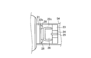
- FIG. 7 is a view showing a cross section B-B 'in FIG.
- FIG. 8 is a view on arrow C in FIG. FIG.
- FIG. 9 is a side view showing the positional relationship between the outer column and the inner column when the telescopic position of the steering wheel is most toward the front.
- FIG. 10 is a side view showing the operation of the stopper when a primary collision occurs.
- FIG. 11 is a side view showing the operation of the outer column when a secondary collision occurs.
- FIG. 1 is a block diagram of an electric power steering apparatus provided with an electric motor according to the present embodiment.
- FIG. 2 is a side view schematically showing the periphery of the steering column.
- FIG. 3 is a plan view schematically showing a portion for attaching the steering column to the vehicle.
- FIG. 4 is a perspective view schematically showing a portion for attaching the steering column to a vehicle.
- the outline of the steering apparatus according to the present embodiment will be described by taking the electric power steering apparatus 80 as an example with reference to FIGS. 1 to 4.
- the front of the vehicle when the electric power steering apparatus 80 is attached to the vehicle is simply described as the front, and the rear of the vehicle when the electric power steering apparatus 80 is attached to the vehicle is simply the rear. be written.
- the front is the left side in the figure
- the rear is the right side in the figure.
- the electric power steering apparatus 80 includes a steering wheel 81, a steering shaft 82, a steering force assist mechanism 83, a universal joint 84, a lower shaft 85, and a universal joint 86 in the order of transmission of the force applied by the operator.
- a pinion shaft 87, a steering gear 88, and a tie rod 89 are provided.
- the electric power steering apparatus 80 includes an ECU (Electronic Control Unit) 90 and a torque sensor 91a.
- the vehicle speed sensor 91 b is provided in the vehicle, and inputs a vehicle speed signal V to the ECU 90 by CAN (Controller Area Network) communication.
- the steering shaft 82 includes an input shaft 82a and an output shaft 82b.
- One end of the input shaft 82a is connected to the steering wheel 81, and the other end is connected to the steering force assist mechanism 83 via a torque sensor 91a.
- One end of the output shaft 82 b is connected to the steering force assist mechanism 83, and the other end is connected to the universal joint 84.
- the input shaft 82a and the output shaft 82b are formed of a magnetic material such as iron.
- the lower shaft 85 is connected at one end to the universal joint 84 and at the other end to the universal joint 86.
- One end of the pinion shaft 87 is connected to the universal joint 86, and the other end is connected to the steering gear 88.
- the steering gear 88 includes a pinion 88a and a rack 88b.
- the pinion 88 a is coupled to the pinion shaft 87.
- the rack 88 b meshes with the pinion 88 a.
- the steering gear 88 is configured as a rack and pinion type.
- the steering gear 88 converts the rotational motion transmitted to the pinion 88a into a linear motion at the rack 88b.
- the tie rods 89 are connected to the rack 88 b.
- the steering force assist mechanism 83 includes a reduction gear 92 and an electric motor (motor) 70.
- the electric motor 70 will be described by exemplifying a so-called brushless motor, but may be an electric motor provided with a brush (slider) and a commutator.
- the reduction gear 92 is connected to the output shaft 82b.
- the electric motor 70 is a motor connected to the reduction gear 92 and generating an assist steering torque.
- a steering column is configured by the steering shaft 82, the torque sensor 91a, and the reduction gear 92.
- the electric motor 70 applies an auxiliary steering torque to the output shaft 82b of the steering column. That is, the electric power steering apparatus 80 of the present embodiment is a column assist system.
- the steering force assist mechanism 83 of the electric power steering apparatus 80 supports a steering column 50 and a steering bracket 52 called an upper mounting bracket as a mechanism for supporting the ECU 90, the electric motor 70, and other components.
- the steering bracket 52 and the steering column 50 rotatably support the input shaft 82a.
- the steering column 50 has a double-pipe structure including an outer column 51 and an inner column 54, which absorb impact energy at the time of collapse in a connecting portion with the reduction gear 92 to secure a predetermined collapse stroke.
- the steering bracket 52 is disposed above the outer column 51 in the vertical direction.
- the steering bracket 52 is attached to the vehicle body and supports the outer column 51.
- the steering bracket 52 includes an attachment plate 52b attached to a vehicle body side member (not shown), a frame-like support 52a integrally formed with the attachment plate 52b, and a tilt mechanism for supporting the outer column 51; Is equipped.
- the mounting plate portion 52 b of the steering bracket 52 is provided with a capsule support portion 59 which spreads on both sides centering on the outer column 51.
- the tilt mechanism is formed on the frame-like support 52a.
- the mounting plate portion 52b of the steering bracket 52 has a pair of left and right detachment capsules 11 attached to the vehicle body side member, and a capsule support part 59 fixed to the detachment capsule 11 by the resin member 12p formed by resin injection. .
- the release capsule 11 is formed by die-casting aluminum.
- the release capsule 11 has a capsule mounting hole 11 h and is fixed to the vehicle body side member by a bolt or the like inserted into the capsule mounting hole 11 h.
- the tilt lever 53 of the tilt mechanism By turning the tilt lever 53 of the tilt mechanism, the tightening force on the frame-like support 52a is released and the support state is released. By this operation, the tilt position of the steering column 50 can be adjusted up and down. Adjustment of the telescopic position described later is also possible by rotating the tilt lever 53.
- the torque sensor 91 a shown in FIG. 1 detects the steering force of the driver transmitted to the input shaft 82 a via the steering wheel 81 as a steering torque.
- the vehicle speed sensor 91 b detects the traveling speed (vehicle speed) of the vehicle on which the electric power steering apparatus 80 is mounted.
- the ECU 90 is electrically connected to the electric motor 70, the torque sensor 91a, and the vehicle speed sensor 91b.
- the ECU 90 controls the operation of the electric motor 70. Further, the ECU 90 obtains signals from each of the torque sensor 91a and the vehicle speed sensor 91b. That is, the ECU 90 acquires the steering torque T from the torque sensor 91a, and acquires the vehicle speed signal V of the vehicle from the vehicle speed sensor 91b.
- the ECU 90 is supplied with power from a power supply device (for example, an on-board battery) 99 while the ignition switch 98 is on.
- the ECU 90 calculates an assist steering command value of the assist command based on the steering torque T and the vehicle speed signal V. Then, the ECU 90 adjusts the power value X supplied to the electric motor 70 based on the calculated assist steering command value.
- the ECU 90 acquires information on the induced voltage or information on the rotation of a rotor such as a resolver to be described later from the electric motor 70 as operation information Y.
- the steering force of the operator (driver) input to the steering wheel 81 is transmitted to the reduction gear 92 of the steering force assist mechanism 83 via the input shaft 82a.
- the ECU 90 acquires the steering torque T input to the input shaft 82a from the torque sensor 91a, and acquires the vehicle speed signal V from the vehicle speed sensor 91b. Then, the ECU 90 controls the operation of the electric motor 70.
- the assist steering torque generated by the electric motor 70 is transmitted to the reduction gear 92.
- the steering torque (including the auxiliary steering torque) output via the output shaft 82 b is transmitted to the lower shaft 85 via the universal joint 84 and further transmitted to the pinion shaft 87 via the universal joint 86.
- the steering force transmitted to the pinion shaft 87 is transmitted to the tie rod 89 via the steering gear 88 to steer the steered wheels.
- FIG. 5 is a view showing a cross section AA 'in FIG.
- FIG. 6 is a side view showing the inner column inserted into the outer column.
- the cylindrical outer column 51 has two telescopic adjustment units 31 and a slit 51 s.
- the telescopic adjustment portion 31 is a portion that protrudes outward in the radial direction from the outer peripheral surface of the outer column 51, and has an axial long hole 32 whose longitudinal direction is along the axial direction as shown in FIG.
- the radial direction is a direction orthogonal to the axial direction of the outer column 51, and the same meaning is used in the following description.
- the respective axial elongated holes 32 included in the two telescopic adjustment units 31 are opposed in the direction orthogonal to the axial direction.
- a rod 33 passes through the axially elongated hole 32.
- the rod 33 penetrates the axial long hole 32 and penetrates the frame-like support 52 a and is connected to the tilt lever 53.
- the slits 51s are provided on the outer peripheral surface of the outer column 51, and are long holes whose longitudinal direction is along the axial direction.
- the inner column 54 is a cylindrical member which is partially inserted into the outer column 51 and guides the outer column 51 in the axial direction.
- the outer diameter of the inner column 54 is substantially equal to the inner diameter of the outer column 51. Therefore, when the outer column 51 covers the inner column 54, the inner peripheral surface of the outer column 51 and the outer peripheral surface of the inner column 54 are in contact at the time of tightening. Further, since the outer column 51 includes the telescopic adjustment portion 31 having the axially elongated hole 32, the outer column 51 can slide relative to the inner column 54 in the range of the length of the axially elongated hole 32. For example, at the time of tightening, the frictional force when the outer column 51 slides is set to 500N to 600N. Therefore, the possibility of the outer column 51 sliding due to the force applied by the operator to the steering wheel 81 at the time of driving is low.
- the tilt lever 53 When the tilt lever 53 is rotated, the tightening force with respect to the frame-like support 52a decreases, so the width of the slit 51s of the outer column 51 increases. As a result, the force with which the outer column 51 clamps the inner column 54 is eliminated, so that the frictional force when the outer column 51 slides is eliminated.
- the operator can adjust the telescopic position by pushing and pulling the outer column 51 via the steering wheel 81 after rotating the tilt lever 53.
- FIG. 7 is a view showing a cross section BB ′ in FIG.
- FIG. 8 is a view on arrow C in FIG.
- the inner column 54 has a stopper 2 on the outer peripheral surface.
- the stopper 2 is disposed below the inner column 54 in the vertical direction.
- the stopper 2 is a member that regulates the range in which the outer column 51 can move in the axial direction, and includes a base portion 21, a first arm 22, a hold portion 23, a second arm 24, and a weight 29.
- the position at which the stopper 2 is disposed does not have to be on the lower side of the inner column 54 in the vertical direction, and may be, for example, on the upper side in the vertical direction or another position in the circumferential direction.
- the base portion 21 is a member provided so as to protrude radially outward from the outer peripheral surface of the inner column 54.
- the base portion 21 is formed of, for example, a synthetic resin or an aluminum alloy, and is fixed to the lower side in the vertical direction of the outer peripheral surface of the inner column 54 by welding.
- the first arm 22 is a member having one end fixed to the base portion 21 and provided from the base portion 21 in the axial direction.
- the first arm 22 has a fixed portion 22b provided at an end portion on the base portion 21 side, and a deformed portion 22c which is provided toward the rear side from the fixed portion 22b and a portion thereof is shaped along the outer peripheral surface of the inner column 54.
- the first arm 22 is made of, for example, a ductile aluminum alloy or synthetic resin, and is fixed to the base portion 21 by the bolt 28 at the fixing portion 22 b. As shown in FIG. 8, the circumferentially central portion of the deformation portion 22c is formed to be thin.
- the shape of the deformation portion 22c is not limited to the above-described shape, and may be a shape that can undergo predetermined elastic deformation when a primary collision described later occurs.
- the holding part 23 is, for example, a semi-cylindrical member having an outer diameter substantially equal to the outer diameter of the outer column 51.
- the holding portion 23 is made of, for example, a synthetic resin or an aluminum alloy, and is provided at the rear end of the first arm 22.
- the second arm 24 is a member whose one end is fixed to the holding portion 23 and provided radially outward from the holding portion 23.
- the second arm 24 is formed of, for example, a synthetic resin or an aluminum alloy, and is provided at the circumferential center of the outer peripheral surface of the holding portion 23.
- the second arm 24 is plate-like, and is disposed such that the two largest surfaces are directed forward and backward.
- the second arm 24 has a reinforcing plate 25 provided on the surface facing rearward.
- the reinforcing plate 25 is made of, for example, a synthetic resin or an aluminum alloy.
- the largest area of the reinforcing plate 25 is orthogonal to the largest area of the second arm 24. That is, the reinforcing plate 25 is fixed so that the second arm 24 and the reinforcing plate 25 form a substantially T-shape. Thereby, even when a force is applied to the second arm 24, the second arm 24 is less likely to be deformed.
- the weight 29 includes, for example, an outer weight 26 which is a cylindrical member in which a part of a side surface is opened, and an inner weight 27 housed inside the outer weight 26.
- the outer weight 26 is made of, for example, a synthetic resin or an aluminum alloy, and is provided at the end of the second arm 24 opposite to the holding portion 23. The length of the second arm 24 is adjusted so that the outer weight 26 is located radially outward of the base portion 21.
- the inner weight 27 is made of, for example, iron.
- the outer weight 26 is partially cut away in the side surface and has an opening, so the inner diameter can be adjusted by widening the width of the opening. For this reason, the outer weight 26 can adjust the volume of the inner weight 27 accommodated inside.
- the weight 29 can be adjusted in weight by adjusting the volume or the material of the inner weight 27.
- the outer weight 26 and the inner weight 27 may be integrally formed.
- FIG. 9 is a side view showing the positional relationship between the outer column and the inner column when the telescopic position of the steering wheel is most toward the front.
- the rear end of the axially elongated hole 32 of the telescopic adjustment unit 31 contacts the rod 33. Since the longitudinal position of the rod 33 is fixed, the longitudinal movement of the outer column 51 is restricted by the rod 33. Further, when the telescopic position of the steering wheel 81 is closest to the front, the front end face 51 a of the outer column 51 contacts the rear end face 23 a of the holding portion 23. Thus, the movement of the outer column 51 in the front-rear direction is restricted by the stopper 2.
- the electric power steering apparatus 80 can suppress a malfunction in normal use.
- the normal use also includes a state in which inertia or impact is applied by acceleration and deceleration during operation.
- FIG. 10 is a side view showing the operation of the stopper when a primary collision occurs.
- the primary collision is that a running vehicle collides with another vehicle or the like in a collision accident.
- the stopper 2 is deformed by inertial force.
- forward inertia force is applied to the vehicle, and therefore forward inertia force is applied to the weight 29 of the stopper 2.
- the forward inertial force applied to the weight 29 is a force that pulls the holding portion 23 downward via the second arm 24.
- the downward force applied to the holding unit 23 moves the holding unit 23 downward. As the holding unit 23 moves downward, a downward force is applied to the end of the first arm 22 on the holding unit 23 side.
- the first arm 22 is deformed so that the end of the holding unit 23 moves downward with the end of the base 21 as a supporting point.
- the hold section 23 and the hold section 23 side end of the first arm 22 are separated from the outer circumferential surface of the inner column 54, so the column side surface 22 a which is the surface of the first arm 22 on the inner column 54 is the inner column 54. It inclines to the outer peripheral surface of.
- the stopper 2 is deformed due to an inertial force, the hold portion 23 is separated radially outward from the outer peripheral surface of the inner column 54, so that the range in which the outer column 51 can move in the axial direction can be expanded. .
- the amount of deformation of the stopper 2 due to the inertial force can be easily adjusted by adjusting the rigidity of the first arm 22, the length of the second arm 24, the weight of the weight 29, and the like.
- the electric power steering device 80 can appropriately adjust the amount of deformation of the stopper 2 in normal use, it is possible to suppress a malfunction in normal use.
- the stopper 2 may not have a structure that causes deformation when an inertial force acts.
- the stopper 2 may expand a range in which the outer column 51 can move in the axial direction by partially breaking when an inertial force acts. For example, when the material, shape, etc. are adjusted so that the first arm 22 breaks when an inertial force acts, the hold unit 23 falls, so the stopper 2 can move the outer column 51 in the axial direction Can be enlarged.
- FIG. 11 is a side view showing the operation of the outer column when a secondary collision occurs.
- the secondary collision is that the body of the operator collides with the steering wheel 81 or the like in a collision accident.
- the telescopic position of the steering wheel 81 is not at the frontmost position before the occurrence of the primary collision.
- forward force is applied to the outer column 51 via the steering wheel 81.
- the force applied to the outer column 51 at the time of the secondary collision is larger than the frictional force when the outer column 51 slides on the inner column 54. Therefore, the outer column 51 moves forward while absorbing an impact by friction with the inner column 54.
- the outer column 51 moves forward until the rod 33 reaches the rear end of the axial long hole 32.
- the timing at which the secondary collision occurs is immediately after the timing at which the primary collision occurs. For this reason, when a secondary collision occurs, as shown in FIG. 11, the hold portion 23 remains separated from the outer peripheral surface of the inner column 54. Thereby, the range in which the outer column 51 can move in the axial direction is expanded compared to that in normal use.
- the outer column 51 can move axially beyond the range that can be moved during normal use. Therefore, the outer column 51 can move forward while the rod 33 is in contact with the rear end of the axial long hole 32. For this reason, while the outer column 51 is moving forward, the load applied to the outer column 51 is not transmitted to the stopper 2, and is released via the rod 33 and the frame-like support 52a shown in FIG. It is transmitted to the capsule 11. For this reason, the detachment capsule 11 is broken.
- the outer column 51 can move forward without being restricted by the rod 33.
- the outer column 51 can move forward beyond the position where the holding unit 23 was before the primary collision. Therefore, the outer column 51 can move forward while absorbing an impact by friction with the inner column 54. Thereby, the electric power steering device 80 can reduce the impact applied to the operator at the time of the secondary collision.
- the stopper 2 When the outer column 51 moves forward, the stopper 2 is deformed so that the column side surface 22a of the first arm 22 is inclined.
- the front end face 51 a of the outer column 51 contacts the column side surface 22 a of the first arm 22. Since the column side surface 22a is inclined with respect to the outer peripheral surface of the inner column 54, part of the force for moving the outer column 51 forward is converted into a force that pushes the column side surface 22a downward.
- the deformation portion 22c When the column side surface 22a is pushed downward, the deformation portion 22c is further deformed. Thereby, the outer column 51 moves forward while further deforming the deformation portion 22c. Also, friction occurs between the front end face 51 a of the outer column 51 and the column side surface 22 a.
- the force for moving the outer column 51 forward is gradually reduced by being consumed by the deformation of the deformation portion 22c and the friction between the end face 51a and the column side surface 22a.
- the stopper 2 can absorb the impact applied to the outer column 51. Therefore, the electric power steering device 80 according to the present embodiment can easily reduce the impact applied to the operator at the time of the secondary collision.
- the electric power steering apparatus 80 includes the input shaft 82a whose one end is connected to the steering wheel 81, and the steering column 50 which rotatably supports the input shaft 82a.
- the steering column 50 has a cylindrical outer column 51 and a cylindrical inner column 54 which is partially inserted into the outer column 51 and guides the outer column 51 in the axial direction.
- the inner column 54 has a stopper 2 on the outer peripheral surface that limits the range in which the outer column 51 can move in the axial direction, and the stopper 2 enlarges the range when deformation or movement occurs due to inertia force.
- the stopper 2 when the primary collision occurs, the stopper 2 is deformed or moved by the inertia force, and the range in which the outer column 51 can move in the axial direction is expanded.
- the outer column 51 when a secondary collision occurs after the primary collision, the outer column 51 can move axially beyond the range of axial movement in normal use.
- the force applied to the outer column 51 contacts the rod 33 at the rear end of the axial elongated hole 32 and is transmitted to the steering bracket 52 via the rod 33 to be transmitted to the disengaging capsule 11 as a support structure.
- the breakaway capsule 11 is broken and the steering column 50 is moved forward of the vehicle.
- the stopper 2 together with the axial direction elongated hole 32 of the outer column 54 restricts the movable range of the outer column 54 in the axial direction.
- the excessive load is transmitted forward through the outer column 51, the stopper 2 and the inner column 54, so that the force is not easily transmitted to the detachment capsule 11. .
- the set value of the detachment load of the detachment capsule 11 is lowered, the situation where the detachment capsule 11 breaks in normal use is suppressed. Therefore, in the electric power steering apparatus 80 according to the present embodiment, even if the setting value of the separation load at which the steering column 50 moves in the forward direction of the vehicle is lowered while part of the support structure is cut, malfunction is suppressed in normal use. Can.
- the stopper 2 is provided with the weight 29 and the outer column 51 is in the axial direction when the stopper 2 is deformed or moved by the inertia force applied to the weight 29 at the primary collision. Expand the range of movement.
- the amount of deformation or movement of the stopper 2 at the time of the primary collision can be easily adjusted.
- the electric power steering device 80 can appropriately adjust the amount of deformation of the stopper 2 and thus can suppress a malfunction in normal use.
- the stopper 2 has one end fixed to the base portion 21 fixed to the outer peripheral surface of the inner column 54 and the base portion 21.
- a first arm 22 provided, a hold unit 23 fixed to the other end of the first arm 22, and a second arm 24 fixed at one end to the hold unit 23 and provided radially outward from the hold unit 23; And a weight 29 fixed to the other end of the second arm 24.
- an inertial force is applied to the weight 29 of the stopper 2.
- the inertial force applied to the weight 29 is a force that pulls the holding portion 23 outward in the radial direction of the inner column 54 via the second arm 24.
- the radially outward force applied to the hold portion 23 moves the hold portion 23 radially outward.
- a radially outward force is applied to the end portion of the first arm 22 on the side of the hold portion 23.
- the first arm 22 is deformed such that the end portion on the side of the holding portion 23 moves radially outward with the end portion on the side of the base portion 21 as a supporting point.
- the column side surface 22a which is the surface on the inner column 54 side of the first arm 22, is inclined.
- the column side surface 22 a is inclined with respect to the outer peripheral surface of the inner column 54.
- the electric power steering device 80 can easily reduce the impact applied to the operator at the time of the secondary collision.
- the electric power steering apparatus 80 includes a steering bracket 52 that clamps and supports the outer column 51, and a detachment capsule 11 that detachably secures the steering bracket 52 to the vehicle body.
- the steering bracket 52 is separated from the vehicle body at the time of a secondary collision, whereby the movable range of the outer column 54 in the axial direction is further expanded.
- the outer column 51 can slide relative to the inner column 54 when the tightening of the steering bracket 52 is released.
- the inner peripheral surface of the outer column 51 and the outer peripheral surface of the inner column 54 are in contact, and when a secondary collision occurs, the outer column 51 absorbs the impact by friction with the inner column 54 Moving.
- the electric power steering device 80 can reduce the impact applied to the operator at the time of the secondary collision.
- the base portion 21 of the stopper 2 may not necessarily be fixed to the outer peripheral surface of the inner column 54.
- the base portion 21 may be fixed to the reduction gear 92 connected to the inner column 54. More specifically, as shown in FIG. 2, the base portion 21 may be fixed to the adjacent reduction gear 92 by welding or the like.
Landscapes
- Engineering & Computer Science (AREA)
- Chemical & Material Sciences (AREA)
- Combustion & Propulsion (AREA)
- Transportation (AREA)
- Mechanical Engineering (AREA)
- Steering Controls (AREA)
Abstract
Description
図1は、本実施形態に係る電動モータを備える電動パワーステアリング装置の構成図である。図2は、ステアリングコラムの周囲を模式的に示す側面図である。図3は、ステアリングコラムを車両に取り付ける部分を模式的に示す平面図である。図4は、ステアリングコラムを車両に取り付ける部分を模式的に示す斜視図である。図1から図4を用いて、本実施形態に係るステアリング装置として電動パワーステアリング装置80を例に挙げて概要を説明する。また、以下の説明において、電動パワーステアリング装置80を車両に取り付けた場合の車両の前方は、単に前方と記載され、電動パワーステアリング装置80を車両に取り付けた場合の車両の後方は、単に後方と記載される。図2において、前方は、図中の左側であり、後方は、図中の右側である。
電動パワーステアリング装置80は、操作者から与えられる力が伝達する順に、ステアリングホイール81と、ステアリングシャフト82と、操舵力アシスト機構83と、ユニバーサルジョイント84と、ロアシャフト85と、ユニバーサルジョイント86と、ピニオンシャフト87と、ステアリングギヤ88と、タイロッド89とを備える。また、電動パワーステアリング装置80は、ECU(Electronic Control Unit)90と、トルクセンサ91aとを備える。車速センサ91bは、車両に備えられ、CAN(Controller Area Network)通信により車速信号VをECU90に入力する。
ECU90は、電動モータ70の動作を制御する。また、ECU90は、トルクセンサ91a及び車速センサ91bのそれぞれから信号を取得する。すなわち、ECU90は、トルクセンサ91aから操舵トルクTを取得し、かつ、車速センサ91bから車両の車速信号Vを取得する。ECU90は、イグニッションスイッチ98がオンの状態で、電源装置(例えば車載のバッテリ)99から電力が供給される。ECU90は、操舵トルクTと車速信号Vとに基づいてアシスト指令の補助操舵指令値を算出する。そして、ECU90は、その算出された補助操舵指令値に基づいて電動モータ70へ供給する電力値Xを調節する。ECU90は、電動モータ70から誘起電圧の情報または後述するレゾルバ等のロータの回転の情報を動作情報Yとして取得する。
図5は、図2におけるA-A’断面を示す図である。図6は、アウターコラムに挿入されるインナーコラムを示す側面図である。図5に示すように、筒状のアウターコラム51は、2つのテレスコ調整部31と、スリット51sと、を有する。テレスコ調整部31は、アウターコラム51の外周面から径方向外側に突出する部分であり、図6に示すように長手方向が軸方向に沿っている軸方向長孔32を有する。径方向は、アウターコラム51の軸方向に対して直交する方向であり、以下の説明においても同様の意味で用いられる。2つのテレスコ調整部31が有するそれぞれの軸方向長孔32は、軸方向に対して直交方向に対向している。軸方向長孔32には、ロッド33が貫通している。ロッド33は、軸方向長孔32を貫通するとともに枠状支持部52aを貫通し、チルトレバー53と連結されている。また、スリット51sは、アウターコラム51の外周面に設けられており、長手方向が軸方向に沿っている長孔である。
図7は、図6におけるB-B’断面を示す図である。図8は、図6におけるC矢視図である。図6、図7および図8に示すように、インナーコラム54は、外周面にストッパー2を有する。例えば、ストッパー2は、インナーコラム54の鉛直方向下側に配置されている。ストッパー2は、アウターコラム51が軸方向に動ける範囲を規制する部材であり、ベース部21と、第1アーム22と、ホールド部23と、第2アーム24と、ウェイト29と、を有する。なお、ストッパー2が配置される位置は、インナーコラム54の鉛直方向下側でなくてもよく、例えば鉛直方向上側でもよいし、周方向のその他の位置であってもよい。
11h カプセル取付孔
12p 樹脂部材
2 ストッパー
21 ベース部
22 第1アーム
22a コラム側表面
22b 固定部
22c 変形部
23 ホールド部
23a 端面
24 第2アーム
25 補強板
26 アウターウェイト
27 インナーウェイト
28 ボルト
29 ウェイト
31 テレスコ調整部
32 軸方向長孔
33 ロッド
50 ステアリングコラム
51 アウターコラム
51s スリット
52 ステアリング用ブラケット
52a 枠状支持部
52b 取付板部
53 チルトレバー
54 インナーコラム
59 カプセル支持部
70 電動モータ
80 電動パワーステアリング装置
81 ステアリングホイール
82 ステアリングシャフト
82a 入力軸
82b 出力軸
83 操舵力アシスト機構
84 ユニバーサルジョイント
85 ロアシャフト
86 ユニバーサルジョイント
87 ピニオンシャフト
88 ステアリングギヤ
88a ピニオン
88b ラック
89 タイロッド
90 ECU
91a トルクセンサ
91b 車速センサ
92 減速装置
98 イグニッションスイッチ
99 電源装置
Claims (6)
- 一方の端部がステアリングホイールに連結される入力軸と、
前記入力軸を回転可能に支持するステアリングコラムと、
を備え、
前記ステアリングコラムは、筒状のアウターコラムと、一部が前記アウターコラムに挿入され前記アウターコラムを軸方向に案内する筒状のインナーコラムとを有し、
前記インナーコラムは、前記アウターコラムが軸方向に動ける範囲を規制するストッパーを外周面に有し、
前記ストッパーは、慣性力による変形または移動が生じた場合に前記範囲を拡大させるステアリング装置。 - 前記ストッパーはウェイトを備え、
1次衝突時に前記ウェイトに加わる慣性力により前記ストッパーに変形または移動が生じた場合に前記範囲を拡大させる請求項1に記載のステアリング装置。 - 前記ストッパーは、前記インナーコラムの外周面に固定されたベース部と、前記ベース部に一端が固定され前記ベース部から軸方向に向かって設けられる第1アームと、前記第1アームの他端に固定されるホールド部と、前記ホールド部に一端が固定され前記ホールド部から径方向外側に向かって設けられる第2アームと、前記第2アームの他端に固定される前記ウェイトと、を有する請求項2に記載のステアリング装置。
- 前記インナーコラムに連結される減速装置を備え、
前記ストッパーは、前記減速装置に固定されたベース部と、前記ベース部に一端が固定され前記ベース部から軸方向に向かって設けられる第1アームと、前記第1アームの他端に固定されるホールド部と、前記ホールド部に一端が固定され前記ホールド部から径方向外側に向かって設けられる第2アームと、前記第2アームの他端に固定される前記ウェイトと、を有する請求項2に記載のステアリング装置。 - 前記アウターコラムを締め付けて支持するステアリング用ブラケットと、
前記ステアリング用ブラケットを車体に離脱可能に固定する離脱カプセルと、
を備える請求項1~4のいずれか1項に記載のステアリング装置。 - 前記ステアリング用ブラケットの締め付けが解除されたとき、前記アウターコラムは前記インナーコラムに対して摺動可能であり、
前記ステアリング用ブラケットの締め付け時には前記アウターコラムの内周面と前記インナーコラムの外周面とが接触しており、2次衝突が生じると前記アウターコラムは前記インナーコラムとの摩擦によって衝撃を吸収しながら移動する請求項5に記載のステアリング装置。
Priority Applications (4)
| Application Number | Priority Date | Filing Date | Title |
|---|---|---|---|
| EP14863229.2A EP2995530B1 (en) | 2013-11-20 | 2014-11-17 | Steering device |
| JP2015549138A JP5871110B2 (ja) | 2013-11-20 | 2014-11-17 | ステアリング装置 |
| CN201480045687.9A CN105473415B (zh) | 2013-11-20 | 2014-11-17 | 转向装置 |
| US14/764,255 US9393987B2 (en) | 2013-11-20 | 2014-11-17 | Steering apparatus |
Applications Claiming Priority (2)
| Application Number | Priority Date | Filing Date | Title |
|---|---|---|---|
| JP2013-240261 | 2013-11-20 | ||
| JP2013240261 | 2013-11-20 |
Publications (1)
| Publication Number | Publication Date |
|---|---|
| WO2015076226A1 true WO2015076226A1 (ja) | 2015-05-28 |
Family
ID=53179488
Family Applications (1)
| Application Number | Title | Priority Date | Filing Date |
|---|---|---|---|
| PCT/JP2014/080390 WO2015076226A1 (ja) | 2013-11-20 | 2014-11-17 | ステアリング装置 |
Country Status (5)
| Country | Link |
|---|---|
| US (1) | US9393987B2 (ja) |
| EP (1) | EP2995530B1 (ja) |
| JP (1) | JP5871110B2 (ja) |
| CN (1) | CN105473415B (ja) |
| WO (1) | WO2015076226A1 (ja) |
Cited By (2)
| Publication number | Priority date | Publication date | Assignee | Title |
|---|---|---|---|---|
| DE102015225907A1 (de) * | 2015-12-18 | 2017-06-22 | Thyssenkrupp Ag | Lenksäule für ein Kraftfahrzeug |
| CN112429073A (zh) * | 2020-11-27 | 2021-03-02 | 东风柳州汽车有限公司 | 一种转向管柱组件 |
Citations (13)
| Publication number | Priority date | Publication date | Assignee | Title |
|---|---|---|---|---|
| US3791233A (en) * | 1972-11-06 | 1974-02-12 | Volvo Ab | Collapsible vehicle-steering systems |
| JPS49116738A (ja) * | 1973-03-12 | 1974-11-07 | ||
| JPS5178533U (ja) * | 1974-12-17 | 1976-06-21 | ||
| JPS51115319U (ja) * | 1975-03-14 | 1976-09-18 | ||
| JPS5424431Y2 (ja) * | 1974-12-19 | 1979-08-18 | ||
| JPS6319467U (ja) | 1986-07-24 | 1988-02-08 | ||
| JPH0781586A (ja) | 1993-07-20 | 1995-03-28 | Toyota Motor Corp | ステアリング装置 |
| JP2003002211A (ja) * | 2001-06-27 | 2003-01-08 | Koyo Seiko Co Ltd | 衝撃吸収ステアリング装置 |
| JP2004017908A (ja) * | 2002-06-19 | 2004-01-22 | Nsk Ltd | 車両用衝撃吸収式ステアリングコラム装置 |
| JP2005001517A (ja) * | 2003-06-12 | 2005-01-06 | Nsk Ltd | ステアリング装置 |
| JP2005138758A (ja) * | 2003-11-07 | 2005-06-02 | Nsk Ltd | 車両用テレスコピック式ステアリング装置 |
| JP2005343189A (ja) * | 2004-05-31 | 2005-12-15 | Koyo Seiko Co Ltd | 衝撃吸収式ステアリング装置 |
| JP2010241321A (ja) * | 2009-04-08 | 2010-10-28 | Toyota Motor Corp | ステアリングコラム装置 |
Family Cites Families (15)
| Publication number | Priority date | Publication date | Assignee | Title |
|---|---|---|---|---|
| FR2696145B1 (fr) * | 1992-09-28 | 1994-12-30 | Ecia Equip Composants Ind Auto | Ensemble de colonne de direction réglable en position pour véhicule automobile. |
| JP3440605B2 (ja) * | 1995-02-27 | 2003-08-25 | 日本精工株式会社 | チルト式ステアリング装置 |
| US5715730A (en) * | 1996-06-10 | 1998-02-10 | General Motors Corporation | Tilt adjustable motor vehicle steering column |
| JP3064912B2 (ja) * | 1996-07-02 | 2000-07-12 | 富士機工株式会社 | 車両用ステアリングコラム |
| DE19631214C2 (de) * | 1996-08-02 | 1998-06-10 | Mc Micro Compact Car Ag | Lenksäule für ein Kraftfahrzeug |
| US5803496A (en) * | 1997-03-31 | 1998-09-08 | General Motors Corporation | Energy-absorbing steering column for motor vehicle |
| DE602004009678T2 (de) * | 2003-05-14 | 2008-08-07 | Toyota Jidosha Kabushiki Kaisha, Toyota | Stossdämpfungs-lenkvorrichtung |
| US7178833B2 (en) * | 2004-03-15 | 2007-02-20 | Delphi Technologies, Inc. | Steering column assembly with vertical capsules |
| SE533685C2 (sv) * | 2009-04-08 | 2010-11-30 | Scania Cv Ab | Justerbar styranordning med mekaniskt minne |
| WO2010122958A1 (ja) * | 2009-04-20 | 2010-10-28 | 日本精工株式会社 | ステアリングホイールの位置調節装置 |
| DE102010036894A1 (de) * | 2010-05-25 | 2011-12-01 | Thyssenkrupp Presta Ag | Federkörper |
| CN102438878B (zh) * | 2010-08-06 | 2015-02-25 | 日本精工株式会社 | 冲击吸收式转向装置 |
| JP5620841B2 (ja) * | 2011-02-04 | 2014-11-05 | 株式会社山田製作所 | ステアリング装置 |
| JP5912970B2 (ja) * | 2012-07-28 | 2016-04-27 | 株式会社山田製作所 | ステアリング装置 |
| JP5856204B2 (ja) * | 2014-02-19 | 2016-02-09 | 株式会社山田製作所 | ステアリング装置 |
-
2014
- 2014-11-17 US US14/764,255 patent/US9393987B2/en active Active
- 2014-11-17 EP EP14863229.2A patent/EP2995530B1/en active Active
- 2014-11-17 CN CN201480045687.9A patent/CN105473415B/zh active Active
- 2014-11-17 WO PCT/JP2014/080390 patent/WO2015076226A1/ja active Application Filing
- 2014-11-17 JP JP2015549138A patent/JP5871110B2/ja active Active
Patent Citations (13)
| Publication number | Priority date | Publication date | Assignee | Title |
|---|---|---|---|---|
| US3791233A (en) * | 1972-11-06 | 1974-02-12 | Volvo Ab | Collapsible vehicle-steering systems |
| JPS49116738A (ja) * | 1973-03-12 | 1974-11-07 | ||
| JPS5178533U (ja) * | 1974-12-17 | 1976-06-21 | ||
| JPS5424431Y2 (ja) * | 1974-12-19 | 1979-08-18 | ||
| JPS51115319U (ja) * | 1975-03-14 | 1976-09-18 | ||
| JPS6319467U (ja) | 1986-07-24 | 1988-02-08 | ||
| JPH0781586A (ja) | 1993-07-20 | 1995-03-28 | Toyota Motor Corp | ステアリング装置 |
| JP2003002211A (ja) * | 2001-06-27 | 2003-01-08 | Koyo Seiko Co Ltd | 衝撃吸収ステアリング装置 |
| JP2004017908A (ja) * | 2002-06-19 | 2004-01-22 | Nsk Ltd | 車両用衝撃吸収式ステアリングコラム装置 |
| JP2005001517A (ja) * | 2003-06-12 | 2005-01-06 | Nsk Ltd | ステアリング装置 |
| JP2005138758A (ja) * | 2003-11-07 | 2005-06-02 | Nsk Ltd | 車両用テレスコピック式ステアリング装置 |
| JP2005343189A (ja) * | 2004-05-31 | 2005-12-15 | Koyo Seiko Co Ltd | 衝撃吸収式ステアリング装置 |
| JP2010241321A (ja) * | 2009-04-08 | 2010-10-28 | Toyota Motor Corp | ステアリングコラム装置 |
Non-Patent Citations (1)
| Title |
|---|
| See also references of EP2995530A4 |
Cited By (5)
| Publication number | Priority date | Publication date | Assignee | Title |
|---|---|---|---|---|
| DE102015225907A1 (de) * | 2015-12-18 | 2017-06-22 | Thyssenkrupp Ag | Lenksäule für ein Kraftfahrzeug |
| US10611398B2 (en) | 2015-12-18 | 2020-04-07 | Thyssenkrupp Presta Ag | Steering column for a motor vehicle |
| EP3390201B1 (de) * | 2015-12-18 | 2021-02-03 | thyssenkrupp Presta AG | Lenksäule für ein kraftfahrzeug |
| CN112429073A (zh) * | 2020-11-27 | 2021-03-02 | 东风柳州汽车有限公司 | 一种转向管柱组件 |
| CN112429073B (zh) * | 2020-11-27 | 2022-06-07 | 东风柳州汽车有限公司 | 一种转向管柱组件 |
Also Published As
| Publication number | Publication date |
|---|---|
| EP2995530A4 (en) | 2016-11-02 |
| JPWO2015076226A1 (ja) | 2017-03-16 |
| EP2995530A1 (en) | 2016-03-16 |
| JP5871110B2 (ja) | 2016-03-01 |
| US20150367879A1 (en) | 2015-12-24 |
| EP2995530B1 (en) | 2018-02-28 |
| US9393987B2 (en) | 2016-07-19 |
| CN105473415A (zh) | 2016-04-06 |
| CN105473415B (zh) | 2017-04-05 |
Similar Documents
| Publication | Publication Date | Title |
|---|---|---|
| JP4354742B2 (ja) | 車両用ステアリングコラム装置 | |
| EP3009328B1 (en) | Support device for steering bracket, and steering device | |
| WO2015076226A1 (ja) | ステアリング装置 | |
| JP6503882B2 (ja) | ステアリング装置 | |
| JP2008254510A (ja) | ステアリング装置 | |
| JPWO2005005231A1 (ja) | ステアリング装置 | |
| JP5786760B2 (ja) | テレスコピックステアリング装置 | |
| JP6311455B2 (ja) | 電動パワーステアリング装置 | |
| JP5892302B2 (ja) | ステアリング装置 | |
| JP6369046B2 (ja) | ステアリング装置 | |
| JP5218255B2 (ja) | ステアリング装置 | |
| JP6620910B2 (ja) | ステアリング装置 | |
| JP6369045B2 (ja) | ステアリング装置 | |
| JP2017081518A (ja) | ステアリング装置 | |
| JP2007137325A (ja) | 可変舵角操舵装置、自動車、操舵系の収縮方法及び遊星ローラ機構 | |
| JP2015140158A (ja) | ステアリング装置 | |
| JP2017159820A (ja) | ステアリング装置 | |
| JP6623689B2 (ja) | ステアリング装置 | |
| JP6503887B2 (ja) | ステアリング装置 | |
| JP2007137290A (ja) | 衝撃吸収式ステアリングコラム装置 | |
| JP2017144826A (ja) | ステアリング装置 | |
| JP2015180570A (ja) | テレスコピックステアリング装置 | |
| JP2014104782A (ja) | ステアリングコラム用支持装置 |
Legal Events
| Date | Code | Title | Description |
|---|---|---|---|
| WWE | Wipo information: entry into national phase |
Ref document number: 201480045687.9 Country of ref document: CN |
|
| 121 | Ep: the epo has been informed by wipo that ep was designated in this application |
Ref document number: 14863229 Country of ref document: EP Kind code of ref document: A1 |
|
| WWE | Wipo information: entry into national phase |
Ref document number: 14764255 Country of ref document: US |
|
| ENP | Entry into the national phase |
Ref document number: 2015549138 Country of ref document: JP Kind code of ref document: A |
|
| WWE | Wipo information: entry into national phase |
Ref document number: 2014863229 Country of ref document: EP |
|
| NENP | Non-entry into the national phase |
Ref country code: DE |