WO2015075943A1 - ズームレンズ、光学機器、およびズームレンズの製造方法 - Google Patents
ズームレンズ、光学機器、およびズームレンズの製造方法 Download PDFInfo
- Publication number
- WO2015075943A1 WO2015075943A1 PCT/JP2014/005861 JP2014005861W WO2015075943A1 WO 2015075943 A1 WO2015075943 A1 WO 2015075943A1 JP 2014005861 W JP2014005861 W JP 2014005861W WO 2015075943 A1 WO2015075943 A1 WO 2015075943A1
- Authority
- WO
- WIPO (PCT)
- Prior art keywords
- lens group
- lens
- refractive power
- end state
- zoom
- Prior art date
- Legal status (The legal status is an assumption and is not a legal conclusion. Google has not performed a legal analysis and makes no representation as to the accuracy of the status listed.)
- Ceased
Links
Images

Classifications
-
- G—PHYSICS
- G02—OPTICS
- G02B—OPTICAL ELEMENTS, SYSTEMS OR APPARATUS
- G02B15/00—Optical objectives with means for varying the magnification
- G02B15/14—Optical objectives with means for varying the magnification by axial movement of one or more lenses or groups of lenses relative to the image plane for continuously varying the equivalent focal length of the objective
- G02B15/145—Optical objectives with means for varying the magnification by axial movement of one or more lenses or groups of lenses relative to the image plane for continuously varying the equivalent focal length of the objective having five groups only
- G02B15/1451—Optical objectives with means for varying the magnification by axial movement of one or more lenses or groups of lenses relative to the image plane for continuously varying the equivalent focal length of the objective having five groups only the first group being positive
- G02B15/145121—Optical objectives with means for varying the magnification by axial movement of one or more lenses or groups of lenses relative to the image plane for continuously varying the equivalent focal length of the objective having five groups only the first group being positive arranged +-+-+
-
- G—PHYSICS
- G02—OPTICS
- G02B—OPTICAL ELEMENTS, SYSTEMS OR APPARATUS
- G02B27/00—Optical systems or apparatus not provided for by any of the groups G02B1/00 - G02B26/00, G02B30/00
- G02B27/64—Imaging systems using optical elements for stabilisation of the lateral and angular position of the image
- G02B27/646—Imaging systems using optical elements for stabilisation of the lateral and angular position of the image compensating for small deviations, e.g. due to vibration or shake
-
- G—PHYSICS
- G02—OPTICS
- G02B—OPTICAL ELEMENTS, SYSTEMS OR APPARATUS
- G02B5/00—Optical elements other than lenses
- G02B5/005—Diaphragms
Definitions
- the present invention relates to a zoom lens, an optical apparatus, and a zoom lens manufacturing method.
- the present invention has been made in view of such problems, and provides a zoom lens, an optical apparatus, and a method of manufacturing a zoom lens that have a small zoom ratio, a large zoom ratio, and good optical performance.
- the purpose is to do.
- the zoom lens according to the first aspect of the present invention includes a first lens group having a positive refractive power, a second lens group having a negative refractive power, and a positive refraction arranged in order from the object side along the optical axis.
- the fifth lens group, the first lens group, the second lens group, the third lens group, the fourth lens group, and the fifth lens group are optical axes, respectively. The following conditional expression is satisfied.
- f1 the focal length of the first lens group
- ft focal length in the telephoto end state of the zoom lens.
- fw focal length in the wide-angle end state of the zoom lens
- f2 focal length of the second lens group.
- the first lens group preferably includes three positive lenses.
- the first lens group includes a cemented lens of a positive lens and a negative lens and satisfies the following conditional expression.
- nN1 a refractive index with respect to d-line of the negative lens constituting the cemented lens of the first lens group
- nP1 a refractive index with respect to d-line of the positive lens constituting the cemented lens of the first lens group
- ⁇ P1 Abbe number of the positive lens constituting the cemented lens of the first lens group.
- f4 focal length of the fourth lens group.
- the fourth lens group includes a cemented lens of one positive lens and one negative lens.
- an aperture stop is disposed in the vicinity of the object side of the third lens group and the following conditional expression is satisfied.
- ⁇ Zwt a moving distance on the optical axis toward the object side of the aperture stop at the time of zooming from the wide-angle end state to the telephoto end state.
- a zoom lens according to a second aspect of the present invention includes a first lens group having a positive refractive power, a second lens group having a negative refractive power, and a positive refraction arranged in order from the object side along the optical axis.
- the distance between the first lens group and the second lens group, the distance between the second lens group and the third lens group, the distance between the third lens group and the fourth lens group, and the fourth lens group And the fifth lens group, the first lens group, the second lens group, the third lens group, the fourth lens group, and the fifth lens group are optical axes, respectively.
- the second lens group is arranged in order from the object side along the optical axis.
- a first negative lens, a second negative lens, and a positive lens, and a third negative lens, the positive lens and the third negative lens is adapted to be bonded.
- fw focal length in the wide-angle end state of the zoom lens
- ft focal length of the zoom lens in the telephoto end state
- f1 the focal length of the first lens group
- f2 focal length of the second lens group.
- ft focal length of the zoom lens in the telephoto end state
- f4 focal length of the fourth lens group
- the fourth lens group includes a cemented lens of one positive lens and one negative lens.
- a zoom lens according to a third aspect of the present invention includes a first lens group having a positive refractive power, a second lens group having a negative refractive power, and a positive refraction arranged in order from the object side along the optical axis.
- the distance between the first lens group and the second lens group, the distance between the second lens group and the third lens group, the distance between the third lens group and the fourth lens group, and the fourth lens group And the fifth lens group, the first lens group, the second lens group, the third lens group, the fourth lens group, and the fifth lens group are optical axes, respectively. The following conditional expression is satisfied.
- f2 focal length of the second lens group
- TL2 the length of the second lens group on the optical axis
- f4 focal length of the fourth lens group
- ft focal length in the telephoto end state of the zoom lens.
- f1 the focal length of the first lens group
- fw focal length of the zoom lens in the wide-angle end state.
- the fourth lens group includes a cemented lens of one positive lens and one negative lens.
- An optical apparatus is an optical apparatus including a zoom lens that forms an image of an object on a predetermined surface, and the zoom lens according to the first aspect of the present invention is used as the zoom lens. Yes.
- an optical apparatus according to a second aspect of the present invention is an optical apparatus including a zoom lens that forms an image of an object on a predetermined surface, and the zoom lens according to the second aspect of the present invention is used as the zoom lens.
- An optical apparatus according to a third aspect of the present invention is an optical apparatus including a zoom lens that forms an image of an object on a predetermined surface, and the zoom lens is included in the third aspect of the present invention. This zoom lens is used.
- the zoom lens manufacturing method includes, in order from the object side along the optical axis, a first lens group having a positive refractive power, a second lens group having a negative refractive power, and a positive lens.
- a third lens group having a refractive power, a fourth lens group having a negative refractive power, and a fifth lens group having a positive refractive power are arranged, and at the time of zooming from the wide-angle end state to the telephoto end state , The distance between the first lens group and the second lens group, the distance between the second lens group and the third lens group, the distance between the third lens group and the fourth lens group, and the fourth
- the first lens group, the second lens group, the third lens group, the fourth lens group, and the fifth lens group are respectively changed so that the distance between the lens group and the fifth lens group changes. It is moved along the optical axis so that the following conditional expression is satisfied.
- f1 the focal length of the first lens group
- ft focal length in the telephoto end state of the zoom lens.
- the zoom lens manufacturing method includes, in order from the object side along the optical axis, a first lens group having a positive refractive power, a second lens group having a negative refractive power, and a positive A third lens group having a refractive power, a fourth lens group having a negative refractive power, and a fifth lens group having a positive refractive power are arranged, and at the time of zooming from the wide-angle end state to the telephoto end state , The distance between the first lens group and the second lens group, the distance between the second lens group and the third lens group, the distance between the third lens group and the fourth lens group, and the fourth The first lens group, the second lens group, the third lens group, the fourth lens group, and the fifth lens group are respectively changed so that the distance between the lens group and the fifth lens group changes.
- the second lens group is moved along the optical axis. Order, a first negative lens, a second negative lens, and a positive lens, a third negative lens disposed, so
- a zoom lens manufacturing method includes, in order from the object side along the optical axis, a first lens group having a positive refractive power, a second lens group having a negative refractive power, and a positive lens
- a third lens group having a refractive power, a fourth lens group having a negative refractive power, and a fifth lens group having a positive refractive power are arranged, and at the time of zooming from the wide-angle end state to the telephoto end state , The distance between the first lens group and the second lens group, the distance between the second lens group and the third lens group, the distance between the third lens group and the fourth lens group, and the fourth
- the first lens group, the second lens group, the third lens group, the fourth lens group, and the fifth lens group are respectively changed so that the distance between the lens group and the fifth lens group changes. It is moved along the optical axis so that the following conditional expression is satisfied.
- f2 focal length of the second lens group
- TL2 the length of the second lens group on the optical axis
- f4 focal length of the fourth lens group
- ft focal length in the telephoto end state of the zoom lens.
- any one of the present inventions it is possible to provide a zoom lens, an optical apparatus, and a method for manufacturing a zoom lens that are small in size, have a large zoom ratio, and have good optical performance.
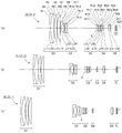
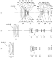
- (A) is a lens block diagram in the wide-angle end state of the zoom lens according to Example 1
- (b) is a lens block diagram in the intermediate focal length state
- (c) is a lens block diagram in the telephoto end state. is there.
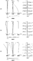
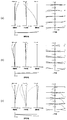
- (A) is various aberration diagrams at the time of focusing on infinity in the wide-angle end state of the zoom lens according to Example 1
- (b) is various aberration diagrams at the time of focusing on infinity in the intermediate focal length state
- (C) is an aberration diagram for focusing on infinity in the telephoto end state.
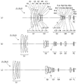
- (A) is a lens configuration diagram in the wide-angle end state of the zoom lens according to Example 2
- (b) is a lens configuration diagram in the intermediate focal length state
- (c) is a lens configuration diagram in the telephoto end state. is there.
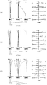
- (A) is various aberration diagrams at the time of focusing at infinity in the wide-angle end state of the zoom lens according to Example 2
- (b) is various aberration diagrams at the time of focusing at infinity in the intermediate focal length state
- (C) is an aberration diagram for focusing on infinity in the telephoto end state.
- (A) is a lens block diagram in the wide-angle end state of the zoom lens according to Example 3
- (b) is a lens block diagram in the intermediate focal length state
- (c) is a lens block diagram in the telephoto end state. is there.
- (A) is various aberration diagrams at the time of focusing on infinity in the wide-angle end state of the zoom lens according to Example 3
- (b) is various aberration diagrams at the time of focusing on infinity in the intermediate focal length state
- (C) is an aberration diagram for focusing on infinity in the telephoto end state.
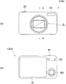
- (A) is a front view of a digital still camera
- (b) is a rear view of a digital still camera.
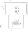
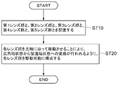
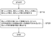
- FIG. 8 is a cross-sectional view taken along arrow AA ′ in FIG. 3 is a flowchart illustrating a method for manufacturing the zoom lens according to the first embodiment. It is a flowchart which shows the manufacturing method of the zoom lens which concerns on 2nd Embodiment. 9 is a flowchart illustrating a method for manufacturing a zoom lens according to a third embodiment.
- FIGS. 7A is a front view of the digital still camera CAM
- FIG. 7B is a rear view of the digital still camera CAM
- FIG. 8 is a cross-sectional view taken along arrow AA ′ in FIG.
- the photographing lens is composed of a zoom lens ZL according to a first embodiment described later.
- the auxiliary light emitting unit DL that emits auxiliary light when the subject is dark and the photographing lens (zoom lens ZL) are zoomed from the wide-angle end state (W) to the telephoto end state (T).
- the wide (W) -tele (T) button B2 and the function button B3 used for setting various conditions of the digital still camera CAM are arranged.
- the zoom lens ZL according to the first embodiment includes, for example, as shown in FIG. 1, a first lens group G1 having a positive refractive power arranged in order from the object side along the optical axis, and a negative refractive power. And a second lens group G2 having a positive refractive power, a fourth lens group G4 having a negative refractive power, and a fifth lens group G5 having a positive refractive power. Is done.
- the zoom lens ZL satisfies the condition expressed by the following conditional expression (1).
- f1 Focal length of the first lens group G1 ft: focal length of the zoom lens ZL in the telephoto end state.
- Conditional expression (1) is a conditional expression that defines the focal length of the first lens group G1 with respect to the focal length in the telephoto end state of the entire zoom lens ZL system.
- conditional expression (1) the telephoto ratio in the telephoto end state can be reduced, and the total length of the zoom lens ZL can be shortened. As a result, it is possible to realize a zoom lens ZL that is small but has a large zoom ratio and good optical performance. If the condition exceeds the upper limit value of the conditional expression (1), the zoom lens ZL is increased in size.
- the zoom lens ZL is miniaturized under a condition that exceeds the upper limit value of the conditional expression (1), the refractive power of the first lens group G1 decreases, so that the refractive power of the third lens group G3 needs to be increased. Since spherical aberration is greatly generated on the negative side in the entire zoom range, it is not preferable.
- the condition is lower than the lower limit value of the conditional expression (1), the refractive power of the first lens group G1 is increased, and spherical aberration and curvature of field are greatly generated on the minus side in the telephoto end state.
- fw focal length in the wide-angle end state of the zoom lens ZL
- f2 focal length of the second lens group G2.
- Conditional expression (2) is a conditional expression that defines the focal length of the first lens group G1 with respect to the focal length of the second lens group G2. By satisfying conditional expression (2), a small zoom lens ZL having high imaging performance can be achieved. It should be noted that if the condition exceeds the upper limit value of conditional expression (2), spherical aberration is greatly generated on the minus side in the telephoto end state, which is not preferable. On the other hand, when the condition is lower than the lower limit value of the conditional expression (2), spherical aberration is greatly generated on the plus side in the telephoto end state, which is not preferable.
- conditional expression (2) In order to ensure the effect of the first embodiment, it is desirable to set the upper limit value of conditional expression (2) to ⁇ 0.167. On the other hand, in order to ensure the effect of the first embodiment, it is desirable to set the lower limit value of the conditional expression (2) to ⁇ 0.176.
- the first lens group G1 preferably has three positive lenses. With this configuration, spherical aberration and coma can be favorably corrected in the telephoto end state.
- the first lens group G1 has a cemented lens of a positive lens and a negative lens, and is expressed by the following conditional expressions (3) and (4): Is preferably satisfied.
- nN1 refractive index with respect to d-line of the negative lens constituting the cemented lens of the first lens group G1
- nP1 refractive index with respect to d-line of the positive lens constituting the cemented lens of the first lens group G1
- ⁇ P1 Abbe number of the positive lens constituting the cemented lens of the first lens group G1.
- Conditional expression (3) is a conditional expression that defines the difference in refractive index between the positive lens and the negative lens that constitute the cemented lens of the first lens group G1. By satisfying conditional expression (3), it is possible to satisfactorily correct the spherical aberration generated in the first lens group G1. When the condition is less than the lower limit value of the conditional expression (3), the refractive index difference between the positive lens and the negative lens constituting the cemented lens of the first lens group G1 becomes too small, and the spherical aberration is bent in the telephoto end state. Since it becomes large, it is not preferable.
- Conditional expression (4) is a conditional expression that defines the Abbe number of the positive lens constituting the cemented lens of the first lens group G1. By satisfying conditional expression (4), it is possible to satisfactorily correct axial chromatic aberration and lateral chromatic aberration in the telephoto end state. In the case where the condition is less than the lower limit value of the conditional expression (4), the longitudinal chromatic aberration is greatly generated on the minus side and the lateral chromatic aberration is largely generated on the plus side in the telephoto end state, which is not preferable.
- conditional expression (4) it is desirable to set the lower limit value of conditional expression (4) to 90. Since a positive lens that satisfies the conditional expression (4) is soft and easily damaged, it is preferable that a negative lens is disposed on the object side of the positive lens and cemented. With this configuration, since the lens surface on the object side of the positive lens is covered with the negative lens, the lens surface on the object side of the positive lens that satisfies the conditional expression (4) is hardly damaged.
- condition expressed by the following conditional expression (5) is satisfied.
- Conditional expression (5) is a conditional expression that defines the focal length of the fourth lens group G4 with respect to the focal length in the telephoto end state of the entire zoom lens ZL system.
- the conditional expression (5) is satisfied, the front lens diameter of the zoom lens ZL can be reduced.
- the condition exceeds the upper limit value of the conditional expression (5), spherical aberration is greatly generated on the plus side in the wide-angle end state, which is not preferable.
- the condition is lower than the lower limit value of the conditional expression (5), the effect of the negative lens on the image side from the aperture stop S becomes small, and it becomes difficult to sufficiently reduce the front lens diameter of the zoom lens ZL.
- conditional expression (5) In order to ensure the effect of the first embodiment, it is desirable to set the upper limit value of conditional expression (5) to ⁇ 0.15. On the other hand, in order to make the effect of the first embodiment more certain, it is desirable to set the lower limit value of the conditional expression (5) to ⁇ 0.17.
- the fourth lens group G4 includes a cemented lens of one positive lens and one negative lens.
- the fourth lens group G4 includes a cemented lens of one positive lens and one negative lens.
- an aperture stop S is disposed in the vicinity of the object side of the third lens group G3 to satisfy the condition represented by the following conditional expression (6).
- ⁇ Zwt the moving distance on the optical axis of the aperture stop S toward the object side during zooming from the wide-angle end state to the telephoto end state.
- Conditional expression (6) is the movement of the aperture stop S on the optical axis toward the object side during zooming from the wide-angle end state to the telephoto end state with respect to the focal length in the telephoto end state of the entire zoom lens ZL system. It is a conditional expression that defines the distance. In general, as the moving distance of the aperture stop S on the optical axis increases, the amount of change in the F number due to zooming increases. Therefore, by satisfying conditional expression (6), the focal length of the entire system in the telephoto end state is set while setting the change amount of the F-number due to zooming from the wide-angle end state to the telephoto end state within an appropriate range. Larger zoom ratios can be secured.
- condition exceeds the upper limit value of conditional expression (6), the F-number in the telephoto end state becomes larger than necessary, or the F-number in the wide-angle end state becomes small, making it difficult to correct spherical aberration. Therefore, it is not preferable.
- condition is less than the lower limit value of conditional expression (6), it is not preferable to reduce the F-number in the wide-angle end state because the F-number in the telephoto end state also decreases and it becomes difficult to correct spherical aberration. .
- conditional expression (6) In order to ensure the effect of the first embodiment, it is desirable to set the upper limit value of conditional expression (6) to 0.088. On the other hand, in order to ensure the effect of the first embodiment, it is desirable to set the lower limit value of conditional expression (6) to 0.086.
- a manufacturing method of the zoom lens ZL according to the first embodiment will be described with reference to FIG.
- a group G3, a fourth lens group G4 having a negative refractive power, and a fifth lens group G5 having a positive refractive power are incorporated (step ST10).
- the first lens group G1, the second lens group G2, the third lens group G3, the fourth lens group G4, and the fifth lens group G5 along the optical axis the telephoto end state is changed from the wide-angle end state.
- the first lens group G1, the second lens group G2, the third lens group G3, the fourth lens group G4, and the fifth lens group G5 are configured to be drivable so that zooming is performed. Step ST20).
- step ST10 in which the lens is assembled the first lens group G1, the second lens group G2, the third lens group G3, the fourth lens group G4, and the fifth lens group G1, the second lens group G2, and the fifth lens group G1, so as to satisfy the above-described conditional expression (1).
- the lens group G5 is disposed. According to such a manufacturing method, it is possible to obtain a zoom lens ZL having a large zoom ratio and good optical performance while being small.
- the zoom lens ZL according to the second embodiment includes, for example, as shown in FIG. 1, a first lens group G1 having a positive refractive power arranged in order from the object side along the optical axis, and a negative refractive power. And a second lens group G2 having a positive refractive power, a fourth lens group G4 having a negative refractive power, and a fifth lens group G5 having a positive refractive power. Is done.
- G3, the fourth lens group G4, and the fifth lens group G5 each move along the optical axis.
- the second lens group G2 includes a first negative lens, a second negative lens, a positive lens, and a third negative lens, which are arranged in order from the object side along the optical axis.
- the negative lens is cemented.
- fw focal length in the wide-angle end state of the zoom lens ZL
- ft focal length of the zoom lens ZL in the telephoto end state
- f1 Focal length of the first lens group G1
- f2 focal length of the second lens group G2.
- Conditional expression (7) is a conditional expression that defines the focal length of the first lens group G1 with respect to the focal length of the second lens group G2. By satisfying conditional expression (7), a small zoom lens ZL having high imaging performance can be achieved. Note that if the condition exceeds the upper limit value of the conditional expression (7), spherical aberration is greatly generated on the minus side in the telephoto end state, which is not preferable. On the other hand, when the condition is lower than the lower limit value of the conditional expression (7), spherical aberration is greatly generated on the plus side in the telephoto end state, which is not preferable.
- conditional expression (7) In order to ensure the effect of the second embodiment, it is desirable to set the upper limit value of conditional expression (7) to ⁇ 0.167. On the other hand, in order to ensure the effect of the second embodiment, it is desirable to set the lower limit value of the conditional expression (7) to ⁇ 0.176.
- ft focal length of the zoom lens ZL in the telephoto end state
- f4 focal length of the fourth lens group G4.
- Conditional expression (8) is a conditional expression that defines the focal length of the fourth lens group G4 with respect to the focal length in the telephoto end state of the entire zoom lens ZL system.
- the conditional expression (8) is satisfied, the front lens diameter of the zoom lens ZL can be reduced. It should be noted that if the condition exceeds the upper limit value of conditional expression (8), spherical aberration is greatly generated on the plus side in the wide-angle end state, which is not preferable.
- the condition is lower than the lower limit value of the conditional expression (8), the effect of the negative lens on the image side from the aperture stop S becomes small, and it becomes difficult to sufficiently reduce the front lens diameter of the zoom lens ZL.
- conditional expression (8) In order to ensure the effect of the second embodiment, it is desirable to set the upper limit value of conditional expression (8) to ⁇ 0.150. On the other hand, in order to ensure the effect of the second embodiment, it is desirable to set the lower limit value of the conditional expression (8) to ⁇ 0.170.
- the fourth lens group G4 includes a cemented lens of one positive lens and one negative lens.
- the fourth lens group G4 includes a cemented lens of one positive lens and one negative lens.
- a manufacturing method of the zoom lens ZL according to the second embodiment will be described with reference to FIG.
- a group G3, a fourth lens group G4 having a negative refractive power, and a fifth lens group G5 having a positive refractive power are incorporated (step ST10).
- the first lens group G1, the second lens group G2, the third lens group G3, the fourth lens group G4, and the fifth lens group G5 along the optical axis the telephoto end state is changed from the wide-angle end state.
- the first lens group G1, the second lens group G2, the third lens group G3, the fourth lens group G4, and the fifth lens group G5 are configured to be drivable so that zooming is performed.
- step ST10 in which the lens is incorporated, a first negative lens, a second negative lens, a positive lens, and a third negative lens are arranged in order from the object side along the optical axis as the second lens group G2.
- the positive lens and the third negative lens are cemented. According to such a manufacturing method, it is possible to obtain a zoom lens ZL having a large zoom ratio and good optical performance while being small.
- the zoom lens ZL according to the third embodiment includes, for example, as shown in FIG. 1, a first lens group G1 having a positive refractive power arranged in order from the object side along the optical axis, and a negative refractive power. And a second lens group G2 having a positive refractive power, a fourth lens group G4 having a negative refractive power, and a fifth lens group G5 having a positive refractive power. Is done.
- the zoom lens ZL satisfies the conditions expressed by the following conditional expressions (9) to (10).
- f2 focal length of the second lens group G2
- TL2 the length of the second lens group G2 on the optical axis
- f4 focal length of the fourth lens group G4
- ft focal length of the zoom lens ZL in the telephoto end state.
- conditional expressions (9) to (10) it is possible to realize a zoom lens ZL having a large zoom ratio and good optical performance while being small.
- Conditional expression (9) is a conditional expression that defines the focal length of the second lens group G2 with respect to the length of the second lens group G2 on the optical axis.
- conditional expression (9) the length of the second lens group G2 on the optical axis is shortened, so that the overall length of the zoom lens ZL is not increased, and the second lens group G2 is zoomed. The amount of movement can be secured.
- condition is less than the lower limit value of the conditional expression (9)
- the length of the second lens group G2 on the optical axis is increased, the optical total length is increased, or the principal point distance of the second lens group G2 is increased. This is not preferable because the spherical aberration becomes large on the plus side in the telephoto end state.
- the focal length of the second lens group G2 becomes long, and the movement amount of the second lens group G2 becomes large in order to secure a zoom ratio.
- This increases the size of the zoom lens ZL. If the zoom lens ZL is downsized under the condition that exceeds the upper limit value of the conditional expression (9), the refractive power of the third lens group G3 and the fourth lens group G4 is increased, and the third lens group G3 and the fourth lens are increased. It is not preferable because the telephoto ratio in the group G4 needs to be reduced, and spherical aberration is greatly generated on the negative side in the entire zooming range.
- conditional expression (9) In order to ensure the effect of the third embodiment, it is desirable to set the upper limit value of conditional expression (9) to ⁇ 0.69. It is more desirable to set the upper limit value of conditional expression (9) to -0.72. On the other hand, in order to ensure the effect of the third embodiment, it is desirable to set the lower limit value of the conditional expression (9) to ⁇ 0.81. It is more desirable to set the lower limit value of conditional expression (9) to ⁇ 0.77.
- Conditional expression (10) is a conditional expression that defines the focal length of the fourth lens group G4 with respect to the focal length in the telephoto end state of the entire zoom lens ZL system.
- conditional expression (10) is satisfied, the front lens diameter of the zoom lens ZL can be reduced. If the condition exceeds the upper limit value of conditional expression (10), spherical aberration is greatly generated on the plus side in the wide-angle end state, which is not preferable.
- the condition is lower than the lower limit value of the conditional expression (10)
- the effect of the negative lens on the image side from the aperture stop S becomes small, and it becomes difficult to sufficiently reduce the front lens diameter of the zoom lens ZL.
- conditional expression (10) In order to ensure the effect of the third embodiment, it is desirable to set the upper limit of conditional expression (10) to ⁇ 0.150. On the other hand, in order to make the effect of the third embodiment more reliable, it is desirable to set the lower limit value of the conditional expression (10) to ⁇ 0.170.
- f1 Focal length of the first lens group G1 fw: focal length in the wide-angle end state of the zoom lens ZL.
- Conditional expression (11) is a conditional expression that defines the focal length of the first lens group G1 with respect to the focal length of the second lens group G2.
- conditional expression (3) By satisfying conditional expression (3), a small zoom lens ZL having high imaging performance can be achieved. If the condition exceeds the upper limit value of the conditional expression (11), spherical aberration is greatly generated on the minus side in the telephoto end state, which is not preferable. On the other hand, when the condition is lower than the lower limit value of the conditional expression (11), spherical aberration is greatly generated on the plus side in the telephoto end state, which is not preferable.
- conditional expression (11) In order to ensure the effect of the third embodiment, it is desirable to set the upper limit value of conditional expression (11) to ⁇ 0.167. On the other hand, in order to ensure the effect of the third embodiment, it is desirable to set the lower limit value of the conditional expression (11) to ⁇ 0.176.
- the fourth lens group G4 includes a cemented lens of one positive lens and one negative lens.
- the fourth lens group G4 includes a cemented lens of one positive lens and one negative lens.
- n2f refractive index with respect to d-line of the most image side lens in the second lens group G2
- ft focal length of the zoom lens ZL in the telephoto end state
- ⁇ 2f Abbe number of the most image-side lens in the second lens group G2
- r2f radius of curvature of the lens surface closest to the image side in the second lens group G2.
- Conditional expression (12) is a conditional expression that defines the refractive index with respect to the d-line of the most image side lens in the second lens group G2 and the radius of curvature of the most image side lens surface in the second lens group G2.
- a manufacturing method of the zoom lens ZL according to the third embodiment will be described with reference to FIG.
- a group G3, a fourth lens group G4 having a negative refractive power, and a fifth lens group G5 having a positive refractive power are incorporated (step ST10).
- the first lens group G1, the second lens group G2, the third lens group G3, the fourth lens group G4, and the fifth lens group G5 along the optical axis the telephoto end state is changed from the wide-angle end state.
- the first lens group G1, the second lens group G2, the third lens group G3, the fourth lens group G4, and the fifth lens group G5 are configured to be drivable so that zooming is performed. Step ST20).
- step ST10 in which the lens is incorporated the first lens group G1, the second lens group G2, the third lens group G3, and the fourth lens group G4 are set so as to satisfy the conditional expressions (9) to (10) described above. , And the fifth lens group G5. According to such a manufacturing method, it is possible to obtain a zoom lens ZL having a large zoom ratio and good optical performance while being small.
- FIGS. 1A is a lens configuration diagram in the wide-angle end state of the zoom lens ZL (ZL1) according to the first embodiment
- FIG. 1B is a lens configuration diagram in an intermediate focal length state
- FIG. ) Is a lens configuration diagram in the telephoto end state.
- the zoom lens ZL1 according to the first example includes a first lens group G1 having a positive refractive power, a second lens group G2 having a negative refractive power, arranged in order from the object side along the optical axis, and a positive lens.
- a third lens group G3 having a negative refractive power, a fourth lens group G4 having a negative refractive power, and a fifth lens group G5 having a positive refractive power During zooming from the wide-angle end state to the telephoto end state, the distance between the first lens group G1 and the second lens group G2 increases, and the second lens group G2 and the third lens group G3 The first lens group G1, the second lens group G1, the fourth lens group G4, the distance between the third lens group G3 and the fourth lens group G4 changes, and the distance between the fourth lens group G4 and the fifth lens group G5 changes.
- the second lens group G2, the third lens group G3, the fourth lens group G4, and the fifth lens group G5 each move along the optical axis.
- the first lens group G1 is arranged in order from the object side along the optical axis, the meniscus negative lens L11 having a convex surface facing the object side, the first positive lens L12 having a biconvex shape, and the convex surface facing the object side.
- the negative lens L11 and the first positive lens L12 are cemented lenses that are cemented with each other.
- the second lens group G2 is arranged in order from the object side along the optical axis, and includes a first negative lens L21 having a concave surface on the image plane I side, a biconcave second negative lens L22, and a biconvex shape. It is composed of a positive lens L23 having a shape and a third negative lens L24 having a biconcave shape.
- the positive lens L23 and the third negative lens L24 are cemented lenses that are cemented with each other.
- the third lens group G3 includes a biconvex first positive lens L31, a biconvex second positive lens L32, and a biconcave negative lens L33 arranged in order from the object side along the optical axis. And a biconvex third positive lens L34.
- the second positive lens L32 and the negative lens L33 are cemented lenses that are cemented with each other.
- the lens surfaces on both sides of the first positive lens L31 are aspherical.
- the fourth lens group G4 is composed of a biconvex positive lens L41 and a biconcave negative lens L42 arranged in order from the object side along the optical axis.
- the positive lens L41 and the negative lens L42 are cemented lenses that are cemented with each other.
- the fifth lens group G5 includes a biconvex positive lens L51 arranged in order from the object side along the optical axis, and a meniscus negative lens L52 having a convex surface directed toward the image plane I.
- the positive lens L51 and the negative lens L52 are cemented lenses that are cemented with each other.
- the object side lens surface of the positive lens L51 is aspheric.
- the aperture stop S is disposed near the object side of the third lens group G3, and moves in the same orbit as the third lens group G3 during zooming from the wide-angle end state to the telephoto end state. ing. Note that focusing from an infinitely distant object to a close object (finite distance object) is performed by moving the fifth lens group G5 to the object side along the optical axis.
- the filter group FL arranged between the fifth lens group G5 and the image plane I is composed of a low-pass filter, an infrared cut filter, and the like.
- Tables 1 to 3 are shown below. These are tables listing the values of the specifications of the zoom lenses according to the first to third examples.
- the values of the focal length f, F number FNO, half angle of view ⁇ , and image height Y of the zoom lens ZL in each of the wide-angle end state, the intermediate focal length state, and the telephoto end state are shown. Each is shown.
- the first column (surface number) is the lens surface number when counted from the object side
- the second column R is the radius of curvature of the lens surface
- the third column D is the lens surface number.
- subjected to the right of the 1st column shows that the lens surface is an aspherical surface.
- the aspheric coefficient shown in [Aspherical surface data] is the distance along the optical axis from the tangential plane of each vertex of the aspheric surface to each aspheric surface at height y (y is the height in the direction perpendicular to the optical axis).
- the sag amount is X (y)
- the paraxial radius of curvature (the radius of curvature of the reference sphere) is R
- the conic constant ⁇
- the secondary aspherical coefficient A2 is 0, and the description is omitted.
- “En” indicates “ ⁇ 10 ⁇ n ”.
- the [variable interval data] includes the focal length f of the zoom lens ZL, the variable interval, the back focus BF, and the total length TL (zoom) in each of the wide-angle end state, intermediate focal length state, and telephoto end state (when focusing on infinity).
- the values of the length from the first optical surface of the lens ZL to the final optical surface (image surface I) are shown.
- the value of the focal length of each lens group is shown.
- [Conditional Expression Corresponding Value] indicates the corresponding value of each conditional expression.
- the focal length f, the radius of curvature R, and other length units listed in all the following specifications are generally “mm”, but the optical system may be proportionally enlarged or reduced. Since equivalent optical performance can be obtained, the present invention is not limited to this.
- the same reference numerals as those in the present embodiment are used for specification values in second to third embodiments described later.
- Table 1 below shows each item in the first embodiment.
- the curvature radii R of the first surface to the 28th surface in Table 1 correspond to the symbols R1 to R28 attached to the first surface to the 28th surface in FIG.
- the 29th to 32nd surfaces are flat surfaces, and the corresponding surfaces are not shown in FIG.
- the group numbers G1 to G5 in Table 1 correspond to the lens groups G1 to G5 in FIG.
- the lens surfaces of the sixteenth surface, the seventeenth surface, and the twenty-sixth surface are aspherical.
- FIGS. 2A to 2C are graphs showing various aberrations of the zoom lens ZL1 according to the first example.
- FNO represents an F number
- Y represents an image height.
- the solid line shows the sagittal image plane
- the broken line shows the meridional image plane. The description of the aberration diagrams is the same in the other examples.
- FIG. 3A is a lens configuration diagram in the wide-angle end state of the zoom lens ZL (ZL2) according to the second example
- FIG. 3B is a lens configuration diagram in the intermediate focal length state
- FIG. ) Is a lens configuration diagram in the telephoto end state.
- the zoom lens ZL2 according to the second example includes a first lens group G1 having a positive refractive power, a second lens group G2 having a negative refractive power, arranged in order from the object side along the optical axis, And a third lens group G3 having a negative refractive power, a fourth lens group G4 having a negative refractive power, and a fifth lens group G5 having a positive refractive power.
- the distance between the first lens group G1 and the second lens group G2 increases, and the second lens group G2 and the third lens group G3
- the first lens group G1, the second lens group G1, the fourth lens group G4, the distance between the third lens group G3 and the fourth lens group G4 changes, and the distance between the fourth lens group G4 and the fifth lens group G5 changes.
- the second lens group G2, the third lens group G3, the fourth lens group G4, and the fifth lens group G5 each move along the optical axis.
- the first lens group G1 is arranged in order from the object side along the optical axis, the meniscus negative lens L11 having a convex surface facing the object side, the first positive lens L12 having a biconvex shape, and the convex surface facing the object side.
- the negative lens L11 and the first positive lens L12 are cemented lenses that are cemented with each other.
- the second lens group G2 is arranged in order from the object side along the optical axis, and includes a first negative lens L21 having a concave surface on the image plane I side, a biconcave second negative lens L22, and a biconvex shape. It is composed of a positive lens L23 having a shape and a third negative lens L24 having a biconcave shape.
- the positive lens L23 and the third negative lens L24 are cemented lenses that are cemented with each other.
- the third lens group G3 includes a biconvex first positive lens L31 arranged in order from the object side along the optical axis, a second positive lens L32 having a convex surface directed toward the object side, and an image plane I side. And a negative lens L33 having a concave surface directed to the second positive lens L34 and a biconvex third positive lens L34.
- the second positive lens L32 and the negative lens L33 are cemented lenses that are cemented with each other.
- the lens surfaces on both sides of the first positive lens L31 are aspherical.
- the fourth lens group G4 is composed of a biconvex positive lens L41 and a biconcave negative lens L42 arranged in order from the object side along the optical axis.
- the positive lens L41 and the negative lens L42 are cemented lenses that are cemented with each other.
- the fifth lens group G5 includes a biconvex positive lens L51 arranged in order from the object side along the optical axis, and a meniscus negative lens L52 having a convex surface directed toward the image plane I.
- the positive lens L51 and the negative lens L52 are cemented lenses that are cemented with each other.
- the object side lens surface of the positive lens L51 is aspheric.
- the aperture stop S is disposed near the object side of the third lens group G3, and moves in the same orbit as the third lens group G3 during zooming from the wide-angle end state to the telephoto end state. ing. Note that focusing from an infinitely distant object to a close object (finite distance object) is performed by moving the fifth lens group G5 to the object side along the optical axis.
- the filter group FL arranged between the fifth lens group G5 and the image plane I is composed of a low-pass filter, an infrared cut filter, and the like.
- Table 2 below shows each item in the second embodiment.
- the curvature radii R of the first surface to the 28th surface in Table 2 correspond to the symbols R1 to R28 attached to the first surface to the 28th surface in FIG.
- the 29th to 32nd surfaces are flat surfaces, and the corresponding surfaces are not shown in FIG.
- the group numbers G1 to G5 in Table 2 correspond to the lens groups G1 to G5 in FIG.
- the lens surfaces of the sixteenth surface, the seventeenth surface, and the twenty-sixth surface are formed in an aspherical shape.
- FIG. 4A to 4C are graphs showing various aberrations of the zoom lens ZL2 according to the second example.
- FIG. 5A is a lens configuration diagram in the wide-angle end state of the zoom lens ZL (ZL3) according to the third example
- FIG. 5B is a lens configuration diagram in the intermediate focal length state
- FIG. ) Is a lens configuration diagram in the telephoto end state.
- the zoom lens ZL3 according to the third example includes a first lens group G1 having a positive refractive power, a second lens group G2 having a negative refractive power, arranged in order from the object side along the optical axis, and a positive lens And a third lens group G3 having a negative refractive power, a fourth lens group G4 having a negative refractive power, and a fifth lens group G5 having a positive refractive power.
- the distance between the first lens group G1 and the second lens group G2 increases, and the second lens group G2 and the third lens group G3
- the first lens group G1, the second lens group G1, the fourth lens group G4, the distance between the third lens group G3 and the fourth lens group G4 changes, and the distance between the fourth lens group G4 and the fifth lens group G5 changes.
- the second lens group G2, the third lens group G3, the fourth lens group G4, and the fifth lens group G5 each move along the optical axis.
- the first lens group G1 is arranged in order from the object side along the optical axis, the meniscus negative lens L11 having a convex surface facing the object side, the first positive lens L12 having a biconvex shape, and the convex surface facing the object side.
- the negative lens L11 and the first positive lens L12 are cemented lenses that are cemented with each other.
- the second lens group G2 is arranged in order from the object side along the optical axis, the first negative lens L21 having a concave surface on the image surface I side, and a second meniscus shape having a convex surface on the image surface I side.
- the positive lens L23 and the third negative lens L24 are cemented lenses that are cemented with each other.
- the third lens group G3 includes a biconvex first positive lens L31, a biconvex second positive lens L32, and a biconcave negative lens L33 arranged in order from the object side along the optical axis. And a biconvex third positive lens L34.
- the second positive lens L32 and the negative lens L33 are cemented lenses that are cemented with each other.
- the lens surfaces on both sides of the first positive lens L31 are aspherical.
- the fourth lens group G4 is composed of a meniscus positive lens L41 having a convex surface facing the object side and a meniscus negative lens L42 having a convex surface facing the object side, which are arranged in order from the object side along the optical axis. Is done.
- the positive lens L41 and the negative lens L42 are cemented lenses that are cemented with each other.
- the fifth lens group G5 includes a biconvex positive lens L51 arranged in order from the object side along the optical axis, and a meniscus negative lens L52 having a convex surface directed toward the image plane I.
- the positive lens L51 and the negative lens L52 are cemented lenses that are cemented with each other.
- the object side lens surface of the positive lens L51 is aspheric.
- the aperture stop S is disposed near the object side of the third lens group G3, and moves in the same orbit as the third lens group G3 during zooming from the wide-angle end state to the telephoto end state. ing. Note that focusing from an infinitely distant object to a close object (finite distance object) is performed by moving the fifth lens group G5 to the object side along the optical axis.
- the filter group FL arranged between the fifth lens group G5 and the image plane I is composed of a low-pass filter, an infrared cut filter, and the like.
- Table 3 below shows each item in the third example.
- the curvature radii R of the first surface to the 28th surface in Table 3 correspond to the reference signs R1 to R28 attached to the first surface to the 28th surface in FIG.
- the 29th to 32nd surfaces are flat surfaces, and the corresponding surfaces are not shown in FIG.
- Group numbers G1 to G5 in Table 3 correspond to the lens groups G1 to G5 in FIG.
- the lens surfaces of the sixteenth surface, the seventeenth surface, and the twenty-sixth surface are formed in an aspherical shape.
- FIGS. 6A to 6C are graphs showing various aberrations of the zoom lens ZL3 according to the third example.
- the five-group configuration is shown as a zoom lens. Further, a configuration in which a lens or a lens group is added to the most object side, or a configuration in which a lens or a lens group is added to the most image side may be used.
- the lens group refers to a portion having at least one lens separated by an air interval that changes during zooming.
- the lens group may be a focusing lens group that performs focusing from an object at infinity to a near object by moving a single lens group, a plurality of lens groups, or a partial lens group in the optical axis direction.
- This focusing lens group can be applied to autofocus, and is also suitable for driving a motor for autofocus (using an ultrasonic motor or the like).
- the fifth lens group is preferably a focusing lens group.
- the lens group or the partial lens group is moved so as to have a component in a direction perpendicular to the optical axis, or is rotated (swayed) in the in-plane direction including the optical axis to reduce image blur caused by camera shake.
- a vibration-proof lens group to be corrected may be used.
- the third lens group is preferably an anti-vibration lens group.
- the lens surface may be formed of a spherical surface, a flat surface, or an aspheric surface.
- the lens surface is a spherical surface or a flat surface, lens processing and assembly adjustment are facilitated, and optical performance deterioration due to processing and assembly adjustment errors can be prevented. Further, even when the image plane is deviated, it is preferable because there is little deterioration in drawing performance.
- the aspheric surface is an aspheric surface by grinding, a glass mold aspheric surface made of glass with an aspheric shape, or a composite aspheric surface made of resin with an aspheric shape on the glass surface. Any aspherical surface may be used.
- the lens surface may be a diffractive surface, and the lens may be a gradient index lens (GRIN lens) or a plastic lens.
- GRIN lens gradient index lens
- the aperture stop is preferably arranged in the third lens group, but the role of the aperture stop may be substituted by a lens frame without providing a member as an aperture stop.
- the aperture stop moves in the same orbit as the third lens group during zooming from the wide-angle end state to the telephoto end state. You may make it move on a separate track from the group.
- each lens surface may be provided with an antireflection film having a high transmittance in a wide wavelength region in order to reduce flare and ghost and achieve high optical performance with high contrast.
- the zoom lens of the present embodiment has a zoom ratio of about 50 to 70.
- the zoom lens according to the present embodiment is used in a digital still camera
- the present invention is not limited to this, and can also be used in an optical device such as a digital video camera.
- CAM digital still camera (optical equipment) ZL zoom lens G1 first lens group G2 second lens group G3 third lens group G4 fourth lens group G5 fifth lens group S aperture stop I image plane
Landscapes
- Physics & Mathematics (AREA)
- General Physics & Mathematics (AREA)
- Optics & Photonics (AREA)
- Lenses (AREA)
- Nonlinear Science (AREA)
Abstract
正の屈折力を有する第1レンズ群(G1)と、負の屈折力を有する第2レンズ群(G2)と、正の屈折力を有する第3レンズ群(G3)と、負の屈折力を有する第4レンズ群(G4)と、正の屈折力を有する第5レンズ群(G5)とを備えたズームレンズ(ZL)において、広角端状態から望遠端状態への変倍の際、第1レンズ群(G1)と第2レンズ群(G2)との間隔、第2レンズ群(G2)と第3レンズ群(G3)との間隔、第3レンズ群(G3)と第4レンズ群(G4)との間隔、および第4レンズ群(G4)と第5レンズ群(G5)との間隔がそれぞれ変化するように、第1~第5レンズ群(G1~G5)がそれぞれ光軸に沿って移動し、条件式「0.25<f1/ft<0.38」を満足するようになっている。
Description
本発明は、ズームレンズ、光学機器、およびズームレンズの製造方法に関する。
従来から、写真用カメラ、電子スチルカメラ、ビデオカメラ等に適用可能であって、大きな変倍比を有したズームレンズが種々提案されている(例えば、特許文献1を参照)。
しかしながら、従来のズームレンズでは、光学系全体の小型化を図りながら、変倍比を大きくすることが困難であった。
本発明は、このような問題に鑑みてなされたものであり、小型でありながら大きな変倍比を有し、良好な光学性能を備えたズームレンズ、光学機器、およびズームレンズの製造方法を提供することを目的とする。
第1の本発明に係るズームレンズは、光軸に沿って物体側から順に並んだ、正の屈折力を有する第1レンズ群と、負の屈折力を有する第2レンズ群と、正の屈折力を有する第3レンズ群と、負の屈折力を有する第4レンズ群と、正の屈折力を有する第5レンズ群とを備え、広角端状態から望遠端状態への変倍の際、前記第1レンズ群と前記第2レンズ群との間隔、前記第2レンズ群と前記第3レンズ群との間隔、前記第3レンズ群と前記第4レンズ群との間隔、および前記第4レンズ群と前記第5レンズ群との間隔がそれぞれ変化するように、前記第1レンズ群、前記第2レンズ群、前記第3レンズ群、前記第4レンズ群、および前記第5レンズ群がそれぞれ光軸に沿って移動し、以下の条件式を満足している。
0.25<f1/ft<0.38
但し、
f1:前記第1レンズ群の焦点距離、
ft:前記ズームレンズの望遠端状態における焦点距離。
但し、
f1:前記第1レンズ群の焦点距離、
ft:前記ズームレンズの望遠端状態における焦点距離。
第1の本発明に係るズームレンズにおいて、以下の条件式を満足することが好ましい。
-0.180<(f1×fw)/(f2×ft)<-0.160
但し、
fw:前記ズームレンズの広角端状態における焦点距離、
f2:前記第2レンズ群の焦点距離。
但し、
fw:前記ズームレンズの広角端状態における焦点距離、
f2:前記第2レンズ群の焦点距離。
第1の本発明に係るズームレンズにおいて、前記第1レンズ群は、3枚の正レンズを有することが好ましい。
第1の本発明に係るズームレンズにおいて、前記第1レンズ群は、正レンズと負レンズとの接合レンズを有し、以下の条件式を満足することが好ましい。
0.367<nN1-nP1
80<νP1
但し、
nN1:前記第1レンズ群の前記接合レンズを構成する前記負レンズのd線に対する屈折率、
nP1:前記第1レンズ群の前記接合レンズを構成する前記正レンズのd線に対する屈折率、
νP1:前記第1レンズ群の前記接合レンズを構成する前記正レンズのアッベ数。
80<νP1
但し、
nN1:前記第1レンズ群の前記接合レンズを構成する前記負レンズのd線に対する屈折率、
nP1:前記第1レンズ群の前記接合レンズを構成する前記正レンズのd線に対する屈折率、
νP1:前記第1レンズ群の前記接合レンズを構成する前記正レンズのアッベ数。
第1の本発明に係るズームレンズにおいて、以下の条件式を満足することが好ましい。
-0.18<f4/ft<-0.14
但し、
f4:前記第4レンズ群の焦点距離。
但し、
f4:前記第4レンズ群の焦点距離。
第1の本発明に係るズームレンズにおいて、前記第4レンズ群は、1枚の正レンズと1枚の負レンズとの接合レンズからなることが好ましい。
第1の本発明に係るズームレンズにおいて、前記第3レンズ群の物体側近傍に開口絞りが配設され、以下の条件式を満足することが好ましい。
0.084<ΔZwt/ft<0.090
但し、
ΔZwt:広角端状態から望遠端状態への変倍の際における、前記開口絞りの物体側への光軸上の移動距離。
但し、
ΔZwt:広角端状態から望遠端状態への変倍の際における、前記開口絞りの物体側への光軸上の移動距離。
第2の本発明に係るズームレンズは、光軸に沿って物体側から順に並んだ、正の屈折力を有する第1レンズ群と、負の屈折力を有する第2レンズ群と、正の屈折力を有する第3レンズ群と、負の屈折力を有する第4レンズ群と、正の屈折力を有する第5レンズ群とを備え、広角端状態から望遠端状態への変倍の際、前記第1レンズ群と前記第2レンズ群との間隔、前記第2レンズ群と前記第3レンズ群との間隔、前記第3レンズ群と前記第4レンズ群との間隔、および前記第4レンズ群と前記第5レンズ群との間隔がそれぞれ変化するように、前記第1レンズ群、前記第2レンズ群、前記第3レンズ群、前記第4レンズ群、および前記第5レンズ群がそれぞれ光軸に沿って移動し、前記第2レンズ群は、光軸に沿って物体側から順に並んだ、第1負レンズと、第2負レンズと、正レンズと、第3負レンズとからなり、前記正レンズと前記第3負レンズとが接合されるようになっている。
第2の本発明に係るズームレンズにおいて、以下の条件式を満足することが好ましい。
-0.180<(f1×fw)/(f2×ft)<-0.160
但し、
fw:前記ズームレンズの広角端状態における焦点距離、
ft:前記ズームレンズの望遠端状態における焦点距離、
f1:前記第1レンズ群の焦点距離、
f2:前記第2レンズ群の焦点距離。
但し、
fw:前記ズームレンズの広角端状態における焦点距離、
ft:前記ズームレンズの望遠端状態における焦点距離、
f1:前記第1レンズ群の焦点距離、
f2:前記第2レンズ群の焦点距離。
第2の本発明に係るズームレンズにおいて、以下の条件式を満足することが好ましい。
-0.180<f4/ft<-0.140
但し、
ft:前記ズームレンズの望遠端状態における焦点距離、
f4:前記第4レンズ群の焦点距離。
但し、
ft:前記ズームレンズの望遠端状態における焦点距離、
f4:前記第4レンズ群の焦点距離。
第2の本発明に係るズームレンズにおいて、前記第4レンズ群は、1枚の正レンズと1枚の負レンズとの接合レンズからなることが好ましい。
第3の本発明に係るズームレンズは、光軸に沿って物体側から順に並んだ、正の屈折力を有する第1レンズ群と、負の屈折力を有する第2レンズ群と、正の屈折力を有する第3レンズ群と、負の屈折力を有する第4レンズ群と、正の屈折力を有する第5レンズ群とを備え、広角端状態から望遠端状態への変倍の際、前記第1レンズ群と前記第2レンズ群との間隔、前記第2レンズ群と前記第3レンズ群との間隔、前記第3レンズ群と前記第4レンズ群との間隔、および前記第4レンズ群と前記第5レンズ群との間隔がそれぞれ変化するように、前記第1レンズ群、前記第2レンズ群、前記第3レンズ群、前記第4レンズ群、および前記第5レンズ群がそれぞれ光軸に沿って移動し、以下の条件式を満足している。
-0.90<f2/TL2<-0.60
-0.180<f4/ft<-0.140
但し、
f2:前記第2レンズ群の焦点距離、
TL2:前記第2レンズ群の光軸上の長さ、
f4:前記第4レンズ群の焦点距離、
ft:前記ズームレンズの望遠端状態における焦点距離。
-0.180<f4/ft<-0.140
但し、
f2:前記第2レンズ群の焦点距離、
TL2:前記第2レンズ群の光軸上の長さ、
f4:前記第4レンズ群の焦点距離、
ft:前記ズームレンズの望遠端状態における焦点距離。
第3の本発明に係るズームレンズにおいて、以下の条件式を満足することが好ましい。
-0.180<(f1×fw)/(f2×ft)<-0.160
但し、
f1:前記第1レンズ群の焦点距離、
fw:前記ズームレンズの広角端状態における焦点距離。
但し、
f1:前記第1レンズ群の焦点距離、
fw:前記ズームレンズの広角端状態における焦点距離。
第3の本発明に係るズームレンズにおいて、前記第4レンズ群は、1枚の正レンズと1枚の負レンズとの接合レンズからなることが好ましい。
第1の本発明に係る光学機器は、物体の像を所定の面上に結像させるズームレンズを備えた光学機器であって、前記ズームレンズとして第1の本発明に係るズームレンズを用いている。同様に、第2の本発明に係る光学機器は、物体の像を所定の面上に結像させるズームレンズを備えた光学機器であって、前記ズームレンズとして第2の本発明に係るズームレンズを用いて構成され、第3の本発明に係る光学機器は、物体の像を所定の面上に結像させるズームレンズを備えた光学機器であって、前記ズームレンズとして第3の本発明に係るズームレンズを用いて構成される。
第1の本発明に係るズームレンズの製造方法は、光軸に沿って物体側から順に、正の屈折力を有する第1レンズ群と、負の屈折力を有する第2レンズ群と、正の屈折力を有する第3レンズ群と、負の屈折力を有する第4レンズ群と、正の屈折力を有する第5レンズ群とを配置し、広角端状態から望遠端状態への変倍の際、前記第1レンズ群と前記第2レンズ群との間隔、前記第2レンズ群と前記第3レンズ群との間隔、前記第3レンズ群と前記第4レンズ群との間隔、および前記第4レンズ群と前記第5レンズ群との間隔がそれぞれ変化するように、前記第1レンズ群、前記第2レンズ群、前記第3レンズ群、前記第4レンズ群、および前記第5レンズ群をそれぞれ光軸に沿って移動させ、以下の条件式を満足するようにしている。
0.25<f1/ft<0.38
但し、
f1:前記第1レンズ群の焦点距離、
ft:前記ズームレンズの望遠端状態における焦点距離。
但し、
f1:前記第1レンズ群の焦点距離、
ft:前記ズームレンズの望遠端状態における焦点距離。
第2の本発明に係るズームレンズの製造方法は、光軸に沿って物体側から順に、正の屈折力を有する第1レンズ群と、負の屈折力を有する第2レンズ群と、正の屈折力を有する第3レンズ群と、負の屈折力を有する第4レンズ群と、正の屈折力を有する第5レンズ群とを配置し、広角端状態から望遠端状態への変倍の際、前記第1レンズ群と前記第2レンズ群との間隔、前記第2レンズ群と前記第3レンズ群との間隔、前記第3レンズ群と前記第4レンズ群との間隔、および前記第4レンズ群と前記第5レンズ群との間隔がそれぞれ変化するように、前記第1レンズ群、前記第2レンズ群、前記第3レンズ群、前記第4レンズ群、および前記第5レンズ群をそれぞれ光軸に沿って移動させ、前記第2レンズ群として、光軸に沿って物体側から順に、第1負レンズと、第2負レンズと、正レンズと、第3負レンズとを配置し、前記正レンズと前記第3負レンズとを接合するようにしている。
第3の本発明に係るズームレンズの製造方法は、光軸に沿って物体側から順に、正の屈折力を有する第1レンズ群と、負の屈折力を有する第2レンズ群と、正の屈折力を有する第3レンズ群と、負の屈折力を有する第4レンズ群と、正の屈折力を有する第5レンズ群とを配置し、広角端状態から望遠端状態への変倍の際、前記第1レンズ群と前記第2レンズ群との間隔、前記第2レンズ群と前記第3レンズ群との間隔、前記第3レンズ群と前記第4レンズ群との間隔、および前記第4レンズ群と前記第5レンズ群との間隔がそれぞれ変化するように、前記第1レンズ群、前記第2レンズ群、前記第3レンズ群、前記第4レンズ群、および前記第5レンズ群をそれぞれ光軸に沿って移動させ、以下の条件式を満足するようにしている。
-0.90<f2/TL2<-0.60
-0.180<f4/ft<-0.140
但し、
f2:前記第2レンズ群の焦点距離、
TL2:前記第2レンズ群の光軸上の長さ、
f4:前記第4レンズ群の焦点距離、
ft:前記ズームレンズの望遠端状態における焦点距離。
-0.180<f4/ft<-0.140
但し、
f2:前記第2レンズ群の焦点距離、
TL2:前記第2レンズ群の光軸上の長さ、
f4:前記第4レンズ群の焦点距離、
ft:前記ズームレンズの望遠端状態における焦点距離。
いずれかの本発明によれば、小型でありながら大きな変倍比を有し、良好な光学性能を備えたズームレンズ、光学機器、およびズームレンズの製造方法を提供することができる。
以下、第1の実施形態について図を参照しながら説明する。第1の実施形態に係るズームレンズを備えた第1の実施形態デジタルスチルカメラCAMが図7および図8に示されている。図7において、(a)はデジタルスチルカメラCAMの正面図を、(b)はデジタルスチルカメラCAMの背面図をそれぞれ示す。図8は図7(a)中の矢印A-A´に沿った断面図を示す。
図7に示すデジタルスチルカメラCAMは、不図示の電源釦を押すと、撮影レンズ(ZL)の不図示のシャッタが開放されて、撮影レンズ(ZL)で被写体(物体)からの光が集光され、図8に示す像面Iに配置された撮像素子C(例えば、CCDやCMOS等)に結像される。撮像素子Cに結像された被写体像は、デジタルスチルカメラCAMの背後に配置された液晶モニターMに表示される。撮影者は、液晶モニターMを見ながら被写体像の構図を決めた後、レリーズ釦B1を押し下げて被写体像を撮像素子で撮影し、不図示のメモリーに記録保存する。
撮影レンズは、後述の第1の実施形態に係るズームレンズZLで構成されている。また、デジタルスチルカメラCAMには、被写体が暗い場合に補助光を発光する補助光発光部DL、撮影レンズ(ズームレンズZL)を広角端状態(W)から望遠端状態(T)にズーミング(変倍)する際のワイド(W)-テレ(T)釦B2、およびデジタルスチルカメラCAMの種々の条件設定等に使用するファンクション釦B3等が配置されている。
第1の実施形態に係るズームレンズZLは、例えば図1に示すように、光軸に沿って物体側から順に並んだ、正の屈折力を有する第1レンズ群G1と、負の屈折力を有する第2レンズ群G2と、正の屈折力を有する第3レンズ群G3と、負の屈折力を有する第4レンズ群G4と、正の屈折力を有する第5レンズ群G5とを備えて構成される。広角端状態から望遠端状態への変倍(ズーミング)の際、第1レンズ群G1と第2レンズ群G2との間隔、第2レンズ群G2と第3レンズ群G3との間隔、第3レンズ群G3と第4レンズ群G4との間隔、および第4レンズ群G4と第5レンズ群G5との間隔がそれぞれ変化するように、第1レンズ群G1、第2レンズ群G2、第3レンズ群G3、第4レンズ群G4、および第5レンズ群G5がそれぞれ光軸に沿って移動する。そして、ズームレンズZLは、次の条件式(1)で表される条件を満足する。
0.25<f1/ft<0.38 …(1)
但し、
f1:第1レンズ群G1の焦点距離、
ft:ズームレンズZLの望遠端状態における焦点距離。
但し、
f1:第1レンズ群G1の焦点距離、
ft:ズームレンズZLの望遠端状態における焦点距離。
条件式(1)は、ズームレンズZL全系の望遠端状態における焦点距離に対し、第1レンズ群G1の焦点距離を規定する条件式である。条件式(1)を満足することにより、望遠端状態における望遠比を小さくしてズームレンズZLの全長を短くすることができる。これにより、小型でありながら大きな変倍比を有し、良好な光学性能を備えたズームレンズZLを実現することができる。なお、条件式(1)の上限値を上回る条件である場合、ズームレンズZLの大型化を招く。条件式(1)の上限値を上回る条件で、ズームレンズZLの小型化を図ると、第1レンズ群G1の屈折力が小さくなるので、第3レンズ群G3の屈折力を大きくする必要があり、変倍域全域において球面収差がマイナス側に大きく発生するため好ましくない。一方、条件式(1)の下限値を下回る条件である場合、第1レンズ群G1の屈折力が大きくなり、望遠端状態において球面収差と像面湾曲がマイナス側に大きく発生するため好ましくない。
第1の実施形態の効果をより確実にするために、条件式(1)の上限値を0.34に設定することが望ましい。また、条件式(1)の上限値を0.33に設定することがより望ましい。一方、第1の実施形態の効果をより確実にするために、条件式(1)の下限値を0.30に設定することが望ましい。
第1の実施形態に係るズームレンズZLにおいて、次の条件式(2)で表される条件を満足することが好ましい。
-0.180<(f1×fw)/(f2×ft)<-0.160 …(2)
但し、
fw:ズームレンズZLの広角端状態における焦点距離、
f2:第2レンズ群G2の焦点距離。
但し、
fw:ズームレンズZLの広角端状態における焦点距離、
f2:第2レンズ群G2の焦点距離。
条件式(2)は、第2レンズ群G2の焦点距離に対する第1レンズ群G1の焦点距離を規定する条件式である。条件式(2)を満足することにより、高い結像性能を有する小型のズームレンズZLを達成することができる。なお、条件式(2)の上限値を上回る条件である場合、望遠端状態において球面収差がマイナス側に大きく発生するため好ましくない。一方、条件式(2)の下限値を下回る条件である場合、望遠端状態において球面収差がプラス側に大きく発生するため好ましくない。
第1の実施形態の効果をより確実にするために、条件式(2)の上限値を-0.167に設定することが望ましい。一方、第1の実施形態の効果をより確実にするために、条件式(2)の下限値を-0.176に設定することが望ましい。
第1の実施形態に係るズームレンズZLにおいて、第1レンズ群G1は、3枚の正レンズを有することが好ましい。この構成により、望遠端状態において球面収差とコマ収差を良好に補正することができる。
第1の実施形態に係るズームレンズZLにおいて、第1レンズ群G1は、正レンズと負レンズとの接合レンズを有し、次の条件式(3)および条件式(4)で表される条件を満足することが好ましい。
0.367<nN1-nP1 …(3)
80<νP1 …(4)
但し、
nN1:第1レンズ群G1の接合レンズを構成する負レンズのd線に対する屈折率、
nP1:第1レンズ群G1の接合レンズを構成する正レンズのd線に対する屈折率、
νP1:第1レンズ群G1の接合レンズを構成する正レンズのアッベ数。
80<νP1 …(4)
但し、
nN1:第1レンズ群G1の接合レンズを構成する負レンズのd線に対する屈折率、
nP1:第1レンズ群G1の接合レンズを構成する正レンズのd線に対する屈折率、
νP1:第1レンズ群G1の接合レンズを構成する正レンズのアッベ数。
条件式(3)は、第1レンズ群G1の接合レンズを構成する正レンズと負レンズにおける屈折率の差を規定する条件式である。条件式(3)を満足することにより、第1レンズ群G1で発生する球面収差を良好に補正することができる。条件式(3)の下限値を下回る条件である場合、第1レンズ群G1の接合レンズを構成する正レンズと負レンズにおける屈折率差が小さくなりすぎて、望遠端状態において球面収差の曲りが大きくなるため好ましくない。
第1の実施形態の効果をより確実にするために、条件式(3)の下限値を0.370に設定することが望ましい。
条件式(4)は、第1レンズ群G1の接合レンズを構成する正レンズのアッベ数を規定する条件式である。条件式(4)を満足することにより、望遠端状態における軸上色収差と倍率色収差を良好に補正することができる。なお、条件式(4)の下限値を下回る条件である場合、望遠端状態において軸上色収差がマイナス側に大きく発生し、倍率色収差がプラス側に大きく発生するため、好ましくない。
第1の実施形態の効果をより確実にするために、条件式(4)の下限値を90に設定することが望ましい。なお、条件式(4)を満足する正レンズは柔らかくて傷つきやすいため、当該正レンズの物体側に負レンズを配置して接合することが好ましい。この構成により、正レンズの物体側のレンズ面が負レンズに覆われるため、条件式(4)を満足する正レンズの物体側のレンズ面に傷がつきにくくなる。
第1の実施形態に係るズームレンズZLにおいて、次の条件式(5)で表される条件を満足することが好ましい。
-0.18<f4/ft<-0.14 …(5)
但し、
f4:第4レンズ群4の焦点距離。
但し、
f4:第4レンズ群4の焦点距離。
条件式(5)は、ズームレンズZL全系の望遠端状態における焦点距離に対し、第4レンズ群G4の焦点距離を規定する条件式である。条件式(5)を満足することにより、ズームレンズZLの前玉径を縮小することができる。なお、条件式(5)の上限値を上回る条件である場合、広角端状態において球面収差がプラス側に大きく発生するため好ましくない。一方、条件式(5)の下限値を下回る条件である場合、開口絞りSより像側の負レンズの効果が小さくなり、ズームレンズZLの前玉径を十分に縮小することが困難になる。
第1の実施形態の効果をより確実にするために、条件式(5)の上限値を-0.15に設定することが望ましい。一方、第1の実施形態の効果をより確実にするために、条件式(5)の下限値を-0.17に設定することが望ましい。
第1の実施形態に係るズームレンズZLにおいて、第4レンズ群G4は、1枚の正レンズと1枚の負レンズとの接合レンズからなることが好ましい。この構成により、第4レンズ群G4単体での軸上色収差を良好に補正することができ、ズームレンズZL全系での軸上色収差の補正が容易になる。また、第4レンズ群G4が偏芯したときの性能劣化を小さくすることができる。なお、第5レンズ群G5が、1枚の正レンズと1枚の負レンズとの接合レンズから構成されてもよく、この構成により、第4レンズ群G4の場合と同様の効果を得ることができる。
第1の実施形態に係るズームレンズZLにおいて、第3レンズ群G3の物体側近傍に開口絞りSが配設され、次の条件式(6)で表される条件を満足することが好ましい。
0.084<ΔZwt/ft<0.090 …(6)
但し、
ΔZwt:広角端状態から望遠端状態への変倍の際における、開口絞りSの物体側への光軸上の移動距離。
但し、
ΔZwt:広角端状態から望遠端状態への変倍の際における、開口絞りSの物体側への光軸上の移動距離。
条件式(6)は、ズームレンズZL全系の望遠端状態における焦点距離に対し、広角端状態から望遠端状態への変倍の際における、開口絞りSの物体側への光軸上の移動距離を規定する条件式である。一般的に、開口絞りSの光軸上の移動距離が大きくなるほど、変倍によるFナンバーの変化量は大きくなる。そこで、条件式(6)を満足することにより、広角端状態から望遠端状態への変倍によるFナンバーの変化量を適切な範囲に設定しつつ、望遠端状態での全系の焦点距離を大きくして大きな変倍比を確保することができる。なお、条件式(6)の上限値を上回る条件である場合、望遠端状態でのFナンバーが必要以上に大きくなるか、広角端状態でのFナンバーが小さくなり球面収差の補正が困難となるため好ましくない。一方、条件式(6)の下限値を下回る条件である場合、広角端状態でのFナンバーを小さくしようとすると望遠端状態でのFナンバーも小さくなり球面収差の補正が困難となるため好ましくない。
第1の実施形態の効果をより確実にするために、条件式(6)の上限値を0.088に設定することが望ましい。一方、第1の実施形態の効果をより確実にするために、条件式(6)の下限値を0.086に設定することが望ましい。
ここで、第1の実施形態に係るズームレンズZLの製造方法について、図9を参照しながら説明する。まず、円筒状の鏡筒内に、物体側から順に、正の屈折力を有する第1レンズ群G1と、負の屈折力を有する第2レンズ群G2と、正の屈折力を有する第3レンズ群G3と、負の屈折力を有する第4レンズ群G4と、正の屈折力を有する第5レンズ群G5とを組み込む(ステップST10)。そして、第1レンズ群G1、第2レンズ群G2、第3レンズ群G3、第4レンズ群G4、および第5レンズ群G5を光軸に沿って移動させることにより、広角端状態から望遠端状態への変倍(ズーミング)が行われるように、第1レンズ群G1、第2レンズ群G2、第3レンズ群G3、第4レンズ群G4、および第5レンズ群G5を駆動可能に構成する(ステップST20)。
レンズの組み込みを行うステップST10において、前述の条件式(1)等を満足するように、第1レンズ群G1、第2レンズ群G2、第3レンズ群G3、第4レンズ群G4、および第5レンズ群G5を配置する。このような製造方法によれば、小型でありながら大きな変倍比を有し、良好な光学性能を備えたズームレンズZLを得ることができる。
次に、第2の実施形態について、図を参照しながら説明する。後述の第2の実施形態に係るズームレンズZLを備えたデジタルスチルカメラCAMが図7および図8に示されている。このデジタルスチルカメラCAMは、第1の実施形態のものと同一であり、既にその構成説明を行っているので、ここでの説明は省略する。
第2の実施形態に係るズームレンズZLは、例えば図1に示すように、光軸に沿って物体側から順に並んだ、正の屈折力を有する第1レンズ群G1と、負の屈折力を有する第2レンズ群G2と、正の屈折力を有する第3レンズ群G3と、負の屈折力を有する第4レンズ群G4と、正の屈折力を有する第5レンズ群G5とを備えて構成される。広角端状態から望遠端状態への変倍(ズーミング)の際、第1レンズ群G1と第2レンズ群G2との間隔、第2レンズ群G2と第3レンズ群G3との間隔、第3レンズ群G3と第4レンズ群G4との間隔、および第4レンズ群G4と第5レンズ群G5との間隔がそれぞれ変化するように、第1レンズ群G1、第2レンズ群G2、第3レンズ群G3、第4レンズ群G4、および第5レンズ群G5がそれぞれ光軸に沿って移動する。
そして、第2レンズ群G2は、光軸に沿って物体側から順に並んだ、第1負レンズと、第2負レンズと、正レンズと、第3負レンズとからなり、正レンズと第3負レンズとが接合されるようになっている。この構成により、広角端状態における倍率色収差を良好に補正することができ、また、広角端状態から望遠端状態への変倍の際の色収差の変動を小さくすることができる。これにより、小型でありながら大きな変倍比を有し、良好な光学性能を備えたズームレンズZLを実現することができる。
第2の実施形態に係るズームレンズZLにおいて、次の条件式(7)で表される条件を満足することが好ましい。
-0.180<(f1×fw)/(f2×ft)<-0.160 …(7)
但し、
fw:ズームレンズZLの広角端状態における焦点距離、
ft:ズームレンズZLの望遠端状態における焦点距離、
f1:第1レンズ群G1の焦点距離、
f2:第2レンズ群G2の焦点距離。
但し、
fw:ズームレンズZLの広角端状態における焦点距離、
ft:ズームレンズZLの望遠端状態における焦点距離、
f1:第1レンズ群G1の焦点距離、
f2:第2レンズ群G2の焦点距離。
条件式(7)は、第2レンズ群G2の焦点距離に対する第1レンズ群G1の焦点距離を規定する条件式である。条件式(7)を満足することにより、高い結像性能を有する小型のズームレンズZLを達成することができる。なお、条件式(7)の上限値を上回る条件である場合、望遠端状態において球面収差がマイナス側に大きく発生するため好ましくない。一方、条件式(7)の下限値を下回る条件である場合、望遠端状態において球面収差がプラス側に大きく発生するため好ましくない。
第2の実施形態の効果をより確実にするために、条件式(7)の上限値を-0.167に設定することが望ましい。一方、第2の実施形態の効果をより確実にするために、条件式(7)の下限値を-0.176に設定することが望ましい。
第2の実施形態に係るズームレンズZLにおいて、次の条件式(8)で表される条件を満足することが好ましい。
-0.180<f4/ft<-0.140 …(8)
但し、
ft:ズームレンズZLの望遠端状態における焦点距離、
f4:第4レンズ群G4の焦点距離。
但し、
ft:ズームレンズZLの望遠端状態における焦点距離、
f4:第4レンズ群G4の焦点距離。
条件式(8)は、ズームレンズZL全系の望遠端状態における焦点距離に対し、第4レンズ群G4の焦点距離を規定する条件式である。条件式(8)を満足することにより、ズームレンズZLの前玉径を縮小することができる。なお、条件式(8)の上限値を上回る条件である場合、広角端状態において球面収差がプラス側に大きく発生するため好ましくない。一方、条件式(8)の下限値を下回る条件である場合、開口絞りSより像側の負レンズの効果が小さくなり、ズームレンズZLの前玉径を十分に縮小することが困難になる。
第2の実施形態の効果をより確実にするために、条件式(8)の上限値を-0.150に設定することが望ましい。一方、第2の実施形態の効果をより確実にするために、条件式(8)の下限値を-0.170に設定することが望ましい。
第2の実施形態に係るズームレンズZLにおいて、第4レンズ群G4は、1枚の正レンズと1枚の負レンズとの接合レンズからなることが好ましい。この構成により、第4レンズ群G4単体での軸上色収差を良好に補正することができ、ズームレンズZL全系での軸上色収差の補正が容易になる。また、第4レンズ群G4が偏芯したときの性能劣化を小さくすることができる。なお、第5レンズ群G5が、1枚の正レンズと1枚の負レンズとの接合レンズから構成されてもよく、この構成により、第4レンズ群G4の場合と同様の効果を得ることができる。
ここで、第2の実施形態に係るズームレンズZLの製造方法について、図10を参照しながら説明する。まず、円筒状の鏡筒内に、物体側から順に、正の屈折力を有する第1レンズ群G1と、負の屈折力を有する第2レンズ群G2と、正の屈折力を有する第3レンズ群G3と、負の屈折力を有する第4レンズ群G4と、正の屈折力を有する第5レンズ群G5とを組み込む(ステップST10)。そして、第1レンズ群G1、第2レンズ群G2、第3レンズ群G3、第4レンズ群G4、および第5レンズ群G5を光軸に沿って移動させることにより、広角端状態から望遠端状態への変倍(ズーミング)が行われるように、第1レンズ群G1、第2レンズ群G2、第3レンズ群G3、第4レンズ群G4、および第5レンズ群G5を駆動可能に構成する(ステップST20)。
レンズの組み込みを行うステップST10において、第2レンズ群G2として、光軸に沿って物体側から順に、第1負レンズと、第2負レンズと、正レンズと、第3負レンズとを配置し、正レンズと第3負レンズとを接合するようにする。このような製造方法によれば、小型でありながら大きな変倍比を有し、良好な光学性能を備えたズームレンズZLを得ることができる。
次に、第3の実施形態について、図を参照しながら説明する。後述の第3の実施形態に係るズームレンズZLを備えたデジタルスチルカメラCAMが図7および図8に示されている。このデジタルスチルカメラCAMは、第1の実施形態のものと同一であり、既にその構成説明を行っているので、ここでの説明は省略する。
第3の実施形態に係るズームレンズZLは、例えば図1に示すように、光軸に沿って物体側から順に並んだ、正の屈折力を有する第1レンズ群G1と、負の屈折力を有する第2レンズ群G2と、正の屈折力を有する第3レンズ群G3と、負の屈折力を有する第4レンズ群G4と、正の屈折力を有する第5レンズ群G5とを備えて構成される。広角端状態から望遠端状態への変倍(ズーミング)の際、第1レンズ群G1と第2レンズ群G2との間隔、第2レンズ群G2と第3レンズ群G3との間隔、第3レンズ群G3と第4レンズ群G4との間隔、および第4レンズ群G4と第5レンズ群G5との間隔がそれぞれ変化するように、第1レンズ群G1、第2レンズ群G2、第3レンズ群G3、第4レンズ群G4、および第5レンズ群G5がそれぞれ光軸に沿って移動する。そして、ズームレンズZLは、次の条件式(9)~(10)で表される条件を満足する。
-0.90<f2/TL2<-0.60 …(9)
-0.180<f4/ft<-0.140 …(10)
但し、
f2:第2レンズ群G2の焦点距離、
TL2:第2レンズ群G2の光軸上の長さ、
f4:第4レンズ群G4の焦点距離、
ft:ズームレンズZLの望遠端状態における焦点距離。
-0.180<f4/ft<-0.140 …(10)
但し、
f2:第2レンズ群G2の焦点距離、
TL2:第2レンズ群G2の光軸上の長さ、
f4:第4レンズ群G4の焦点距離、
ft:ズームレンズZLの望遠端状態における焦点距離。
条件式(9)~(10)を満足することにより、小型でありながら大きな変倍比を有し、良好な光学性能を備えたズームレンズZLを実現することができる。
条件式(9)は、第2レンズ群G2の光軸上の長さに対し、第2レンズ群G2の焦点距離を規定する条件式である。条件式(9)を満足することにより、第2レンズ群G2の光軸上の長さを短くすることにより、ズームレンズZLの全長を長くすることなく、第2レンズ群G2の変倍時の移動量を確保することができる。なお、条件式(9)の下限値を下回る条件である場合、第2レンズ群G2の光軸上の長さが長くなり、光学全長が長くなる、または第2レンズ群G2の主点距離が短くなり、望遠端状態において球面収差がプラス側に大きく発生するため好ましくない。一方、条件式(9)の上限値を上回る条件である場合、第2レンズ群G2の焦点距離が長くなり、変倍比を確保するために第2レンズ群G2の移動量が大きくなってしまい、ズームレンズZLの大型化を招く。条件式(9)の上限値を上回る条件で、ズームレンズZLの小型化を図ると、第3レンズ群G3と第4レンズ群G4の屈折力を大きくし、第3レンズ群G3と第4レンズ群G4での望遠比を小さくする必要があり、変倍域全域において球面収差がマイナス側に大きく発生するため好ましくない。
第3の実施形態の効果をより確実にするために、条件式(9)の上限値を-0.69に設定することが望ましい。また、条件式(9)の上限値を-0.72に設定することがより望ましい。一方、第3の実施形態の効果をより確実にするために、条件式(9)の下限値を-0.81に設定することが望ましい。また、条件式(9)の下限値を-0.77に設定することがより望ましい。
条件式(10)は、ズームレンズZL全系の望遠端状態における焦点距離に対し、第4レンズ群G4の焦点距離を規定する条件式である。条件式(10)を満足することにより、ズームレンズZLの前玉径を縮小することができる。なお、条件式(10)の上限値を上回る条件である場合、広角端状態において球面収差がプラス側に大きく発生するため好ましくない。一方、条件式(10)の下限値を下回る条件である場合、開口絞りSより像側の負レンズの効果が小さくなり、ズームレンズZLの前玉径を十分に縮小することが困難になる。
第3の実施形態の効果をより確実にするために、条件式(10)の上限値を-0.150に設定することが望ましい。一方、第3の実施形態の効果をより確実にするために、条件式(10)の下限値を-0.170に設定することが望ましい。
第3の実施形態に係るズームレンズZLにおいて、次の条件式(11)で表される条件を満足することが好ましい。
-0.180<(f1×fw)/(f2×ft)<-0.160 …(11)
但し、
f1:第1レンズ群G1の焦点距離、
fw:ズームレンズZLの広角端状態における焦点距離。
但し、
f1:第1レンズ群G1の焦点距離、
fw:ズームレンズZLの広角端状態における焦点距離。
条件式(11)は、第2レンズ群G2の焦点距離に対する第1レンズ群G1の焦点距離を規定する条件式である。条件式(3)を満足することにより、高い結像性能を有する小型のズームレンズZLを達成することができる。なお、条件式(11)の上限値を上回る条件である場合、望遠端状態において球面収差がマイナス側に大きく発生するため好ましくない。一方、条件式(11)の下限値を下回る条件である場合、望遠端状態において球面収差がプラス側に大きく発生するため好ましくない。
第3の実施形態の効果をより確実にするために、条件式(11)の上限値を-0.167に設定することが望ましい。一方、第3の実施形態の効果をより確実にするために、条件式(11)の下限値を-0.176に設定することが望ましい。
第3の実施形態に係るズームレンズZLにおいて、第4レンズ群G4は、1枚の正レンズと1枚の負レンズとの接合レンズからなることが好ましい。この構成により、第4レンズ群G4単体での軸上色収差を良好に補正することができ、ズームレンズZL全系での軸上色収差の補正が容易になる。また、第4レンズ群G4が偏芯したときの性能劣化を小さくすることができる。なお、第5レンズ群G5が、1枚の正レンズと1枚の負レンズとの接合レンズから構成されてもよく、この構成により、第4レンズ群G4の場合と同様の効果を得ることができる。
第3の実施形態に係るズームレンズZLにおいて、次の条件式(12)で表される条件を満足することが好ましい。
0.20<(n2f×ft)/(ν2f×r2f)<1.00 …(12)
但し、
n2f:第2レンズ群G2における最も像側のレンズのd線に対する屈折率、
ft:ズームレンズZLの望遠端状態における焦点距離、
ν2f:第2レンズ群G2における最も像側のレンズのアッベ数、
r2f:第2レンズ群G2における最も像側のレンズ面の曲率半径。
但し、
n2f:第2レンズ群G2における最も像側のレンズのd線に対する屈折率、
ft:ズームレンズZLの望遠端状態における焦点距離、
ν2f:第2レンズ群G2における最も像側のレンズのアッベ数、
r2f:第2レンズ群G2における最も像側のレンズ面の曲率半径。
条件式(12)は、第2レンズ群G2における最も像側のレンズのd線に対する屈折率と、第2レンズ群G2における最も像側のレンズ面の曲率半径を規定する条件式である。条件式(12)を満足することにより、良好な光学性能を維持しつつ望遠端状態におけるズームレンズZLの全長を短くすることができる。なお、条件式(12)の上限値を上回る条件である場合、第2レンズ群G2における最も像側のレンズ面の曲率半径が小さくなる。この場合、望遠端状態における第2レンズ群G2と開口絞りSとの間隔を広げる必要があり、望遠端状態におけるズームレンズZLの全長が長くなるため好ましくない。一方、条件式(12)の下限値を下回る条件である場合、広角端状態において像面湾曲がプラス側に大きく発生するため好ましくない。
第3の実施形態の効果をより確実にするために、条件式(12)の上限値を0.73に設定することが望ましい。また、条件式(12)の上限値を0.50に設定することがより望ましい。一方、第3の実施形態の効果をより確実にするために、条件式(12)の下限値を0.29に設定することが望ましい。また、条件式(12)の下限値を0.35に設定することがより望ましい。
ここで、第3の実施形態に係るズームレンズZLの製造方法について、図11を参照しながら説明する。まず、円筒状の鏡筒内に、物体側から順に、正の屈折力を有する第1レンズ群G1と、負の屈折力を有する第2レンズ群G2と、正の屈折力を有する第3レンズ群G3と、負の屈折力を有する第4レンズ群G4と、正の屈折力を有する第5レンズ群G5とを組み込む(ステップST10)。そして、第1レンズ群G1、第2レンズ群G2、第3レンズ群G3、第4レンズ群G4、および第5レンズ群G5を光軸に沿って移動させることにより、広角端状態から望遠端状態への変倍(ズーミング)が行われるように、第1レンズ群G1、第2レンズ群G2、第3レンズ群G3、第4レンズ群G4、および第5レンズ群G5を駆動可能に構成する(ステップST20)。
レンズの組み込みを行うステップST10において、前述の条件式(9)~(10)等を満足するように、第1レンズ群G1、第2レンズ群G2、第3レンズ群G3、第4レンズ群G4、および第5レンズ群G5を配置する。このような製造方法によれば、小型でありながら大きな変倍比を有し、良好な光学性能を備えたズームレンズZLを得ることができる。
(第1実施例)
以下、本願の各実施例を添付図面に基づいて説明する。まず、本願の第1実施例について図1~図2および表1を用いて説明する。図1(a)は第1実施例に係るズームレンズZL(ZL1)の広角端状態におけるレンズ構成図であり、図1(b)は中間焦点距離状態におけるレンズ構成図であり、図1(c)は望遠端状態におけるレンズ構成図である。第1実施例に係るズームレンズZL1は、光軸に沿って物体側から順に並んだ、正の屈折力を有する第1レンズ群G1と、負の屈折力を有する第2レンズ群G2と、正の屈折力を有する第3レンズ群G3と、負の屈折力を有する第4レンズ群G4と、正の屈折力を有する第5レンズ群G5とを備えて構成される。そして、広角端状態から望遠端状態への変倍(ズーミング)の際、第1レンズ群G1と第2レンズ群G2との間隔が増加し、第2レンズ群G2と第3レンズ群G3との間隔が減少し、第3レンズ群G3と第4レンズ群G4との間隔が変化し、第4レンズ群G4と第5レンズ群G5との間隔が変化するように、第1レンズ群G1、第2レンズ群G2、第3レンズ群G3、第4レンズ群G4、および第5レンズ群G5がそれぞれ光軸に沿って移動するようになっている。
以下、本願の各実施例を添付図面に基づいて説明する。まず、本願の第1実施例について図1~図2および表1を用いて説明する。図1(a)は第1実施例に係るズームレンズZL(ZL1)の広角端状態におけるレンズ構成図であり、図1(b)は中間焦点距離状態におけるレンズ構成図であり、図1(c)は望遠端状態におけるレンズ構成図である。第1実施例に係るズームレンズZL1は、光軸に沿って物体側から順に並んだ、正の屈折力を有する第1レンズ群G1と、負の屈折力を有する第2レンズ群G2と、正の屈折力を有する第3レンズ群G3と、負の屈折力を有する第4レンズ群G4と、正の屈折力を有する第5レンズ群G5とを備えて構成される。そして、広角端状態から望遠端状態への変倍(ズーミング)の際、第1レンズ群G1と第2レンズ群G2との間隔が増加し、第2レンズ群G2と第3レンズ群G3との間隔が減少し、第3レンズ群G3と第4レンズ群G4との間隔が変化し、第4レンズ群G4と第5レンズ群G5との間隔が変化するように、第1レンズ群G1、第2レンズ群G2、第3レンズ群G3、第4レンズ群G4、および第5レンズ群G5がそれぞれ光軸に沿って移動するようになっている。
第1レンズ群G1は、光軸に沿って物体側から順に並んだ、物体側に凸面を向けたメニスカス形状の負レンズL11と、両凸形状の第1の正レンズL12と、物体側に凸面を向けたメニスカス形状の第2の正レンズL13と、物体側に凸面を向けたメニスカス形状の第3の正レンズL14とから構成される。第1レンズ群G1において、負レンズL11と第1の正レンズL12は互いに接合された接合レンズとなっている。
第2レンズ群G2は、光軸に沿って物体側から順に並んだ、像面I側に凹面を向けた第1の負レンズL21と、両凹形状の第2の負レンズL22と、両凸形状の正レンズL23と、両凹形状の第3の負レンズL24とから構成される。第2レンズ群G2において、正レンズL23と第3の負レンズL24は互いに接合された接合レンズとなっている。
第3レンズ群G3は、光軸に沿って物体側から順に並んだ、両凸形状の第1の正レンズL31と、両凸形状の第2の正レンズL32と、両凹形状の負レンズL33と、両凸形状の第3の正レンズL34とから構成される。第3レンズ群G3において、第2の正レンズL32と負レンズL33は互いに接合された接合レンズとなっている。また、第1の正レンズL31における両側のレンズ面が非球面となっている。
第4レンズ群G4は、光軸に沿って物体側から順に並んだ、両凸形状の正レンズL41と、両凹形状の負レンズL42とから構成される。第4レンズ群G4において、正レンズL41と負レンズL42は互いに接合された接合レンズとなっている。
第5レンズ群G5は、光軸に沿って物体側から順に並んだ、両凸形状の正レンズL51と、像面I側に凸面を向けたメニスカス形状の負レンズL52とから構成される。第5レンズ群G5において、正レンズL51と負レンズL52は互いに接合された接合レンズとなっている。また、正レンズL51における物体側のレンズ面が非球面となっている。
開口絞りSは、第3レンズ群G3の物体側近傍に配設され、広角端状態から望遠端状態への変倍(ズーミング)の際、第3レンズ群G3と同一軌道で移動するようになっている。なお、無限遠物体から至近距離物体(有限距離物体)へのフォーカシングは、第5レンズ群G5を光軸に沿って物体側へ移動させることにより行う。また、第5レンズ群G5と像面Iとの間に配置されたフィルタ群FLは、ローパスフィルタや赤外カットフィルタ等から構成されている。
以下に、表1~表3を示すが、これらは第1~第3実施例に係るズームレンズの諸元の値をそれぞれ掲げた表である。各表の[全体諸元]には、広角端状態、中間焦点距離状態、望遠端状態の各状態におけるズームレンズZLの焦点距離f、FナンバーFNO、半画角ω、像高Yの値をそれぞれ示す。また、[レンズ諸元]において、第1カラム(面番号)は物体側から数えた際のレンズ面の番号を、第2カラムRはレンズ面の曲率半径を、第3カラムDはレンズ面の光軸上の間隔を、第4カラムνdはd線(波長λ=587.6nm)に対するアッベ数を、第5カラムndはd線(波長λ=587.6nm)に対する屈折率をそれぞれ示している。なお、第1カラム(面番号)の右に付した*は、そのレンズ面が非球面であることを示す。また、曲率半径「0.0000」は平面を示し、空気の屈折率nd=1.000000はその記載を省略している。
[非球面データ]において示す非球面係数は、光軸に垂直な方向の高さをyとし、高さyにおける各非球面の頂点の接平面から各非球面までの光軸に沿った距離(サグ量)をX(y)とし、近軸曲率半径(基準球面の曲率半径)をRとし、円錐定数をκとし、n次(n=4,6,8,10)の非球面係数をAnとしたとき、次式(A)で表される。なお、各実施例において、2次の非球面係数A2は0であり、記載を省略している。また、[非球面データ]において、「E-n」は「×10-n」を示す。
X(y)=(y2/R)/{1+(1-κ×y2/R2)1/2}
+A4×y4+A6×y6+A8×y8+A10×y10 …(A)
+A4×y4+A6×y6+A8×y8+A10×y10 …(A)
[可変間隔データ]には、広角端状態、中間焦点距離状態、望遠端状態の各状態(無限遠合焦時)におけるズームレンズZLの焦点距離f、可変間隔、バックフォーカスBF、全長TL(ズームレンズZLの最初の光学面から最終の光学面(像面I)までの長さ)の値をそれぞれ示す。[レンズ群焦点距離]には、各レンズ群の焦点距離の値をそれぞれ示す。[条件式対応値]には、各条件式の対応値を示す。
なお、以下の全ての諸元値において掲載されている焦点距離f、曲率半径R、その他の長さの単位は一般に「mm」が使われるが、光学系は、比例拡大または比例縮小しても同等の光学性能が得られるので、これに限られるものではない。また、後述の第2~第3実施例の諸元値においても、本実施例と同様の符号を用いる。
下の表1に、第1実施例における各諸元を示す。なお、表1における第1面~第28面の曲率半径Rは、図1(a)における第1面~第28面に付した符号R1~R28に対応している。また、第29面~第32面は平面であり、図1(a)において対応する面の図示を省略する。また、表1における群番号G1~G5は、図1における各レンズ群G1~G5に対応している。また、第1実施例において、第16面、第17面、および第26面の各レンズ面は非球面形状に形成されている。
(表1)
[全体諸元]
ズーム比=56.905
広角端状態 中間焦点距離状態 望遠端状態
f 4.40 33.00 250.30
FNO 3.29 5.24 6.80
ω 43.91° 6.98° 0.91°
Y 3.43 4.05 4.05
[レンズ諸元]
面番号 R D νd nd
1 232.0166 1.8000 39.61 1.804400
2 64.8025 5.6500 95.00 1.437000
3 -368.2363 0.2000
4 72.6782 4.0500 82.57 1.497820
5 795.4829 0.2000
6 57.5710 4.1000 82.57 1.497820
7 320.3057 D7
8 949.5174 1.0000 40.66 1.883000
9 8.6239 4.5000
10 -26.4521 0.9000 40.66 1.883000
11 286.6814 0.2000
12 17.3116 3.0000 20.88 1.922860
13 -35.6212 0.9000 35.25 1.910820
14 33.3143 D14
15 0.0000 0.7500 (開口絞り)
16* 7.9259 2.5000 71.67 1.553320
17* -57.9778 0.2000
18 15.5668 2.1000 67.90 1.593190
19 -158.2026 0.8000 40.66 1.883000
20 7.1185 0.6500
21 12.8425 1.9000 70.31 1.487490
22 -33.1659 D22
23 38.7655 1.2000 28.69 1.795040
24 -77.0801 0.6000 42.09 1.799520
25 16.5271 d25
26* 16.0820 3.0500 58.28 1.622630
27 -14.0205 0.8000 37.18 1.834000
28 -106.3282 D28
29 0.0000 0.2100 63.88 1.516800
30 0.0000 1.3480
31 0.0000 0.5000 63.88 1.516800
32 0.0000 BF
[非球面データ]
第16面
κ=-0.3575,A4=1.79600E-04,A6=4.41968E-07,A8=0.00000E+00,A10=0.00000E+00
第17面
κ=1.0000,A4=4.43002E-05,A6=-4.79298E-08,A8=0.00000E+00,A10=0.00000E+00
第26面
κ=1.0000,A4=2.13923E-05,A6=1.24506E-07,A8=0.00000E+00,A10=0.00000E+00
[可変間隔データ]
広角端状態 中間焦点距離状態 望遠端状態
(無限遠) (無限遠) (無限遠)
f 4.40 33.00 250.30
D7 0.78796 39.29867 63.11146
D14 43.22595 12.48438 2.08709
D22 0.58671 8.53209 7.30074
D25 7.16472 7.43038 26.40747
D28 6.13849 14.70884 2.42338
BF 0.53000 0.53000 0.53000
TL 101.54184 126.09236 144.96814
[レンズ群焦点距離]
群番号 群初面 群焦点距離(f1~f5)
G1 1 81.00000
G2 8 -8.50000
G3 16 16.68966
G4 23 -37.13123
G5 26 31.32288
[条件式対応値]
条件式(1) f1/ft=0.32
条件式(2)、(7)、(11) (f1×fw)/(f2×ft)=-0.167
条件式(3) nN1-nP1=0.367
条件式(4) νP1=95.00
条件式(5)、(8)、(10) f4/ft=-0.148
条件式(6) ΔZwt/ft=0.089
条件式(9) f2/TL2=-0.810
条件式(12) (n2f×ft)/(ν2f×r2f)=0.407
このように本実施例では、上記条件式(1)~(12)が全て満たされていることが分かる。
図2(a)~(c)は、第1実施例に係るズームレンズZL1の諸収差図である。ここで、図2(a)は広角端状態(f=4.40mm)における無限遠合焦時の諸収差図であり、図2(b)は中間焦点距離状態(f=33.00mm)における無限遠合焦時の諸収差図であり、図2(c)は望遠端状態(f=250.30mm)における無限遠合焦時の諸収差図である。各収差図において、FNOはFナンバーを、Yは像高をそれぞれ示す。また、各収差図において、dはd線(λ=587.6nm)、gはg線(λ=435.8nm)における収差をそれぞれ示す。また、非点収差を示す収差図において、実線はサジタル像面を示し、破線はメリディオナル像面を示している。以上、収差図の説明は他の実施例においても同様である。
そして、各収差図より、第1実施例では、広角端状態から望遠端状態までの各焦点距離状態において諸収差が良好に補正され、優れた光学性能を有していることがわかる。その結果、第1実施例のズームレンズZL1を搭載することにより、デジタルスチルカメラCAMにおいても、優れた光学性能を確保することができる。
(第2実施例)
以下、本願の第2実施例について図3~図4および表2を用いて説明する。図3(a)は第2実施例に係るズームレンズZL(ZL2)の広角端状態におけるレンズ構成図であり、図3(b)は中間焦点距離状態におけるレンズ構成図であり、図3(c)は望遠端状態におけるレンズ構成図である。第2実施例に係るズームレンズZL2は、光軸に沿って物体側から順に並んだ、正の屈折力を有する第1レンズ群G1と、負の屈折力を有する第2レンズ群G2と、正の屈折力を有する第3レンズ群G3と、負の屈折力を有する第4レンズ群G4と、正の屈折力を有する第5レンズ群G5とを備えて構成される。そして、広角端状態から望遠端状態への変倍(ズーミング)の際、第1レンズ群G1と第2レンズ群G2との間隔が増加し、第2レンズ群G2と第3レンズ群G3との間隔が減少し、第3レンズ群G3と第4レンズ群G4との間隔が変化し、第4レンズ群G4と第5レンズ群G5との間隔が変化するように、第1レンズ群G1、第2レンズ群G2、第3レンズ群G3、第4レンズ群G4、および第5レンズ群G5がそれぞれ光軸に沿って移動するようになっている。
以下、本願の第2実施例について図3~図4および表2を用いて説明する。図3(a)は第2実施例に係るズームレンズZL(ZL2)の広角端状態におけるレンズ構成図であり、図3(b)は中間焦点距離状態におけるレンズ構成図であり、図3(c)は望遠端状態におけるレンズ構成図である。第2実施例に係るズームレンズZL2は、光軸に沿って物体側から順に並んだ、正の屈折力を有する第1レンズ群G1と、負の屈折力を有する第2レンズ群G2と、正の屈折力を有する第3レンズ群G3と、負の屈折力を有する第4レンズ群G4と、正の屈折力を有する第5レンズ群G5とを備えて構成される。そして、広角端状態から望遠端状態への変倍(ズーミング)の際、第1レンズ群G1と第2レンズ群G2との間隔が増加し、第2レンズ群G2と第3レンズ群G3との間隔が減少し、第3レンズ群G3と第4レンズ群G4との間隔が変化し、第4レンズ群G4と第5レンズ群G5との間隔が変化するように、第1レンズ群G1、第2レンズ群G2、第3レンズ群G3、第4レンズ群G4、および第5レンズ群G5がそれぞれ光軸に沿って移動するようになっている。
第1レンズ群G1は、光軸に沿って物体側から順に並んだ、物体側に凸面を向けたメニスカス形状の負レンズL11と、両凸形状の第1の正レンズL12と、物体側に凸面を向けたメニスカス形状の第2の正レンズL13と、物体側に凸面を向けたメニスカス形状の第3の正レンズL14とから構成される。第1レンズ群G1において、負レンズL11と第1の正レンズL12は互いに接合された接合レンズとなっている。
第2レンズ群G2は、光軸に沿って物体側から順に並んだ、像面I側に凹面を向けた第1の負レンズL21と、両凹形状の第2の負レンズL22と、両凸形状の正レンズL23と、両凹形状の第3の負レンズL24とから構成される。第2レンズ群G2において、正レンズL23と第3の負レンズL24は互いに接合された接合レンズとなっている。
第3レンズ群G3は、光軸に沿って物体側から順に並んだ、両凸形状の第1の正レンズL31と、物体側に凸面を向けた第2の正レンズL32と、像面I側に凹面を向けた負レンズL33と、両凸形状の第3の正レンズL34とから構成される。第3レンズ群G3において、第2の正レンズL32と負レンズL33は互いに接合された接合レンズとなっている。また、第1の正レンズL31における両側のレンズ面が非球面となっている。
第4レンズ群G4は、光軸に沿って物体側から順に並んだ、両凸形状の正レンズL41と、両凹形状の負レンズL42とから構成される。第4レンズ群G4において、正レンズL41と負レンズL42は互いに接合された接合レンズとなっている。
第5レンズ群G5は、光軸に沿って物体側から順に並んだ、両凸形状の正レンズL51と、像面I側に凸面を向けたメニスカス形状の負レンズL52とから構成される。第5レンズ群G5において、正レンズL51と負レンズL52は互いに接合された接合レンズとなっている。また、正レンズL51における物体側のレンズ面が非球面となっている。
開口絞りSは、第3レンズ群G3の物体側近傍に配設され、広角端状態から望遠端状態への変倍(ズーミング)の際、第3レンズ群G3と同一軌道で移動するようになっている。なお、無限遠物体から至近距離物体(有限距離物体)へのフォーカシングは、第5レンズ群G5を光軸に沿って物体側へ移動させることにより行う。また、第5レンズ群G5と像面Iとの間に配置されたフィルタ群FLは、ローパスフィルタや赤外カットフィルタ等から構成されている。
下の表2に、第2実施例における各諸元を示す。なお、表2における第1面~第28面の曲率半径Rは、図3(a)における第1面~第28面に付した符号R1~R28に対応している。また、第29面~第32面は平面であり、図3(a)において対応する面の図示を省略する。また、表2における群番号G1~G5は、図3における各レンズ群G1~G5に対応している。また、第2実施例において、第16面、第17面、および第26面の各レンズ面は非球面形状に形成されている。
(表2)
[全体諸元]
ズーム比=56.96
広角端状態 中間焦点距離状態 望遠端状態
f 4.40 33.20 250.61
FNO 3.41 5.34 6.69
ω 43.90° 6.94° 0.91°
Y 3.43 4.05 4.05
[レンズ諸元]
面番号 R D νd nd
1 283.8635 1.8000 39.61 1.804400
2 66.0031 5.6500 95.00 1.437000
3 -244.4056 0.2000
4 70.1583 4.0500 82.57 1.497820
5 640.8571 0.2000
6 56.2115 4.1000 82.57 1.497820
7 286.2808 D7
8 -1400.8161 1.0000 47.35 1.788000
9 7.9433 4.5000
10 -23.9387 0.9000 42.73 1.834810
11 54.6102 0.2000
12 17.2566 3.0000 20.88 1.922860
13 -46.1324 0.9000 35.25 1.910820
14 46.1324 D14
15 0.0000 0.7500 (開口絞り)
16* 9.5535 2.5000 71.67 1.553320
17* -72.3929 0.2000
18 10.5738 2.1000 82.57 1.497820
19 -811.9421 0.8000 40.66 1.883000
20 8.1310 0.6500
21 21.2521 1.9000 70.31 1.487490
22 -21.2521 D22
23 40.5152 1.2000 25.45 1.805180
24 -90.5269 0.6000 40.97 1.806100
25 16.4742 D25
26* 16.1274 3.0500 58.28 1.622630
27 -12.9457 0.8000 37.18 1.834000
28 -90.6714 D28
29 0.0000 0.2100 63.88 1.516800
30 0.0000 1.2180
31 0.0000 0.5000 63.88 1.516800
32 0.0000 BF
[非球面データ]
第16面
κ=0.5602,A4=-1.97251E-05,A6=4.63015E-07,A8=0.00000E+00,A10=0.00000E+00
第17面
κ=1.0000,A4=5.07627E-05,A6=2.26946E-07,A8=0.00000E+00,A10=0.00000E+00
第26面
κ=1.0000,A4=2.10907E-05,A6=1.90396E-07,A8=0.00000E+00,A10=0.00000E+00
[可変間隔データ]
広角端状態 中間焦点距離状態 望遠端状態
(無限遠) (無限遠) (無限遠)
f 4.40 33.20 250.61
D7 0.78856 38.98294 62.22136
D14 42.46359 11.70181 2.04839
D22 1.08941 9.00658 8.04140
D25 9.07755 7.64986 26.11914
D28 5.45698 15.81339 3.54723
BF 0.53000 0.53000 0.53000
TL 102.38408 126.66256 145.48551
[レンズ群焦点距離]
群番号 群初面 群焦点距離(f1~f5)
G1 1 79.47658
G2 8 -8.04863
G3 16 16.53205
G4 23 -35.58931
G5 26 31.34725
[条件式対応値]
条件式(1) f1/ft=0.32
条件式(2)、(7)、(11) (f1×fw)/(f2×ft)=-0.173
条件式(3) nN1-nP1=0.367
条件式(4) νP1=95.00
条件式(5)、(8)、(10) f4/ft=-0.142
条件式(6) ΔZwt/ft=0.088
条件式(9) f2/TL2=-0.767
条件式(12) (n2f×ft)/(ν2f×r2f)=0.294
このように本実施例では、上記条件式(1)~(12)が全て満たされていることが分かる。
図4(a)~(c)は、第2実施例に係るズームレンズZL2の諸収差図である。ここで、図4(a)は広角端状態(f=4.40mm)における無限遠合焦時の諸収差図であり、図4(b)は中間焦点距離状態(f=33.20mm)における無限遠合焦時の諸収差図であり、図4(c)は望遠端状態(f=250.61mm)における無限遠合焦時の諸収差図である。そして、各収差図より、第2実施例では、広角端状態から望遠端状態までの各焦点距離状態において諸収差が良好に補正され、優れた光学性能を有していることがわかる。その結果、第2実施例のズームレンズZL2を搭載することにより、デジタルスチルカメラCAMにおいても、優れた光学性能を確保することができる。
(第3実施例)
以下、本願の第3実施例について図5~図6および表3を用いて説明する。図5(a)は第3実施例に係るズームレンズZL(ZL3)の広角端状態におけるレンズ構成図であり、図5(b)は中間焦点距離状態におけるレンズ構成図であり、図5(c)は望遠端状態におけるレンズ構成図である。第3実施例に係るズームレンズZL3は、光軸に沿って物体側から順に並んだ、正の屈折力を有する第1レンズ群G1と、負の屈折力を有する第2レンズ群G2と、正の屈折力を有する第3レンズ群G3と、負の屈折力を有する第4レンズ群G4と、正の屈折力を有する第5レンズ群G5とを備えて構成される。そして、広角端状態から望遠端状態への変倍(ズーミング)の際、第1レンズ群G1と第2レンズ群G2との間隔が増加し、第2レンズ群G2と第3レンズ群G3との間隔が減少し、第3レンズ群G3と第4レンズ群G4との間隔が変化し、第4レンズ群G4と第5レンズ群G5との間隔が変化するように、第1レンズ群G1、第2レンズ群G2、第3レンズ群G3、第4レンズ群G4、および第5レンズ群G5がそれぞれ光軸に沿って移動するようになっている。
以下、本願の第3実施例について図5~図6および表3を用いて説明する。図5(a)は第3実施例に係るズームレンズZL(ZL3)の広角端状態におけるレンズ構成図であり、図5(b)は中間焦点距離状態におけるレンズ構成図であり、図5(c)は望遠端状態におけるレンズ構成図である。第3実施例に係るズームレンズZL3は、光軸に沿って物体側から順に並んだ、正の屈折力を有する第1レンズ群G1と、負の屈折力を有する第2レンズ群G2と、正の屈折力を有する第3レンズ群G3と、負の屈折力を有する第4レンズ群G4と、正の屈折力を有する第5レンズ群G5とを備えて構成される。そして、広角端状態から望遠端状態への変倍(ズーミング)の際、第1レンズ群G1と第2レンズ群G2との間隔が増加し、第2レンズ群G2と第3レンズ群G3との間隔が減少し、第3レンズ群G3と第4レンズ群G4との間隔が変化し、第4レンズ群G4と第5レンズ群G5との間隔が変化するように、第1レンズ群G1、第2レンズ群G2、第3レンズ群G3、第4レンズ群G4、および第5レンズ群G5がそれぞれ光軸に沿って移動するようになっている。
第1レンズ群G1は、光軸に沿って物体側から順に並んだ、物体側に凸面を向けたメニスカス形状の負レンズL11と、両凸形状の第1の正レンズL12と、物体側に凸面を向けたメニスカス形状の第2の正レンズL13と、物体側に凸面を向けたメニスカス形状の第3の正レンズL14とから構成される。第1レンズ群G1において、負レンズL11と第1の正レンズL12は互いに接合された接合レンズとなっている。
第2レンズ群G2は、光軸に沿って物体側から順に並んだ、像面I側に凹面を向けた第1の負レンズL21と、像面I側に凸面を向けたメニスカス形状の第2の負レンズL22と、両凸形状の正レンズL23と、両凹形状の第3の負レンズL24とから構成される。第2レンズ群G2において、正レンズL23と第3の負レンズL24は互いに接合された接合レンズとなっている。
第3レンズ群G3は、光軸に沿って物体側から順に並んだ、両凸形状の第1の正レンズL31と、両凸形状の第2の正レンズL32と、両凹形状の負レンズL33と、両凸形状の第3の正レンズL34とから構成される。第3レンズ群G3において、第2の正レンズL32と負レンズL33は互いに接合された接合レンズとなっている。また、第1の正レンズL31における両側のレンズ面が非球面となっている。
第4レンズ群G4は、光軸に沿って物体側から順に並んだ、物体側に凸面を向けたメニスカス形状の正レンズL41と、物体側に凸面を向けたメニスカス形状の負レンズL42とから構成される。第4レンズ群G4において、正レンズL41と負レンズL42は互いに接合された接合レンズとなっている。
第5レンズ群G5は、光軸に沿って物体側から順に並んだ、両凸形状の正レンズL51と、像面I側に凸面を向けたメニスカス形状の負レンズL52とから構成される。第5レンズ群G5において、正レンズL51と負レンズL52は互いに接合された接合レンズとなっている。また、正レンズL51における物体側のレンズ面が非球面となっている。
開口絞りSは、第3レンズ群G3の物体側近傍に配設され、広角端状態から望遠端状態への変倍(ズーミング)の際、第3レンズ群G3と同一軌道で移動するようになっている。なお、無限遠物体から至近距離物体(有限距離物体)へのフォーカシングは、第5レンズ群G5を光軸に沿って物体側へ移動させることにより行う。また、第5レンズ群G5と像面Iとの間に配置されたフィルタ群FLは、ローパスフィルタや赤外カットフィルタ等から構成されている。
下の表3に、第3実施例における各諸元を示す。なお、表3における第1面~第28面の曲率半径Rは、図5(a)における第1面~第28面に付した符号R1~R28に対応している。また、第29面~第32面は平面であり、図5(a)において対応する面の図示を省略する。また、表3における群番号G1~G5は、図5における各レンズ群G1~G5に対応している。また、第3実施例において、第16面、第17面、および第26面の各レンズ面は非球面形状に形成されている。
(表3)
[全体諸元]
ズーム比=56.835
広角端状態 中間焦点距離状態 望遠端状態
f 4.40 33.00 250.00
FNO 3.41 4.49 6.48
ω 43.91° 6.98° 0.91°
Y 3.43 4.05 4.05
[レンズ諸元]
面番号 R D νd nd
1 205.6164 1.8000 40.66 1.883000
2 61.6090 5.6500 95.00 1.437000
3 -324.2007 0.2000
4 70.4934 4.0500 82.57 1.497820
5 867.8172 0.2000
6 52.0955 4.1000 82.57 1.497820
7 362.4668 D7
8 -1680.9225 1.0000 40.66 1.883000
9 8.3884 4.5000
10 -22.8207 0.9000 46.59 1.816000
11 -209.0345 0.2000
12 14.1862 3.0000 20.88 1.922860
13 -81.1634 0.9000 35.25 1.910820
14 18.6274 D14
15 0.0000 0.7500 (開口絞り)
16* 10.1147 2.5000 71.67 1.553320
17* -50.0000 0.2000
18 108.8627 2.1000 63.34 1.618000
19 -13.3036 0.8000 46.59 1.816000
20 11.7659 0.8000
21 16.6753 1.9000 63.88 1.516800
22 -14.6420 D22
23 28.0885 1.2000 28.69 1.795040
24 44.8967 0.6000 42.09 1.799520
25 15.4924 D25
26* 18.5168 3.0500 65.44 1.603000
27 -11.3088 0.8000 37.18 1.834000
28 -34.8472 D28
29 0.0000 0.2100 63.88 1.516800
30 0.0000 1.3480
31 0.0000 0.5000 63.88 1.516800
32 0.0000 BF
[非球面データ]
第16面
κ=0.5886,A4=-8.28313E-06,A6=4.41968E-07,A8=0.00000E+00,A10=0.00000E+00
第17面
κ=1.0000,A4=7.83065E-05,A6=-4.79298E-08,A8=0.00000E+00,A10=0.00000E+00
第26面
κ=1.0000,A4=2.13923E-05,A6=1.24506E-07,A8=0.00000E+00,A10=0.00000E+00
[可変間隔データ]
広角端状態 中間焦点距離状態 望遠端状態
(無限遠) (無限遠) (無限遠)
f 4.40 33.00 250.00
D7 0.78753 39.66023 60.10680
D14 40.75983 9.95274 2.08714
D22 2.04196 10.00538 9.28399
D25 12.03913 7.11125 28.13863
D28 7.11966 20.94668 5.17139
BF 0.53000 0.53000 0.53000
TL 106.53610 131.46428 148.57595
[レンズ群焦点距離]
群番号 群初面 群焦点距離(f1~f5)
G1 1 76.00000
G2 8 -7.60000
G3 16 18.50000
G4 23 -46.00000
G5 26 28.00000
[条件式対応値]
条件式(1) f1/ft=0.30
条件式(2)、(7)、(11) (f1×fw)/(f2×ft)=-0.176
条件式(3) nN1-nP1=0.446
条件式(4) νP1=95.00
条件式(5)、(8)、(10) f4/ft=-0.184
条件式(6) ΔZwt/ft=0.086
条件式(9) f2/TL2=-0.724
条件式(12) (n2f×ft)/(ν2f×r2f)=0.728
このように本実施例では、上記条件式(1)~(12)が全て満たされていることが分かる。
図6(a)~(c)は、第3実施例に係るズームレンズZL3の諸収差図である。ここで、図6(a)は広角端状態(f=4.40mm)における無限遠合焦時の諸収差図であり、図6(b)は中間焦点距離状態(f=33.00mm)における無限遠合焦時の諸収差図であり、図6(c)は望遠端状態(f=250.00mm)における無限遠合焦時の諸収差図である。そして、各収差図より、第3実施例では、広角端状態から望遠端状態までの各焦点距離状態において諸収差が良好に補正され、優れた光学性能を有していることがわかる。その結果、第3実施例のズームレンズZL3を搭載することにより、デジタルスチルカメラCAMにおいても、優れた光学性能を確保することができる。
以上、各実施例によれば、小型でありながら大きな変倍比を有し、良好な光学性能を備えたズームレンズおよび光学機器(デジタルスチルカメラ)を実現することができる。
なお、上述の実施形態において、以下に記載の内容は、光学性能を損なわない範囲で適宜採用可能である。
上述の各実施例において、ズームレンズとして5群構成を示したが、6群等の他の群構成にも適用可能である。また、最も物体側にレンズまたはレンズ群を追加した構成や、最も像側にレンズまたはレンズ群を追加した構成でも構わない。また、レンズ群とは、変倍時に変化する空気間隔で分離された、少なくとも1枚のレンズを有する部分を示す。
また、単独または複数のレンズ群、または部分レンズ群を光軸方向に移動させて、無限遠物体から近距離物体への合焦を行う合焦レンズ群としてもよい。この合焦レンズ群は、オートフォーカスにも適用することができ、オートフォーカス用の(超音波モーター等を用いた)モーター駆動にも適している。特に、第5レンズ群を合焦レンズ群とするのが好ましい。
また、レンズ群または部分レンズ群を光軸に垂直な方向の成分を持つように移動させ、または、光軸を含む面内方向に回転移動(揺動)させて、手ブレによって生じる像ブレを補正する防振レンズ群としてもよい。特に、第3レンズ群を防振レンズ群とするのが好ましい。
また、レンズ面は、球面または平面で形成されても、非球面で形成されても構わない。レンズ面が球面または平面の場合、レンズ加工および組立調整が容易になり、加工および組立調整の誤差による光学性能の劣化を防げるので好ましい。また、像面がずれた場合でも描写性能の劣化が少ないので好ましい。レンズ面が非球面の場合、非球面は、研削加工による非球面、ガラスを型で非球面形状に形成したガラスモールド非球面、ガラスの表面に樹脂を非球面形状に形成した複合型非球面のいずれの非球面でも構わない。また、レンズ面は回折面としてもよく、レンズを屈折率分布型レンズ(GRINレンズ)あるいはプラスチックレンズとしてもよい。
また、開口絞りは第3レンズ群に配置されるのが好ましいが、開口絞りとしての部材を設けずに、レンズの枠でその役割を代用してもよい。また、上述の各実施例において、開口絞りは、広角端状態から望遠端状態への変倍(ズーミング)の際、第3レンズ群と同一軌道で移動するようになっているが、第3レンズ群と別軌道で移動するようにしてもよい。
また、各レンズ面には、フレアやゴーストを軽減し高コントラストの高い光学性能を達成するために、広い波長域で高い透過率を有する反射防止膜を施してもよい。
また、本実施形態のズームレンズは、変倍比が50~70程度である。
また、本実施形態のズームレンズをデジタルスチルカメラに使用しているが、これに限られるものではなく、デジタルビデオカメラ等の光学機器にも使用することができる。
CAM デジタルスチルカメラ(光学機器)
ZL ズームレンズ
G1 第1レンズ群
G2 第2レンズ群
G3 第3レンズ群
G4 第4レンズ群
G5 第5レンズ群
S 開口絞り
I 像面
ZL ズームレンズ
G1 第1レンズ群
G2 第2レンズ群
G3 第3レンズ群
G4 第4レンズ群
G5 第5レンズ群
S 開口絞り
I 像面
Claims (20)
- 光軸に沿って物体側から順に並んだ、正の屈折力を有する第1レンズ群と、負の屈折力を有する第2レンズ群と、正の屈折力を有する第3レンズ群と、負の屈折力を有する第4レンズ群と、正の屈折力を有する第5レンズ群とを備え、
広角端状態から望遠端状態への変倍の際、前記第1レンズ群と前記第2レンズ群との間隔、前記第2レンズ群と前記第3レンズ群との間隔、前記第3レンズ群と前記第4レンズ群との間隔、および前記第4レンズ群と前記第5レンズ群との間隔がそれぞれ変化するように、前記第1レンズ群、前記第2レンズ群、前記第3レンズ群、前記第4レンズ群、および前記第5レンズ群がそれぞれ光軸に沿って移動し、
以下の条件式を満足することを特徴とするズームレンズ。
0.25<f1/ft<0.38
但し、
f1:前記第1レンズ群の焦点距離、
ft:前記ズームレンズの望遠端状態における焦点距離。 - 以下の条件式を満足することを特徴とする請求項1に記載のズームレンズ。
-0.180<(f1×fw)/(f2×ft)<-0.160
但し、
fw:前記ズームレンズの広角端状態における焦点距離、
f2:前記第2レンズ群の焦点距離。 - 前記第1レンズ群は、3枚の正レンズを有することを特徴とする請求項1に記載のズームレンズ。
- 前記第1レンズ群は、正レンズと負レンズとの接合レンズを有し、以下の条件式を満足することを特徴とする請求項1に記載のズームレンズ。
0.367<nN1-nP1
80<νP1
但し、
nN1:前記第1レンズ群の前記接合レンズを構成する前記負レンズのd線に対する屈折率、
nP1:前記第1レンズ群の前記接合レンズを構成する前記正レンズのd線に対する屈折率、
νP1:前記第1レンズ群の前記接合レンズを構成する前記正レンズのアッベ数。 - 以下の条件式を満足することを特徴とする請求項1に記載のズームレンズ。
-0.18<f4/ft<-0.14
但し、
f4:前記第4レンズ群の焦点距離。 - 前記第4レンズ群は、1枚の正レンズと1枚の負レンズとの接合レンズからなることを特徴とする請求項1に記載のズームレンズ。
- 前記第3レンズ群の物体側近傍に開口絞りが配設され、以下の条件式を満足することを特徴とする請求項1に記載のズームレンズ。
0.084<ΔZwt/ft<0.090
但し、
ΔZwt:広角端状態から望遠端状態への変倍の際における、前記開口絞りの物体側への光軸上の移動距離。 - 光軸に沿って物体側から順に並んだ、正の屈折力を有する第1レンズ群と、負の屈折力を有する第2レンズ群と、正の屈折力を有する第3レンズ群と、負の屈折力を有する第4レンズ群と、正の屈折力を有する第5レンズ群とを備え、
広角端状態から望遠端状態への変倍の際、前記第1レンズ群と前記第2レンズ群との間隔、前記第2レンズ群と前記第3レンズ群との間隔、前記第3レンズ群と前記第4レンズ群との間隔、および前記第4レンズ群と前記第5レンズ群との間隔がそれぞれ変化するように、前記第1レンズ群、前記第2レンズ群、前記第3レンズ群、前記第4レンズ群、および前記第5レンズ群がそれぞれ光軸に沿って移動し、
前記第2レンズ群は、光軸に沿って物体側から順に並んだ、第1負レンズと、第2負レンズと、正レンズと、第3負レンズとからなり、
前記正レンズと前記第3負レンズとが接合されていることを特徴とするズームレンズ。 - 以下の条件式を満足することを特徴とする請求項8に記載のズームレンズ。
-0.180<(f1×fw)/(f2×ft)<-0.160
但し、
fw:前記ズームレンズの広角端状態における焦点距離、
ft:前記ズームレンズの望遠端状態における焦点距離、
f1:前記第1レンズ群の焦点距離、
f2:前記第2レンズ群の焦点距離。 - 以下の条件式を満足することを特徴とする請求項8に記載のズームレンズ。
-0.180<f4/ft<-0.140
但し、
ft:前記ズームレンズの望遠端状態における焦点距離、
f4:前記第4レンズ群の焦点距離。 - 前記第4レンズ群は、1枚の正レンズと1枚の負レンズとの接合レンズからなることを特徴とする請求項8に記載のズームレンズ。
- 光軸に沿って物体側から順に並んだ、正の屈折力を有する第1レンズ群と、負の屈折力を有する第2レンズ群と、正の屈折力を有する第3レンズ群と、負の屈折力を有する第4レンズ群と、正の屈折力を有する第5レンズ群とを備え、
広角端状態から望遠端状態への変倍の際、前記第1レンズ群と前記第2レンズ群との間隔、前記第2レンズ群と前記第3レンズ群との間隔、前記第3レンズ群と前記第4レンズ群との間隔、および前記第4レンズ群と前記第5レンズ群との間隔がそれぞれ変化するように、前記第1レンズ群、前記第2レンズ群、前記第3レンズ群、前記第4レンズ群、および前記第5レンズ群がそれぞれ光軸に沿って移動し、
以下の条件式を満足することを特徴とするズームレンズ。
-0.90<f2/TL2<-0.60
-0.180<f4/ft<-0.140
但し、
f2:前記第2レンズ群の焦点距離、
TL2:前記第2レンズ群の光軸上の長さ、
f4:前記第4レンズ群の焦点距離、
ft:前記ズームレンズの望遠端状態における焦点距離。 - 以下の条件式を満足することを特徴とする請求項12に記載のズームレンズ。
-0.180<(f1×fw)/(f2×ft)<-0.160
但し、
f1:前記第1レンズ群の焦点距離、
fw:前記ズームレンズの広角端状態における焦点距離。 - 前記第4レンズ群は、1枚の正レンズと1枚の負レンズとの接合レンズからなることを特徴とする請求項12に記載のズームレンズ。
- 物体の像を所定の面上に結像させるズームレンズを備えた光学機器であって、
前記ズームレンズが請求項1に記載のズームレンズであることを特徴とする光学機器。 - 物体の像を所定の面上に結像させるズームレンズを備えた光学機器であって、
前記ズームレンズが請求項8に記載のズームレンズであることを特徴とする光学機器。 - 物体の像を所定の面上に結像させるズームレンズを備えた光学機器であって、
前記ズームレンズが請求項12に記載のズームレンズであることを特徴とする光学機器。 - 光軸に沿って物体側から順に、正の屈折力を有する第1レンズ群と、負の屈折力を有する第2レンズ群と、正の屈折力を有する第3レンズ群と、負の屈折力を有する第4レンズ群と、正の屈折力を有する第5レンズ群とを配置し、
広角端状態から望遠端状態への変倍の際、前記第1レンズ群と前記第2レンズ群との間隔、前記第2レンズ群と前記第3レンズ群との間隔、前記第3レンズ群と前記第4レンズ群との間隔、および前記第4レンズ群と前記第5レンズ群との間隔がそれぞれ変化するように、前記第1レンズ群、前記第2レンズ群、前記第3レンズ群、前記第4レンズ群、および前記第5レンズ群をそれぞれ光軸に沿って移動させ、
以下の条件式を満足するようにしたことを特徴とするズームレンズの製造方法。
0.25<f1/ft<0.38
但し、
f1:前記第1レンズ群の焦点距離、
ft:前記ズームレンズの望遠端状態における焦点距離。 - 光軸に沿って物体側から順に、正の屈折力を有する第1レンズ群と、負の屈折力を有する第2レンズ群と、正の屈折力を有する第3レンズ群と、負の屈折力を有する第4レンズ群と、正の屈折力を有する第5レンズ群とを配置し、
広角端状態から望遠端状態への変倍の際、前記第1レンズ群と前記第2レンズ群との間隔、前記第2レンズ群と前記第3レンズ群との間隔、前記第3レンズ群と前記第4レンズ群との間隔、および前記第4レンズ群と前記第5レンズ群との間隔がそれぞれ変化するように、前記第1レンズ群、前記第2レンズ群、前記第3レンズ群、前記第4レンズ群、および前記第5レンズ群をそれぞれ光軸に沿って移動させ、
前記第2レンズ群として、光軸に沿って物体側から順に、第1負レンズと、第2負レンズと、正レンズと、第3負レンズとを配置し、
前記正レンズと前記第3負レンズとを接合するようにしたことを特徴とするズームレンズの製造方法。 - 光軸に沿って物体側から順に、正の屈折力を有する第1レンズ群と、負の屈折力を有する第2レンズ群と、正の屈折力を有する第3レンズ群と、負の屈折力を有する第4レンズ群と、正の屈折力を有する第5レンズ群とを配置し、
広角端状態から望遠端状態への変倍の際、前記第1レンズ群と前記第2レンズ群との間隔、前記第2レンズ群と前記第3レンズ群との間隔、前記第3レンズ群と前記第4レンズ群との間隔、および前記第4レンズ群と前記第5レンズ群との間隔がそれぞれ変化するように、前記第1レンズ群、前記第2レンズ群、前記第3レンズ群、前記第4レンズ群、および前記第5レンズ群をそれぞれ光軸に沿って移動させ、
以下の条件式を満足するようにしたことを特徴とするズームレンズの製造方法。
-0.90<f2/TL2<-0.60
-0.180<f4/ft<-0.140
但し、
f2:前記第2レンズ群の焦点距離、
TL2:前記第2レンズ群の光軸上の長さ、
f4:前記第4レンズ群の焦点距離、
ft:前記ズームレンズの望遠端状態における焦点距離。
Priority Applications (3)
| Application Number | Priority Date | Filing Date | Title |
|---|---|---|---|
| JP2015548998A JP6319320B2 (ja) | 2013-11-22 | 2014-11-21 | ズームレンズおよび光学機器 |
| CN201480070381.9A CN105992963B (zh) | 2013-11-22 | 2014-11-21 | 变焦镜头及光学设备 |
| US15/161,252 US10345560B2 (en) | 2013-11-22 | 2016-05-22 | Zoom lens, optical device, and method for manufacturing zoom lens |
Applications Claiming Priority (6)
| Application Number | Priority Date | Filing Date | Title |
|---|---|---|---|
| JP2013-241490 | 2013-11-22 | ||
| JP2013241490 | 2013-11-22 | ||
| JP2014-009277 | 2014-01-22 | ||
| JP2014009276 | 2014-01-22 | ||
| JP2014-009276 | 2014-01-22 | ||
| JP2014009277 | 2014-01-22 |
Related Child Applications (1)
| Application Number | Title | Priority Date | Filing Date |
|---|---|---|---|
| US15/161,252 Continuation US10345560B2 (en) | 2013-11-22 | 2016-05-22 | Zoom lens, optical device, and method for manufacturing zoom lens |
Publications (1)
| Publication Number | Publication Date |
|---|---|
| WO2015075943A1 true WO2015075943A1 (ja) | 2015-05-28 |
Family
ID=53179225
Family Applications (1)
| Application Number | Title | Priority Date | Filing Date |
|---|---|---|---|
| PCT/JP2014/005861 Ceased WO2015075943A1 (ja) | 2013-11-22 | 2014-11-21 | ズームレンズ、光学機器、およびズームレンズの製造方法 |
Country Status (4)
| Country | Link |
|---|---|
| US (1) | US10345560B2 (ja) |
| JP (2) | JP6319320B2 (ja) |
| CN (2) | CN110262020B (ja) |
| WO (1) | WO2015075943A1 (ja) |
Cited By (4)
| Publication number | Priority date | Publication date | Assignee | Title |
|---|---|---|---|---|
| JP2015102803A (ja) * | 2013-11-27 | 2015-06-04 | キヤノン株式会社 | ズームレンズ及びそれを有する撮像装置 |
| JP2018004981A (ja) * | 2016-07-04 | 2018-01-11 | キヤノン株式会社 | ズームレンズ及びそれを有する撮像装置 |
| JP2021021856A (ja) * | 2019-07-29 | 2021-02-18 | キヤノン株式会社 | ズームレンズおよび光学機器 |
| JP2024083644A (ja) * | 2020-06-08 | 2024-06-21 | キヤノン株式会社 | ズームレンズおよび撮像装置 |
Families Citing this family (3)
| Publication number | Priority date | Publication date | Assignee | Title |
|---|---|---|---|---|
| JP6911869B2 (ja) * | 2016-11-21 | 2021-07-28 | 株式会社ニコン | 変倍光学系、これを用いた光学機器および撮像機器 |
| JP6806238B2 (ja) * | 2017-04-05 | 2021-01-06 | 株式会社ニコン | 変倍光学系、光学装置、および変倍光学系の製造方法 |
| CN110488472B (zh) * | 2018-05-15 | 2021-04-23 | 嘉兴中润光学科技股份有限公司 | 变焦距光学系统 |
Citations (23)
| Publication number | Priority date | Publication date | Assignee | Title |
|---|---|---|---|---|
| JPS63205629A (ja) * | 1987-02-20 | 1988-08-25 | Canon Inc | リヤ−フオ−カス式のズ−ムレンズ |
| JPS63266415A (ja) * | 1987-04-24 | 1988-11-02 | Canon Inc | リヤ−フオ−カス式のズ−ムレンズ |
| JPH04146407A (ja) * | 1990-10-08 | 1992-05-20 | Minolta Camera Co Ltd | 高変倍率ズームレンズ |
| JPH07151970A (ja) * | 1993-11-30 | 1995-06-16 | Canon Inc | ズームレンズ |
| JPH11258506A (ja) * | 1998-03-12 | 1999-09-24 | Canon Inc | ズームレンズ |
| JP2009294513A (ja) * | 2008-06-06 | 2009-12-17 | Canon Inc | ズームレンズ及びそれを有する撮像装置 |
| JP2010175899A (ja) * | 2009-01-30 | 2010-08-12 | Nikon Corp | 変倍光学系、この変倍光学系を有する光学機器、及び、変倍光学系の製造方法 |
| JP2010191199A (ja) * | 2009-02-18 | 2010-09-02 | Nikon Corp | ズームレンズ、光学機器及びズームレンズの製造方法 |
| JP2011090265A (ja) * | 2009-10-26 | 2011-05-06 | Sony Corp | 可変焦点距離レンズ系及び撮像装置 |
| JP2012048199A (ja) * | 2010-07-28 | 2012-03-08 | Panasonic Corp | ズームレンズ系、撮像装置及びカメラ |
| JP2012247564A (ja) * | 2011-05-26 | 2012-12-13 | Olympus Imaging Corp | ズームレンズおよびそれを用いた撮像装置 |
| JP2013011819A (ja) * | 2011-06-30 | 2013-01-17 | Nikon Corp | 変倍光学系、光学装置、変倍光学系の製造方法 |
| JP2013088737A (ja) * | 2011-10-21 | 2013-05-13 | Canon Inc | ズームレンズ及びそれを有する撮像装置 |
| JP2013134303A (ja) * | 2011-12-26 | 2013-07-08 | Nikon Corp | ズームレンズおよび撮像装置 |
| JP2013224993A (ja) * | 2012-04-20 | 2013-10-31 | Hoya Corp | ズームレンズ系 |
| JP2013228500A (ja) * | 2012-04-25 | 2013-11-07 | Hoya Corp | ズームレンズ系 |
| US20130308043A1 (en) * | 2012-05-21 | 2013-11-21 | Canon Kabushiki Kaisha | Zoom lens and image pickup apparatus having the same |
| JP2013235060A (ja) * | 2012-05-07 | 2013-11-21 | Canon Inc | ズームレンズ及びそれを有する撮像装置 |
| JP2013254160A (ja) * | 2012-06-08 | 2013-12-19 | Tamron Co Ltd | ズームレンズ |
| JP2014016400A (ja) * | 2012-07-06 | 2014-01-30 | Tamron Co Ltd | ズームレンズ |
| JP2014095754A (ja) * | 2012-11-07 | 2014-05-22 | Olympus Imaging Corp | ズームレンズ及びそれを用いた撮像装置 |
| JP2014145983A (ja) * | 2013-01-30 | 2014-08-14 | Olympus Imaging Corp | ズームレンズ及びそれを用いた撮像装置 |
| JP2014153436A (ja) * | 2013-02-05 | 2014-08-25 | Tamron Co Ltd | ズームレンズ |
Family Cites Families (29)
| Publication number | Priority date | Publication date | Assignee | Title |
|---|---|---|---|---|
| US4896950A (en) * | 1987-02-20 | 1990-01-30 | Canon Kabushiki Kaisha | Zoom lens of high power varying ratio |
| JP2000147379A (ja) * | 1998-11-04 | 2000-05-26 | Canon Inc | ズームレンズ |
| US6483648B1 (en) | 1999-09-10 | 2002-11-19 | Olympus Optical Co., Ltd. | Zoom lens |
| JP3807712B2 (ja) | 1999-09-10 | 2006-08-09 | オリンパス株式会社 | ズームレンズ及びそのズームレンズを備えたカメラ |
| JP2003066334A (ja) * | 2001-08-29 | 2003-03-05 | Pentax Corp | 高変倍ズームレンズ系 |
| JP4794912B2 (ja) * | 2005-06-02 | 2011-10-19 | キヤノン株式会社 | ズームレンズ及びそれを有する撮像装置 |
| KR100745509B1 (ko) | 2005-10-13 | 2007-08-02 | 삼성테크윈 주식회사 | 광각 및 고변배 줌 렌즈 및 이를 채용한 카메라 |
| US7767248B2 (en) * | 2007-02-02 | 2010-08-03 | Overly Iii Harry J | Soft chew confectionary with high fiber and sugar content and method for making same |
| JP5111059B2 (ja) | 2007-11-05 | 2012-12-26 | キヤノン株式会社 | ズームレンズ及びそれを有する撮像装置 |
| JP5152490B2 (ja) | 2007-12-25 | 2013-02-27 | 株式会社ニコン | 防振機能を有する変倍光学系、この変倍光学系を備えた光学機器、及び、変倍光学系の変倍方法 |
| JP5159398B2 (ja) | 2008-04-07 | 2013-03-06 | キヤノン株式会社 | ズームレンズ及びそれを有する撮像装置 |
| US8736968B2 (en) * | 2008-07-28 | 2014-05-27 | Nikon Corporation | Zoom lens, optical apparatus having same, and method of manufacturing zoom lens |
| US7889440B2 (en) | 2009-01-30 | 2011-02-15 | Nkon Corporation | Zoom lens, optical apparatus equipped therewith and method for manufacturing the zoom lens |
| CN102033306B (zh) * | 2009-10-01 | 2013-08-07 | 索尼公司 | 可变焦距镜头系统和图像拾取设备 |
| JP5541663B2 (ja) * | 2009-10-06 | 2014-07-09 | キヤノン株式会社 | ズームレンズ及びそれを有する撮像装置 |
| JP5614039B2 (ja) | 2010-01-14 | 2014-10-29 | 株式会社ニコン | 変倍光学系、及び、この変倍光学系を備える光学機器 |
| JP5743810B2 (ja) | 2010-10-07 | 2015-07-01 | キヤノン株式会社 | ズームレンズ及びそれを有する撮像装置 |
| CN105388602B (zh) * | 2011-01-25 | 2018-06-08 | 株式会社尼康 | 变焦镜头系统和光学设备 |
| JP5273167B2 (ja) * | 2011-01-25 | 2013-08-28 | 株式会社ニコン | 変倍光学系、光学装置、変倍光学系の製造方法 |
| US8416505B2 (en) * | 2011-05-26 | 2013-04-09 | Olympus Imaging Corp. | Zoom lens and image pickup apparatus using the same |
| JP2013023506A (ja) * | 2011-07-15 | 2013-02-04 | Asahi Kasei Chemicals Corp | ポリアセタール樹脂組成物およびその製造方法 |
| US8797655B2 (en) * | 2011-10-05 | 2014-08-05 | Canon Kabushiki Kaisha | Zoom lens and image pickup apparatus having the same |
| JP5845887B2 (ja) * | 2011-12-26 | 2016-01-20 | 株式会社ニコン | ズームレンズおよび撮像装置 |
| JP5686298B2 (ja) * | 2012-02-28 | 2015-03-18 | コニカミノルタ株式会社 | ズームレンズ及び撮像装置 |
| JP5972020B2 (ja) * | 2012-04-19 | 2016-08-17 | Hoya株式会社 | ズームレンズ系 |
| JP5968096B2 (ja) * | 2012-06-14 | 2016-08-10 | キヤノン株式会社 | ズームレンズ及びこれを有する光学機器 |
| KR101776704B1 (ko) * | 2012-08-03 | 2017-09-08 | 한화테크윈 주식회사 | 줌 렌즈계 및 이를 구비한 촬영 장치 |
| JP6089729B2 (ja) * | 2013-01-30 | 2017-03-08 | 株式会社リコー | シームレスベルト、画像形成装置、シームレスベルトの製造方法 |
| JP2015001550A (ja) * | 2013-06-13 | 2015-01-05 | オリンパスイメージング株式会社 | ズームレンズ及びそれを有する撮像装置 |
-
2014
- 2014-11-21 CN CN201910379199.6A patent/CN110262020B/zh active Active
- 2014-11-21 CN CN201480070381.9A patent/CN105992963B/zh active Active
- 2014-11-21 JP JP2015548998A patent/JP6319320B2/ja active Active
- 2014-11-21 WO PCT/JP2014/005861 patent/WO2015075943A1/ja not_active Ceased
-
2016
- 2016-05-22 US US15/161,252 patent/US10345560B2/en active Active
-
2018
- 2018-03-29 JP JP2018063426A patent/JP6645531B2/ja active Active
Patent Citations (23)
| Publication number | Priority date | Publication date | Assignee | Title |
|---|---|---|---|---|
| JPS63205629A (ja) * | 1987-02-20 | 1988-08-25 | Canon Inc | リヤ−フオ−カス式のズ−ムレンズ |
| JPS63266415A (ja) * | 1987-04-24 | 1988-11-02 | Canon Inc | リヤ−フオ−カス式のズ−ムレンズ |
| JPH04146407A (ja) * | 1990-10-08 | 1992-05-20 | Minolta Camera Co Ltd | 高変倍率ズームレンズ |
| JPH07151970A (ja) * | 1993-11-30 | 1995-06-16 | Canon Inc | ズームレンズ |
| JPH11258506A (ja) * | 1998-03-12 | 1999-09-24 | Canon Inc | ズームレンズ |
| JP2009294513A (ja) * | 2008-06-06 | 2009-12-17 | Canon Inc | ズームレンズ及びそれを有する撮像装置 |
| JP2010175899A (ja) * | 2009-01-30 | 2010-08-12 | Nikon Corp | 変倍光学系、この変倍光学系を有する光学機器、及び、変倍光学系の製造方法 |
| JP2010191199A (ja) * | 2009-02-18 | 2010-09-02 | Nikon Corp | ズームレンズ、光学機器及びズームレンズの製造方法 |
| JP2011090265A (ja) * | 2009-10-26 | 2011-05-06 | Sony Corp | 可変焦点距離レンズ系及び撮像装置 |
| JP2012048199A (ja) * | 2010-07-28 | 2012-03-08 | Panasonic Corp | ズームレンズ系、撮像装置及びカメラ |
| JP2012247564A (ja) * | 2011-05-26 | 2012-12-13 | Olympus Imaging Corp | ズームレンズおよびそれを用いた撮像装置 |
| JP2013011819A (ja) * | 2011-06-30 | 2013-01-17 | Nikon Corp | 変倍光学系、光学装置、変倍光学系の製造方法 |
| JP2013088737A (ja) * | 2011-10-21 | 2013-05-13 | Canon Inc | ズームレンズ及びそれを有する撮像装置 |
| JP2013134303A (ja) * | 2011-12-26 | 2013-07-08 | Nikon Corp | ズームレンズおよび撮像装置 |
| JP2013224993A (ja) * | 2012-04-20 | 2013-10-31 | Hoya Corp | ズームレンズ系 |
| JP2013228500A (ja) * | 2012-04-25 | 2013-11-07 | Hoya Corp | ズームレンズ系 |
| JP2013235060A (ja) * | 2012-05-07 | 2013-11-21 | Canon Inc | ズームレンズ及びそれを有する撮像装置 |
| US20130308043A1 (en) * | 2012-05-21 | 2013-11-21 | Canon Kabushiki Kaisha | Zoom lens and image pickup apparatus having the same |
| JP2013254160A (ja) * | 2012-06-08 | 2013-12-19 | Tamron Co Ltd | ズームレンズ |
| JP2014016400A (ja) * | 2012-07-06 | 2014-01-30 | Tamron Co Ltd | ズームレンズ |
| JP2014095754A (ja) * | 2012-11-07 | 2014-05-22 | Olympus Imaging Corp | ズームレンズ及びそれを用いた撮像装置 |
| JP2014145983A (ja) * | 2013-01-30 | 2014-08-14 | Olympus Imaging Corp | ズームレンズ及びそれを用いた撮像装置 |
| JP2014153436A (ja) * | 2013-02-05 | 2014-08-25 | Tamron Co Ltd | ズームレンズ |
Cited By (11)
| Publication number | Priority date | Publication date | Assignee | Title |
|---|---|---|---|---|
| JP2015102803A (ja) * | 2013-11-27 | 2015-06-04 | キヤノン株式会社 | ズームレンズ及びそれを有する撮像装置 |
| JP2018004981A (ja) * | 2016-07-04 | 2018-01-11 | キヤノン株式会社 | ズームレンズ及びそれを有する撮像装置 |
| JP2021021856A (ja) * | 2019-07-29 | 2021-02-18 | キヤノン株式会社 | ズームレンズおよび光学機器 |
| JP7412914B2 (ja) | 2019-07-29 | 2024-01-15 | キヤノン株式会社 | ズームレンズおよび光学機器 |
| US12259534B2 (en) | 2019-07-29 | 2025-03-25 | Canon Kabushiki Kaisha | Zoom lens and optical apparatus |
| JP2024083644A (ja) * | 2020-06-08 | 2024-06-21 | キヤノン株式会社 | ズームレンズおよび撮像装置 |
| JP7686835B2 (ja) | 2020-06-08 | 2025-06-02 | キヤノン株式会社 | ズームレンズおよび撮像装置 |
| JP2025107496A (ja) * | 2020-06-08 | 2025-07-17 | キヤノン株式会社 | ズームレンズおよび撮像装置 |
| JP7721834B2 (ja) | 2020-06-08 | 2025-08-12 | キヤノン株式会社 | ズームレンズおよび撮像装置 |
| JP2025142268A (ja) * | 2020-06-08 | 2025-09-30 | キヤノン株式会社 | ズームレンズおよび撮像装置 |
| JP7855771B2 (ja) | 2020-06-08 | 2026-05-08 | キヤノン株式会社 | ズームレンズおよび撮像装置 |
Also Published As
| Publication number | Publication date |
|---|---|
| JPWO2015075943A1 (ja) | 2017-03-16 |
| JP2018101156A (ja) | 2018-06-28 |
| CN110262020A (zh) | 2019-09-20 |
| JP6319320B2 (ja) | 2018-05-09 |
| CN105992963B (zh) | 2019-05-21 |
| CN110262020B (zh) | 2021-08-27 |
| CN105992963A (zh) | 2016-10-05 |
| US20160341940A1 (en) | 2016-11-24 |
| JP6645531B2 (ja) | 2020-02-14 |
| US10345560B2 (en) | 2019-07-09 |
Similar Documents
| Publication | Publication Date | Title |
|---|---|---|
| CN102955230B (zh) | 变焦镜头和成像设备 | |
| JP6645531B2 (ja) | ズームレンズおよび光学機器 | |
| CN110573924A (zh) | 变倍光学系统、光学装置和制造变倍光学系统的方法 | |
| JP5648894B2 (ja) | ズームレンズ、光学機器及びズームレンズの製造方法 | |
| JP5594607B2 (ja) | ズームレンズおよび撮像装置 | |
| JP6221451B2 (ja) | ズームレンズ、光学機器及びズームレンズの製造方法 | |
| JP5622103B2 (ja) | ズームレンズ、このズームレンズを搭載した光学機器、及び、ズームレンズの製造方法 | |
| JP5344322B2 (ja) | ズームレンズおよび光学機器 | |
| JP5333906B2 (ja) | ズームレンズおよび光学機器 | |
| JP5532402B2 (ja) | ズームレンズおよび光学機器 | |
| JP6627220B2 (ja) | ズームレンズおよび光学機器 | |
| CN110546544A (zh) | 变倍光学系统、光学装置和制造变倍光学系统的方法 | |
| JP6269049B2 (ja) | ズームレンズ及び光学機器 | |
| JP2015057641A (ja) | ズームレンズ、光学機器及びズームレンズの製造方法 | |
| JP5906759B2 (ja) | ズームレンズ、光学機器及びズームレンズの製造方法 | |
| JP5245738B2 (ja) | ズームレンズおよび光学機器 | |
| JP5594606B2 (ja) | ズームレンズおよび撮像装置 | |
| JP6149405B2 (ja) | ズームレンズ、光学機器、およびズームレンズの変倍方法 | |
| JP5434006B2 (ja) | ズームレンズ、撮像装置、および変倍方法 | |
| WO2014065266A1 (ja) | 変倍光学系、光学装置、変倍光学系の製造方法 | |
| JP5252287B2 (ja) | ズームレンズおよび光学機器 | |
| JP6160251B2 (ja) | ズームレンズ及び光学機器 | |
| JP2017102201A (ja) | ズームレンズ、光学機器、およびズームレンズの製造方法 | |
| JP5267956B2 (ja) | ズームレンズ、撮像装置及びズームレンズの製造方法 | |
| JP6205850B2 (ja) | ズームレンズ及び光学機器 |
Legal Events
| Date | Code | Title | Description |
|---|---|---|---|
| 121 | Ep: the epo has been informed by wipo that ep was designated in this application |
Ref document number: 14864206 Country of ref document: EP Kind code of ref document: A1 |
|
| ENP | Entry into the national phase |
Ref document number: 2015548998 Country of ref document: JP Kind code of ref document: A |
|
| NENP | Non-entry into the national phase |
Ref country code: DE |
|
| 122 | Ep: pct application non-entry in european phase |
Ref document number: 14864206 Country of ref document: EP Kind code of ref document: A1 |