WO2015068402A1 - 麺線切出し装置および生麺 - Google Patents
麺線切出し装置および生麺 Download PDFInfo
- Publication number
- WO2015068402A1 WO2015068402A1 PCT/JP2014/005635 JP2014005635W WO2015068402A1 WO 2015068402 A1 WO2015068402 A1 WO 2015068402A1 JP 2014005635 W JP2014005635 W JP 2014005635W WO 2015068402 A1 WO2015068402 A1 WO 2015068402A1
- Authority
- WO
- WIPO (PCT)
- Prior art keywords
- noodle
- stripped
- chute member
- noodle strings
- strip
- Prior art date
- Legal status (The legal status is an assumption and is not a legal conclusion. Google has not performed a legal analysis and makes no representation as to the accuracy of the status listed.)
- Ceased
Links
Images




Classifications
-
- A—HUMAN NECESSITIES
- A21—BAKING; EDIBLE DOUGHS
- A21C—MACHINES OR EQUIPMENT FOR MAKING OR PROCESSING DOUGHS; HANDLING BAKED ARTICLES MADE FROM DOUGH
- A21C11/00—Other machines for forming the dough into its final shape before cooking or baking
- A21C11/24—Apparatus for cutting out noodles from a sheet or ribbon of dough by an engaging pair of grooved rollers
-
- A—HUMAN NECESSITIES
- A21—BAKING; EDIBLE DOUGHS
- A21C—MACHINES OR EQUIPMENT FOR MAKING OR PROCESSING DOUGHS; HANDLING BAKED ARTICLES MADE FROM DOUGH
- A21C9/00—Other apparatus for handling dough or dough pieces
- A21C9/08—Depositing, arranging and conveying apparatus for handling pieces, e.g. sheets of dough
-
- A—HUMAN NECESSITIES
- A23—FOODS OR FOODSTUFFS; TREATMENT THEREOF, NOT COVERED BY OTHER CLASSES
- A23L—FOODS, FOODSTUFFS OR NON-ALCOHOLIC BEVERAGES, NOT OTHERWISE PROVIDED FOR; PREPARATION OR TREATMENT THEREOF
- A23L7/00—Cereal-derived products; Malt products; Preparation or treatment thereof
- A23L7/10—Cereal-derived products
- A23L7/109—Types of pasta, e.g. macaroni or noodles
-
- A—HUMAN NECESSITIES
- A23—FOODS OR FOODSTUFFS; TREATMENT THEREOF, NOT COVERED BY OTHER CLASSES
- A23V—INDEXING SCHEME RELATING TO FOODS, FOODSTUFFS OR NON-ALCOHOLIC BEVERAGES AND LACTIC OR PROPIONIC ACID BACTERIA USED IN FOODSTUFFS OR FOOD PREPARATION
- A23V2002/00—Food compositions, function of food ingredients or processes for food or foodstuffs
Definitions
- the present invention relates to a noodle strip cutting device for cutting out a noodle strip from a noodle strip by a cutting blade roll in the production of noodles, and a raw noodle formed by the noodle strip cutting device.
- Noodles are generally produced by mixing and kneading noodle-making materials such as wheat flour and starch to form a noodle dough, and rolling this to a predetermined thickness to produce a noodle strip. Then, a noodle strip having a predetermined thickness is cut out from the noodle strip by a noodle strip cutting device. The cut noodle strings are subjected to processing such as cutting or steaming.
- the noodle string cutting device includes a pair of cutting blade rolls that rotate opposite to each other, and a noodle strip is passed between the pair of cutting blade rolls to form a linear shape. The method of cutting out into two is common.
- noodle strip cutting device noodle strip splitting device
- strips noodle strips formed by shearing noodle strips with a pair of cutting blade rolls (roll cutters) using four stripping blades for example, a strip splitting device.
- Patent Document 1 a noodle strip cutting device (noodle strip splitting device) has been developed that strips noodle strips formed by shearing noodle strips with a pair of cutting blade rolls (roll cutters) using four stripping blades (for example, a strip splitting device).
- the noodle strings are stacked on the transport conveyor so that the binding between the noodle strings can be reduced in the steaming process and can be uniformly gelatinized as a whole. It is not devised as a purpose.
- the present invention has been made in view of the above-described problems, and the object thereof is to reduce the binding between noodle strings in the steaming process, so that the entire conveyor can be gelatinized uniformly.
- An object of the present invention is to provide a noodle string cutting device capable of laminating noodle strings thereon and a raw noodle formed by the noodle string cutting device.
- the noodle strip cutting device is a noodle strip cutting device that cuts out a noodle strip from a noodle strip and supplies the noodle strip to a conveyor.
- the conveyance speed is slower than the cutting speed, which is the speed at which the noodle strip is cut out from the noodle strip, and the noodle strip is cut out from the noodle strip by rotating in opposite directions while being engaged with each other.
- the first stripping teeth that come into contact with the outer periphery of the first cutting blade roll and the second cutting blade roll at different positions in the rotation direction of the first cutting blade roll and strip the noodle strings.
- a third stripped tooth row that contacts the outer circumference of the row and the second stripped tooth row, and the outer periphery of the second cutting blade roll at different positions in the rotational direction of the second cutting blade roll, and strips the noodle strings.
- the pair of stripped tooth rows adjacent to each other corresponds to the drop position of the noodle strings stripped by any one stripped tooth row. There are at least two pairs arranged In order to
- the noodle string is not restricted by the chute member with respect to the drop of the noodle string, and the swing of the noodle string in the conveyance direction is not limited. That is, due to the movement of the transport conveyor, the noodle string swing direction tends to be induced in the transport direction (vertical direction).
- the noodle string cutting device has a configuration in which a chute member is arranged in a part thereof, and the cut noodle string contacts the chute member before reaching the conveyor. For this reason, the cut noodle strings are slow in the conveyance direction, the noodle strings are clogged on the chute member, and are guided onto the conveyer while swinging in the width direction (lateral direction) of the chute member. It becomes.
- the chute member corresponding to the dropping position of the noodle strip stripped by any one stripped tooth row in a set of adjacent stripped tooth rows is configured so that at least two sets can be arranged.
- the noodle string cutting device can form at least two or more sets of noodle string layers that are laminated so that the deflection directions of the noodle strings intersect vertically and horizontally. Therefore, compared to a configuration in which all noodle strings are laminated in the conveying direction without providing a chute member, the binding between the noodle strings is reduced in the steaming process, and uniform gelatinization is possible as a whole. .
- the noodle string cutting device can stack the noodle strings on the transport conveyor so that the binding between the noodle strings can be reduced and uniformized in the steaming process. There is an effect.
- the noodle string cutting device includes a first chute member and a second chute member as the chute members in the above configuration, and each of the first chute member and the second chute member includes the first chute member.
- the drop position of the noodle strips stripped by the first stripped tooth row and the third stripped tooth row, or the noodle strip stripped by the second stripped tooth row and the fourth stripped tooth row are stacked on the transport conveyor in a state of swinging in different directions.
- the noodle string cutting device can stack the noodle strings that are cut out in a state in which the swing directions are alternately different on the conveyor. For this reason, the noodle strings are prevented from being shaken and stacked in the conveying direction only, the binding between the noodle strings is reduced in the steaming process, and uniform gelatinization is possible as a whole.
- the noodle string cutting device includes a first chute member and a second chute member as the chute members in the above configuration, and each of the first chute member and the second chute member includes the first chute member.
- shoot member are the dropping position of the noodle strip stripped by the 1st peeling tooth row
- the noodle strings are not connected to each other in the steaming process as compared with the configuration in which the noodle strings are stacked so that the run direction of all the noodle strings becomes the transport direction without providing the first chute member and the second chute member. Wear can be reduced.
- the chute member is arranged corresponding to a dropping position of the noodle string stripped by the second stripped tooth row or the third stripped tooth row. May be.
- the chute member is disposed corresponding to the dropping position of the noodle strings stripped off by the second stripping tooth row or the third stripping tooth row, the first to fourth stripping are performed.
- the laminated state of the noodle strings peeled off in each tooth-tooth row there are two sets of noodle strings layers laminated so that the deflection directions of the noodle strings intersect. For this reason, it is possible to reduce the binding between the noodle strings in the steaming process as compared with the configuration in which the noodle strings are stacked so that the swing direction of all the noodle strings becomes the transport direction without providing the chute member. .
- the first chute member and the second chute member are inclined with respect to the conveyance direction of the conveyance conveyor and are in contact with the noodle string.
- the noodle string abutting surface of the first chute member and the noodle string abutting surface of the second chute member may be inclined in different directions or in the same direction.
- the raw noodles according to the present invention are noodle strip cutting devices that cut out noodle strips from noodle strips and supply the noodle strands to a transport conveyor, wherein the transport speed of the noodle strips by the transport conveyor is A first cutting blade roll for cutting out the noodle strings from the noodle band by rotating in opposite directions while being engaged with each other, A first stripping tooth row and a second stripping strip for contacting the outer periphery of the two cutting blade rolls and the outer periphery of the first cutting blade roll at different positions in the rotational direction of the first cutting blade roll and stripping the noodle strings.
- a third stripped tooth row and a fourth stripped tooth row that come into contact with a tooth row and the outer periphery of the second blade blade roll at different positions in the rotation direction of the second blade blade roll to peel off the noodle strings.
- the first stripped teeth Noodle strips peeled off by the second stripped tooth row, noodle strips stripped by the third stripped tooth row, and stripped by the fourth stripped tooth row A chute member arranged to correspond to any dropping position of the noodle strings and guiding the noodle strings onto the transport conveyor, and in the transport direction of the transport conveyor, from the upstream side toward the downstream side
- the stripped teeth are arranged in the order of four stripped teeth, the third stripped teeth, the second stripped teeth, and the first stripped teeth, and the first to fourth strips.
- the chute part There is formed by noodle cut device disposed.
- the noodle strip cutting device is stripped by the noodle strip stripped by the first stripped tooth row, the noodle strip stripped by the second stripped strip row, and the third stripped tooth strip.
- the chute member is arranged corresponding to the dropping position of either the noodle strings or the noodle strings stripped off by the fourth stripped tooth row.
- the noodle string cutting device can form at least two or more sets of noodle string layers laminated so that the deflection directions of the noodle strings intersect. Therefore, the raw noodles formed by this noodle string cutting device are not provided with chute members, and the noodle strings are bound together in the steaming process as compared with raw noodles in which the noodle strings are all laminated in the conveying direction. Can be reduced, and uniform gelatinization can be achieved as a whole.
- the raw noodles according to the present invention have the effect of reducing the binding between the noodle strings in the steaming process and allowing them to be gelatinized uniformly throughout.
- the raw noodles thus formed are used to produce instant noodles, frozen noodles, and chilled noodles, and can reduce the binding between noodle strings in the steaming process, so even during eating Noodles with less binding between noodle strings can be provided.
- the noodle string cutting device is configured as described above, and reduces the binding between the noodle strings in the steaming process so that the noodle strings can be uniformly gelatinized as a whole. There is an effect that can be laminated.
- the raw noodles according to the present invention are configured as described above, and have an effect that the binding between the noodle strings is reduced in the steaming process, and the entire noodles can be gelatinized uniformly.
- FIG. 1 It is a top view which shows the structure of the 1st cutting blade roll with which the noodle string cutting device shown in FIG. 1 is equipped, and a 2nd cutting blade roll. It is a figure which shows the meshing state of the 1st cutting blade roll shown in FIG. 2, and a 2nd cutting blade roll. It is a perspective view which shows the structure of the 1st scrape with which the noodle string cutting device which concerns on this Embodiment is provided. It is a perspective view which shows the structure of the 2nd scrap with which the noodle string cutting device which concerns on this Embodiment is provided.
- FIG. 1 is a cross-sectional view illustrating an example of a schematic configuration of a noodle string cutting device 1 according to the present embodiment.
- FIG. 2 is a plan view showing the configuration of the first cutting blade roll 10a and the second cutting blade roll 10b provided in the noodle string cutting device 1 shown in FIG.
- FIG. 3 is a diagram showing a state of engagement between the first cutting blade roll 10a and the second cutting blade roll 10b shown in FIG.
- the noodle strip cutting device 1 is a device that cuts the noodle strip 2 to form a plurality of noodle strips 3a to 3d. Note that the noodle strings 3a to 3d are simply referred to as the noodle strings 3 when there is no need to distinguish them for explanation.
- the noodle string cutting device 1 will be described by taking as an example a round blade type device having a round blade cutting roll (a cutting blade roll having a substantially circular cross section of the cut noodle strings).
- the shape type of the blade is not limited to this.
- the shape type of the cutting blade may be another shape type such as a square blade or a knife blade.
- the noodle string cutting device 1 includes a housing 50, a first cutting blade roll 10a, a second cutting blade roll 10b, a first scraper 30a, a second scraper 40a, and a third.
- the scraper 30b, the fourth scraper 40b, the first chute member 20a, and the second chute member 20b are provided.
- the housing 50 includes a first frame 56 and a second frame 57 as shown in FIG.
- the first frame 56 and the second frame 57 have two pairs of through holes (not shown) through which the shaft members of the first cutting blade roll 10a and the second cutting blade roll 10b are inserted. And the 1st cutting blade roll 10a and the 2nd cutting blade roll 10b can be rotatably supported by these two pairs of through-holes.
- the housing 50 has a first horizontal member 51a, a second horizontal member 52a, and a third horizontal member 51b that are horizontally mounted between the first frame 56 and the second frame 57 as shown in FIG. And a fourth horizontal member 52b.
- the first horizontal member 51a, the second horizontal member 52a, the third horizontal member 51b, and the fourth horizontal member 52b are axial directions of the first rotation axis C1 and the second rotation axis C2.
- a first scraper 30a, a second scraper 40a, a third scraper 30b, and a fourth scraper 40b are respectively attached.
- a first chute member 20a and a second chute member 20b are also attached to the second horizontal member 52a and the fourth horizontal member 52b, respectively.
- the attachment surface of the second scraper 40 a and the attachment surface 20 a 1 of the first chute member 20 a are overlapped and attached to the second horizontal member 52 a together.
- the attachment surface of the fourth scraper 40b and the attachment surface 20b1 of the second chute member 20b are overlapped and attached to the fourth horizontal member 52b together.
- a transport conveyor 500 is disposed below the housing 50.
- the first cutting blade roll 10a is rotatable in the first rotation direction R1 about the first rotation axis C1.
- the first cutting blade roll 10 a includes a plurality of first pushing portions (locations having a narrow groove (shallow groove) 82 a in the round blade type) formed on the outer periphery thereof, and the first And a plurality of first insertion portions (a portion having a thick groove (deep groove) 81a in a round blade type) 16a formed between the pressing portions 15a.
- the plurality of first pushing portions 15a and the plurality of first insertion portions 16a are alternately formed along the axial direction of the first rotation axis C1.
- a plurality of blade portions 70a, a plurality of thick grooves 81a, and a plurality of narrow grooves 82a are formed on the outer periphery of the first cutting blade roll 10a, respectively. Is done. Thick grooves 81a or narrow grooves 82a are formed between the adjacent blade portions 70a, and the thick grooves 81a and the narrow grooves 82a are alternately formed in the axial direction of the first rotation axis C1. Further, as shown in FIG. 3, the blade portion 70a has a tip portion sharpened toward the second cutting blade roll 10b, and the tip portion has a left-side inclined portion 71a and a right-side inclined portion 72a. ing.
- the first pushing portion 15a is precisely formed by the narrow groove 82a and the gap between the inclined portion 71a and the inclined portion 72a provided at the tip of the adjacent blade portion 70a.
- the 1st insertion part 16a is formed from the large groove
- the second cutting blade roll 10b is centered on a second rotation axis C2 parallel to the first rotation axis C1, and enters a second rotation direction R2 opposite to the first rotation direction R1.
- the second cutting blade roll 10b has a plurality of second pressing portions 15b formed on the outer periphery thereof, and a plurality of second insertion portions 16b formed between these second pressing portions 15b.
- the plurality of second pushing portions 15b and the plurality of second insertion portions 16b are alternately formed along the axial direction of the second rotation axis C1.
- the second cutting blade roll 10b is formed with a plurality of blade portions 70b, a plurality of thick grooves 81b, and a plurality of narrow grooves 82b on the outer periphery thereof. Is done. Thick grooves 81b or narrow grooves 82b are formed between the adjacent blade portions 70b, and the thick grooves 81a and the narrow grooves 82a are alternately formed in the axial direction of the second rotation axis C2. Further, as shown in FIG. 3, the blade portion 70b has a tip portion sharpened toward the first cutting blade roll 10a, and the tip portion has a left-side inclined portion 71b and a right-side inclined portion 72b. ing.
- the second pushing portion 15b is precisely formed by the narrow groove 82b and the gap between the inclined portion 71b and the inclined portion 72b provided at the tip of the adjacent blade portion 70b.
- the 2nd insertion part 16b is formed from the large groove
- first cutting blade roll 10a and the second cutting blade roll 10b are in a state of being engaged with each other as shown in FIGS. More specifically, as shown in FIG. 3, the first cutting blade roll 10a has an inclined portion 71a and an inclined portion 72a on the inner side of each of the two adjacent blade portions 70a forming the thick groove 81a.
- the two inclined blade rolls 10b mesh with each other so that the outer inclined portions 71b and the inclined portions 72b of the two adjacent blade portions 70b forming the narrow groove 82b come into contact with each other.
- the noodle band 2 is sheared to form a plurality of noodle strings 3 (noodle strings 3a to 3d) as shown in FIG.
- the formed noodle strings 3 are pushed into the second insertion portion 16b of the second cutting blade roll 10b by the first pushing portion 15a of the first cutting blade roll 10a.
- the formed noodle strings 3 are pushed into the first insertion portion 16a of the first cutting blade roll 10a by the second pushing portion 15b of the second cutting blade roll 10b.
- the noodle strings 3 pushed into the respective insertion portions 16b and 16a are formed in a circular shape or a shape close to a circular shape.
- the noodle strings 3 pushed into the respective insertion portions 16a and 16b are peeled teeth formed on each scrape (first scraper 30a, second scraper 40a, third scraper 30b, and fourth scraper 40b) to be described later. Is stripped off.
- the first scraper 30a and the second scraper 40a are disposed corresponding to the first cutting blade roll 10a.
- the third scraper 30b and the fourth scraper 40b are arranged corresponding to the second cutting blade roll 10b.
- Each scrap is attached to the casing 50 so that the angle (contact angle) formed between the tangent to the cutting blade roll at the portion where the tooth tip is inserted and the tooth tip is in the range of about 10 ° to 60 °. It is attached.
- the position of the scrape is suitably set at a position where the noodle strings are easily peeled off and the tip of the scrape is not worn down as much as possible within the range of about 10 ° to 60 °.
- each scrape 30a, 40a, 30b, 40b will be described.
- two scrapes of the first scraper 30a and the second scraper 40a with respect to the first cutting blade roll 10a are third with respect to the second cutting blade roll 10b.
- Two scrapes, a scraper 30b and a fourth scraper 40b, are respectively arranged.
- a plurality of stripped teeth arranged at the tip of the scraper is referred to as a stripped tooth row.
- the stripped tooth rows that are in contact with the cutting blade roll from the upstream side toward the downstream side are divided into a fourth stripped tooth row, a third stripped tooth row, and a second stripped tooth row. It is referred to as the dentition and the first stripped dentition.
- the first scraper 30a and the fourth scraper 40b will be described.
- the configuration of the first scraper 30a will be described as an example with reference to FIG. Since the fourth scraper 40b has the same configuration as the first scraper 30a, the description thereof is omitted.
- FIG. 4 is a perspective view showing the configuration of the first scraper 30a provided in the noodle string cutting device 1 according to the present embodiment.
- the first scraper 30a is formed by bending a plate-like member having a substantially rectangular shape, and includes a mounting surface 30a1 and a peeling surface 30a2.
- the mounting surface 30a1 is a surface for mounting the first scraper 30a in surface contact with the first horizontal member 51a of the housing 50.
- the mounting surface 30a1 is brought into surface contact with the first horizontal member 51a, and is fixed by, for example, a fixing bolt (not shown).
- a washer (not shown) is interposed between the first horizontal member 51a and the fixing bolt.
- the stripping surface 30 a 2 includes a tooth group 36 at the tip.
- the tooth group 36 includes a plurality of peeling teeth 32 and cleaning teeth 33.
- the stripping teeth 32 are inserted into the first insertion portion 16a, and the cleaning teeth 33 are formed to be inserted into the first pushing portion 15a. That is, the stripping teeth 32 are teeth for stripping the noodle strings 3a (see FIG. 1) that are pushed into the first insertion portions 16a (thick grooves 81a) and are in close contact with the first insertion portions 16a. is there.
- the cleaning tooth 33 is a tooth for taking out the cut waste that has entered the narrow groove 82a constituting the first pushing portion 15a.
- the configuration of the second scraper 40a and the third scraper 30b will be described.
- the second scraper 40a and the third scraper 30b have the same configuration, the second scraper 40a will be described as a representative.
- the second scraper 40a is formed by bending a substantially rectangular plate-like member like the first scraper 30a, and includes a mounting surface 40a1 and a peeling surface 40a2. .
- FIG. 5 is a perspective view showing the configuration of the second scraper 40a provided in the noodle string cutting device 1 according to the present embodiment.
- the second scraper 40a is in surface contact with the second horizontal member 52a of the housing 50 at the mounting surface 40a1, and is fixed by, for example, a fixing bolt (not shown).
- a washer (not shown) is interposed between the second horizontal member 52a and the fixing bolt.
- the second scraper 40a is different from the first scraper 30a in the arrangement of the plurality of stripped teeth 42 constituting the tooth group 46 formed at the tip of the stripped surface 40a2. That is, as compared with the arrangement of the stripping teeth 32 of the first scraper 30a, the stripping teeth 42 of the second scraper 40a are arranged every other line.
- the noodle strings 3b (see FIG. 1) are peeled off by the peeling teeth 42 of the second scraper 40a. At this time, the noodle strings 3a are stripped by the stripping teeth 32 of the first scraper 30a after passing through the second scraper 40a where the stripping teeth 42 are not formed at the tip of the second scraper 40a. Thereby, the noodle strings 3 can be cut out from two different positions in the rotation direction with respect to the outer periphery of the first cutting blade roll 10a.
- the number of the stripping teeth 32 of the first scraper 30a and the number of the stripping teeth 42 of the second scraper 40a is different, but the stripping teeth in each scrape are staggered.
- a configuration in which every other line is arranged may be used.
- the scrapers may be arranged so that the stripping teeth 32 of the first scraper 30a and the stripping teeth 42 of the second scraper 40a are inserted into the adjacent first insertion portions 16a.
- first chute member 20a and the second chute member 20b are attached to the second horizontal member 52a and the fourth horizontal member 52b together with the second scraper 40a and the fourth scraper 40b, respectively.
- the first chute member 20a and the second chute member 20b guide the stripped noodle strings 3b, 3d onto the placement surface of the conveyor 500, and the noodle strings 3b, 3d are moved forward and backward in the traveling direction of the conveyor 500. It is a flat plate for inhibiting shaking.
- FIG. 6 is a perspective view showing the configuration of the first chute member 20a.
- the first chute member 20 a is bent from the mounting surface 20 a 1 for mounting together with the second scraper 40 a to the second horizontal member 52 a, bent from the mounting surface 20 a 1, and second from the first cutting blade roll 10 a.
- the noodle strings abutment surface 20 a 2 is a surface extending in the width direction of the transport conveyor 500 and is inclined at a certain angle with respect to the transport direction of the transport conveyor 500.
- the first chute member 20a corresponds to the dropping position of the noodle strings 3b so that the noodle string abutting surface 20a2 is surely abutted with the noodle strings 3b, and the noodle strings 3b are on the noodle string abutting surface 20a2. It should just incline so that it may be guide
- the end portion of the noodle string abutting surface 20a2 is further bent.
- the angle of bending at the end is inclined so that the noodle strings 3b that are in contact with the noodle string contact surface 20a2 are smoothly guided to the conveyor 500 in a state where the first chute member 20a is attached to the housing 50. Any angle is acceptable.
- FIG. 7 is a perspective view showing the configuration of the second chute member 20b.
- the second chute member 20 b is provided with a noodle strip that abuts the attachment surface 20 b 1 to be attached to the fourth horizontal member 52 b together with the fourth scraper 40 b and the noodle strand 3 d falling toward the conveyor 500.
- the noodle strings abutment surface 20b2 is a surface extending in the width direction of the transport conveyor 500, and is inclined at a certain angle with respect to the transport direction of the transport conveyor 500.
- the second chute member 20b corresponds to the dropping position of the noodle strings 3d so that the noodle string abutting surface 20b2 is surely abutted with the noodle strings 3d, and the noodle strings 3d are on the noodle string abutting surface 20b2. It should just incline so that it may be guide
- the noodle string abutment surface 20b2 of the second chute member 20b is inclined so as to be in a different direction from the noodle string abutment surface 20a2 of the first chute member 20a described above at the time of attachment.
- the end portion of the noodle string abutting surface 20b2 is bent.
- the angle of bending at the end is inclined so that the noodle strings 3d that are in contact with the noodle string contact surface 20b2 are smoothly guided to the conveyor 500 in a state where the second chute member 20b is attached to the housing 50. Any angle is acceptable.
- the 1st chute member 20a and the 2nd chute member 20b are illustrations, Comprising: It is not limited to the said shape, The position where these 1st chute members 20a and the 2nd chute member 20b are attached to the housing
- the first chute member 20a is bent at the boundary between the attachment surface 20a1 and the noodle string abutting surface 20a2, and further bent at the end of the noodle string abutting surface 20a2.
- the second chute member 20b has a configuration in which the end of the noodle string abutting noodle 20b2 is bent.
- the first chute member 20a and the second chute member 20b are formed by bending a flat plate, but these bent portions may be bent so as to form a predetermined angle, or may be curved. It is good. Further, the noodle strings abutment surfaces 20a2 and 20b2 themselves may be curved.
- the first chute member 20a and the second chute member 20b have a configuration in which the ends of the noodle strings abutting surfaces 20a2 and 20b2 are bent.
- the noodle strings abutment surfaces 20a2 and 20b2 may be simple flat plates that do not have such bent portions at their ends. That is, the end portions of the noodle strings abutment surfaces 20a2 and 20b2 may be bent according to the angle formed by the noodle string abutment surfaces 20a2 and 20b2 with respect to the loading surface of the conveyor 500, It is good also as a structure which is not made to do.
- the noodle strings 3 are It will be in the state extended
- the cutting speed and the transport speed of the noodle strings 3 are substantially equal, and it is difficult to secure the installation location of the manufacturing equipment. Become. Therefore, a configuration is adopted in which the cutting speed of the noodle strings 3 is faster than the transport speed of the transport conveyor 500.
- the speed at which the noodle strip 3 is cut out from the noodle strip 2 by the pair of cutting blade rolls 10 a and 10 b is sufficiently larger than the transport speed of the transport conveyor 500. .
- the cut noodle strings 3 are stacked on the placement surface of the transport conveyor 500 in order to absorb the difference between the speed of the cut and the speed of the transport conveyor 500.
- a shake in the transport direction occurs.
- the noodle strings 3a and the noodle strings 3c peeled off from the first cutting blade roll 10a and the second cutting blade roll 10b by the stripping teeth row fall by their own weight, reach the placement surface of the conveyor 500, and the noodles In order to absorb the speed at which the wire 3 a and the noodle string 3 c are cut out and the speed difference of the transport conveyor 500, they are stacked on the placement surface of the transport conveyor 500.
- the noodle strings 3a and the noodle strings 3c tend to have a force that swings back and forth in the transport direction of the transport conveyor 500.
- the lines 3c are stacked while mainly forming a ring shape in which the transport direction of the transport conveyor 500 has a longer axis than the width direction (swing in the transport direction).
- FIG. 8 is a table for schematically explaining the cut-out state on the conveyor 500 of the noodle strings 3 cut by the noodle-string cutting device 1 according to the present embodiment.
- the cut-out state of the noodle strings 3 a to the noodle strings 3 d on the conveyor belt 500 is peeled off by the peeling teeth of the first scraper 30 a, the second scraper 40 a, the third scraper 30 b, and the fourth scraper 40 b. Show.
- the cut-out state of the noodle strings 3a and the noodle strings 3c stripped by the stripped teeth of the first scraper 30a and the third scraper 30b is shown so as to draw a similar ring shape periodically. ing.
- this is shown in a simplified manner for easy understanding of the direction of deflection in the cut-out state of the noodle strings 3a and noodle strings 3c.
- the conveyance speed and the cut-out speed of the noodle strings 3a and noodle strings 3c Depending on the size relationship, there may be a mixture of cutout states that form waveforms in the ring shape.
- the noodle strings 3 peeled off from the cutting blade roll by the tooth row are a first chute member 20a or a second chute that regulates the movement of the noodle strings 3 between the scrape and the placing surface of the conveyor 500.
- the member 20b falls as follows.
- the noodle strings 3b and the noodle strings 3d that have been peeled off by the peeled tooth rows (second peeled teeth and fourth peeled teeth shown in FIG. 8) of the second scraped line 40a and the fourth scraped line 40b and dropped by their own weight are Eventually, the noodle string abutting surface 20a2 of the first chute member 20a and the noodle string abutting surface 20b2 of the second chute member 20b abut.
- the noodle strings 3b and the noodle strings 3d are on the noodle string abutting surface 20a2 and the noodle string abutting surface 20b2. It swings mainly in the width direction of the conveyor 500. And it guide
- the noodle strings 3b and the noodle strings 3d stripped by the stripped tooth rows of the second scraper 40a and the fourth scraper 40b shown in FIG. are stacked while forming a waveform having an amplitude in the width direction of the conveyor 500 (vibrating in the width direction).
- the noodle strings 3 b and the noodle strings 3 d stripped by the stripped tooth rows of the second scraper 40 a and the fourth scraper 40 b have a periodic waveform having an amplitude in the width direction of the conveyor 500. Shown to draw.
- the noodle strings 3 are laminated in the order of the noodle strings 3c, the noodle strings 3b, and the noodle strings 3a on the noodle strings 3d on the loading surface of the conveyor 500. That is, on the layer of corrugated noodle strings 3d having an amplitude in the width direction of the conveyor 500, a layer of ring-shaped noodle strings 3c having a major axis in the transport direction is laminated, and further, the noodle strings A layer of noodle strings 3b having the same waveform as 3d is laminated. And the layer of the ring-shaped noodle strings 3a similar to the noodle strings 3c is laminated on the uppermost layer.
- the cutout speed is preferably in the range of 3 to 20 times the transfer speed of the transfer conveyor 500. If it is 3 times or less, the noodle strings 3 are laminated in a straight line extending substantially in the conveying direction. Conversely, if it exceeds 20 times, the amount of the noodle strings 3 is excessively increased and steaming may be insufficient in the steaming process. Because there is.
- the noodle string cutting device 1 reduces the binding between the noodle strings in the steaming process, and can be uniformly gelatinized as a whole on the conveyor 500.
- the noodle strings 3 can be laminated.
- the raw noodles cut by the noodle string cutting device 1 according to the present embodiment are used to produce instant noodles, frozen noodles, and chilled noodles, and reduce the binding between the noodle strings in the steaming process. Therefore, it is possible to provide noodles with less binding between noodle strings even during eating.
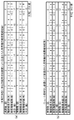
- FIG. (A) shows the number of binding noodle strings of instant noodles manufactured by the noodle string cutting device according to the present embodiment.
- (B) shows the number of bound noodle strings of instant noodles manufactured by the apparatus without chute members.
- the first noodle group consists of 7 noodle strings in which two noodle strings are bound. 2 sets of noodle strings with 3 noodle strings bound, 0 sets of noodle strings with 4 noodle strings bound, and a total of 9 noodle strings It was a pair.
- 11 sets of noodle strings with two noodle strings bound together, 0 sets of noodle strings with 3 noodle strings bound together, and 4 sets of noodle strings There were 0 sets of noodle strings worn, and the total number of binding noodle strings was 11 sets.
- the average number of bound noodle strings was 10.8.
- the first chute member 20a and the second chute member 20b are peeled off by the peeling teeth of the second scraper 40a and the fourth scraper 40b, respectively.
- the noodle strings 3b and the noodle strings 3d were arranged so as to correspond to the dropping positions.
- the configuration of the noodle string cutting device 1 is not limited to this.
- each of the first chute member 20a and the second chute member 20b corresponds to the drop position of the noodle strings 3a and noodle strings 3c that have been stripped off by the stripped teeth of the first scraper 30a and the third scraper 30b.
- positioned may be sufficient.
- FIG. 10 is a cross-sectional view illustrating an example of a schematic configuration of a noodle string cutting device 1 according to a modification of the present embodiment.
- the run direction of the noodle strings 3 is the width direction of the transport conveyor 500, the transport direction of the transport conveyor 500, the transport direction of the transport conveyor 500, and the transport in the order of the noodle strings 3d, 3c, 3b, and 3a. It becomes the width direction of the conveyor 500.
- the noodle strings are not provided with the first chute member 20a and the second chute member 20b, as compared with the configuration in which the noodle strings 3 are laminated so that all the swing directions of the noodle strings 3 are in the transport direction. Bonding between each other can be reduced.
- the noodle strip 3a and the noodle strip 3d stripped by the stripped tooth rows of the first scraper 30a and the fourth scraper 40b correspond to the drop positions of the noodle strip 3a. It is not limited to the configuration in which the first chute member 20a and the second chute member 20b are arranged. On the contrary, the first chute member 20a and the second chute member 20b are arranged corresponding to the dropping positions of the noodle strings 3b and the noodle strings 3d that have been peeled off by the peeling teeth of the second scraper 40a and the third scraper 30b, respectively. It may be configured.
- FIG. 11 is a cross-sectional view illustrating an example of a schematic configuration of a noodle string cutting device 1 according to a modification of the present embodiment.
- the noodle strings 3 are swung in the order of the noodle strings 3d, 3c, 3b, and 3a in the order of the conveyance conveyor 500, the conveyance conveyor 500, the conveyance conveyor 500, and the conveyance conveyor 500. It becomes the conveyance direction of the conveyor 500.
- the first chute member 20a is arranged so as to correspond to the dropping position of the noodle strip 3b stripped by the stripped tooth row of the second scraper 40a. It is not limited to.
- column of the 3rd scrape 30b may be sufficient. That is, it is only necessary that the first chute member 20a is provided so that at least two sets are stacked so that the deflection directions of the noodle strings 3 intersect each other.
- the noodle string cutting device 1 is not limited to a configuration in which two scrapers each having one stripped tooth row for one scraper are arranged for one cutting blade roll, for example, It is good also as a structure which arrange
- the stripped tooth row that is in contact with the cutting blade roll from the upstream side to the downstream side is replaced with the fourth stripped tooth row and the third stripped tooth row.
- a tooth row, a second stripped tooth row, and a first stripped tooth row are used.
- the first chute member 20a and / or the second chute member 20b is configured to change the swing direction so that the noodle strings 3 swing in the width direction of the conveyor 500.
- the noodle strings 3 that are in contact with the chute member are configured to change the direction of the noodle strings so that they are approximately 90 degrees with respect to the direction of vibration of the noodle strings 3 that are not in contact with the chute member.
- the deflection direction of the noodle strings 3 is not necessarily limited to the configuration in which the deflection direction is changed to be approximately 90 degrees as described above, and the noodle strings 3 that swing in the transport direction intersect with the deflection direction of the noodle strings. That's fine.
- the present invention is useful in a noodle strip cutting device that cuts out a plurality of noodle strips from a noodle strip.
- a plurality of noodle strings are cut out from a noodle strip to produce instant noodles, frozen noodles, and chilled noodles.
Landscapes
- Life Sciences & Earth Sciences (AREA)
- Engineering & Computer Science (AREA)
- Food Science & Technology (AREA)
- Health & Medical Sciences (AREA)
- Nutrition Science (AREA)
- Chemical & Material Sciences (AREA)
- Polymers & Plastics (AREA)
- Manufacturing And Processing Devices For Dough (AREA)
- Noodles (AREA)
- Details Of Cutting Devices (AREA)
Priority Applications (10)
| Application Number | Priority Date | Filing Date | Title |
|---|---|---|---|
| US15/030,974 US20160262406A1 (en) | 2013-11-08 | 2014-11-10 | Noodle string cutting device and raw noodles |
| CN201480059500.0A CN105658071B (zh) | 2013-11-08 | 2014-11-10 | 面条切割装置及生面 |
| MYPI2016701627A MY186525A (en) | 2013-11-08 | 2014-11-10 | Noodle string cutting device and raw noodles |
| KR1020167013901A KR102255056B1 (ko) | 2013-11-08 | 2014-11-10 | 면선 커팅 장치 및 생면 |
| BR112016009808-0A BR112016009808B1 (pt) | 2013-11-08 | 2014-11-10 | Dispositivo de corte de cordas de macarrão compreendendo elementos de calha |
| MX2016005587A MX395533B (es) | 2013-11-08 | 2014-11-10 | Dispositivo de corte de tiras de fideos y fideos crudos. |
| EP14860040.6A EP3066929B1 (en) | 2013-11-08 | 2014-11-10 | Noodle cutting machine and raw noodles |
| HK16108294.8A HK1220083B (en) | 2013-11-08 | 2014-11-10 | Noodle cutting machine and raw noodles |
| RU2016121405A RU2667160C2 (ru) | 2013-11-08 | 2014-11-10 | Устройство для нарезания нитей лапши и сырая лапша |
| PH12016500674A PH12016500674B1 (en) | 2013-11-08 | 2016-04-12 | Noodle string cutting device and raw noodles |
Applications Claiming Priority (2)
| Application Number | Priority Date | Filing Date | Title |
|---|---|---|---|
| JP2013-232502 | 2013-11-08 | ||
| JP2013232502A JP6242165B2 (ja) | 2013-11-08 | 2013-11-08 | 麺線切出し装置 |
Publications (1)
| Publication Number | Publication Date |
|---|---|
| WO2015068402A1 true WO2015068402A1 (ja) | 2015-05-14 |
Family
ID=53041195
Family Applications (1)
| Application Number | Title | Priority Date | Filing Date |
|---|---|---|---|
| PCT/JP2014/005635 Ceased WO2015068402A1 (ja) | 2013-11-08 | 2014-11-10 | 麺線切出し装置および生麺 |
Country Status (13)
| Country | Link |
|---|---|
| US (1) | US20160262406A1 (https=) |
| EP (1) | EP3066929B1 (https=) |
| JP (1) | JP6242165B2 (https=) |
| KR (1) | KR102255056B1 (https=) |
| CN (1) | CN105658071B (https=) |
| BR (1) | BR112016009808B1 (https=) |
| HU (1) | HUE054019T2 (https=) |
| MX (1) | MX395533B (https=) |
| MY (1) | MY186525A (https=) |
| PH (1) | PH12016500674B1 (https=) |
| RU (1) | RU2667160C2 (https=) |
| TW (1) | TWI572285B (https=) |
| WO (1) | WO2015068402A1 (https=) |
Cited By (2)
| Publication number | Priority date | Publication date | Assignee | Title |
|---|---|---|---|---|
| CN108283201A (zh) * | 2018-03-16 | 2018-07-17 | 范爱刚 | 溜面机 |
| CN112640933A (zh) * | 2020-12-01 | 2021-04-13 | 杭州衡美食品科技有限公司 | 一种输送稳定且保证软心层包裹效果的软心棒生产设备 |
Families Citing this family (6)
| Publication number | Priority date | Publication date | Assignee | Title |
|---|---|---|---|---|
| JP7226967B2 (ja) * | 2018-10-29 | 2023-02-21 | サンヨー食品株式会社 | 麺線切出し装置、麺類の製造装置、並びに麺類及び即席麺の製造方法 |
| JP7141912B2 (ja) * | 2018-10-29 | 2022-09-26 | サンヨー食品株式会社 | 麺線切出し装置、麺類の製造装置、並びに麺類及び即席麺の製造方法 |
| JP7325265B2 (ja) * | 2019-08-27 | 2023-08-14 | サンヨー食品株式会社 | 波状断面を有する麺線の製造方法 |
| CN110786353B (zh) * | 2019-11-10 | 2023-08-08 | 深圳厨奇自胜智能装备技术有限公司 | 一种面卷面片自动切取机器人以及面卷面片自动切取方法 |
| EP4082346B1 (en) * | 2019-12-23 | 2025-08-13 | Sanyo Foods Co., Ltd. | Noodle cutting device, noodle production device, noodle, and instant noodle production method |
| PH12022551490A1 (en) * | 2019-12-23 | 2023-11-06 | Sanyo Foods Co Ltd | Noodle string cutting device, noodle manufacturing device, and noodle and instant noodle manufacturing method |
Citations (8)
| Publication number | Priority date | Publication date | Assignee | Title |
|---|---|---|---|---|
| JPS57203787U (https=) | 1981-06-19 | 1982-12-25 | ||
| JPS5970485U (ja) * | 1982-11-01 | 1984-05-12 | ハウス食品工業株式会社 | 麺線切出し装置 |
| JPH075386U (ja) * | 1993-06-22 | 1995-01-27 | 日清食品株式会社 | 麺線処理装置 |
| JPH10313805A (ja) * | 1997-05-17 | 1998-12-02 | Yokoyama Seimen Kojo:Kk | 即席麺類の製造方法 |
| JPH11346641A (ja) * | 1998-04-09 | 1999-12-21 | Nissin Food Prod Co Ltd | 定長押出し麺線の製造装置及び製造方法 |
| JP2010187621A (ja) * | 2009-02-19 | 2010-09-02 | Nissin Foods Holdings Co Ltd | 束になった即席麺用生麺 |
| WO2010146635A1 (ja) * | 2009-06-16 | 2010-12-23 | 日清食品ホールディングス株式会社 | 製麺用切出装置 |
| WO2011158944A1 (ja) * | 2010-06-17 | 2011-12-22 | 日清食品ホールディングス株式会社 | 麺線処理装置及び処理方法 |
Family Cites Families (10)
| Publication number | Priority date | Publication date | Assignee | Title |
|---|---|---|---|---|
| JPS57203787A (en) | 1981-06-09 | 1982-12-14 | Arakawa Kako Kk | Gold-indium alloy plating method |
| JPS62138157A (ja) * | 1985-12-10 | 1987-06-20 | Fuji Seisakusho:Kk | 乾麺の製造方法及びこれに使用する器具 |
| JPH07184525A (ja) * | 1993-12-27 | 1995-07-25 | Keiichiro Murofushi | 麺線切断面付着防止装置 |
| JP3746087B2 (ja) * | 1994-09-16 | 2006-02-15 | エースコック株式会社 | 麺線切出し装置 |
| JPH09224546A (ja) * | 1996-02-26 | 1997-09-02 | Tomu:Kk | 麺線のウェーブ加工装置 |
| US6187358B1 (en) * | 1998-04-09 | 2001-02-13 | Nisshi Food Products Co., Ltd. | Method of and apparatus for producing extruded elongate pasta of substantially even lengths |
| IT249344Y1 (it) * | 2000-12-21 | 2003-04-14 | Imperia Trading S R L | Macchina ad uso domestico per la fabbricazione, il taglio e la conformazione di paste alimentari. |
| BRPI0913900B1 (pt) * | 2008-10-11 | 2018-09-11 | Nissin Foods Holdings Co Ltd | aparelho para corte e ejeção de talharins |
| JP4951012B2 (ja) * | 2009-02-19 | 2012-06-13 | 日清食品冷凍株式会社 | 製麺用切出装置及び、該装置を用いた麺類の製造法 |
| JP5817019B2 (ja) * | 2011-04-28 | 2015-11-18 | 日清食品ホールディングス株式会社 | 麺線切り出し装置 |
-
2013
- 2013-11-08 JP JP2013232502A patent/JP6242165B2/ja active Active
-
2014
- 2014-11-10 WO PCT/JP2014/005635 patent/WO2015068402A1/ja not_active Ceased
- 2014-11-10 RU RU2016121405A patent/RU2667160C2/ru active
- 2014-11-10 CN CN201480059500.0A patent/CN105658071B/zh active Active
- 2014-11-10 MY MYPI2016701627A patent/MY186525A/en unknown
- 2014-11-10 KR KR1020167013901A patent/KR102255056B1/ko active Active
- 2014-11-10 EP EP14860040.6A patent/EP3066929B1/en active Active
- 2014-11-10 TW TW103138882A patent/TWI572285B/zh active
- 2014-11-10 MX MX2016005587A patent/MX395533B/es unknown
- 2014-11-10 HU HUE14860040A patent/HUE054019T2/hu unknown
- 2014-11-10 BR BR112016009808-0A patent/BR112016009808B1/pt active IP Right Grant
- 2014-11-10 US US15/030,974 patent/US20160262406A1/en not_active Abandoned
-
2016
- 2016-04-12 PH PH12016500674A patent/PH12016500674B1/en unknown
Patent Citations (9)
| Publication number | Priority date | Publication date | Assignee | Title |
|---|---|---|---|---|
| JPS57203787U (https=) | 1981-06-19 | 1982-12-25 | ||
| JPS5970485U (ja) * | 1982-11-01 | 1984-05-12 | ハウス食品工業株式会社 | 麺線切出し装置 |
| JPH075386U (ja) * | 1993-06-22 | 1995-01-27 | 日清食品株式会社 | 麺線処理装置 |
| JPH10313805A (ja) * | 1997-05-17 | 1998-12-02 | Yokoyama Seimen Kojo:Kk | 即席麺類の製造方法 |
| JPH11346641A (ja) * | 1998-04-09 | 1999-12-21 | Nissin Food Prod Co Ltd | 定長押出し麺線の製造装置及び製造方法 |
| JP2010187621A (ja) * | 2009-02-19 | 2010-09-02 | Nissin Foods Holdings Co Ltd | 束になった即席麺用生麺 |
| WO2010146635A1 (ja) * | 2009-06-16 | 2010-12-23 | 日清食品ホールディングス株式会社 | 製麺用切出装置 |
| JP2011000001A (ja) * | 2009-06-16 | 2011-01-06 | Nissin Foods Holdings Co Ltd | 製麺用切出装置 |
| WO2011158944A1 (ja) * | 2010-06-17 | 2011-12-22 | 日清食品ホールディングス株式会社 | 麺線処理装置及び処理方法 |
Cited By (2)
| Publication number | Priority date | Publication date | Assignee | Title |
|---|---|---|---|---|
| CN108283201A (zh) * | 2018-03-16 | 2018-07-17 | 范爱刚 | 溜面机 |
| CN112640933A (zh) * | 2020-12-01 | 2021-04-13 | 杭州衡美食品科技有限公司 | 一种输送稳定且保证软心层包裹效果的软心棒生产设备 |
Also Published As
| Publication number | Publication date |
|---|---|
| MY186525A (en) | 2021-07-24 |
| RU2016121405A3 (https=) | 2018-03-19 |
| CN105658071A (zh) | 2016-06-08 |
| TW201517800A (zh) | 2015-05-16 |
| JP2015092837A (ja) | 2015-05-18 |
| EP3066929A4 (en) | 2017-05-10 |
| CN105658071B (zh) | 2018-08-07 |
| PH12016500674A1 (en) | 2016-05-30 |
| KR102255056B1 (ko) | 2021-05-21 |
| MX395533B (es) | 2025-03-25 |
| US20160262406A1 (en) | 2016-09-15 |
| EP3066929B1 (en) | 2020-12-23 |
| BR112016009808B1 (pt) | 2021-10-19 |
| JP6242165B2 (ja) | 2017-12-06 |
| HUE054019T2 (hu) | 2021-08-30 |
| RU2016121405A (ru) | 2017-12-13 |
| KR20160085790A (ko) | 2016-07-18 |
| MX2016005587A (es) | 2016-07-21 |
| RU2667160C2 (ru) | 2018-09-17 |
| PH12016500674B1 (en) | 2019-03-08 |
| TWI572285B (zh) | 2017-03-01 |
| BR112016009808A2 (https=) | 2017-08-01 |
| HK1220083A1 (zh) | 2017-04-28 |
| EP3066929A1 (en) | 2016-09-14 |
Similar Documents
| Publication | Publication Date | Title |
|---|---|---|
| JP6242165B2 (ja) | 麺線切出し装置 | |
| JP4625876B2 (ja) | 麺線剥離板及び麺線切出し装置 | |
| US9867380B2 (en) | Apparatus for cutting out noodle | |
| KR101927765B1 (ko) | 칼집형성수단을 갖는 꼬치 제조장치 | |
| JP6479128B2 (ja) | 麺線切出し装置および生麺 | |
| JP2016093145A (ja) | 麺線切出装置 | |
| JP2010166848A (ja) | 麺線切出し装置 | |
| JP3746087B2 (ja) | 麺線切出し装置 | |
| KR100962359B1 (ko) | 베이커리용 정형시스템 | |
| HK1220083B (en) | Noodle cutting machine and raw noodles | |
| WO2014014121A1 (ja) | 粗麺帯成形ロール装置 | |
| RU28842U1 (ru) | Устройство для резки на полосы кусков материала | |
| JP7141912B2 (ja) | 麺線切出し装置、麺類の製造装置、並びに麺類及び即席麺の製造方法 | |
| JP4255956B2 (ja) | 麺帯状マシュマロの麺線状切出し装置 | |
| JP5627933B2 (ja) | 油ちょう槽投入シュート | |
| RU2326576C2 (ru) | Устройство для перекрестной резки пластов продукта | |
| CN117279759A (zh) | 食物切割器和切割食物的方法 | |
| JPS62158442A (ja) | 太さや幅の異なる麺の製造法および製麺用回転切刃装置 | |
| WO2021130827A1 (ja) | 麺線切出し装置、麺類の製造装置、並びに麺類及び即席麺の製造方法 |
Legal Events
| Date | Code | Title | Description |
|---|---|---|---|
| 121 | Ep: the epo has been informed by wipo that ep was designated in this application |
Ref document number: 14860040 Country of ref document: EP Kind code of ref document: A1 |
|
| DPE1 | Request for preliminary examination filed after expiration of 19th month from priority date (pct application filed from 20040101) | ||
| WWE | Wipo information: entry into national phase |
Ref document number: 12016500674 Country of ref document: PH |
|
| REEP | Request for entry into the european phase |
Ref document number: 2014860040 Country of ref document: EP |
|
| WWE | Wipo information: entry into national phase |
Ref document number: 15030974 Country of ref document: US |
|
| WWE | Wipo information: entry into national phase |
Ref document number: MX/A/2016/005587 Country of ref document: MX |
|
| NENP | Non-entry into the national phase |
Ref country code: DE |
|
| REG | Reference to national code |
Ref country code: BR Ref legal event code: B01A Ref document number: 112016009808 Country of ref document: BR |
|
| ENP | Entry into the national phase |
Ref document number: 20167013901 Country of ref document: KR Kind code of ref document: A |
|
| WWE | Wipo information: entry into national phase |
Ref document number: IDP00201603782 Country of ref document: ID |
|
| ENP | Entry into the national phase |
Ref document number: 2016121405 Country of ref document: RU Kind code of ref document: A |
|
| ENP | Entry into the national phase |
Ref document number: 112016009808 Country of ref document: BR Kind code of ref document: A2 Effective date: 20160429 |