WO2015060023A1 - 画像記録装置 - Google Patents
画像記録装置 Download PDFInfo
- Publication number
- WO2015060023A1 WO2015060023A1 PCT/JP2014/073476 JP2014073476W WO2015060023A1 WO 2015060023 A1 WO2015060023 A1 WO 2015060023A1 JP 2014073476 W JP2014073476 W JP 2014073476W WO 2015060023 A1 WO2015060023 A1 WO 2015060023A1
- Authority
- WO
- WIPO (PCT)
- Prior art keywords
- liquid
- head
- intrusion prevention
- nozzle surface
- nozzle
- Prior art date
- Legal status (The legal status is an assumption and is not a legal conclusion. Google has not performed a legal analysis and makes no representation as to the accuracy of the status listed.)
- Ceased
Links
Images








Classifications
-
- B—PERFORMING OPERATIONS; TRANSPORTING
- B41—PRINTING; LINING MACHINES; TYPEWRITERS; STAMPS
- B41J—TYPEWRITERS; SELECTIVE PRINTING MECHANISMS, i.e. MECHANISMS PRINTING OTHERWISE THAN FROM A FORME; CORRECTION OF TYPOGRAPHICAL ERRORS
- B41J2/00—Typewriters or selective printing mechanisms characterised by the printing or marking process for which they are designed
- B41J2/005—Typewriters or selective printing mechanisms characterised by the printing or marking process for which they are designed characterised by bringing liquid or particles selectively into contact with a printing material
- B41J2/01—Ink jet
- B41J2/135—Nozzles
- B41J2/165—Prevention or detection of nozzle clogging, e.g. cleaning, capping or moistening for nozzles
- B41J2/16505—Caps, spittoons or covers for cleaning or preventing drying out
- B41J2/16508—Caps, spittoons or covers for cleaning or preventing drying out connected with the printer frame
-
- B—PERFORMING OPERATIONS; TRANSPORTING
- B41—PRINTING; LINING MACHINES; TYPEWRITERS; STAMPS
- B41J—TYPEWRITERS; SELECTIVE PRINTING MECHANISMS, i.e. MECHANISMS PRINTING OTHERWISE THAN FROM A FORME; CORRECTION OF TYPOGRAPHICAL ERRORS
- B41J2/00—Typewriters or selective printing mechanisms characterised by the printing or marking process for which they are designed
- B41J2/005—Typewriters or selective printing mechanisms characterised by the printing or marking process for which they are designed characterised by bringing liquid or particles selectively into contact with a printing material
- B41J2/01—Ink jet
- B41J2/135—Nozzles
- B41J2/165—Prevention or detection of nozzle clogging, e.g. cleaning, capping or moistening for nozzles
- B41J2/16517—Cleaning of print head nozzles
- B41J2/1652—Cleaning of print head nozzles by driving a fluid through the nozzles to the outside thereof, e.g. by applying pressure to the inside or vacuum at the outside of the print head
- B41J2/16526—Cleaning of print head nozzles by driving a fluid through the nozzles to the outside thereof, e.g. by applying pressure to the inside or vacuum at the outside of the print head by applying pressure only
-
- B—PERFORMING OPERATIONS; TRANSPORTING
- B41—PRINTING; LINING MACHINES; TYPEWRITERS; STAMPS
- B41J—TYPEWRITERS; SELECTIVE PRINTING MECHANISMS, i.e. MECHANISMS PRINTING OTHERWISE THAN FROM A FORME; CORRECTION OF TYPOGRAPHICAL ERRORS
- B41J2/00—Typewriters or selective printing mechanisms characterised by the printing or marking process for which they are designed
- B41J2/005—Typewriters or selective printing mechanisms characterised by the printing or marking process for which they are designed characterised by bringing liquid or particles selectively into contact with a printing material
- B41J2/01—Ink jet
- B41J2/135—Nozzles
- B41J2/165—Prevention or detection of nozzle clogging, e.g. cleaning, capping or moistening for nozzles
- B41J2/16585—Prevention or detection of nozzle clogging, e.g. cleaning, capping or moistening for nozzles for paper-width or non-reciprocating print heads
- B41J2/16588—Print heads movable towards the cleaning unit
-
- B—PERFORMING OPERATIONS; TRANSPORTING
- B41—PRINTING; LINING MACHINES; TYPEWRITERS; STAMPS
- B41J—TYPEWRITERS; SELECTIVE PRINTING MECHANISMS, i.e. MECHANISMS PRINTING OTHERWISE THAN FROM A FORME; CORRECTION OF TYPOGRAPHICAL ERRORS
- B41J2/00—Typewriters or selective printing mechanisms characterised by the printing or marking process for which they are designed
- B41J2/005—Typewriters or selective printing mechanisms characterised by the printing or marking process for which they are designed characterised by bringing liquid or particles selectively into contact with a printing material
- B41J2/01—Ink jet
- B41J2/17—Ink jet characterised by ink handling
- B41J2/1721—Collecting waste ink; Collectors therefor
-
- B—PERFORMING OPERATIONS; TRANSPORTING
- B41—PRINTING; LINING MACHINES; TYPEWRITERS; STAMPS
- B41J—TYPEWRITERS; SELECTIVE PRINTING MECHANISMS, i.e. MECHANISMS PRINTING OTHERWISE THAN FROM A FORME; CORRECTION OF TYPOGRAPHICAL ERRORS
- B41J2/00—Typewriters or selective printing mechanisms characterised by the printing or marking process for which they are designed
- B41J2/005—Typewriters or selective printing mechanisms characterised by the printing or marking process for which they are designed characterised by bringing liquid or particles selectively into contact with a printing material
- B41J2/01—Ink jet
- B41J2/135—Nozzles
- B41J2/165—Prevention or detection of nozzle clogging, e.g. cleaning, capping or moistening for nozzles
- B41J2/16517—Cleaning of print head nozzles
- B41J2/16535—Cleaning of print head nozzles using wiping constructions
- B41J2002/1655—Cleaning of print head nozzles using wiping constructions with wiping surface parallel with nozzle plate and mounted on reels, e.g. cleaning ribbon cassettes
-
- B—PERFORMING OPERATIONS; TRANSPORTING
- B41—PRINTING; LINING MACHINES; TYPEWRITERS; STAMPS
- B41J—TYPEWRITERS; SELECTIVE PRINTING MECHANISMS, i.e. MECHANISMS PRINTING OTHERWISE THAN FROM A FORME; CORRECTION OF TYPOGRAPHICAL ERRORS
- B41J25/00—Actions or mechanisms not otherwise provided for
- B41J2025/008—Actions or mechanisms not otherwise provided for comprising a plurality of print heads placed around a drum
Definitions
- the present invention relates to an image recording apparatus, and more particularly to an image recording apparatus including a droplet discharge head configured by connecting a plurality of head modules.
- an ink jet recording apparatus that forms an image by ejecting ink from a head onto a transported recording medium.
- a plurality of short heads (head modules) having a nozzle row length less than the width of the recording medium are connected and extended in the main scanning direction.
- a droplet discharge head (line head) having a head configuration is provided.
- the droplet discharge head configured by connecting a plurality of head modules in this way has a gap on the nozzle surface due to its structure. That is, since the nozzle surfaces of the droplet discharge head are also formed by connecting the nozzle surfaces of adjacent head modules, a gap is generated at the joint portion of the head modules. If such a gap exists on the nozzle surface, there is a problem that when the pressure purge is performed, the pressure purged ink enters the gap. When ink enters the gap, the ink accumulates in the gap, and in the worst case, the head life and reliability, the printing performance is lowered, and the recording medium is damaged.
- Patent Document 1 describes that the ink entering the gap between the nozzle surfaces is effectively absorbed by the absorber by arranging the absorber so as to enter the gap between the nozzle surfaces.
- Patent Document 1 the absorber is arranged in the gap on the nozzle surface while avoiding the nozzle opening. However, it is very difficult to put the absorber in the minute gap, and the absorber accumulates ink (liquid). Therefore, there is a problem that the absorber itself needs to be cleaned.
- the present invention has been made in view of such circumstances, and image recording capable of preventing liquid overflowing from the nozzles from entering the gap between the head modules when the droplet discharge head is pressurized and purged.
- An object is to provide an apparatus.
- the first aspect is a droplet in which a plurality of head modules each having a nozzle surface on which a plurality of nozzles for discharging liquid are arranged are fixed by a head module support member and connected to each other, and the nozzle surfaces are inclined with respect to a horizontal plane.
- the receiving member that receives the liquid discharged from the nozzle and the receiving member is in contact with the droplet discharge head during the pressure purge and pressurizes
- a liquid intrusion prevention pad that prevents liquid discharged by purging from entering between the head modules, and the liquid intrusion prevention pad is formed of a non-absorbing material that does not absorb liquid, and the pressure purge is performed by tilting the nozzle surface.
- This is an image recording apparatus having a flow path for collecting the liquid ejected by the above.
- the “horizontal plane” here refers to a plane extending in a direction perpendicular to the direction of gravity.
- the receiving member for receiving the liquid discharged from the nozzle when performing the pressure purge is provided with the liquid intrusion prevention pad for preventing the liquid from entering during the pressure purge.
- the liquid intrusion prevention pad is formed of a material that does not absorb liquid.
- the liquid intrusion prevention pad has a flow path for collecting the liquid discharged by the pressure purge. That is, the liquid intrusion prevention pad is formed of a non-absorbing material that does not absorb liquid, and has a flow path for collecting the liquid discharged by the pressure purge due to the inclination of the nozzle surface. Since the liquid is collected at an arbitrary position of the support member, liquid can be prevented from entering between the head modules.
- liquid can be prevented from entering between the head modules by the pressure purge, and the long life and reliability of the droplet discharge head can be guaranteed.
- the ink intrusion prevention pad according to this aspect does not require positioning accuracy, the head modules can be blocked very easily.
- the liquid intrusion prevention pad is a gap provided at a position of the head module support member, and has a flow path in which the liquid discharged by the pressure purge is collected. And a plurality of pads that block the gap between the nozzle surface on the lower side in the gravitational direction of the nozzle surface provided to be inclined with respect to the horizontal plane and the head module support member with a non-flow path.
- the “gravity direction lower side” herein refers to the gravity direction side
- the “gravity direction upper side” refers to the side in the direction opposite to the gravity direction.
- the liquid intrusion prevention pad provides the gap between the nozzle surface on the lower side in the gravitational direction of the nozzle surface that is inclined with respect to the horizontal plane and the head module support member at a position that is not between the head modules. Except for the created channel, it is closed. Thereby, since the liquid discharged by the pressure purge is collected at an arbitrary position, it is possible to prevent the liquid from entering between the head modules.
- the liquid intrusion prevention pad is a gap between the nozzle surface on the lower side in the gravitational direction of the nozzle surface provided to be inclined with respect to the horizontal plane and the head module support member. Is a series of pads that block the liquid and have a flow path for collecting the liquid discharged by pressure purge on the non-contact surface to the droplet discharge head.
- the liquid intrusion prevention pad has a flow path that collects the liquid discharged by the pressure purge by closing all gaps between the nozzle surface on the lower side in the gravitational direction of the nozzle surface and the head module support member that are inclined with respect to the horizontal plane. Therefore, as compared with the second aspect, it is possible to completely prevent the liquid from entering between the head modules in the mode that travels through the gap between the nozzle surface and the head module support member.
- the liquid intrusion prevention pad is a liquid whose upper end surface in the gravity direction with respect to the droplet discharge head is discharged into the flow path by pressure purge. It is the aspect formed in the inclination which guide
- the end surface on the upper side in the gravity direction of the liquid intrusion prevention pad is formed to be inclined.
- the liquid intrusion prevention pad includes a nozzle surface on the upper side in the gravity direction of the nozzle surface provided to be inclined with respect to the horizontal plane. It is an aspect which further has a series of pads which block the gap with the head module support member.
- the gap between the nozzle surface on the lower side in the gravity direction of the nozzle surface provided to be inclined with respect to the horizontal plane and the head module support member is also closed with a liquid intrusion prevention pad. This further prevents liquid from entering between the head modules.
- the sixth aspect is an aspect in which in the image recording apparatus according to any one of the second to fifth aspects, two or more flow paths are provided for one head module.
- a seventh aspect is an aspect in which the liquid intrusion prevention pad is formed of an elastic body in the image recording apparatus according to any one of the first to sixth aspects.
- the liquid intrusion prevention pad is made of an elastic body, the gap between the nozzle surface and the head module support member can be closed with high sealing performance. Further, it is possible to prevent the liquid intrusion prevention pad from damaging the nozzle surface.
- the eighth aspect is an aspect in which, in the image recording apparatus according to any one of the first to seventh aspects, the end surface of the liquid intrusion prevention pad is hydrophilized.
- the liquid collecting ability is further improved.
- a ninth aspect is an aspect in which the liquid intrusion prevention pad is fixed to the receiving member via a support member in the image recording apparatus according to any one of the first to eighth aspects.
- the receiving member includes a moisturizing cap that moisturizes the nozzle surface, and the liquid discharged from the nozzle when performing the pressure purge is It is the aspect received inside a receiving member.
- the present invention it is possible to prevent the liquid overflowing from the nozzles from entering the gap between the head modules when performing a pressure purge of the droplet discharge head.
- FIG. 1 is an overall configuration diagram of an ink jet recording apparatus. It is a top view which shows the structural example of the inkjet head shown in FIG.
- FIG. 3 is a partially enlarged view of FIG. 2.
- FIG. 3 is a plan perspective view of the head module shown in FIG. 2. It is a side view which shows the drawing part of an inkjet recording device. It is a front view which shows the drawing part of an inkjet recording device. It is a top view which shows schematic structure of the drawing part of an inkjet recording device. It is side surface sectional drawing which shows an inkjet head and a receiving member. It is side surface sectional drawing which shows an inkjet head and a receiving member. It is the top view which looked at the receiving member from the upper surface.
- FIG. 14 is a cross-sectional view taken along line 14-14 of FIG. It is explanatory drawing which shows a head module and the liquid penetration
- FIG. 16 is a cross-sectional view taken along line 16-16 in FIG. It is explanatory drawing which shows a head module and the liquid penetration
- FIG. 18 is a cross-sectional view taken along line 18-18 in FIG.
- FIG. 20 is a cross-sectional view taken along line 20-20 in FIG. It is explanatory drawing which shows a head module and the liquid penetration
- FIG. 22 is a cross-sectional view taken along line 22-22 of FIG.
- FIG. 1 is a configuration diagram showing the overall configuration of the ink jet recording apparatus.
- the inkjet recording apparatus 10 includes a plurality of colors from inkjet heads 72M, 72K, 72C, and 72Y on a recording medium 24 (sometimes referred to as “paper” for convenience) held on an impression cylinder (drawing drum 70) of the drawing unit 16.
- a recording medium 24 sometimes referred to as “paper” for convenience
- a treatment liquid here, an aggregating treatment liquid
- This is an on-demand type image forming apparatus to which a two-liquid reaction (aggregation) method for forming an image on a recording medium 24 by reacting a treatment liquid and an ink liquid is applied.
- the ink jet recording apparatus 10 mainly includes a paper feed unit 12, a processing liquid application unit 14, a drawing unit 16, a drying unit 18, a fixing unit 20, and a discharge unit 22.
- the paper supply unit 12 is a mechanism that supplies the recording medium 24 to the treatment liquid application unit 14, and a recording medium 24 that is a sheet is stacked on the paper supply unit 12.
- the paper feed unit 12 is provided with a paper feed tray 50, and the recording medium 24 is fed from the paper feed tray 50 to the processing liquid application unit 14 one by one.
- a plurality of types of recording media 24 having different paper types and sizes (paper sizes) can be used as the recording medium 24.
- a mode is also possible in which a plurality of paper trays (not shown) are provided in the paper feed unit 12 to separately collect various recording media and the paper to be sent to the paper feed tray 50 is automatically switched from among the plurality of paper trays.
- a mode is also possible in which the operator selects or replaces the paper tray as necessary.
- a sheet (cut paper) is used as the recording medium 24, but a configuration in which continuous paper (roll paper) is cut to a required size and fed is also possible.
- the processing liquid application unit 14 is a mechanism that applies the processing liquid to the recording surface of the recording medium 24.
- the treatment liquid contains a color material aggregating agent that agglomerates the color material (pigment in this example) applied in the ink provided by the drawing unit 16, and the ink comes into contact with the colorant when the treatment liquid comes into contact with the ink. And the solvent are promoted.
- the treatment liquid application unit 14 includes a paper feed drum 52, a treatment liquid drum 54, and a treatment liquid application device 56.
- the treatment liquid drum 54 is a drum that holds and rotates and conveys the recording medium 24.
- the processing liquid drum 54 is provided with a claw-shaped holding means (gripper) 55 on the outer peripheral surface thereof, and the recording medium 24 is sandwiched between the claw of the holding means 55 and the peripheral surface of the processing liquid drum 54 to thereby remove the recording medium 24.
- the tip can be held.
- the treatment liquid drum 54 may be provided with suction holes on the outer peripheral surface thereof and connected to suction means for suction from the suction holes. As a result, the recording medium 24 can be held in close contact with the peripheral surface of the treatment liquid drum 54.
- a processing liquid coating device 56 is provided outside the processing liquid drum 54 so as to face the peripheral surface thereof.
- the processing liquid coating device 56 includes a processing liquid container in which the processing liquid is stored, an anix roller partially immersed in the processing liquid in the processing liquid container, and the recording medium 24 on the anix roller and the processing liquid drum 54. And a rubber roller that transfers the measured processing liquid to the recording medium 24. According to the processing liquid application device 56, the processing liquid can be applied to the recording medium 24 while being measured.
- the recording medium 24 to which the processing liquid is applied by the processing liquid applying unit 14 is transferred from the processing liquid drum 54 to the drawing drum 70 of the drawing unit 16 through the intermediate transport unit 26.
- the drawing unit 16 includes a drawing drum (second transport body) 70, a sheet pressing roller 74, and inkjet heads 72M, 72K, 72C, and 72Y.
- the drawing drum 70 includes a claw-shaped holding means (gripper) 71 on the outer peripheral surface thereof, like the processing liquid drum 54.
- the recording medium 24 fixed to the drawing drum 70 is conveyed with the recording surface facing outward, and ink is applied to the recording surface from the inkjet heads 72M, 72K, 72C, 72Y.
- the inkjet heads 72M, 72K, 72C, 72Y are preferably full-line inkjet recording heads (inkjet heads) each having a length corresponding to the maximum width of the image forming area in the recording medium 24. On the ink ejection surface, a nozzle row in which a plurality of nozzles for ink ejection are arranged over the entire width of the image forming area is formed.
- Each inkjet head 72M, 72K, 72C, 72Y is installed so as to extend in a direction orthogonal to the conveyance direction of the recording medium 24 (the rotation direction of the drawing drum 70).
- the droplets of the corresponding color ink are ejected from the respective ink jet heads 72M, 72K, 72C, 72Y toward the recording surface of the recording medium 24 held tightly on the drawing drum 70.
- the ink comes into contact with the treatment liquid previously applied to the recording surface, and the color material (pigment) dispersed in the ink is aggregated to form a color material aggregate. Thereby, the color material flow on the recording medium 24 is prevented, and an image is formed on the recording surface of the recording medium 24.
- CMYK standard colors four colors
- the combination of ink colors and the number of colors is not limited to this embodiment, and light ink, dark ink, and special colors are used as necessary.
- Ink may be added.
- an inkjet head that discharges light-colored ink such as light cyan and light magenta, and the arrangement order of the color heads is not particularly limited.
- the recording medium 24 on which the image is formed by the drawing unit 16 is transferred from the drawing drum 70 to the drying drum 76 of the drying unit 18 through the intermediate conveyance unit 28.
- the drying unit 18 is a mechanism for drying moisture contained in the solvent separated by the color material aggregation action, and includes a drying drum 76 and a solvent drying device 78 as shown in FIG.
- the drying drum 76 is provided with a claw-shaped holding means (gripper) 77 on its outer peripheral surface, like the processing liquid drum 54, so that the leading end of the recording medium 24 can be held by the holding means 77.
- a claw-shaped holding means (gripper) 77 on its outer peripheral surface, like the processing liquid drum 54, so that the leading end of the recording medium 24 can be held by the holding means 77.
- the solvent drying device 78 is disposed at a position facing the outer peripheral surface of the drying drum 76, and includes a plurality of IR heaters 82 and hot air jet nozzles 80 disposed between the IR heaters 82, respectively.
- the surface temperature of the drying drum 76 is set to 50 ° C. or higher. Drying is accelerated by heating from the back surface of the recording medium 24, and image destruction during fixing can be prevented.
- the upper limit of the surface temperature of the drying drum 76 is not particularly limited, but from the viewpoint of safety of maintenance work such as cleaning ink adhering to the surface of the drying drum 76 (preventing burns due to high temperature). It is preferably set to 75 ° C. or lower (more preferably 60 ° C. or lower).
- the recording drum 24 is held on the outer peripheral surface of the drying drum 76 so that the recording surface of the recording medium 24 faces outward (that is, in a state where the recording surface of the recording medium 24 is convex), and is dried while being rotated and conveyed. By doing so, it is possible to prevent the recording medium 24 from being wrinkled or lifted, and to reliably prevent uneven drying due to these.
- the recording medium 24 that has been dried by the drying unit 18 is transferred from the drying drum 76 to the fixing drum 84 of the fixing unit 20 via the intermediate conveyance unit 30.
- the fixing unit 20 includes a fixing drum 84, a halogen heater 86, a fixing roller 88, and an inline sensor 90.
- the fixing drum 84 includes a claw-shaped holding unit (gripper) 85 on its outer peripheral surface, and the holding unit 85 can hold the leading end of the recording medium 24.
- the recording medium 24 With the rotation of the fixing drum 84, the recording medium 24 is conveyed with the recording surface facing outward.
- the recording surface is preheated by the halogen heater 86, fixed by the fixing roller 88, and by the inline sensor 90. Inspection is performed.
- the halogen heater 86 is controlled to a predetermined temperature (for example, 180 ° C.). Thereby, the recording medium 24 is preheated.
- the fixing roller 88 is a roller member for heating and pressurizing the dried ink to weld the self-dispersing thermoplastic resin fine particles in the ink to form a film of the ink.
- the fixing roller 88 is configured to heat and press the recording medium 24. Composed.
- the fixing roller 88 is disposed so as to be in pressure contact with the fixing drum 84, and constitutes a nip roller with the fixing drum 84.
- the recording medium 24 is sandwiched between the fixing roller 88 and the fixing drum 84 and nipped at a predetermined nip pressure (for example, 0.15 MPa), and a fixing process is performed.
- a predetermined nip pressure for example, 0.15 MPa
- the fixing roller 88 is constituted by a heating roller in which a halogen lamp is incorporated in a metal pipe such as aluminum having good heat conductivity, and is controlled to a predetermined temperature (for example, 60 to 80 ° C.).
- a predetermined temperature for example, 60 to 80 ° C.
- only one fixing roller 88 is provided.
- a configuration in which a plurality of fixing rollers 88 are provided may be used depending on the thickness of the image layer and the Tg characteristics of the thermoplastic resin fine particles.
- the in-line sensor 90 is a measuring means for measuring a check pattern, a moisture content, a surface temperature, a glossiness, and the like for an image fixed on the recording medium 24, and a CCD line sensor or the like is applied.
- the thermoplastic resin fine particles in the thin image layer formed by the drying unit 18 are heated and pressurized by the fixing roller 88 and melted. Can be fixed and fixed. Further, by setting the surface temperature of the fixing drum 84 to 50 ° C. or higher, drying is promoted by heating the recording medium 24 held on the outer peripheral surface of the fixing drum 84 from the back surface, thereby preventing image destruction during fixing. In addition, the image intensity can be increased by the effect of increasing the image temperature.
- the image is irradiated with UV at the fixing unit equipped with a UV irradiation lamp.
- the monomer can be cured and polymerized to improve the image strength.
- a discharge unit 22 is provided following the fixing unit 20.
- the discharge unit 22 includes a discharge tray 92, and a transfer drum 94, a conveyance belt 96, and a tension roller 98 are provided between the discharge tray 92 and the fixing drum 84 of the fixing unit 20 so as to be in contact therewith. It has been.
- the recording medium 24 is sent to the conveying belt 96 by the transfer drum 94 and discharged to the discharge tray 92.
- the ink jet recording apparatus 10 of this example includes an ink storage / loading unit for supplying ink to the ink jet heads 72M, 72K, 72C, and 72Y, processing liquid, in addition to the above configuration.
- a head maintenance unit for supplying the processing liquid to the applying unit 14 and cleaning the ink jet heads 72M, 72K, 72C and 72Y (wiping, purging, nozzle suction, etc. of the nozzle surface), and on the paper transport path Are provided with a position detection sensor for detecting the position of the recording medium 24 and a temperature sensor for detecting the temperature of each part of the apparatus.
- FIG. 2 is a plan view showing a structural example of the inkjet head 72, and is a view of the inkjet head 72 as seen from the nozzle surface 72A side.
- FIG. 3 is a partially enlarged view of FIG.
- a plurality of nozzles (not shown in FIG. 2) are provided over a length corresponding to the entire width of the recording medium.
- Each head module 72-i is supported by a head module support member 72B from both sides of the inkjet head 72 in the short direction. Further, both end portions of the inkjet head 72 in the longitudinal direction are supported by a head support member 72D.
- each head module 72-i (nth head module 72-n) has a structure in which a plurality of nozzles are arranged in a matrix.
- an oblique solid line denoted by reference numeral 151A represents a nozzle row in which a plurality of nozzles are arranged in a row.
- FIG. 4A is a plan perspective view of the head module 72-i
- FIG. 4B is an enlarged view of a part thereof.
- the head module 72-i of this example includes a plurality of inks composed of nozzles 151 that are ink discharge ports, pressure chambers 152 corresponding to the nozzles 151, and the like.
- the chamber units (droplet ejection elements as recording element units) 153 have a structure in which they are arranged in a staggered matrix (two-dimensionally), thereby making the head longitudinal direction (perpendicular to the transport direction of the recording medium 24).
- the density of the substantial nozzle interval (projection nozzle pitch) projected so as to be aligned along the direction (main scanning direction) is achieved.
- the pressure chamber 152 provided corresponding to each nozzle 151 has a substantially square planar shape, the nozzle 151 is provided at one of the diagonal corners, and the supply port 154 is provided at the other. ing.
- the shape of the pressure chamber 152 is not limited to this example, and the planar shape may have various forms such as a quadrangle (rhombus, rectangle, etc.), a pentagon, a hexagon, other polygons, a circle, and an ellipse.
- the ink chamber units 153 having such a structure are arranged in a fixed manner along a row direction along the main scanning direction and an oblique column direction having a constant angle ⁇ that is not orthogonal to the main scanning direction.
- the high-density nozzle head of this example is realized.
- each nozzle 151 can be handled equivalently as a linear arrangement with a constant pitch P.
- the number of nozzle rows projected so as to be aligned in the main scanning direction is 2400 per inch (2400 nozzles / inch).
- FIG. 5 is a side view showing a drawing unit of the ink jet recording apparatus
- FIG. 6 is a front view showing the drawing unit of the ink jet recording apparatus
- FIG. 7 is a top view showing a schematic configuration of the drawing unit of the ink jet recording apparatus.
- the drawing drum 70 is rotatably provided with both ends of the rotating shaft 218 being pivotally supported by a pair of bearings 222 (see FIG. 6).
- the pair of bearings 222 are provided on the main body frame 220 of the ink jet recording apparatus, and the drawing drum 70 is attached horizontally by supporting both ends of the rotating shaft 218 on the pair of bearings 222.
- the rotation shaft 218 is attached in parallel to the installation surface.
- the four inkjet heads 72M, 72K, 72C, and 72Y are arranged radially on the concentric circle with the rotation axis 218 of the drawing drum 70 as the center, and are attached to the head support frame 240 as shown in FIG. And arranged around the drawing drum 70.
- the head support frame 240 includes a pair of side plates 242L and 242R provided orthogonal to the rotation shaft 218 of the drawing drum 70, and a connecting frame 244 that connects the pair of side plates 242L and 242R at the upper end. ing.
- the pair of side plates 242L and 242R are formed in a plate shape and are disposed so as to face each other with the drawing drum 70 interposed therebetween.
- Mounting portions 246M, 246K, 246C, and 246Y for mounting the inkjet heads 72M, 72K, 72C, and 72Y are provided inside the pair of side plates 242L, 242R (in FIG. 6, for the sake of convenience, the mounting portions are mounted). Only 246Y is shown).
- the mounting portions 246C, 246M, 246Y, and 246K are radially arranged on the concentric circle with the rotation axis 218 of the drawing drum 70 as a center at a constant interval.
- Each inkjet head 72M, 72K, 72C and 72Y has attached portions 248M, 248K, 248C and 248Y (only the attached portion 248Y is shown in FIG. 6 for the sake of convenience) formed at both ends thereof.
- And 246Y are attached to the head support frame 240. Then, by attaching to the head support frame 240, the inkjet heads 72M, 72K, 72C and 72Y are radially arranged on the concentric circle with the rotation axis 218 of the drawing drum 70 as the center.
- the head support frame 240 is guided by a guide rail (not shown) and is provided so as to be slidable in parallel with the rotation shaft 218 of the drawing drum 70. Then, it is driven by a linear drive mechanism (for example, a feed screw mechanism or the like) not shown, and between the “image recording position” indicated by a solid line in FIG. 6 and the “retraction position (maintenance position)” indicated by a broken line in FIG. Moving.
- a linear drive mechanism for example, a feed screw mechanism or the like
- the inkjet heads 72M, 72K, 72C, and 72Y are arranged around the drawing drum 70 when the head support frame 240 is positioned at the image recording position, and are ready for image recording.
- the retreat position is set to a position where each of the inkjet heads 72M, 72K, 72C, and 72Y retracts from the drawing drum 70.
- a maintenance unit 250 for maintaining each of the inkjet heads 72M, 72K, 72C, and 72Y is provided at the retracted position.
- the maintenance unit 250 includes receiving members (caps) 280M, 280K, 280C, and 280Y that cover the nozzle surfaces of the inkjet heads 72M, 72K, 72C, and 72Y (only the receiving member 280Y is shown in FIG. 6 for convenience). Yes. When the apparatus is stopped for a long time, the nozzle surface is covered with the receiving members 280M, 280K, 280C and 280Y. Thereby, non-ejection due to drying is prevented.
- the receiving members 280M, 280K, 280C, and 280Y are provided with a pressurization and suction mechanism (not shown) so that the inside of the nozzle can be pressurized and sucked.
- the receiving members 280M, 280K, 280C, and 280Y are provided with a cleaning liquid supply mechanism (not shown) so that the cleaning liquid can be supplied to the inside.
- FIGS. 8 and 9 are side sectional views showing the inkjet head 72Y and the receiving member 280Y.
- FIG. 10 is an example of the receiving member 280Y of FIGS. 8 and 9 as viewed from above.
- the receiving member 280Y is provided with a moisturizing cap 282.
- the moisturizing cap 282 is supplied with a moisturizing liquid (not shown).
- the inkjet head 72Y is configured to move up and down at the retracted position.
- the moisture retention cap 282 is a member that covers the nozzle surface 72A of the inkjet head 72Y and caps the inkjet head 72Y. As shown in FIG. 9, when the inkjet recording apparatus 10 is not used for a long period of time, the moisturizing cap 282 covers the nozzle surface 72A of the inkjet head 72Y. Thereby, it can prevent that a solvent evaporates from a nozzle and can prevent that a foreign material adheres to 72 A of nozzle surfaces. For example, pure water is used as the moisturizing liquid.
- the inside of the head is pressurized with the nozzle surface 72A of the inkjet head 72Y covered with the moisture retaining cap 282, and the ink is discharged from the nozzle. Thereby, the purged ink can be collected by the moisture retention cap 282.
- the moisturizing cap includes a moisturizing liquid supply device that supplies moisturizing liquid, a waste liquid device that drains the moisturizing liquid in the moisturizing cap, and the like.
- the inkjet heads 72M, 72K, 72C, and 72Y are provided such that the nozzle surfaces are inclined with respect to the horizontal plane.
- the ink that has entered the gap between the nozzle surface 72A and the head module support member 72B tends to enter the space between the head modules 73 through the gap between the nozzle surface 72A and the head module support member 72B.
- the nozzle surface being inclined with respect to the horizontal plane means that the nozzle surface is not parallel to the horizontal plane, and is 1 ° or more and 89 ° or less on the horizontal plane. In other words, it is inclined.
- the liquid intrusion prevention pads 290a and 290b are required to be provided so as not to block the nozzle 151 of the nozzle surface 72A.
- FIG. 10 is a top view showing the receiving member 280Y of FIGS. 8 and 9 as viewed from above, and including the liquid intrusion prevention pads 290a and 290b.
- 13 and 14 show the head module 72-i and the liquid intrusion prevention pads 290a and 290b.
- FIG. 13 shows the head module 72-i and the liquid intrusion prevention pads 290a and 290b from below.
- FIG. 14 is a bottom view seen, and FIG. 14 is a cross-sectional view taken along line 14-14 of FIG.
- the droplet discharge head 72Y is provided with a nozzle surface 72A inclined with respect to a horizontal plane.
- the receiving member 280Y that receives ink when performing the pressure purge of the droplet discharge head 72Y is provided in parallel to the nozzle surface 72A. That is, the receiving member 280Y is provided to be inclined with respect to the horizontal plane in the same manner as the nozzle surface 72A.
- the receiving member 280Y is provided with the liquid intrusion prevention pad 290a on the lower side in the gravity direction and the liquid intrusion prevention pad 290b on the upper side in the gravity direction when the receiving member 280Y is inclined with respect to the horizontal plane. It is inclined to.
- the liquid intrusion prevention pads 290a and 290b are fixed to the receiving member 280Y via the supporting members 292a and 292b. As shown in FIG. 9, since the support members 292a and 292b have to make the droplet discharge head 72Y and the liquid intrusion prevention pads 290a and 290b closely contact each other without any gaps, they have a certain restoring force such as a spring. A member that can press the liquid intrusion prevention pads 290a and 290b against the droplet discharge head 72Y with force is preferable.
- the moisture retaining cap 282 is provided on the receiving member 280Y, and the moisture retaining cap 282 covers the nozzle surface 72A.
- the liquid intrusion prevention pads 290a and 290b receive the receiving member 280Y so as to close the gap 100 between the nozzle surface 72A and the head module support member 72B when the receiving member 280Y is brought into contact with the moisture retaining cap 282 to perform the pressure purge. Is provided.
- the liquid intrusion prevention pad 290a on the lower side in the gravity direction has a flow path 291.
- the liquid intrusion prevention pad 290a on the lower side in the gravity direction has a plurality of liquid intrusion prevention pads arranged with a gap.
- the ink attached to the nozzle surface 72A by the pressure purge is collected in an arbitrary position of the head module support member 72B by the flow path 291 and discarded inside the receiving member 280Y.
- the flow path is not located between the head modules 73. It is necessary to provide the liquid intrusion prevention pad 290a so as to have 291.
- the liquid intrusion prevention pad 290b on the upper side in the gravity direction is provided at a position where the gap 100 between the nozzle surface 72A and the head module support member 72B is closed by one pad.
- the liquid intrusion prevention pad 290b on the upper side in the gravitational direction closes the gap 100 on the upper side in the gravitational direction between the nozzle surface 72A and the head module support member 72B. It is difficult for ink to flow into the gap 100 on the side. Therefore, the upstream liquid intrusion prevention pad 290b is preferably provided, but may not be provided.
- the liquid intrusion prevention pads 290a and 290b are preferably made of a material (elastic body) having flexibility that does not damage the head module 72-i. .
- the liquid intrusion prevention pads 290a and 290b must be made of a material that does not absorb ink. Accordingly, the liquid intrusion prevention pads 290a and 290b are preferably made of, for example, silicone rubber, rubber, or other resin material.
- the liquid intrusion prevention pad is formed of a material that does not absorb liquid, and has a flow path for collecting the ink ejected by the pressure purge, so that the ink ejected by the pressure purge can be collected at an arbitrary position. Ink can be prevented from entering between the head modules.
- the end surface of the liquid intrusion prevention pad 290a is subjected to a hydrophilic treatment. Since the effect of drawing the ink is obtained by hydrophilizing the end surface of the portion that comes into contact with the ink, the ink collecting ability is further improved.
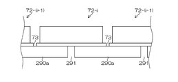
- FIGS. 15 and 16 show a more preferable embodiment of the liquid intrusion prevention pad 290a shown in FIGS. 15 is a bottom view of the head module 72-i and the liquid intrusion prevention pads 290a and 290b as seen from below, and FIG. 16 is a cross-sectional view taken along the line 16-16 in FIG.
- the liquid intrusion prevention pad 290a has an inclined end surface 293 on the upper side in the gravity direction in the width direction of the liquid droplet ejection head of the liquid intrusion prevention pad 290a.
- the rest is the same as FIG. 13 and FIG.
- the end surface 293 on the upper side in the gravity direction in the width direction of the liquid intrusion prevention pad 290a is formed to be inclined, the guiding ability to guide the ink to the flow path 291 is improved. Accordingly, it is possible to further prevent the ink overflowing from the nozzles from entering the head module gap when the droplet discharge head is pressurized and purged.
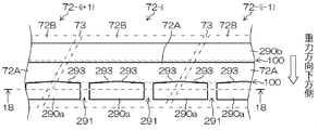
- FIG. 17 and FIG. 18 show a more preferable aspect of the liquid intrusion prevention pad 290a shown in FIG. 15 and FIG. 17 is a bottom view of the head module 72-i and the liquid intrusion prevention pads 290a and 290b as seen from below, and FIG. 18 is a cross-sectional view taken along the line 18-18 in FIG.
- the liquid intrusion prevention pad 290a shown in FIG. 17 and FIG. 18 is an aspect having two or more flow paths 291 for one head module. That is, the liquid intrusion prevention pad 290a on the lower side in the gravitational direction is a mode in which more pads than the liquid intrusion prevention pad 290a shown in FIGS. Have two or more for one head module 72-i. In other respects, it is the same as FIG. 15 and FIG.
- the liquid collecting ability is improved by having two or more flow paths 291 of the liquid intrusion prevention pad 290a for one head module 72-i. Accordingly, it is possible to further prevent the ink overflowing from the nozzles from entering the head module gap when the droplet discharge head is pressurized and purged.
- FIG. 19 and 20 show a more preferable aspect of the liquid intrusion prevention pad 290a shown in FIG. 15 and FIG. 19 is a bottom view of the head module 72-i and the liquid intrusion prevention pads 290a and 290b as viewed from below, and FIG. 20 is a cross-sectional view taken along the line 20-20 in FIG.
- the liquid intrusion prevention pad 290a shown in FIGS. 19 and 20 is manufactured as a single member by installing a pad 300 having a low height between the pads of the liquid intrusion prevention pad 290a in FIGS. . In other respects, it is the same as FIG. 15 and FIG.
- FIGS. 17 and 18 show a more preferable embodiment of the liquid intrusion prevention pad 290a shown in FIGS. 17 and 18.
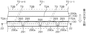
- FIG. 21 is a bottom view of the head module 72-i and the liquid intrusion prevention pads 290a and 290b as seen from below
- FIG. 22 is a cross-sectional view taken along the line 22-22 in FIG.
- the liquid intrusion prevention pad 290a shown in FIGS. 21 and 22 is produced as a single member by installing a pad 300 having a low height between the pads of the liquid intrusion prevention pad 290a in FIGS. . In other respects, it is the same as FIG. 17 and FIG.
- the liquid intrusion prevention pad 290a shown in FIGS. 17 and 18 completely forms the gap 100 between the nozzle surface 72A of the head module and the head module support member 72B by the flow path 291 as in the liquid intrusion prevention pad 290a of FIGS. I can't block it. Therefore, the ink intrusion mode that travels through the gap 100 between the nozzle surface 72A of the head module and the head module support member 72B cannot be completely prevented.
- the liquid intrusion prevention pad 290a shown in FIGS. 21 and 22 the gap 100 between the nozzle surface 72A of the head module and the head module support member 72B can be completely prevented.
- a nozzle surface cleaning device for cleaning the nozzle surfaces 72AM, 72AK, 72AC, 72AY of the inkjet heads 72M, 72K, 72C, 72Y between the image recording position and the retracted position. 260 is provided. Each of the inkjet heads 72M, 72K, 72C, 72Y is moved by the nozzle surface cleaning device 260 in the process of moving from the retracted position to the image recording position or in the process of moving from the image recording position to the retracted position. 72AC, 72AY are cleaned.
- the nozzle surface cleaning device 260 includes a cleaning liquid applying device 262 and a nozzle surface wiping device 264.
- the cleaning liquid applying device 262 applies a cleaning liquid to the nozzle surfaces 72AM, 72AK, 72AC, 72AY of the inkjet heads 72M, 72K, 72C, 72Y that move from the image recording position toward the retracted position.
- the nozzle surface wiping device 264 presses and contacts the wiping web against the nozzle surfaces 72AM, 72AK, 72AC, 72AY of the inkjet heads 72M, 72K, 72C, 72Y to which the cleaning liquid is applied, so that the nozzle surfaces 72AM, 72AK, 72AC, Wipe 72AY.
- the cleaning liquid applying device 262 and the nozzle surface wiping device 264 are arranged on the moving path of the head support frame 240. At this time, the nozzle surface wiping device 264 is disposed on the retreat position side with respect to the cleaning liquid applying device 262. Thereby, when each inkjet head 72M, 72K, 72C, 72Y is moved from the image recording position to the retracted position, the nozzle surfaces 72AM, 72AK, 72AC, 72AY can be wiped with the wiping web after the cleaning liquid is applied.
- Liquid intrusion prevention pad (lower side in the gravity direction), 290b ... Pads, 291 ... flow paths, 292a, 292b ... support members, 293 ... end faces on the upper side in the direction of gravity, 300 ... pads with low height
Landscapes
- Ink Jet (AREA)
Abstract
液滴吐出ヘッドの加圧パージをする際にノズルからあふれ出てくる液体がヘッドモジュール隙間に浸入するのを防ぐことができる画像記録装置を提供する。液体を吐出する複数のノズル151が配置されたノズル面72Aを有するヘッドモジュール72がヘッドモジュール支持部材72Bで固定されて複数繋ぎ合わされ、ノズル面72Aが水平面に対して傾斜して設けられる液滴吐出ヘッド72と、液滴吐出ヘッド72が加圧パージを行う際に、ノズル151から吐出する液体を受ける受部材280と、受部材280に設けられ、加圧パージの際に液滴吐出ヘッド72に当接し、加圧パージにより吐出した液体がヘッドモジュール間73へ侵入するのを防ぐ液体侵入防止パッド290aと、を備え、液体侵入防止パッド290aは、非吸収材料で形成され、ノズル面72Aの傾斜によって加圧パージにより吐出した液体が集められる流路291を有するようにする。
Description
本発明は、画像記録装置に係り、特に複数のヘッドモジュールを繋ぎ合わせて構成される液滴吐出ヘッドを備えた画像記録装置に関する。
一般的な画像記録装置として、搬送される記録媒体に対して、ヘッドからインクを吐出させて、画像を形成するインクジェット記録装置が知られている。
インクジェット記録装置において、画像を高精度に記録するためには、搬送される記録媒体に対してヘッドを高精度に位置決めして取り付ける必要がある。
このインクジェット記録装置の中には、画像記録の高速化を図るために、記録媒体の幅に満たないノズル列長を有する短尺なヘッド(ヘッドモジュール)を複数個繋ぎ合わせて主走査方向に延伸したヘッド構成の液滴吐出ヘッド(ラインヘッド)がある。
ところで、このように複数のヘッドモジュールを繋ぎ合わせて構成される液滴吐出ヘッドは、その構造上、ノズル面に隙間が生じてしまう。すなわち、液滴吐出ヘッドにおけるノズル面も隣り合うヘッドモジュールのノズル面同士を繋ぎ合わせて構成されるため、ヘッドモジュールの接合部分で隙間が生じてしまう。このような隙間がノズル面に存在していると、加圧パージした際に、加圧パージしたインクが隙間に入り込んでしまうという問題がある。そして、隙間にインクが入り込むと、そのインクが隙間に溜まっていき、最悪の場合、ヘッド寿命や信頼性、印字性能の低下、記録媒体の汚損を引き起こす。
特許文献1には、吸収体をノズル面の隙間に入り込むように配置することで、ノズル面の隙間に入り込んでいるインクが吸収体によって効果的に吸収されることが記載されている。
しかしながら、特許文献1において、吸収体はノズル開口を避けてノズル面の隙間に配置しているが、吸収体を微小な隙間に入れることは非常に難しく、また吸収体がインク(液体)を蓄積していくため、吸収体自体のクリーニングが必要になってしまうという問題がある。
本発明は、このような事情に鑑みてなされたもので、液滴吐出ヘッドの加圧パージをする際にノズルからあふれ出てくる液体がヘッドモジュール隙間に浸入するのを防ぐことができる画像記録装置を提供することを目的とする。
上記課題を解決するための手段は次のとおりである。
第1の態様は、液体を吐出する複数のノズルが配置されたノズル面を有するヘッドモジュールがヘッドモジュール支持部材で固定されて複数繋ぎ合わされ、ノズル面が水平面に対して傾斜して設けられる液滴吐出ヘッドと、液滴吐出ヘッドが加圧パージを行う際に、ノズルから吐出する液体を受ける受部材と、受部材に設けられ、加圧パージの際に液滴吐出ヘッドに当接し、加圧パージにより吐出した液体がヘッドモジュール間へ侵入するのを防ぐ液体侵入防止パッドと、を備え、液体侵入防止パッドは、液体を吸収しない非吸収材料で形成され、ノズル面の傾斜によって前記加圧パージにより吐出した液体が集められる流路を有する画像記録装置である。なお、ここでいう「水平面」とは、重力方向に直行する方向に延びる面をいうものである。
加圧パージによるヘッドモジュール間への液体の浸入は、2つのモードがあり、加圧パージされた液体が直接に浸入するモードと、ヘッドモジュールのノズル面とヘッドモジュール支持部材との隙間を伝っていくモードと、がある。特にノズル面が水平面に対して傾斜して設けられた液滴吐出ヘッドでは、ノズル面に付着した液体は、重力による流れによりノズル面とヘッドモジュール支持部材との隙間に入り込む。ノズル面とヘッドモジュール支持部材との隙間に入り込んだ液体は、ノズル面とヘッドモジュール支持部材との隙間を伝ってヘッドモジュール隙間(ヘッドモジュール間)に侵入しやすい。
本態様によれば、加圧パージを行う際にノズルから吐出する液体を受ける受部材に加圧パージ時に液体の浸入を防止するための液体侵入防止パッドを設ける。液体侵入防止パッドは、液体を吸収しない材料で形成されている。また、液体侵入防止パッドは、加圧パージにより吐出した液体を集める流路を有する。即ち、液体侵入防止パッドは、液体を吸収しない非吸収材料で形成され、ノズル面の傾斜によって加圧パージにより吐出した液体を集める流路を有することで、加圧パージにより吐出した液体はヘッドモジュール支持部材の任意の位置に集められるので、ヘッドモジュール間に液体が侵入するのを防ぐことができる。
したがって、本態様により、加圧パージによるヘッドモジュール間への液体の浸入を未然に防ぎ、液滴吐出ヘッドの長寿命および信頼性を保証する。なお、本態様のインク浸入防止パッドは、位置決め精度が必要ないので、非常に簡単にヘッドモジュール間を塞ぐことができる。
第2の態様は、第1の態様の画像記録装置において、液体侵入防止パッドは、ヘッドモジュール支持部材の位置に設けられた隙間であって、加圧パージにより吐出した液体が集められる流路を有し、水平面に対して傾斜して設けられたノズル面の重力方向下方側のノズル面とヘッドモジュール支持部材との隙間を非流路で塞ぐ複数のパッドである態様である。なお、ここでいう「重力方向下方側」とは、重力方向側をいうものであり、反対に「重力方向上方側」とは、重力方向に対向する方向の側をいうものである。
本態様によれば、液体侵入防止パッドは、水平面に対して傾斜して設けられたノズル面の重力方向下方側のノズル面とヘッドモジュール支持部材との隙間を、ヘッドモジュール間ではない位置に設けられた流路を除き、塞ぐ。これにより、加圧パージにより吐出した液体は任意の位置に集められるので、ヘッドモジュール間に液体が侵入するのを防ぐことができる。
第3の態様は、第1の態様の画像記録装置において、液体侵入防止パッドは、水平面に対して傾斜して設けられたノズル面の重力方向下方側のノズル面とヘッドモジュール支持部材との隙間を塞ぐ一連のパッドであり、液滴吐出ヘッドへの非当接面に加圧パージにより吐出した液体が集められる流路を有する態様である。
液体侵入防止パッドは、水平面に対して傾斜して設けられたノズル面の重力方向下方側のノズル面とヘッドモジュール支持部材との隙間を全て塞ぎ、加圧パージにより吐出した液体を集める流路を有しているので、第2の態様と比べて、ノズル面とヘッドモジュール支持部材との隙間を伝っていくモードによるヘッドモジュール間への液体の浸入を完全に防ぐことができる。
第4の態様は、第2又は第3の態様の画像記録装置において、液体侵入防止パッドは、液滴吐出ヘッドに対して重力方向上方側の端面が、流路に加圧パージにより吐出した液体を流路に誘導する傾斜に形成されている態様である。
本態様によれば、液体侵入防止パッドの重力方向上方側の端面が傾斜に形成されている。これにより、液体を流路に誘導する誘導能力が向上する。
第5の態様は、第2から第4のいずれか1つの態様の画像記録装置において、液体侵入防止パッドは、水平面に対して傾斜して設けられたノズル面の重力方向上方側のノズル面とヘッドモジュール支持部材との隙間を塞ぐ一連のパッドを更に有する態様である。
本態様によれば、水平面に対して傾斜して設けられたノズル面の重力方向下方側のノズル面とヘッドモジュール支持部材との隙間だけでなく、水平面に対して傾斜して設けられたノズル面の重力方向上方側のノズル面とヘッドモジュール支持部材との隙間も液体侵入防止パッドで塞ぐ。これにより、更にヘッドモジュール間に液体が侵入するのを防ぐことができる。
第6の態様は、第2から第5のいずれか1つの態様の画像記録装置において、流路は、1つのヘッドモジュールに対して2つ以上有する態様である。
本態様によれば、流路は1つのヘッドモジュールに対して2つ以上有する。これにより、液体の収集能力が向上する。
第7の態様は、第1から第6のいずれか1つの態様の画像記録装置において、液体侵入防止パッドは、弾性体で構成される態様である。
本態様によれば、液体侵入防止パッドは、弾性体で構成されるので、高い密閉性をもってノズル面とヘッドモジュール支持部材との隙間を閉塞することができる。また、液体侵入防止パッドがノズル面を傷付けることを防ぐこともできる。
第8の態様は、第1から第7のいずれか1つの態様の画像記録装置において、液体侵入防止パッドは、端面が親水化処理されている態様である。
本態様によれば、液体侵入防止パッドの端面が親水化処理されているので、液体の収集能力が更に向上する。
第9の態様は、第1から第8のいずれか1つの態様の画像記録装置において、液体侵入防止パッドは、支持部材を介して受部材に固定されている態様である。
第10の態様は、第1から第9のいずれか1つの態様の画像記録装置において、受部材は、ノズル面を保湿する保湿キャップを備え、加圧パージを行う際にノズルから吐出する液体は、受部材の内部で受ける態様である。
本発明によれば、液滴吐出ヘッドの加圧パージをする際にノズルからあふれ出てくる液体がヘッドモジュール隙間に浸入するのを防ぐことができる
以下、添付図面に従って本発明に係る画像記録装置の好ましい実施の形態について説明する。なお、以下では、液滴吐出ヘッドの一例として、インクジェットヘッドについて説明する。また、このインクジェットヘッドを有するインクジェット記録装置について説明する。
≪インクジェット記録装置の全体構成≫
まず、インクジェット記録装置の全体構成について説明する。図1は、インクジェット記録装置の全体構成を示した構成図である。
まず、インクジェット記録装置の全体構成について説明する。図1は、インクジェット記録装置の全体構成を示した構成図である。
このインクジェット記録装置10は、描画部16の圧胴(描画ドラム70)に保持された記録媒体24(便宜上「用紙」と呼ぶ場合がある。)にインクジェットヘッド72M、72K、72Cおよび72Yから複数色のインクを打滴して所望のカラー画像を形成する圧胴直描方式のインクジェット記録装置であり、インクの打滴前に記録媒体24上に処理液(ここでは凝集処理液)を付与し、処理液とインク液を反応させて記録媒体24上に画像形成を行なう2液反応(凝集)方式が適用されたオンデマンドタイプの画像形成装置である。
図示のように、インクジェット記録装置10は、主として、給紙部12、処理液付与部14、描画部16、乾燥部18、定着部20、および排出部22を備えて構成される。
(給紙部)
給紙部12は、記録媒体24を処理液付与部14に供給する機構であり、当該給紙部12には、枚葉紙である記録媒体24が積層されている。給紙部12には、給紙トレイ50が設けられ、この給紙トレイ50から記録媒体24が一枚ずつ処理液付与部14に給紙される。
給紙部12は、記録媒体24を処理液付与部14に供給する機構であり、当該給紙部12には、枚葉紙である記録媒体24が積層されている。給紙部12には、給紙トレイ50が設けられ、この給紙トレイ50から記録媒体24が一枚ずつ処理液付与部14に給紙される。
本例のインクジェット記録装置10では、記録媒体24として、紙種や大きさ(用紙サイズ)の異なる複数種類の記録媒体24を使用することができる。給紙部12において各種の記録媒体をそれぞれ区別して集積する複数の用紙トレイ(不図示)を備え、これら複数の用紙トレイの中から給紙トレイ50に送る用紙を自動で切り換える態様も可能であるし、必要に応じてオペレータが用紙トレイを選択し、若しくは交換する態様も可能である。なお、本例では、記録媒体24として、枚葉紙(カット紙)を用いるが、連続用紙(ロール紙)から必要なサイズに切断して給紙する構成も可能である。
(処理液付与部)
処理液付与部14は、記録媒体24の記録面に処理液を付与する機構である。処理液は、描画部16で付与されるインク中の色材(本例では顔料)を凝集させる色材凝集剤を含んでおり、この処理液とインクとが接触することによって、インクは色材と溶媒との分離が促進される。
処理液付与部14は、記録媒体24の記録面に処理液を付与する機構である。処理液は、描画部16で付与されるインク中の色材(本例では顔料)を凝集させる色材凝集剤を含んでおり、この処理液とインクとが接触することによって、インクは色材と溶媒との分離が促進される。
図1に示すように、処理液付与部14は、給紙胴52、処理液ドラム54、および処理液塗布装置56を備えている。処理液ドラム54は、記録媒体24を保持し、回転搬送させるドラムである。処理液ドラム54は、その外周面に爪形状の保持手段(グリッパー)55を備え、この保持手段55の爪と処理液ドラム54の周面の間に記録媒体24を挟み込むことによって記録媒体24の先端を保持できるようになっている。処理液ドラム54は、その外周面に吸着穴を設けるとともに、吸着穴から吸引を行なう吸引手段を接続してもよい。これにより記録媒体24を処理液ドラム54の周面に密着保持することができる。
処理液ドラム54の外側には、その周面に対向して処理液塗布装置56が設けられる。処理液塗布装置56は、処理液が貯留された処理液容器と、この処理液容器の処理液に一部が浸漬されたアニックスローラと、アニックスローラと処理液ドラム54上の記録媒体24に圧接されて計量後の処理液を記録媒体24に転移するゴムローラとで構成される。この処理液塗布装置56によれば、処理液を計量しながら記録媒体24に塗布することができる。
処理液付与部14で処理液が付与された記録媒体24は、処理液ドラム54から中間搬送部26を介して描画部16の描画ドラム70へ受け渡される。
(描画部)
描画部16は、描画ドラム(第2の搬送体)70、用紙抑えローラ74、およびインクジェットヘッド72M,72K,72C,72Yを備えている。描画ドラム70は、処理液ドラム54と同様に、その外周面に爪形状の保持手段(グリッパー)71を備える。描画ドラム70に固定された記録媒体24は、記録面が外側を向くようにして搬送され、この記録面にインクジェットヘッド72M,72K,72C,72Yからインクが付与される。
描画部16は、描画ドラム(第2の搬送体)70、用紙抑えローラ74、およびインクジェットヘッド72M,72K,72C,72Yを備えている。描画ドラム70は、処理液ドラム54と同様に、その外周面に爪形状の保持手段(グリッパー)71を備える。描画ドラム70に固定された記録媒体24は、記録面が外側を向くようにして搬送され、この記録面にインクジェットヘッド72M,72K,72C,72Yからインクが付与される。
インクジェットヘッド72M,72K,72C,72Yはそれぞれ、記録媒体24における画像形成領域の最大幅に対応する長さを有するフルライン型のインクジェット方式の記録ヘッド(インクジェットヘッド)とすることが好ましい。インク吐出面には、画像形成領域の全幅にわたってインク吐出用のノズルが複数配列されたノズル列が形成されている。各インクジェットヘッド72M,72K,72C,72Yは、記録媒体24の搬送方向(描画ドラム70の回転方向)と直交する方向に延在するように設置される。
描画ドラム70上に密着保持された記録媒体24の記録面に向かって各インクジェットヘッド72M,72K,72C,72Yから、対応する色インクの液滴が吐出されることにより、処理液付与部14で予め記録面に付与された処理液にインクが接触し、インク中に分散する色材(顔料)が凝集され、色材凝集体が形成される。これにより、記録媒体24上での色材流れなどが防止され、記録媒体24の記録面に画像が形成される。
なお、本例では、CMYKの標準色(4色)の構成を例示したが、インク色や色数の組合せについては本実施形態に限定されず、必要に応じて淡インク、濃インク、特別色インクを追加してもよい。例えば、ライトシアン、ライトマゼンタなどのライト系インクを吐出するインクジェットヘッドを追加する構成も可能であり、各色ヘッドの配置順序も特に限定はない。
描画部16で画像が形成された記録媒体24は、描画ドラム70から中間搬送部28を介して乾燥部18の乾燥ドラム76へ受け渡される。
(乾燥部)
乾燥部18は、色材凝集作用により分離された溶媒に含まれる水分を乾燥させる機構であり、図1に示すように、乾燥ドラム76、および溶媒乾燥装置78を備えている。
乾燥部18は、色材凝集作用により分離された溶媒に含まれる水分を乾燥させる機構であり、図1に示すように、乾燥ドラム76、および溶媒乾燥装置78を備えている。
乾燥ドラム76は、処理液ドラム54と同様に、その外周面に爪形状の保持手段(グリッパー)77を備え、この保持手段77によって記録媒体24の先端を保持できるようになっている。
溶媒乾燥装置78は、乾燥ドラム76の外周面に対向する位置に配置され、複数のIRヒータ82と、各IRヒータ82の間にそれぞれ配置された温風噴出しノズル80とで構成される。
各温風噴出しノズル80から記録媒体24に向けて吹き付けられる温風の温度と風量、各IRヒータ82の温度を適宜調節することにより、様々な乾燥条件を実現することができる。
また、乾燥ドラム76の表面温度は50℃以上に設定されている。記録媒体24の裏面から加熱を行なうことによって乾燥が促進され、定着時における画像破壊を防止することができる。なお、乾燥ドラム76の表面温度の上限については、特に限定されるものではないが、乾燥ドラム76の表面に付着したインクをクリーニングするなどのメンテナンス作業の安全性(高温による火傷防止)の観点から75℃以下(より好ましくは60℃以下)に設定されることが好ましい。
乾燥ドラム76の外周面に、記録媒体24の記録面が外側を向くように(即ち、記録媒体24の記録面が凸側となるように湾曲させた状態で)保持し、回転搬送しながら乾燥することで、記録媒体24のシワや浮きの発生を防止でき、これらに起因する乾燥ムラを確実に防止することができる。
乾燥部18で乾燥処理が行なわれた記録媒体24は、乾燥ドラム76から中間搬送部30を介して定着部20の定着ドラム84へ受け渡される。
(定着部)
定着部20は、定着ドラム84、ハロゲンヒータ86、定着ローラ88、およびインラインセンサ90で構成される。定着ドラム84は、処理液ドラム54と同様に、その外周面に爪形状の保持手段(グリッパー)85を備え、この保持手段85によって記録媒体24の先端を保持できるようになっている。
定着部20は、定着ドラム84、ハロゲンヒータ86、定着ローラ88、およびインラインセンサ90で構成される。定着ドラム84は、処理液ドラム54と同様に、その外周面に爪形状の保持手段(グリッパー)85を備え、この保持手段85によって記録媒体24の先端を保持できるようになっている。
定着ドラム84の回転により、記録媒体24は記録面が外側を向くようにして搬送され、この記録面に対して、ハロゲンヒータ86による予備加熱と、定着ローラ88による定着処理と、インラインセンサ90による検査が行なわれる。
ハロゲンヒータ86は、所定の温度(例えば、180℃)に制御される。これにより、記録媒体24の予備加熱が行なわれる。
定着ローラ88は、乾燥させたインクを加熱加圧することによってインク中の自己分散性熱可塑性樹脂微粒子を溶着し、インクを皮膜化させるためのローラ部材であり、記録媒体24を加熱加圧するように構成される。具体的には、定着ローラ88は、定着ドラム84に対して圧接するように配置されており、定着ドラム84との間でニップローラを構成するようになっている。これにより、記録媒体24は、定着ローラ88と定着ドラム84との間に挟まれ、所定のニップ圧(例えば、0.15MPa)でニップされ、定着処理が行なわれる。
また、定着ローラ88は、熱伝導性の良いアルミなどの金属パイプ内にハロゲンランプを組み込んだ加熱ローラによって構成され、所定の温度(たとえば60~80℃)に制御される。この加熱ローラで記録媒体24を加熱することによって、インクに含まれる熱可塑性樹脂微粒子のTg温度(ガラス転移点温度)以上の熱エネルギーが付与され、熱可塑性樹脂微粒子が溶融される。これにより、記録媒体24の凹凸に押し込み定着が行なわれるとともに、画像表面の凹凸がレベリングされ、光沢性が得られる。
なお、図1の実施形態では、定着ローラ88を1つだけ設けた構成となっているが、画像層厚みや熱可塑性樹脂微粒子のTg特性に応じて、複数段設けた構成でもよい。
一方、インラインセンサ90は、記録媒体24に定着された画像について、チェックパターンや水分量、表面温度、光沢度などを計測するための計測手段であり、CCDラインセンサなどが適用される。
上記の如く構成された定着部20によれば、乾燥部18で形成された薄層の画像層内の熱可塑性樹脂微粒子が定着ローラ88によって加熱加圧されて溶融されるので、記録媒体24に固定定着させることができる。また、定着ドラム84の表面温度を50℃以上に設定することで、定着ドラム84の外周面に保持された記録媒体24を裏面から加熱することによって乾燥が促進され、定着時における画像破壊を防止することができるとともに、画像温度の昇温効果によって画像強度を高めることができる。
また、インク中にUV硬化性モノマーを含有させた場合は、乾燥部で水分を充分に揮発させた後に、UV照射ランプを備えた定着部で、画像にUVを照射することで、UV硬化性モノマーを硬化重合させ、画像強度を向上させることができる。
(排出部)
図1に示すように、定着部20に続いて排出部22が設けられている。排出部22は、排出トレイ92を備えており、この排出トレイ92と定着部20の定着ドラム84との間に、これらに対接するように渡し胴94、搬送ベルト96および張架ローラ98が設けられている。記録媒体24は、渡し胴94により搬送ベルト96に送られ、排出トレイ92に排出される。
図1に示すように、定着部20に続いて排出部22が設けられている。排出部22は、排出トレイ92を備えており、この排出トレイ92と定着部20の定着ドラム84との間に、これらに対接するように渡し胴94、搬送ベルト96および張架ローラ98が設けられている。記録媒体24は、渡し胴94により搬送ベルト96に送られ、排出トレイ92に排出される。
また、図1には示されていないが、本例のインクジェット記録装置10には、上記構成の他、各インクジェットヘッド72M,72K,72Cおよび72Yにインクを供給するインク貯蔵/装填部、処理液付与部14に対して処理液を供給する手段を備えるとともに、各インクジェットヘッド72M,72K,72Cおよび72Yのクリーニング(ノズル面のワイピング、パージ、ノズル吸引等)を行なうヘッドメンテナンス部や、用紙搬送路上における記録媒体24の位置を検出する位置検出センサ、装置各部の温度を検出する温度センサなどを備えている。
<ヘッド>
図2は、インクジェットヘッド72の構造例を示す平面図であり、インクジェットヘッド72をノズル面72A側から見た図である。また、図3は図2の一部拡大図である。
図2は、インクジェットヘッド72の構造例を示す平面図であり、インクジェットヘッド72をノズル面72A側から見た図である。また、図3は図2の一部拡大図である。
図2に示すように、インクジェットヘッド72はn個のヘッドモジュール72-i(i=1,2,3,…,n)を長手方向(記録媒体24(図1参照)の搬送方向と直交する方向)に沿ってつなぎ合わせた構造を有し、記録媒体の全幅に対応する長さにわたって複数のノズル(図2中不図示)が設けられている。
各ヘッドモジュール72-iは、インクジェットヘッド72における短手方向の両側からヘッドモジュール支持部材72Bによって支持されている。また、インクジェットヘッド72の長手方向における両端部はヘッド支持部材72Dによって支持されている。
図3に示すように、各ヘッドモジュール72-i(n番目のヘッドモジュール72-n)は、複数のノズルがマトリクス状に配列された構造を有している。図3において符号151Aを付して図示した斜めの実線は、複数のノズルが一列に並べられたノズル列を表している。
図4(a)は、ヘッドモジュール72-iの平面透視図であり、図4(b)はその一部の拡大図である。
記録媒体24上に形成されるドットピッチを高密度化するためには、インクジェットヘッド72におけるノズルピッチを高密度化する必要がある。本例のヘッドモジュール72-iは、図4(a)、図4(b)に示すように、インク吐出口であるノズル151と、各ノズル151に対応する圧力室152等からなる複数のインク室ユニット(記録素子単位としての液滴吐出素子)153を千鳥でマトリクス状に(2次元的に)配置させた構造を有し、これにより、ヘッド長手方向(記録媒体24の搬送方向と直交する方向;主走査方向)に沿って並ぶように投影される実質的なノズル間隔(投影ノズルピッチ)の高密度化を達成している。
各ノズル151に対応して設けられている圧力室152は、その平面形状が概略正方形となっており、対角線上の両隅部の一方にノズル151が設けられ、他方に供給口154が設けられている。なお、圧力室152の形状は、本例に限定されず、平面形状が四角形(菱形、長方形など)、五角形、六角形その他の多角形、円形、楕円形など、多様な形態があり得る。
かかる構造を有するインク室ユニット153を図4(b)に示す如く、主走査方向に沿う行方向および主走査方向に対して直交しない一定の角度θを有する斜めの列方向に沿って一定の配列パターンで格子状に多数配列させることにより、本例の高密度ノズルヘッドが実現されている。
即ち、主走査方向に対してある角度θの方向に沿ってインク室ユニット153を一定のピッチdで複数配列する構造により、主走査方向に並ぶように投影されたノズルのピッチPはd×cosθとなり、主走査方向については、各ノズル151が一定のピッチPで直線状に配列されたものと等価的に取り扱うことができる。このような構成により、主走査方向に並ぶように投影されるノズル列が1インチ当たり2400個(2400ノズル/インチ)におよぶ高密度のノズル構成を実現することが可能になる。
≪メンテナンス部の説明≫
次にメンテナンス部の説明をする。図5は、インクジェット記録装置の描画部を示す側面図であり、図6は、インクジェット記録装置の描画部を示す正面図であり、図7は、インクジェット記録装置の描画部の概略構成を示す上面図である。
次にメンテナンス部の説明をする。図5は、インクジェット記録装置の描画部を示す側面図であり、図6は、インクジェット記録装置の描画部を示す正面図であり、図7は、インクジェット記録装置の描画部の概略構成を示す上面図である。
描画ドラム70は、その回転軸218の両端部を一対の軸受222に軸支されて回転自在に設けられている(図6参照)。一対の軸受222は、インクジェット記録装置の本体フレーム220に設けられており、この一対の軸受222に回転軸218の両端部が軸支されることにより、描画ドラム70は水平に取り付けられる(水平な設置面に対して回転軸218が平行に取り付けられる。)。
4本のインクジェットヘッド72M、72K、72Cおよび72Yは、描画ドラム70の回転軸218を中心とした同心円上に一定の間隔をもって放射状に配置され、図6に示すように、ヘッド支持フレーム240に取り付けられて、描画ドラム70の周囲に配置される。
ヘッド支持フレーム240は、描画ドラム70の回転軸218と直交して設けられた一対のサイドプレート242Lおよび242Rと、その一対のサイドプレート242Lおよび242Rを上端部で連結する連結フレーム244とで構成されている。
一対のサイドプレート242Lおよび242Rは、板状に形成されており、描画ドラム70を挟んで互いに対向するように配置されている。この一対のサイドプレート242L、242Rの内側には、各インクジェットヘッド72M、72K、72Cおよび72Yを取り付けるための取付部246M、246K、246Cおよび246Yが設けられている(図6では、便宜上、取付部246Yのみ図示)。
取付部246C、246M、246Yおよび246Kは、描画ドラム70の回転軸218を中心とした同心円上に一定の間隔をもって放射状に配置されている。各インクジェットヘッド72M、72K、72Cおよび72Yは、その両端に形成された被取付部248M、248K、248Cおよび248Y(図6では、便宜上、被取付部248Yのみ図示)を取付部246M、246K、246Cおよび246Yに固定することにより、ヘッド支持フレーム240に取り付けられる。そして、このヘッド支持フレーム240に取り付けられることにより、各インクジェットヘッド72M、72K、72Cおよび72Yが、描画ドラム70の回転軸218を中心とした同心円上に一定の間隔をもって放射状に配置される。
ヘッド支持フレーム240は、図示しないガイドレールにガイドされて、描画ドラム70の回転軸218と平行にスライド移動自在に設けられている。そして、図示しないリニア駆動機構(たとえば、送りネジ機構など)に駆動されて、図6に実線で示す「画像記録位置」と図6に破線で示す「退避位置(メンテナンス位置)」との間を移動する。
各インクジェットヘッド72M、72K、72Cおよび72Yは、ヘッド支持フレーム240を画像記録位置に位置させると、描画ドラム70の周囲に配置され、画像記録可能な状態になる。
退避位置は、各インクジェットヘッド72M、72K、72Cおよび72Yが描画ドラム70から退避する位置に設定される。この退避位置には、各インクジェットヘッド72M、72K、72Cおよび72Yをメンテナンスするためのメンテナンスユニット250が設けられる。
メンテナンスユニット250には、各インクジェットヘッド72M、72K、72Cおよび72Yのノズル面を覆う受部材(キャップ)280M、280K、280Cおよび280Y(図6では、便宜上、受部材280Yのみ図示)が備えられている。装置を長時間停止する場合などは、この受部材280M、280K、280Cおよび280Yでノズル面が覆われる。これにより、乾燥による不吐出が防止される。
なお、この受部材280M、280K、280Cおよび280Yには、図示しない加圧および吸引機構が備えられており、ノズル内を加圧および吸引できるように構成されている。
また、この受部材280M、280K、280Cおよび280Yには、図示しない洗浄液供給機構が備えられており、内部に洗浄液を供給できるように構成されている。
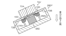
図8及び図9は、インクジェットヘッド72Yと受部材280Yを示す側面断面図である。なお、図10は、図8及び図9の受部材280Yを上面から見たものの一例である。
受部材280Yには、保湿キャップ282が備えられている。保湿キャップ282は、保湿液が供給されている(不図示)。インクジェットヘッド72Yは、退避位置で上下動するように構成されている。
保湿キャップ282は、インクジェットヘッド72Yのノズル面72Aを覆って、インクジェットヘッド72Yをキャッピングする部材である。図9に示すように、インクジェット記録装置10を長期間使用しないときには、この保湿キャップ282でインクジェットヘッド72Yのノズル面72Aが覆われる。これにより、ノズルから溶媒が蒸発するのを防止でき、また、ノズル面72Aに異物が付着するのを防止できる。なお、保湿液には、例えば、純水が用いられる。
加圧バージする場合は、インクジェットヘッド72Yのノズル面72Aを保湿キャップ282で覆った状態でヘッド内を加圧し、ノズルからインクを排出させる。これにより、パージされたインクを保湿キャップ282で回収することができる。
なお、図示しないが、保湿キャップには、保湿液を供給する保湿液供給装置と、保湿キャップ内の保湿液等を廃液する廃液装置等を備えて構成されている。
ここで、このようにインクを加圧パージする際に、ヘッドモジュール間へインクが浸入し易い。図5に示したように、4本のインクジェットヘッド72M、72K、72Cおよび72Yは、ノズル面が水平面に対して傾斜して設けられている。
加圧パージによるヘッドモジュール間へのインクの浸入は、2つのモードがあり、図11に示すように加圧パージされたインクが直接に浸入するモードと、図12に示すようにヘッドモジュールのノズル面72Aとヘッドモジュール支持部材72Bとの隙間100を伝っていくモードと、がある。特に図5に示したようにノズル面が水平面に対して傾斜して設けられたインクジェットヘッドでは、ノズル面に付着したインクは、重力による流れによりノズル面とヘッドモジュール支持部材との隙間に入り込む。ノズル面72Aとヘッドモジュール支持部材72Bとの隙間に入り込んだインクは、ノズル面72Aとヘッドモジュール支持部材72Bとの隙間を伝ってヘッドモジュール間73に侵入しやすい。なお、ここで、ノズル面が水平面に対して傾斜して設けられているとは、ノズル面が水平面に対して平行ではない状態で設けられていることをいい、1°以上89°以下水平面に対して傾斜して設けられていることをいう。
そこで、ノズル面72Aが傾斜していることによりノズル面72Aに付着したインクが重力による流れによってノズル面72Aとヘッドモジュール支持部材72Bとの隙間に入り込むのを防ぐため、図8及び図9に示すように、インクがヘッドモジュール間へ侵入するのを防ぐ液体侵入防止パッド290aおよび290bを備えるようにした。
なお、液体侵入防止パッド290aおよび290bは、ノズル面72Aのノズル151を塞がないように備えることが必要である。
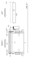
図10は、図8及び図9の受部材280Yを上面から見たものであり、液体侵入防止パッド290aおよび290bを備えたものを示す上面図である。また、図13及び図14は、ヘッドモジュール72-iと液体侵入防止パッド290aおよび290bとを示すものであり、図13は、ヘッドモジュール72-iと液体侵入防止パッド290aおよび290bとを下から見た下面図であり、図14は、図13の14-14線における断面図である。
液滴吐出ヘッド72Yは、ノズル面72Aが水平面に対して傾斜して設けられている。液滴吐出ヘッド72Yの加圧パージを行う際にインクを受ける受部材280Yは、ノズル面72Aに平行に設けられている。即ち、受部材280Yは、ノズル面72Aと同様に水平面に対して傾斜して設けられている。
ここで、受部材280Yは、受部材280Yが水平面に対して傾斜しているときに重力方向下方側に液体侵入防止パッド290aが設けられ、重力方向上方側に液体侵入防止パッド290bが設けられるように傾斜している。液体侵入防止パッド290aおよび290bは、支持部材292aおよび292bを介して受部材280Yに固定されている。図9に示したように、支持部材292aおよび292bは、液滴吐出ヘッド72Yと液体侵入防止パッド290aおよび290bとを隙間なく密着させなければいけないので、バネのような復元力を有する、一定の力で液滴吐出ヘッド72Yに液体侵入防止パッド290aおよび290bを押し当てられるような部材であることが好ましい。
図10、図13及び図14の例では、保湿キャップ282が受部材280Yに備えられており、保湿キャップ282がノズル面72Aを覆う。そして、受部材280Yを保湿キャップ282に当接させて加圧パージを行う際に、ノズル面72Aとヘッドモジュール支持部材72Bとの隙間100を塞ぐように液体侵入防止パッド290aおよび290bが受部材280Yに設けられている。
重力方向下方側の液体侵入防止パッド290aには、流路291を有している。即ち、重力方向下方側の液体侵入防止パッド290aは、複数の液体侵入防止パッドが隙間を設けて並べられている。加圧パージによりノズル面72Aに付着したインクは、この流路291によってヘッドモジュール支持部材72Bの任意の位置に集めて受部材280Yの内部に廃棄される。なお、図13及び図14に示したように、重力方向下方側の液体侵入防止パッド290aが複数のパッドが隙間を設けて並べられている態様の場合、ヘッドモジュール間73では無い位置に流路291を有するように液体侵入防止パッド290aを設ける必要がある。
重力方向上方側の液体侵入防止パッド290bは、1つのパッドによりノズル面72Aとヘッドモジュール支持部材72Bとの隙間100を塞ぐ位置に設けられている。なお、重力方向上方側の液体侵入防止パッド290bは、ノズル面72Aとヘッドモジュール支持部材72Bの重力方向上方側の隙間100を塞ぐが、ノズル面に付着したインクは重力による流れによっては重力方向上方側の隙間100にはインクが流れ込み難い。したがって、上流の液体侵入防止パッド290bは有ることが好ましいが、無くても良い。
ヘッドモジュール72-iは、液体侵入防止パッド290aおよび290bに当接するので、液体侵入防止パッド290aおよび290bは、ヘッドモジュール72-iを傷つけない柔軟性を有する材料(弾性体)であることが好ましい。また、液体侵入防止パッド290aおよび290bは、インクを吸収しない材料でなければならない。したがって、液体侵入防止パッド290aおよび290bは、例えば、シリコーンゴム、ゴム、その他の樹脂材料などが構成材料として好ましい。
このように、液体侵入防止パッドが、液体を吸収しない材料で形成され、加圧パージにより吐出したインクを集める流路を有することで、加圧パージにより吐出したインクは任意の位置に集められるので、ヘッドモジュール間にインクが侵入するのを防ぐことができる。
なお、液体侵入防止パッド290aは、端面が親水化処理されていることが好ましい。インクが触れる部分の端面を親水化処理することで、インクを引き込む効果を有するので、インクの収集能力が更に向上する。
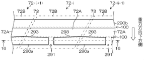
図15及び図16は、図13及び図14に示した液体侵入防止パッド290aの更に好ましい態様を示したものである。図15は、ヘッドモジュール72-iと液体侵入防止パッド290aおよび290bとを下から見た下面図であり、図16は、図15の16-16線における断面図である。
図15及び図16に示す液体侵入防止パッド290aは、液体侵入防止パッド290aの液滴吐出ヘッドの幅方向の重力方向上方側にある端面293が傾斜に形成されている。なお、その他においては、図13及び図14と同じである。
液体侵入防止パッド290aの幅方向の重力方向上方側にある端面293が傾斜に形成されていることにより、インクを流路291に誘導する誘導能力が向上する。したがって、液滴吐出ヘッドの加圧パージをする際にノズルからあふれ出てくるインクがヘッドモジュール隙間に浸入するのをより防ぐことができる。
図17及び図18は、図15及び図16に示した液体侵入防止パッド290aの更に好ましい態様を示したものである。図17は、ヘッドモジュール72-iと液体侵入防止パッド290aおよび290bとを下から見た下面図であり、図18は、図17の18-18線における断面図である。
図17及び図18に示す液体侵入防止パッド290aは、1つのヘッドモジュールに対して2つ以上の流路291を有する態様である。即ち、重力方向下方側の液体侵入防止パッド290aは、図15及び図16に示した液体侵入防止パッド290aのパッドよりも多くのパッドが隙間を設けて並べられている態様であり、流路291が1つのヘッドモジュール72-iに対して2つ以上有する。なお、その他においては、図15及び図16と同じである。
液体侵入防止パッド290aの流路291が1つのヘッドモジュール72-iに対して2つ以上有することにより、液体の収集能力が向上する。したがって、液滴吐出ヘッドの加圧パージをする際にノズルからあふれ出てくるインクがヘッドモジュール隙間に浸入するのをより防ぐことができる。
図19及び図20は、図15及び図16に示した液体侵入防止パッド290aの更に好ましい態様を示したものである。図19は、ヘッドモジュール72-iと液体侵入防止パッド290aおよび290bとを下から見た下面図であり、図20は、図19の20-20線における断面図である。
図19及び図20に示す液体侵入防止パッド290aは、図15及び図16の液体侵入防止パッド290aのパッドの間に高さの低いパッド300を設置して、一個の部材として作製したものである。なお、その他においては、図15及び図16と同じである。
図15及び図16の液体侵入防止パッド290aは、流路291によりヘッドモジュールのノズル面72Aとヘッドモジュール支持部材72Bとの隙間100を完全に塞ぐことができない。よって、ヘッドモジュールのノズル面72Aとヘッドモジュール支持部材72Bとの隙間100を伝っていくインク侵入モードを完全に防ぐことができない。図19及び図20に示した液体侵入防止パッド290aのようにすることで、ヘッドモジュールのノズル面72Aとヘッドモジュール支持部材72Bとの隙間100を完全に防ぐことができる。
図21及び図22は、図17及び図18に示した液体侵入防止パッド290aの更に好ましい態様を示したものである。図21は、ヘッドモジュール72-iと液体侵入防止パッド290aおよび290bとを下から見た下面図であり、図22は、図21の22-22線における断面図である。
図21及び図22に示す液体侵入防止パッド290aは、図17及び図18の液体侵入防止パッド290aのパッドの間に高さの低いパッド300を設置して、一個の部材として作製したものである。なお、その他においては、図17及び図18と同じである。
図17及び図18の液体侵入防止パッド290aは、図15及び図16の液体侵入防止パッド290aと同様、流路291によりヘッドモジュールのノズル面72Aとヘッドモジュール支持部材72Bとの隙間100を完全に塞ぐことができない。よって、ヘッドモジュールのノズル面72Aとヘッドモジュール支持部材72Bとの隙間100を伝っていくインク侵入モードを完全に防ぐことができない。図21及び図22に示した液体侵入防止パッド290aのようにすることで、ヘッドモジュールのノズル面72Aとヘッドモジュール支持部材72Bとの隙間100を完全に防ぐことができる。
なお、図6に示すように、画像記録位置と退避位置との間には、各インクジェットヘッド72M、72K、72C、72Yのノズル面72AM、72AK、72AC、72AYを清掃するためのノズル面清掃装置260が設けられている。各インクジェットヘッド72M、72K、72C、72Yは、退避位置から画像記録位置に移動する過程で、または、画像記録位置から退避位置に移動する過程で、このノズル面清掃装置260によってノズル面72AM、72AK、72AC、72AYが清掃される。
図6に示すように、ノズル面清掃装置260は、洗浄液付与装置262とノズル面払拭装置264とを備えて構成されている。
洗浄液付与装置262は、画像記録位置から退避位置に向かって移動する各インクジェットヘッド72M、72K、72C、72Yのノズル面72AM、72AK、72AC、72AYに洗浄液を付与する。
ノズル面払拭装置264は、洗浄液が付与された各インクジェットヘッド72M、72K、72C、72Yのノズル面72AM、72AK、72AC、72AYに払拭ウエブを押圧当接させて、ノズル面72AM、72AK、72AC、72AYを払拭する。
洗浄液付与装置262とノズル面払拭装置264は、ヘッド支持フレーム240の移動経路上に配置される。この際、ノズル面払拭装置264が洗浄液付与装置262に対して退避位置側に配置される。これにより、各インクジェットヘッド72M、72K、72C、72Yを画像記録位置から退避位置に移動させた際、洗浄液の付与後に払拭ウエブでノズル面72AM、72AK、72AC、72AYを払拭することができる。
10…インクジェット記録装置、12…給紙部、14…処理液付与部、16…描画部、18…乾燥部、20…定着部、22…排出部、24…記録媒体、70…描画ドラム、72…インクジェットヘッド(液滴吐出ヘッド)、72A…ノズル面、72B…ヘッドモジュール支持部材、73…ヘッドモジュール間、100…隙間、151…ノズル、250…メンテナンスユニット、260…ノズル面清掃装置、262…洗浄液付与装置、264…ノズル面払拭装置、280…受部材(キャップ)、282…保湿キャップ、290a…(重力方向下方側の)液体侵入防止パッド、290b…(重力方向上方側の)液体侵入防止パッド、291…流路、292a、292b…支持部材、293…重力方向上方側の端面、300…高さの低いパッド
Claims (10)
- 液体を吐出する複数のノズルが配置されたノズル面を有するヘッドモジュールがヘッドモジュール支持部材で固定されて複数繋ぎ合わされ、ノズル面が水平面に対して傾斜して設けられる液滴吐出ヘッドと、
前記液滴吐出ヘッドが加圧パージを行う際に、前記ノズルから吐出する液体を受ける受部材と、
前記受部材に設けられ、前記加圧パージの際に前記液滴吐出ヘッドに当接し、前記加圧パージにより吐出した液体がヘッドモジュール間へ侵入するのを防ぐ液体侵入防止パッドと、
を備え、
前記液体侵入防止パッドは、
前記液体を吸収しない非吸収材料で形成され、前記ノズル面の傾斜によって前記加圧パージにより吐出した液体が集められる流路を有する画像記録装置。 - 前記液体侵入防止パッドは、
前記ヘッドモジュール支持部材の位置に設けられた隙間であって、前記加圧パージにより吐出した液体が集められる流路を有し、水平面に対して傾斜して設けられたノズル面の重力方向下方側の前記ノズル面と前記ヘッドモジュール支持部材との隙間を非流路で塞ぐ複数のパッドである請求項1に記載の画像記録装置。 - 前記液体侵入防止パッドは、
水平面に対して傾斜して設けられたノズル面の重力方向下方側の前記ノズル面と前記ヘッドモジュール支持部材との隙間を塞ぐ一連のパッドであり、前記液滴吐出ヘッドへの非当接面に前記加圧パージにより吐出した液体が集められる流路を有する請求項1に記載の画像記録装置。 - 前記液体侵入防止パッドは、
前記液滴吐出ヘッドに対して重力方向上方側の端面が、前記流路に前記加圧パージにより吐出した液体を前記流路に誘導する傾斜に形成されている請求項2又は3に記載の画像記録装置。 - 前記液体侵入防止パッドは、
水平面に対して傾斜して設けられたノズル面の重力方向上方側の前記ノズル面と前記ヘッドモジュール支持部材との隙間を塞ぐ一連のパッドを更に有する請求項2から4の何れか1項に記載の画像記録装置。 - 前記流路は、1つの前記ヘッドモジュールに対して2つ以上有する請求項2から5の何れか1項に記載の画像記録装置。
- 前記液体侵入防止パッドは、弾性体で構成される請求項1から6の何れか1項に記載の画像記録装置。
- 前記液体侵入防止パッドは、端面が親水化処理されている請求項1から7の何れか1項に記載の画像記録装置。
- 前記液体侵入防止パッドは、支持部材を介して前記受部材に固定されている請求項1から8の何れか1項に記載の画像記録装置。
- 前記受部材は、前記ノズル面を保湿する保湿キャップを備え、
前記加圧パージを行う際に前記ノズルから吐出する液体は、前記受部材の内部で受ける請求項1から9の何れか1項に記載の画像記録装置。
Priority Applications (1)
| Application Number | Priority Date | Filing Date | Title |
|---|---|---|---|
| US15/079,705 US9481176B2 (en) | 2013-10-23 | 2016-03-24 | Image printing apparatus |
Applications Claiming Priority (2)
| Application Number | Priority Date | Filing Date | Title |
|---|---|---|---|
| JP2013220133A JP6157311B2 (ja) | 2013-10-23 | 2013-10-23 | 画像記録装置 |
| JP2013-220133 | 2013-10-23 |
Related Child Applications (1)
| Application Number | Title | Priority Date | Filing Date |
|---|---|---|---|
| US15/079,705 Continuation US9481176B2 (en) | 2013-10-23 | 2016-03-24 | Image printing apparatus |
Publications (1)
| Publication Number | Publication Date |
|---|---|
| WO2015060023A1 true WO2015060023A1 (ja) | 2015-04-30 |
Family
ID=52992628
Family Applications (1)
| Application Number | Title | Priority Date | Filing Date |
|---|---|---|---|
| PCT/JP2014/073476 Ceased WO2015060023A1 (ja) | 2013-10-23 | 2014-09-05 | 画像記録装置 |
Country Status (3)
| Country | Link |
|---|---|
| US (1) | US9481176B2 (ja) |
| JP (1) | JP6157311B2 (ja) |
| WO (1) | WO2015060023A1 (ja) |
Cited By (1)
| Publication number | Priority date | Publication date | Assignee | Title |
|---|---|---|---|---|
| JP7563213B2 (ja) | 2021-02-08 | 2024-10-08 | ブラザー工業株式会社 | 液体吐出装置、その制御方法及びプログラム |
Families Citing this family (8)
| Publication number | Priority date | Publication date | Assignee | Title |
|---|---|---|---|---|
| US9511584B2 (en) * | 2012-09-25 | 2016-12-06 | Hewlett-Packard Development Company, L.P. | Print head die with thermal control |
| JPWO2018230275A1 (ja) * | 2017-06-15 | 2020-03-19 | 富士フイルム株式会社 | 保湿装置、メンテナンス装置、及び液体吐出装置 |
| JP7452043B2 (ja) * | 2020-01-31 | 2024-03-19 | セイコーエプソン株式会社 | 記録装置 |
| JP7401367B2 (ja) * | 2020-03-23 | 2023-12-19 | 株式会社Screenホールディングス | 印刷装置 |
| JP7494073B2 (ja) | 2020-09-23 | 2024-06-03 | 株式会社Screenホールディングス | 印刷装置およびインク吐出用のヘッドのメンテナンス方法 |
| JP7701846B2 (ja) | 2021-09-24 | 2025-07-02 | 株式会社Screenホールディングス | 印刷装置およびインク吸引部清掃方法 |
| JP7642508B2 (ja) | 2021-09-24 | 2025-03-10 | 株式会社Screenホールディングス | クリーニングユニット、印刷装置およびロール径取得方法 |
| JP2024045922A (ja) | 2022-09-22 | 2024-04-03 | 株式会社Screenホールディングス | 印刷装置およびメンテナンス方法 |
Citations (8)
| Publication number | Priority date | Publication date | Assignee | Title |
|---|---|---|---|---|
| JPH02179761A (ja) * | 1988-12-30 | 1990-07-12 | Canon Inc | 画像記録装置 |
| JPH05330030A (ja) * | 1992-06-01 | 1993-12-14 | Canon Inc | 記録装置 |
| JPH06962A (ja) * | 1992-06-18 | 1994-01-11 | Ricoh Co Ltd | インク記録装置 |
| JP2005329551A (ja) * | 2004-05-18 | 2005-12-02 | Toshiba Tec Corp | インクジェット記録装置 |
| JP2008522859A (ja) * | 2004-12-06 | 2008-07-03 | シルバーブルック リサーチ ピーティワイ リミテッド | インクジェット印字ヘッドアセンブリ用のキャッピングシステム |
| JP2009172875A (ja) * | 2008-01-24 | 2009-08-06 | Olympus Corp | 画像記録装置 |
| JP2009274285A (ja) * | 2008-05-13 | 2009-11-26 | Fuji Xerox Co Ltd | 液滴吐出装置 |
| JP2011183730A (ja) * | 2010-03-10 | 2011-09-22 | Ricoh Co Ltd | 画像形成装置 |
Family Cites Families (9)
| Publication number | Priority date | Publication date | Assignee | Title |
|---|---|---|---|---|
| JP3187607B2 (ja) * | 1993-05-25 | 2001-07-11 | キヤノン株式会社 | インクジェット記録装置 |
| JP3467716B2 (ja) * | 1995-05-25 | 2003-11-17 | セイコーエプソン株式会社 | インクジェット記録ヘッド用キャッピング装置 |
| JP3704820B2 (ja) * | 1996-07-16 | 2005-10-12 | ブラザー工業株式会社 | インクジェットヘッドのキャップ手段 |
| JP2003159787A (ja) * | 2001-11-28 | 2003-06-03 | Seiko Epson Corp | 吐出方法およびその装置、電気光学装置、その製造方法およびその製造装置、カラーフィルタ、その製造方法およびその製造装置、ならびに基材を有するデバイス、その製造方法およびその製造装置 |
| JP2005074767A (ja) * | 2003-08-29 | 2005-03-24 | Matsushita Electric Ind Co Ltd | インクジェット式記録装置 |
| JP2008221836A (ja) * | 2007-02-13 | 2008-09-25 | Brother Ind Ltd | 吐出ヘッドのキャップ装置および回復装置 |
| JP2009196291A (ja) * | 2008-02-25 | 2009-09-03 | Seiko Epson Corp | 流体吐出装置におけるノズル検査装置、流体吐出装置及びノズル検査方法 |
| JP2013049246A (ja) * | 2011-08-31 | 2013-03-14 | Fujifilm Corp | インクジェットヘッド、インクジェットヘッド洗浄システム、および、インクジェットヘッドの洗浄方法 |
| JP2013173264A (ja) * | 2012-02-24 | 2013-09-05 | Fujifilm Corp | 液滴吐出ヘッドの払拭装置 |
-
2013
- 2013-10-23 JP JP2013220133A patent/JP6157311B2/ja not_active Expired - Fee Related
-
2014
- 2014-09-05 WO PCT/JP2014/073476 patent/WO2015060023A1/ja not_active Ceased
-
2016
- 2016-03-24 US US15/079,705 patent/US9481176B2/en not_active Expired - Fee Related
Patent Citations (8)
| Publication number | Priority date | Publication date | Assignee | Title |
|---|---|---|---|---|
| JPH02179761A (ja) * | 1988-12-30 | 1990-07-12 | Canon Inc | 画像記録装置 |
| JPH05330030A (ja) * | 1992-06-01 | 1993-12-14 | Canon Inc | 記録装置 |
| JPH06962A (ja) * | 1992-06-18 | 1994-01-11 | Ricoh Co Ltd | インク記録装置 |
| JP2005329551A (ja) * | 2004-05-18 | 2005-12-02 | Toshiba Tec Corp | インクジェット記録装置 |
| JP2008522859A (ja) * | 2004-12-06 | 2008-07-03 | シルバーブルック リサーチ ピーティワイ リミテッド | インクジェット印字ヘッドアセンブリ用のキャッピングシステム |
| JP2009172875A (ja) * | 2008-01-24 | 2009-08-06 | Olympus Corp | 画像記録装置 |
| JP2009274285A (ja) * | 2008-05-13 | 2009-11-26 | Fuji Xerox Co Ltd | 液滴吐出装置 |
| JP2011183730A (ja) * | 2010-03-10 | 2011-09-22 | Ricoh Co Ltd | 画像形成装置 |
Cited By (1)
| Publication number | Priority date | Publication date | Assignee | Title |
|---|---|---|---|---|
| JP7563213B2 (ja) | 2021-02-08 | 2024-10-08 | ブラザー工業株式会社 | 液体吐出装置、その制御方法及びプログラム |
Also Published As
| Publication number | Publication date |
|---|---|
| US9481176B2 (en) | 2016-11-01 |
| US20160200106A1 (en) | 2016-07-14 |
| JP2015080913A (ja) | 2015-04-27 |
| JP6157311B2 (ja) | 2017-07-05 |
Similar Documents
| Publication | Publication Date | Title |
|---|---|---|
| JP6157311B2 (ja) | 画像記録装置 | |
| US8282188B2 (en) | Inkjet head cleaning apparatus, image recording apparatus and inkjet head cleaning method | |
| JP5356463B2 (ja) | ノズル面洗浄装置および液滴吐出装置 | |
| JP5177868B2 (ja) | インクジェット記録装置及び打滴検出方法 | |
| US8109599B2 (en) | Liquid ejection apparatus and method of inspecting cleaning apparatus of liquid ejection apparatus | |
| JP5952669B2 (ja) | 液体吐出装置、及び液体吐出ヘッドの保湿装置 | |
| US20090251522A1 (en) | Target transport device and recording apparatus | |
| JP5597485B2 (ja) | 洗浄装置及び塗布装置並びに画像形成装置 | |
| US10035345B2 (en) | Inkjet recording apparatus and control method therefor | |
| JP2013173264A (ja) | 液滴吐出ヘッドの払拭装置 | |
| JP2013049246A (ja) | インクジェットヘッド、インクジェットヘッド洗浄システム、および、インクジェットヘッドの洗浄方法 | |
| JP5798092B2 (ja) | 液体吐出装置、及び液体吐出ヘッドの保湿装置 | |
| US8960849B2 (en) | Method for analyzing positional deviation of head modules, recording medium, and method for adjusting inkjet head | |
| US7134750B2 (en) | Ink jet printer | |
| CN103538377B (zh) | 涂布装置及喷墨记录装置 | |
| JP6114885B2 (ja) | 払拭部材、ノズル払拭ユニット、及び画像形成装置 | |
| JP6112990B2 (ja) | 液体吐出ヘッドのメンテナンス方法、液体吐出ヘッド | |
| JP5885300B2 (ja) | 液滴吐出ヘッドおよびノズル面のメンテナンスシステム | |
| JP2010194893A (ja) | ヘッド洗浄装置及び画像記録装置並びにヘッド洗浄方法 | |
| JP5911779B2 (ja) | 画像記録装置及びその制御方法 | |
| JP5832407B2 (ja) | 液体吐出ヘッドの製造方法 | |
| JP2013169651A (ja) | インクジェットヘッド洗浄システムおよびインクジェットヘッドのメンテナンス方法 | |
| JP5893575B2 (ja) | 液体吐出ヘッド、画像形成装置および液体吐出ヘッドの製造方法 | |
| JP4816784B2 (ja) | インクジェット記録装置用ベルト搬送機構 | |
| JP2013014009A (ja) | 塗布装置および画像形成装置 |
Legal Events
| Date | Code | Title | Description |
|---|---|---|---|
| 121 | Ep: the epo has been informed by wipo that ep was designated in this application |
Ref document number: 14855727 Country of ref document: EP Kind code of ref document: A1 |
|
| NENP | Non-entry into the national phase |
Ref country code: DE |
|
| 122 | Ep: pct application non-entry in european phase |
Ref document number: 14855727 Country of ref document: EP Kind code of ref document: A1 |