WO2015037709A1 - 金属板、金属板の製造方法、および金属板を用いてマスクを製造する方法 - Google Patents
金属板、金属板の製造方法、および金属板を用いてマスクを製造する方法 Download PDFInfo
- Publication number
- WO2015037709A1 WO2015037709A1 PCT/JP2014/074255 JP2014074255W WO2015037709A1 WO 2015037709 A1 WO2015037709 A1 WO 2015037709A1 JP 2014074255 W JP2014074255 W JP 2014074255W WO 2015037709 A1 WO2015037709 A1 WO 2015037709A1
- Authority
- WO
- WIPO (PCT)
- Prior art keywords
- metal plate
- steepness
- vapor deposition
- mask
- long metal
- Prior art date
- Legal status (The legal status is an assumption and is not a legal conclusion. Google has not performed a legal analysis and makes no representation as to the accuracy of the status listed.)
- Ceased
Links
Images










Classifications
-
- C—CHEMISTRY; METALLURGY
- C23—COATING METALLIC MATERIAL; COATING MATERIAL WITH METALLIC MATERIAL; CHEMICAL SURFACE TREATMENT; DIFFUSION TREATMENT OF METALLIC MATERIAL; COATING BY VACUUM EVAPORATION, BY SPUTTERING, BY ION IMPLANTATION OR BY CHEMICAL VAPOUR DEPOSITION, IN GENERAL; INHIBITING CORROSION OF METALLIC MATERIAL OR INCRUSTATION IN GENERAL
- C23F—NON-MECHANICAL REMOVAL OF METALLIC MATERIAL FROM SURFACE; INHIBITING CORROSION OF METALLIC MATERIAL OR INCRUSTATION IN GENERAL; MULTI-STEP PROCESSES FOR SURFACE TREATMENT OF METALLIC MATERIAL INVOLVING AT LEAST ONE PROCESS PROVIDED FOR IN CLASS C23 AND AT LEAST ONE PROCESS COVERED BY SUBCLASS C21D OR C22F OR CLASS C25
- C23F1/00—Etching metallic material by chemical means
-
- B—PERFORMING OPERATIONS; TRANSPORTING
- B21—MECHANICAL METAL-WORKING WITHOUT ESSENTIALLY REMOVING MATERIAL; PUNCHING METAL
- B21B—ROLLING OF METAL
- B21B1/00—Metal-rolling methods or mills for making semi-finished products of solid or profiled cross-section; Sequence of operations in milling trains; Layout of rolling-mill plant, e.g. grouping of stands; Succession of passes or of sectional pass alternations
- B21B1/22—Metal-rolling methods or mills for making semi-finished products of solid or profiled cross-section; Sequence of operations in milling trains; Layout of rolling-mill plant, e.g. grouping of stands; Succession of passes or of sectional pass alternations for rolling plates, strips, bands or sheets of indefinite length
- B21B1/227—Surface roughening or texturing
-
- B—PERFORMING OPERATIONS; TRANSPORTING
- B21—MECHANICAL METAL-WORKING WITHOUT ESSENTIALLY REMOVING MATERIAL; PUNCHING METAL
- B21B—ROLLING OF METAL
- B21B1/00—Metal-rolling methods or mills for making semi-finished products of solid or profiled cross-section; Sequence of operations in milling trains; Layout of rolling-mill plant, e.g. grouping of stands; Succession of passes or of sectional pass alternations
- B21B1/38—Metal-rolling methods or mills for making semi-finished products of solid or profiled cross-section; Sequence of operations in milling trains; Layout of rolling-mill plant, e.g. grouping of stands; Succession of passes or of sectional pass alternations for rolling sheets of limited length, e.g. folded sheets, superimposed sheets, pack rolling
-
- B—PERFORMING OPERATIONS; TRANSPORTING
- B21—MECHANICAL METAL-WORKING WITHOUT ESSENTIALLY REMOVING MATERIAL; PUNCHING METAL
- B21B—ROLLING OF METAL
- B21B15/00—Arrangements for performing additional metal-working operations specially combined with or arranged in, or specially adapted for use in connection with, metal-rolling mills
- B21B15/0007—Cutting or shearing the product
-
- C—CHEMISTRY; METALLURGY
- C23—COATING METALLIC MATERIAL; COATING MATERIAL WITH METALLIC MATERIAL; CHEMICAL SURFACE TREATMENT; DIFFUSION TREATMENT OF METALLIC MATERIAL; COATING BY VACUUM EVAPORATION, BY SPUTTERING, BY ION IMPLANTATION OR BY CHEMICAL VAPOUR DEPOSITION, IN GENERAL; INHIBITING CORROSION OF METALLIC MATERIAL OR INCRUSTATION IN GENERAL
- C23C—COATING METALLIC MATERIAL; COATING MATERIAL WITH METALLIC MATERIAL; SURFACE TREATMENT OF METALLIC MATERIAL BY DIFFUSION INTO THE SURFACE, BY CHEMICAL CONVERSION OR SUBSTITUTION; COATING BY VACUUM EVAPORATION, BY SPUTTERING, BY ION IMPLANTATION OR BY CHEMICAL VAPOUR DEPOSITION, IN GENERAL
- C23C14/00—Coating by vacuum evaporation, by sputtering or by ion implantation of the coating forming material
- C23C14/02—Pretreatment of the material to be coated
- C23C14/021—Cleaning or etching treatments
-
- C—CHEMISTRY; METALLURGY
- C23—COATING METALLIC MATERIAL; COATING MATERIAL WITH METALLIC MATERIAL; CHEMICAL SURFACE TREATMENT; DIFFUSION TREATMENT OF METALLIC MATERIAL; COATING BY VACUUM EVAPORATION, BY SPUTTERING, BY ION IMPLANTATION OR BY CHEMICAL VAPOUR DEPOSITION, IN GENERAL; INHIBITING CORROSION OF METALLIC MATERIAL OR INCRUSTATION IN GENERAL
- C23C—COATING METALLIC MATERIAL; COATING MATERIAL WITH METALLIC MATERIAL; SURFACE TREATMENT OF METALLIC MATERIAL BY DIFFUSION INTO THE SURFACE, BY CHEMICAL CONVERSION OR SUBSTITUTION; COATING BY VACUUM EVAPORATION, BY SPUTTERING, BY ION IMPLANTATION OR BY CHEMICAL VAPOUR DEPOSITION, IN GENERAL
- C23C14/00—Coating by vacuum evaporation, by sputtering or by ion implantation of the coating forming material
- C23C14/04—Coating on selected surface areas, e.g. using masks
- C23C14/042—Coating on selected surface areas, e.g. using masks using masks
-
- C—CHEMISTRY; METALLURGY
- C23—COATING METALLIC MATERIAL; COATING MATERIAL WITH METALLIC MATERIAL; CHEMICAL SURFACE TREATMENT; DIFFUSION TREATMENT OF METALLIC MATERIAL; COATING BY VACUUM EVAPORATION, BY SPUTTERING, BY ION IMPLANTATION OR BY CHEMICAL VAPOUR DEPOSITION, IN GENERAL; INHIBITING CORROSION OF METALLIC MATERIAL OR INCRUSTATION IN GENERAL
- C23C—COATING METALLIC MATERIAL; COATING MATERIAL WITH METALLIC MATERIAL; SURFACE TREATMENT OF METALLIC MATERIAL BY DIFFUSION INTO THE SURFACE, BY CHEMICAL CONVERSION OR SUBSTITUTION; COATING BY VACUUM EVAPORATION, BY SPUTTERING, BY ION IMPLANTATION OR BY CHEMICAL VAPOUR DEPOSITION, IN GENERAL
- C23C14/00—Coating by vacuum evaporation, by sputtering or by ion implantation of the coating forming material
- C23C14/06—Coating by vacuum evaporation, by sputtering or by ion implantation of the coating forming material characterised by the coating material
- C23C14/12—Organic material
-
- C—CHEMISTRY; METALLURGY
- C23—COATING METALLIC MATERIAL; COATING MATERIAL WITH METALLIC MATERIAL; CHEMICAL SURFACE TREATMENT; DIFFUSION TREATMENT OF METALLIC MATERIAL; COATING BY VACUUM EVAPORATION, BY SPUTTERING, BY ION IMPLANTATION OR BY CHEMICAL VAPOUR DEPOSITION, IN GENERAL; INHIBITING CORROSION OF METALLIC MATERIAL OR INCRUSTATION IN GENERAL
- C23C—COATING METALLIC MATERIAL; COATING MATERIAL WITH METALLIC MATERIAL; SURFACE TREATMENT OF METALLIC MATERIAL BY DIFFUSION INTO THE SURFACE, BY CHEMICAL CONVERSION OR SUBSTITUTION; COATING BY VACUUM EVAPORATION, BY SPUTTERING, BY ION IMPLANTATION OR BY CHEMICAL VAPOUR DEPOSITION, IN GENERAL
- C23C14/00—Coating by vacuum evaporation, by sputtering or by ion implantation of the coating forming material
- C23C14/22—Coating by vacuum evaporation, by sputtering or by ion implantation of the coating forming material characterised by the process of coating
- C23C14/24—Vacuum evaporation
-
- C—CHEMISTRY; METALLURGY
- C23—COATING METALLIC MATERIAL; COATING MATERIAL WITH METALLIC MATERIAL; CHEMICAL SURFACE TREATMENT; DIFFUSION TREATMENT OF METALLIC MATERIAL; COATING BY VACUUM EVAPORATION, BY SPUTTERING, BY ION IMPLANTATION OR BY CHEMICAL VAPOUR DEPOSITION, IN GENERAL; INHIBITING CORROSION OF METALLIC MATERIAL OR INCRUSTATION IN GENERAL
- C23F—NON-MECHANICAL REMOVAL OF METALLIC MATERIAL FROM SURFACE; INHIBITING CORROSION OF METALLIC MATERIAL OR INCRUSTATION IN GENERAL; MULTI-STEP PROCESSES FOR SURFACE TREATMENT OF METALLIC MATERIAL INVOLVING AT LEAST ONE PROCESS PROVIDED FOR IN CLASS C23 AND AT LEAST ONE PROCESS COVERED BY SUBCLASS C21D OR C22F OR CLASS C25
- C23F1/00—Etching metallic material by chemical means
- C23F1/02—Local etching
-
- G—PHYSICS
- G03—PHOTOGRAPHY; CINEMATOGRAPHY; ANALOGOUS TECHNIQUES USING WAVES OTHER THAN OPTICAL WAVES; ELECTROGRAPHY; HOLOGRAPHY
- G03F—PHOTOMECHANICAL PRODUCTION OF TEXTURED OR PATTERNED SURFACES, e.g. FOR PRINTING, FOR PROCESSING OF SEMICONDUCTOR DEVICES; MATERIALS THEREFOR; ORIGINALS THEREFOR; APPARATUS SPECIALLY ADAPTED THEREFOR
- G03F7/00—Photomechanical, e.g. photolithographic, production of textured or patterned surfaces, e.g. printing surfaces; Materials therefor, e.g. comprising photoresists; Apparatus specially adapted therefor
- G03F7/004—Photosensitive materials
-
- G—PHYSICS
- G03—PHOTOGRAPHY; CINEMATOGRAPHY; ANALOGOUS TECHNIQUES USING WAVES OTHER THAN OPTICAL WAVES; ELECTROGRAPHY; HOLOGRAPHY
- G03F—PHOTOMECHANICAL PRODUCTION OF TEXTURED OR PATTERNED SURFACES, e.g. FOR PRINTING, FOR PROCESSING OF SEMICONDUCTOR DEVICES; MATERIALS THEREFOR; ORIGINALS THEREFOR; APPARATUS SPECIALLY ADAPTED THEREFOR
- G03F7/00—Photomechanical, e.g. photolithographic, production of textured or patterned surfaces, e.g. printing surfaces; Materials therefor, e.g. comprising photoresists; Apparatus specially adapted therefor
- G03F7/20—Exposure; Apparatus therefor
-
- H—ELECTRICITY
- H10—SEMICONDUCTOR DEVICES; ELECTRIC SOLID-STATE DEVICES NOT OTHERWISE PROVIDED FOR
- H10K—ORGANIC ELECTRIC SOLID-STATE DEVICES
- H10K50/00—Organic light-emitting devices
- H10K50/10—OLEDs or polymer light-emitting diodes [PLED]
-
- H—ELECTRICITY
- H10—SEMICONDUCTOR DEVICES; ELECTRIC SOLID-STATE DEVICES NOT OTHERWISE PROVIDED FOR
- H10K—ORGANIC ELECTRIC SOLID-STATE DEVICES
- H10K71/00—Manufacture or treatment specially adapted for the organic devices covered by this subclass
- H10K71/10—Deposition of organic active material
- H10K71/16—Deposition of organic active material using physical vapour deposition [PVD], e.g. vacuum deposition or sputtering
- H10K71/166—Deposition of organic active material using physical vapour deposition [PVD], e.g. vacuum deposition or sputtering using selective deposition, e.g. using a mask
Definitions
- the present invention relates to a metal plate used for manufacturing a mask by forming a plurality of through holes.
- the present invention also relates to a method for manufacturing a metal plate.
- the present invention also relates to a method of manufacturing a mask having a plurality of through holes using a metal plate.
- display devices used in portable devices such as smartphones and tablet PCs are required to have high definition, for example, a pixel density of 300 ppi or more.
- the pixel density of the display device is required to be, for example, 450 ppi or more.
- Organic EL display devices are attracting attention because of their good responsiveness and low power consumption.
- a method of forming pixels of an organic EL display device a method of forming pixels with a desired pattern using a vapor deposition mask including through holes arranged in a desired pattern is known. Specifically, first, a vapor deposition mask is brought into close contact with the substrate for the organic EL display device, and then, the vapor deposition mask and the substrate that are brought into close contact with each other are put into the vapor deposition device to perform vapor deposition of an organic material or the like.
- a vapor deposition mask can be manufactured by forming a through-hole in a metal plate by etching using a photolithography technique (for example, Patent Document 1).
- a resist film is first formed on a metal plate, and then a resist pattern is formed by exposing the resist film with an exposure mask in close contact with the resist film, and then covered with the resist pattern on the metal plate.
- a through hole is formed by etching the unexposed region.
- the vapor deposition material adheres not only to the substrate but also to the vapor deposition mask.
- some vapor deposition materials are directed to the substrate along a direction that is largely inclined with respect to the normal direction of the vapor deposition mask, but such vapor deposition material is vapor deposited before reaching the substrate. It reaches the wall surface of the through hole of the mask and adheres. In this case, the vapor deposition material is less likely to adhere to the region of the substrate located near the wall surface of the through hole of the vapor deposition mask. As a result, the thickness of the deposited vapor deposition material may be smaller than other portions.
- the thickness of the metal plate used for manufacturing the vapor deposition mask is a value calculated by (base material thickness ⁇ metal plate thickness) / (base material thickness).
- the degree of non-uniform deformation due to rolling generally increases as the rolling rate increases.
- the elongation rate of the metal plate differs depending on the position in the width direction (direction orthogonal to the conveyance direction of the base material), and as a result, a corrugated shape appears on the metal plate.
- ear stretch corrugated shape at the end in the width direction
- middle stretch corrugated shape at the center in the width direction
- steepness is known as an index representing the degree of the above-described corrugated shape generated in the plate material.
- the steepness is a percentage of the height of the corrugated shape with respect to the period of the corrugated shape of the plate material.
- Japanese Patent Application Laid-Open No. 7-227620 proposes that the steepness of a rolled material be 1% or less in order to suppress warpage when half-etching is performed.
- steepness is adopted as an index representing the flatness of a plate material, and when the steepness exceeds 1.5%, the leveler threading plate is passed within an elongation of 1.0%. It has been proposed to apply.
- 2003-286527 proposes selecting copper or a copper alloy having a sufficiently flat shape as a lead frame material based on an index of steepness of 0.5%.
- these documents do not disclose the idea of evaluating the steepness at each position in the width direction of the plate. For this reason, it is thought that the conveyance failure which arises during conveyance of a board
- plate material cannot fully be suppressed by the approach regarding the steepness proposed in these literatures.
- These documents do not relate to a mask such as a vapor deposition mask, nor to an invar material generally used as a material constituting the vapor deposition mask.
- the present invention has been made in consideration of such problems, and an object of the present invention is to provide a metal plate that can be stably conveyed, which is a metal plate used for manufacturing a mask such as a vapor deposition mask. To do. Moreover, an object of this invention is to provide the manufacturing method of a metal plate, and the manufacturing method of a mask.
- the present invention is a method of manufacturing a metal plate used for manufacturing a mask by forming a plurality of through holes, The through hole of the mask is formed by etching the elongated metal plate being conveyed,
- the method of manufacturing the metal plate is as follows: A rolling step of rolling the base material to obtain the metal plate; A cutting step of cutting off one end and the other end in the width direction of the metal plate over a predetermined range, The metal plate after the cutting step has at least partially a corrugated shape resulting from the fact that the length in the longitudinal direction differs depending on the position in the width direction,
- steepness When the percentage of the height of the corrugated shape with respect to the period in the longitudinal direction of the corrugated shape of the metal plate after the cutting step is referred to as steepness, the following conditions (1) to (3) are satisfied: , (1) The maximum value of the steepness in the central portion in the width direction of the metal plate after the cutting step is 0.4% or less; (2) The maximum value of the steepness in the central portion is equal to or less than
- the mask manufactured from the metal plate may be a vapor deposition mask used for vapor deposition in a desired pattern.
- the one end side range and the other end side range of the metal plate to be cut in the cutting step are implemented before the cutting step, the corrugated shape of the metal plate. It may be determined based on the result of the observation step.
- the metal plate manufacturing method according to the present invention may further include an annealing step of annealing the metal plate obtained by the rolling step to remove internal stress of the metal plate.
- the annealing step may be performed while pulling the rolled base material in the longitudinal direction.
- the base material may be composed of an Invar material.
- the present invention is a metal plate used for manufacturing a mask by forming a plurality of through holes,
- the through hole of the mask is formed by etching the elongated metal plate being conveyed,
- the metal plate has at least partially a corrugated shape resulting from the fact that the length in the longitudinal direction differs depending on the position in the width direction;
- steepness the percentage of the height of the corrugated shape with respect to the period in the longitudinal direction of the corrugated shape of the metal plate is referred to as steepness
- the following conditions (1) to (3) are satisfied: (1) The maximum value of the steepness in the central portion in the width direction of the metal plate is 0.4% or less; (2) The maximum value of the steepness in the central portion is equal to or less than the maximum value of the steepness in one end portion in the width direction of the metal plate, and the steepness in the other end portion in the width direction of the metal plate.
- the difference between the maximum value of the steepness at the one end side portion and the maximum value of the steepness at the other end side portion is 0.4% or less;
- the one end side portion, the central portion, and the other end side portion are metal plates that occupy 30%, 40%, and 30% of the width of the metal plate, respectively.
- the mask manufactured from the metal plate according to the present invention may be a vapor deposition mask used for vapor deposition in a desired pattern.
- the metal plate according to the present invention may be made of Invar material.
- the present invention is a method of manufacturing a mask having a plurality of through holes, Preparing a metal plate having at least partially a corrugated shape resulting from a difference in length in the longitudinal direction depending on the position in the width direction; A resist pattern forming step of forming a resist pattern on the metal plate; Etching a region of the metal plate that is not covered by the resist pattern, and forming a recess in the metal plate that defines the through hole, and
- steepness When the percentage of the height of the corrugated shape with respect to the period in the longitudinal direction of the corrugated shape of the metal plate is referred to as steepness, the following conditions (1) to (3) are satisfied: (1) The maximum value of the steepness in the central portion in the width direction of the metal plate is 0.4% or less; (2) The maximum value of the steepness in the central portion is equal to or less than the maximum value of the steepness in one end portion in the width direction of the metal plate, and the steepness in the other end portion in the width direction of the metal plate.
- the difference between the maximum value of the steepness at the one end side portion and the maximum value of the steepness at the other end side portion is 0.4% or less;
- the one end side portion, the central portion, and the other end side portion occupy 30%, 40%, and 30% of the width of the metal plate, respectively.
- the mask may be a vapor deposition mask used for vapor deposition in a desired pattern.
- the said vapor deposition mask may be provided with the effective area
- the etching step etches a region of the metal plate that is not covered with the resist pattern so as to define the through hole in a region of the metal plate that forms the effective region. The concave part which becomes may be formed.
- the resist pattern forming step includes: Forming a resist film on the metal plate, vacuum-adhering an exposure mask to the resist film, and exposing the resist film in a predetermined pattern through the exposure mask. Also good.
- the metal plate may be made of an invar material.
- metal plates that can be stably conveyed in the mask manufacturing process can be selected.
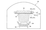
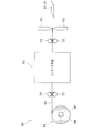
- FIG. 1 is a schematic plan view illustrating an example of a vapor deposition mask apparatus including a vapor deposition mask, for explaining an embodiment of the present invention.
- FIG. 2 is a view for explaining a method of vapor deposition using the vapor deposition mask apparatus shown in FIG.
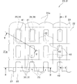
- FIG. 3 is a partial plan view showing the vapor deposition mask shown in FIG. 4 is a cross-sectional view taken along line IV-IV in FIG.
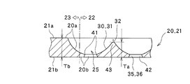
- FIG. 5 is a sectional view taken along line VV in FIG. 6 is a cross-sectional view taken along line VI-VI in FIG.
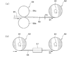
- FIG.7 (a) is a figure which shows the process of rolling a base material and obtaining the metal plate which has desired thickness
- FIG.7 (b) is the process of annealing the metal plate obtained by rolling.
- FIG. FIG. 8 is a perspective view showing a metal plate obtained by the steps shown in FIGS.
- FIGS. 9A, 9B, 9C, and 9D are cross-sectional views taken along lines aa, bb, cc, and dd in FIG. 8, respectively.
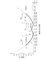
- FIG. 10 is a diagram showing the steepness at each position in the width direction of the metal plate.
- FIG. 11 is a schematic diagram for entirely explaining an example of the manufacturing method of the vapor deposition mask shown in FIG. FIG.
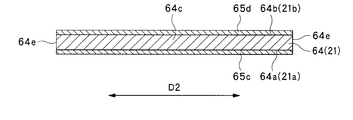
- FIG. 12 is a diagram for explaining an example of a method for manufacturing a vapor deposition mask, and is a cross-sectional view showing a step of forming a resist film on a metal plate.
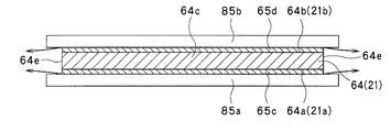
- FIG. 13 is a diagram for explaining an example of a method for manufacturing a vapor deposition mask, and is a cross-sectional view showing a step of closely attaching an exposure mask to a resist film.
- FIG. 14 is a view for explaining an example of a method of manufacturing a vapor deposition mask, and is a view showing a long metal plate in a cross section along the normal direction.
- FIG. 15 is a view for explaining an example of a method for manufacturing a vapor deposition mask, and is a view showing a long metal plate in a cross section along a normal direction.
- FIG. 16 is a view for explaining an example of a method for manufacturing a vapor deposition mask, and is a view showing a long metal plate in a cross section along the normal direction.
- FIG. 17 is a view for explaining an example of a method for manufacturing a vapor deposition mask, and is a view showing a long metal plate in a cross section along a normal direction.
- FIG. 18 is a view for explaining an example of a method of manufacturing a vapor deposition mask, and is a view showing a long metal plate in a cross section along the normal direction.
- FIG. 19 is a view for explaining an example of a method for manufacturing a vapor deposition mask, and is a view showing a long metal plate in a cross section along the normal direction.
- FIG. 20 is a diagram for explaining an example of a method for manufacturing a vapor deposition mask, and is a diagram illustrating a long metal plate in a cross section along a normal direction.
- FIG. 21 is a plan view showing a first sample placed on a surface plate.
- FIG. 22 is a plan view showing a long metal plate of a first form obtained from the first winding body.
- FIG. 23 is a plan view showing a long metal plate of a second form obtained from the first winding body.
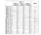
- FIG. 24 is a view showing measurement results of steepness in the first to twentieth samples cut out from the first to twentieth winding bodies.
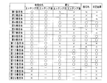
- FIG. 25 is a view showing an evaluation result of the conveyance performance in the long metal plate of the first form obtained from the first to twentieth winding bodies.
- FIG. 26 is a view showing an evaluation result of the conveyance performance in the long metal plate of the second form obtained from the first to twentieth rolls.
- FIGS. 1 to 20 are diagrams for explaining an embodiment according to the present invention.
- a method for manufacturing a vapor deposition mask used for patterning an organic material on a substrate in a desired pattern when manufacturing an organic EL display device will be described as an example.
- the present invention can be applied to a method of manufacturing a vapor deposition mask used for various purposes without being limited to such application.
- a plate is a concept that includes a member that can be called a sheet or a film. Therefore, for example, a “metal plate” is distinguished from a member called “a metal sheet” or “a metal film” only by a difference in the name. Can't be done.
- plate surface (sheet surface, film surface)
- sheet surface means a target plate-like member (sheet-like) when the target plate-like (sheet-like, film-like) member is viewed as a whole and globally. It refers to the surface that coincides with the plane direction of the member or film-like member.
- the normal direction used with respect to a plate-like (sheet-like, film-like) member refers to the normal direction with respect to the plate
- the shape, geometric conditions and physical characteristics and their degree are specified, for example, terms such as “parallel”, “orthogonal”, “identical”, “equivalent”, lengths and angles
- values of physical characteristics and the like are not limited to a strict meaning and are interpreted to include a range where a similar function can be expected.
- FIG. 1 is a plan view showing an example of a vapor deposition mask device including a vapor deposition mask
- FIG. 2 is a diagram for explaining a method of using the vapor deposition mask device shown in FIG.
- FIG. 3 is a plan view showing the vapor deposition mask from the first surface side
- FIGS. 4 to 6 are cross-sectional views at respective positions in FIG.
- the vapor deposition mask device 10 shown in FIGS. 1 and 2 includes a plurality of vapor deposition masks 20 made of a substantially rectangular metal plate 21 and a frame 15 attached to the peripheral edge of the plurality of vapor deposition masks 20. Yes. Each vapor deposition mask 20 is provided with a large number of through holes 25 formed by etching a metal plate 21 having a first surface 21a and a second surface 21b facing each other from at least the first surface 21a. As shown in FIG. 2, the vapor deposition mask device 10 is supported in the vapor deposition device 90 so that the vapor deposition mask 20 faces the lower surface of a substrate, for example, a glass substrate 92, as a vapor deposition target, and vapor deposition material for the substrate. Used for vapor deposition.
- the vapor deposition mask 20 and the glass substrate 92 come into close contact with each other by a magnetic force from a magnet (not shown).
- a crucible 94 for accommodating a vapor deposition material (for example, an organic light emitting material) 98 and a heater 96 for heating the crucible 94 are disposed below the vapor deposition mask apparatus 10.
- the vapor deposition material 98 in the crucible 94 is vaporized or sublimated by heating from the heater 96 and adheres to the surface of the glass substrate 92.
- the vapor deposition material 98 adheres to the glass substrate 92 through the through holes 25.
- the vapor deposition material 98 is formed on the surface of the glass substrate 92 in a desired pattern corresponding to the position of the through hole 25 of the vapor deposition mask 20.
- the through holes 25 are arranged in a predetermined pattern in each effective region 22.
- the vapor deposition mask 20 vapor deposition mask device 10
- the glass substrate 92 are moved relative to each other along the arrangement direction of the through holes 25 (one direction described above), and the red color is displayed.
- An organic light emitting material, a green organic light emitting material, and a blue organic light emitting material may be deposited in this order.
- the frame 15 of the vapor deposition mask device 10 is attached to the peripheral edge of the rectangular vapor deposition mask 20.
- the frame 15 holds the deposition mask in a stretched state so that the deposition mask 20 is not bent.
- the vapor deposition mask 20 and the frame 15 are fixed to each other, for example, by spot welding.
- the vapor deposition process is performed inside a vapor deposition apparatus 90 that is in a high temperature atmosphere. Therefore, during the vapor deposition process, the vapor deposition mask 20, the frame 15 and the substrate 92 held inside the vapor deposition apparatus 90 are also heated. At this time, the vapor deposition mask, the frame 15 and the substrate 92 exhibit dimensional change behavior based on their respective thermal expansion coefficients. In this case, if the thermal expansion coefficients of the vapor deposition mask 20 and the frame 15 and the substrate 92 are greatly different, a positional shift caused by a difference in their dimensional change occurs. As a result, the dimension of the vapor deposition material adhering to the substrate 92 is generated. Accuracy and position accuracy will be reduced.
- the thermal expansion coefficients of the vapor deposition mask 20 and the frame 15 are equal to the thermal expansion coefficient of the substrate 92.
- an invar material that is an iron alloy in which a predetermined amount of nickel is added to iron, for example, 36% by mass of nickel, is used as the material of the vapor deposition mask 20 and the frame 15. it can.
- the vapor deposition mask 20 is made of a metal plate 21 and has a substantially rectangular shape in a plan view, more precisely a substantially rectangular shape in a plan view.
- the metal plate 21 of the vapor deposition mask 20 includes an effective area 22 in which the through holes 25 are formed in a regular arrangement, and a surrounding area 23 surrounding the effective area 22.
- the surrounding area 23 is an area for supporting the effective area 22 and is not an area through which a deposition material intended to be deposited on the substrate passes.
- the effective region 22 is a region on the substrate (glass substrate 92) where the organic light emitting material is deposited to form a pixel. That is, it is a region in the vapor deposition mask 20 that faces an area on the substrate that forms the display surface of the produced substrate for an organic EL display device.
- through holes and recesses may be formed in the peripheral region 23 for various purposes.
- each effective region 22 has a substantially rectangular shape in plan view, more precisely, a substantially rectangular shape in plan view.
- the plurality of effective regions 22 of the vapor deposition mask 20 are arranged in a line at a predetermined interval along one direction parallel to the longitudinal direction of the vapor deposition mask 20.
- one effective area 22 corresponds to one organic EL display device. That is, according to the vapor deposition mask apparatus 10 (deposition mask 20) shown in FIG. 1, vapor deposition with multiple surfaces is possible.
- the plurality of through holes 25 formed in each effective region 22 are arranged at a predetermined pitch along two directions orthogonal to each other in the effective region 22. Yes.
- An example of the through hole 25 formed in the metal plate 21 will be described in more detail with reference mainly to FIGS.
- the plurality of through holes 25 are provided on the first surface 20 a on one side along the normal direction of the vapor deposition mask 20 and on the other side along the normal direction of the vapor deposition mask 20.
- the vapor deposition mask 20 is penetrated by extending between the second surface 20b as a side.
- a first recess 30 is formed in the metal plate 21 by etching from the side of the first surface 21a of the metal plate 21 which is one side in the normal direction of the vapor deposition mask,
- a second recess 35 is formed in the metal plate 21 from the second surface 21b side which is the other side in the normal direction of the metal plate 21, and the through hole 25 is formed by the first recess 30 and the second recess 35.
- each first recess 30 in the cross section along the line gradually decreases.
- the wall surface 31 of the first recess 30 extends in a direction intersecting with the normal direction of the vapor deposition mask 20 in the entire region, and one wall surface along the normal direction of the vapor deposition mask 20. It is exposed to the side.
- each second recess 35 in the cross section along the plate surface of the vapor deposition mask 20 at each position along the normal direction of the vapor deposition mask 20 is the second cross-sectional area from the second surface 20b side of the vapor deposition mask 20. It may be gradually reduced toward the first surface 20a.
- the wall surface 36 of the second recess 35 extends in a direction intersecting the normal direction of the vapor deposition mask 20 in the entire region, and is exposed toward the other side along the normal direction of the vapor deposition mask 20. Yes.
- the wall surface 31 of the first recess 30 and the wall surface 36 of the second recess 35 are connected via a circumferential connecting portion 41.
- the connecting portion 41 is an overhanging portion where the wall surface 31 of the first recess 30 inclined with respect to the normal direction of the vapor deposition mask and the wall surface 36 of the second recess 35 inclined with respect to the normal direction of the vapor deposition mask merge. It is defined by the ridgeline.
- the connection part 41 defines the penetration part 42 in which the area of the through-hole 25 becomes the smallest in the planar view of the vapor deposition mask 20.
- two adjacent through holes 25 are formed on the vapor deposition mask. They are separated from each other along the plate surface. That is, when the metal plate 21 is etched from the side of the second surface 21b of the metal plate 21 that corresponds to the second surface 20b of the vapor deposition mask 20, as in the manufacturing method described later, the second recess 35 is produced. The second surface 21b of the metal plate 21 remains between two adjacent second recesses 35.
- two adjacent first recesses 30 are connected on one side along the normal direction of the vapor deposition mask, that is, on the first surface 20a side of the vapor deposition mask 20. ing. That is, when the metal plate 21 is etched from the side of the first surface 21a of the metal plate 21 corresponding to the first surface 20a of the vapor deposition mask 20 to form the first recess 30 as in the manufacturing method described later. The first surface 21 a of the metal plate 21 does not remain between the two adjacent first recesses 30. That is, the first surface 21 a of the metal plate 21 is etched over the entire effective area 22.
- the vapor deposition mask 20 is formed so that the first surface 20a of the vapor deposition mask 20 faces the vapor deposition material 98 as shown in FIG.
- the utilization efficiency of the vapor deposition material 98 can be improved effectively.
- the first surface 20a of the vapor deposition mask 20 holds the vapor deposition material 98 as shown by the two-dot chain line in FIG.
- the second surface 20 b of the vapor deposition mask 20 faces the glass substrate 92. Therefore, the vapor deposition material 98 adheres to the glass substrate 92 through the first recess 30 whose cross-sectional area is gradually reduced. As indicated by arrows in FIG. 4, the vapor deposition material 98 not only moves from the crucible 94 toward the glass substrate 92 along the normal direction of the glass substrate 92, but also greatly increases with respect to the normal direction of the glass substrate 92. It may move in an inclined direction.
- the connection portion 41 that is a portion having the minimum cross-sectional area of the through hole 25 and other arbitrary positions of the wall surface 31 of the first recess 30 It is advantageous to sufficiently increase the minimum angle ⁇ 1 (see FIG. 4) formed by the straight line L1 passing through the normal direction of the vapor deposition mask 20.
- the thickness of the vapor deposition mask 20 As one method for increasing the angle ⁇ 1, it is conceivable to reduce the thickness of the vapor deposition mask 20 and thereby reduce the height of the wall surface 31 of the first recess 30 and the wall surface 36 of the second recess 35. . That is, it can be said that it is preferable to use the metal plate 21 with the smallest possible thickness within the range in which the strength of the vapor deposition mask 20 can be secured as the metal plate 21 for constituting the vapor deposition mask 20.
- the wall surfaces 31 of the two adjacent first recesses 30 are merged to compare with a recess having a wall surface (contour) indicated by a dotted line that does not merge with other recesses.
- the angle ⁇ 1 can be greatly increased (see FIG. 4). The reason will be described below.
- the first recess 30 is formed by etching the first surface 21a of the metal plate 21, as will be described in detail later.
- the wall surface of the recess formed by etching is generally a curved surface that is convex toward the erosion direction. Therefore, the wall surface 31 of the recess formed by the etching is cut off in the region which is the etching start side, and in the region opposite to the etching start side, that is, in the deepest side of the recess, the method of the metal plate 21 is performed.
- the inclination is relatively large with respect to the line direction.
- the wall surfaces 31 of the two adjacent first recesses 30 merge on the etching start side, so that the leading edges 32 of the wall surfaces 31 of the two first recesses 30 merge.
- the outer contour of the portion 43 is not a sharp shape but a chamfered shape.
- the wall surface 31 of the 1st recessed part 30 which makes most through-holes 25 can be effectively inclined with respect to the normal line direction of a vapor deposition mask. That is, the angle ⁇ 1 can be increased. Thereby, vapor deposition with a desired pattern can be stably performed with high accuracy while effectively improving the utilization efficiency of the vapor deposition material 98.
- the sheet metal plate 21 constituting the vapor deposition mask 20 is obtained from a long metal plate (hereinafter also referred to as a long metal plate) produced by rolling a base material, as will be described later. . Therefore, in order to obtain the metal plate 21 with a small thickness, it is necessary to increase the rolling rate when the base metal is rolled to produce a long metal plate. However, the greater the rolling rate, the greater the degree of non-uniform deformation due to rolling. For example, the elongation rate of the long metal plate differs depending on the position in the width direction (direction orthogonal to the conveyance direction of the base material), and as a result, the above-described corrugated shape may appear in the long metal plate.
- An etching process for forming a through hole in a long metal plate is generally performed on a long metal plate conveyed by roll-to-roll. For this reason, in order to implement an etching process efficiently, it is preferable that the conveyance property of a long metal plate is excellent.
- the conveyance property of a long metal plate is excellent.
- the thickness of the long metal plate decreases, it becomes difficult to convey the long metal plate.
- the seat refraction is particularly likely to occur starting from a roller for changing the conveying direction of the long metal plate.
- the above-mentioned corrugated shape is generated in the long metal plate, it is considered that the deviation and the seat bending are more likely to occur.
- the pressure exerted on the long metal plate by the roller for changing the conveying direction of the long metal plate is not uniform in the width direction. In a portion where no pressure is applied, the long metal plate itself floats from the roller, and further, not only floats but also breaks easily.
- the pressure exerted on the long metal plate by the pair of transport rollers that sandwich and convey the long metal plate is likely to be non-uniform in the width direction. Is considered.
- the present embodiment having such a configuration and the operation and effect thereof will be described.
- the manufacturing method of the metal plate used in order to manufacture a vapor deposition mask is demonstrated first.
- a method for manufacturing a vapor deposition mask using the obtained metal plate will be described.
- substrate using the obtained vapor deposition mask is demonstrated.
- FIG. Fig.7 (a) is a figure which shows the process of rolling a base material and obtaining the metal plate which has desired thickness
- FIG.7 (b) is the process of annealing the metal plate obtained by rolling.
- a base material 55 composed of an invar material is prepared, and this base material 55 is indicated by an arrow D1 toward a rolling device 56 including a pair of rolling rolls 56a and 56b. Transport along the transport direction.
- the base material 55 that has reached between the pair of rolling rolls 56a and 56b is rolled by the pair of rolling rolls 56a and 56b.
- the base material 55 is reduced in thickness and stretched along the conveying direction. It is.
- a long metal plate 64 having a thickness t 0 can be obtained.
- the wound body 62 may be formed by winding a long metal plate 64 around a core 61. Specific values of thickness t 0 is not particularly limited but, for example, are within the range of 0.020 ⁇ 0.100 mm.
- FIG. 7A is only an outline of the rolling process, and the specific configuration and procedure for performing the rolling process are not particularly limited.
- the rolling process includes a hot rolling process in which the base material is processed at a temperature higher than the recrystallization temperature of the invar material constituting the base material 55 and a cold rolling process in which the base material is processed at a temperature lower than the recrystallization temperature of the invar material. May be.
- a slitting step of cutting off both ends in the width direction of the long metal plate 64 obtained by the rolling step over a range of 3 to 5 mm may be performed.
- This slit process is performed in order to remove cracks that may occur at both ends of the long metal plate 64 due to rolling.
- the long metal plate 64 is annealed using an annealing device 57 as shown in FIG.
- the annealing step may be performed while pulling the long metal plate 64 in the transport direction (longitudinal direction) as shown in FIG. That is, the annealing step may be performed as continuous annealing while being conveyed, not so-called batch-type annealing.
- the period during which the annealing process is performed is appropriately set according to the thickness of the long metal plate 64, the rolling rate, and the like.
- the annealing process is performed at 500 ° C. for 60 seconds.
- the “60 seconds” means that the time required for the long metal plate 64 to pass through the space heated to 500 ° C. in the annealing device 57 is 60 seconds.
- the thickness t 0 is usually equal to the maximum thickness Tb in the peripheral region 23 of the vapor deposition mask 20.
- the rolling step described above by repeating several times the slit step and the annealing step may be manufactured of metal plate 64 elongated in the thickness t 0.
- FIG. 7B shows an example in which the annealing process is performed while pulling the long metal plate 64 in the longitudinal direction.
- the annealing process is not limited to this, and the annealing process is performed in the long metal plate 64. May be carried out with the core 61 being wound up. That is, batch-type annealing may be performed.
- the annealing process is performed in a state where the long metal plate 64 is wound around the core 61, the long metal plate 64 may be warped with warping according to the winding diameter of the wound body 62. . Therefore, depending on the winding diameter of the wound body 62 and the material constituting the base material 55, it is advantageous to perform the annealing step while pulling the long metal plate 64 in the longitudinal direction.
- both ends of the long metal plate 64 in the width direction are cut off over a predetermined range, thereby performing a cutting step of adjusting the width of the long metal plate 64 to a desired width. In this way, a long metal plate 64 having a desired thickness and width can be obtained.
- FIG. 8 is a perspective view showing the long metal plate 64 obtained by the steps shown in FIGS.
- the long metal plate 64 at least partially has a corrugated shape resulting from the fact that the length in the longitudinal direction D1 varies depending on the position in the width direction D2.
- the longitudinal direction D1 is a direction parallel to the conveying direction when the base material 55 is rolled
- the width direction D2 is a direction orthogonal to the longitudinal direction D1.
- the end of the long metal plate 64 in the width direction D2 is represented by reference numeral 64e.
- FIGS. 9A, 9B, 9C, and 9D are cross-sectional views taken along lines aa, bb, cc, and dd in FIG. 8, respectively.
- the aa line in FIG. 8 is a line extending in the longitudinal direction along the central portion 64c in the width direction of the long metal plate 64. Accordingly, FIG. 9A shows the center in the width direction of the long metal plate 64.
- the cross section of the elongate metal plate 64 in the part 64c is shown. 8 is a line extending in the longitudinal direction along the end 64e in the width direction of the long metal plate 64. Accordingly, FIG. 9D shows the width direction of the long metal plate 64 in the width direction.
- the cross section of the elongate metal plate 64 in the edge part 64e is shown.
- middle elongation appears, and therefore, the degree of the corrugated shape appearing in the long metal plate 64 in the central portion 64c in the width direction is a position slightly away from the central portion 64c. For example, it is larger than the undulating shape appearing on the long metal plate 64 at the position of the line bb in FIG.
- the long metal plate 64 according to the present embodiment also has ear extension, and therefore, the degree of the corrugated shape appearing on the long metal plate 64 at the end 64e in the width direction is slightly apart from the end 64e. It is larger than the degree of the corrugated shape appearing on the long metal plate 64 at the position, for example, the position of the cc line in FIG.
- the steepness at each position in the width direction of the long metal plate 64 is calculated.
- the “steepness” is a percentage (%) of the height H of the corrugated shape with respect to the period L in the longitudinal direction of the corrugated shape of the long metal plate 64, that is, H / L ⁇ 100 (%).
- “Period” is the distance between valleys and valleys in the corrugated shape of the long metal plate 64, and “Height” connects the valleys and valleys from the peak of the corrugated mountain. It is the distance to a straight line.
- the periods of two undulating peaks that exist along the line aa in FIG. 8 are indicated by the symbols L a1 and La2 , respectively, and the heights are indicated by the symbols H a, respectively. Indicated by a1 and H a2 .
- the steepness of the na peaks is H ana / L ana ⁇ 100 (%). Further, the steepness at the position along the aa line in FIG. 8 is the average value of the steepness of na peaks, that is, the average value of H ana / L ana ⁇ 100 (%) (na is a positive integer). Is calculated as
- the steepness at the positions along the bb line, the cc line, and the dd line in FIG. 8 is H bnb / L bnb ⁇
- the method for calculating the period and height of the corrugated shape of the long metal plate 64 is not particularly limited.
- a distance measuring device capable of measuring the distance between the two is scanned on the long metal plate 64 along the longitudinal direction D1 of the long metal plate 64 at the central portion 64c in the width direction D2, and thereby the long metal
- the height position of the surface of the plate 64 is measured at predetermined intervals along the longitudinal direction D1. This interval is, for example, in the range of 1 mm to 5 mm.
- the three-dimensional profile of the long metal plate 64 at the central portion 64c can be acquired.
- the period L ana and height H ana of each mountain can be calculated.
- FIG. 10 is a graph showing the steepness calculated at each position in the width direction D2 of the long metal plate 64.
- the horizontal axis indicates the position of the long metal plate 64 in the width direction D2
- the vertical axis indicates the steepness.
- a curve 80 that smoothly connects the steepness values calculated at the respective positions in the width direction D2 of the long metal plate 64 is shown.
- the position in the width direction D2 with the central portion 64c in the width direction D2 as the origin is indicated in the order of mm.
- the ratio of the position in the width direction D2 to the entire width of the long metal plate 64 is indicated by%.
- FIG. 10 the case where what has the full width of 500 mm is used as the elongate metal plate 64 for manufacturing the vapor deposition mask 20 is demonstrated. Therefore, for example, the ratio at the position +100 mm away from the central portion 64c in the width direction D2 is + 20%.
- the steepness of the long metal plate 64 at the positions of the aa, bb, cc, and dd lines in FIG. 8 is indicated by symbols A, B, C, and D, respectively. It is shown.
- the long metal plate 64 is selected based on the value of the steepness.
- the selection of the long metal plate 64 is performed in which only the long metal plate 64 that satisfies all of the following conditions (1) to (3) is used in the manufacturing process of the vapor deposition mask 20 described later.
- the maximum value K1 max of the steepness in the central portion R1 of the long metal plate 64 in the width direction D2 is 0.4% or less;
- the maximum value K1 max of the steepness in the central portion R1 in the width direction D2 of the long metal plate 64 is equal to or less than the maximum value K2 max in the one end portion R2 in the width direction of the long metal plate 64, and Be equal to or less than a maximum value K3 max in the other end portion R3 in the width direction of the long metal plate 64; and (3)
- the difference between the maximum value K2 max of the steepness in the one end portion R2 and the maximum value K3 max of the steepness in the other end portion R3 is 0.4% or less;
- the central portion of the long metal plate 64 is indicated by reference numeral R1
- the one end side portion located at one end side in the width direction of the long metal plate 64 relative to the central portion R1 is indicated by reference numeral R2.
- the other end portion located on the other end side in the width direction of the long metal plate 64 with respect to the center portion R1 is represented by reference numeral R3.
- the one end side portion R2, the central portion R1 and the other end side portion R3 are defined as portions that occupy 30%, 40% and 30% of the width of the long metal plate 64 after the cutting step, respectively.
- the maximum value of the steepness appears in the vicinity of the central portion 64c in the width direction of the long metal plate 64 as shown in FIG. A). Further, a local minimum value of the steepness appears at a position slightly away from the central portion in the width direction of the long metal plate 64 toward one end side or the other end side (point B). Further, the steepness increases from the point B toward one end or the other end in the width direction (point C), and the value of the steepness becomes the maximum at one end or the other end in the width direction (point D).
- the above-described condition (1) indicates that the steepness curve 80 is located below the reference line 81. It means being satisfied. In the example shown in FIG. 10, the above-mentioned condition (1) is satisfied.
- the maximum value K1 max of the steepness in the central portion R1 is equal to or less than the maximum value K2 max of the steepness in the one end portion R2, and the maximum value K3 of the steepness in the other end portion R3. It is determined whether it is below max . In the example shown in FIG. 10, the above-mentioned condition (2) is satisfied.
- condition (3) it is determined whether or not the difference between the maximum value K2 max of the steepness in the one end portion R2 and the maximum value K3 max of the steepness in the other end portion R3 is 0.4% or less. To do. In the example shown in FIG. 10, the above-mentioned condition (3) is satisfied.
- the degree of the corrugated shape is It can be determined in advance whether or not this is a problem in the subsequent manufacturing process of the vapor deposition mask 20. Thereby, the production efficiency and yield of the vapor deposition mask 20 produced from the long metal plate 64 can be improved.
- the method for obtaining the long metal plate 64 having the steepness curve 80 as shown in FIG. 10 and having a total width of 500 mm is not particularly limited.
- a long metal plate having a total width exceeding 500 mm for example, a total width of 700 mm
- both ends in the width direction of the long metal plate are cut over a predetermined range.
- a long metal plate 64 having a width of 500 mm is produced.
- an observation step of observing the corrugated shape of a long metal plate having a full width of 700 mm is performed.
- This observation step may be performed by visual observation by the operator or may be performed using the above-described distance measuring device.
- one end side of the long metal plate having a full width of 700 mm is connected to the other end.
- You may implement a cutting process so that it may cut off in a wide area compared with the side. For example, it is conceivable to cut off 150 mm on one end side and cut 50 mm on the other end side.
- the portion having such a small steepness is cut.
- the long metal plate 64 having a more ideal steepness profile can be obtained by determining the portion of the long metal plate to be cut off in the cutting step based on the result of the observation step.
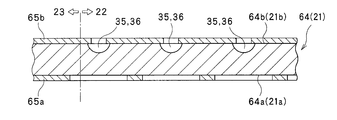
- the manufacturing method of the vapor deposition mask 20 the step of supplying a long metal plate 64 extending in a strip shape, and etching using a photolithography technique are performed on the long metal plate 64, and the long metal plate A step of forming the first recess 30 in the first surface 64a from the side of the first surface 64a and etching using a photolithography technique are performed on the long metal plate 64, and the long metal plate 64 is subjected to the second step from the second surface 64b side. Forming the two recesses 35. And the 1st recessed part 30 and the 2nd recessed part 35 which were formed in the elongate metal plate 64 mutually communicate, and the through-hole 25 is produced in the elongate metal plate 64.
- the formation process of the second recess 35 is performed before the formation process of the first recess 30, and between the formation process of the second recess 35 and the formation process of the first recess 30.
- a step of sealing the produced second recess 35 is further provided. Details of each step will be described below.
- FIG. 11 shows a manufacturing apparatus 60 for producing the vapor deposition mask 20.
- a wound body 62 in which a long metal plate 64 is wound around a core 61 is prepared.
- a long metal plate 64 extending in a strip shape is supplied as shown in FIG.
- the long metal plate 64 is formed with the through-hole 25 to form the sheet metal plate 21 and the vapor deposition mask 20.
- etching apparatus etching means
- transport roller 72 transport roller 72.
- etching means 70 etching means
- a negative photosensitive resist material is applied on the first surface 64a of the long metal plate 64 (on the lower surface of the paper surface of FIG. 12) and on the second surface 64b, Resist films 65 c and 65 d are formed on the long metal plate 64.
- exposure masks 85a and 85b are prepared so as not to transmit light to regions to be removed of the resist films 65c and 65d.
- the exposure masks 85a and 85b are respectively formed on the resist films 65c and 65d as shown in FIG. To place.
- As the exposure masks 85a and 85b for example, glass dry plates are used in which light is not transmitted to regions to be removed of the resist films 65c and 65d.
- the exposure masks 85a and 85b are sufficiently adhered to the resist films 65c and 65d by vacuum adhesion.
- a positive type may be used as the photosensitive resist material.
- an exposure mask in which light is transmitted through a region to be removed of the resist film is used as the exposure mask.
- a resist pattern (simply referred to as a resist) 65 a is formed on the first surface 64 a of the long metal plate 64, and the second surface 64 b of the long metal plate 64 is formed.
- a resist pattern (also simply referred to as a resist) 65b can be formed.
- the second surface of the long metal plate 64 using an etching solution for example, ferric chloride solution. Etching is performed from the 64b side. For example, the etching solution is sprayed toward the second surface 64b of the long metal plate 64 from the nozzle disposed on the side facing the second surface 64b of the long metal plate 64 to be conveyed through the resist pattern 65b.
- etching solution for example, ferric chloride solution.
- erosion by the etching solution proceeds in a region of the long metal plate 64 that is not covered with the resist pattern 65b.
- many second recesses 35 are formed in the long metal plate 64 from the second surface 64b side.
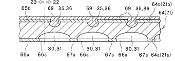
- the formed second recess 35 is covered with a resin 69 having resistance to the etching solution. That is, the second recess 35 is sealed with the resin 69 having resistance to the etching solution.
- a film of resin 69 is formed so as to cover not only the formed second recess 35 but also the second surface 64b (resist pattern 65b).
- the second etching is performed on the long metal plate 64.
- the long metal plate 64 is etched only from the first surface 64a side, and the formation of the first recess 30 proceeds from the first surface 64a side. This is because the resin 69 having resistance to the etching solution is coated on the second surface 64b side of the long metal plate 64. Therefore, the shape of the second recess 35 formed in a desired shape is not impaired by the first etching.
- Etching erosion is performed in the portion of the long metal plate 64 that is in contact with the etching solution. Therefore, erosion does not proceed only in the normal direction (thickness direction) of the long metal plate 64 but also proceeds in the direction along the plate surface of the long metal plate 64. As a result, as shown in FIG. 18, the etching proceeds in the normal direction of the long metal plate 64 so that the first recess 30 is connected to the second recess 35, and two adjacent holes 66a of the resist pattern 65a are connected. The two first recesses 30 formed at positions facing each other merge at the back side of the bridge portion 67a located between the two holes 66a.
- the etching from the first surface 64a side of the long metal plate 64 further proceeds.
- the joining portion 43 formed by joining two adjacent first concave portions 30 is separated from the resist pattern 65a, and the erosion caused by etching is caused by the metal plate in the joining portion 43 below the resist pattern 65a.
- the process proceeds in the 64 normal direction (thickness direction).
- the merging portion 43 sharpened toward one side along the normal direction of the vapor deposition mask is etched from one side along the normal direction of the vapor deposition mask, and as shown in FIG. Is done. Thereby, inclination-angle (theta) 1 which the wall surface 31 of the 1st recessed part 30 makes with respect to the normal line direction of a vapor deposition mask can be increased.
- the erosion of the first surface 64a of the long metal plate 64 by etching proceeds in the entire region that forms the effective region 22 of the long metal plate 64.
- the maximum thickness Ta along the normal direction of the long metal plate 64 in the region that forms the effective region 22 becomes thinner than the maximum thickness Tb of the long metal plate 64 before etching.
- the etching from the first surface 64a side of the long metal plate 64 proceeds by a preset amount, and the second etching for the long metal plate 64 is completed.
- the 1st recessed part 30 is extended to the position which reaches the 2nd recessed part 35 along the thickness direction of the elongate metal plate 64, and, thereby, the 1st recessed part 30 and the 2nd recessed part 35 which are mutually connected.
- Through holes 25 are formed in the long metal plate 64.
- the resin 69 is removed from the long metal plate 64 as shown in FIG.
- the resin film 69 can be removed by using, for example, an alkaline stripping solution.
- an alkaline stripping solution is used, the resist patterns 65a and 65b are removed simultaneously with the resin 69, as shown in FIG.
- the resist patterns 65a and 65b may be removed separately from the resin 69.
- the long metal plate 64 in which a large number of through holes 25 are formed in this way is conveyed to a cutting device (cutting means) 73 by conveyance rollers 72 and 72 that rotate while the long metal plate 64 is sandwiched. Is done.
- the supply core 61 described above is rotated through tension (tensile stress) acting on the long metal plate 64 by the rotation of the transport rollers 72 and 72, and the long metal plate 64 is supplied from the wound body 62. It is like that.
- the long metal plate 64 in which a large number of concave portions 30 and 35 are formed is cut into a predetermined length and width by a cutting device (cutting means) 73, thereby forming a sheet-like shape in which a large number of through holes 25 are formed.
- a metal plate 21 is obtained.
- the vapor deposition mask 20 made of the metal plate 21 having a large number of through holes 25 is obtained.
- the first surface 21 a of the metal plate 21 is etched over the entire effective region 22.
- the outer contour of the portion 43 where the tip edge 32 of the wall surface 31 of the two first recesses 30 formed on the first surface 21a side is reduced, and the thickness of the effective region 22 of the vapor deposition mask 20 is reduced, It can be a chamfered shape. Therefore, the above-described angle ⁇ 1 can be increased, thereby improving the utilization efficiency of the vapor deposition material and the positional accuracy of the vapor deposition.
- the thickness of the long metal plate 64 prepared for producing the vapor deposition mask 20 is small, for example, about 0.020 to 0.100 mm.
- the long metal plate 64 conveyed by roll-to-roll in the manufacturing process of the vapor deposition mask 20 is originally thin and further thinned locally after the etching process. Therefore, after the etching process, the seat refraction is more likely to occur.
- this buckling is likely to occur when a large middle elongation occurs in the long metal plate 64.
- Various things can be considered about the correlation between the medium elongation and the buckling.
- the fact that a large amount of medium elongation occurs means that a portion where tensile stress for conveyance is not sufficiently applied (hereinafter also referred to as a bumpy portion) is present in the central portion R1 in the width direction of the long metal plate 64. It means that it becomes easy to do. If such a bumpy portion exists, the tensile stress applied to the long metal plate 64 becomes non-uniform around the bumpy portion, so that deformation along the conveyance direction is likely to occur.
- a long metal whose maximum value K1 max of the steepness in the central portion R1 of the long metal plate 64 in the width direction D2 is 0.4% or less is satisfied according to the condition (1).
- a plate 64 is used. That is, the degree of bumping at the central portion R1 is small. For this reason, it is possible to suppress the occurrence of deformation such as seat refraction. For this reason, the vapor deposition mask 20 can be manufactured with a high yield.
- the transport direction of the long metal plate 64 is an ideal transport direction, that is, a transport roller. A so-called deviation that is shifted from a direction orthogonal to the axial direction of 72 is likely to occur.
- the tensile stress applied to the one end portion R2 of the long metal plate 64 is extremely larger than the tensile stress applied to the central portion R1 and the other end portion R3 of the long metal plate 64, the long metal plate The conveyance direction of 64 is shifted to one end side of the long metal plate 64.
- the long metal plate 64 may move out of the conveyance region and become unable to be conveyed. Therefore, the tendency to be shifted means not only that the quality of the obtained vapor deposition mask 20 is lowered, but also that the production efficiency and yield of the vapor deposition mask 20 are lowered.
- the position of the object to be conveyed is monitored in the width direction, and based on the monitoring result, the conveyance direction is to prevent the object conveyance direction from deviating greatly from the ideal.
- the control means for performing the correction is normally provided.
- the object may come off the conveyance roller before the correction of the conveyance direction is completed. Therefore, it is important that the tensile stress applied to the object is not locally increased without relying solely on the control means.
- the maximum value K1 max of the steepness in the central portion R1 in the width direction D2 of the long metal plate 64 is determined in the width direction of the long metal plate 64 according to the above condition (2).
- a long metal plate 64 that is not more than the maximum value K2 max in the one end side portion R2 and not more than the maximum value K3 max in the other end portion R3 in the width direction of the long metal plate 64 is used.
- the tensile stress applied to the central portion R1 can be generally greater than the tensile stress applied to the one end portion R2 and the tensile stress applied to the other end portion R3. That is, it is possible to sufficiently secure the tensile force applied along the ideal transport direction.
- the difference between the maximum value K2 max of the steepness in the one end portion R2 and the maximum value K3 max of the steepness in the other end portion R3 is 0 due to the above condition (3).
- a long metal plate 64 of 4% or less is used. For this reason, it is possible to prevent any one of the tensile stress applied to the one end portion R2 and the tensile stress applied to the other end portion R3 from becoming extremely large with respect to the other.
- it can suppress that the shift
- the vapor deposition mask 20 is brought into close contact with the substrate 92. At this time, the vapor deposition mask 20 is stretched on the frame 15 so that the surface of the vapor deposition mask 20 is parallel to the surface of the substrate 92.
- the long metal plate 64 selected in advance based on the steepness in the width direction D2 is used.
- region 22 are reduced uniformly. Therefore, the deposition material can be deposited on the substrate 92 with high positional accuracy. Therefore, when forming the pixel of an organic EL display device by vapor deposition, the dimensional accuracy and position accuracy of the pixel of the organic EL display device can be increased. This makes it possible to manufacture a high-definition organic EL display device.
- the present invention is not limited to this, and the first surface 21 a of the metal plate 21 may be etched only in a part of the effective region 22.
- the example in which the mask manufactured from the long metal plate 64 and formed with the plurality of through holes 25 is the vapor deposition mask 20 used for vapor deposition in a desired pattern is shown.
- the mask manufactured from the long metal plate 64 is not limited to the vapor deposition mask 20.
- other masks such as a shadow mask can be manufactured using the long metal plate 64.
- a first rolling step is performed in which the first hot rolling step and the first cold rolling step are performed in this order, and then both ends in the width direction of the long metal plate are 3 to 5 mm respectively.
- a first slitting step of cutting off the range was performed, followed by a first annealing step of continuously annealing the long metal plate at 500 ° C. for 60 seconds.
- a second rolling step including a second cold rolling step is performed on the long metal plate that has undergone the first annealing step, and then both ends in the width direction of the long metal plate are 3 to 5 mm each.
- the 2nd slit process cut off over the range was implemented, and the 2nd annealing process which continuously anneals a long metal plate over 60 seconds at 500 degreeC was implemented after that.
- a long metal plate 64 having a desired thickness and a width of about 600 mm was obtained.
- both ends of the long metal plate 64 in the width direction are cut off over a predetermined range, and thereby a cutting step is performed to finally adjust the width of the long metal plate 64 to a desired width, specifically to a width of 500 mm. did.
- the cold rolling process described above pressure adjustment using a backup roller was performed. Specifically, the shape of the backup roller of the rolling mill and the pressure were adjusted so that the shape of the long metal plate 64 was symmetrical. Moreover, the cold rolling process was performed while cooling using rolling oil, for example, kerosene. After the cold rolling process, a cleaning process for cleaning the long metal plate with a hydrocarbon-based cleaning agent was performed. After the cleaning process, the slit process described above was performed.
- the first sample 100 made of a metal plate having a width of 500 mm and a projection length of 700 mm was obtained by cutting off the tip of the first winding body using a shear.
- the “projection length” refers to the length (dimension in the rolling direction) of the metal plate when the metal plate is viewed from directly above, that is, when the corrugated shape of the metal plate is ignored.
- the width of the first sample 100 is a distance between the pair of end portions 101 and 102 of the first sample 100 in the width direction.
- the pair of end portions 101 and 102 of the first sample 100 are portions formed by a cutting process in which both ends in the width direction of the metal plate obtained by the rolling process and the annealing process are cut out over a predetermined range, and are almost straight. It extends.
- the first sample 100 was placed horizontally on the surface plate 110. At that time, the first sample 100 was gently placed on the surface plate 110 so that the first sample 100 was not partially recessed. Next, at one end 101 of the first sample 100, the steepness of the first sample 100 in a region having a projection length of 500 mm was measured. Note that the region having a projection length of 500 mm is a region obtained by removing the region within 100 mm from both ends 103 and 104 in the longitudinal direction of the sample 1 from the first sample 100 having a projection length of 700 mm.
- the reason why the region within 100 mm from both ends 103 and 104 is excluded from the measurement target is to prevent the influence of the distortion of the first sample 100 resulting from the cutting by the shear from reaching the measurement result of the steepness.
- a region having a projection length of 500 mm is indicated by a one-dot chain line.
- a distance measuring device using laser light is moved relative to the first sample 100 along the longitudinal direction of the first sample 100, and the longitudinal direction is changed.
- the height position of the surface at one end 101 of the first sample 100 in the direction was continuously measured, and the profile of the long metal plate 64 was drawn with a smooth curve.
- the period and height were calculated for each of the plurality of peaks included in the curve.
- the steepness of each mountain was calculated, and the average value of the steepness of each mountain was calculated.
- the steepness of the first sample 100 at the one end 101 was calculated.
- OPTELICS H1200 manufactured by Lasertec Corporation, which is a laser microscope, was used as a distance measuring device for measuring the height position of the surface of the first sample 100.
- the element that is moved during measurement may be either the distance measuring device or the first sample 100.
- the surface plate 110 is used as a stage, and the head configured by the OPTELICS H1200 is moved in the XY directions. Automatic measurement was performed by assembling.
- As the stage a 500 mm ⁇ 500 mm auto stage was used.
- a laser interferometer was used to control the auto stage in the XY directions.
- the steepness of the first sample 100 was similarly measured at a position displaced by 2 mm from the one end 101 to the other end 102 side.
- the pitch p was set to 2 mm.
- the obtained measurement result includes the measurement result of the steepness in the one end side portion R2 including the one end 101, the measurement result of the steepness in the above other end portion R3 including the other end 102, and the above description including the central portion.
- the measurement result of the steepness in the central portion R1 is included.
- the central portion R1 is a portion whose distance from the one end 101 is within a range of 150 to 350 mm when the one end 101 is used as a reference.
- the one end side portion R2 is a portion whose distance from the one end 101 is within a range of 0 to 150 mm when the one end 101 is used as a reference.
- the other end portion R3 is a portion whose distance from the one end 101 is within a range of 350 to 500 mm when the one end 101 is used as a reference.
- the maximum value K1 max of the steepness in the central portion R1 is 0.2%
- the maximum value K2 max of the steepness in the one end portion R2 is 0.1%
- the steepness in the other end portion R3 is steep.
- the maximum value K3 max of the degree was 0.3%.
- FIG. 22 is a diagram showing a long metal plate 64 to which a plurality of metal plates 21 for constituting the vapor deposition mask 20 according to this evaluation is assigned.
- a pair of first break lines that divide each metal plate 21 in the longitudinal direction of the long metal plate 64 is represented by reference numeral 24 a, and each metal plate 21 is divided in the width direction of the long metal plate 64.
- a pair of second break lines are denoted by reference numeral 24b.
- the vapor deposition mask 20 made of the sheet metal plate 21 can be obtained by cutting the long metal plate 64 along the first break line 24a and the second break line 24b.
- both the first break line 24a and the second break line 24b are perforated. The perforation is formed simultaneously with the through hole 25 in the etching process for forming the through hole 25 in the effective region 22.
- the operator can manually break the first break line 24 a and the second break line 24 b and take out the metal plate 21 from the long metal plate 64.
- the 1st surface 64a of the elongate metal plate 64 is etched only in the part in which the through-hole 25 is formed, and the other part is not etched.
- the long metal plate 64 of the above-described form shown in FIG. 22 is also referred to as “the long metal plate 64 of the first form” in the following description.
- the plate breaks that can occur are represented by the symbol F.
- the board cut F is likely to occur starting from the perforation or the effective region 22 that has been etched.
- the etching tank may need to be cleaned. For this reason, it is preferable to suppress the occurrence of plate breakage not only from the viewpoint of improving the yield of the vapor deposition mask 20 but also from the viewpoint of maintenance of the production line.
- FIG. 23 is a view showing a long metal plate 64 to which a plurality of metal plates 21 for constituting the vapor deposition mask 20 according to this evaluation is assigned.
- the pair of first break lines 24 a that divide each metal plate 21 in the longitudinal direction of the long metal plate 64 is a through hole extending along the longitudinal direction of the long metal plate 64. It consists of In the vapor deposition mask (vapor deposition metal mask), the vapor deposition mask is aligned on the glass substrate by stretching the vapor deposition mask on the mask frame.
- rupture line 24a extended in a longitudinal direction is comprised with the through-hole.
- the first surface 64 a of the long metal plate 64 is etched over the entire effective area 22.
- the other points were evaluated in the same manner as in the above-mentioned “Evaluation of primary effect No. 1” to determine whether the above-mentioned “offset”, “bent bend” and “slice of plate” occur.
- the long metal plate 64 of the above-described form shown in FIG. 23 is also referred to as “the long metal plate 64 of the second form” in the following description.
- the second to twentieth wound bodies were manufactured from the base material composed of the invar material. Further, in the same way as in the case of the first winding body, the measurement of the steepness of the sample taken out from each winding body and the production from the long metal plate of each winding body with respect to the second winding body to the twentieth winding body.
- the above-mentioned “primary effect No. 1” and “primary effect No. 2” relating to the deposited vapor deposition mask were carried out.
- FIG. 24 shows the measurement results of the steepness of each sample taken out from the first to twentieth winding bodies.
- the determination result was “ ⁇ ”. That is, all of the above conditions (1) to (3) were satisfied.
- the determination result was “x”. . That is, at least one of the above conditions (1) to (3) was not satisfied. Specifically, the above condition (1) was not satisfied in the seventeenth, eighteenth, nineteenth and twentieth samples.
- the above condition (2) was not satisfied in the first, second, third, seventh, eleventh, fourteenth and seventeenth samples. Further, the above condition (3) was not satisfied in the third, sixth and tenth samples.
- FIG. 25 shows the result of the above-mentioned “primary effect No. 1” relating to the production of the long metal plate of the first form described above from the first to twentieth winding bodies.
- the judgment result is “ ⁇ ”. That is, none of “offset”, “bent bend” or “slice of plate” occurred.
- the long metal plate 64 of the first form obtained from the first, second, third, sixth, seventh, tenth, eleventh, seventeenth, eighteenth, nineteenth and twentieth windings.
- the determination result was “x”. That is, at least one of “offset”, “bent bend” and “slice of plate” occurred.
- the “bending bend” occurred in the long metal plate 64 of the first form obtained from the seventeenth, eighteenth, nineteenth and twentieth windings.
- the above condition (1) is not satisfied. It was. Therefore, it can be said that the above-mentioned condition (1) is closely related to the bend refraction.
- the evaluation after the etching process could not be performed.
- FIG. 26 shows the result of the above-mentioned “primary effect No. 2” relating to the production of the long metal plate of the second form described above from the first to twentieth winding bodies.
- the determination result is It became " ⁇ ". That is, none of “offset”, “bent bend” or “slice of plate” occurred.
- the long metal of the second form obtained from the first, second, third, sixth, seventh, tenth, eleventh, fourteenth, seventeenth, eighteenth, nineteenth and twentieth windings.
- the determination result was “x”. That is, at least one of “offset”, “bent bend” and “slice of plate” occurred.
- the “bending bend” occurred in the long metal plate 64 of the second form obtained from the fourteenth, seventeenth, eighteenth, nineteenth and twentieth windings.
- the fourteenth roll no buckling occurred before the etching step, but no bending occurred after the etching step.
- the maximum value K2 max and the other end portion R3 of the steepness at one side portion R2 All of the maximum values K3 max of the degrees were smaller than the maximum value K1 max of the steepness in the central portion R1. That is, the above condition (2) was not satisfied.
- the winding body from which the sample that did not satisfy the condition (2) was obtained was the first, second, third, seventh, eleventh and seventeenth winding bodies as described above except for the fourteenth winding body. .
- the samples obtained from these windings as shown in FIG. 24, only one of the maximum value K2 max of the steepness at the one end portion R2 or the maximum value K3 max of the steepness at the other end portion R3 is provided. However, it was smaller than the maximum value K1 max of the steepness in the central portion R1. From this, it is considered that the problem that can be caused by the condition (2) can cause a “shift” depending on whether one of K2 max and K3 max is smaller than K1 max .
- the baffle due to the condition (2) is, for example, when both K2 max and K3 max are smaller than K1 max and the etching of the long metal plate 64 is performed over a wide area. It can be said that this may occur when the one break line 24a is formed as a through-hole or when the effective region 22 is etched over the entire region. And according to the above-mentioned condition (2), it can be said that the buckling that can occur depending on the degree of etching can be predicted at the stage of the wound body.
- the wound body in which the plate breakage occurred was the same as the wound body in which the deviation occurred. Therefore, when the etching of the long metal plate 64 is carried out over a wide area, it can be said that the above conditions (2) and (3) are closely related not only to deviation but also to plate breakage.
Landscapes
- Chemical & Material Sciences (AREA)
- Engineering & Computer Science (AREA)
- Mechanical Engineering (AREA)
- Organic Chemistry (AREA)
- Materials Engineering (AREA)
- Metallurgy (AREA)
- Chemical Kinetics & Catalysis (AREA)
- General Chemical & Material Sciences (AREA)
- Physics & Mathematics (AREA)
- General Physics & Mathematics (AREA)
- Manufacturing & Machinery (AREA)
- Optics & Photonics (AREA)
- Electroluminescent Light Sources (AREA)
- Physical Vapour Deposition (AREA)
Abstract
Description
前記マスクの前記貫通孔は、搬送されている長尺状の前記金属板をエッチングすることによって形成されるものであり、
前記金属板の製造方法は、
母材を圧延して前記金属板を得る圧延工程と、
前記金属板の幅方向における一端および他端を所定範囲にわたって切り落とす切断工程と、を備え、
前記切断工程後の前記金属板は、その長手方向における長さがその幅方向の位置に応じて異なることに起因する波打ち形状を少なくとも部分的に有しており、
前記切断工程後の前記金属板の前記波打ち形状の前記長手方向における周期に対する、前記波打ち形状の高さの百分率を急峻度と称する場合、以下の条件(1)~(3)が満たされており、
(1)前記切断工程後の前記金属板の幅方向の中央部分における急峻度の最大値が、0.4%以下であること;
(2)前記中央部分における急峻度の最大値が、前記切断工程後の前記金属板の幅方向の一端側部分における急峻度の最大値以下であり、かつ、前記切断工程後の前記金属板の幅方向の他端側部分における急峻度の最大値以下であること;および、
(3)前記一端側部分における急峻度の最大値と、前記他端側部分における急峻度の最大値と、の差が0.4%以下であること;
前記一端側部分、前記中央部分および前記他端側部分はそれぞれ、前記切断工程後の前記金属板の幅の30%、40%および30%を占める部分である、金属板の製造方法である。
前記マスクの前記貫通孔は、搬送されている長尺状の前記金属板をエッチングすることによって形成されるものであり、
前記金属板は、その長手方向における長さがその幅方向の位置に応じて異なることに起因する波打ち形状を少なくとも部分的に有しており、
前記金属板の前記波打ち形状の前記長手方向における周期に対する、前記波打ち形状の高さの百分率を急峻度と称する場合、以下の条件(1)~(3)が満たされており、
(1)前記金属板の幅方向の中央部分における急峻度の最大値が、0.4%以下であること;
(2)前記中央部分における急峻度の最大値が、前記金属板の幅方向の一端側部分における急峻度の最大値以下であり、かつ、前記金属板の幅方向の他端側部分における急峻度の最大値以下であること;および、
(3)前記一端側部分における急峻度の最大値と、前記他端側部分における急峻度の最大値と、の差が0.4%以下であること;
前記一端側部分、前記中央部分および前記他端側部分はそれぞれ、前記金属板の幅の30%、40%および30%を占める部分である、金属板である。
その長手方向における長さがその幅方向の位置に応じて異なることに起因する波打ち形状を少なくとも部分的に有する金属板を準備する工程と、
前記金属板上にレジストパターンを形成するレジストパターン形成工程と、
前記金属板のうち前記レジストパターンによって覆われていない領域をエッチングし、前記金属板に、前記貫通孔を画成するようになる凹部を形成するエッチング工程と、を備え、
前記金属板の前記波打ち形状の前記長手方向における周期に対する、前記波打ち形状の高さの百分率を急峻度と称する場合、以下の条件(1)~(3)が満たされており、
(1)前記金属板の幅方向の中央部分における急峻度の最大値が、0.4%以下であること;
(2)前記中央部分における急峻度の最大値が、前記金属板の幅方向の一端側部分における急峻度の最大値以下であり、かつ、前記金属板の幅方向の他端側部分における急峻度の最大値以下であること;および、
(3)前記一端側部分における急峻度の最大値と、前記他端側部分における急峻度の最大値と、の差が0.4%以下であること;
前記一端側部分、前記中央部分および前記他端側部分はそれぞれ、前記金属板の幅の30%、40%および30%を占める部分である、マスクの製造方法である。
前記金属板上にレジスト膜を形成する工程と、前記レジスト膜に露光マスクを真空密着させる工程と、前記露光マスクを介して前記レジスト膜を所定のパターンで露光する工程と、を有していてもよい。
まず、製造方法対象となる蒸着マスクを含む蒸着マスク装置の一例について、主に図1~図6を参照して説明する。ここで、図1は、蒸着マスクを含む蒸着マスク装置の一例を示す平面図であり、図2は、図1に示す蒸着マスク装置の使用方法を説明するための図である。図3は、蒸着マスクを第1面の側から示す平面図であり、図4~図6は、図3の各位置における断面図である。
次に、蒸着マスク20について詳細に説明する。図1に示すように、本実施の形態において、蒸着マスク20は、金属板21からなり、平面視において略四角形形状、さらに正確には平面視において略矩形状の輪郭を有している。蒸着マスク20の金属板21は、規則的な配列で貫通孔25が形成された有効領域22と、有効領域22を取り囲む周囲領域23と、を含んでいる。周囲領域23は、有効領域22を支持するための領域であり、基板へ蒸着されることを意図された蒸着材料が通過する領域ではない。例えば、有機EL表示装置用の有機発光材料の蒸着に用いられる蒸着マスク20においては、有効領域22は、有機発光材料が蒸着して画素を形成するようになる基板(ガラス基板92)上の区域、すなわち、作製された有機EL表示装置用基板の表示面をなすようになる基板上の区域に対面する、蒸着マスク20内の領域のことである。ただし、種々の目的から、周囲領域23に貫通孔や凹部が形成されていてもよい。図1に示された例において、各有効領域22は、平面視において略四角形形状、さらに正確には平面視において略矩形状の輪郭を有している。
以下、上述の蒸着マスク20を構成するための材料(金属板)について説明する。蒸着マスク20を構成する枚葉状の金属板21は、後述するように、はじめに、母材を圧延することによって作製される長尺状の金属板(以下、長尺金属板とも称する)から得られる。従って、厚みの小さな金属板21を得るためには、母材を圧延して長尺金属板を製造する際の圧延率を大きくする必要がある。しかしながら、圧延率が大きいほど、圧延に基づく変形の不均一さの程度が大きくなる。例えば、幅方向(母材の搬送方向に直交する方向)の位置に応じて長尺金属板の伸び率が異なり、この結果、上述の波打ち形状が長尺金属板に現れることがある。
はじめに図7(a)(b)、図8、図9(a)(b)(c)(d)および図10を参照して、金属板の製造方法について説明する。図7(a)は、母材を圧延して、所望の厚さを有する金属板を得る工程を示す図であり、図7(b)は、圧延によって得られた金属板をアニールする工程を示す図である。
はじめに図7(a)に示すように、インバー材から構成された母材55を準備し、この母材55を、一対の圧延ロール56a,56bを含む圧延装置56に向けて、矢印D1で示す搬送方向に沿って搬送する。一対の圧延ロール56a,56bの間に到達した母材55は、一対の圧延ロール56a,56bによって圧延され、この結果、母材55は、その厚みが低減されるとともに、搬送方向に沿って伸ばされる。これによって、厚みt0の長尺金属板64を得ることができる。図7(a)に示すように、長尺金属板64をコア61に巻き取ることによって巻き体62を形成してもよい。厚みt0の具体的な値は特には限られないが、例えば0.020~0.100mmの範囲内となっている。
その後、圧延工程によって得られた長尺金属板64の幅方向における両端をそれぞれ3~5mmの範囲にわたって切り落とすスリット工程を実施してもよい。このスリット工程は、圧延に起因して長尺金属板64の両端に生じ得るクラックを除去するために実施される。このようなスリット工程を実施することにより、長尺金属板64が破断してしまう現象、いわゆる板切れが、クラックを起点として生じてしまうことを防ぐことができる。
その後、圧延によって長尺金属板64内に蓄積された残留応力を取り除くため、図7(b)に示すように、アニール装置57を用いて長尺金属板64をアニールする。アニール工程は、図7(b)に示すように、長尺金属板64を搬送方向(長手方向)に引っ張りながら実施されてもよい。すなわち、アニール工程は、いわゆるバッチ式の焼鈍ではなく、搬送しながらの連続焼鈍として実施されてもよい。アニール工程が実施される期間は、長尺金属板64の厚みや圧延率などに応じて適切に設定されるが、例えば500℃で60秒にわたってアニール工程が実施される。なお上記「60秒」は、アニール装置57中の500℃に加熱された空間を長尺金属板64が通過することに要する時間が60秒であることを意味している。
その後、長尺金属板64の幅方向における両端をそれぞれ所定範囲にわたって切り落とし、これによって、長尺金属板64の幅を所望の幅に調整する切断工程を実施する。このようにして、所望の厚みおよび幅を有する長尺金属板64を得ることができる。
その後、得られた長尺金属板64の急峻度を検査する検査工程を実施する。図8は、図7(a)(b)に示す工程によって得られた長尺金属板64を示す斜視図である。図8に示すように、長尺金属板64は、その長手方向D1における長さがその幅方向D2の位置に応じて異なることに起因する波打ち形状を少なくとも部分的に有している。ここで長手方向D1は、母材55を圧延する際の搬送方向に平行な方向であり、幅方向D2は、長手方向D1に直交する方向である。図8において、長尺金属板64の幅方向D2の端部が符号64eで表されている。
また、このような測定を、幅方向D2における位置を変えながら繰り返すことにより、幅方向D2の各位置における、長尺金属板64の波打ち形状の周期および高さを算出することができる。
(1)長尺金属板64の幅方向D2の中央部分R1における急峻度の最大値K1maxが、0.4%以下であること;
(2)長尺金属板64の幅方向D2の中央部分R1における急峻度の最大値K1maxが、長尺金属板64の幅方向の一端側部分R2における最大値K2max以下であり、かつ、長尺金属板64の幅方向の他端側部分R3における最大値K3max以下であること;および、
(3)一端側部分R2における急峻度の最大値K2maxと、他端側部分R3における急峻度の最大値K3maxと、の差が0.4%以下であること;
以下、上記の条件(1)~(3)についてそれぞれ検討する。なお図10において、長尺金属板64の中央部分が符号R1で示されており、中央部分R1よりも長尺金属板64の幅方向における一端側に位置する一端側部分が符号R2で表されており、中央部分R1よりも長尺金属板64の幅方向における他端側に位置する他端側部分が符号R3で表されている。一端側部分R2、中央部分R1および他端側部分R3はそれぞれ、切断工程後の長尺金属板64の幅の30%、40%および30%を占める部分として定義される。
例えば、母材55を圧延することにより、500mmを超える全幅、例えば700mmの全幅を有する長尺金属板を作製し、その後、当該長尺金属板の幅方向における両端を所定範囲にわたって切断する上述の切断工程を実施することにより、幅500mmの長尺金属板64を作製する。この際、切断工程前の、700mmの全幅を有する長尺金属板においては、図10において二点鎖線で示すように、その急峻度が非常に大きくなる部分、例えば1%を超える部分が存在することが考えられる。また、比較的に小さな急峻度を有している部分が、700mm幅の長尺金属板の中央からずれた部分に存在することも考えられる。この場合、700mm幅の長尺金属板の両端を所定範囲にわたって均等に切り落とすのではなく、700mm幅の長尺金属板の両端を不均等に切り落としてもよい。
この際、例えば、長尺金属板の一端側に、急峻度が比較的に大きな領域が広域にわたって広がっていることが確認された場合、700mmの全幅を有する長尺金属板の一端側を他端側に比べて広域に切り落とすよう、切断工程を実施してもよい。例えば、一端側において150mmにわたって切り落とし、他端側において50mmにわたって切り落とす、ということが考えられる。
また、比較的に小さな急峻度を有している部分が、700mm幅の長尺金属板の中央から一端側にずれた部分に広がっている場合、そのような小さな急峻度を有する部分が、切断工程後の700mm幅の長尺金属板64の中央部分R1になるよう、切断工程を実施してもよい。例えば、一端側において50mmにわたって切り落とし、他端側において150mmにわたって切り落とす、ということが考えられる。
このように、切断工程において切り落とす長尺金属板の部分を、観察工程の結果に基づいて決定することにより、より理想的な急峻度プロファイルを有する長尺金属板64を得ることができる。
次に、上述のようにして選別された長尺金属板64を用いて蒸着マスク20を製造する方法について、主に図11~図20を参照して説明する。以下に説明する蒸着マスク20の製造方法では、図11に示すように、長尺金属板64が供給され、この長尺金属板64に貫通孔25が形成され、さらに長尺金属板64を断裁することによって枚葉状の金属板21からなる蒸着マスク20が得られる。
なお感光性レジスト材料として、ポジ型のものが用いられてもよい。この場合、露光マスクとして、レジスト膜のうちの除去したい領域に光を透過させるようにした露光マスクが用いられる。
ロールトゥロールによる搬送を実施する装置内には、搬送される対象物の、幅方向における位置をモニタし、モニタ結果に基づいて、対象物の搬送方向が理想から大きくずれることを防ぐよう搬送方向の修正を実施する制御手段が通常は備えられている。しかしながら、制御手段の応答速度よりも速く対象物の搬送方向がずれてしまった場合、搬送方向の修正が完了するよりも前に対象物が搬送ローラーから外れてしまうことが生じ得る。従って、制御手段にのみ頼ることなく、対象物に加えられる引っ張り応力が局所的に大きくならないようにすることが重要である。
また本実施の形態によれば、上述の条件(3)により、一端側部分R2における急峻度の最大値K2maxと、他端側部分R3における急峻度の最大値K3maxと、の差が0.4%以下である長尺金属板64が用いられている。このため、一端側部分R2に加えられる引っ張り応力および他端側部分R3に加えられる引っ張り応力のうちのいずれか一方が、他方に対して極めて大きくなってしまうことを防ぐことができる。
これらのことにより、本実施の形態によれば、蒸着マスク20の製造工程において、長尺金属板64の寄りが生じることを抑制することができる。このため、蒸着マスク20の品質を確保することができ、また、蒸着マスク20の生産効率や歩留りを向上させることができる。
次に、得られた蒸着マスク20を用いて基板92上に蒸着材料を蒸着させる方法について説明する。はじめに図2に示すように、蒸着マスク20を基板92に対して密着させる。この際、蒸着マスク20をフレーム15に張設することによって、蒸着マスク20の面が基板92の面に平行になるようにする。ここで本実施の形態によれば、幅方向D2における急峻度に基づいて予め選別された長尺金属板64が用いられている。このため、このような選別が実施されない場合に比べて、各蒸着マスク20における急峻度のばらつきが、ひいては有効領域22の各貫通孔25のピッチのばらつきが一様に低減されている。従って、高い位置精度で蒸着材料を基板92に蒸着させることができる。従って、蒸着によって有機EL表示装置の画素を形成する場合、有機EL表示装置の画素の寸法精度や位置精度を高めることができる。このことにより、高精細な有機EL表示装置を作製することが可能になる。
はじめに、インバー材から構成された母材に対して上述の圧延工程、スリット工程、アニール工程および切断工程を実施することにより、長尺の金属板が巻き取られた巻き体(第1巻き体)を製造した。
第1サンプル100の表面の高さ位置を測定するための測距装置としては、レーザー顕微鏡であるレーザーテック株式会社製のOPTELICS H1200を使用した。なお測定の際に移動される要素は測距装置または第1サンプル100のいずれでもよいが、ここでは、定盤110をステージとして、OPTELICS H1200から構成されたヘッドをXY方向に移動させるための櫓を組むことで自動測定を行った。ステージとしては、500mm×500mmのオートステージを用いた。XY方向におけるオートステージの制御には、レーザー干渉計を利用した。
上述の蒸着マスクの製造方法を用いて、第1巻き体の長尺金属板64から蒸着マスク20を製造した。図22は、本評価による蒸着マスク20を構成するための複数の金属板21が割り付けられた長尺金属板64を示す図である。
また本評価において、長尺金属板64の第1面64aは、貫通孔25が形成される部分でのみエッチングされており、その他の部分はエッチングされていない。
図22に示す上述の形態の長尺金属板64を、後の説明において、「第1形態の長尺金属板64」とも称する。
上述の蒸着マスクの製造方法を用いて、第1巻き体の長尺金属板64から蒸着マスク20を製造した。図23は、本評価による蒸着マスク20を構成するための複数の金属板21が割り付けられた長尺金属板64を示す図である。
図23に示すように、本評価において、長尺金属板64の長手方向において各金属板21を区画する一対の第1破断線24aは、長尺金属板64の長手方向に沿って延びる貫通孔で構成されている。蒸着マスク(蒸着用メタルマスク)においては、マスクフレームに蒸着マスクを架張することによって、ガラス基板に対する蒸着マスクの孔位置合わせを行う。このため、従来のシャドーマスクとは異なり、長手方向に沿って破断線を破断させる時に生じる微小な変形も許されない。従って、図24に示すように、長手方向に延びる第1破断線24aを貫通孔で構成している。また本評価において、長尺金属板64の第1面64aは、有効領域22の全域にわたってエッチングされている。その他の点は、上述の「1次効果の評価 その1」の場合と同様にして、上述の「寄り」、「座屈折れ」および「板切れ」が発生するかどうかを評価した。
図23に示す上述の形態の長尺金属板64を、後の説明において、「第2形態の長尺金属板64」とも称する。
第1巻き体の場合と同様にして、インバー材から構成された母材から、第2巻き体~第20巻き体を製造した。さらに、第1巻き体の場合と同様にして、第2巻き体~第20巻き体に関して、各巻き体から取り出されたサンプルの急峻度の測定、並びに、各巻き体の長尺金属板から作製された蒸着マスクに関する上述の「1次効果 その1」および「1次効果 その2」を実施した。
第1巻き体~第20巻き体から取り出された各サンプルの急峻度の測定結果を、図24に示す。図24に示すように、第4,第5,第8,第9,第12,第13,第15および第16サンプルでは、判定結果が「○」となった。すなわち、上述の条件(1)~(3)がいずれも満たされていた。一方、第1,第2,第3,第6,第7,第10,第11,第14,第17,第18,第19および第20サンプルにおいては、判定結果が「×」となった。すなわち、上述の条件(1)~(3)の少なくとも1つが満たされていなかった。
具体的には、上述の条件(1)が、第17,第18,第19および第20サンプルにおいて満たされていなかった。また、上述の条件(2)が、第1,第2,第3,第7,第11,第14および第17サンプルにおいて満たされていなかった。また、上述の条件(3)が、第3,第6および第10サンプルにおいて満たされていなかった。
第1巻き体~第20巻き体から上述の第1形態の長尺金属板を作製することに関する上述の「1次効果 その1」の結果を、図25に示す。図25に示すように、第4,第5,第8,第9,第12,第13,第14,第15および第16巻き体から得られた第1形態の長尺金属板64では、判定結果が「○」となった。すなわち、「寄り」、「座屈折れ」または「板切れ」のいずれもが生じなかった。一方、第1,第2,第3,第6,第7,第10,第11,第17,第18,第19および第20巻き体から得られた第1形態の長尺金属板64においては、判定結果が「×」となった。すなわち、「寄り」、「座屈折れ」および「板切れ」の少なくとも1つが生じていた。
第1巻き体~第20巻き体から上述の第2形態の長尺金属板を作製することに関する上述の「1次効果 その2」の結果を、図26に示す。図26に示すように、第4,第5,第8,第9,第12,第13,第15および第16巻き体から得られた第2形態の長尺金属板64では、判定結果が「○」となった。すなわち、「寄り」、「座屈折れ」または「板切れ」のいずれもが生じなかった。一方、第1,第2,第3,第6,第7,第10,第11,第14,第17,第18,第19および第20巻き体から得られた第2形態の長尺金属板64においては、判定結果が「×」となった。すなわち、「寄り」、「座屈折れ」および「板切れ」の少なくとも1つが生じていた。
21 金属板
21a 金属板の第1面
21b 金属板の第2面
22 有効領域
23 周囲領域
25 貫通孔
30 第1凹部
31 壁面
35 第2凹部
36 壁面
55 母材
56 圧延装置
57 アニール装置
61 コア
62 巻き体
64 長尺金属板
64a 長尺金属板の第1面
64b 長尺金属板の第2面
64c 長尺金属板の幅方向における中央部
64e 長尺金属板の幅方向における端部
65a,65b レジストパターン
65c,65d レジスト膜
80 急峻度率の曲線
81 基準線
85a、85b 露光マスク
Claims (12)
- 複数の貫通孔を形成してマスクを製造するために用いられる金属板の製造方法であって、
前記マスクの前記貫通孔は、搬送されている長尺状の前記金属板をエッチングすることによって形成されるものであり、
前記金属板の製造方法は、
母材を圧延して前記金属板を得る圧延工程と、
前記金属板の幅方向における一端および他端を所定範囲にわたって切り落とす切断工程と、を備え、
前記切断工程後の前記金属板は、その長手方向における長さがその幅方向の位置に応じて異なることに起因する波打ち形状を少なくとも部分的に有しており、
前記切断工程後の前記金属板の前記波打ち形状の前記長手方向における周期に対する、前記波打ち形状の高さの百分率を急峻度と称する場合、以下の条件(1)~(3)が満たされており、
(1)前記切断工程後の前記金属板の幅方向の中央部分における急峻度の最大値が、0.4%以下であること;
(2)前記中央部分における急峻度の最大値が、前記切断工程後の前記金属板の幅方向の一端側部分における急峻度の最大値以下であり、かつ、前記切断工程後の前記金属板の幅方向の他端側部分における急峻度の最大値以下であること;および、
(3)前記一端側部分における急峻度の最大値と、前記他端側部分における急峻度の最大値と、の差が0.4%以下であること;
前記一端側部分、前記中央部分および前記他端側部分はそれぞれ、前記切断工程後の前記金属板の幅の30%、40%および30%を占める部分である、金属板の製造方法。 - 前記金属板から製造される前記マスクは、所望のパターンで蒸着を行うために用いられる蒸着マスクである、請求項1に記載の金属板の製造方法。
- 前記切断工程において切断される前記金属板の一端側の範囲および他端側の範囲は、前記切断工程の前に実施される、前記金属板の前記波打ち形状の観察工程の結果に基づいて決定される、請求項1または2に記載の金属板の製造方法。
- 前記圧延工程によって得られた前記金属板をアニールして、前記金属板の内部応力を除去するアニール工程をさらに備え、
前記アニール工程は、前記圧延された母材を長手方向に引っ張りながら実施される、請求項1または2に記載の金属板の製造方法。 - 前記母材が、インバー材から構成されている、請求項1または2に記載の金属板の製造方法。
- 複数の貫通孔を形成してマスクを製造するために用いられる金属板であって、
前記マスクの前記貫通孔は、搬送されている長尺状の前記金属板をエッチングすることによって形成されるものであり、
前記金属板は、その長手方向における長さがその幅方向の位置に応じて異なることに起因する波打ち形状を少なくとも部分的に有しており、
前記金属板の前記波打ち形状の前記長手方向における周期に対する、前記波打ち形状の高さの百分率を急峻度と称する場合、以下の条件(1)~(3)が満たされており、
(1)前記金属板の幅方向の中央部分における急峻度の最大値が、0.4%以下であること;
(2)前記中央部分における急峻度の最大値が、前記金属板の幅方向の一端側部分における急峻度の最大値以下であり、かつ、前記金属板の幅方向の他端側部分における急峻度の最大値以下であること;および、
(3)前記一端側部分における急峻度の最大値と、前記他端側部分における急峻度の最大値と、の差が0.4%以下であること;
前記一端側部分、前記中央部分および前記他端側部分はそれぞれ、前記金属板の幅の30%、40%および30%を占める部分である、金属板。 - 前記金属板から製造される前記マスクは、所望のパターンで蒸着を行うために用いられる蒸着マスクである、請求項6に記載の金属板。
- 前記金属板が、インバー材から構成されている、請求項6または7に記載の金属板。
- 複数の貫通孔が形成されたマスクを製造する方法であって、
その長手方向における長さがその幅方向の位置に応じて異なることに起因する波打ち形状を少なくとも部分的に有する金属板を準備する工程と、
前記金属板上にレジストパターンを形成するレジストパターン形成工程と、
前記金属板のうち前記レジストパターンによって覆われていない領域をエッチングし、前記金属板に、前記貫通孔を画成するようになる凹部を形成するエッチング工程と、を備え、
前記金属板の前記波打ち形状の前記長手方向における周期に対する、前記波打ち形状の高さの百分率を急峻度と称する場合、以下の条件(1)~(3)が満たされており、
(1)前記金属板の幅方向の中央部分における急峻度の最大値が、0.4%以下であること;
(2)前記中央部分における急峻度の最大値が、前記金属板の幅方向の一端側部分における急峻度の最大値以下であり、かつ、前記金属板の幅方向の他端側部分における急峻度の最大値以下であること;および、
(3)前記一端側部分における急峻度の最大値と、前記他端側部分における急峻度の最大値と、の差が0.4%以下であること;
前記一端側部分、前記中央部分および前記他端側部分はそれぞれ、前記金属板の幅の30%、40%および30%を占める部分である、マスクの製造方法。 - 前記マスクは、所望のパターンで蒸着を行うために用いられる蒸着マスクであり、
前記蒸着マスクは、複数の貫通孔が形成された有効領域と、前記有効領域の周囲に位置する周囲領域と、を備え、
前記エッチング工程は、前記金属板のうち前記レジストパターンによって覆われていない領域をエッチングし、前記有効領域をなすようになる前記金属板の領域内に、前記貫通孔を画成するようになる凹部を形成するものである、請求項9に記載のマスクの製造方法。 - 前記レジストパターン形成工程は、
前記金属板上にレジスト膜を形成する工程と、
前記レジスト膜に露光マスクを真空密着させる工程と、
前記露光マスクを介して前記レジスト膜を所定のパターンで露光する工程と、を有する、請求項9または10に記載のマスクの製造方法。 - 前記金属板が、インバー材から構成されている、請求項9または10に記載のマスクの製造方法。
Priority Applications (8)
| Application Number | Priority Date | Filing Date | Title |
|---|---|---|---|
| KR1020207028168A KR20200117053A (ko) | 2013-09-13 | 2014-09-12 | 금속판, 금속판의 제조 방법, 및 금속판을 사용하여 마스크를 제조하는 방법 |
| KR1020227006045A KR20220028173A (ko) | 2013-09-13 | 2014-09-12 | 증착 마스크의 제조 방법 및 긴 금속판 |
| US14/917,089 US10233546B2 (en) | 2013-09-13 | 2014-09-12 | Metal plate, method of manufacturing metal plate, and method of manufacturing mask by use of metal plate |
| KR1020167006016A KR101798480B1 (ko) | 2013-09-13 | 2014-09-12 | 금속판, 금속판의 제조 방법, 및 금속판을 사용하여 마스크를 제조하는 방법 |
| KR1020237041164A KR102959335B1 (ko) | 2013-09-13 | 2014-09-12 | 증착 마스크의 제조 방법 및 긴 금속판 |
| CN201480048190.2A CN105492654B (zh) | 2013-09-13 | 2014-09-12 | 金属板、金属板的制造方法、和使用金属板制造掩模的方法 |
| KR1020217025409A KR102369814B1 (ko) | 2013-09-13 | 2014-09-12 | 금속판, 금속판의 제조 방법, 및 금속판을 사용하여 마스크를 제조하는 방법 |
| US15/912,644 US10731261B2 (en) | 2013-09-13 | 2018-03-06 | Metal plate, method of manufacturing metal plate, and method of manufacturing mask by use of metal plate |
Applications Claiming Priority (2)
| Application Number | Priority Date | Filing Date | Title |
|---|---|---|---|
| JP2013-190881 | 2013-09-13 | ||
| JP2013190881A JP5455099B1 (ja) | 2013-09-13 | 2013-09-13 | 金属板、金属板の製造方法、および金属板を用いてマスクを製造する方法 |
Related Child Applications (3)
| Application Number | Title | Priority Date | Filing Date |
|---|---|---|---|
| US14/917,089 A-371-Of-International US10233546B2 (en) | 2013-09-13 | 2014-09-12 | Metal plate, method of manufacturing metal plate, and method of manufacturing mask by use of metal plate |
| US15/912,644 Continuation US10731261B2 (en) | 2013-09-13 | 2018-03-06 | Metal plate, method of manufacturing metal plate, and method of manufacturing mask by use of metal plate |
| US15/912,644 Division US10731261B2 (en) | 2013-09-13 | 2018-03-06 | Metal plate, method of manufacturing metal plate, and method of manufacturing mask by use of metal plate |
Publications (1)
| Publication Number | Publication Date |
|---|---|
| WO2015037709A1 true WO2015037709A1 (ja) | 2015-03-19 |
Family
ID=50614582
Family Applications (1)
| Application Number | Title | Priority Date | Filing Date |
|---|---|---|---|
| PCT/JP2014/074255 Ceased WO2015037709A1 (ja) | 2013-09-13 | 2014-09-12 | 金属板、金属板の製造方法、および金属板を用いてマスクを製造する方法 |
Country Status (5)
| Country | Link |
|---|---|
| US (2) | US10233546B2 (ja) |
| JP (1) | JP5455099B1 (ja) |
| KR (6) | KR102959335B1 (ja) |
| CN (4) | CN105492654B (ja) |
| WO (1) | WO2015037709A1 (ja) |
Cited By (2)
| Publication number | Priority date | Publication date | Assignee | Title |
|---|---|---|---|---|
| JP2018513918A (ja) * | 2015-04-24 | 2018-05-31 | エルジー イノテック カンパニー リミテッド | 金属基板およびこれを用いた蒸着用マスク |
| JP7317816B2 (ja) | 2018-06-08 | 2023-07-31 | 大日本印刷株式会社 | 金属板の巻回体、巻回体を備える梱包体、巻回体の梱包方法、巻回体の保管方法、巻回体の金属板を用いた蒸着マスクの製造方法及び金属板 |
Families Citing this family (38)
| Publication number | Priority date | Publication date | Assignee | Title |
|---|---|---|---|---|
| KR101813549B1 (ko) * | 2011-05-06 | 2018-01-02 | 삼성디스플레이 주식회사 | 분할 마스크와 그 분할 마스크를 포함한 마스크 프레임 조립체의 조립장치 |
| JP5455099B1 (ja) | 2013-09-13 | 2014-03-26 | 大日本印刷株式会社 | 金属板、金属板の製造方法、および金属板を用いてマスクを製造する方法 |
| JP5516816B1 (ja) | 2013-10-15 | 2014-06-11 | 大日本印刷株式会社 | 金属板、金属板の製造方法、および金属板を用いて蒸着マスクを製造する方法 |
| JP5641462B1 (ja) | 2014-05-13 | 2014-12-17 | 大日本印刷株式会社 | 金属板、金属板の製造方法、および金属板を用いてマスクを製造する方法 |
| EP3257964B1 (en) | 2015-02-10 | 2019-11-13 | Dai Nippon Printing Co., Ltd. | Manufacturing method for deposition mask, metal sheet used for producing deposition mask, and manufacturing method for said metal sheet |
| CN107429380A (zh) | 2015-07-17 | 2017-12-01 | 凸版印刷株式会社 | 金属掩模用基材及其制造方法、蒸镀用金属掩模及其制造方法 |
| KR102341450B1 (ko) | 2015-07-17 | 2021-12-21 | 도판 인사츠 가부시키가이샤 | 메탈 마스크 기재, 메탈 마스크 기재의 관리 방법, 메탈 마스크, 및, 메탈 마스크의 제조 방법 |
| CN106350768A (zh) * | 2015-07-17 | 2017-01-25 | 凸版印刷株式会社 | 蒸镀用金属掩模以及蒸镀用金属掩模的制造方法 |
| JP6432072B2 (ja) | 2015-07-17 | 2018-12-05 | 凸版印刷株式会社 | メタルマスク基材、および、メタルマスクの製造方法 |
| WO2017014172A1 (ja) | 2015-07-17 | 2017-01-26 | 凸版印刷株式会社 | 蒸着用メタルマスク基材、蒸着用メタルマスク、蒸着用メタルマスク基材の製造方法、および、蒸着用メタルマスクの製造方法 |
| KR102549358B1 (ko) | 2015-11-02 | 2023-06-29 | 삼성디스플레이 주식회사 | 증착 마스크 조립체 및 이를 이용한 표시 장치의 제조 방법 |
| TWI713899B (zh) * | 2016-04-14 | 2020-12-21 | 日商凸版印刷股份有限公司 | 蒸鍍遮罩用基材、蒸鍍遮罩用基材的製造方法、及蒸鍍遮罩的製造方法 |
| KR101786391B1 (ko) * | 2016-10-06 | 2017-11-16 | 주식회사 포스코 | 증착용 마스크로 사용되는 합금 금속박, 증착용 마스크 및 이들의 제조방법과 이를 이용한 유기 발광 소자 제조방법 |
| KR20220104846A (ko) * | 2016-10-07 | 2022-07-26 | 다이니폰 인사츠 가부시키가이샤 | 증착 마스크의 제조 방법, 증착 마스크가 배치된 중간 제품 및 증착 마스크 |
| WO2018092531A1 (ja) | 2016-11-18 | 2018-05-24 | 大日本印刷株式会社 | 蒸着マスク |
| WO2018131474A1 (ja) * | 2017-01-10 | 2018-07-19 | 大日本印刷株式会社 | 蒸着マスク、蒸着マスク装置の製造方法および蒸着マスクの製造方法 |
| JP7047364B2 (ja) * | 2017-01-10 | 2022-04-05 | 大日本印刷株式会社 | 金属板の製造方法、マスクの製造方法およびマスク装置の製造方法 |
| JP6376483B2 (ja) * | 2017-01-10 | 2018-08-22 | 大日本印刷株式会社 | 蒸着マスクの製造方法、蒸着マスク装置の製造方法および蒸着マスクの良否判定方法 |
| KR102330373B1 (ko) * | 2017-03-14 | 2021-11-23 | 엘지이노텍 주식회사 | 금속판, 증착용 마스크 및 이의 제조방법 |
| JP6319505B1 (ja) | 2017-09-08 | 2018-05-09 | 凸版印刷株式会社 | 蒸着マスク用基材、蒸着マスク用基材の製造方法、蒸着マスクの製造方法および表示装置の製造方法 |
| JP6984529B2 (ja) * | 2017-09-08 | 2021-12-22 | 凸版印刷株式会社 | 蒸着マスク用基材、蒸着マスク用基材の製造方法、蒸着マスクの製造方法および表示装置の製造方法 |
| KR102341448B1 (ko) * | 2017-09-15 | 2021-12-21 | 도판 인사츠 가부시키가이샤 | 증착 마스크의 제조 방법, 표시 장치의 제조 방법, 및 증착 마스크 |
| JP6299921B1 (ja) | 2017-10-13 | 2018-03-28 | 凸版印刷株式会社 | 蒸着マスク用基材、蒸着マスク用基材の製造方法、蒸着マスクの製造方法、および、表示装置の製造方法 |
| JP6988565B2 (ja) * | 2017-10-13 | 2022-01-05 | 凸版印刷株式会社 | 蒸着マスク用基材、蒸着マスク用基材の製造方法、蒸着マスクの製造方法、および、表示装置の製造方法 |
| JP6299922B1 (ja) * | 2017-10-13 | 2018-03-28 | 凸版印刷株式会社 | 蒸着マスク用基材、蒸着マスク用基材の製造方法、蒸着マスクの製造方法、および、表示装置の製造方法 |
| JP6981302B2 (ja) * | 2017-10-13 | 2021-12-15 | 凸版印刷株式会社 | 蒸着マスク用基材、蒸着マスク用基材の製造方法、蒸着マスクの製造方法、および、表示装置の製造方法 |
| EP3705599A4 (en) * | 2017-10-27 | 2021-08-25 | Dai Nippon Printing Co., Ltd. | DEPOSIT MASK AND DEPOSIT MASK MANUFACTURING METHOD |
| CN109778113B (zh) * | 2017-11-14 | 2021-02-12 | 大日本印刷株式会社 | 制造蒸镀掩模的金属板及其制造方法、蒸镀掩模及其制造方法和具备其的蒸镀掩模装置 |
| KR102700135B1 (ko) * | 2017-11-16 | 2024-08-29 | 엘지이노텍 주식회사 | 증착용 마스크 및 이의 제조 방법 |
| KR20250028526A (ko) | 2018-07-09 | 2025-02-28 | 다이니폰 인사츠 가부시키가이샤 | 증착 마스크의 제조 방법 및 증착 마스크 장치의 제조 방법 |
| TWI784196B (zh) * | 2018-09-07 | 2022-11-21 | 日商凸版印刷股份有限公司 | 蒸鍍遮罩中間體、蒸鍍遮罩、及蒸鍍遮罩的製造方法 |
| KR102202529B1 (ko) * | 2018-11-27 | 2021-01-13 | 주식회사 오럼머티리얼 | 프레임 일체형 마스크의 제조 방법 및 프레임 일체형 마스크의 마스크 분리/교체 방법 |
| CN213266672U (zh) | 2019-09-06 | 2021-05-25 | 凸版印刷株式会社 | 蒸镀掩模中间体以及蒸镀掩模 |
| WO2021065981A1 (ja) | 2019-10-04 | 2021-04-08 | 凸版印刷株式会社 | 蒸着マスク、蒸着マスクの製造方法、および、表示装置の製造方法 |
| KR20210042026A (ko) * | 2019-10-08 | 2021-04-16 | 다이니폰 인사츠 가부시키가이샤 | 증착 마스크를 제조하기 위한 금속판, 금속판의 제조 방법, 증착 마스크 및 증착 마스크의 제조 방법 |
| KR20220069397A (ko) * | 2020-11-20 | 2022-05-27 | 엘지이노텍 주식회사 | Oled 화소 증착을 위한 증착용 마스크 |
| TW202513177A (zh) * | 2023-09-13 | 2025-04-01 | 日商大日本印刷股份有限公司 | 金屬板及其製造方法、以及金屬遮罩之製造方法 |
| US20250222500A1 (en) * | 2024-01-10 | 2025-07-10 | Dai Nippon Printing Co., Ltd. | Metal plate, method for manufacturing metal plate, and method for manufacturing metal mask |
Citations (5)
| Publication number | Priority date | Publication date | Assignee | Title |
|---|---|---|---|---|
| JPH059755A (ja) * | 1990-09-20 | 1993-01-19 | Dainippon Screen Mfg Co Ltd | 金属薄板への微細透孔形成方法 |
| JPH0987741A (ja) * | 1995-09-25 | 1997-03-31 | Nkk Corp | 板形状および耐熱収縮性に優れたシャドウマスク用Fe ーNi系アンバー合金薄板の製造方法 |
| JPH10214562A (ja) * | 1997-01-30 | 1998-08-11 | Toppan Printing Co Ltd | シャドウマスクの製造方法 |
| JP2001226718A (ja) * | 2000-02-10 | 2001-08-21 | Sumitomo Metal Ind Ltd | エッチング後の平坦性に優れたステンレス鋼板の製造方法 |
| JP2001325881A (ja) * | 2000-05-16 | 2001-11-22 | Toshiba Corp | 透孔形成方法及び透孔形成装置 |
Family Cites Families (89)
| Publication number | Priority date | Publication date | Assignee | Title |
|---|---|---|---|---|
| US1517633A (en) * | 1920-06-28 | 1924-12-02 | Junkers Hugo | Corrugated sheet metal |
| JPS5641331A (en) | 1979-09-12 | 1981-04-18 | Nec Corp | Manufacture of ferromagnetic, long continuous material having uniform initial magnetic permeability |
| JPS57109512A (en) | 1980-12-26 | 1982-07-08 | Nippon Steel Corp | Rolling method |
| FR2506635A1 (fr) * | 1981-05-29 | 1982-12-03 | Siderurgie Fse Inst Rech | Procede et dispositif d'amelioration de la planeite de toles minces |
| CA1204143A (en) | 1982-08-27 | 1986-05-06 | Kanemitsu Sato | Textured shadow mask |
| JPS59149635A (ja) | 1983-01-31 | 1984-08-27 | Toshiba Corp | カラー受像管用シャドウマスク及びその製造方法 |
| US5200025A (en) | 1990-09-20 | 1993-04-06 | Dainippon Screen Manufacturing Co. Ltd. | Method of forming small through-holes in thin metal plate |
| JP3149379B2 (ja) * | 1990-09-20 | 2001-03-26 | 大日本スクリーン製造株式会社 | 金属薄板への微細透孔形成方法 |
| JPH04333320A (ja) * | 1991-05-08 | 1992-11-20 | Sumitomo Metal Ind Ltd | 金属帯巻取時の合紙帯シワ発生防止方法 |
| JP2955420B2 (ja) * | 1992-01-31 | 1999-10-04 | 日新製鋼株式会社 | 極薄ステンレス鋼帯の製造方法および装置 |
| JP3268369B2 (ja) | 1993-02-23 | 2002-03-25 | 株式会社河合楽器製作所 | 高精度板厚の圧延金属板の製造装置 |
| JP2812869B2 (ja) * | 1994-02-18 | 1998-10-22 | 株式会社神戸製鋼所 | ハーフエッチング用電気電子部品用板条材及びその製造方法 |
| JPH0867914A (ja) | 1994-08-25 | 1996-03-12 | Sumitomo Metal Ind Ltd | Icリ−ドフレ−ム材の製造方法 |
| JP3379301B2 (ja) * | 1995-10-02 | 2003-02-24 | 日本鋼管株式会社 | 板形状および耐熱収縮性に優れたシャドウマスク用低熱膨張合金薄板の製造方法 |
| JPH1053858A (ja) * | 1996-08-09 | 1998-02-24 | Best:Kk | 多孔金属板及びその製造方法 |
| JPH1060525A (ja) * | 1996-08-26 | 1998-03-03 | Nkk Corp | 板形状および耐熱収縮性に優れた低熱膨張合金薄板の製 造方法 |
| MY123398A (en) * | 1997-05-09 | 2006-05-31 | Toyo Kohan Co Ltd | Invar alloy steel sheet for shadow mask, method for producing same, shadow mask, and color picture tube |
| KR100328022B1 (ko) * | 1997-06-18 | 2002-08-14 | 포항종합제철 주식회사 | 강판 웨이브 측정장치 |
| JP4060407B2 (ja) * | 1997-08-22 | 2008-03-12 | 日新製鋼株式会社 | モ−タ−ヨ−ク用軟磁性ステンレス鋼板の製造方法 |
| JPH11229040A (ja) | 1998-02-16 | 1999-08-24 | Nkk Corp | Fe−Ni合金鋼ストリップの形状矯正を伴なう焼鈍方法及び焼鈍装置 |
| KR100259300B1 (en) | 1998-04-16 | 2000-06-15 | Lg Electronics Inc | Shadow mask for color cathode ray tube |
| JP2000017393A (ja) * | 1998-04-30 | 2000-01-18 | Dainippon Printing Co Ltd | カラ―ブラウン管用シャドウマスク |
| JP2000256800A (ja) | 1999-03-05 | 2000-09-19 | Nkk Corp | 低熱膨張性合金薄板および電子部品 |
| US6423160B1 (en) | 1999-05-07 | 2002-07-23 | Matsushita Electric Industrial Co., Ltd. | Stainless steel plate for shadow mask method for production thereof and shadow mask |
| JP2000345242A (ja) | 1999-05-31 | 2000-12-12 | Nkk Corp | 長手方向の板厚精度に優れたシャドウマスク用鋼板の製造方法 |
| JP2001131707A (ja) | 1999-10-29 | 2001-05-15 | Dainippon Printing Co Ltd | カラーブラウン管用シャドウマスク |
| JP2001234385A (ja) | 2000-02-24 | 2001-08-31 | Tohoku Pioneer Corp | メタルマスク及びその製造方法 |
| JP2001247939A (ja) | 2000-03-07 | 2001-09-14 | Hitachi Metals Ltd | 黒化処理性に優れたシャドウマスク用合金薄板及びそれを用いてなるシャドウマスク |
| JP3881493B2 (ja) | 2000-04-19 | 2007-02-14 | 日鉱金属株式会社 | エッチング穿孔性に優れたFe−Ni系合金シャドウマスク用素材およびその製造方法 |
| JP2002066608A (ja) * | 2000-08-30 | 2002-03-05 | Hitachi Ltd | 冷間圧延機及び圧延方法 |
| JP3557395B2 (ja) | 2000-12-27 | 2004-08-25 | 日鉱金属加工株式会社 | プレス成形型フラットマスク用Fe−Ni系合金材の製造方法 |
| JP2002237254A (ja) | 2001-02-07 | 2002-08-23 | Dainippon Printing Co Ltd | 展張型シャドウマスク用材料および展張型シャドウマスク |
| JP3651432B2 (ja) | 2001-09-25 | 2005-05-25 | セイコーエプソン株式会社 | マスク及びその製造方法並びにエレクトロルミネッセンス装置の製造方法 |
| TW529317B (en) * | 2001-10-16 | 2003-04-21 | Chi Mei Electronic Corp | Method of evaporating film used in an organic electro-luminescent display |
| JP2003272839A (ja) | 2002-03-14 | 2003-09-26 | Dainippon Printing Co Ltd | 蒸着処理用のマスキング部材の製造方法 |
| JP2003272838A (ja) | 2002-03-14 | 2003-09-26 | Dainippon Printing Co Ltd | マスキング部材 |
| JP2003286527A (ja) * | 2002-03-29 | 2003-10-10 | Dowa Mining Co Ltd | 低収縮率の銅又は銅合金とその製造方法 |
| TW589919B (en) | 2002-03-29 | 2004-06-01 | Sanyo Electric Co | Method for vapor deposition and method for making display device |
| JP4126648B2 (ja) * | 2002-07-01 | 2008-07-30 | 日立金属株式会社 | メタルマスク用部材の製造方法 |
| JP2004063375A (ja) * | 2002-07-31 | 2004-02-26 | Toppan Printing Co Ltd | 架張型の色識別マスク微小変形評価方法 |
| JP2004185890A (ja) | 2002-12-02 | 2004-07-02 | Hitachi Metals Ltd | メタルマスク |
| JP4170179B2 (ja) | 2003-01-09 | 2008-10-22 | 株式会社 日立ディスプレイズ | 有機elパネルの製造方法および有機elパネル |
| JP4471646B2 (ja) | 2003-01-15 | 2010-06-02 | 株式会社豊田自動織機 | 複合材及びその製造方法 |
| EP1449596A1 (en) | 2003-02-24 | 2004-08-25 | Corus Technology BV | A method for processing a steel product, and product produced using said method |
| JP4089632B2 (ja) | 2003-03-07 | 2008-05-28 | セイコーエプソン株式会社 | マスクの製造方法、マスクの製造装置、発光材料の成膜方法 |
| JP4463492B2 (ja) | 2003-04-10 | 2010-05-19 | 株式会社半導体エネルギー研究所 | 製造装置 |
| MY140438A (en) | 2003-06-04 | 2009-12-31 | Basf Ag | Preparation of catalytically active multielement oxide materials which contain at least one of the elements nb and w and the elements mo, v and cu |
| JP2004362908A (ja) | 2003-06-04 | 2004-12-24 | Hitachi Metals Ltd | メタルマスク及びメタルマスクの製造方法 |
| JP2005042147A (ja) | 2003-07-25 | 2005-02-17 | Dainippon Screen Mfg Co Ltd | 蒸着用マスクの製造方法および蒸着用マスク |
| JP2005105406A (ja) | 2003-09-10 | 2005-04-21 | Nippon Seiki Co Ltd | 蒸着用マスク |
| JP2005154879A (ja) | 2003-11-28 | 2005-06-16 | Canon Components Inc | 蒸着用メタルマスク及びそれを用いた蒸着パターンの製造方法 |
| JP2005183153A (ja) | 2003-12-18 | 2005-07-07 | Dainippon Screen Mfg Co Ltd | 蒸着用マスクの製造方法 |
| JP4708735B2 (ja) | 2004-05-31 | 2011-06-22 | キヤノン株式会社 | マスク構造体の製造方法 |
| JP4164828B2 (ja) | 2004-09-29 | 2008-10-15 | 日立金属株式会社 | Fe−Ni系合金薄板材の製造方法 |
| KR100708654B1 (ko) * | 2004-11-18 | 2007-04-18 | 삼성에스디아이 주식회사 | 마스크 조립체 및 이를 이용한 마스크 프레임 조립체 |
| JP5151004B2 (ja) | 2004-12-09 | 2013-02-27 | 大日本印刷株式会社 | メタルマスクユニット及びその製造方法 |
| JP2006247721A (ja) | 2005-03-11 | 2006-09-21 | Jfe Steel Kk | 凹凸状金属板挟圧用ロールを用いた金属板の形状矯正方法および形状矯正装置 |
| JP4438710B2 (ja) * | 2005-07-20 | 2010-03-24 | セイコーエプソン株式会社 | マスク、マスクチップ、マスクの製造方法及びマスクチップの製造方法 |
| JP2007095324A (ja) | 2005-09-27 | 2007-04-12 | Hitachi Displays Ltd | 有機el表示パネルの製造方法、及びこの製造方法により製造した有機el表示パネル |
| JP2008041553A (ja) | 2006-08-09 | 2008-02-21 | Sony Corp | 蒸着用マスク及び蒸着用マスクの製造方法 |
| CN100593709C (zh) * | 2006-08-31 | 2010-03-10 | 宝山钢铁股份有限公司 | 具有上下屈服点的拉伸标样的制作方法 |
| CN200989993Y (zh) | 2006-12-22 | 2007-12-12 | 上海集成电路研发中心有限公司 | 一种两次曝光用长掩模版 |
| KR100796617B1 (ko) | 2006-12-27 | 2008-01-22 | 삼성에스디아이 주식회사 | 마스크 장치와 마스크 장치의 제조방법 및 이를 이용한유기전계발광표시장치의 제조방법 |
| JP2008255449A (ja) | 2007-04-09 | 2008-10-23 | Kyushu Hitachi Maxell Ltd | 蒸着マスクとその製造方法 |
| JP5081516B2 (ja) * | 2007-07-12 | 2012-11-28 | 株式会社ジャパンディスプレイイースト | 蒸着方法および蒸着装置 |
| JP5262226B2 (ja) * | 2007-08-24 | 2013-08-14 | 大日本印刷株式会社 | 蒸着マスクおよび蒸着マスクの製造方法 |
| JP5251078B2 (ja) | 2007-11-16 | 2013-07-31 | 新日鐵住金株式会社 | 容器用鋼板とその製造方法 |
| JP5199042B2 (ja) * | 2008-11-28 | 2013-05-15 | 富士フイルム株式会社 | 平版印刷版用アルミニウム合金板の製造装置 |
| US9325007B2 (en) | 2009-10-27 | 2016-04-26 | Applied Materials, Inc. | Shadow mask alignment and management system |
| JP5486951B2 (ja) | 2010-02-12 | 2014-05-07 | 株式会社アルバック | 蒸着マスク、蒸着装置、薄膜形成方法 |
| JP5379717B2 (ja) | 2010-02-24 | 2013-12-25 | 株式会社アルバック | 蒸着用マスク |
| JP2011190509A (ja) | 2010-03-15 | 2011-09-29 | Seiko Instruments Inc | マスク材、圧電振動子、圧電振動子の製造方法、発振器、電子機器および電波時計 |
| JP2012059631A (ja) | 2010-09-10 | 2012-03-22 | Hitachi Displays Ltd | 有機エレクトロルミネッセンス用マスク |
| JP5751810B2 (ja) | 2010-11-26 | 2015-07-22 | 日立マクセル株式会社 | メタルマスクの製造方法、枠部材及びその製造方法 |
| KR20130004830A (ko) * | 2011-07-04 | 2013-01-14 | 삼성디스플레이 주식회사 | 유기층 증착 장치 및 이를 이용한 유기 발광 표시 장치의 제조 방법 |
| US9108216B2 (en) | 2012-01-12 | 2015-08-18 | Dai Nippon Printing Co., Ltd. | Vapor deposition mask, method for producing vapor deposition mask device and method for producing organic semiconductor element |
| CN103205701A (zh) | 2012-01-16 | 2013-07-17 | 昆山允升吉光电科技有限公司 | 蒸镀掩模板及其制作方法 |
| CN202786401U (zh) | 2012-08-29 | 2013-03-13 | 四川虹视显示技术有限公司 | Oled蒸镀用掩膜板 |
| KR101707345B1 (ko) | 2012-09-04 | 2017-02-15 | 신닛테츠스미킨 카부시키카이샤 | 정밀 가공용 스테인리스 강판 및 그 제조 방법 |
| JP5935628B2 (ja) | 2012-09-24 | 2016-06-15 | 大日本印刷株式会社 | 蒸着マスクの製造方法 |
| CN103031578B (zh) | 2012-11-29 | 2016-08-31 | 烟台晨煜电子有限公司 | 一种生产镍箔的电解方法 |
| JP5614665B2 (ja) | 2013-01-08 | 2014-10-29 | 大日本印刷株式会社 | 蒸着マスクの製造方法および蒸着マスク |
| JP5382257B1 (ja) | 2013-01-10 | 2014-01-08 | 大日本印刷株式会社 | 金属板、金属板の製造方法、および金属板を用いて蒸着マスクを製造する方法 |
| JP5382259B1 (ja) | 2013-01-10 | 2014-01-08 | 大日本印刷株式会社 | 金属板、金属板の製造方法、および金属板を用いて蒸着マスクを製造する方法 |
| JP6217197B2 (ja) | 2013-07-11 | 2017-10-25 | 大日本印刷株式会社 | 蒸着マスク、樹脂層付き金属マスク、および有機半導体素子の製造方法 |
| JP5455099B1 (ja) | 2013-09-13 | 2014-03-26 | 大日本印刷株式会社 | 金属板、金属板の製造方法、および金属板を用いてマスクを製造する方法 |
| JP5516816B1 (ja) | 2013-10-15 | 2014-06-11 | 大日本印刷株式会社 | 金属板、金属板の製造方法、および金属板を用いて蒸着マスクを製造する方法 |
| JP5626491B1 (ja) | 2014-03-06 | 2014-11-19 | 大日本印刷株式会社 | 金属板、金属板の製造方法、および金属板を用いて蒸着マスクを製造する方法 |
| JP5641462B1 (ja) | 2014-05-13 | 2014-12-17 | 大日本印刷株式会社 | 金属板、金属板の製造方法、および金属板を用いてマスクを製造する方法 |
-
2013
- 2013-09-13 JP JP2013190881A patent/JP5455099B1/ja active Active
-
2014
- 2014-09-12 KR KR1020237041164A patent/KR102959335B1/ko active Active
- 2014-09-12 CN CN201480048190.2A patent/CN105492654B/zh active Active
- 2014-09-12 KR KR1020207028168A patent/KR20200117053A/ko not_active Ceased
- 2014-09-12 CN CN201711427965.9A patent/CN108203804B/zh active Active
- 2014-09-12 US US14/917,089 patent/US10233546B2/en active Active
- 2014-09-12 KR KR1020167006016A patent/KR101798480B1/ko active Active
- 2014-09-12 KR KR1020227006045A patent/KR20220028173A/ko not_active Ceased
- 2014-09-12 CN CN201711428597.XA patent/CN108265265B/zh active Active
- 2014-09-12 WO PCT/JP2014/074255 patent/WO2015037709A1/ja not_active Ceased
- 2014-09-12 CN CN201910870089.XA patent/CN110499491B/zh active Active
- 2014-09-12 KR KR1020177032628A patent/KR102163526B1/ko not_active Ceased
- 2014-09-12 KR KR1020217025409A patent/KR102369814B1/ko not_active Ceased
-
2018
- 2018-03-06 US US15/912,644 patent/US10731261B2/en active Active
Patent Citations (5)
| Publication number | Priority date | Publication date | Assignee | Title |
|---|---|---|---|---|
| JPH059755A (ja) * | 1990-09-20 | 1993-01-19 | Dainippon Screen Mfg Co Ltd | 金属薄板への微細透孔形成方法 |
| JPH0987741A (ja) * | 1995-09-25 | 1997-03-31 | Nkk Corp | 板形状および耐熱収縮性に優れたシャドウマスク用Fe ーNi系アンバー合金薄板の製造方法 |
| JPH10214562A (ja) * | 1997-01-30 | 1998-08-11 | Toppan Printing Co Ltd | シャドウマスクの製造方法 |
| JP2001226718A (ja) * | 2000-02-10 | 2001-08-21 | Sumitomo Metal Ind Ltd | エッチング後の平坦性に優れたステンレス鋼板の製造方法 |
| JP2001325881A (ja) * | 2000-05-16 | 2001-11-22 | Toshiba Corp | 透孔形成方法及び透孔形成装置 |
Non-Patent Citations (1)
| Title |
|---|
| HIROSHI SUZUKI: "Shape Control Technology in the Rolling of Metal Strip", JOURNAL OF THE JAPAN SOCIETY OF MECHANICAL ENGINEERS, vol. 87, no. 787, June 1984 (1984-06-01), pages 13 - 18 * |
Cited By (2)
| Publication number | Priority date | Publication date | Assignee | Title |
|---|---|---|---|---|
| JP2018513918A (ja) * | 2015-04-24 | 2018-05-31 | エルジー イノテック カンパニー リミテッド | 金属基板およびこれを用いた蒸着用マスク |
| JP7317816B2 (ja) | 2018-06-08 | 2023-07-31 | 大日本印刷株式会社 | 金属板の巻回体、巻回体を備える梱包体、巻回体の梱包方法、巻回体の保管方法、巻回体の金属板を用いた蒸着マスクの製造方法及び金属板 |
Also Published As
| Publication number | Publication date |
|---|---|
| US10233546B2 (en) | 2019-03-19 |
| CN105492654A (zh) | 2016-04-13 |
| CN108203804B (zh) | 2021-05-11 |
| KR102369814B9 (ko) | 2024-04-18 |
| US10731261B2 (en) | 2020-08-04 |
| US20180195177A1 (en) | 2018-07-12 |
| KR20220028173A (ko) | 2022-03-08 |
| KR20170128617A (ko) | 2017-11-22 |
| KR102163526B1 (ko) | 2020-10-08 |
| KR102163526B9 (ko) | 2023-01-02 |
| KR102959335B1 (ko) | 2026-04-30 |
| CN110499491B (zh) | 2021-10-15 |
| KR20210104160A (ko) | 2021-08-24 |
| CN108265265A (zh) | 2018-07-10 |
| US20160208392A1 (en) | 2016-07-21 |
| KR20160053926A (ko) | 2016-05-13 |
| KR101798480B1 (ko) | 2017-11-16 |
| KR102369814B1 (ko) | 2022-03-03 |
| JP2015055007A (ja) | 2015-03-23 |
| CN110499491A (zh) | 2019-11-26 |
| JP5455099B1 (ja) | 2014-03-26 |
| CN108203804A (zh) | 2018-06-26 |
| CN108265265B (zh) | 2020-03-31 |
| KR20230169419A (ko) | 2023-12-15 |
| KR20200117053A (ko) | 2020-10-13 |
| CN105492654B (zh) | 2018-01-05 |
Similar Documents
| Publication | Publication Date | Title |
|---|---|---|
| JP5455099B1 (ja) | 金属板、金属板の製造方法、および金属板を用いてマスクを製造する方法 | |
| JP5382259B1 (ja) | 金属板、金属板の製造方法、および金属板を用いて蒸着マスクを製造する方法 | |
| JP5516816B1 (ja) | 金属板、金属板の製造方法、および金属板を用いて蒸着マスクを製造する方法 | |
| JP6814420B2 (ja) | 蒸着マスクを製造するための金属板、金属板の検査方法、金属板の製造方法、蒸着マスク、蒸着マスク装置及び蒸着マスクの製造方法 | |
| JP2018111879A (ja) | 金属板、金属板の製造方法、マスクの製造方法およびマスク装置の製造方法 |
Legal Events
| Date | Code | Title | Description |
|---|---|---|---|
| WWE | Wipo information: entry into national phase |
Ref document number: 201480048190.2 Country of ref document: CN |
|
| 121 | Ep: the epo has been informed by wipo that ep was designated in this application |
Ref document number: 14844835 Country of ref document: EP Kind code of ref document: A1 |
|
| ENP | Entry into the national phase |
Ref document number: 20167006016 Country of ref document: KR Kind code of ref document: A |
|
| WWE | Wipo information: entry into national phase |
Ref document number: 14917089 Country of ref document: US |
|
| NENP | Non-entry into the national phase |
Ref country code: DE |
|
| 122 | Ep: pct application non-entry in european phase |
Ref document number: 14844835 Country of ref document: EP Kind code of ref document: A1 |