WO2015029520A1 - 自動二輪車 - Google Patents
自動二輪車 Download PDFInfo
- Publication number
- WO2015029520A1 WO2015029520A1 PCT/JP2014/063969 JP2014063969W WO2015029520A1 WO 2015029520 A1 WO2015029520 A1 WO 2015029520A1 JP 2014063969 W JP2014063969 W JP 2014063969W WO 2015029520 A1 WO2015029520 A1 WO 2015029520A1
- Authority
- WO
- WIPO (PCT)
- Prior art keywords
- brake
- step holder
- disposed
- pedal
- swing arm
- Prior art date
- Legal status (The legal status is an assumption and is not a legal conclusion. Google has not performed a legal analysis and makes no representation as to the accuracy of the status listed.)
- Ceased
Links
Images


Classifications
-
- B—PERFORMING OPERATIONS; TRANSPORTING
- B62—LAND VEHICLES FOR TRAVELLING OTHERWISE THAN ON RAILS
- B62L—BRAKES SPECIALLY ADAPTED FOR CYCLES
- B62L3/00—Brake-actuating mechanisms; Arrangements thereof
- B62L3/04—Brake-actuating mechanisms; Arrangements thereof for control by a foot lever
-
- B—PERFORMING OPERATIONS; TRANSPORTING
- B62—LAND VEHICLES FOR TRAVELLING OTHERWISE THAN ON RAILS
- B62K—CYCLES; CYCLE FRAMES; CYCLE STEERING DEVICES; RIDER-OPERATED TERMINAL CONTROLS SPECIALLY ADAPTED FOR CYCLES; CYCLE AXLE SUSPENSIONS; CYCLE SIDE-CARS, FORECARS, OR THE LIKE
- B62K19/00—Cycle frames
- B62K19/30—Frame parts shaped to receive other cycle parts or accessories
- B62K19/38—Frame parts shaped to receive other cycle parts or accessories for attaching brake members
Definitions
- a pivot frame that constitutes a part of a vehicle body frame that supports a tandem riding seat has a front end portion of a swing arm that pivotally supports a rear wheel at a rear end portion that can swing via the support shaft.
- a step holder that is supported and fixed to the vehicle body frame is provided with a pillion step that allows a passenger to put his / her foot on and a brake pedal is rotatably supported via a pedal shaft.
- the present invention relates to a motorcycle in which an engine body of an internal combustion engine is disposed in front.
- a step holder disposed outside the pivot frame in the vehicle width direction is fixed to the pivot frame of the vehicle body frame, and a pillion step that allows a passenger to place a foot is attached to the step holder, and a brake A motorcycle in which a pedal is rotatably supported is known from Patent Document 1.
- the exhaust pipe of the internal combustion engine mounted on the vehicle body frame is disposed so as to pass below the pivot frame and the step holder in a side view.
- an exhaust device is installed on the side of the brake pedal in the vehicle width direction, there is no restriction on the support layout of the brake pedal to the step holder. It will have a big impact.
- the present invention has been made in view of such circumstances, and the brake pedal can be supported on the step holder with a sufficient supporting force even if an exhaust device is disposed on the side of the brake pedal in the vehicle width direction.
- the object is to provide a motorcycle.
- a pivot frame that forms a part of a vehicle body frame that supports a tandem riding seat is supported by a front end portion of a swing arm that pivotally supports a rear wheel at a rear end portion.
- a step holder which is supported so as to be able to swing through a shaft and is fixed to the vehicle body frame, is provided with a pillion step that allows a passenger to put his / her foot on and a brake pedal can be rotated through a pedal shaft.
- the step holder is disposed on the outer side in the vehicle width direction of the pivot frame and fixed to the pivot frame.
- the first brake pedal is formed to have a vertical arm portion extending vertically so as to be disposed between the swing arm and the step holder in the vehicle width direction.
- the present invention is provided with a master cylinder attached to the step holder and capable of generating a hydraulic pressure for operating a disc brake provided on the front wheel, and a rear wheel.
- a brake operation force transmission member that mechanically transmits the brake operation force to the drum brake, and an equalizer that distributes the brake operation force input from the brake pedal to the master cylinder and the brake operation force transmission member.
- an intermediate portion of the equalizer having one end connected to the master cylinder and the other end connected to the brake operation force transmission member includes the vertical arm portion.
- a third feature is that the vertical arm portion is connected to the back side of the first arm portion.
- the step holder is integrally formed with a front-rear extension portion extending rearward in the vehicle front-rear direction from the support portion, and the one end side of the equalizer;
- a fourth feature is that a delay spring is provided between the rear part of the front-rear extension part and the rear part of the front-rear extension part between the rear part of the front-rear extension part and the rear part of the front-rear extension part.
- the present invention provides, in addition to any one of the first to fourth features, that a stopper for restricting the rotation end of the return side of the brake pedal is attached to the lower portion of the step holder.
- the bolt 28 of the embodiment corresponds to the support shaft of the present invention
- the second master cylinder 63 of the embodiment corresponds to the master cylinder of the present invention
- the rod 66 of the embodiment corresponds to the brake operating force of the present invention.
- the step holder having a support portion disposed on the outer side in the vehicle width direction of the pivot frame and fixed to the pivot frame extends to the lower side of the swing arm in a side view.
- a vertically extending portion extending downward from the support portion is integrally formed, and at least a part of the pedal shaft is disposed at a position overlapping with a part of the exhaust device in a side view, and vertically extends below the swing arm in a side view. Since the brake pedal is rotatably supported by the part via the pedal shaft, a vertical arm part extending vertically is formed on the brake pedal so as to be disposed between the swing arm and the step holder in the vehicle width direction.
- the brake pedal can be supported on the step holder with a sufficient support force even if the exhaust device is disposed on the side of the brake pedal in the vehicle width direction.
- the master cylinder attached to the step holder for the front wheel disc brake, and the brake operation force transmitting member for mechanically transmitting the brake operation force to the drum brake of the rear wheel, Since the brake operation force input from the brake pedal is distributed through the equalizer, an interlocking brake can be configured.
- the middle portion of the equalizer which is connected to the master cylinder and the brake operation force transmission member at both ends, is connected to the vertical arm portion on the back side of the step holder.
- the delay spring is provided along the longitudinal direction of the front-rear extension part on the back side of the front-rear extension part that the step holder integrally has and extends rearward in the vehicle front-rear direction from the support part. Therefore, it is possible to secure the necessary spring force by securing the length of the delay spring while improving the design.
- the entire step holder including the stopper can be unitized. It is possible to improve the assembly.
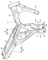
- FIG. 1 is a side view of a main part of a motorcycle.
- FIG. 2 is a perspective view of the vehicle body frame.
- (First embodiment) 3 is an enlarged view of a portion indicated by an arrow 3 in FIG.
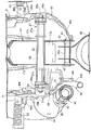
- (First embodiment) 4 is a cross-sectional view taken along line 4-4 of FIG.
- (First embodiment) 5 is a cross-sectional view taken along line 5-5 of FIG.
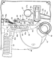
- (First embodiment) 6 is a view taken along line 6-6 in FIG.
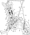
- FIG. 7 is an enlarged view of a main part of FIG. (First embodiment)
- a body frame F of a motorcycle includes a head pipe 13 that supports a front fork 11 and a steering handle 12 that pivotally support a front wheel WF, and a head pipe 13 that is rearwardly lowered from the head pipe 13.
- a main frame 14 that extends, a pair of left and right subframes 15, 15 that are connected to the main frame 14, and a front end portion of the main frame 14 that extends rearward and downward at a steeper angle than the main frame 14.
- a down frame 16 and a pivot frame 17 coupled to a rear end portion of the main frame 14 are provided.
- An engine main body 20 of the internal combustion engine E is disposed in front of the rear portion of the main frame 14 and the pivot frame 17.
- the engine body 20 is mounted on the vehicle body frame F so as to be surrounded by the main frame 14, the down frame 16, and the pivot frame 17, and an engine hanger provided at a lower end portion of the down frame 16.
- the engine body 20 is supported by 18 and the pivot frame 17.
- a fuel tank 21 is mounted on the main frame 14 above the engine body 20, and a tandem type riding seat 22 disposed behind the fuel tank 21 is supported by the sub frames 15 and 15.
- the pivot frame 17 includes a pair of left and right side plate portions 17a and 17a that are opposed to each other in the vehicle width direction and extend in the vertical direction, and a connecting plate portion 17b that connects the upper portions of the side plate portions 17a and 17a. Is formed by bending a metal plate material, and between the pair of left and right side plate portions 17a and 17a, both ends are projected outward from the side plate portions 17a and 17a.
- a swing arm support cylinder 23 is provided.
- the sub-frame 15 is configured to have a hollow closed cross-section by butt-joining the peripheral edge portions of a pair of left and right frame constituent members made of a pressed metal plate, and the sub-frame 15 includes the main frame.
- 14 has a seat rail portion 15a having a front end portion connected to the middle portion of the main body 14 and extending rearward from the main frame 14, and a rear frame portion 15b extending downward from the middle portion in the front-rear direction of the seat rail portion 15a. It is formed so as to be substantially Y-shaped in a side view.
- a first cross member 24 is provided between the seat rail portions 15a and 15a at a portion in front of the connecting portion of the rear frame portions 15b and 15b with respect to the pair of left and right seat rail portions 15a and 15a.
- a second cross member 25 is provided between the rear end portions of the portions 15a and 15a.
- the riding seat 22 is supported by the seat rail portions 15 a and 15 a of both the subframes 15 and 15, and the front end portions of the rear frame portions 15 b and 15 b are connected to the pivot frame 17.
- a portion corresponding to the connecting portion of the rear frame portions 15b, 15b to the seat rail portions 15a, 15a projects an outer end portion between the seat rail portions 15a, 15a from the seat rail portions 15a, 15a.
- the cross pipe 26 is provided.
- the front end portion of the swing arm 27 that pivotally supports the rear wheel WR at the rear end portion is swingable via a bolt 28 as a support shaft inserted through the swing arm support cylinder 23.
- Rear cushions 29 are provided between both ends of the cross pipe 26 and the swing arm 27, respectively.
- the front portion of the fuel tank 21 and both side surfaces near the front portion are covered with a shroud 30 supported by the front portion of the vehicle body frame F, and a part of the engine E, a part of the main frame 14 and the
- the front portion of the subframe 15 is supported from the side by a pair of left and right side covers 31 that are supported by the vehicle body frame F and disposed below the fuel tank 21, and the rear portion of the subframe 15 is the subframe 15.
- the rear cover 32 is supported from the side.
- the intake device 34 provided in the internal combustion engine E is connected to the rear side surface of the cylinder head 33 in the engine body 20, and the intake device 34 is connected to the subframe 15 in a side view.
- An air cleaner 35 disposed at a position surrounded by the seat rail portion 15a and the rear frame portion 15b and covered from the side by the side cover 31, a throttle body 36 connected to the air cleaner 35, the throttle body 36 and the cylinder
- An intake pipe 37 connecting the heads 33 is provided.
- a tool box 38 is provided below the air cleaner 35. The tool box 38 allows the tool to be taken in and out by opening the side cover 31.
- the exhaust device 40 provided in the internal combustion engine E is connected to the front side surface of the cylinder head 33 and extends from the front side surface of the cylinder head 33 to the rear through the lower side of the engine body 20. 41, and an exhaust muffler 42 that is arranged to extend rearward on the right side of the rear wheel WR and is connected to the downstream end of the exhaust pipe 41.
- the downstream end of the exhaust pipe 41 closer to the exhaust muffler 42 is covered with a heat insulating cover 43 attached to the exhaust pipe 41, and the exhaust muffler 42 is attached to the exhaust muffler 42 and the right step holder 49. 44.
- short cylindrical tube members 45, 45 arranged coaxially with each other are fixed to the lower inner surfaces of the side plate portions 17 a, 17 a in the pivot frame 17.
- a cylindrical portion 46a provided at a base portion 46 is disposed between the cylindrical members 45 and 45, and a stand shaft 47 is inserted into the cylindrical members 45 and 45 and the cylindrical portion 46a.
- the main stand 46 is rotatably supported by the lower portion of the pivot frame 17 via the stand shaft 47.
- the swing arm 27 has a pair of left and right arm portions 27a, 27a extending in the front-rear direction on both left and right sides of the rear wheel WR, and the front end portions of the arm portions 27a, 27a are provided on the pivot frame 17. It arrange
- Step holders 48 and 49 are disposed on the left and right outer sides of the pivot frame 17 in the vehicle width direction.
- the step holders 48 and 49 are arranged so that the front ends of the arm portions 27a and 27a of the swing arm 27 are connected to the pivot frame. 17 from the left step holder 48 side to the step holder 48, the front end portion of the left arm portion 27a, the swing arm support tube 23, and the right arm.
- the bolt 28 having the enlarged-diameter protrusion 28 a that is in contact with and engaged with the left step holder 48 from the outside is inserted into the front end portion of the portion 27 a and the right step holder 49, and the bolt from the right step holder 49 is inserted.
- a nut 50 that contacts and engages with the step holder 49 on the right side is screwed onto the protruding portion of the bolt 28.
- the pivot frame 17 is supported such that the front end portion of the swing arm 27 is swingable via the bolt 28, and a pair of left and right step holders 48 and 49 are fixed via the bolt 28.
- the step holders 48 and 49 include support portions 48a and 49a fixed to the pivot frame 17 via the bolts 28, and front and rear extension portions 48b and 49b extending rearward in the vehicle front-rear direction from the support portions 48a and 49a.
- the upper and lower extending portions 48c and 49c extending downward from the support portions 48a and 49a so as to extend to the lower side of the swing arm 27 in a side view are integrally formed.
- the vertical extension 48c of the left step holder 48 is formed so that the lower end of the vertical extension 48c is close to the lower part of the left side plate 17a of the pivot frame 17, whereas
- the vertical extension 49c of the right step holder 49 is formed so that the lower end of the vertical extension 49c is disposed at a position relatively spaced from the lower portion of the right side plate 17a of the pivot frame 17.
- a support cylinder 51 in which the protruding amount from the right side plate portion 17a is larger than the protruding amount from the left side plate portion 17a is provided on both side plate portions 17a, 17a. It is fixed so as to penetrate.
- Bolts 52 see FIGS.
- step holders 48 and 49 are attached with pillion steps 53 and 53 that allow a passenger who rides on the rear part of the riding seat 22 to put his / her feet on.
- 53 project from the step holders 48, 49 to the folding positions where the support portions 48a, 49a provided at the rear portions of the front and rear extension portions 48b, 49b are folded to the side of the step holders 48, 49 and to the sides. It can be mounted so as to be able to rotate between the protruding positions.
- a brake pedal 54 is rotatably supported on the right step holder 49 via a pedal shaft 55.
- the extending portion 49c integrally has a pedal shaft support portion 49e protruding rearward in the vehicle front-rear direction, and one end portion of the pedal shaft 55 extending in the vehicle width direction is mold-coupled to the pedal shaft support portion 49e.
- the pedal shaft 55 is disposed at least partially below the swing arm 27 in a side view and overlaps with a part of the exhaust device 40. In this embodiment, the exhaust in the exhaust device 40 is exhausted. A part of the pedal shaft 55 is disposed at the downstream end of the pipe 41 in a side view.
- the brake pedal 54 includes a cylindrical support cylinder portion 54a that is rotatably supported by the pedal shaft 55, a horizontal arm portion 54b that extends forward from the support cylinder portion 54a in the vehicle longitudinal direction, and the horizontal arm.
- a pedal portion 54c provided at the front end of the portion 54b, and a vertical arm portion 54d connected to the support cylinder portion 54a so as to extend in the vertical direction.
- the brake pedal 54 has the swing arm in a side view. 27, it is rotatably supported by the pedal shaft support portion 49e of the vertical extending portion 49c via the pedal shaft 55.
- the lateral arm portion 54b is formed of a metal pipe having a rear end portion and a front end portion that are bent upward in the vehicle front-rear direction, and the rear end portion of the metal pipe is welded to the support cylinder portion 54a.
- the vertical arm portion 54d is disposed between the swing arm 27 and the step holder 49 in the vehicle width direction so that at least an upper end portion is disposed on the back side of the front-rear extension portion 49b.
- One end portion of a return spring 56 that exerts a spring force that biases the brake pedal 54 toward the return side is connected to the rear end portion of the lateral arm portion 54 b of the brake pedal 54, and the other end portion of the return spring 56. Is connected to the lower end of the vertically extending portion 49 c of the step holder 49.
- a stopper 57 for restricting the return end of the brake pedal 54 is attached to the lower portion of the step holder 49.
- the lower end of the vertically extending portion 49c of the step holder 49 is provided.
- the stopper 57 is attached to the portion by a bolt 58 and a nut 59.
- a brake lever 61 is attached to the right end portion of the steering handle 12 so as to be capable of rotating, and a brake hydraulic pressure is output according to the rotating operation of the brake lever 61.
- a master cylinder 62 is attached.
- the front wheel WF is provided with a disc brake B1 which is braked according to the operation of the brake lever 61 and also braked by the depression of the brake pedal 54, and the rear wheel WR is depressed of the brake pedal 54.
- a drum brake B2 is provided that is braked by operation.
- a second master cylinder 63 capable of generating a hydraulic pressure for operating the disc brake B ⁇ b> 1 is disposed on the back side of the right step holder 49.
- the second master cylinder 63 is attached to the back side of the front part of the front-rear extension part 49b in the step holder 49 while slightly tilting forward.
- the second master cylinder 63 is attached to the back surface of the front part of the front-rear extension part 49b by a pair of bolts 64, 64.
- the operation force by the brake pedal 54 is input to the second master cylinder 63 via the equalizer 65, and as a brake operation force transmission member that mechanically transmits the brake operation force to the drum brake B2 of the rear wheel WR.
- the intermediate portion of the equalizer 65 is also connected to the upper end portion of the vertical arm portion 54d on the rear side of the vertical arm portion 54d of the brake pedal 54 via a shaft 67 so as to be rotatable. Is done.
- the piston rod 68 of the second master cylinder 63 disposed in front of the equalizer 65 is connected to the upper end portion of the equalizer 65 via a connection pin 69.
- One end of the rod 66 is connected to the lower end of the equalizer 65 via a connecting pin 70, and the other end of the rod 66 is input to the drum brake B2 as clearly shown in FIG.
- the tip of the arm 71 is connected via a connecting pin 72.
- the piston rod 68 of the second master cylinder 63 is pushed in after the equalizer 65 is actuated so as to pull the rod 66 in response to the depression operation of the brake pedal 54.
- the delay spring 73 for controlling the relative posture of the equalizer 65 with respect to the vertical arm portion 54d at the initial stage of the depression operation of the brake pedal 54 is provided, and the upper end portion side of the equalizer 65 and the front-rear extension portion are provided.
- the delay spring 73 interposed between the rear part of 49b extends along the longitudinal direction of the front / rear extension part 49b and is disposed on the back side of the front / rear extension part 49b.
- the hydraulic hose 75 that guides the hydraulic pressure output from the second master cylinder 63 is connected to the caliper 76 of the disc brake B1 of the front wheel WF via the right side cover 31 and the shroud 30.
- a hydraulic hose 77 that guides the hydraulic pressure from the first master cylinder 62 is also connected to the caliper 76.
- the lower edge 31a of the right side cover 31 is disposed along the upper edge 49f while covering at least the upper edge 49f of the right step holder 49 from the outside.
- 63 is also arranged so that a part thereof protrudes from the back side of the right step holder 49 into the right side cover 31, and the hydraulic hose 75 is connected to the second master cylinder 63 in the side cover 31. Is done.
- a reservoir 78 for supplying brake fluid to the second master cylinder 63 is disposed at the front upper side of the second master cylinder 63, and the reservoir 78 is disposed on the vehicle body frame F. It is supported by a stay 79 fixed to the main frame 14.
- the reservoir 78 is connected to the second master cylinder 63 by a hose 80 that guides brake fluid.
- the reservoir 78 is formed of a transparent synthetic resin so that the storage level of the brake fluid stored in the reservoir 78 can be visually recognized from the outside, and the right side cover 31 that covers the reservoir 78 from the outside.
- An inspection window 81 is formed in which a part of the reservoir 78 is visible from the outside.
- a brake switch 84 for detecting the operation of the brake pedal 54 is attached to the right step holder 49, and the brake switch 84 extends in the front-rear direction in the step holder 49. It extends long along the longitudinal direction of the protruding portion 49b and is supported by the rear rear surface of the front-rear extending portion 49b. That is, a support plate portion 49g is integrally projected on the rear rear surface of the front-rear extension portion 49b, and the brake switch 84 is inserted and supported by the support plate portion 49g.
- the brake switch 84 is connected to the upper end portion of the vertical arm portion 54d of the brake pedal 54.
- the hook is engaged with and connected to the upper end portion of the vertical arm portion 54d.
- the other end of the connecting rod 85 having the portion 85 a at one end is connected to the brake switch 84 via a spring 86.
- the brake switch cable 87 extended from the brake switch 84 is routed so that the back side of the upper part of the front and rear extension 49b extends forward, and a part of the brake switch cable 87 is It is supported on the back side of the front and rear extension 49b by two cable holders 88 and 89 attached to the upper back of the front and rear extension 49b.
- a clip 90 is attached to the back surface of the front and rear extension 49b of the step holder 49 in front of the cable holder 89 on the front side of the two cable holders 88 and 89 by a bolt 90 that is a fastening member oriented in the vehicle width direction.
- the support member 91 is fastened, and a support surface 93 that faces the front or rear (rear in this embodiment) along the vehicle front-rear direction is formed on the clip support member 91 and is supported by the support surface 93.
- the brake switch cable 87 is held.
- the clip support member 91 integrally includes a mounting plate portion 91a fastened to the back surface of the front / rear extension portion 49b by the bolt 90 and a support plate portion 91b provided continuously to the mounting plate portion 91a.
- the support surface 93 is formed on the support plate portion 91b.
- a pair of protrusions 94 and 95 that sandwich the mounting plate 91a from the front and rear are integrally formed on the back surface of the front and rear extension 49b, and are sandwiched between the protrusions 94 and 95. Since the attachment plate portion 91a is prevented from rotating, the clip support member 91 can be fastened to the front-rear extension portion 49b with only a single bolt 90.
- the rear protrusion 95 is disposed at a position facing the vertical arm 54d of the brake pedal 54 from the front, and when the brake pedal 54 is fully depressed.
- the maximum rotation position of the brake pedal 54 is regulated by contacting the vertical arm portion 54d.
- a pillion step 53 that allows a passenger to put his / her foot on is attached to the right step holder 49 fixed to the vehicle body frame F, and the brake pedal 54 is connected to the pedal shaft.
- a brake switch 84 that is rotatably supported via 55 and detects the operation of the brake pedal 54 is attached to the step holder 49.
- the step holder 49 is attached to the pivot frame 17 via a bolt 28.
- a fixed support part 49a and a front / rear extension part 49b extending rearward in the vehicle front-rear direction from the support part 49a are integrally formed, and the brake pedal 54 has at least an upper end portion of the front / rear extension part 49b.
- the step holder 49 While avoiding an increase in size and an increase in the number of parts, the design can be improved by preventing the brake switch 84 from being seen from the outside, and mischief to the brake switch 84 can be prevented.
- the brake switch cable 87 since a part of the brake switch cable 87 extending from the brake switch 84 is supported on the back side of the front / rear extending portion 49b, the brake switch cable 87 is not exposed to the outside in the vicinity of the brake switch 84, The design can be further improved, and mischief to the brake switch cable 87 can be prevented.
- the step holder 49 is integrally formed with a vertically extending portion 49c extending downward from the support portion 49a, and exerts a spring force to bias the brake pedal 54 toward the return side. Since the other end portion of the return spring 56 to which the portion is connected is connected to the lower end portion of the vertically extending portion 49c, the return spring 56 is disposed in the vicinity of the step holder 49 where the space in the vertical direction is limited. Can be prevented from being enlarged.
- the brake switch 84 is connected to the front upper end of the vertical arm portion 54d, the stroke length of the brake switch 84 extending long along the longitudinal direction of the front / rear extending portion 49b can be ensured.
- the brake The switch cable 87 is extended from the step holder 49 to the back side of the side cover 31 so that the brake switch cable 87 is not exposed to the outside as much as possible to improve the design and prevent mischief to the brake switch cable 87. The effect can be further enhanced.
- a clip support member 91 that causes a support surface 93 that supports the cable clip 92 that holds the brake switch cable 87 to face rearward in the vehicle front-rear direction is extended by the bolt 90 directed in the vehicle width direction in the step holder 49. Since it is fastened to the back surface of the protruding portion 49b, the cable switch 92 can be used to change the direction in which the brake switch cable 87 extends in the vehicle front-rear direction to the vehicle width direction, and the bolt 90 that fastens the clip support member 91 Since it is oriented in the vehicle width direction, the processing applied to the step holder 49 to attach the clip support member 91 is facilitated.
- the vertically extending portion 49 c of the step holder 49 extends downward from the support portion 49 a so as to extend below the swing arm 27 in a side view, and a side surface of a part of the exhaust device 40 of the internal combustion engine E.
- At least a part of the pedal shaft 55 is arranged at a position overlapping in view, and is supported rotatably on the vertical extension portion 49c via the pedal shaft 55 below the swing arm 27 in side view.
- the brake pedal 54 is formed to have a vertical arm portion 54d extending vertically so as to be disposed between the swing arm 27 and the step holder 49 in the vehicle width direction. Even if the exhaust device 40 is provided, the brake pedal 54 can be supported by the step holder 49 with a sufficient supporting force.
- a brake is applied to the second master cylinder 63 attached to the step holder 49 and the drum brake B2 provided to the rear wheel WR so as to be able to generate a hydraulic pressure for operating the disc brake B1 provided on the front wheel WF. Since the brake operation force input from the brake pedal 54 is distributed to the rod 66 that mechanically transmits the operation force by the equalizer 65, the disc brake B1 of the front wheel WF and the rear wheel are operated by the operation of the brake pedal 54.
- An interlocking brake can be configured in which the brake is operated in conjunction with the WR drum brake B2.
- An intermediate portion of the equalizer 65 having one end connected to the second master cylinder 63 and the other end connected to the rod 66 is connected to the vertical arm 54d on the back side of the vertical arm 54d. Therefore, the rod 66 can be disposed as close as possible to the swing arm 27 side, and the rod 66 can be disposed closer to the drum brake B2 of the rear wheel WR in the vehicle width direction.
- the step holder 49 has integrally and extends rearward in the vehicle front-rear direction, along the longitudinal direction of the front / rear extension part 49b. Since the delay spring 73 that extends and is disposed on the back side of the front-rear extension portion 49b is interposed, the length of the delay spring 73 can be ensured and the necessary spring force can be ensured while enhancing the design.
- the stopper 57 for restricting the rotation end of the return side of the brake pedal 54 is attached to the lower portion of the step holder 49, the entire step holder 49 including the stopper 57 can be unitized and assembled. Can be increased.
Landscapes
- Engineering & Computer Science (AREA)
- Mechanical Engineering (AREA)
- Braking Elements And Transmission Devices (AREA)
- Mechanical Control Devices (AREA)
- Body Structure For Vehicles (AREA)
- Transmission Of Braking Force In Braking Systems (AREA)
- Motorcycle And Bicycle Frame (AREA)
- Automatic Cycles, And Cycles In General (AREA)
Priority Applications (4)
| Application Number | Priority Date | Filing Date | Title |
|---|---|---|---|
| JP2015534030A JP6077662B2 (ja) | 2013-08-29 | 2014-05-27 | 自動二輪車 |
| CN201480048113.7A CN105517883B (zh) | 2013-08-29 | 2014-05-27 | 两轮摩托车 |
| BR112016003548-8A BR112016003548B1 (pt) | 2013-08-29 | 2014-05-27 | Veículo de duas rodas automático |
| PH12016500370A PH12016500370B1 (en) | 2013-08-29 | 2016-02-24 | Automatic two-wheeled vehicle |
Applications Claiming Priority (2)
| Application Number | Priority Date | Filing Date | Title |
|---|---|---|---|
| JP2013-177804 | 2013-08-29 | ||
| JP2013177804 | 2013-08-29 |
Publications (1)
| Publication Number | Publication Date |
|---|---|
| WO2015029520A1 true WO2015029520A1 (ja) | 2015-03-05 |
Family
ID=52586101
Family Applications (1)
| Application Number | Title | Priority Date | Filing Date |
|---|---|---|---|
| PCT/JP2014/063969 Ceased WO2015029520A1 (ja) | 2013-08-29 | 2014-05-27 | 自動二輪車 |
Country Status (6)
| Country | Link |
|---|---|
| JP (1) | JP6077662B2 (enExample) |
| CN (1) | CN105517883B (enExample) |
| BR (1) | BR112016003548B1 (enExample) |
| MY (1) | MY177121A (enExample) |
| PH (1) | PH12016500370B1 (enExample) |
| WO (1) | WO2015029520A1 (enExample) |
Cited By (5)
| Publication number | Priority date | Publication date | Assignee | Title |
|---|---|---|---|---|
| EP3225521A3 (en) * | 2016-03-31 | 2017-10-25 | Honda Motor Co., Ltd. | Reservoir tank mounting structure of saddle riding vehicle |
| WO2018142575A1 (ja) * | 2017-02-03 | 2018-08-09 | 本田技研工業株式会社 | 鞍乗型車両の前後連動ブレーキ装置 |
| WO2019138428A1 (en) * | 2018-01-12 | 2019-07-18 | Hero MotoCorp Limited | Speed deceleration system of vehicle |
| EP3569485A4 (en) * | 2017-01-12 | 2020-01-22 | Honda Motor Co., Ltd. | TRANSMISSION FOR SADDLE VEHICLE |
| JP2025090444A (ja) * | 2023-12-05 | 2025-06-17 | 本田技研工業株式会社 | 鞍乗り型車両 |
Citations (3)
| Publication number | Priority date | Publication date | Assignee | Title |
|---|---|---|---|---|
| JP2010234940A (ja) * | 2009-03-31 | 2010-10-21 | Honda Motor Co Ltd | 鞍乗り型車両 |
| JP2011143767A (ja) * | 2010-01-13 | 2011-07-28 | Honda Motor Co Ltd | 自動二輪車用連動制動装置 |
| JP2013154845A (ja) * | 2012-01-31 | 2013-08-15 | Honda Motor Co Ltd | 自動二輪車用制動装置 |
Family Cites Families (1)
| Publication number | Priority date | Publication date | Assignee | Title |
|---|---|---|---|---|
| JP2845838B2 (ja) * | 1996-09-19 | 1999-01-13 | 静岡日本電気株式会社 | 無線選択呼出受信機 |
-
2014
- 2014-05-27 JP JP2015534030A patent/JP6077662B2/ja active Active
- 2014-05-27 BR BR112016003548-8A patent/BR112016003548B1/pt active IP Right Grant
- 2014-05-27 WO PCT/JP2014/063969 patent/WO2015029520A1/ja not_active Ceased
- 2014-05-27 CN CN201480048113.7A patent/CN105517883B/zh active Active
- 2014-05-27 MY MYPI2016700646A patent/MY177121A/en unknown
-
2016
- 2016-02-24 PH PH12016500370A patent/PH12016500370B1/en unknown
Patent Citations (3)
| Publication number | Priority date | Publication date | Assignee | Title |
|---|---|---|---|---|
| JP2010234940A (ja) * | 2009-03-31 | 2010-10-21 | Honda Motor Co Ltd | 鞍乗り型車両 |
| JP2011143767A (ja) * | 2010-01-13 | 2011-07-28 | Honda Motor Co Ltd | 自動二輪車用連動制動装置 |
| JP2013154845A (ja) * | 2012-01-31 | 2013-08-15 | Honda Motor Co Ltd | 自動二輪車用制動装置 |
Cited By (11)
| Publication number | Priority date | Publication date | Assignee | Title |
|---|---|---|---|---|
| EP3225521A3 (en) * | 2016-03-31 | 2017-10-25 | Honda Motor Co., Ltd. | Reservoir tank mounting structure of saddle riding vehicle |
| US9956945B2 (en) | 2016-03-31 | 2018-05-01 | Honda Motor Co., Ltd. | Reservoir tank mounting structure of saddle riding vehicle |
| EP3569485A4 (en) * | 2017-01-12 | 2020-01-22 | Honda Motor Co., Ltd. | TRANSMISSION FOR SADDLE VEHICLE |
| US11072393B2 (en) | 2017-01-12 | 2021-07-27 | Honda Motor Co., Ltd. | Transmission for saddled vehicle |
| WO2018142575A1 (ja) * | 2017-02-03 | 2018-08-09 | 本田技研工業株式会社 | 鞍乗型車両の前後連動ブレーキ装置 |
| CN110248865A (zh) * | 2017-02-03 | 2019-09-17 | 本田技研工业株式会社 | 鞍乘型车辆的前后连动制动装置 |
| JPWO2018142575A1 (ja) * | 2017-02-03 | 2019-11-07 | 本田技研工業株式会社 | 鞍乗型車両の前後連動ブレーキ装置 |
| CN110248865B (zh) * | 2017-02-03 | 2021-03-09 | 本田技研工业株式会社 | 鞍乘型车辆的前后连动制动装置 |
| WO2019138428A1 (en) * | 2018-01-12 | 2019-07-18 | Hero MotoCorp Limited | Speed deceleration system of vehicle |
| JP2025090444A (ja) * | 2023-12-05 | 2025-06-17 | 本田技研工業株式会社 | 鞍乗り型車両 |
| JP7765446B2 (ja) | 2023-12-05 | 2025-11-06 | 本田技研工業株式会社 | 鞍乗り型車両 |
Also Published As
| Publication number | Publication date |
|---|---|
| JPWO2015029520A1 (ja) | 2017-03-02 |
| PH12016500370A1 (en) | 2016-05-02 |
| PH12016500370B1 (en) | 2016-05-02 |
| BR112016003548A2 (enExample) | 2017-08-01 |
| MY177121A (en) | 2020-09-07 |
| BR112016003548B1 (pt) | 2022-01-04 |
| JP6077662B2 (ja) | 2017-02-15 |
| CN105517883A (zh) | 2016-04-20 |
| CN105517883B (zh) | 2018-05-01 |
Similar Documents
| Publication | Publication Date | Title |
|---|---|---|
| JP6141924B2 (ja) | 自動二輪車におけるステップ構造 | |
| JP6077662B2 (ja) | 自動二輪車 | |
| CN101624083A (zh) | 机动二轮车的车身罩结构 | |
| US8393630B2 (en) | Straddle-type vehicle | |
| JP2014080057A (ja) | 自動二輪車のリヤブレーキ装置 | |
| JP4825543B2 (ja) | ブレーキ支持構造 | |
| JP5848294B2 (ja) | 自動二輪車 | |
| JP4612005B2 (ja) | スクータ型車両のフットブレーキ構造 | |
| JP6244321B2 (ja) | 自動二輪車 | |
| CN110843972B (zh) | 跨骑式车辆 | |
| CN108883807B (zh) | 鞍乘式车辆 | |
| TW202041404A (zh) | 跨坐型車輛 | |
| WO2017056281A1 (ja) | 鞍乗り型車両の連動ブレーキ装置 | |
| JP6839301B2 (ja) | 鞍乗型車両のブレーキ配管構造 | |
| JP3433912B2 (ja) | 操作レバー調節装置 | |
| JP2009090892A (ja) | 鞍乗型車両 | |
| JP6166333B2 (ja) | 鞍乗り型車両のハーネスガイド構造 | |
| TW201615479A (zh) | 跨騎型車輛的煞車總泵配設構造 | |
| JP6761487B2 (ja) | 鞍乗型車両 | |
| JP6710718B2 (ja) | 鞍乗り型車両 | |
| JP2005240885A (ja) | 車両のディスクブレーキにおけるパッド残量確認構造 | |
| JP7787221B2 (ja) | 鞍乗り型車両 | |
| JP7602663B2 (ja) | 鞍乗型車両 | |
| JPWO2018198827A1 (ja) | 鞍乗り型車両の前後連動ブレーキ装置 | |
| WO2015129439A1 (ja) | 自動二輪車における制動力伝達部材の配索構造 |
Legal Events
| Date | Code | Title | Description |
|---|---|---|---|
| 121 | Ep: the epo has been informed by wipo that ep was designated in this application |
Ref document number: 14840759 Country of ref document: EP Kind code of ref document: A1 |
|
| DPE1 | Request for preliminary examination filed after expiration of 19th month from priority date (pct application filed from 20040101) | ||
| ENP | Entry into the national phase |
Ref document number: 2015534030 Country of ref document: JP Kind code of ref document: A |
|
| WWE | Wipo information: entry into national phase |
Ref document number: 12016500370 Country of ref document: PH |
|
| NENP | Non-entry into the national phase |
Ref country code: DE |
|
| REG | Reference to national code |
Ref country code: BR Ref legal event code: B01A Ref document number: 112016003548 Country of ref document: BR |
|
| WWE | Wipo information: entry into national phase |
Ref document number: IDP00201601747 Country of ref document: ID |
|
| 122 | Ep: pct application non-entry in european phase |
Ref document number: 14840759 Country of ref document: EP Kind code of ref document: A1 |
|
| ENP | Entry into the national phase |
Ref document number: 112016003548 Country of ref document: BR Kind code of ref document: A2 Effective date: 20160219 |