WO2015025439A1 - 作業車両の表示装置及びその表示方法 - Google Patents
作業車両の表示装置及びその表示方法 Download PDFInfo
- Publication number
- WO2015025439A1 WO2015025439A1 PCT/JP2013/081217 JP2013081217W WO2015025439A1 WO 2015025439 A1 WO2015025439 A1 WO 2015025439A1 JP 2013081217 W JP2013081217 W JP 2013081217W WO 2015025439 A1 WO2015025439 A1 WO 2015025439A1
- Authority
- WO
- WIPO (PCT)
- Prior art keywords
- display
- display screen
- screen
- displayed
- temporary
- Prior art date
- Legal status (The legal status is an assumption and is not a legal conclusion. Google has not performed a legal analysis and makes no representation as to the accuracy of the status listed.)
- Ceased
Links
Images

Classifications
-
- B—PERFORMING OPERATIONS; TRANSPORTING
- B60—VEHICLES IN GENERAL
- B60R—VEHICLES, VEHICLE FITTINGS, OR VEHICLE PARTS, NOT OTHERWISE PROVIDED FOR
- B60R16/00—Electric or fluid circuits specially adapted for vehicles and not otherwise provided for; Arrangement of elements of electric or fluid circuits specially adapted for vehicles and not otherwise provided for
- B60R16/02—Electric or fluid circuits specially adapted for vehicles and not otherwise provided for; Arrangement of elements of electric or fluid circuits specially adapted for vehicles and not otherwise provided for electric constitutive elements
-
- E—FIXED CONSTRUCTIONS
- E02—HYDRAULIC ENGINEERING; FOUNDATIONS; SOIL SHIFTING
- E02F—DREDGING; SOIL-SHIFTING
- E02F9/00—Component parts of dredgers or soil-shifting machines, not restricted to one of the kinds covered by groups E02F3/00 - E02F7/00
- E02F9/26—Indicating devices
-
- B—PERFORMING OPERATIONS; TRANSPORTING
- B60—VEHICLES IN GENERAL
- B60R—VEHICLES, VEHICLE FITTINGS, OR VEHICLE PARTS, NOT OTHERWISE PROVIDED FOR
- B60R1/00—Optical viewing arrangements; Real-time viewing arrangements for drivers or passengers using optical image capturing systems, e.g. cameras or video systems specially adapted for use in or on vehicles
- B60R1/20—Real-time viewing arrangements for drivers or passengers using optical image capturing systems, e.g. cameras or video systems specially adapted for use in or on vehicles
- B60R1/22—Real-time viewing arrangements for drivers or passengers using optical image capturing systems, e.g. cameras or video systems specially adapted for use in or on vehicles for viewing an area outside the vehicle, e.g. the exterior of the vehicle
- B60R1/23—Real-time viewing arrangements for drivers or passengers using optical image capturing systems, e.g. cameras or video systems specially adapted for use in or on vehicles for viewing an area outside the vehicle, e.g. the exterior of the vehicle with a predetermined field of view
- B60R1/26—Real-time viewing arrangements for drivers or passengers using optical image capturing systems, e.g. cameras or video systems specially adapted for use in or on vehicles for viewing an area outside the vehicle, e.g. the exterior of the vehicle with a predetermined field of view to the rear of the vehicle
-
- E—FIXED CONSTRUCTIONS
- E02—HYDRAULIC ENGINEERING; FOUNDATIONS; SOIL SHIFTING
- E02F—DREDGING; SOIL-SHIFTING
- E02F3/00—Dredgers; Soil-shifting machines
- E02F3/04—Dredgers; Soil-shifting machines mechanically-driven
- E02F3/28—Dredgers; Soil-shifting machines mechanically-driven with digging tools mounted on a dipper- or bucket-arm, i.e. there is either one arm or a pair of arms, e.g. dippers, buckets
- E02F3/30—Dredgers; Soil-shifting machines mechanically-driven with digging tools mounted on a dipper- or bucket-arm, i.e. there is either one arm or a pair of arms, e.g. dippers, buckets with a dipper-arm pivoted on a cantilever beam, i.e. boom
- E02F3/32—Dredgers; Soil-shifting machines mechanically-driven with digging tools mounted on a dipper- or bucket-arm, i.e. there is either one arm or a pair of arms, e.g. dippers, buckets with a dipper-arm pivoted on a cantilever beam, i.e. boom working downwardly and towards the machine, e.g. with backhoes
-
- E—FIXED CONSTRUCTIONS
- E02—HYDRAULIC ENGINEERING; FOUNDATIONS; SOIL SHIFTING
- E02F—DREDGING; SOIL-SHIFTING
- E02F9/00—Component parts of dredgers or soil-shifting machines, not restricted to one of the kinds covered by groups E02F3/00 - E02F7/00
- E02F9/26—Indicating devices
- E02F9/261—Surveying the work-site to be treated
-
- G—PHYSICS
- G06—COMPUTING OR CALCULATING; COUNTING
- G06F—ELECTRIC DIGITAL DATA PROCESSING
- G06F3/00—Input arrangements for transferring data to be processed into a form capable of being handled by the computer; Output arrangements for transferring data from processing unit to output unit, e.g. interface arrangements
- G06F3/14—Digital output to display device ; Cooperation and interconnection of the display device with other functional units
-
- H—ELECTRICITY
- H04—ELECTRIC COMMUNICATION TECHNIQUE
- H04N—PICTORIAL COMMUNICATION, e.g. TELEVISION
- H04N7/00—Television systems
- H04N7/18—Closed-circuit television [CCTV] systems, i.e. systems in which the video signal is not broadcast
- H04N7/183—Closed-circuit television [CCTV] systems, i.e. systems in which the video signal is not broadcast for receiving images from a single remote source
-
- B—PERFORMING OPERATIONS; TRANSPORTING
- B60—VEHICLES IN GENERAL
- B60R—VEHICLES, VEHICLE FITTINGS, OR VEHICLE PARTS, NOT OTHERWISE PROVIDED FOR
- B60R2300/00—Details of viewing arrangements using cameras and displays, specially adapted for use in a vehicle
- B60R2300/20—Details of viewing arrangements using cameras and displays, specially adapted for use in a vehicle characterised by the type of display used
- B60R2300/207—Details of viewing arrangements using cameras and displays, specially adapted for use in a vehicle characterised by the type of display used using multi-purpose displays, e.g. camera image and navigation or video on same display
-
- B—PERFORMING OPERATIONS; TRANSPORTING
- B60—VEHICLES IN GENERAL
- B60R—VEHICLES, VEHICLE FITTINGS, OR VEHICLE PARTS, NOT OTHERWISE PROVIDED FOR
- B60R2300/00—Details of viewing arrangements using cameras and displays, specially adapted for use in a vehicle
- B60R2300/80—Details of viewing arrangements using cameras and displays, specially adapted for use in a vehicle characterised by the intended use of the viewing arrangement
- B60R2300/8006—Details of viewing arrangements using cameras and displays, specially adapted for use in a vehicle characterised by the intended use of the viewing arrangement for monitoring and displaying scenes of vehicle interior, e.g. for monitoring passengers or cargo
-
- B—PERFORMING OPERATIONS; TRANSPORTING
- B60—VEHICLES IN GENERAL
- B60R—VEHICLES, VEHICLE FITTINGS, OR VEHICLE PARTS, NOT OTHERWISE PROVIDED FOR
- B60R2300/00—Details of viewing arrangements using cameras and displays, specially adapted for use in a vehicle
- B60R2300/80—Details of viewing arrangements using cameras and displays, specially adapted for use in a vehicle characterised by the intended use of the viewing arrangement
- B60R2300/802—Details of viewing arrangements using cameras and displays, specially adapted for use in a vehicle characterised by the intended use of the viewing arrangement for monitoring and displaying vehicle exterior blind spot views
Definitions
- the present invention relates to a display device for a work vehicle and a display method therefor, which can surely make an operator aware of display of a display screen including a video screen when the work vehicle is traveling or working.
- a camera is installed at the rear of the upper turning body of the work vehicle so that the image captured by the camera can be displayed as a standard screen on the display screen of the display device provided in the cab.
- the operator can check an area with poor visibility through the display screen when the work vehicle moves backward or the upper turning body turns.
- Patent Document 1 a camera image of a rear view obtained by a camera is displayed on the entire surface of a display screen, and a measurement data image is superimposed on the camera image. It is displayed as follows.
- the operator will run or work by visual observation as it is, and it will be unfamiliar without being aware of the rear or side confirmation of the vehicle. End up. It is preferable that the operator confirms an image screen such as the rear as well as visual observation when the work vehicle is traveling or working.
- This invention is made in view of the above, Comprising: The display apparatus of the working vehicle which can perform the consciousness of the display of a display screen including a video screen with respect to an operator at the time of driving
- a display device for a work vehicle includes a plurality of first display screens including a video display area and a second display screen not including a video display area.
- a display device for a work vehicle capable of sequentially switching and displaying a display screen by operating a screen changeover switch, and switching to the first display screen when switching from the first display screen to the second display screen.
- a temporary second display screen displaying caution information for prompting display is displayed.
- the temporary second display screen displays caution information for prompting switching to the first display screen on the second display screen. It is characterized by being.
- the work vehicle display device displays the temporary second display screen and the temporary display when switching from the first display screen to the second display screen.
- the first display screen is automatically switched and displayed.
- the attention information when the confirmation switch for the attention information is pressed in a state where the temporary second display screen is displayed, the attention information is deleted. A second display screen is displayed.
- the screen changeover switch when the screen changeover switch is pressed in a state where the temporary second display screen is displayed, the first display screen is displayed.
- the screen changeover switch when the transition from the first display screen to the temporary second display screen is made, the screen changeover switch is pressed to press the screen display switch.
- a transition is made to a third display screen that displays the entire video display area, and further, the transition from the third display screen to the temporary second display screen is made by pressing a screen changeover switch.
- the first display screen is an initial standard display screen displayed after a key switch is turned on.
- the work vehicle display device sequentially switches and displays a plurality of display screens including a first display screen including a video display area and a second display screen not including the video display area by operating a screen switch.
- a display device for a work vehicle that can display the video display area from the first display screen when the screen changeover switch is pressed when transitioning from the first display screen to the second display screen.
- the third display screen is transferred to the first display screen on the second display screen.
- the confirmation switch for the caution information is pressed, It displays the second display screen clearing the meaning information, while displaying the temporary second display screen, if the screen change switch is depressed, and displaying the first display screen.
- a plurality of display screens including a first display screen including a video display area and a second display screen not including a video display area are displayed by operating a screen changeover switch.
- a display method of a display device for a work vehicle that can be sequentially switched and displayed. When switching display from the first display screen to the second display screen, attention information that prompts switching display to the first display screen is displayed. The displayed temporary second display screen is displayed.
- the temporary second display screen is caution information that prompts switching display to the first display screen on the second display screen. Is displayed.
- the temporary second display screen is displayed.
- the first display screen is automatically switched and displayed.
- the display method of the display device for a work vehicle in the above invention, when the confirmation switch for the caution information is pressed while the temporary second display screen is displayed, the caution information is displayed. The erased second display screen is displayed.
- the first display screen is displayed when a screen changeover switch is pressed in a state where the temporary second display screen is displayed. It is characterized by doing.
- the first display is performed by pressing the screen switch.
- a transition is made from the screen to a third display screen that displays the entire video display area, and when the screen switch is pressed, the transition from the third display screen to the temporary second display screen is performed.
- the display method of the display device for a work vehicle according to the present invention is characterized in that, in the above invention, the first display screen is an initial standard display screen displayed after a key switch is turned on.
- the temporary information displaying the caution information for prompting the switching display to the first display screen is displayed. Since the second display screen is displayed, the operator can be surely aware of the display of the first display screen when the work vehicle is traveling or working.
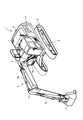
- FIG. 1 is a perspective view showing the overall configuration of a work vehicle equipped with a work vehicle display device according to an embodiment of the present invention.
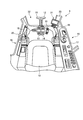
- FIG. 2 is a perspective view showing an internal configuration of the cab.
- FIG. 3 is a block diagram illustrating a functional configuration of the display device and a configuration of a main part of the control system centering on the display device.
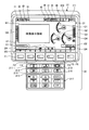
- FIG. 4 is a diagram illustrating an external configuration of the display device.
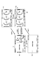
- FIG. 5 is a state transition diagram showing display screen transition of the standard screen.
- FIG. 6 is a flowchart showing the display screen transition control processing procedure of the standard screen by the display control unit.
- FIG. 1 is a perspective view showing the overall configuration of a work vehicle equipped with a work vehicle display device according to an embodiment of the present invention.
- This work vehicle is a hydraulic excavator 1 shown as an example of the work vehicle.
- the excavator 1 includes a lower traveling body 2 having a crawler belt, an upper revolving body 3 that is turnably mounted on an upper portion of the lower traveling body 2, and a work machine 4 that is coupled to the upper revolving body 3.
- the work machine 4 has a base 5 operatively connected to the upper swing body 3, an arm 6 operably connected to the tip of the boom 5, and an operably connected to the tip of the arm 6.
- the upper swing body 3 includes a cab 8 and the like.
- a camera 9 that captures an image of the rear of the excavator 1 is provided at the rear of the upper swing body 3, for example, at the upper portion of the counterweight.
- the camera 9 is an imaging unit that captures an image of an area that is not visually recognized by an operator who has boarded the cab 8 of the excavator 1, for example, an area behind the excavator 1.
- the installation position and the number of cameras 9 can be arbitrarily selected as necessary.
- a particulate matter removing filter referred to as DPF that removes particulate matter (PM) contained in the exhaust gas of the engine (DPF: Diesel Particulate Filter).
- a post-processing device such as a urea SCR (Selective Catalytic Reduction) device that catalytically reduces nitrogen oxides in exhaust gas is provided.
- a post-processing device such as a urea SCR (Selective Catalytic Reduction) device that catalytically reduces nitrogen oxides in exhaust gas.
- the volume of the engine room is increased, the height of the engine room is increased, and visibility of the rear part by the operator is deteriorated.
- the operator can compensate for the reduction in visual recognition of the rear portion by the rear or side captured image captured by the camera 9 described above.
- FIG. 2 is a perspective view showing an internal configuration of the cab 8.
- the driver's cab 8 is provided with a driver's seat 10 at the center thereof.
- Travel levers 11 and 12 and travel pedals 13 and 14 that operate integrally with the travel levers 11 and 12 are provided in front of the driver's seat 10.
- An attachment pedal 15 is provided in the vicinity of the travel pedals 13 and 14.
- An instrument panel 17 is provided in the vicinity of the right side window 16 in FIG.
- Work implement levers 18 and 19 are installed on the left and right sides of the driver's seat 10, respectively.
- the work implement lever 18 is disposed on the left hand side when the operator is seated on the driver's seat 10, and the work implement lever 19 is disposed on the right hand side on the opposite side. If the work implement lever 18 is tilted left and right in the drawing, the upper swing body 3 can be turned left and right. Further, if the work implement lever 18 is tilted back and forth (up and down) in the drawing, the arm cylinder 6a shown in FIG. 1 can be extended and retracted to move the arm 6 back and forth.
- the bucket 7 can be rotated about the tip of the arm 6 by driving the bucket cylinder 7a shown in FIG.
- the boom cylinder 5a shown in FIG. 1 can be driven to lower the boom 5 and raise the boom 5.
- the work implement lever 18 can perform the turning of the upper swing body 3 and the operation of the arm 6 simultaneously by tilting obliquely. Further, the work implement lever 19 can simultaneously operate the bucket 7 and the boom 5 by tilting obliquely.
- a lock lever 20 is provided in the vicinity of the work machine lever 18.
- the lock lever 20 is for stopping functions such as operation of the work implement 4, turning of the upper revolving structure 3, and traveling of the lower traveling structure 2. That is, by operating the lock lever 20 to be lowered, the movement of the work implement 4 and the like can be locked (restricted). In a state where the movement of the work implement 4 or the like is locked by the lock lever 20, even if the operator operates the work implement levers 18 and 19 or the like, the work implement 4 or the like does not operate.
- Various states of the excavator 1 for example, the temperature of engine cooling water, the temperature of hydraulic oil, the amount of remaining fuel, etc.
- a display device 21 for displaying a rear camera image and the like.
- FIG. 3 is a block diagram illustrating a functional configuration of the display device 21 and a configuration of a main part of the control system centering on the display device 21.
- the display device 21 is realized by using an input unit 32 into which various instructions or information are input by a hydraulic excavator operator such as an operator or a service person, and a liquid crystal screen, and various types of information including information regarding the operation of the hydraulic excavator 1.
- a display control unit 33 that is realized using a CPU or the like and controls the state of the screen displayed on the display unit 31 of the display device 21.
- the camera 9 is connected to the display device 21.
- the image pickup signal input from the camera 9 is subjected to image processing by the display control unit 33 and can be displayed on the display unit 31.
- an alarm buzzer 34 is connected to the display device 21.
- the alarm buzzer 34 generates an alarm sound based on a signal output from the display device 21.
- the pump controller C, the display device 21, and other controllers are connected to an in-vehicle network CN (Local Area Network) such as CAN (Controller Area Network). They are connected and can exchange information with each other.
- CN Local Area Network
- CAN Controller Area Network
- the pump controller C adjusts the flow rate of hydraulic oil discharged from a hydraulic pump (not shown) based on the operation amounts of the operation levers such as the travel levers 11 and 12 and the work machine levers 18 and 19, and the boom cylinder 5a and arm Drive control of hydraulic actuators such as the cylinder 6a and the bucket cylinder 7a is performed.
- a sensor 35 is connected to the pump controller C, and information detected by the sensor 35 is sent to the display device 21 and other controllers via the pump controller C and the in-vehicle network CN.
- the pump controller C adjusts the flow rate of the hydraulic oil, for example, by adjusting the swash plate angle of the hydraulic pump. Further, the pump controller C monitors the hydraulic oil temperature based on the detection value of the hydraulic oil temperature sensor that is one of the sensors 35.
- the key switch SW is connected to at least the pump controller C and the display device 21. When the key switch SW is turned on, at least the pump controller C and the display device 21 are powered on.
- An engine controller connected to the in-vehicle network CN grasps the state of the engine based on the engine speed, the temperature of engine cooling water, the remaining amount of fuel, etc. acquired from the sensor 35, and determines the fuel injection amount. The engine output is controlled by adjusting.
- An in-vehicle controller controls the operation of the air conditioner by detecting the temperature of the air conditioner in the cab 8, for example.
- a communication controller (not shown) detects its own position based on a value from a GPS sensor as one of the sensors 35, for example, transmits this self position to the outside via a communication device, and transmits communication data from the outside. Control to receive.
- the camera 9 is connected to the display device 21.
- the present invention is not limited to this, and the camera 9 may be connected to a pump controller C connected to the in-vehicle network CN, another controller, or the like.
- the pump controller C or another controller itself may perform image processing on the imaging signal input from the camera 9 and send the image processing result to the display control unit 33 via the in-vehicle network CN.
- the image pickup signal input from 9 may be transmitted as it is to the display control unit 33 via the in-vehicle network CN.
- the senor 35 is connected to the pump controller C, but is not limited to this, and may be connected to the display device 21 connected to the in-vehicle network CN or another controller. Note that monitoring information such as the detection amount of the sensor 35 can be displayed on the display screen of the display unit 31.
- FIG. 4 is a diagram illustrating an external configuration of the display device 21.
- the input unit 32 includes a plurality of switches.
- function switches F1 to F6 which are located below the display unit 31 and are respectively displayed as “F1” to “F6” correspond to the icons displayed on the display unit 31 above each switch. This is a switch for inputting a signal.
- the auto decel switch 211 for executing auto decel control for reducing the engine speed to a predetermined speed and the work of the hydraulic excavator 1 Occurs when the work mode selection switch 212 that selects a mode from a plurality of work modes, the travel speed stage selection switch 213 that selects the travel speed stage of the excavator 1 from a plurality of travel speed stages, and the hydraulic excavator 1 enters a predetermined warning state.
- a buzzer cancel switch 214 that cancels the buzzer sound, a wiper switch 215 that operates a wiper (not shown) provided on the windshield of the cab 8, and a washer that operates a washer (not shown) that injects cleaning water onto the windshield.
- Switch 216 and the air conditioner in cab 8 Air conditioner switch 217 to operate the seed function is provided.
- a resistive film type touch panel or the like can be applied as the input unit 32.
- the input unit 32 may be configured separately from the display unit 31. In this case, for example, the input unit 32 may be disposed on the instrument panel 17.
- the screen displayed by the display unit 31 is the first display screen V1, which is an initial standard screen when the key switch SW is keyed on.
- a video display area M1 is provided in the left area of the first display screen V1.
- video captured by the camera 9 is displayed.
- an engine water temperature gauge G1 indicating the coolant temperature of the engine
- a hydraulic oil temperature gauge G2 indicating the oil temperature of the hydraulic oil in the hydraulic circuit
- a fuel level gauge G3 is displayed in a triangular shape. The needles of the gauges G1 to G3 are swung based on the detection signals of the sensors 35 corresponding thereto.
- the first display screen V1 only needs to display at least the engine water temperature gauge G1 and the fuel level gauge G3, and the display of the hydraulic oil temperature gauge G2 is arbitrary.
- a urea water level gauge G4 is displayed that indicates the level of the remaining amount of urea water that decomposes nitrogen oxides in the exhaust gas into water and nitrogen in a bar shape.
- a fuel consumption gauge G5 that displays an average fuel consumption for a predetermined time or an instantaneous fuel consumption in a bar shape is displayed.
- the video display area M1 and various gauges G1 to G5 are simultaneously displayed on the same screen.
- the video display area M1 is displayed on the left side of the screen, and the engine water temperature gauge G1, the hydraulic oil temperature gauge G2, and the fuel level gauge G3 are displayed on the right side of the screen.
- the video display area M1 may be displayed at the center of the screen, and the engine water temperature gauge G1, the hydraulic oil temperature gauge G2, and the fuel level gauge G3 may be distributed and displayed on the left and right of the screen.
- the display layout of the video display area M1 and the various gauges G1 to G3 may be arbitrary.
- the urea water level gauge G4 and the fuel consumption gauge G5 may be displayed in the opposite direction.
- the display of the urea water level gauge G4 and the fuel consumption gauge G5 is arbitrary and may not be displayed.
- icons I1 to I4 are sequentially displayed from the left on the upper left of the first display screen V1.
- the icon I1 is displayed when the seat belt is not worn.
- the icon I2 is displayed during engine preheating.
- the icon I3 is displayed when the lock lever 20 is locked.
- the icon I4 displays a reproduction state by the DPF.
- the icons I1 to I3 are displayed in red, and the icon I4 is displayed in yellow.
- icons I5 to I11 are sequentially displayed from the left on the upper right side of the first display screen V1.
- Icon I5 displays the setting state of the air conditioner.
- the icon I6 displays the wiper setting status.
- the icon I7 displays the state of turning lock.
- the icon I8 displays the setting state of the one touch power up.
- the icon I9 displays the setting state of auto-decel.
- the icon I10 displays the setting state of the work mode.
- the P mode is set as the work mode.
- the icon I11 displays the traveling speed stage setting state.
- An icon including “Lo” is displayed when the low speed is set, “Mi” is set when the medium speed is set, and “Hi” is displayed when the high speed is set.
- the traveling speed stage is set to a high speed, and an icon including “Hi” is displayed.
- a service meter / clock display area E1 is provided on the lower left side of the first display screen V1, and a service meter and a clock that are operating times are switched and displayed by an operator or the like.
- a service meter is displayed.
- a fuel consumption meter display area E2 is provided on the lower right side of the first display screen V1. In the fuel consumption meter display area E2, numerical values of average fuel consumption and instantaneous fuel consumption for a predetermined time are displayed.
- guidance icons I21 to I26 corresponding to the function switches F1 to F6 are displayed as necessary at positions below the first display screen V1 and above the function switches F1 to F6.
- guidance icons I23, I24, and I26 corresponding to the function switches F3, F4, and F6 are displayed.
- the guidance icon I23 is an icon that means switching the standard screen displayed on the display unit 31. Therefore, the function switch F3 at this time functions as a screen changeover switch.
- the guidance icon I24 is an icon indicating display switching of the service meter / clock display area E1. Each time the function switch F4 is pressed, the display of the service meter and the clock is switched.
- the guidance icon I26 is an icon that means that the screen displayed on the display unit 31 is switched to a user mode screen (not shown) for performing settings such as screen brightness adjustment and time adjustment.
- the user mode screen is displayed by pressing the function switch F6 while the first display screen V1 and the second display screen V2 are displayed.
- the user mode screen can transition to a user menu display screen that is set by a general user (an operator who operates the vehicle) and a service menu display screen that is set by an administrator.
- the “manager” refers to, for example, a manager of a construction machine rental company or a service person of a construction machine dealer.
- the transition to the service menu display screen is performed through input of a password and execution of special operations that are not known to general users. In this way, it is desirable to set so that a general user cannot transition to the service menu display screen.
- the first display screen V1 described above is one of the standard screens and is an initial standard screen displayed after the key switch SW is turned on.
- Other standard screens include a second display screen V2 and a third display screen V3, as shown in FIG.
- the video display area M1 is deleted, and the video captured by the camera 9 is not displayed.
- the engine water temperature gauge G1, the hydraulic oil temperature gauge G2, and the fuel level gauge G3 are displayed on the entire display screen of the display unit 31 in a display state different from the display state on the first display screen V1, and the first display. It is displayed larger than the display state on the screen V1. For example, as shown in FIG.
- the engine water temperature gauge G1, the hydraulic oil temperature gauge G2, and the fuel level gauge G3 displayed on the second display screen V2 are those displayed on the first display screen V1. Is also displayed larger. In this case, as long as each gauge is displayed in a large size, it may be displayed in a large size in a side-by-side manner, or may be displayed in a large size with a triangular arrangement on the first display screen V1, and the way of arranging the gauges is not limited to these. Absent. Further, the display state on the temporary second standard screen V2a described later may be different from the display state on the first display screen V1. For example, as shown in FIG.
- the engine water temperature gauge G1, the hydraulic oil temperature gauge G2, and the fuel level gauge G3 displayed on the temporary second display screen V2a are displayed on the first display screen V1. It is displayed larger than the thing. Also in this case, as long as the gauges are displayed in a large size, the arrangement of the gauges is not limited to the horizontal arrangement or the triangular arrangement, and is arbitrary. Further, on the third display screen V3, the engine water temperature gauge G1, the hydraulic oil temperature gauge G2, and the fuel level gauge G3 are not displayed, and an image captured by the camera 9 is displayed on the entire display screen of the display unit 31.
- FIG. 5 is a state transition diagram showing display screen transition of the standard screen.
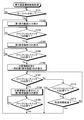
- FIG. 6 is a flowchart showing the display screen transition control processing procedure of the standard screen by the display control unit 33.
- the key switch SW is turned on (Yes in step S ⁇ b> 101)
- the first display screen V ⁇ b> 1 on which the image captured by the camera 9 is displayed on the left side of the display unit 31 is the initial standard.
- a screen is displayed on the display unit 31 (step S102).
- step S103 a third display screen V3 in which the video imaged by the camera 9 is displayed in the video display area M2 on the entire surface of the display unit 31 is displayed. It is displayed (step S104).
- Step S105 Yes
- the image captured by the camera 9 is hidden, and the engine A second display screen V2 in which the water temperature gauge G1, the hydraulic oil temperature gauge G2, and the fuel level gauge G3 are displayed on the entire surface of the display unit 31 is displayed, and further caution information D1 is displayed on the second display screen V2 ( Step S106).
- the attention information D1 includes an exclamation mark and a message “Please display the camera video before driving”.
- the attention information D1 is displayed on the second display screen V2.
- the temporary second display screen V2a displays the second display screen V2. Instead, only the attention information D1 may be displayed. That is, it is only necessary that at least the attention information D1 is displayed on the temporary second display screen V2a.
- the message in the caution information D1 is not limited to before traveling, but may include a content indicating that the video display is prompted before the turning operation or the work implement operation. Furthermore, the caution information D1 may be content that prompts video display, and is not limited to character display but may be audio output.
- an icon including a check mark is displayed as the guidance icon I25 corresponding to the function switch F5. Therefore, in the temporary second display screen V2a, the function switch F5 functions as a confirmation switch for the attention information D1.
- the caution information D1 and the guidance icon I25 perform highlighting such as painting with a yellow background or the like.
- step S107, Yes the function switch F5 which is a confirmation switch
- step S107, Yes the second display in which the caution information D1 and the guidance icon I25 are not displayed.
- the screen V2 is displayed (step S108).
- step S109, Yes the function switch F3 which is a screen changeover switch, is pressed while the second display screen V2 is displayed (step S109, Yes)
- step S102 the process proceeds to step S102 to display the first display screen V1, Repeat the process.
- step S107 when the function switch F5, which is a confirmation switch, is not pressed while the temporary second display screen V2a is displayed (step S107, No), and when the function switch F3, which is a screen switch, is further pressed (step S107). (S110, Yes), the process proceeds to step S102, the first display screen V1 is displayed, and the above-described processing is repeated.
- step S110, No when the function switch F3 that is the screen changeover switch is not pressed (step S110, No), whether or not a predetermined time, for example, 10 seconds has elapsed since the temporary second display screen V2a is displayed. Judgment is made (step S111).
- step S111, Yes When the predetermined time has elapsed (step S111, Yes), the process proceeds to step S102 and the first display screen V1 is displayed. On the other hand, when the predetermined time has not elapsed (step S111, No), the process proceeds to step S107, and the above-described processing is repeated. It should be noted that in the determination process of steps S101, S103, S105, and S109, if the determination is No, the determination process of steps S101, S103, S105, and S109 is repeated.
- the display transitions from the display of the first display screen V1 to the display of the third display screen V3 to the display of the temporary second display screen V2a.
- the transition from the display of the first display screen V1 to the display of the second display screen V2 is made, the transition is made via the temporary second display screen V2a.
- the first display screen V1 having the video display area cannot be directly shifted to the display of the second display screen V2 having no video display area.
- the caution information D1 or the like is displayed on the temporary second display screen V2a, it is possible to reliably recognize the backward confirmation before traveling.
- the temporary second display screen V2a is a screen display of only the attention information D1, it is possible to reliably recognize the backward confirmation.
- the display of the third display screen V3 and the display of the temporary second display screen V2a described above are performed by confirming the rear or side of the vehicle before or during traveling by causing a troublesome switch operation. It is possible to raise awareness.
- the operator forcibly performs not only visual observation but also backward confirmation and side confirmation by transitioning to the first display screen V1 with the video display area. You can run or work while.
- the caution information D1 is periodically thereafter displayed. May be repeatedly displayed on the second display screen V2. In this case, it is preferable that the repetitive display cycle of the caution information D1 is set so as not to hinder travel and work.
- the temporary second display screen V2a is for displaying the caution information D1 on the second display screen V2, or when the temporary second display screen V2a is for displaying only the caution information D1.
- the caution information D1 may be periodically and repeatedly displayed.
Landscapes
- Engineering & Computer Science (AREA)
- Multimedia (AREA)
- General Engineering & Computer Science (AREA)
- Structural Engineering (AREA)
- Civil Engineering (AREA)
- Mining & Mineral Resources (AREA)
- Mechanical Engineering (AREA)
- Theoretical Computer Science (AREA)
- Signal Processing (AREA)
- Human Computer Interaction (AREA)
- Physics & Mathematics (AREA)
- General Physics & Mathematics (AREA)
- Component Parts Of Construction Machinery (AREA)
- Closed-Circuit Television Systems (AREA)
- Instrument Panels (AREA)
Abstract
Description
図1は、この発明の実施の形態である作業車両の表示装置を搭載した作業車両の全体構成を示す斜視図である。この作業車両は、作業車両の一例として示した油圧ショベル1である。油圧ショベル1は、履帯等を有する下部走行体2と、下部走行体2の上部に旋回可能に装着される上部旋回体3と、上部旋回体3に結合される作業機4とを備える。作業機4は、その基部が上部旋回体3に動作可能に連結されているブーム5と、ブーム5の先端に動作可能に連結されているアーム6と、アーム6の先端に動作可能に連結されているバケット7とを備える。また、上部旋回体3は、運転室8等を備える。さらに、上部旋回体3の後部、例えばカウンタウエイトの上部には、油圧ショベル1の後方を撮像するカメラ9を備える。カメラ9は、油圧ショベル1の運転室8に搭乗したオペレータによる視認が悪い領域、例えば油圧ショベル1の後方領域を撮像する撮像部である。なお、カメラ9の設置位置や設置個数は、必要に応じて任意に選択することができる。また、運転室8の後部のエンジンルームには、エンジンの排気ガスに含まれる粒子状物質(PM:Particulate Matter)を除去する粒子状物質除去フィルタ(DPFと称される。DPF:Diesel Particulate Filter)や、排気ガス中の窒素酸化物を触媒還元する尿素SCR(Selective Catalytic Reduction)装置などの後処理装置が設けられている。このため、エンジンルームの容積が大きくなり、エンジンルームの高さが増し、オペレータによる後部の視認が悪くなる。しかし、オペレータは、上述したカメラ9によって撮像された後部あるいは側部の撮像画像によって、後部の視認低下を補うことができる。
図2は、運転室8の内部の構成を示す斜視図である。運転室8は、図2に示すように、その中央部に運転席10が設けられる。運転席10の前方に走行レバー11,12と、各走行レバー11,12と一体に動作する走行ペダル13,14とを備える。オペレータが走行レバー11,12を前方に押すと下部走行体2が前進する一方、オペレータが走行レバー11,12を後方に引くと下部走行体2が後進する。走行ペダル13,14の近傍には、アタッチメント用ペダル15が設けられている。また、図2の右方の側方窓16の近傍には、計器盤17が設けられている。
図3は、表示装置21の機能構成および表示装置21を中心とした制御システムの要部の構成を示すブロック図である。表示装置21は、オペレータやサービスマンなどの油圧ショベル操作者によって各種の指示または情報が入力される入力部32と、液晶画面等を用いて実現され、油圧ショベル1の動作に関する情報を含む各種情報を表示する表示部31と、CPU等を用いて実現され、表示装置21の表示部31に表示される画面の状態等を制御する表示制御部33と、を有する。
図4は、表示装置21の外観構成を示す図である。図4に示すように、入力部32は複数のスイッチによって構成されている。入力部32のうち、表示部31の下方に位置し、「F1」~「F6」とそれぞれ表示されているファンクションスイッチF1~F6は、各スイッチの上方で表示部31が表示するアイコンに対応した信号を入力するためのスイッチである。ファンクションスイッチF1~F6の下方には、作業機レバー18,19が中立位置に戻った際にエンジン回転数を所定の回転数まで低下させるオートデセル制御を実行させるオートデセルスイッチ211、油圧ショベル1の作業モードを複数の作業モードから選択する作業モード選択スイッチ212、油圧ショベル1の走行速度段を複数の走行速度段から選択する走行速度段選択スイッチ213、油圧ショベル1が所定の警告状態になると発生するブザー音をキャンセルするブザーキャンセルスイッチ214、運転室8のフロントガラスに設けられるワイパ(図示せず)を動作させるワイパスイッチ215、フロントガラスへ洗浄水を噴射するウォッシャ(図示せず)を作動するウォッシャスイッチ216、および運転室8内のエアコンの各種機能を操作するエアコンスイッチ217が設けられている。なお、入力部32として、抵抗膜方式等のタッチパネルを適用することも可能である。また、入力部32は、表示部31と別体で構成してもよい。この場合、例えば、入力部32は計器盤17に配置してもよい。
図5は、標準画面の表示画面遷移を示す状態遷移図である。また、図6は、表示制御部33による標準画面の表示画面遷移制御処理手順を示すフローチャートである。図5及び図6に示すように、キースイッチSWがキーオンされる(ステップS101,Yes)と、表示部31の左側にカメラ9によって撮像された映像が表示される第1表示画面V1が初期標準画面として表示部31に表示される(ステップS102)。その後、画面切替スイッチであるファンクションスイッチF3が押下される(ステップS103,Yes)と、表示部31の全面の映像表示領域M2にカメラ9によって撮像された映像が表示される第3表示画面V3が表示される(ステップS104)。
2 下部走行体
3 上部旋回体
4 作業機
5 ブーム
5a ブームシリンダ
6 アーム
6a アームシリンダ
7 バケット
7a バケットシリンダ
8 運転室
9 カメラ
10 運転席
11,12 走行レバー
13,14 走行ペダル
15 アタッチメント用ペダル
16 側方窓
17 計器盤
18,19 作業機レバー
20 ロックレバー
21 表示装置
22 前方窓
23 縦枠
31 表示部
32 入力部
33 表示制御部
34 警報ブザー
35 センサ
211 オートデセルスイッチ
212 作業モード選択スイッチ
213 走行速度段選択スイッチ
214 ブザーキャンセルスイッチ
215 ワイパスイッチ
216 ウォッシャスイッチ
217 エアコンスイッチ
C ポンプコントローラ
CN 車内ネットワーク
D1 注意情報
E1 サービスメータ/時計表示領域
E2 燃費計表示領域
F1~F6 ファンクションスイッチ
G1 エンジン水温ゲージ
G2 作動油温ゲージ
G3 燃料レベルゲージ
G4 尿素水レベルゲージ
G5 燃料消費ゲージ
I1~I11 アイコン
I21~I26 ガイダンスアイコン
M1,M2 映像表示領域
SW キースイッチ
V1 第1表示画面
V2 第2表示画面
V2a 一時的第2表示画面
V3 第3表示画面
Claims (15)
- 映像表示領域を含む第1表示画面と映像表示領域を含まない第2表示画面とを含む複数の表示画面を画面切替スイッチの操作によって順次切替表示することができる作業車両の表示装置であって、
前記第1表示画面から前記第2表示画面に切替表示する場合、前記第1表示画面への切替表示を促す注意情報を表示した一時的第2表示画面を表示することを特徴とする作業車両の表示装置。 - 前記一時的第2表示画面は、前記第2表示画面上に前記第1表示画面への切替表示を促す注意情報を表示したものであることを特徴とする請求項1に記載の作業車両の表示装置。
- 前記第1表示画面から前記第2表示画面に切替表示する場合、前記一時的第2表示画面を表示するとともに、前記一時的第2表示画面の表示後、所定時間経過した場合に前記第1表示画面に自動切替表示することを特徴とする請求項1または2に記載の作業車両の表示装置。
- 前記一時的第2表示画面を表示した状態で、該注意情報の確認スイッチが押下された場合、該注意情報を消去した前記第2表示画面を表示することを特徴とする請求項1~3のいずれか一つに記載の作業車両の表示装置。
- 前記一時的第2表示画面を表示した状態で、画面切替スイッチが押下された場合、前記第1表示画面を表示することを特徴とする請求項1~4のいずれか一つに記載の作業車両の表示装置。
- 前記第1表示画面から前記一時的第2表示画面に遷移する際、前記画面切替スイッチの押下によって前記第1表示画面から前記映像表示領域を全面表示する第3表示画面に遷移し、さらに画面切替スイッチの押下によって前記第3表示画面から前記一時的第2表示画面に遷移することを特徴とする請求項1~5のいずれか一つに記載の作業車両の表示装置。
- 前記第1表示画面は、キースイッチのキーオン後に表示される初期標準表示画面であることを特徴とする請求項1~6のいずれか一つに記載の作業車両の表示装置。
- 映像表示領域を含む第1表示画面と映像表示領域を含まない第2表示画面とを含む複数の表示画面を画面切替スイッチの操作によって順次切替表示することができる作業車両の表示装置であって、
前記第1表示画面から前記第2表示画面に遷移する際、前記画面切替スイッチの押下によって前記第1表示画面から前記映像表示領域を全面表示する第3表示画面に遷移し、
さらに、前記第3表示画面を表示した状態で画面切替スイッチを押下することによって、前記第3表示画面から、前記第2表示画面上に前記第1表示画面への切替表示を促す注意情報を表示した一時的第2表示画面に遷移し、
前記一時的第2表示画面を表示した状態で、前記注意情報の確認スイッチが押下された場合、該注意情報を消去した前記第2表示画面を表示し、
前記一時的第2表示画面を表示した状態で、画面切替スイッチが押下された場合、前記第1表示画面を表示することを特徴とする作業車両の表示装置。 - 映像表示領域を含む第1表示画面と映像表示領域を含まない第2表示画面とを含む複数の表示画面を画面切替スイッチの操作によって順次切替表示することができる作業車両の表示装置の表示方法であって、
前記第1表示画面から前記第2表示画面に切替表示する場合、前記第1表示画面への切替表示を促す注意情報を表示した一時的第2表示画面を表示することを特徴とする作業車両の表示装置の表示方法。 - 前記一時的第2表示画面は、前記第2表示画面上に前記第1表示画面への切替表示を促す注意情報を表示したものであることを特徴とする請求項9に記載の作業車両の表示装置の表示方法。
- 前記第1表示画面から前記第2表示画面に切替表示する場合、前記一時的第2表示画面を表示するとともに、前記一時的第2表示画面の表示後、所定時間経過した場合に前記第1表示画面に自動切替表示することを特徴とする請求項9または10に記載の作業車両の表示装置の表示方法。
- 前記一時的第2表示画面を表示した状態で、該注意情報の確認スイッチが押下された場合、該注意情報を消去した前記第2表示画面を表示することを特徴とする請求項9~11のいずれか一つに記載の作業車両の表示装置の表示方法。
- 前記一時的第2表示画面を表示した状態で、画面切替スイッチが押下された場合、前記第1表示画面を表示することを特徴とする請求項9~12のいずれか一つに記載の作業車両の表示装置の表示方法。
- 前記第1表示画面から前記一時的第2表示画面に遷移する際、前記画面切替スイッチの押下によって前記第1表示画面から前記映像表示領域を全面表示する第3表示画面に遷移し、さらに画面切替スイッチの押下によって前記第3表示画面から前記一時的第2表示画面に遷移することを特徴とする請求項9~13のいずれか一つに記載の作業車両の表示装置の表示方法。
- 前記第1表示画面は、キースイッチのキーオン後に表示される初期標準表示画面であることを特徴とする請求項9~14のいずれか一つに記載の作業車両の表示装置の表示方法。
Priority Applications (6)
| Application Number | Priority Date | Filing Date | Title |
|---|---|---|---|
| JP2013557306A JP5572770B1 (ja) | 2013-11-19 | 2013-11-19 | 作業車両の表示装置及びその表示方法 |
| KR1020157005817A KR101691317B1 (ko) | 2013-11-19 | 2013-11-19 | 작업 차량의 표시 장치 및 그 표시 방법 |
| CN201380003015.7A CN104797463B (zh) | 2013-11-19 | 2013-11-19 | 作业车辆的显示装置及其显示方法 |
| PCT/JP2013/081217 WO2015025439A1 (ja) | 2013-11-19 | 2013-11-19 | 作業車両の表示装置及びその表示方法 |
| US14/344,147 US9587380B2 (en) | 2013-11-19 | 2013-11-19 | Display device of work vehicle and display method for the same |
| DE112013000197.7T DE112013000197B4 (de) | 2013-11-19 | 2013-11-19 | Anzeigegerät eines Arbeitsfahrzeugs und Anzeigeverfahren dafür |
Applications Claiming Priority (1)
| Application Number | Priority Date | Filing Date | Title |
|---|---|---|---|
| PCT/JP2013/081217 WO2015025439A1 (ja) | 2013-11-19 | 2013-11-19 | 作業車両の表示装置及びその表示方法 |
Publications (1)
| Publication Number | Publication Date |
|---|---|
| WO2015025439A1 true WO2015025439A1 (ja) | 2015-02-26 |
Family
ID=51427317
Family Applications (1)
| Application Number | Title | Priority Date | Filing Date |
|---|---|---|---|
| PCT/JP2013/081217 Ceased WO2015025439A1 (ja) | 2013-11-19 | 2013-11-19 | 作業車両の表示装置及びその表示方法 |
Country Status (6)
| Country | Link |
|---|---|
| US (1) | US9587380B2 (ja) |
| JP (1) | JP5572770B1 (ja) |
| KR (1) | KR101691317B1 (ja) |
| CN (1) | CN104797463B (ja) |
| DE (1) | DE112013000197B4 (ja) |
| WO (1) | WO2015025439A1 (ja) |
Cited By (6)
| Publication number | Priority date | Publication date | Assignee | Title |
|---|---|---|---|---|
| DE102015212223B3 (de) * | 2015-06-30 | 2016-08-11 | Continental Automotive Gmbh | Verfahren zur Ansteuerung eines Anzeigegeräts für ein Fahrzeug |
| JPWO2017047654A1 (ja) * | 2015-09-15 | 2018-06-28 | 住友建機株式会社 | ショベル |
| WO2020080293A1 (ja) * | 2018-10-15 | 2020-04-23 | 日立建機株式会社 | 油圧ショベル |
| JP2023183700A (ja) * | 2022-06-16 | 2023-12-28 | ヤンマーホールディングス株式会社 | 作業機械の制御方法、作業機械用制御プログラム、作業機械用制御システム及び作業機械 |
| JP2023183699A (ja) * | 2022-06-16 | 2023-12-28 | ヤンマーホールディングス株式会社 | 作業機械の制御方法、作業機械用制御プログラム、作業機械用制御システム及び作業機械 |
| JP2025000834A (ja) * | 2020-10-12 | 2025-01-07 | ヤンマーホールディングス株式会社 | 作業車両の制御方法 |
Families Citing this family (19)
| Publication number | Priority date | Publication date | Assignee | Title |
|---|---|---|---|---|
| JP6675975B2 (ja) * | 2014-04-25 | 2020-04-08 | 住友建機株式会社 | 建設機械及び建設機械の制御方法 |
| EP3021178B1 (en) * | 2014-11-14 | 2020-02-19 | Caterpillar Inc. | System using radar apparatus for assisting a user of a machine of a kind comprising a body and an implement |
| EP3020868B1 (en) * | 2014-11-14 | 2020-11-04 | Caterpillar Inc. | Machine of a kind comprising a body and an implement movable relative to the body with a system for assisting a user of the machine |
| JPWO2016174754A1 (ja) * | 2015-04-28 | 2018-02-15 | 株式会社小松製作所 | 作業機械の周辺監視装置及び作業機械の周辺監視方法 |
| JP6672313B2 (ja) * | 2015-08-10 | 2020-03-25 | 住友建機株式会社 | ショベル |
| DE102015222795A1 (de) * | 2015-11-18 | 2017-05-18 | Bayerische Motoren Werke Aktiengesellschaft | Anzeigeeinheit zum Anzeigen einer Restreichweite in einem Kraftfahrzeug |
| JP6761102B2 (ja) * | 2017-02-22 | 2020-09-23 | 住友建機株式会社 | ショベル |
| JP6739375B2 (ja) * | 2017-03-03 | 2020-08-12 | ヤンマーパワーテクノロジー株式会社 | 無線通信装置 |
| JP6714906B2 (ja) * | 2018-06-25 | 2020-07-01 | コベルコ建機株式会社 | 建設機械のワイパー操作システム |
| CN109353277A (zh) * | 2018-09-29 | 2019-02-19 | 深圳创维汽车智能有限公司 | 车辆盲区监测方法、装置及计算机可读存储介质 |
| JP7797092B2 (ja) | 2019-09-13 | 2026-01-13 | 株式会社小松製作所 | 作業機械の表示システムおよび作業機械の表示方法 |
| WO2021085608A1 (ja) * | 2019-10-31 | 2021-05-06 | 住友建機株式会社 | ショベル管理システム、ショベル用携帯端末、およびショベル用携帯端末に用いられるプログラム |
| WO2021178815A1 (en) * | 2020-03-06 | 2021-09-10 | Oshkosh Corporation | Systems and methods for augmented reality application |
| JP7605599B2 (ja) * | 2020-08-11 | 2024-12-24 | ヤンマーホールディングス株式会社 | 表示装置、及びそれを備える作業機械 |
| JP7438999B2 (ja) * | 2021-02-12 | 2024-02-27 | ヤンマーホールディングス株式会社 | 作業機械用表示制御システム、作業機械用表示システム、作業機械、作業機械用表示制御方法及び作業機械用表示制御プログラム |
| JP7414041B2 (ja) * | 2021-07-13 | 2024-01-16 | コベルコ建機株式会社 | 実機診断システム、実機診断複合システムおよび実機診断方法 |
| US11781463B2 (en) * | 2022-01-31 | 2023-10-10 | Kubota Corporation | Work vehicle including DPF |
| US20230272599A1 (en) * | 2022-02-28 | 2023-08-31 | Caterpillar Inc. | Work machine safety zone control |
| US12227145B2 (en) * | 2023-01-20 | 2025-02-18 | Caterpillar Inc. | Machine security system |
Citations (2)
| Publication number | Priority date | Publication date | Assignee | Title |
|---|---|---|---|---|
| WO2007018021A1 (ja) * | 2005-08-05 | 2007-02-15 | Komatsu Ltd. | 作業用車両に搭載される表示装置、及び同表示装置の表示方法 |
| US20100091103A1 (en) * | 2007-04-18 | 2010-04-15 | Metso Minerals Inc. | User interface of mineral material processing equipment |
Family Cites Families (25)
| Publication number | Priority date | Publication date | Assignee | Title |
|---|---|---|---|---|
| AU774006B2 (en) * | 1999-03-17 | 2004-06-10 | Komatsu Limited | Communication device of mobile unit |
| JP4243007B2 (ja) * | 2000-06-09 | 2009-03-25 | 矢崎総業株式会社 | 表示機能付多機能スイッチ装置 |
| JP2002275949A (ja) * | 2001-03-14 | 2002-09-25 | Hitachi Constr Mach Co Ltd | 建設機械の情報表示装置及び表示制御装置 |
| JP2002293164A (ja) * | 2001-04-02 | 2002-10-09 | Sumitomo (Shi) Construction Machinery Manufacturing Co Ltd | 土木・建設機械の表示装置 |
| US9146585B2 (en) * | 2010-10-01 | 2015-09-29 | Z124 | Dual-screen view in response to rotation |
| JP3952199B2 (ja) | 2003-10-14 | 2007-08-01 | 大阪ベビー&シルバー用品協同組合 | 歩行補助車 |
| JP2005163370A (ja) * | 2003-12-02 | 2005-06-23 | Hitachi Constr Mach Co Ltd | 建設機械の画像表示装置 |
| JP4332028B2 (ja) * | 2003-12-25 | 2009-09-16 | キャタピラージャパン株式会社 | 表示器制御システム |
| JP4399730B2 (ja) * | 2004-09-30 | 2010-01-20 | マツダ株式会社 | 車両用情報表示装置 |
| JP5011141B2 (ja) * | 2008-01-30 | 2012-08-29 | 日立建機株式会社 | 異常動作検知装置 |
| US8392075B2 (en) * | 2008-02-25 | 2013-03-05 | Clark Equipment Company | Carrier and backhoe control system and method |
| WO2011074672A1 (ja) * | 2009-12-18 | 2011-06-23 | 株式会社小松製作所 | 作業車両のモニタ装置 |
| KR20110077063A (ko) * | 2009-12-30 | 2011-07-07 | 볼보 컨스트럭션 이큅먼트 에이비 | 건설기계의 카메라모드 제어방법 |
| JP5367665B2 (ja) * | 2010-09-17 | 2013-12-11 | 日立建機株式会社 | 作業機械の表示システム |
| CN202918411U (zh) * | 2012-10-12 | 2013-05-01 | 广东丰诺汽车安全科技有限公司 | 一种信息显示系统 |
| US8773286B1 (en) * | 2013-02-08 | 2014-07-08 | Caterpillar Inc. | Operator assistance system |
| IN2015DN06419A (ja) * | 2013-07-22 | 2015-07-31 | Komatsu Mfg Co Ltd | |
| CN104024610B (zh) * | 2013-09-19 | 2016-03-09 | 株式会社小松制作所 | 作业车辆 |
| KR101614673B1 (ko) * | 2013-11-26 | 2016-04-21 | 가부시키가이샤 고마쓰 세이사쿠쇼 | 작업 차량 |
| DE112014000009B3 (de) * | 2014-01-14 | 2015-03-26 | Komatsu Ltd. | Baufahrzeug |
| CN105008690B (zh) * | 2014-02-18 | 2018-06-12 | 株式会社小松制作所 | 作业车辆用显示装置和作业车辆 |
| WO2014185117A1 (ja) * | 2014-02-26 | 2014-11-20 | 株式会社小松製作所 | 作業車両 |
| JP5876572B2 (ja) * | 2014-02-28 | 2016-03-02 | 株式会社小松製作所 | 作業車両のエラー解除装置及び作業車両のエラー解除方法 |
| JP5702033B1 (ja) * | 2014-05-16 | 2015-04-15 | 株式会社小松製作所 | 作業車両および作業車両の制御方法 |
| EP3654163B1 (en) * | 2014-05-30 | 2023-12-13 | Apple Inc. | Transition from use of one device to another |
-
2013
- 2013-11-19 KR KR1020157005817A patent/KR101691317B1/ko active Active
- 2013-11-19 CN CN201380003015.7A patent/CN104797463B/zh active Active
- 2013-11-19 DE DE112013000197.7T patent/DE112013000197B4/de active Active
- 2013-11-19 US US14/344,147 patent/US9587380B2/en active Active
- 2013-11-19 JP JP2013557306A patent/JP5572770B1/ja active Active
- 2013-11-19 WO PCT/JP2013/081217 patent/WO2015025439A1/ja not_active Ceased
Patent Citations (2)
| Publication number | Priority date | Publication date | Assignee | Title |
|---|---|---|---|---|
| WO2007018021A1 (ja) * | 2005-08-05 | 2007-02-15 | Komatsu Ltd. | 作業用車両に搭載される表示装置、及び同表示装置の表示方法 |
| US20100091103A1 (en) * | 2007-04-18 | 2010-04-15 | Metso Minerals Inc. | User interface of mineral material processing equipment |
Cited By (10)
| Publication number | Priority date | Publication date | Assignee | Title |
|---|---|---|---|---|
| DE102015212223B3 (de) * | 2015-06-30 | 2016-08-11 | Continental Automotive Gmbh | Verfahren zur Ansteuerung eines Anzeigegeräts für ein Fahrzeug |
| US10102826B2 (en) | 2015-06-30 | 2018-10-16 | Continental Automotive Gmbh | Method for operating a display device for a vehicle |
| JPWO2017047654A1 (ja) * | 2015-09-15 | 2018-06-28 | 住友建機株式会社 | ショベル |
| US10927528B2 (en) | 2015-09-15 | 2021-02-23 | Sumitomo(S.H.I.) Construction Machinery Co., Ltd. | Shovel |
| WO2020080293A1 (ja) * | 2018-10-15 | 2020-04-23 | 日立建機株式会社 | 油圧ショベル |
| US11739503B2 (en) | 2018-10-15 | 2023-08-29 | Hitachi Construction Machinery Co., Ltd. | Hydraulic excavator |
| JP2025000834A (ja) * | 2020-10-12 | 2025-01-07 | ヤンマーホールディングス株式会社 | 作業車両の制御方法 |
| JP7855656B2 (ja) | 2020-10-12 | 2026-05-08 | ヤンマーホールディングス株式会社 | 作業車両の制御方法 |
| JP2023183700A (ja) * | 2022-06-16 | 2023-12-28 | ヤンマーホールディングス株式会社 | 作業機械の制御方法、作業機械用制御プログラム、作業機械用制御システム及び作業機械 |
| JP2023183699A (ja) * | 2022-06-16 | 2023-12-28 | ヤンマーホールディングス株式会社 | 作業機械の制御方法、作業機械用制御プログラム、作業機械用制御システム及び作業機械 |
Also Published As
| Publication number | Publication date |
|---|---|
| DE112013000197T5 (de) | 2015-08-20 |
| US20160258134A1 (en) | 2016-09-08 |
| KR20150058186A (ko) | 2015-05-28 |
| JPWO2015025439A1 (ja) | 2017-03-02 |
| JP5572770B1 (ja) | 2014-08-13 |
| DE112013000197B4 (de) | 2016-10-27 |
| KR101691317B1 (ko) | 2017-01-09 |
| US9587380B2 (en) | 2017-03-07 |
| CN104797463A (zh) | 2015-07-22 |
| CN104797463B (zh) | 2017-03-15 |
Similar Documents
| Publication | Publication Date | Title |
|---|---|---|
| JP5572770B1 (ja) | 作業車両の表示装置及びその表示方法 | |
| JP6067858B2 (ja) | 作業機械の状態情報表示装置、作業機械の警告表示方法、及び作業機械の警告表示プログラム | |
| US20150081165A1 (en) | Construction Machine and Method for Reporting Quality of Driving Operations of Construction Machine | |
| US8972124B2 (en) | Work vehicle | |
| US8959893B2 (en) | Guidance output device, guidance output method, and construction machine equipped with guidance output device | |
| JP5685679B1 (ja) | 作業車両 | |
| US20160265196A1 (en) | Display device of working vehicle, display method of the same, and working vehicle | |
| JP7842141B2 (ja) | 作業機械の制御方法 | |
| KR20150089089A (ko) | 작업 차량 | |
| CN104411935A (zh) | 作业车辆 | |
| JP2018204252A (ja) | 建設機械 | |
| JPWO2018123001A1 (ja) | 作業車両および作業車両の制御システム | |
| CN116323317A (zh) | 作业车辆 | |
| CN1621628B (zh) | 工程建筑机械的显示装置 | |
| JP6403332B2 (ja) | 作業車両 | |
| JP4812613B2 (ja) | ホイール式作業機械 | |
| CN105026655A (zh) | 轮式作业车辆的状态信息显示装置、轮式作业车辆的维护用画面的显示方法、以及轮式作业车辆的维护用画面显示程序 | |
| JP2012172360A (ja) | ホイール式作業機械 | |
| JP5536141B2 (ja) | 建設機械、及び建設機械の運転動作の良否報知方法 | |
| WO2026070464A1 (ja) | 表示制御装置および表示制御方法 |
Legal Events
| Date | Code | Title | Description |
|---|---|---|---|
| ENP | Entry into the national phase |
Ref document number: 2013557306 Country of ref document: JP Kind code of ref document: A |
|
| WWE | Wipo information: entry into national phase |
Ref document number: 14344147 Country of ref document: US |
|
| WWE | Wipo information: entry into national phase |
Ref document number: 112013000197 Country of ref document: DE Ref document number: 1120130001977 Country of ref document: DE |
|
| ENP | Entry into the national phase |
Ref document number: 20157005817 Country of ref document: KR Kind code of ref document: A |
|
| 121 | Ep: the epo has been informed by wipo that ep was designated in this application |
Ref document number: 13891729 Country of ref document: EP Kind code of ref document: A1 |
|
| 122 | Ep: pct application non-entry in european phase |
Ref document number: 13891729 Country of ref document: EP Kind code of ref document: A1 |