WO2015016337A1 - 点火プラグ及びプラズマ発生装置 - Google Patents
点火プラグ及びプラズマ発生装置 Download PDFInfo
- Publication number
- WO2015016337A1 WO2015016337A1 PCT/JP2014/070307 JP2014070307W WO2015016337A1 WO 2015016337 A1 WO2015016337 A1 WO 2015016337A1 JP 2014070307 W JP2014070307 W JP 2014070307W WO 2015016337 A1 WO2015016337 A1 WO 2015016337A1
- Authority
- WO
- WIPO (PCT)
- Prior art keywords
- electrode
- tip
- spark plug
- discharge
- spark
- Prior art date
Links
Images


Classifications
-
- F—MECHANICAL ENGINEERING; LIGHTING; HEATING; WEAPONS; BLASTING
- F02—COMBUSTION ENGINES; HOT-GAS OR COMBUSTION-PRODUCT ENGINE PLANTS
- F02P—IGNITION, OTHER THAN COMPRESSION IGNITION, FOR INTERNAL-COMBUSTION ENGINES; TESTING OF IGNITION TIMING IN COMPRESSION-IGNITION ENGINES
- F02P9/00—Electric spark ignition control, not otherwise provided for
- F02P9/002—Control of spark intensity, intensifying, lengthening, suppression
- F02P9/007—Control of spark intensity, intensifying, lengthening, suppression by supplementary electrical discharge in the pre-ionised electrode interspace of the sparking plug, e.g. plasma jet ignition
-
- F—MECHANICAL ENGINEERING; LIGHTING; HEATING; WEAPONS; BLASTING
- F02—COMBUSTION ENGINES; HOT-GAS OR COMBUSTION-PRODUCT ENGINE PLANTS
- F02P—IGNITION, OTHER THAN COMPRESSION IGNITION, FOR INTERNAL-COMBUSTION ENGINES; TESTING OF IGNITION TIMING IN COMPRESSION-IGNITION ENGINES
- F02P3/00—Other installations
- F02P3/01—Electric spark ignition installations without subsequent energy storage, i.e. energy supplied by an electrical oscillator
-
- H—ELECTRICITY
- H01—ELECTRIC ELEMENTS
- H01T—SPARK GAPS; OVERVOLTAGE ARRESTERS USING SPARK GAPS; SPARKING PLUGS; CORONA DEVICES; GENERATING IONS TO BE INTRODUCED INTO NON-ENCLOSED GASES
- H01T13/00—Sparking plugs
- H01T13/02—Details
- H01T13/04—Means providing electrical connection to sparking plugs
-
- H—ELECTRICITY
- H01—ELECTRIC ELEMENTS
- H01T—SPARK GAPS; OVERVOLTAGE ARRESTERS USING SPARK GAPS; SPARKING PLUGS; CORONA DEVICES; GENERATING IONS TO BE INTRODUCED INTO NON-ENCLOSED GASES
- H01T13/00—Sparking plugs
- H01T13/20—Sparking plugs characterised by features of the electrodes or insulation
-
- H—ELECTRICITY
- H01—ELECTRIC ELEMENTS
- H01T—SPARK GAPS; OVERVOLTAGE ARRESTERS USING SPARK GAPS; SPARKING PLUGS; CORONA DEVICES; GENERATING IONS TO BE INTRODUCED INTO NON-ENCLOSED GASES
- H01T13/00—Sparking plugs
- H01T13/40—Sparking plugs structurally combined with other devices
-
- H—ELECTRICITY
- H05—ELECTRIC TECHNIQUES NOT OTHERWISE PROVIDED FOR
- H05H—PLASMA TECHNIQUE; PRODUCTION OF ACCELERATED ELECTRICALLY-CHARGED PARTICLES OR OF NEUTRONS; PRODUCTION OR ACCELERATION OF NEUTRAL MOLECULAR OR ATOMIC BEAMS
- H05H1/00—Generating plasma; Handling plasma
- H05H1/24—Generating plasma
- H05H1/46—Generating plasma using applied electromagnetic fields, e.g. high frequency or microwave energy
-
- H—ELECTRICITY
- H05—ELECTRIC TECHNIQUES NOT OTHERWISE PROVIDED FOR
- H05H—PLASMA TECHNIQUE; PRODUCTION OF ACCELERATED ELECTRICALLY-CHARGED PARTICLES OR OF NEUTRONS; PRODUCTION OR ACCELERATION OF NEUTRAL MOLECULAR OR ATOMIC BEAMS
- H05H1/00—Generating plasma; Handling plasma
- H05H1/24—Generating plasma
- H05H1/52—Generating plasma using exploding wires or spark gaps
-
- F—MECHANICAL ENGINEERING; LIGHTING; HEATING; WEAPONS; BLASTING
- F02—COMBUSTION ENGINES; HOT-GAS OR COMBUSTION-PRODUCT ENGINE PLANTS
- F02P—IGNITION, OTHER THAN COMPRESSION IGNITION, FOR INTERNAL-COMBUSTION ENGINES; TESTING OF IGNITION TIMING IN COMPRESSION-IGNITION ENGINES
- F02P23/00—Other ignition
- F02P23/04—Other physical ignition means, e.g. using laser rays
- F02P23/045—Other physical ignition means, e.g. using laser rays using electromagnetic microwaves
-
- F—MECHANICAL ENGINEERING; LIGHTING; HEATING; WEAPONS; BLASTING
- F02—COMBUSTION ENGINES; HOT-GAS OR COMBUSTION-PRODUCT ENGINE PLANTS
- F02P—IGNITION, OTHER THAN COMPRESSION IGNITION, FOR INTERNAL-COMBUSTION ENGINES; TESTING OF IGNITION TIMING IN COMPRESSION-IGNITION ENGINES
- F02P3/00—Other installations
- F02P3/02—Other installations having inductive energy storage, e.g. arrangements of induction coils
Definitions
- the present invention relates to a spark plug and a plasma generator in which a pulse voltage for spark discharge and an electromagnetic wave supplied as energy to the spark discharge are fed to a center electrode.
- a plasma generating apparatus that creates local plasma using spark plug discharge and expands this plasma using electromagnetic waves (for example, see Patent Document 1).
- This plasma generator is provided with a mixing circuit that mixes the discharge current for spark discharge (energy for discharge) and the energy of the electromagnetic wave from the electromagnetic wave generator, and this mixing circuit is input to the spark plug. It is connected to the connection terminal part which becomes a terminal. Thereby, the high voltage pulse (discharge current) for spark discharge and the electromagnetic wave are fed to the spark plug through the same transmission line (electric circuit). Therefore, the center electrode of the spark plug serves as both a spark discharge electrode and an electromagnetic wave radiation antenna.
- the center electrode of a general spark plug used in this plasma generator (hereinafter collectively referred to as the center electrode from the terminal portion connected to the ignition coil to the tip portion forming the discharge gap between the ground electrode)
- the center electrode from the terminal portion connected to the ignition coil to the tip portion forming the discharge gap between the ground electrode) (hereinafter collectively referred to as the center electrode from the terminal portion connected to the ignition coil to the tip portion forming the discharge gap between the ground electrode)
- the center electrode from the terminal portion connected to the ignition coil to the tip portion forming the discharge gap between the ground electrode) The same shall apply hereinafter
- the center electrode from the terminal portion connected to the ignition coil to the tip portion forming the discharge gap between the ground electrode is usually made of an iron-based alloy except for the tip.
- the electromagnetic wave supplied from the AC power source flows on the surface of the center electrode.
- the main component is iron with high permeability, it causes a large power loss, and the electromagnetic wave oscillator cannot be reduced in size. It was.
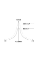
- the discharge current and electromagnetic waves for spark discharge are both radiated from the tip of the center electrode. Therefore, the electric field strength generated by the discharge current and the electromagnetic wave between the tip of the center electrode and the ground electrode is highest at the axial core portion of the center electrode.
- the electric field strength generated by the discharge current and electromagnetic waves between the tip of the center electrode and the ground electrode is such that the axis of the center electrode is symmetrical with respect to the axis of the center electrode.
- the highest curve is a curve that decreases toward the outer edge of the insulator covering the center electrode. For this reason, the electric field strength generated by the discharge current and the electromagnetic wave is superimposed, and the axial center of the center electrode has the highest temperature, and the tip end portion of the center electrode is easily melted.
- the present invention has been made based on the circumstances as described above, and the purpose of the present invention is to achieve the tip of the center electrode even when the discharge current and the electromagnetic wave are supplied from the terminal fitting portion of the spark plug. It is an object of the present invention to provide an ignition plug and a plasma generator using the ignition plug, in which a portion does not melt and the power loss of electromagnetic waves can be reduced.
- the first invention made to solve the above problems is A center electrode provided with a terminal metal part that receives power from the outside and an electrode main body electrically connected to the terminal metal part, An insulator having a shaft hole into which the center electrode is fitted; A metal shell arranged to surround the periphery of the insulator; A ground electrode extending from an end face of the metal shell and forming a discharge gap in which a spark discharge is generated between the electrode main body and the electrode body, An electromagnetic wave supplied as energy to a pulse voltage for spark discharge and spark discharge is a spark plug that is fed to the terminal fitting part,
- the electrode body portion is An electrode tip having an electrode tip for causing a spark discharge with the ground electrode; A cylindrical tip dielectric cylinder covering the electrode tip portion; It is a spark plug composed of a cylindrical connecting conductor tube that joins the tip dielectric tube and the terminal fitting part.
- the energy (discharge current) for spark discharge flows from the terminal fitting portion through the center portion of the electrode shaft core and is discharged from the tip of the electrode tip portion.
- the electromagnetic wave having the characteristic of flowing on the surface of the substance flows from the terminal fitting portion to the tip dielectric tube via the connecting conductor tube, and is radiated from the end surface of the tip dielectric tube on the ground electrode side. For this reason, the electric field strength due to the discharge current between the tip of the center electrode and the ground electrode is the highest in the axial center of the central electrode, but the electric field strength due to electromagnetic waves is outside the axial center of the central electrode (centering on the axial center).
- the highest temperature and the high temperature portion are not concentrated on the shaft core portion, and it is possible to effectively prevent melting of the tip portion of the center electrode. Further, as described above, electromagnetic waves can efficiently flow through the connecting conductor cylinder and the tip dielectric cylinder, and power loss can be minimized.
- the tip end surface of the electrode tip portion is configured such that the end surface on the ground electrode side of the tip dielectric tube is located substantially on the same plane or in the tip dielectric tube, so that the tip portion of the center electrode can be more reliably melted. Can be prevented.
- a center electrode provided with a terminal metal part that receives power from the outside and an electrode main body electrically connected to the terminal metal part, An insulator having a shaft hole into which the center electrode is fitted; A metal shell arranged to surround the periphery of the insulator; A ground electrode extending from an end face of the metal shell and forming a discharge gap in which a spark discharge is generated between the electrode main body and the electrode body, An electromagnetic wave supplied as energy to a pulse voltage for spark discharge and spark discharge is a spark plug that is fed to the terminal fitting part,
- the electrode body part is a connection conductor connected to the terminal metal part, A connecting conductor tube connected to the opposite terminal metal part of the connecting conductor; A tip dielectric cylinder fitted into the inner diameter side of the connecting conductor cylinder; The electrode tip portion is inserted into the tip dielectric tube, The connection conductor and the electrode tip are spark plugs connected via a resistor or a conductor.
- the spark plug of the second invention can be manufactured and assembled efficiently by unitizing the electrode body.
- the connection conductor and the electrode tip are connected via a resistor or conductor, and particularly when connecting via a resistor, the electromagnetic wave is generated even if a resistance for preventing electric spark plugs is provided inside. It efficiently flows on the surface of the connecting conductor and the tip dielectric tube, and is radiated from the tip surface of the tip dielectric tube with minimal power loss.
- the tip end surface of the electrode tip is configured so that the end surface on the ground electrode side of the tip dielectric tube is substantially on the same plane or in the tip dielectric tube. It is possible to more reliably prevent the portion from being melted.
- the resistor may be a resistor composition powder filled in the tip dielectric cylinder.
- Resistor composition powder composite powder material mixed with glass powder, metal powder and carbon powder
- the parts of the unitized electrode main body are sealed and fixed.
- the third invention made to solve the above problems is as follows: A center electrode provided with a terminal metal part that receives power from the outside and an electrode main body electrically connected to the terminal metal part, An insulator having a shaft hole into which the center electrode is fitted; A metal shell arranged to surround the periphery of the insulator; A ground electrode extending from an end face of the metal shell and forming a discharge gap in which a spark discharge is generated between the electrode main body and the electrode body, An electromagnetic wave supplied as energy to a pulse voltage for spark discharge and spark discharge is a spark plug that is fed to the terminal fitting part,
- the electrode main body part has a main center electrode extending from the end face center part of the terminal metal part, A rear end conductor tube that covers the main center electrode and is electrically connected to the terminal fitting, and one end is electrically connected to the rear end conductor tube, and the other end is from a front end conductor tube located near the ground electrode.
- the main center electrode is held via a cylindrical insulator at a connection portion between the rear end conductor tube and the front end conductor tube,
- the frequency of the electromagnetic wave to be supplied is ⁇
- the axial length of the annular gap between the tip conductor cylinder and the main center electrode is ⁇ / 4
- a spark plug in which an axial length of an annular gap between the rear end conductor tube and the main center electrode is ⁇ / 2.
- a spark plug in which an annular length between the front end conductor tube and the main center electrode is set to ⁇ / 4, and an annular gap between the rear end conductor tube and the main center electrode is set.
- the axial gap between the tip conductor cylinder and the main center electrode is made long by setting the axial length of the axis to ⁇ / 2 and the annular gap between the rear end conductor cylinder and the main center electrode having a virtual ground resonance structure.
- the resonance structure is ⁇ / 4 (hereinafter referred to as a tip resonance structure).
- the electromagnetic waves flowing on the surfaces of the rear end conductor cylinder and the front end conductor cylinder the electromagnetic waves flowing into the annular gap between the front end conductor cylinder and the main center electrode without being emitted from the open end surface of the front end conductor cylinder into the combustion chamber. Can be forcibly radiated into the combustion chamber by the tip resonance structure, and the electric field can be increased.
- the open end of the tip conductor tube can be expanded.
- the position where the electric field intensity due to the electromagnetic wave becomes the highest is generated in a ring shape at a position further away from the axial center of the center electrode, and it is possible to effectively prevent melting of the tip portion of the center electrode.
- a refractory metal can be disposed at the open end of the tip conductor tube. As a result, it is possible to effectively prevent melting of the open end of the tip conductor tube.
- the present invention also includes a plasma generation apparatus including the plasma generation apparatus.
- the plasma generator of the present invention is An ignition coil for supplying a discharge voltage; An electromagnetic wave oscillator that oscillates electromagnetic waves; A mixer for mixing energy for discharge and energy of electromagnetic waves;
- the spark plug is provided for introducing a pulse voltage for spark discharge and an electromagnetic wave supplied as energy to the spark discharge into a reaction region where a combustion reaction or a plasma reaction is performed.
- the plasma generator of the present invention can reduce the power loss of the electromagnetic wave (microwave) introduced into the reaction region by using the spark plug that can effectively prevent melting of the tip portion of the center electrode. it can.
- the spark plug can be used for a long time, and the electromagnetic wave oscillator can be miniaturized.
- a conductor is a metal material such as iron, silver, copper, gold, aluminum, tungsten, molybdenum, titanium, zirconium, niobium, tantalum, bismuth, lead, tin or An alloy mainly composed of these materials or a composite material thereof is referred to.
- a dielectric tip dielectric cylinder refers to a dielectric material, ceramics based on alumina (AL 2 O 3 ), or the like.
- the present invention even in the case of a spark plug configured to feed a discharge current and an electromagnetic wave from the terminal fitting portion of the spark plug, it is possible to effectively prevent melting of the tip portion of the center electrode and to provide a power loss of the supplied electromagnetic wave. Can be reduced. Further, in the plasma generator using the spark plug, the electromagnetic wave oscillator can be reduced in size, and the entire apparatus can be reduced in size and cost.
- the ignition plug which concerns on 1st Embodiment is shown, (a) is a partial cross section figure, (b) is the elements on larger scale of the example which divided
- the ignition plug which concerns on 2nd Embodiment is shown, (a) is partial sectional drawing, (b) is a partial expanded sectional view of an electrode main-body part. It is the schematic of the plasma generator which concerns on this invention. It is a graph which shows the electric field strength of the discharge current of the conventional spark plug, and the electric field strength of electromagnetic waves.
- the ignition plug which concerns on 3rd Embodiment is shown, (a) is partial sectional drawing, (b) is a partial expanded sectional view which shows the modification of a front-end
- -Spark plug- Embodiment 1 is a spark plug according to the present invention.
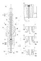
- FIG. 1 shows a spark plug according to the first embodiment.
- the spark plug 1 includes a center electrode 2 including a terminal metal part 2A that receives power from the outside and an electrode main body part 2B that is electrically connected to the terminal metal part 2A, and an electrode main body part 2B of the center electrode 2.
- a pulse voltage for the spark discharge and an electromagnetic wave supplied as energy to the spark discharge are fed to the terminal fitting 2A of the center electrode 2 Is done.
- the spark plug 1 includes a tip electrode 25 provided with an electrode tip portion 25a for causing the electrode body portion 2B to generate a spark discharge with the ground electrode 5, and a cylindrical tip covering the electrode tip portion 25a.
- the dielectric cylinder 24 and a cylindrical connecting conductor cylinder 23 that joins the distal dielectric cylinder 24 and the terminal fitting 2A, and the distal end face 25b of the electrode tip portion 25a is the ground electrode side end face 24a of the distal dielectric cylinder 24. Are located on the same plane or in the tip dielectric cylinder 24.
- the insulator 3 is formed by a known method, for example, an alumina powder is formed by a hydrostatic press with ceramics based on alumina (AL 2 O 3 ) having high insulation and heat and corrosion resistance, and is ground with a grindstone or the like. Thereafter, the insulator 3 is manufactured by baking at around 1600 ° C. In the shaft hole 30 into which the center electrode 2 is fitted, a stepped portion 30a is formed for locking an end portion of the connecting conductor tube 23 of the electrode main body 2B described later on the ground electrode 5 side.
- the positioning between the tip end face 25b of the electrode tip portion 25a and the ground electrode side end face 24a of the tip dielectric cylinder 24 is provided with a step portion having a small diameter on the tip side on the outer peripheral surface of the tip electrode 25 forming the electrode tip portion 25a, A step portion having a large diameter on the tip side is provided on the inner surface of the tip dielectric tube 24, and the step portion of the tip electrode 25 is engaged with the step portion of the tip dielectric tube 24.
- a noble metal for example, platinum alloy or iridium having a high melting point and oxidation resistance for the tip portion of the electrode tip portion 25a.
- the connecting conductor cylinder 23 is not particularly limited as long as it is a metal conductor, but a low impedance metal such as silver, copper, gold, aluminum, tungsten, molybdenum, titanium, zirconium, niobium, tantalum, bismuth, lead, tin.
- a low impedance metal such as silver, copper, gold, aluminum, tungsten, molybdenum, titanium, zirconium, niobium, tantalum, bismuth, lead, tin.
- an alloy mainly composed of these materials, a composite material thereof, or a material coated with these materials is used.
- the tip dielectric cylinder 24 is preferably made of ceramics based on alumina (AL 2 O 3 ) or the like having high insulation and heat and corrosion resistance. Further, the axial length L1 of the tip dielectric cylinder 24 is preferably 1 ⁇ 4 ⁇ or more when the wavelength ⁇ of the electromagnetic wave (microwave) to be fed is set.
- the tip dielectric cylinder 24 is connected to the tip dielectric cylinder 24 by fitting into the inner diameter portion of the connecting conductor cylinder 23, but the connection method is not particularly limited.
- the tip electrode 25 has an example in which the end on the ground electrode 5 side constitutes the electrode tip portion 25a and the other end is directly connected to the terminal fitting portion 2A. It is not limited to.
- the gap is filled with the conductive mixed powder 70 and sealed at a temperature not lower than the glass softening temperature (900 ° C. to 1000 ° C.), so that the center electrode 2 is joined to the insulator 3.
- the electrode body portion 2B of the center electrode 2 is inserted into the shaft hole 30, and the tip end surface 25b of the electrode tip portion 25a is substantially flush with the ground electrode side end surface 24a of the tip dielectric tube 24 or the tip dielectric tube.
- the ground electrode side end surface 24a of the tip dielectric cylinder 24 is positioned on the same plane as the tip of the insulator 3, and the stepped portion 30a of the shaft hole 30 is connected to the connecting conductor tube 23 of the electrode main body 2B. Engage the ends.
- a predetermined amount of the conductive mixed powder is filled between the inner surface of the shaft hole 30 of the insulator 3 and the outer surface of the connecting conductor cylinder 23, and then heated at a temperature equal to or higher than the glass softening temperature.
- the (center electrode 2) is sealed and fixed to the insulator 3.
- the conductive mixed powder since the conductive mixed powder is used to join the center electrode 2 to the insulator 3, it may be composed of only glass powder that does not contain the conductive powder.
- the electrode main body 2B By configuring the electrode main body 2B in this way, electromagnetic waves (microwaves) that flow on the surfaces of the conductor and the dielectric flow on the surfaces of the terminal fitting 2A, the connecting conductor cylinder 23, and the tip dielectric cylinder 24, and the tip Radiation is radiated from the ground electrode side end face 24a of the dielectric cylinder 24 toward the ground electrode 5, and the peak portion of the electric field strength is deviated from the axis of the center electrode 2 and deviates from the peak portion of the electric field strength due to the discharge current. As a result, it is possible to effectively prevent melting of the electrode tip portion 25a, which is the tip portion of the center electrode 2.
- the terminal fitting 2A is a shaft-like body whose other end is electrically connected to the electrode body 2B. Further, the terminal metal part 2A is connected to the tip electrode 25 of the electrode main body part 2B at the end face of the terminal metal part 2A, and the connecting conductor cylinder 23 of the electrode main body part 2B has a step portion on the side surface of the end part of the electrode main body part 2B. However, it is not particularly limited, and the electrode body 2B and the tip electrode 25 may be integrally formed.
- the terminal fitting portion 2A it is possible to provide a flange portion on the input terminal portion of the terminal metal fitting portion 2A so as to contact the end face of the insulator 3.
- the flange portion it becomes a reflection point of the microwave to be supplied. Since it becomes a cause of loss, as shown in FIG. 1, it is preferable that the terminal fitting has a straight shape without providing a stepped portion such as a flange portion.
- the terminal metal part 25A can be threaded at the tip to screw the input terminal.
- both the input terminal and the portion where the thread is engraved are referred to as a terminal fitting portion 2A.
- the metal shell 4 is a substantially cylindrical metal case.
- the metal shell 4 supports the outer periphery of the insulator 3 and accommodates the insulator 3.
- the inner peripheral surface of the front end portion of the metal shell 4 is separated from the outer peripheral surface of the front end portion of the insulator 3 with a gap.
- a male screw portion 41 is formed as an attachment structure for attachment to the internal combustion engine.
- the spark plug 1 is screwed and fixed to the cylinder head by screwing the male screw portion 41 of the metal shell 4 into the female screw portion (not shown) of the plug hole of the cylinder head.
- a wrench fitting portion 40 into which a plug wrench is fitted is formed on the upper part of the metal shell 4.
- powdery talc (talc) is filled as a sealing member, and the end part is crimped.
- the ground electrode 5 forms a discharge gap in which a spark discharge occurs with the center electrode 2.
- the ground electrode 5 includes a ground electrode body 5b and a ground electrode tip 5a.
- the ground electrode body 5b is a curved plate-like conductor.
- One end side of the ground electrode main body 5 b is joined to the front end surface of the metal shell 4.
- the ground electrode main body 5b extends from the front end surface of the metal shell 4 along the axis of the spark plug 1 and bends inward by approximately 90 °.
- the front end side where the ground electrode tip portion 5a is provided is the front end of the electrode main body 20. It faces the electrode tip portion 25a provided.
- spark discharge a discharge current for spark discharge fed from the terminal fitting portion 2A flows through the center of the electrode body portion 2B, and between the electrode tip portion 25a and the ground electrode tip portion 5a, That is, spark discharge (spark discharge) is generated in the gap portion.
- the electromagnetic wave (microwave) supplied as energy to the spark discharge surrounds the axis of the center electrode from the ground electrode side end face 24a of the tip dielectric tube 24 via the connecting conductor tube 23 and the tip dielectric tube 24. It is discharged in a ring shape and prevents high temperature at the axial core portion of the center electrode 2.
- the spark plug of the present embodiment has a ring current surrounding the axis of the center electrode for the discharge current for spark discharge and the electromagnetic wave supplied as energy to the spark discharge. Therefore, the electric field strength generated by the discharge current and the electromagnetic wave between the tip of the center electrode 2 (tip of the electrode tip portion 25a) and the ground electrode 5 (on the alternate long and short dash line E shown in FIG. 1) depends on the discharge current. Although the electric field strength is highest at the central axis of the center electrode 2, the electric field strength due to electromagnetic waves is highest outside the central axis of the central electrode 2 (annular centered on the axial center), and the portion where the temperature is high is the center. It is possible to effectively prevent melting of the tip of the electrode tip portion 25a, which is the tip portion of the center electrode 2, without concentrating on the axial core portion of the electrode 2. In addition, it is possible to provide a spark plug that reduces power loss of supplied electromagnetic waves.
- the tip electrode 25 is divided into an electrode tip body 25A and a connecting body 25B. Specifically, as shown in FIG. 1B, the tip electrode 25 is divided into an electrode chip body 25A including an electrode chip portion 25a and a connecting body 25B connected to the terminal fitting 2A. Then, between the opposing end faces, a powder obtained by adding a conductive glass powder to a copper / tungsten mixed powder, a chromium / nickel mixed powder or a titanium / nickel mixed powder (hereinafter referred to as a conductive mixed powder 70) is used to soften the glass. It can also be sealed at a temperature higher than the temperature (900 ° C. to 1000 ° C.).
- the resistor composition powder 71 (a composite powder material obtained by mixing glass powder, metal powder, and carbon powder) or the resistor composition powder 71 and the conductive mixed powder 70 is filled, and the glass composition has a glass softening temperature or higher.
- the tip electrode 25, the tip dielectric tube 24, and the connecting conductor tube 23 may be sealed and fixed by heating at a temperature.
- a plug cord and plug cap of an ignition coil for applying a pulse voltage from the viewpoint of preventing noise generated during spark discharge from affecting the electronic equipment of the automobile (preventing electric noise).
- Is equipped with a resistor Is equipped with a resistor.
- a method in which a resistor is provided inside a spark plug is widely used, and in recent years, a resistor included in a spark plug is a monolithic type.
- a composite powder material which is a mixture of glass powder, metal powder, and carbon powder, is filled between the electrode body of the center electrode and the terminal fitting, and sealed at a temperature above the glass softening temperature (900 ° C to 1000 ° C).
- the spark plug 1 according to the first modification of the first embodiment is filled with the resistor composition powder 71, so that the electric current when applying the discharge current can be obtained without providing a resistor upstream of the spark plug. Miscellaneous can be prevented.
- a resistor is not interposed between the opposing end surfaces of the electrode tip portion main body 25A and the connecting body 25B, a resistor is provided on the plug cord or plug cap of the ignition coil.
- the second embodiment is a spark plug according to the present invention.
- This spark plug differs from the spark plug of the first embodiment in the structure of the center electrode.
- FIG. 3 shows a spark plug according to the second embodiment.
- the spark plug 1 includes a center electrode 2 including a terminal metal part 2A that receives power from the outside and an electrode main body 2B that is electrically connected to the terminal metal part 2A, and a center electrode 2.
- An insulator 3 having a shaft hole 30 into which the electrode main body 2B is fitted, a metal shell 4 disposed so as to surround the periphery of the insulator 3, and an end surface of the metal shell 4 extending from the center.
- a ground electrode 5 that forms a discharge gap in which a spark discharge is generated between the electrode body 2B of the electrode 2 and an electromagnetic wave supplied as energy to the pulse voltage for the spark discharge and the spark discharge. Power is supplied to the terminal fitting 2A.
- the electrode body 2B includes a connection conductor 21 connected to the terminal fitting 2A, a connection conductor cylinder 23 connected to the opposite terminal fitting portion of the connection conductor 21, and an inner diameter side of the connection conductor cylinder 23.
- the tip dielectric cylinder 24 is inserted and the electrode tip portion 25a is inserted into the tip dielectric cylinder 24.
- the tip end surface 25b of the electrode tip portion 25a is substantially the same as the ground electrode side end surface 24a of the tip dielectric cylinder 24.
- the connection conductor 21 and the tip electrode 25 are connected to each other via a resistor or a conductor while being on a plane or in the tip dielectric cylinder 24.
- Each conductor constituting the center electrode 2 is not particularly limited as long as it is a metal conductor, but a low impedance metal such as silver, copper, gold, aluminum, tungsten, molybdenum, titanium, zirconium, niobium, tantalum, and bismuth. Lead, tin, an alloy mainly composed of these, a composite material thereof, or a material coated with these materials is used. In particular, it is preferable to use a titanium coating material.
- the electrode main body 2B includes the connection conductor 21, the connection conductor cylinder 23, the tip dielectric cylinder 24, and the electrode tip portion 25a.
- the electrode tip portion 25a is provided with a stepped portion having a small diameter on the outer peripheral surface, and is engaged with a stepped portion formed on the inner surface of the distal end side of the tip dielectric tube 24 having a large diameter.
- the position of the stepped portion is determined so that the tip end face 25 b of the electrode tip portion 25 a is located substantially on the same plane as the ground electrode side end face 24 a of the tip dielectric cylinder 24 or in the tip dielectric cylinder 24.
- the tip portion of the electrode tip portion 25a is preferably made of a high melting point and oxidation-resistant noble metal (for example, platinum alloy or iridium), as in the first embodiment.
- the tip dielectric cylinder 24 is preferably made of ceramics based on alumina (AL 2 O 3 ) or the like having high insulation and heat and corrosion resistance.
- the axial length L2 of the tip dielectric cylinder 24 is preferably 1 ⁇ 4 ⁇ or more when the wavelength ⁇ of the electromagnetic wave (microwave) to be fed is set.
- the through hole of the connecting conductor cylinder 23 is fitted into the outer peripheral surface on the other end side of the tip dielectric cylinder 24.
- the tip dielectric cylinder 24 and the connecting conductor cylinder 23 are filled with the resistor composition powder 71 or the conductive mixed powder 70. Then, the connection conductor 21 is inserted into the through hole of the connection conductor cylinder 23. Thereafter, the connecting conductor 21, the connecting conductor cylinder 23, the tip dielectric cylinder 24, and the electrode tip portion 25a are sealed at a temperature equal to or higher than the glass softening temperature (900 ° C. to 1000 ° C.) and integrally molded. In addition, the method of shape
- connection conductor 21 and the electrode tip portion 25a are configured to be electrically connected by softening and sealing the resistor composition powder 71 or the conductive mixed powder 70. You may connect with the chip
- the connecting conductor 21 has a large-diameter stepped portion on the counter electrode tip portion side in order to engage with a stepped portion 30a formed on the inner surface of the insulator 3 to be described later. Further, a connecting means is formed on the end face of the large-diameter step portion so as to be connected to the tip of the terminal fitting 2A.
- This connecting means can be, for example, a hole in which a female screw is formed in which the male screw formed on the outer peripheral surface is screwed to the tip of the terminal fitting 2A. Further, the connection conductor 21 and the terminal metal part 2A may be integrally formed.
- the electrode body portion 2B that is integrally formed is connected to the stepped portion 30a of the shaft hole 30 so that the ground electrode side end surface 24a of the tip dielectric cylinder 24 is located on the same plane as the tip of the insulator 3. Engage the stepped part of the diameter.
- a predetermined amount of the conductive mixed powder is filled on the electrode tip portion 25a side below the large-diameter step portion, and then heated at a temperature equal to or higher than the glass softening temperature, and the electrode body portion 2B is sealed to the insulator 3. Fix it.
- the conductive mixed powder since the conductive mixed powder is used to join the electrode main body 2B to the insulator 3, it may be composed of only glass powder not containing the conductive powder.
- the fixing method of the electrode main-body part 2B is not restricted to this.
- the discharge current for spark discharge fed from the terminal fitting 2A flows through the center of the electrode main body 2B, and the electrode tip portion 25a and the ground electrode tip portion. Spark discharge (spark discharge) is generated between 5a, that is, in the gap portion.
- the electromagnetic wave (microwave) supplied as energy to the spark discharge surrounds the axis of the center electrode 2 from the ground electrode side end face 24a of the tip dielectric tube 24 via the connecting conductor tube 23 and the tip dielectric tube 24. And is prevented from being heated at the axial core portion of the center electrode 2.
- the electric field strength generated by the discharge current and the electromagnetic wave is the same as that of the first embodiment.
- the electrode which is the highest on the outer side (annular centered on the shaft core) of the electrode 2 and which is at a high temperature does not concentrate on the shaft core portion of the center electrode 2 and is the tip portion of the center electrode 2 It is possible to effectively prevent melting at the tip of the tip portion 25a. In addition, it is possible to provide a spark plug that reduces power loss of supplied electromagnetic waves. Also. Since the electrode body 2B is configured as a unit, the manufacturing process of the spark plug can be shortened.
- the third embodiment is a spark plug according to the present invention. This spark plug is different from the spark plug of the first embodiment in the structure of the electrode body 2B. The description of the same configuration as that of the first embodiment, such as the insulator 3, the metal shell 4, and the ground electrode 5, is omitted.
- FIG. 6 shows a spark plug according to the third embodiment.
- the spark plug 1 includes a center electrode 2 including a terminal metal part 2A that receives power from the outside and an electrode main body part 2B that is electrically connected to the terminal metal part 2A, and an electrode main body part 2B of the center electrode 2.
- a pulse voltage for the spark discharge and an electromagnetic wave supplied as energy to the spark discharge are fed to the terminal fitting 2A of the center electrode 2 Is done.
- the electrode body 2B of the center electrode 2 is smaller than the outer diameter of the terminal fitting 2A and extends from the center of the end surface of the terminal fitting 2A, and the outer diameter of the terminal fitting 2A.
- a cylindrical conductor cylinder 28 having the same diameter and covering the main center electrode 26 is formed.
- the conductor cylinder 28 includes a rear end conductor cylinder 28A electrically connected to the terminal fitting portion 2A, one end electrically connected to the rear end conductor cylinder 28A, and the other end positioned near the ground electrode 5. It is comprised from the pipe
- the joining of the insulator 3 and the center electrode 2 is not particularly limited, but the outer peripheral surface (the outer peripheral surface of the rear end conductor tube 28A) and the shaft hole 30 of the joint portion between the terminal fitting 2B and the rear end conductor tube 28A. It joins with an adhesive member, for example, a ceramic adhesive agent, between inner peripheral surfaces. Further, the joining of the joined insulator 3 and the center electrode 2 and the metal shell 4 is not particularly limited, but a contact portion between the insulator 3 and the center electrode 2 and the metal shell 4 is bonded to an adhesive member, for example, ceramic bonding. Join by agent.
- the gap 43 between the upper end side (the anti-ground electrode side) of the metal shell 4 and the insulator is filled with talc, and the upper end portion is bent inward (caulking) to firmly join the gas from the combustion chamber. It is preferable to have a seal structure that prevents leakage to the outside.
- the main center electrode 26 is held via a cylindrical insulator (insulator) 27 at a connection portion between the rear end conductor cylinder 28A and the front end conductor cylinder 28B. Further, a resistor R is interposed at an appropriate position of the portion covered with the rear end conductor cylinder 28A of the main center electrode 26. As a result, it is possible to effectively prevent electrical interference in the above-described automobile internal combustion engine.
- the axial length of the annular gap between the leading end conductor tube 28B and the main center electrode 26 is set to ⁇ / 4
- the trailing end conductor tube 28A and the main center electrode 26 the axial length of the annular gap between the rear end conductor cylinder 28A and the main central electrode 26 is set as a virtual ground resonance structure, so that the front end conductor cylinder 28B and the main gap
- An annular gap with the center electrode 26 is a tip resonance structure having a length ⁇ / 4.
- Electromagnetic waves flowing into the gap can be forcibly radiated into the combustion chamber by the tip resonance structure, and the electric field can be increased.
- the main center electrode 26 is a portion covered by the rear end conductor tube 28A with the outer diameter of the portion covered by the front end conductor tube 28B between the portion covered by the rear end conductor tube 28A and the portion covered by the front end conductor tube 28B.
- the outer diameter is preferably smaller than the outer diameter.
- the electrode tip portion 26b at the tip of the main center electrode 26 protrudes from the open end face of the tip conductor tube 28B and has a pointed shape so as to facilitate discharge.
- the distance between the tip conductor cylinder 28B and the ground electrode 5 is longer than the distance between the electrode tip portion 26b and the ground electrode 5, and the applied high voltage is applied to the tip of the tip conductor cylinder 28B. There is no spark discharge between the portion and the ground electrode 5.
- the end of the tip conductor cylinder 28B on the ground electrode 5 side is aligned with the position of the end of the metal shell 4 on the ground electrode 5 side,
- ⁇ / 4 By setting the axial length of the space formed by the inner peripheral surface of the metal shell 4 to ⁇ / 4, a space formed by the outer peripheral surface of the tip conductor tube 28B and the inner peripheral surface of the metal shell 4 is obtained.
- a resonant structure of ⁇ / 4 can be obtained. Thereby, the electric field strength of the electromagnetic wave radiated from the open end (end portion on the ground electrode 5 side) of the leading end conductor tube 28B can be increased.
- the spark plug according to the present embodiment has a leading end resonance structure and the main conductor cylinder and the main conductor cylinder without being radiated from the open end face of the leading end conductor cylinder toward the combustion chamber out of electromagnetic waves flowing on the rear end conductor cylinder and the surface of the leading end conductor cylinder.
- the electromagnetic wave flowing into the annular gap with the center electrode 26 can be forcibly radiated into the combustion chamber by the tip resonance structure, and the electric field can be increased.
- the electric field strength due to the discharge current is highest at the axial center of the main center electrode 26, but the electric field strength due to electromagnetic waves is outside the axial center of the main central electrode 26 (the axial core is The highest temperature at the center ring) is not concentrated on the shaft core portion of the main center electrode 26, and the melting of the tip of the electrode tip portion 26a that is the tip portion of the main center electrode 26 is effectively performed. Can be prevented.
- the open end (ground electrode 5 side) of the tip conductor cylinder 28B is expanded.
- the expanded portion is not particularly limited. However, as shown in FIG. 6C, the expanded portion expands at right angles to the axis of the center electrode 2, or as shown in FIG. 6D. Further, a predetermined angle ⁇ can be formed with respect to the axis of the center electrode 2.
- the angle ⁇ is not particularly limited, but is in the range of 10 ° to 80 °, preferably in the range of 30 ° to 60 °.
- the position where the electric field intensity due to the electromagnetic wave is highest is generated in an annular shape at a position further away from the axis of the center electrode 2 (main center electrode 26), and the tip portion of the center electrode 2 (electrode tip portion 26a). Can be effectively prevented. Further, the generated plasma can be easily expanded from the axial core portion of the spark plug 1 toward the cylinder wall surface.
- the refractory metal 29 can be disposed at the open end of the tip conductor cylinder 28B.
- a refractory metal 29 is joined to the outer surface of the open end of the expanded tip conductor tube 28B so as to contact the end surface of the insulator 3 (for example, welding) , Brazing, etc.).
- the high melting point metal 29 can also be used as an expansion part, without expanding the open end of the front-end
- the heat generated in the tip conductor tube 28B (heat generated by the generation of plasma) is released to the insulator 3 side, and the open end of the tip conductor tube 28B. Can be effectively prevented.
- the plasma generator 100 in the present embodiment includes a control device 110, a high voltage pulse generator 120, an electromagnetic wave oscillator 130, a mixer 140, and the spark plug 1.
- the high voltage pulse generator 120 includes a DC power supply 121 and an ignition coil 122.
- the energy oscillated from each of the high voltage pulse generator 120 and the electromagnetic wave oscillator 130 is transmitted to the spark plug 1 through the mixer 140.
- the mixer 140 mixes the energy supplied from the high voltage pulse generator 120 and the electromagnetic wave oscillator 130 with a time interval.
- the energy mixed in the mixer 140 is supplied to the spark plug 1.
- the energy of the high voltage pulse supplied to the spark plug 1 causes a spark discharge (spark discharge) between the electrode tip portion 25a of the center electrode 2 of the spark plug 1 and the ground electrode tip portion 5a, that is, in the gap portion.
- the energy of the electromagnetic wave (microwave) oscillated from the electromagnetic wave oscillator 130 expands and maintains the discharge plasma generated by the spark discharge.
- the control device 110 controls the DC power supply 121, the ignition coil 122, and the electromagnetic wave oscillator 130 to adjust the timing, intensity, and the like of the discharge from the spark plug 1 and the microwave energy to realize a desired combustion state.
- the high voltage pulse generator 120 includes a DC power source and an ignition coil 122.
- the ignition coil 122 is connected to the DC power source 121.
- the ignition coil 122 boosts the voltage applied from the DC power supply 121.
- the boosted pulse voltage (high voltage pulse) is output to the spark plug 1 via the resonator 150 and the mixer 140.
- the control device 110 performs control so that the microwave is generated at a timing delayed by a predetermined time from the timing at which the signal to the ignition coil 122 is turned off. Thereby, microwave energy is efficiently given to a gas group generated by discharge, that is, plasma, and the plasma expands and expands.
- the electromagnetic wave oscillator 130 When receiving the electromagnetic wave drive signal from the control device 110, the electromagnetic wave oscillator 130 repeatedly outputs a microwave pulse with a predetermined oscillation pattern over the time of the pulse width of the electromagnetic wave drive signal.
- the semiconductor generator In the electromagnetic wave oscillator 130, the semiconductor generator generates a microwave pulse. Instead of the semiconductor generator, another generator such as a magnetron may be used. As a result, the microwave pulse is output to the mixer 140.
- one electromagnetic wave oscillator 130 is provided for one spark plug 1 (one cylinder) is shown, but in the case of a plurality of cylinders (for example, a four-cylinder internal combustion engine), branching means from one electromagnetic wave oscillator 130 is shown. It is preferable that the microwave pulse is branched and output to each plasma generator 100 using (not shown). In this case, the microwave is attenuated by passing through the branching means (for example, a switch or the like). Therefore, it is preferable that the output from the electromagnetic wave oscillator 130 be a low output (for example, 1 W) so that each plasma generator 100 passes an amplifier (not shown) before being input to the mixer 140. That is, it is preferable that an amplifier (for example, a power amplifier) is disposed at the position of the electromagnetic wave oscillator 130 shown in FIG.
- an amplifier for example, a power amplifier
- the resonator 150 is, for example, a cavity resonator that resonates a microwave that is about to leak from the mixer 140 to the ignition coil 122 side. By resonating the microwave in the resonator 150, leakage to the ignition coil 122 side can be suppressed.
- the plasma generator 100 having the above configuration uses the spark plug 1 according to the first or second embodiment as the spark plug that radiates spark discharge (spark discharge) and electromagnetic waves (microwave) to the combustion chamber of the internal combustion engine,
- spark plug 1 that radiates spark discharge (spark discharge) and electromagnetic waves (microwave) to the combustion chamber of the internal combustion engine
- the melting loss of the chip portion 25a can be greatly reduced, and the chip portion 25a can be used for a long period of time, and the power loss can be greatly reduced.
- the spark plug replacement frequency is reduced.
- the capacity of the electromagnetic wave oscillator 130 can be reduced, and the entire apparatus can be reduced in size and cost.
- the discharge current for spark discharge passes through the center of the center electrode, and the electromagnetic wave (microwave) supplied as energy to the spark discharge is the end surface on the ground electrode side of the tip dielectric tube.
- the electromagnetic wave (microwave) supplied as energy to the spark discharge is the end surface on the ground electrode side of the tip dielectric tube.
- microwaves are supplied as energy to the discharge voltage and spark discharge for spark discharge.
- It can use suitably for the plasma generator which carries out.
- an internal combustion engine such as an automobile engine using the plasma generator of the present invention can use the same spark plug for a long period of time.
- the internal combustion engine using the plasma generator of the present invention can be widely used in automobiles, airplanes, ships and the like.
Abstract
Description
外部からの給電を受ける端子金具部及び該端子金具部と電気的に接続される電極本体部とを備える中心電極と、
該中心電極が嵌め込まれる軸孔が形成された絶縁碍子と、
該絶縁碍子の周囲を囲むように配置された主体金具と、
該主体金具の端面から延設され、前記電極本体部との間に火花放電が生じる放電ギャップを形成する接地電極とを備え、
火花放電のためのパルス電圧及び火花放電にエネルギとして供給される電磁波が、前記端子金具部に給電される点火プラグであって、
前記電極本体部が、
接地電極との間で火花放電を生じさせるための電極チップ部を備えた電極先端部と、
該電極チップ部を覆う筒状の先端誘電筒と、
該先端誘電筒と前記端子金具部とを接合する筒状の連結導体筒とから構成された点火プラグである。
外部からの給電を受ける端子金具部及び該端子金具部と電気的に接続される電極本体部とを備える中心電極と、
該中心電極が嵌め込まれる軸孔が形成された絶縁碍子と、
該絶縁碍子の周囲を囲むように配置された主体金具と、
該主体金具の端面から延設され、前記電極本体部との間に火花放電が生じる放電ギャップを形成する接地電極とを備え、
火花放電のためのパルス電圧及び火花放電にエネルギとして供給される電磁波が、前記端子金具部に給電される点火プラグであって、
前記電極本体部は、前記端子金具部と接続される接続導体と、
該接続導体の反端子金具部側と連結される連結導体筒と、
該連結導体筒の内径側に嵌入される先端誘電筒と、
該先端誘電筒に嵌挿される電極チップ部とから構成され、
前記接続導体と電極先端部とは抵抗体又は導体を介して接続されている点火プラグである。
外部からの給電を受ける端子金具部及び該端子金具部と電気的に接続される電極本体部とを備える中心電極と、
該中心電極が嵌め込まれる軸孔が形成された絶縁碍子と、
該絶縁碍子の周囲を囲むように配置された主体金具と、
該主体金具の端面から延設され、前記電極本体部との間に火花放電が生じる放電ギャップを形成する接地電極とを備え、
火花放電のためのパルス電圧及び火花放電にエネルギとして供給される電磁波が、前記端子金具部に給電される点火プラグであって、
電極本体部は、端子金具部の端面中心部から延設される主中心電極と、
該主中心電極を覆い、前記端子金具部と電気的に接続される後端導体筒及び一端が後端導体筒と電気的に接続され、他端が接地電極の近傍に位置する先端導体筒から構成され、
前記主中心電極は、後端導体筒と先端導体筒との接続部分で筒状の絶縁体を介して保持され、
供給する電磁波の周波数をλとした場合、前記先端導体筒と主中心電極との環状の隙間の軸方向の長さをλ/4とし、
前記後端導体筒と主中心電極との環状の隙間の軸方向の長さをλ/2とした点火プラグ。
放電電圧を供給するための点火コイルと、
電磁波を発振する電磁波発振器と、
放電のためのエネルギと電磁波のエネルギとを混合する混合器と、
火花放電のためのパルス電圧及び火花放電にエネルギとして供給される電磁波を、燃焼反応又はプラズマ反応が行われる反応領域に導入する前記点火プラグを備える。これにより、本発明のプラズマ発生装置は、中心電極先端部分の溶損を有効に防止することができる点火プラグを用いて、反応領域に導入する電磁波(マイクロ波)の電力損失を低減することができる。その結果、点火プラグを長期間使用することを可能とするとともに、電磁波発振器を小型化することができる。
-点火プラグ-
本実施形態1は、本発明に係る点火プラグである。
実施形態1の変形例1では、先端電極25を電極チップ部本体25Aと連結体25Bとに分割して構成する。具体的には、図1(b)に示すように、先端電極25は、電極チップ部25aを備える電極チップ部本体25Aと、端子金具部2Aと接続される連結体25Bとに分割して構成し、対向する端面間に銅・タングステン混合粉末、クロム・ニッケル混合粉末又はチタン・ニッケル混合粉末に導電性ガラス粉末を加えた粉末(以下、導電性混合粉末70という。)を介在させ、ガラス軟化温度以上の温度(900℃~1000℃)で封着することもできる。また、抵抗体組成用粉末71(ガラス粉末と金属粉末やカーボン粉末とを混合した複合粉末材料)のみ、又は抵抗体組成用粉末71と導電性混合粉末70とを充填し、ガラス軟化温度以上の温度で加熱して、先端電極25、先端誘電筒24及び連結導体筒23を封着固定するようにしても構わない。
-点火プラグ-
本実施形態2は、本発明に係る点火プラグである。この点火プラグは、実施形態1の点火プラグと比べて、中心電極の構造が異なる。絶縁碍子3、主体金具4、接地電極5等、実施形態1と同様の構成については説明を省略する。
-実施形態2の効果-
-点火プラグ-
本実施形態3は、本発明に係る点火プラグである。この点火プラグは、実施形態1の点火プラグと比べて、電極本体部2Bの構造が異なる。絶縁碍子3、主体金具4、接地電極5等、実施形態1と同様の構成については説明を省略する。
本実施形態の点火プラグは、先端共振構造によって、後端導体筒及び先端導体筒の表面を流れる電磁波のうち、先端導体筒の開放端面から燃焼室内に向かって放射されずに先端導体筒と主中心電極26との環状の隙間に流れ込む電磁波を、先端共振構造によって強制的に燃焼室内に放射することができ、電界を高めることができる。また、実施形態1、2と同様に、放電電流による電界強度は主中心電極26の軸芯が最も高くなるものの、電磁波による電界強度は、主中心電極26の軸芯よりも外側(軸芯を中心とした環状)で最も高くなり、高温となる部分が主中心電極26の軸芯部分に集中することがなく、主中心電極26の先端部分である電極チップ部26a先端の溶損を有効に防止することができる。
実施形態3の変形例1では、図6(c)に示すように、先端導体筒28Bの開放端(接地電極5側)を、拡開するようにしている。拡開した拡開部は、特に限定するものではないが、図6(c)に示すように、中心電極2の軸芯に対して直角に拡開したり、図6(d)に示すように、中心電極2の軸芯に対して所定角度αを形成するようにしたりすることができる。角度αは特に限定するものではないが、10°から80°の範囲、好ましくは30°から60°の範囲とする。これによって、電磁波による電界強度が最も高くなる位置が、中心電極2(主中心電極26)の軸芯よりもさらに離れた位置で環状に発生し、中心電極2の先端部分(電極チップ部26a)の溶損を有効に防止することができる。また、生成されるプラズマを、点火プラグ1の軸芯部分からシリンダ壁面に向かって容易に拡大させることができる。
-プラズマ発生装置-
本実施形態におけるプラズマ発生装置100は、図4に示すように、制御装置110、高電圧パルス発生装置120、電磁波発振器130、混合器140及び当該点火プラグ1を備える。高電圧パルス発生装置120は、直流電源121及び点火コイル122からなる。高電圧パルス発生装置120及び電磁波発振器130のそれぞれから発振されたエネルギは、混合器140を介して当該点火プラグ1に伝達される。混合器140は、高電圧パルス発生装置120及び電磁波発振器130から与えられたエネルギを、時間を隔てて混合する。
高電圧パルス発生装置120は、直流電源及び点火コイル122を備えている。点火コイル122は、直流電源121に接続されている。点火コイル122は、制御装置110から点火信号を受けると、直流電源121から印加された電圧を昇圧する。昇圧後のパルス電圧(高電圧パルス)は、共振器150、混合器140を介して当該点火プラグ1に出力される。
電磁波発振器130は、制御装置110から電磁波駆動信号を受けると、所定の発振パターンで電磁波駆動信号のパルス幅の時間に亘って、マイクロ波パルスを繰り返し出力する。電磁波発振器130では、半導体発生装置がマイクロ波パルスを生成する。なお、半導体発生装置の代わりに、マグネトロン等の他の発生装置を使用してもよい。これによりマイクロ波パルスは混合器140に出力される。
2 中心電極
2A 端子金具部
2B 電極本体部
3 絶縁碍子
30 軸孔
4 主体金具
5 接地電極
5a 接地電極チップ部
5b 接地電極本体部
21 接続導体
23 連結導体筒
24 先端誘電筒
24a 接地電極側端面
25 先端電極
25a 電極チップ部
25A 電極チップ部本体
25b 先端端面
25B 連結体
26 主中心電極
27 インシュレータ
28 導体筒
28A 後端導体筒
28B 先端導体筒
100 プラズマ発生装置
110 制御装置
120 高電圧パルス発生装置
121 直流電源
122 点火コイル
130 電磁波発振器
140 混合器
150 共振器
Claims (7)
- 外部からの給電を受ける端子金具部及び該端子金具部と電気的に接続される電極本体部とを備える中心電極と、
該中心電極が嵌め込まれる軸孔が形成された絶縁碍子と、
該絶縁碍子の周囲を囲むように配置された主体金具と、
該主体金具の端面から延設され、前記電極本体部との間に火花放電が生じる放電ギャップを形成する接地電極とを備え、
火花放電のためのパルス電圧及び火花放電にエネルギとして供給される電磁波が、前記端子金具部に給電される点火プラグであって、
前記電極本体部が、
接地電極との間で火花放電を生じさせるための電極チップ部を備えた電極先端部と、
該電極チップ部を覆う筒状の先端誘電筒と、
該先端誘電筒と前記端子金具部とを接合する筒状の連結導体筒とから構成された点火プラグ。 - 外部からの給電を受ける端子金具部及び該端子金具部と電気的に接続される電極本体部とを備える中心電極と、
該中心電極が嵌め込まれる軸孔が形成された絶縁碍子と、
該絶縁碍子の周囲を囲むように配置された主体金具と、
該主体金具の端面から延設され、前記電極本体部との間に火花放電が生じる放電ギャップを形成する接地電極とを備え、
火花放電のためのパルス電圧及び火花放電にエネルギとして供給される電磁波が、前記端子金具部に給電される点火プラグであって、
前記電極本体部は、前記端子金具部と接続される接続導体と、
該接続導体の反端子金具部側と連結される連結導体筒と、
該連結導体筒の内径側に嵌入される先端誘電筒と、
該先端誘電筒に嵌挿される電極チップ部とから構成され、
前記接続導体と電極先端部とは抵抗体又は導体を介して接続されている点火プラグ。 - 前記抵抗体は、先端誘電筒内に充填される抵抗体組成用粉末である請求項2に記載の点火プラグ。
- 外部からの給電を受ける端子金具部及び該端子金具部と電気的に接続される電極本体部とを備える中心電極と、
該中心電極が嵌め込まれる軸孔が形成された絶縁碍子と、
該絶縁碍子の周囲を囲むように配置された主体金具と、
該主体金具の端面から延設され、前記電極本体部との間に火花放電が生じる放電ギャップを形成する接地電極とを備え、
火花放電のためのパルス電圧及び火花放電にエネルギとして供給される電磁波が、前記端子金具部に給電される点火プラグであって、
電極本体部は、端子金具部の端面中心部から延設される主中心電極と、
該主中心電極を覆い、前記端子金具部と電気的に接続される後端導体筒及び一端が後端導体筒と電気的に接続され、他端が接地電極の近傍に位置する先端導体筒から構成され、
前記主中心電極は、後端導体筒と先端導体筒との接続部分で筒状の絶縁体を介して保持され、
供給する電磁波の周波数をλとした場合、前記先端導体筒と主中心電極との環状の隙間の軸方向の長さをλ/4とし、
前記後端導体筒と主中心電極との環状の隙間の軸方向の長さをλ/2とした点火プラグ。 - 前記先端導体筒の開放端を、拡開した請求項4に記載の点火プラグ。
- 前記先端導体筒の開放端に、高融点金属を配設した請求項4又は5に記載の点火プラグ。
- 放電電圧を供給するための点火コイルと、
電磁波を発振する電磁波発振器と、
放電のためのエネルギと電磁波のエネルギとを混合する混合器と、
放電を起こし、かつ電磁波のエネルギを燃焼反応又はプラズマ反応が行われる反応領域に導入する請求項1から請求項6のいずれか1項に記載した点火プラグとを備えたプラズマ発生装置。
Priority Applications (3)
| Application Number | Priority Date | Filing Date | Title |
|---|---|---|---|
| US14/909,319 US9638158B2 (en) | 2013-08-01 | 2014-08-01 | Spark plug and plasma generating device |
| EP14832155.7A EP3029784A4 (en) | 2013-08-01 | 2014-08-01 | Spark plug and plasma generating device |
| JP2015529627A JP6347053B2 (ja) | 2013-08-01 | 2014-08-01 | 点火プラグ及びプラズマ発生装置 |
Applications Claiming Priority (4)
| Application Number | Priority Date | Filing Date | Title |
|---|---|---|---|
| JP2013160862 | 2013-08-01 | ||
| JP2013-160862 | 2013-08-01 | ||
| JP2014019624 | 2014-02-04 | ||
| JP2014-019624 | 2014-02-04 |
Publications (1)
| Publication Number | Publication Date |
|---|---|
| WO2015016337A1 true WO2015016337A1 (ja) | 2015-02-05 |
Family
ID=52431860
Family Applications (1)
| Application Number | Title | Priority Date | Filing Date |
|---|---|---|---|
| PCT/JP2014/070307 WO2015016337A1 (ja) | 2013-08-01 | 2014-08-01 | 点火プラグ及びプラズマ発生装置 |
Country Status (4)
| Country | Link |
|---|---|
| US (1) | US9638158B2 (ja) |
| EP (1) | EP3029784A4 (ja) |
| JP (1) | JP6347053B2 (ja) |
| WO (1) | WO2015016337A1 (ja) |
Cited By (3)
| Publication number | Priority date | Publication date | Assignee | Title |
|---|---|---|---|---|
| WO2016129504A1 (ja) * | 2015-02-09 | 2016-08-18 | 株式会社デンソー | 内燃機関用の点火プラグ |
| JP2017162742A (ja) * | 2016-03-11 | 2017-09-14 | 日本特殊陶業株式会社 | スパークプラグ |
| DE112016000670B4 (de) | 2015-02-09 | 2022-11-17 | Denso Corporation | Zündkerze für eine interne Verbrennungsmaschine |
Families Citing this family (4)
| Publication number | Priority date | Publication date | Assignee | Title |
|---|---|---|---|---|
| US9991680B2 (en) * | 2013-06-18 | 2018-06-05 | Imagineering, Inc. | Ignition plug and plasma generation device |
| JP6082881B2 (ja) * | 2013-08-21 | 2017-02-22 | イマジニアリング株式会社 | 内燃機関の点火装置及び内燃機関 |
| JP6650085B2 (ja) * | 2013-09-02 | 2020-02-19 | イマジニアリング株式会社 | プラズマ発生装置及び内燃機関 |
| US20170152829A1 (en) * | 2014-04-22 | 2017-06-01 | Imagineering, Inc. | Spark plug and socket |
Citations (4)
| Publication number | Priority date | Publication date | Assignee | Title |
|---|---|---|---|---|
| JP2007113570A (ja) * | 2005-09-20 | 2007-05-10 | Imagineering Kk | 点火装置、内燃機関、点火プラグ、プラズマ装置、排ガス分解装置、オゾン発生・滅菌・消毒装置及び消臭装置 |
| JP2009036198A (ja) | 2007-07-12 | 2009-02-19 | Imagineering Kk | 点火またはプラズマ発生装置 |
| WO2011016569A1 (ja) * | 2009-08-06 | 2011-02-10 | イマジニアリング株式会社 | 混合器、整合器、点火ユニット、及びプラズマ生成器 |
| JP2012127286A (ja) * | 2010-12-16 | 2012-07-05 | Denso Corp | 高周波プラズマ点火装置 |
Family Cites Families (10)
| Publication number | Priority date | Publication date | Assignee | Title |
|---|---|---|---|---|
| GB1486560A (en) * | 1973-11-29 | 1977-09-21 | Ass Eng Ltd | Ignition devices |
| EP1544970B1 (en) * | 2003-12-19 | 2007-05-16 | Ngk Spark Plug Co., Ltd | Spark plug |
| JP4658871B2 (ja) * | 2005-09-01 | 2011-03-23 | 日本特殊陶業株式会社 | スパークプラグ |
| JP4674193B2 (ja) * | 2005-11-22 | 2011-04-20 | 日本特殊陶業株式会社 | プラズマジェット点火プラグの点火制御方法およびその方法を用いた点火装置 |
| JP4669486B2 (ja) * | 2006-03-22 | 2011-04-13 | 日本特殊陶業株式会社 | プラズマジェット点火プラグおよびその点火システム |
| CA2625789C (en) | 2006-09-20 | 2017-03-21 | Imagineering, Inc. | Ignition apparatus and plug comprising a microwave source |
| JP4905371B2 (ja) * | 2008-01-18 | 2012-03-28 | 株式会社デンソー | プラズマ式点火装置 |
| JP2010096109A (ja) * | 2008-10-17 | 2010-04-30 | Denso Corp | 点火装置 |
| JP5423417B2 (ja) * | 2010-01-20 | 2014-02-19 | 株式会社デンソー | 高周波プラズマ点火装置 |
| JP5385427B2 (ja) * | 2011-08-04 | 2014-01-08 | 日本特殊陶業株式会社 | 点火プラグ、及び、点火装置 |
-
2014
- 2014-08-01 WO PCT/JP2014/070307 patent/WO2015016337A1/ja active Application Filing
- 2014-08-01 JP JP2015529627A patent/JP6347053B2/ja active Active
- 2014-08-01 US US14/909,319 patent/US9638158B2/en not_active Expired - Fee Related
- 2014-08-01 EP EP14832155.7A patent/EP3029784A4/en not_active Withdrawn
Patent Citations (4)
| Publication number | Priority date | Publication date | Assignee | Title |
|---|---|---|---|---|
| JP2007113570A (ja) * | 2005-09-20 | 2007-05-10 | Imagineering Kk | 点火装置、内燃機関、点火プラグ、プラズマ装置、排ガス分解装置、オゾン発生・滅菌・消毒装置及び消臭装置 |
| JP2009036198A (ja) | 2007-07-12 | 2009-02-19 | Imagineering Kk | 点火またはプラズマ発生装置 |
| WO2011016569A1 (ja) * | 2009-08-06 | 2011-02-10 | イマジニアリング株式会社 | 混合器、整合器、点火ユニット、及びプラズマ生成器 |
| JP2012127286A (ja) * | 2010-12-16 | 2012-07-05 | Denso Corp | 高周波プラズマ点火装置 |
Non-Patent Citations (1)
| Title |
|---|
| See also references of EP3029784A4 * |
Cited By (3)
| Publication number | Priority date | Publication date | Assignee | Title |
|---|---|---|---|---|
| WO2016129504A1 (ja) * | 2015-02-09 | 2016-08-18 | 株式会社デンソー | 内燃機関用の点火プラグ |
| DE112016000670B4 (de) | 2015-02-09 | 2022-11-17 | Denso Corporation | Zündkerze für eine interne Verbrennungsmaschine |
| JP2017162742A (ja) * | 2016-03-11 | 2017-09-14 | 日本特殊陶業株式会社 | スパークプラグ |
Also Published As
| Publication number | Publication date |
|---|---|
| US20160273509A1 (en) | 2016-09-22 |
| US9638158B2 (en) | 2017-05-02 |
| JP6347053B2 (ja) | 2018-06-27 |
| JPWO2015016337A1 (ja) | 2017-03-02 |
| EP3029784A1 (en) | 2016-06-08 |
| EP3029784A4 (en) | 2017-11-15 |
Similar Documents
| Publication | Publication Date | Title |
|---|---|---|
| JP6347053B2 (ja) | 点火プラグ及びプラズマ発生装置 | |
| JP6387490B2 (ja) | 点火プラグ及びプラズマ発生装置 | |
| JP5632993B2 (ja) | 混合器、整合器、点火ユニット、及びプラズマ生成器 | |
| WO2015163366A1 (ja) | 点火プラグ及びソケット | |
| CN103840373A (zh) | 电晕点火装置 | |
| WO2001063180A1 (fr) | Bougie gainee de prechauffage et procede de production associe | |
| JP2001241662A5 (ja) | ||
| WO2016013615A1 (ja) | 点火プラグ | |
| US20050017641A1 (en) | Lamp comprising a lamp body and line feed, which is guided along the exterior of the lamp body, and method for producing the lamp | |
| JP7005595B2 (ja) | コロナ点火装置および組立方法 | |
| WO2017073760A1 (ja) | 点火プラグ、及び点火装置 | |
| JP6044399B2 (ja) | 内燃機関用スパークプラグ | |
| US8715025B2 (en) | Laser welded spark plug electrode and method of forming the same | |
| JP5859909B2 (ja) | ケーブル一体型プラグおよびその製造方法 | |
| KR100269480B1 (ko) | 마그네트론의 필라멘트 하부접합구조 | |
| JP2017036684A (ja) | プラズマ点火装置の制御装置およびプラズマ点火装置 | |
| US20220082074A1 (en) | Ignition unit and motorized product | |
| JPH06196362A (ja) | マグネトロン用貫通コンデンサ | |
| KR200169605Y1 (ko) | 마그네트론 | |
| KR19990010070A (ko) | 마그네트론 | |
| WO2016088899A2 (ja) | 点火装置、点火システム、及びコネクタ | |
| KR20000013725A (ko) | 마그네트론의 필라멘트 상부접합구조 | |
| JP2010121566A (ja) | 高周波電界下用点火プラグ構造 | |
| JP2010205492A (ja) | スパークプラグ | |
| KR19990008951A (ko) | 마그네트론 |
Legal Events
| Date | Code | Title | Description |
|---|---|---|---|
| 121 | Ep: the epo has been informed by wipo that ep was designated in this application |
Ref document number: 14832155 Country of ref document: EP Kind code of ref document: A1 |
|
| ENP | Entry into the national phase |
Ref document number: 2015529627 Country of ref document: JP Kind code of ref document: A |
|
| NENP | Non-entry into the national phase |
Ref country code: DE |
|
| WWE | Wipo information: entry into national phase |
Ref document number: 2014832155 Country of ref document: EP |
|
| WWE | Wipo information: entry into national phase |
Ref document number: 14909319 Country of ref document: US |