WO2015163366A1 - 点火プラグ及びソケット - Google Patents
点火プラグ及びソケット Download PDFInfo
- Publication number
- WO2015163366A1 WO2015163366A1 PCT/JP2015/062234 JP2015062234W WO2015163366A1 WO 2015163366 A1 WO2015163366 A1 WO 2015163366A1 JP 2015062234 W JP2015062234 W JP 2015062234W WO 2015163366 A1 WO2015163366 A1 WO 2015163366A1
- Authority
- WO
- WIPO (PCT)
- Prior art keywords
- electrode
- spark plug
- conductive member
- discharge
- insulator
- Prior art date
Links
Images


Classifications
-
- F—MECHANICAL ENGINEERING; LIGHTING; HEATING; WEAPONS; BLASTING
- F02—COMBUSTION ENGINES; HOT-GAS OR COMBUSTION-PRODUCT ENGINE PLANTS
- F02P—IGNITION, OTHER THAN COMPRESSION IGNITION, FOR INTERNAL-COMBUSTION ENGINES; TESTING OF IGNITION TIMING IN COMPRESSION-IGNITION ENGINES
- F02P23/00—Other ignition
- F02P23/04—Other physical ignition means, e.g. using laser rays
- F02P23/045—Other physical ignition means, e.g. using laser rays using electromagnetic microwaves
-
- F—MECHANICAL ENGINEERING; LIGHTING; HEATING; WEAPONS; BLASTING
- F02—COMBUSTION ENGINES; HOT-GAS OR COMBUSTION-PRODUCT ENGINE PLANTS
- F02P—IGNITION, OTHER THAN COMPRESSION IGNITION, FOR INTERNAL-COMBUSTION ENGINES; TESTING OF IGNITION TIMING IN COMPRESSION-IGNITION ENGINES
- F02P13/00—Sparking plugs structurally combined with other parts of internal-combustion engines
-
- F—MECHANICAL ENGINEERING; LIGHTING; HEATING; WEAPONS; BLASTING
- F02—COMBUSTION ENGINES; HOT-GAS OR COMBUSTION-PRODUCT ENGINE PLANTS
- F02P—IGNITION, OTHER THAN COMPRESSION IGNITION, FOR INTERNAL-COMBUSTION ENGINES; TESTING OF IGNITION TIMING IN COMPRESSION-IGNITION ENGINES
- F02P23/00—Other ignition
- F02P23/04—Other physical ignition means, e.g. using laser rays
-
- F—MECHANICAL ENGINEERING; LIGHTING; HEATING; WEAPONS; BLASTING
- F02—COMBUSTION ENGINES; HOT-GAS OR COMBUSTION-PRODUCT ENGINE PLANTS
- F02P—IGNITION, OTHER THAN COMPRESSION IGNITION, FOR INTERNAL-COMBUSTION ENGINES; TESTING OF IGNITION TIMING IN COMPRESSION-IGNITION ENGINES
- F02P3/00—Other installations
- F02P3/01—Electric spark ignition installations without subsequent energy storage, i.e. energy supplied by an electrical oscillator
-
- H—ELECTRICITY
- H01—ELECTRIC ELEMENTS
- H01T—SPARK GAPS; OVERVOLTAGE ARRESTERS USING SPARK GAPS; SPARKING PLUGS; CORONA DEVICES; GENERATING IONS TO BE INTRODUCED INTO NON-ENCLOSED GASES
- H01T13/00—Sparking plugs
- H01T13/02—Details
- H01T13/04—Means providing electrical connection to sparking plugs
-
- H—ELECTRICITY
- H01—ELECTRIC ELEMENTS
- H01T—SPARK GAPS; OVERVOLTAGE ARRESTERS USING SPARK GAPS; SPARKING PLUGS; CORONA DEVICES; GENERATING IONS TO BE INTRODUCED INTO NON-ENCLOSED GASES
- H01T13/00—Sparking plugs
- H01T13/20—Sparking plugs characterised by features of the electrodes or insulation
- H01T13/22—Sparking plugs characterised by features of the electrodes or insulation having two or more electrodes embedded in insulation
-
- H—ELECTRICITY
- H01—ELECTRIC ELEMENTS
- H01T—SPARK GAPS; OVERVOLTAGE ARRESTERS USING SPARK GAPS; SPARKING PLUGS; CORONA DEVICES; GENERATING IONS TO BE INTRODUCED INTO NON-ENCLOSED GASES
- H01T13/00—Sparking plugs
- H01T13/20—Sparking plugs characterised by features of the electrodes or insulation
- H01T13/34—Sparking plugs characterised by features of the electrodes or insulation characterised by the mounting of electrodes in insulation, e.g. by embedding
-
- H—ELECTRICITY
- H01—ELECTRIC ELEMENTS
- H01T—SPARK GAPS; OVERVOLTAGE ARRESTERS USING SPARK GAPS; SPARKING PLUGS; CORONA DEVICES; GENERATING IONS TO BE INTRODUCED INTO NON-ENCLOSED GASES
- H01T13/00—Sparking plugs
- H01T13/40—Sparking plugs structurally combined with other devices
-
- H—ELECTRICITY
- H01—ELECTRIC ELEMENTS
- H01T—SPARK GAPS; OVERVOLTAGE ARRESTERS USING SPARK GAPS; SPARKING PLUGS; CORONA DEVICES; GENERATING IONS TO BE INTRODUCED INTO NON-ENCLOSED GASES
- H01T13/00—Sparking plugs
- H01T13/40—Sparking plugs structurally combined with other devices
- H01T13/44—Sparking plugs structurally combined with other devices with transformers, e.g. for high-frequency ignition
-
- H—ELECTRICITY
- H01—ELECTRIC ELEMENTS
- H01T—SPARK GAPS; OVERVOLTAGE ARRESTERS USING SPARK GAPS; SPARKING PLUGS; CORONA DEVICES; GENERATING IONS TO BE INTRODUCED INTO NON-ENCLOSED GASES
- H01T13/00—Sparking plugs
- H01T13/46—Sparking plugs having two or more spark gaps
- H01T13/467—Sparking plugs having two or more spark gaps in parallel connection
-
- H—ELECTRICITY
- H01—ELECTRIC ELEMENTS
- H01T—SPARK GAPS; OVERVOLTAGE ARRESTERS USING SPARK GAPS; SPARKING PLUGS; CORONA DEVICES; GENERATING IONS TO BE INTRODUCED INTO NON-ENCLOSED GASES
- H01T13/00—Sparking plugs
- H01T13/50—Sparking plugs having means for ionisation of gap
-
- H—ELECTRICITY
- H05—ELECTRIC TECHNIQUES NOT OTHERWISE PROVIDED FOR
- H05H—PLASMA TECHNIQUE; PRODUCTION OF ACCELERATED ELECTRICALLY-CHARGED PARTICLES OR OF NEUTRONS; PRODUCTION OR ACCELERATION OF NEUTRAL MOLECULAR OR ATOMIC BEAMS
- H05H1/00—Generating plasma; Handling plasma
- H05H1/24—Generating plasma
- H05H1/52—Generating plasma using exploding wires or spark gaps
Definitions
- the present invention relates to a spark plug for irradiating a high voltage for spark discharge and an electromagnetic wave supplied as energy to the spark discharge, and a socket used for the spark plug.
- a plasma generating apparatus has been developed that creates local plasma using spark plug discharge and expands this plasma using electromagnetic waves (for example, see Patent Document 1).
- a mixer having a mixing circuit that mixes a discharge current (energy for discharge) for spark discharge and energy of electromagnetic waves from the electromagnetic wave generator is provided. Is connected to a connection terminal portion serving as an input terminal of the spark plug. Thereby, the high voltage (discharge current) for spark discharge and the electromagnetic wave are fed to the spark plug through the same transmission line (electric circuit). Therefore, the center electrode of the spark plug serves as both a spark discharge electrode and an electromagnetic wave irradiation antenna.
- the center electrode of a general spark plug used in this plasma generator (hereinafter collectively referred to as the center electrode from the terminal portion connected to the ignition coil to the tip portion forming the discharge gap between the ground electrode)
- the center electrode from the terminal portion connected to the ignition coil to the tip portion forming the discharge gap between the ground electrode) (hereinafter collectively referred to as the center electrode from the terminal portion connected to the ignition coil to the tip portion forming the discharge gap between the ground electrode)
- the electromagnetic wave supplied from the electromagnetic wave oscillation device flows on the surface of the center electrode.
- the main component is iron with high magnetic permeability and a built-in resistor is involved, there is a large power loss. Therefore, the electromagnetic wave oscillator could not be miniaturized in order to perform sufficient electromagnetic wave irradiation.
- the discharge current and electromagnetic wave for spark discharge are both output from the tip of the center electrode. Therefore, the electric field strength generated by the discharge current and the electromagnetic wave between the tip of the center electrode and the ground electrode is highest at the axial core portion of the center electrode.
- the electric field strength generated by the discharge current and the electromagnetic wave between the tip of the center electrode and the ground electrode is the highest in the axis of the center electrode with the axis of the center electrode as the axis of symmetry, and covers the center electrode.
- the curve decreases toward the outer edge of the insulator. For this reason, the electric field strength generated by the discharge current and the electromagnetic wave is superimposed, and the axial center of the center electrode has the highest temperature, and the tip end portion of the center electrode is easily melted.
- a mixer equipped with a mixing circuit that mixes the discharge current for spark discharge and the energy of the electromagnetic wave from the electromagnetic wave generator has been a factor in increasing the overall cost of the apparatus.
- the present invention has been made based on the circumstances as described above, and its purpose is even when it is configured to feed a high voltage and electromagnetic waves for discharge from the terminal portion side of the spark plug,
- An object is to provide a spark plug capable of reducing the power loss of electromagnetic waves without melting the tip portion of the center electrode and a socket for supplying high voltage and electromagnetic waves from a supply source to the spark plug.
- a first invention made to solve the above problems is a terminal portion that receives power from the outside and an electrode portion that is electrically connected to the terminal portion, An insulator having a shaft hole into which the electrode portion is fitted; and A metal shell arranged to surround the periphery of the insulator; A spark plug provided with a ground electrode extending from an end face of the metal shell and forming a discharge gap in which a spark discharge is generated between the electrode part, The electrode part is A center electrode with an electrode tip portion for generating a spark discharge with the ground electrode; A cylindrical insulating cylinder covering the central electrode; It is a spark plug in which a conductive member is provided on the outer peripheral surface of the insulating cylinder.
- energy (discharge current) for spark discharge flows from the terminal portion to the center portion of the center electrode shaft core, and generates spark discharge between the tip of the electrode tip portion and the ground electrode.
- the electromagnetic wave which has the characteristic which flows through the surface of a substance flows through the electrically-conductive member provided in the outer peripheral surface of the insulating cylinder from the terminal part, and is irradiated from the ground electrode side end surface of a electrically-conductive member. For this reason, the electric field strength due to the discharge current between the tip of the center electrode and the ground electrode is the highest in the axial center of the central electrode, but the electric field strength due to electromagnetic waves is outside the axial center of the central electrode (centering on the axial center).
- the highest temperature and the high temperature portion are not concentrated on the shaft core portion, and it is possible to effectively prevent melting of the tip portion of the center electrode. Moreover, electromagnetic waves can efficiently flow through the conductive member provided on the outer peripheral surface of the insulating cylinder, and power loss can be minimized. At this time, even if the conductive member and the terminal portion are electrically connected, the higher the voltage for spark discharge, the smaller the diameter of the tip that forms the discharge gap with the ground electrode, the higher the electric field strength. Therefore, high voltage for spark discharge flows through the conductive member provided on the outer peripheral surface of the insulating cylinder and discharges between the ground electrode and the high electric field. Absent.
- the conductive member can be electrically insulated from the terminal portion.
- electrically insulating the conductive member from the terminal portion it is possible to reliably suppress a high voltage for spark discharge from flowing through the conductive member.
- the insulator, the insulating cylinder, and the conductive member can be integrally fired.
- a general insulator manufacturing process consists of a raw material powder pressing process, a grinding process, and a firing process, and a conductor cylinder that becomes a conductive member is inserted coaxially with a press pin for forming a shaft hole during the pressing process.
- the second invention is a power feeding part electrically connected to the terminal part of the spark plug, An annular antenna that radiates electromagnetic waves supplied from the outside, A socket in which the annular antenna and the conductive member are capacitively coupled via the insulator.
- the socket of the second invention has a simple structure because it has a power feeding part for supplying a high voltage for spark discharge and an annular antenna for supplying an electromagnetic wave by capacitive coupling with a conductive member. Electromagnetic waves can be supplied to the plasma generated by the spark discharge through the conductive member.
- the power feeding unit can be a coil spring constituting a low-pass filter.
- a low-pass filter By using a low-pass filter as the power feeding unit, it is possible to prevent electromagnetic waves supplied from the annular antenna and flowing through the conductive member from flowing to the ignition coil side.
- a coaxial resonator constituting a choke can be disposed on the feeding portion side from the annular antenna. As a result, it is possible to more reliably prevent electromagnetic waves supplied from the annular antenna and flowing through the conductive member from flowing toward the ignition coil.
- a conductor is a metal material such as iron, silver, copper, gold, aluminum, tungsten, molybdenum, titanium, zirconium, niobium, tantalum, This refers to bismuth, lead, tin, or alloys mainly composed of these (for example, stainless steel) or composite materials thereof.
- dielectric tip dielectric cylinder
- Alumina AL 2 O 3
- ceramics etc. as a base material.
- the spark plug even if the spark plug is configured to feed the discharge current and the electromagnetic wave from the terminal portion of the spark plug, it effectively prevents melting of the tip of the center electrode and reduces the power loss of the supplied electromagnetic wave. Can be reduced. Further, in the plasma generator using the spark plug, the electromagnetic wave oscillator can be reduced in size, and the entire apparatus can be reduced in size and cost. Further, by using the socket of the present invention, the cost of the entire apparatus can be reduced.
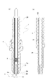
- the ignition plug which concerns on 1st Embodiment is shown, (a) is a partial cross section figure, (b) is the front view which assembled the center electrode, the terminal part, and the insulation cylinder.
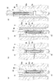
- the ignition plug which concerns on 2nd Embodiment is shown, (a) is partial sectional drawing, (b) is a partial expanded sectional view which shows the structure by which the electrically-conductive member and the terminal part are electrically connected, (c) is The partial expanded sectional view which shows the structure by which the electrically-conductive member and the terminal part are electrically insulated.
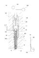
- the ignition plug which concerns on 3rd Embodiment is shown, (a) is a partial cross section figure, (b) is a partially expanded sectional view which shows the structure which baked the insulator, the insulation cylinder, and the electrically-conductive member integrally. It is the schematic which shows the process for shape
- the socket of 4th Embodiment is shown, (a) is front sectional drawing, (b) is the schematic which shows the connection of an antenna and a cable.
- -Spark plug- Embodiment 1 is a spark plug according to the present invention.
- FIG. 1 shows a spark plug according to the first embodiment.
- the spark plug 1 includes a terminal portion 20 that receives power from the outside, an electrode portion 2 that is electrically connected to the terminal portion 20, and a part of the electrode portion 2 and the terminal portion 20 that is connected to the electrode portion 2.
- this electrode part 2 is a cylindrical electrode that encloses a part of or all of the center electrode 2A, and a center electrode 2A having an electrode tip part for generating a spark discharge with the ground electrode 5 at the tip.
- the insulating cylinder 2B is configured, and a conductive member 21 is provided on the outer peripheral surface of the insulating cylinder 2B.
- one end of the terminal portion 20 is exposed to the outside and is electrically connected to the secondary electrode side of the ignition coil, and the other end shaft-shaped portion in contact with the center electrode 2A is the shaft of the insulator 3. The structure is inserted into the hole 30.
- the conductive member 21 provided on the outer peripheral surface of the insulating cylinder 2B is electrically connected to the terminal portion 20 that receives power from the outside.
- the high voltage for the spark discharge and the electromagnetic wave supplied as energy to the spark discharge prevent the mixer circuit (the high voltage (discharge current) for the spark discharge and the electromagnetic wave from flowing back to the respective supply sources.
- Power is supplied to the terminal unit 20 from a secondary electrode side of an ignition coil (not shown) and an electromagnetic wave oscillator (not shown) via a mixer device (not shown) provided with a circuit.
- a spark discharge due to a discharge direct current occurs between the ground electrode side end of the conductive member 21 and the ground electrode 5.
- the ground electrode side end of the conductive member 21 is annular and has a larger area than the pointed center electrode 2A, so the electric field strength is low. Further, since the tip portion of the center electrode 2A protrudes from the end portion on the ground electrode side of the conductive member 21, the distance from the ground electrode 5 is shorter from the tip portion of the center electrode 2A.
- the insulator 3 is formed by a known method, for example, an alumina powder is formed by a hydrostatic press with ceramics based on alumina (AL 2 O 3 ) having high insulation and heat and corrosion resistance, and a grinding device, a grindstone, etc. Then, the insulator 3 is manufactured by firing at around 1600 ° C.
- a high melting point and oxidation-resistant noble metal for example, platinum alloy or iridium
- a high melting point and oxidation-resistant noble metal for example, platinum alloy or iridium
- the conductive member 21 is not particularly limited as long as it is a metal conductor, but for example, stainless steel, silver, copper, gold, aluminum, tungsten, molybdenum, titanium, zirconium, niobium, tantalum, bismuth, lead, tin, or the main component thereof.
- An alloy for example, stainless steel
- a coating material eg, titanium coating
- the thickness is about 0.04 mm to 0.2 mm, preferably about 0.06 mm to 0.1 mm.
- the outer peripheral surface of the insulating cylinder 2B can be coated.
- the insulating cylinder 2B is preferably made of ceramics based on alumina (AL 2 O 3 ) or the like having high insulation properties and heat and corrosion resistance.
- the terminal portion 20 has one end exposed to the outside receiving power from the ignition coil, and the other end inserted into the shaft hole 30 and connected to the center electrode 2A.
- the metal shell 4 is a substantially cylindrical metal case.
- the metal shell 4 supports the outer periphery of the insulator 3 and accommodates the insulator 3.
- the inner peripheral surface of the front end portion of the metal shell 4 is separated from the outer peripheral surface of the front end portion of the insulator 3 with a gap.
- a male screw portion 41 is formed as an attachment structure for attachment to the internal combustion engine.
- the spark plug 1 is screwed and fixed to the cylinder head by screwing the male screw portion 41 of the metal shell 4 into the female screw portion (not shown) of the plug hole of the cylinder head.
- a wrench fitting portion 40 into which a plug wrench is fitted is formed on the upper part of the metal shell 4.
- powdery talc (talc) is filled as a sealing member, and the end part is crimped.
- the ground electrode 5 forms a discharge gap in which spark discharge occurs with the center electrode 2.
- the ground electrode 5 includes a ground electrode body 5b and a ground electrode tip 5a.
- the ground electrode body 5b is a curved plate-like conductor. One end side of the ground electrode main body 5 b is joined to the front end surface of the metal shell 4.
- the ground electrode body 5b extends from the front end surface of the metal shell 4 along the axis of the spark plug 1 and bends approximately 90 ° inward, and the front end side where the ground electrode tip 5a is provided is provided at the front end of the center electrode 2A. It faces the formed electrode tip part.
- the assembly of the center electrode 2A, the insulating cylinder 2B, the conductive member 21 and the terminal portion 20 is not particularly limited, but in the present embodiment, as shown in FIG.
- a locking member 23 formed with an outer peripheral stepped portion that locks the end of the conductive member 21 is joined by joining means such as brazing welding at the joint W1.
- the locking member 23 has an outer diameter other than the stepped portion that is substantially the same as the inner diameter of the conductive member 21, and is inserted from the ground electrode side end of the conductive member 21.
- the front end 2B1 of the insulating cylinder 2B divided into the front end 2B1 and the rear end 2B2 is brought into contact with the end of the locking member 23 on the side opposite to the ground electrode, and the other end of the front end 2B1 is centered on the other end.
- the large diameter portion of the electrode 2A is locked.
- the rear end 2B2 of the insulating cylinder 2B and the elastic member 24 are arranged coaxially with the center electrode 2A.
- the elastic member 24 uses, for example, a winding spring, and assists in joining the terminal portion 20 and the center electrode 2A. In this state, the terminal portion 20 is inserted into the conductive member 21, and the elastic member 24 is pushed down to be electrically connected to the center electrode 2A.
- a male screw is engraved on the outer peripheral portion of the shaft-like portion inserted into the shaft hole 30, and a female screw is engraved on a corresponding portion of the inner surface of the shaft hole 30 of the insulator 3.
- the male screw of the terminal portion 20 is screwed and fixed to the female screw of the shaft hole 30.
- the center electrode 2A, the insulating cylinder 2B, and the terminal portion 20 may be joined to the insulator 3 by appropriately joining means such as a ceramic adhesive without engraving screws in the shaft hole 30 and the terminal portion 20. it can. Thereafter, the insulator 3 including the center electrode 2A, the insulating cylinder 2B, and the terminal portion 20 is attached to the metal shell 4, and the spark plug 1 is completed.
- spark discharge is generated between the electrode tip portions 5a of the five, that is, in the discharge gap.
- the electromagnetic wave (microwave) supplied as energy to the spark discharge has a characteristic of flowing on the surfaces of the conductor and the dielectric, and therefore flows on the surfaces of the terminal portion 20 and the conductive member 21 and is joined to the conductive member 21.
- Irradiation supply is performed in an annular shape from the end surface on the ground electrode side of the locking member 23 toward the ground electrode 5 side (combustion chamber side).
- the irradiated electromagnetic wave is supplied as energy to the discharge plasma generated in the discharge gap formed between the center electrode 2A and the ground electrode 5, and the plasma is maintained and expanded.
- the peak portion of the electric field intensity of the irradiated electromagnetic wave is deviated from the axis of the center electrode 2A and deviates from the peak portion of the electric field intensity due to the discharge current.
- Electrodes flow on the surface of the conductive member 21 that is a cylindrical conductor, and electromagnetic waves (microwaves) are used as energy for spark discharge (spark discharge) generated between the center electrode 2A and the ground electrode 5. Is supplied and the discharge plasma expands. Thereby, ignition stability can be improved. As a result, the internal combustion engine using the spark plug can perform ultra lean combustion, and can reduce fuel consumption and CO2 emission. Further, since the discharge current for the spark discharge is emitted in an annular shape surrounding the center electrode 2A and the electromagnetic wave supplied as energy to the spark discharge is emitted in an annular shape surrounding the center electrode 2A, the tip of the center electrode 2A and the ground electrode 5 are discharged.
- the electric field strength generated by the discharge current and the electromagnetic wave between the two and the electric field strength due to the discharge current is highest at the axis of the center electrode 2A, but the electric field strength due to the electromagnetic wave is outside the axis of the center electrode 2A (The portion having the highest temperature at the center of the shaft center and the high temperature portion does not concentrate on the shaft core portion of the center electrode 2A. As a result, it is possible to effectively prevent melting of the tip of the electrode tip, which is the tip of the center electrode 2.
- the conductive member 21 can be electrically insulated from the terminal portion 20 that receives power from the outside. By electrically insulating, when a socket described later is used, the electromagnetic wave flows on the surface of the conductive member 21 by capacitive coupling, but can reliably prevent the discharge high voltage from flowing to the conductive member 21. .
- a resistance pattern is applied to one surface of a thin plate-shaped body mainly composed of an insulator such as alumina, a metal coating serving as a conductor is applied to the other surface, and the surface subjected to the metal coating is an outer peripheral surface.
- the tube is wound into a tube shape, and the center electrode 2 is joined to one end of the open end, and the terminal portion 20 or a joining member to the terminal portion 20 is joined to multiple ends by brazing or welding or the like.
- the tubular insulator constitutes the insulating cylinder 2 ⁇ / b> B
- the metal coating on the outer peripheral surface thereof constitutes the conductive member 21.
- a plate-shaped body to be wound is formed by cutting a large-sized plate-shaped body having a metal coating on one surface and a plurality of resistance patterns on the other surface, as shown in FIG. Compared with the case where it does, it can aim at a significant cost reduction.
- the second embodiment is a spark plug according to the present invention.
- This spark plug differs from the spark plug of the first embodiment in the attachment structure of the center electrode 2A, the insulating cylinder 2B, the conductive member 21 and the insulator 3, and the attachment structure of the terminal portion 20 and the insulator 3.
- FIG. 2 shows a spark plug according to the second embodiment.
- the spark plug 1 includes a terminal portion 20 that receives power from the outside, an electrode portion 2 that is electrically connected to the terminal portion 20, and a shaft hole 30 into which the electrode portion 2 is fitted.
- the electrode portion 2 is composed of an electrode tip portion 2A and an insulating cylinder 2B.
- a large-diameter portion of the center electrode 2A1 (tip center electrode) having an electrode tip portion having a large diameter on the counter electrode tip portion is locked to an inner peripheral portion of one end (ground electrode side) of the insulating cylinder 2B.
- a stepped portion is provided, and a thin cylindrical conductor having a thickness of about 0.04 mm to 0.2 mm, preferably about 0.06 mm to 0.1 mm, for example, stainless steel, is inserted into the outer peripheral surface.
- the outer periphery is large at the end of the center electrode 2A2 (rear end center electrode) connected to the center electrode 2A1 in the insulating cylinder 2B through the powdered resistor R without providing the electrode tip portion of the center electrode 2A.
- a step having a diameter is provided, and the end of the conductive member 21 is joined to the step.
- the resistor R is composed of a composite powder material (resistor composition powder) in which glass powder, metal powder, and carbon powder are mixed, and is sealed at a temperature higher than the glass softening temperature (900 ° C to 1000 ° C) for insulation.
- the cylinder 2B, the center electrode 2A (the center electrode 2A1 and the center electrode 2A2), and the conductive member 21 are integrally formed.
- the integrally formed insulating cylinder 2B, the center electrode 2A, and the conductive member 21 lock the step formed at the end of the center electrode 2A2 to the step formed in the shaft hole 30 of the insulator 3.
- the terminal portion 20 is inserted from the side of the insulator 3 opposite to the ground electrode.
- a powder P conductive mixed powder obtained by adding a conductive glass powder to a copper / tungsten mixed powder, a chromium / nickel mixed powder or a titanium / nickel mixed powder between the opposing end surfaces of the center electrode 2A and the terminal portion 20 is used. It is interposed and sealed at a temperature higher than the glass softening temperature (900 ° C. to 1000 ° C.).
- the inside of the insulator 3 incorporating the insulating cylinder 2B, the center electrode 2A, the conductive member 21 and the terminal portion 20 is configured, and then the insulator 3 is attached to the metal shell 4 to complete the spark plug 1. To do.
- the conductive member 21 and the center electrode 2A2 can be electrically insulated.
- electrically insulating when a socket described later is used, the electromagnetic wave flows on the surface of the conductive member 21 by capacitive coupling, but can reliably prevent the discharge high voltage from flowing to the conductive member 21. .
- a high voltage for spark discharge fed from the terminal portion 20 flows through the axial center of the terminal portion 20 and the center electrode 2 ⁇ / b> A, and the tip of the center electrode 2 ⁇ / b> A.
- a spark discharge (spark discharge) is generated between the electrode tip portion of the electrode and the electrode tip portion 5a of the ground electrode 5, that is, in the discharge gap. Since the electromagnetic wave (microwave) supplied as energy to the spark discharge has a characteristic of flowing on the surfaces of the conductor and the dielectric, it flows on the surfaces of the terminal portion 20 and the conductive member 21, and the end surface on the ground electrode side of the conductive member 21. To the ground electrode 5 side (combustion chamber side).
- the irradiated electromagnetic wave is supplied as energy to the discharge plasma generated in the discharge gap formed between the center electrode 2A and the ground electrode 5, and the plasma is maintained and expanded.
- the peak portion of the electric field intensity of the irradiated electromagnetic wave is deviated from the axis of the center electrode 2A and deviates from the peak portion of the electric field intensity due to the discharge current.
- the electric field strength generated by the discharge current and the electromagnetic wave is the same as that of the first embodiment.
- the electrode which is the highest on the outer side (annular centered on the shaft core) of the electrode 2 and which is at a high temperature does not concentrate on the shaft core portion of the center electrode 2 and is the tip portion of the center electrode 2 It is possible to effectively prevent melting at the tip of the tip portion 25a.
- each member is manufactured by sealing with a composite powder material or resistor composition powder, when it is attached to an internal combustion engine, the gas generated in the combustion chamber is stable without leaking from the plug to the outside. Can be used.
- the resistor can be easily configured in the plug, it is possible to effectively prevent (electricity prevention) noise generated during spark discharge that affects the electronic equipment of the automobile.
- the third embodiment is a spark plug according to the present invention.
- the spark plug 1 has a mounting structure for the center electrode 2A, the insulating cylinder 2B, the conductive member 21 and the insulator 3 relative to the spark plug of the first embodiment (this embodiment).
- the mounting method (molding method) between the terminal portion 20 and the insulator 3 is different.
- the description of the same configuration as that of the first embodiment, such as the metal shell 4 and the ground electrode 5, is omitted.
- the insulator 3 is constructed by firing integrally with the insulating cylinder 2B and the conductive member 21. Specifically, as shown in FIG. 4, the insulator 3 is formed by using, for example, a cold isostatic pressing method called a rubber press method.
- a raw material powder 3A mainly composed of alumina (AL 2 O 3 ) or the like is filled in a cavity 80a formed of a rubber mold 80, and a press pin 81 attached to an upper lid 81 from an open end is disposed (FIG. 4 ( a)), and a pressure of 30 to 100 MPa is applied to the rubber die 80 from the pressurizing fluid passage 8a of the molding apparatus body 8 to compress the raw material powder 3A, thereby molding the molded body 3B (see FIG. 4 (b)).
- the cylindrical conductor tube 21A (conductive member 21) is disposed on the upper lid 81 so as to be coaxial with the press pin 81, whereby the insulator 3, the insulating tube 2B and the conductive member 21 can be integrally formed.
- the conductor cylinder 21A is fitted into the groove formed in the flange portion of the press pin 81 to such an extent that it can be easily attached and detached to maintain the coaxial state. Also, the conductor cylinder 21A is applied with pressure evenly on the surface of the conductor cylinder 21A so that it becomes cylindrical when deformed by applying pressure, and becomes a right cylinder after pressing, for example, before pressing It is preferable to use a drum shape with a bulging center. Thereafter, only the press pin 81 is removed while leaving the conductor cylinder 21A, and a grinding process is performed to insert a support pin to form an outer shape portion into a desired shape, and firing is performed after the grinding process. Thereby, the insulator 3, the insulating cylinder 2B (the insulating cylinder 2B is a part of the insulator 3), and the conductive member 21 shown in FIG. 3B can be integrally fired.
- the press pin 81 has a tip portion with a small diameter so that a stepped portion for locking a large diameter portion of a center electrode (tip center electrode) having an electrode tip portion with a large diameter at the counter electrode tip portion is formed.
- a stepped structure is used.
- an insulating washer is interposed between the flange portion 20a of the terminal portion 20 and the end surface of the conductive member 21 shown in FIG.
- a high voltage for spark discharge fed from the terminal portion 20 flows through the axial centers of the terminal portion 20 and the center electrode 2A, and the center Spark discharge (spark discharge) is generated between the electrode tip portion at the tip of the electrode 2A and the electrode tip portion 5a of the ground electrode 5, that is, in the discharge gap.
- the electromagnetic wave (microwave) supplied as energy to the spark discharge has a characteristic of flowing on the surfaces of the conductor and the dielectric, it flows on the surfaces of the terminal portion 20 and the conductive member 21, and the end surface on the ground electrode side of the conductive member 21.
- the irradiated electromagnetic wave is supplied as energy to the discharge plasma generated in the discharge gap formed between the center electrode 2A and the ground electrode 5, and the plasma is maintained and expanded.
- the peak portion of the electric field intensity of the irradiated electromagnetic wave is deviated from the axis of the center electrode 2A and deviates from the peak portion of the electric field intensity due to the discharge current.
- the spark plug according to the present embodiment can be manufactured in the same process as that of a normally used method for manufacturing an insulator for a spark plug, and the initial cost for new equipment investment can be reduced. Further, as in the second embodiment, since each member is sealed and manufactured using a composite powder material or a resistor composition powder, the gas generated in the combustion chamber when it is attached to the internal combustion engine from the plug. It can be used stably without leaking outside. In addition, since the resistor can be easily configured in the plug, it is possible to effectively prevent (electricity prevention) noise generated during spark discharge that affects the electronic equipment of the automobile.
- the press pin 81 used in the molding by the rubber press method can be used as it is as the connection portion and the center electrode.
- the tip of the press pin 81 has a length that reaches the lower lid 83.
- the axial portion of the press pin 81 is formed such that a resistance pattern is formed on the surface of a cube whose main surface is an insulator such as alumina and whose bottom surface is a regular polygon (preferably a regular square), and the center electrode 2 is formed at one end of the resistance pattern. It can also be set as the center electrode with a resistance comprised by joining the junction part with the terminal part 20 or the terminal part 20 to multiple ends by brazing, welding, etc. Thereby, a center electrode and a resistor can be comprised easily. Further, by cutting from a large plate-like body having a plurality of resistance patterns on the surface in advance to form the shaft portion of the press pin 81, the manufacturing cost can be greatly reduced.
- a spark plug socket 100 is a spark plug socket device or an ignition coil (ignition coil) that is detachably attached to the spark plug 1 according to the first to third embodiments attached to a cylinder head of an internal combustion engine.
- Coil A joint part of an integrated socket device with an ignition plug, which is connected to the ignition plug 1 from the ignition coil via a distributor, and is an integrated type with the ignition coil and connected to the ignition plug 1 Including.
- the socket 100 is oscillated from an electromagnetic wave oscillator 103 to a socket body 110, a power feeding unit 120 disposed in the socket body 110, an annular antenna 101 that radiates electromagnetic waves, and the antenna 101. And a cable 102 (for example, a coaxial cable) for supplying electromagnetic waves.
- a cable 102 for example, a coaxial cable
- the socket body 110 is formed in a cylindrical shape and has an insertion hole 110a therein.
- the joint portion of the socket body 110, particularly the spark plug 1, is made of an elastic member that can be elastically deformed, such as elastically deformable rubber.
- the power feeding unit 120 is not particularly limited as long as it is a structure that electrically connects the terminal unit 20 protruding from the spark plug 1 and the secondary coil side of the ignition coil.
- a spring is used so as not to be cut by a slight deviation.
- the power feeding unit 20 may be referred to as a conductive spring 120.
- the power feeding unit 120 constitutes a low-pass filter, and it is possible to prevent electromagnetic waves emitted from the antenna 101 from leaking to the ignition coil 104 connected to the discharge power source. it can.
- the location of the antenna 101 is not particularly limited, but when the socket 100 is attached to the spark plug 1, the position of the conductive member 21 in the spark plug 1 and the position in the axial direction correspond to each other.
- the socket body 110 is disposed on the inner peripheral surface of the insertion hole 110a.
- a ground 102 a that is joined to the metal shell 4 of the spark plug is provided. It is preferable that the contact portion of the earth 102a with the metal shell 4 is made of an elastic member such as a spring and is not cut by a slight shift of the socket 100.
- the ground 102a may be connected to the cylinder head of the internal combustion engine, for example, instead of the metal shell 4 as long as it is connected to the reference potential point.
- the cable 102 may be wired from the outer peripheral surface of the socket main body 110 corresponding to the position of the antenna 101 to the outside of the socket main body 110. However, as shown in FIG. By being configured to be embedded in the cylinder head, wear and breakage can be suppressed without rubbing against the peripheral surface of the plug mounting hole of the cylinder head.
- the antenna 101 can be connected to the cable 102 by forming the antenna 101 into a cylindrical shape and connecting the arbitrary peripheral surface of the antenna 101 to the cable 102. As shown in b), it is preferable that a part of the peripheral surface of the antenna 101 is extended in the axial direction so that the arc length gradually decreases and connected to the apex portion. By connecting in this way, reflection of electromagnetic waves at the junction between the cable 102 and the antenna 101 can be suppressed.
- the antenna 101 can be configured by winding a number of cables 102 around the outer peripheral surface near the opening end of the socket body 110.
- the cable 102 is a coaxial cable
- a central inner conductor (copper wire) is wound.
- the socket body 110 may be formed by configuring the antenna 101 by previously weaving a copper wire on the outer peripheral surface or the inner peripheral surface of the socket main body 110.
- a coaxial resonator 111 constituting a choke is disposed on the ignition coil side of the antenna 101 on the inner peripheral surface of the insertion hole 110a of the socket body 110.
- the coaxial resonator 111 is a conductor having a cylindrical body having an inner diameter substantially the same as the insertion hole 110a and having a cavity with an L-shaped cross section inside, and has an axial cavity length. Is configured to be ⁇ / 4 with respect to the frequency ⁇ of the electromagnetic wave that supplies.
- the electromagnetic wave is allowed to enter from the opening. As a result, it is possible to reliably prevent the electromagnetic wave irradiated from the antenna 101 from leaking to the ignition coil 104 connected to the discharge power source.
- the cylindrical conductive member 21 and the terminal portion 20 are insulated. As described above, even if the conductive member 21 and the terminal portion 20 are electrically connected, the ground electrode side end portion of the conductive member 21 is more grounded than the ground electrode side end portion (electrode tip portion) of the center electrode 2A. Since the center electrode 2A is smaller than the conductive member 21 and the end area is smaller than that of the conductive member 21, the high voltage for discharge causes dielectric breakdown between the conductive member 21 and the ground electrode 5. However, by insulating between the conductive member 21 and the terminal portion 20, it is possible to reliably prevent a high voltage from flowing through the conductive member 21.
- the high voltage for discharge receives an ignition signal from a control device (for example, an ECU in the case of an internal combustion engine), and from the secondary electrode side of the ignition coil 104 via the spring-shaped power feeding unit 120, the spark plug 1 terminal portion 20 flows. Then, a spark discharge is generated in a discharge gap formed between the electrode tip portion of the center electrode 2A and the electrode tip portion 5a of the ground electrode 5.
- a control device for example, an ECU in the case of an internal combustion engine
- the electromagnetic wave (microwave) supplied as energy to the spark discharge is irradiated from the antenna 101 through the cable 102 from the electromagnetic wave oscillator 103. Since the annular antenna 101 and the cylindrical conductive member 21 are capacitively coupled, the supplied electromagnetic wave flows on the surface of the conductive member 21 and passes through the ground electrode side end surface of the conductive member 21 to the axis of the center electrode 2A. It is discharged in an annular shape so as to surround, and the high temperature at the axial core portion of the center electrode 2 is prevented.
- the socket according to the present embodiment has a structure in which a joint portion with a spark plug of a normally used socket device for an ignition plug or an ignition coil (ignition coil) integrated type is improved, so that the manufacturing cost is suppressed. can do.
- a mixer circuit is provided. Does not require a mixer device.
- a cylindrical conductor serving as an antenna is formed on the surface of the insulator 3 of the spark plug of the first to third embodiments. And the front-end
- the end of the cable 102 is connected to a substantially ring-shaped member having a diameter slightly smaller than the outer diameter of the insulator 3 in order to ensure an electrical connection with the antenna, and the socket 100 is connected to the spark plug 1. It is preferable that the ring-shaped member is configured to be elastically deformed (reduced in diameter) when mounted on the.
- the high voltage for the spark discharge passes through the center of the center electrode, and the electromagnetic wave (microwave) supplied as energy to the spark discharge is generated from the end surface on the ground electrode side of the conductive member.
- Discharged for spark discharge because it is discharged in an annular shape so as to surround the axis of the center electrode, and it is possible to prevent high temperature at the axis of the center electrode and to greatly reduce the electric loss.
- It can be suitably used for a plasma generator that supplies microwaves as energy for voltage and spark discharge.
- it can be widely used in automobiles, airplanes, ships and the like as an internal combustion engine such as an automobile engine using the spark plug and socket of the present invention.
- it can use for various internal combustion engines, such as a gasoline engine, a diesel engine, and a natural gas engine, as an internal combustion engine.
- the socket of the fourth embodiment can use a normal spark plug other than the spark plugs shown in the first to third embodiments.
- capacitive coupling is performed via the insulator 3 with the shaft-shaped portion inside the insulator 3 of the terminal portion that receives power from the outside.
- the electromagnetic wave supplied by capacitively coupling the annular antenna 101 and the conductor (inner conductor) disposed inside the ignition plug is supplied from the tip of the ignition plug into the combustion chamber.
- an inexpensive ordinary spark plug can be used although the flow of supplied electromagnetic waves is inferior to that in the case of capacitive coupling with the cylindrical conductive member 21.
- electromagnetic waves are concentrated in the center as compared with the spark plugs shown in the first to third embodiments, but sufficient microwaves are supplied into the combustion chamber. be able to.
Landscapes
- Engineering & Computer Science (AREA)
- Chemical & Material Sciences (AREA)
- Combustion & Propulsion (AREA)
- Mechanical Engineering (AREA)
- General Engineering & Computer Science (AREA)
- Physics & Mathematics (AREA)
- Optics & Photonics (AREA)
- Power Engineering (AREA)
- Electromagnetism (AREA)
- Spark Plugs (AREA)
- Ignition Installations For Internal Combustion Engines (AREA)
- Plasma Technology (AREA)
Abstract
Description
該電極部が嵌め込まれる軸孔が形成された絶縁碍子と、
該絶縁碍子の周囲を囲むように配置された主体金具と、
該主体金具の端面から延設され、前記電極部との間に火花放電が生じる放電ギャップを形成する接地電極とを備えた点火プラグであって、
前記電極部が、
接地電極との間で火花放電を生じさせるための電極チップ部を備えた中心電極と、
該中心電極を覆う筒状の絶縁筒とから構成され、
前記絶縁筒の外周面に、導電部材を設けた点火プラグである。
外部から供給される電磁波を照射する環状アンテナとを備え、
該環状アンテナと前記導電部材とを前記絶縁碍子を介して容量結合するようにしたソケットである。
-点火プラグ-
本実施形態1は、本発明に係る点火プラグである。
本実施形態の点火プラグは、筒状の導体である導電部材21の表面を電磁波が流れ、中心電極2Aと接地電極5との間で生じる火花放電(スパーク放電)にエネルギとして電磁波(マイクロ波)が供給され、放電プラズマが拡大する。これにより着火安定性を向上することができる。その結果、当該点火プラグを用いた内燃機関は、超希薄燃焼を可能とし、燃費及びCO2の排出量を低減することができる。また、火花放電のための放電電流は中心電極2Aの軸芯を、火花放電にエネルギとして供給される電磁波は、中心電極2Aを囲う環状に放出されるから、中心電極2Aの先端と接地電極5との間における、放電電流及び電磁波によって生じるそれぞれの電界強度は、放電電流による電界強度が中心電極2Aの軸芯が最も高くなるものの、電磁波による電界強度が中心電極2Aの軸芯よりも外側(軸芯を中心とした環状)で最も高くなり、高温となる部分が中心電極2Aの軸芯部分に集中することがない。これによって、中心電極2の先端部分である電極チップ部先端の溶損を有効に防止することができる。
実施形態1の変形例では、アルミナ等の絶縁体を主成分とする薄い板状体の一面に抵抗パターンを、他面に導体となる金属コーティングを施し、金属コーティングを施した面が外周面となるようにチューブ状に巻回し、開放端の一端に中心電極2、多端に端子部20又は端子部20との接合部材を内周面の抵抗パターンと蝋付けや溶接等によって接合する。これにより、チューブ状の絶縁体が絶縁筒2Bを、その外周面の金属コーティングが導電部材21を構成する。この際、巻回する大きさの板状体を、予め一面に金属コーティング、他面に複数の抵抗パターン施した大判の板状体から切断して形成することで、図1に示すように構成する場合と比べて大幅なコストダウンを図ることができる。
-点火プラグ-
本実施形態2は、本発明に係る点火プラグである。この点火プラグは、実施形態1の点火プラグと比べて、中心電極2A、絶縁筒2B、導電部材21及び絶縁碍子3の取付構造並びに端子部20と絶縁碍子3との取付構造が異なる。主体金具4、接地電極5等、実施形態1と同様の構成については説明を省略する。
本実施形態の点火プラグは、実施形態1と同様に、放電電流及び電磁波によって生じる電界強度は、放電電流による電界強度は中心電極2の軸芯が最も高くなるものの、電磁波による電界強度は、中心電極2の軸芯よりも外側(軸芯を中心とした環状)で最も高くなり、高温となる部分が中心電極2の軸芯部分に集中することがなく、中心電極2の先端部分である電極チップ部25a先端の溶損を有効に防止することができる。また、各部材を複合粉末材料又は抵抗体組成用粉末を使って封着して製造するから、内燃機関に取り付けたときに、燃焼室で発生するガスがプラグ内から外部に漏れることなく安定して使用することができる。また、プラグ内に抵抗体を容易に構成することができるから、自動車の電子機器に影響を与える、火花放電の際に生じるノイズを有効に防止(電雑防止)することができる。
-点火プラグ-
本実施形態3は、本発明に係る点火プラグである。この点火プラグ1は、実施形態2の点火プラグと同様に、実施形態1の点火プラグと比べて、中心電極2A、絶縁筒2B、導電部材21及び絶縁碍子3の相互の取付構造(本実施形態においては成形方法)並びに端子部20と絶縁碍子3との取付構造(成形方法)が異なる。主体金具4、接地電極5等、実施形態1と同様の構成については説明を省略する。
本実施形態の点火プラグは、通常用いられる点火プラグ用絶縁碍子の製造方法と同様の工程で製造することができ、新たな設備投資などにかかる初期費用を低減することができる。また、実施形態2と同様に、各部材を複合粉末材料又は抵抗体組成用粉末を使って封着して製造するから、内燃機関に取り付けたときに、燃焼室で発生するガスがプラグ内から外部に漏れることなく安定して使用することができる。また、プラグ内に抵抗体を容易に構成することができるから、自動車の電子機器に影響を与える、火花放電の際に生じるノイズを有効に防止(電雑防止)することができる。
実施形態3の変形例では、ラバープレス法での成形の際に使用するプレスピン81を接続部及び中心電極としてそのまま使用することができる。この場合、プレスピン81の先端は、下蓋83に達する長さとすることが好ましい。
-点火プラグ用のソケット-
本実施形態における点火プラグ用のソケット100は、内燃機関のシリンダヘッドに取り付けられる実施形態1~実施形態3に係る点火プラグ1に、着脱自在に取り付けられる点火プラグ用のソケット装置又はイグニッションコイル(点火コイル)一体型のソケット装置の点火プラグとの接合部分であって、点火コイルからディストリビュータを介して点火プラグ1に接続するもの、点火コイルと一体型であって、点火プラグ1と接続するものを含む。
本実施形態のソケットは、通常使用される点火プラグ用のソケット装置又はイグニッションコイル(点火コイル)一体型のソケット装置の点火プラグとの接合部分に改良を加えた構造であるため、製造コストを抑制することができる。また、点火プラグの筒状の導電部材と筒状のアンテナとが、容量結合されソケット内にローパスフィルタを構成するコイルスプリングやチョークを構成する同軸共振器を配設しているからミキサー回路を備えたミキサー装置を必要としない。
実施形態4の変形例1では、実施形態1~実施形態3の点火プラグの絶縁碍子3の表面にアンテナとなる筒状の導体を形成する。そして、ケーブル102の先端と絶縁碍子3表面のアンテナとを電気的に接合するように構成する。この際、アンテナと電気的に確実に接合するようにするため、ケーブル102の先端を、絶縁碍子3の外径よりも僅かに小径となる略リング状部材に接続し、ソケット100を点火プラグ1に装着したとき、このリング状部材が弾性変形するように(縮径するように)構成することが好ましい。
2 電極部
2A 中心電極
2B 絶縁筒
20 端子部
21 導電部材
3 絶縁碍子
30 軸孔
4 主体金具
5 接地電極
5a 接地電極チップ部
5b 接地電極本体部
100 ソケット
101 アンテナ
102 ケーブル
110 ソケット本体
120 給電部(給電スプリング)
Claims (6)
- 外部からの給電を受ける端子部及び該端子部と電気的に接続される電極部と、
該電極部が嵌め込まれる軸孔が形成された絶縁碍子と、
該絶縁碍子の周囲を囲むように配置された主体金具と、
該主体金具の端面から延設され、前記電極部との間に火花放電が生じる放電ギャップを形成する接地電極とを備えた点火プラグであって、
前記電極部が、
接地電極との間で火花放電を生じさせるための電極チップ部を備えた中心電極と、
該中心電極を覆う筒状の絶縁筒とから構成され、
前記絶縁筒の外周面に、導電部材を設けた点火プラグ。 - 前記導電部材が、端子部と電気的に絶縁されている請求項1に記載の点火プラグ。
- 前記絶縁碍子、絶縁筒及び導電部材を一体的に焼成して構成した請求項1に記載の点火プラグ。
- 請求項1から請求項3に記載の点火プラグに装着するソケットであって、
前記点火プラグの端子部と電気的に接続される給電部と、
外部から供給される電磁波を照射する円環状のアンテナとを備え、
該環状アンテナと前記導電部材とを前記絶縁碍子を介して容量結合するようにしたソケット。 - 前記給電部が、ローパスフィルタを構成するコイルスプリングである請求項4に記載のソケット。
- 前記環状アンテナより点火コイル側にチョークを構成する同軸共振器を配設した請求項4又は請求項5に記載のソケット。
Priority Applications (3)
| Application Number | Priority Date | Filing Date | Title |
|---|---|---|---|
| US15/305,974 US20170152829A1 (en) | 2014-04-22 | 2014-04-22 | Spark plug and socket |
| JP2016515182A JPWO2015163366A1 (ja) | 2014-04-22 | 2015-04-22 | 点火プラグ及びソケット |
| EP15783637.0A EP3136522A4 (en) | 2014-04-22 | 2015-04-22 | Spark plug and socket |
Applications Claiming Priority (2)
| Application Number | Priority Date | Filing Date | Title |
|---|---|---|---|
| JP2014088631 | 2014-04-22 | ||
| JP2014-088631 | 2014-04-22 |
Publications (1)
| Publication Number | Publication Date |
|---|---|
| WO2015163366A1 true WO2015163366A1 (ja) | 2015-10-29 |
Family
ID=54332529
Family Applications (1)
| Application Number | Title | Priority Date | Filing Date |
|---|---|---|---|
| PCT/JP2015/062234 WO2015163366A1 (ja) | 2014-04-22 | 2015-04-22 | 点火プラグ及びソケット |
Country Status (4)
| Country | Link |
|---|---|
| US (1) | US20170152829A1 (ja) |
| EP (1) | EP3136522A4 (ja) |
| JP (1) | JPWO2015163366A1 (ja) |
| WO (1) | WO2015163366A1 (ja) |
Cited By (2)
| Publication number | Priority date | Publication date | Assignee | Title |
|---|---|---|---|---|
| WO2017073760A1 (ja) * | 2015-10-30 | 2017-05-04 | イマジニアリング株式会社 | 点火プラグ、及び点火装置 |
| CN109083797A (zh) * | 2018-10-26 | 2018-12-25 | 大连民族大学 | 一种具有出气斜孔及多阳极结构的等离子体点火器 |
Families Citing this family (4)
| Publication number | Priority date | Publication date | Assignee | Title |
|---|---|---|---|---|
| US10036361B2 (en) * | 2014-08-12 | 2018-07-31 | Imagineering, Inc. | Ignition device |
| US10340664B2 (en) * | 2015-01-30 | 2019-07-02 | Borgwarner Ludwigsburg Gmbh | Corona ignition device |
| JP6528573B2 (ja) * | 2015-07-13 | 2019-06-12 | 株式会社デンソー | 点火装置 |
| WO2023009623A1 (en) * | 2021-07-28 | 2023-02-02 | Milwaukee Electric Tool Corporation | Spark plug socket |
Citations (2)
| Publication number | Priority date | Publication date | Assignee | Title |
|---|---|---|---|---|
| JP2009516342A (ja) * | 2005-11-14 | 2009-04-16 | ルノー・エス・アー・エス | 内燃エンジン用スパークプラグ |
| WO2011016569A1 (ja) * | 2009-08-06 | 2011-02-10 | イマジニアリング株式会社 | 混合器、整合器、点火ユニット、及びプラズマ生成器 |
Family Cites Families (5)
| Publication number | Priority date | Publication date | Assignee | Title |
|---|---|---|---|---|
| JPH0917550A (ja) * | 1995-06-30 | 1997-01-17 | Yazaki Corp | 高圧ケーブル装置 |
| JP4905371B2 (ja) * | 2008-01-18 | 2012-03-28 | 株式会社デンソー | プラズマ式点火装置 |
| JP6387490B2 (ja) * | 2013-06-18 | 2018-09-12 | イマジニアリング株式会社 | 点火プラグ及びプラズマ発生装置 |
| JP6347053B2 (ja) * | 2013-08-01 | 2018-06-27 | イマジニアリング株式会社 | 点火プラグ及びプラズマ発生装置 |
| US9903337B2 (en) * | 2013-09-02 | 2018-02-27 | Imagineering, Inc. | Plasma generator and internal combustion engine |
-
2014
- 2014-04-22 US US15/305,974 patent/US20170152829A1/en not_active Abandoned
-
2015
- 2015-04-22 JP JP2016515182A patent/JPWO2015163366A1/ja not_active Ceased
- 2015-04-22 WO PCT/JP2015/062234 patent/WO2015163366A1/ja active Application Filing
- 2015-04-22 EP EP15783637.0A patent/EP3136522A4/en not_active Withdrawn
Patent Citations (2)
| Publication number | Priority date | Publication date | Assignee | Title |
|---|---|---|---|---|
| JP2009516342A (ja) * | 2005-11-14 | 2009-04-16 | ルノー・エス・アー・エス | 内燃エンジン用スパークプラグ |
| WO2011016569A1 (ja) * | 2009-08-06 | 2011-02-10 | イマジニアリング株式会社 | 混合器、整合器、点火ユニット、及びプラズマ生成器 |
Non-Patent Citations (1)
| Title |
|---|
| See also references of EP3136522A4 * |
Cited By (2)
| Publication number | Priority date | Publication date | Assignee | Title |
|---|---|---|---|---|
| WO2017073760A1 (ja) * | 2015-10-30 | 2017-05-04 | イマジニアリング株式会社 | 点火プラグ、及び点火装置 |
| CN109083797A (zh) * | 2018-10-26 | 2018-12-25 | 大连民族大学 | 一种具有出气斜孔及多阳极结构的等离子体点火器 |
Also Published As
| Publication number | Publication date |
|---|---|
| EP3136522A4 (en) | 2017-05-10 |
| JPWO2015163366A1 (ja) | 2017-05-25 |
| US20170152829A1 (en) | 2017-06-01 |
| EP3136522A1 (en) | 2017-03-01 |
Similar Documents
| Publication | Publication Date | Title |
|---|---|---|
| WO2015163366A1 (ja) | 点火プラグ及びソケット | |
| JP6387490B2 (ja) | 点火プラグ及びプラズマ発生装置 | |
| JP6347053B2 (ja) | 点火プラグ及びプラズマ発生装置 | |
| JP5632993B2 (ja) | 混合器、整合器、点火ユニット、及びプラズマ生成器 | |
| JP5385427B2 (ja) | 点火プラグ、及び、点火装置 | |
| US9644598B2 (en) | Corona ignition device | |
| EP3172430B1 (en) | Ignition unit and system | |
| US8742652B2 (en) | HF ignition device | |
| WO2016013615A1 (ja) | 点火プラグ | |
| JP5859909B2 (ja) | ケーブル一体型プラグおよびその製造方法 | |
| JP6044399B2 (ja) | 内燃機関用スパークプラグ | |
| JP2019525430A (ja) | コロナ点火装置および組立方法 | |
| JP5411822B2 (ja) | 点火システム及び点火プラグ | |
| JP6677867B2 (ja) | ソケット及び点火プラグ | |
| US20220082074A1 (en) | Ignition unit and motorized product | |
| JP2005180446A (ja) | 内燃機関内の空気・燃料混合気に点火するための装置 | |
| JP5829573B2 (ja) | 点火装置 | |
| WO2016088899A2 (ja) | 点火装置、点火システム、及びコネクタ |
Legal Events
| Date | Code | Title | Description |
|---|---|---|---|
| 121 | Ep: the epo has been informed by wipo that ep was designated in this application |
Ref document number: 15783637 Country of ref document: EP Kind code of ref document: A1 |
|
| ENP | Entry into the national phase |
Ref document number: 2016515182 Country of ref document: JP Kind code of ref document: A |
|
| NENP | Non-entry into the national phase |
Ref country code: DE |
|
| REEP | Request for entry into the european phase |
Ref document number: 2015783637 Country of ref document: EP |
|
| WWE | Wipo information: entry into national phase |
Ref document number: 2015783637 Country of ref document: EP |
|
| WWE | Wipo information: entry into national phase |
Ref document number: 15305974 Country of ref document: US |