WO2017073760A1 - 点火プラグ、及び点火装置 - Google Patents
点火プラグ、及び点火装置 Download PDFInfo
- Publication number
- WO2017073760A1 WO2017073760A1 PCT/JP2016/082148 JP2016082148W WO2017073760A1 WO 2017073760 A1 WO2017073760 A1 WO 2017073760A1 JP 2016082148 W JP2016082148 W JP 2016082148W WO 2017073760 A1 WO2017073760 A1 WO 2017073760A1
- Authority
- WO
- WIPO (PCT)
- Prior art keywords
- space
- plasma
- center electrode
- cylindrical conductor
- insulator
- Prior art date
Links
Images
Classifications
-
- F—MECHANICAL ENGINEERING; LIGHTING; HEATING; WEAPONS; BLASTING
- F02—COMBUSTION ENGINES; HOT-GAS OR COMBUSTION-PRODUCT ENGINE PLANTS
- F02P—IGNITION, OTHER THAN COMPRESSION IGNITION, FOR INTERNAL-COMBUSTION ENGINES; TESTING OF IGNITION TIMING IN COMPRESSION-IGNITION ENGINES
- F02P3/00—Other installations
- F02P3/01—Electric spark ignition installations without subsequent energy storage, i.e. energy supplied by an electrical oscillator
-
- F—MECHANICAL ENGINEERING; LIGHTING; HEATING; WEAPONS; BLASTING
- F02—COMBUSTION ENGINES; HOT-GAS OR COMBUSTION-PRODUCT ENGINE PLANTS
- F02P—IGNITION, OTHER THAN COMPRESSION IGNITION, FOR INTERNAL-COMBUSTION ENGINES; TESTING OF IGNITION TIMING IN COMPRESSION-IGNITION ENGINES
- F02P13/00—Sparking plugs structurally combined with other parts of internal-combustion engines
-
- F—MECHANICAL ENGINEERING; LIGHTING; HEATING; WEAPONS; BLASTING
- F02—COMBUSTION ENGINES; HOT-GAS OR COMBUSTION-PRODUCT ENGINE PLANTS
- F02P—IGNITION, OTHER THAN COMPRESSION IGNITION, FOR INTERNAL-COMBUSTION ENGINES; TESTING OF IGNITION TIMING IN COMPRESSION-IGNITION ENGINES
- F02P15/00—Electric spark ignition having characteristics not provided for in, or of interest apart from, groups F02P1/00 - F02P13/00 and combined with layout of ignition circuits
- F02P15/08—Electric spark ignition having characteristics not provided for in, or of interest apart from, groups F02P1/00 - F02P13/00 and combined with layout of ignition circuits having multiple-spark ignition, i.e. ignition occurring simultaneously at different places in one engine cylinder or in two or more separate engine cylinders
-
- F—MECHANICAL ENGINEERING; LIGHTING; HEATING; WEAPONS; BLASTING
- F02—COMBUSTION ENGINES; HOT-GAS OR COMBUSTION-PRODUCT ENGINE PLANTS
- F02P—IGNITION, OTHER THAN COMPRESSION IGNITION, FOR INTERNAL-COMBUSTION ENGINES; TESTING OF IGNITION TIMING IN COMPRESSION-IGNITION ENGINES
- F02P15/00—Electric spark ignition having characteristics not provided for in, or of interest apart from, groups F02P1/00 - F02P13/00 and combined with layout of ignition circuits
- F02P15/10—Electric spark ignition having characteristics not provided for in, or of interest apart from, groups F02P1/00 - F02P13/00 and combined with layout of ignition circuits having continuous electric sparks
-
- F—MECHANICAL ENGINEERING; LIGHTING; HEATING; WEAPONS; BLASTING
- F02—COMBUSTION ENGINES; HOT-GAS OR COMBUSTION-PRODUCT ENGINE PLANTS
- F02P—IGNITION, OTHER THAN COMPRESSION IGNITION, FOR INTERNAL-COMBUSTION ENGINES; TESTING OF IGNITION TIMING IN COMPRESSION-IGNITION ENGINES
- F02P23/00—Other ignition
- F02P23/04—Other physical ignition means, e.g. using laser rays
- F02P23/045—Other physical ignition means, e.g. using laser rays using electromagnetic microwaves
-
- F—MECHANICAL ENGINEERING; LIGHTING; HEATING; WEAPONS; BLASTING
- F02—COMBUSTION ENGINES; HOT-GAS OR COMBUSTION-PRODUCT ENGINE PLANTS
- F02P—IGNITION, OTHER THAN COMPRESSION IGNITION, FOR INTERNAL-COMBUSTION ENGINES; TESTING OF IGNITION TIMING IN COMPRESSION-IGNITION ENGINES
- F02P3/00—Other installations
- F02P3/02—Other installations having inductive energy storage, e.g. arrangements of induction coils
-
- F—MECHANICAL ENGINEERING; LIGHTING; HEATING; WEAPONS; BLASTING
- F02—COMBUSTION ENGINES; HOT-GAS OR COMBUSTION-PRODUCT ENGINE PLANTS
- F02P—IGNITION, OTHER THAN COMPRESSION IGNITION, FOR INTERNAL-COMBUSTION ENGINES; TESTING OF IGNITION TIMING IN COMPRESSION-IGNITION ENGINES
- F02P9/00—Electric spark ignition control, not otherwise provided for
- F02P9/002—Control of spark intensity, intensifying, lengthening, suppression
- F02P9/007—Control of spark intensity, intensifying, lengthening, suppression by supplementary electrical discharge in the pre-ionised electrode interspace of the sparking plug, e.g. plasma jet ignition
-
- H—ELECTRICITY
- H01—ELECTRIC ELEMENTS
- H01T—SPARK GAPS; OVERVOLTAGE ARRESTERS USING SPARK GAPS; SPARKING PLUGS; CORONA DEVICES; GENERATING IONS TO BE INTRODUCED INTO NON-ENCLOSED GASES
- H01T13/00—Sparking plugs
- H01T13/20—Sparking plugs characterised by features of the electrodes or insulation
-
- H—ELECTRICITY
- H01—ELECTRIC ELEMENTS
- H01T—SPARK GAPS; OVERVOLTAGE ARRESTERS USING SPARK GAPS; SPARKING PLUGS; CORONA DEVICES; GENERATING IONS TO BE INTRODUCED INTO NON-ENCLOSED GASES
- H01T13/00—Sparking plugs
- H01T13/50—Sparking plugs having means for ionisation of gap
-
- H—ELECTRICITY
- H05—ELECTRIC TECHNIQUES NOT OTHERWISE PROVIDED FOR
- H05H—PLASMA TECHNIQUE; PRODUCTION OF ACCELERATED ELECTRICALLY-CHARGED PARTICLES OR OF NEUTRONS; PRODUCTION OR ACCELERATION OF NEUTRAL MOLECULAR OR ATOMIC BEAMS
- H05H1/00—Generating plasma; Handling plasma
- H05H1/24—Generating plasma
- H05H1/46—Generating plasma using applied electromagnetic fields, e.g. high frequency or microwave energy
-
- H—ELECTRICITY
- H05—ELECTRIC TECHNIQUES NOT OTHERWISE PROVIDED FOR
- H05H—PLASMA TECHNIQUE; PRODUCTION OF ACCELERATED ELECTRICALLY-CHARGED PARTICLES OR OF NEUTRONS; PRODUCTION OR ACCELERATION OF NEUTRAL MOLECULAR OR ATOMIC BEAMS
- H05H1/00—Generating plasma; Handling plasma
- H05H1/24—Generating plasma
- H05H1/52—Generating plasma using exploding wires or spark gaps
-
- H—ELECTRICITY
- H01—ELECTRIC ELEMENTS
- H01T—SPARK GAPS; OVERVOLTAGE ARRESTERS USING SPARK GAPS; SPARKING PLUGS; CORONA DEVICES; GENERATING IONS TO BE INTRODUCED INTO NON-ENCLOSED GASES
- H01T13/00—Sparking plugs
- H01T13/20—Sparking plugs characterised by features of the electrodes or insulation
- H01T13/22—Sparking plugs characterised by features of the electrodes or insulation having two or more electrodes embedded in insulation
-
- H—ELECTRICITY
- H01—ELECTRIC ELEMENTS
- H01T—SPARK GAPS; OVERVOLTAGE ARRESTERS USING SPARK GAPS; SPARKING PLUGS; CORONA DEVICES; GENERATING IONS TO BE INTRODUCED INTO NON-ENCLOSED GASES
- H01T13/00—Sparking plugs
- H01T13/46—Sparking plugs having two or more spark gaps
- H01T13/467—Sparking plugs having two or more spark gaps in parallel connection
-
- H—ELECTRICITY
- H01—ELECTRIC ELEMENTS
- H01T—SPARK GAPS; OVERVOLTAGE ARRESTERS USING SPARK GAPS; SPARKING PLUGS; CORONA DEVICES; GENERATING IONS TO BE INTRODUCED INTO NON-ENCLOSED GASES
- H01T13/00—Sparking plugs
- H01T13/52—Sparking plugs characterised by a discharge along a surface
-
- H—ELECTRICITY
- H05—ELECTRIC TECHNIQUES NOT OTHERWISE PROVIDED FOR
- H05H—PLASMA TECHNIQUE; PRODUCTION OF ACCELERATED ELECTRICALLY-CHARGED PARTICLES OR OF NEUTRONS; PRODUCTION OR ACCELERATION OF NEUTRAL MOLECULAR OR ATOMIC BEAMS
- H05H1/00—Generating plasma; Handling plasma
- H05H1/24—Generating plasma
- H05H1/46—Generating plasma using applied electromagnetic fields, e.g. high frequency or microwave energy
- H05H1/461—Microwave discharges
Definitions
- the present invention relates to a spark plug in which a pulse voltage for spark discharge and an electromagnetic wave supplied as energy to the spark discharge are fed to a center electrode.
- an ignition plug has been developed in which local plasma is generated by using discharge of an ignition plug and this plasma is expanded by electromagnetic waves such as microwaves (for example, Patent Document 1 by the present applicant).
- the spark plug of Patent Document 1 is provided with a mixing circuit that mixes a high voltage pulse for spark discharge and microwave energy from a microwave oscillator, and this mixing circuit is connected to the input terminal of the spark plug. Is done. Then, a high voltage pulse for spark discharge is guided to the discharge electrode of the spark plug through the inside of the center electrode, thereby generating a spark discharge with the ground electrode.
- the microwave is guided to the tip of the spark plug through the outer surface of the center electrode, and the microwave is radiated from this tip. According to this spark plug, ignition is performed using both spark discharge and microwave, so that ignition (ignition) stronger than before can be performed, and combustion efficiency can be improved.
- the spark plug of the present invention is provided on the outer periphery of a center electrode, an insulator having a shaft hole into which the center electrode is fitted, a ground electrode that forms a space in which a spark discharge is generated between the center electrode, and the insulator.
- the cylindrical conductor is a cylindrical conductor that is formed at a position within a range of 1/8 wavelength to 1/4 wavelength of the electromagnetic wave from the end surface of the cylindrical conductor.
- the ignition device includes the ignition plug, and further supplies a pulse voltage to the center electrode to cause a spark discharge in the first space that is a space between the center electrode and the ground electrode. It has a control device for expanding the plasma in the first space by generating plasma in one space and feeding electromagnetic waves to the central electrode, and feeding electromagnetic waves to the central electrode after the plasma is formed in the first space
- the spark plug is configured such that, of the electromagnetic waves radiated from the tip of the center electrode, the electromagnetic waves reflected by the plasma formed in the first space are incident on the annular protrusion through the cylindrical conductor. Is formed.
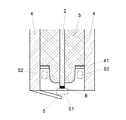
- the spark plug 1 of the present embodiment includes a center electrode 2, an insulator 3, a metal shell 4, and a ground electrode 5.
- the center electrode 2 is a cylindrical conductor and is made of, for example, iron nickel, and transmits a pulse voltage inside thereof, while transmitting a microwave on its outer surface.
- the pulse voltage is generated by an ignition coil (not shown), and this is input to the center electrode 2 from a terminal portion (not shown) of the ignition plug 1.
- the microwave is generated by an external microwave oscillator (not shown) and is also input to the center electrode 2 from the terminal portion.
- the insulator 3 is a cylindrical insulator (for example, formed of ceramic), and a shaft hole into which the center electrode 2 is fitted is formed.
- the metal shell 4 is formed of a cylindrical metal conductor formed so as to surround the insulator 3.
- the discharge electrode 6 is joined to the tip of the center electrode 2.
- One end of the ground electrode 5 is joined to the tip of the metal shell 4, while the other end faces the discharge electrode 6.
- the outer peripheral surface on the tip side of the insulator 3 is separated from the inner peripheral surface of the metal shell 4.
- An annular projecting member 41 is formed on the inner periphery of the metallic shell 4 at a position away from the tip end surface of the metallic shell 4 by about one eighth wavelength to one quarter wavelength of the microwave (hereinafter referred to as “the annular projection member 41”). Then, the wavelength simply means the wavelength of the input microwave unless otherwise specified).
- the spark plug 1 has the effect of preventing wear of the tip (discharge part) of the center electrode 2 by forming the protruding member 41. The reason will be described below.
- spark discharge spark discharge
- the plasma in the space S1 is expanded by radiating microwaves to the space S1 from the outer peripheral tip of the center electrode 2. It is ideal that all the microwaves radiated to the space S1 are absorbed by the plasma, but if the plasma density becomes too high, some microwaves are reflected without being absorbed by the plasma. The microwave reflected by the plasma returns to the rear end side (supply side) through the center electrode 2, the metal shell 4, and the insulator 3, and becomes unnecessary power. Furthermore, the plasma generated in the space S1 is converted into thermal plasma, and the tip of the center electrode 2 is worn.
- an annular projecting member 41 is provided on the inner peripheral surface of the metal shell 4.
- the protruding member 41 acts as a kind of stub tuner and prevents the microwave from flowing backward to the supply side. Some of the microwaves incident on the protruding member 41 are directed again toward the distal end side, and cancel each other with the microwaves flowing backward from the distal end surface of the metal shell 4. As a result, the microwave reflected by the plasma in the space S1 can be prevented from flowing back to the supply side.
- the protruding member 41 is provided at a position of a quarter wavelength of the microwave from the front end surface of the metal shell 4.
- the protruding member 41 is provided at a position shorter than a quarter wavelength.
- it is provided at the position of 1/8 wavelength of the microwave from the front end surface of the metal shell 4 it does not function as a stub tuner. Therefore, it is provided at a position of 1/8 wavelength or more from the front surface of the metal shell 4. Is preferred.
- the microwave when the microwave is incident on the protruding member 41, the plasma in the space S1 is guided to the annular space S2 surrounded by the protruding member 41, the insulator 3, and the metal shell 4.
- the plasma in the space S1 is guided to the annular space S2 surrounded by the protruding member 41, the insulator 3, and the metal shell 4.
- the protruding member 41 is provided at a position less than one-eighth wavelength from the front end surface of the metal shell 4, the distance between the space S1 and the space S2 becomes too short. An excessive increase in density cannot be suppressed.
- the protruding member 41 is provided at a position exceeding a quarter wavelength from the distal end surface of the metal shell 4, it may be necessary to change the shape of the distal end portion of the insulator 3. This is because, in ordinary spark plugs, the length of the portion spaced from the metal shell 4 on the tip side of the insulator 3 is less than a quarter wavelength.
- the metal shell 4 is an example of the cylindrical conductor of the present invention, but a dedicated cylindrical conductor may be provided as a microwave return line, for example.
Abstract
Description
2 中心電極
3 絶縁碍子
4 主体金具
5 接地電極
6 放電電極
Claims (5)
- 中心電極と、
中心電極が嵌め込まれる軸孔が形成された絶縁碍子と、
中心電極との間に火花放電が生じる空間を形成する接地電極と、
絶縁碍子の外周に設けられた筒状導体を備え、
火花放電のためのパルス電圧及び火花放電にエネルギとして供給される電磁波が、中心電極に給電される点火プラグであって、
筒状導体の筒状導体内周には円環状部材が、筒状導体の先端部端面から前記電磁波の8分の1波長から4分の1波長の範囲内の位置に形成されていることを特徴とする点火プラグ。 - 前記筒状導体が主体金具であることを特徴とする請求項1に記載の点火プラグ。
- 前記円環状部材の内周面が、絶縁碍子の外周面に接することを特徴とする請求項1に記載の点火プラグ。
- 請求項1に記載の点火プラグを備えた点火装置であって、
該点火装置は、
パルス電圧を中心電極に給電することにより、前記中心電極と接地電極の間の空間である第1空間に火花放電を生じさせて該第1空間にプラズマを生じさせ、電磁波を中心電極に給電することにより、前記第1空間のプラズマを拡大させる制御装置を有し、
第1空間にプラズマが形成された後に電磁波を中心電極に給電したとき、中心電極の先端から第1空間に放射された電磁波のうち、前記第1空間に形成されたプラズマで反射した電磁波の少なくとも一部が、前記筒状導体を介して前記円環状の突起部へ入射するように前記点火プラグが形成されたことを特徴とする点火装置。 - 前記電磁波が前記円環状の突起部に入射したとき、前記第1空間に形成されたプラズマの少なくとも一部が、前記筒状導体の先端部と絶縁碍子の外周の間の空間である第2空間に移動することにより、前記第1空間のプラズマが熱プラズマ化されることを防止するように前記点火プラグが形成されたことを特徴とする請求項4記載の点火装置。
Priority Applications (3)
| Application Number | Priority Date | Filing Date | Title |
|---|---|---|---|
| US15/772,303 US20180313317A1 (en) | 2015-10-30 | 2016-10-26 | Ignition plug and ignition device |
| JP2017547908A JPWO2017073760A1 (ja) | 2015-10-30 | 2016-10-28 | 点火プラグ、及び点火装置 |
| EP16859988.4A EP3370313A4 (en) | 2015-10-30 | 2016-10-28 | Ignition plug and ignition device |
Applications Claiming Priority (2)
| Application Number | Priority Date | Filing Date | Title |
|---|---|---|---|
| JP2015-214431 | 2015-10-30 | ||
| JP2015214431 | 2015-10-30 |
Publications (1)
| Publication Number | Publication Date |
|---|---|
| WO2017073760A1 true WO2017073760A1 (ja) | 2017-05-04 |
Family
ID=58631656
Family Applications (1)
| Application Number | Title | Priority Date | Filing Date |
|---|---|---|---|
| PCT/JP2016/082148 WO2017073760A1 (ja) | 2015-10-30 | 2016-10-28 | 点火プラグ、及び点火装置 |
Country Status (4)
| Country | Link |
|---|---|
| US (1) | US20180313317A1 (ja) |
| EP (1) | EP3370313A4 (ja) |
| JP (1) | JPWO2017073760A1 (ja) |
| WO (1) | WO2017073760A1 (ja) |
Cited By (1)
| Publication number | Priority date | Publication date | Assignee | Title |
|---|---|---|---|---|
| US20230070763A1 (en) * | 2021-09-09 | 2023-03-09 | Hyundai Motor Company | Multi-ignition coil control system |
Citations (2)
| Publication number | Priority date | Publication date | Assignee | Title |
|---|---|---|---|---|
| WO2014203873A1 (ja) * | 2013-06-18 | 2014-12-24 | イマジニアリング株式会社 | 点火プラグ及びプラズマ発生装置 |
| WO2015163366A1 (ja) * | 2014-04-22 | 2015-10-29 | イマジニアリング株式会社 | 点火プラグ及びソケット |
Family Cites Families (3)
| Publication number | Priority date | Publication date | Assignee | Title |
|---|---|---|---|---|
| WO2009008520A1 (ja) * | 2007-07-12 | 2009-01-15 | Imagineering, Inc. | 点火プラグ及び分析装置 |
| EP2180176B1 (en) * | 2007-07-12 | 2016-12-14 | Imagineering, Inc. | Ignition or plasma generation device |
| EP2743494B1 (en) * | 2011-07-16 | 2016-09-07 | Imagineering, Inc. | Internal combustion engine, and plasma generating device |
-
2016
- 2016-10-26 US US15/772,303 patent/US20180313317A1/en not_active Abandoned
- 2016-10-28 JP JP2017547908A patent/JPWO2017073760A1/ja not_active Ceased
- 2016-10-28 WO PCT/JP2016/082148 patent/WO2017073760A1/ja active Application Filing
- 2016-10-28 EP EP16859988.4A patent/EP3370313A4/en not_active Withdrawn
Patent Citations (2)
| Publication number | Priority date | Publication date | Assignee | Title |
|---|---|---|---|---|
| WO2014203873A1 (ja) * | 2013-06-18 | 2014-12-24 | イマジニアリング株式会社 | 点火プラグ及びプラズマ発生装置 |
| WO2015163366A1 (ja) * | 2014-04-22 | 2015-10-29 | イマジニアリング株式会社 | 点火プラグ及びソケット |
Non-Patent Citations (1)
| Title |
|---|
| See also references of EP3370313A4 * |
Cited By (2)
| Publication number | Priority date | Publication date | Assignee | Title |
|---|---|---|---|---|
| US20230070763A1 (en) * | 2021-09-09 | 2023-03-09 | Hyundai Motor Company | Multi-ignition coil control system |
| US11784466B2 (en) * | 2021-09-09 | 2023-10-10 | Hyundai Motor Company | Multi-ignition coil control system |
Also Published As
| Publication number | Publication date |
|---|---|
| US20180313317A1 (en) | 2018-11-01 |
| EP3370313A4 (en) | 2018-10-31 |
| JPWO2017073760A1 (ja) | 2018-08-23 |
| EP3370313A1 (en) | 2018-09-05 |
Similar Documents
| Publication | Publication Date | Title |
|---|---|---|
| JP5632993B2 (ja) | 混合器、整合器、点火ユニット、及びプラズマ生成器 | |
| JP5320474B2 (ja) | 点火システム及び点火プラグ | |
| US9638158B2 (en) | Spark plug and plasma generating device | |
| JP6387490B2 (ja) | 点火プラグ及びプラズマ発生装置 | |
| WO2015163366A1 (ja) | 点火プラグ及びソケット | |
| WO2017073760A1 (ja) | 点火プラグ、及び点火装置 | |
| JP6191030B2 (ja) | プラズマ生成装置、及び内燃機関 | |
| JP5936101B2 (ja) | 点火システム及びその制御方法 | |
| WO2016108283A1 (ja) | 点火システム、及び内燃機関 | |
| WO2017002899A1 (ja) | 点火プラグ | |
| WO2016125857A1 (ja) | 点火プラグ | |
| WO2016013615A1 (ja) | 点火プラグ | |
| JP2010249029A (ja) | 火花点火式内燃機関 | |
| JP6715600B2 (ja) | 内燃機関用の点火プラグ | |
| WO2016088899A2 (ja) | 点火装置、点火システム、及びコネクタ | |
| WO2016129504A1 (ja) | 内燃機関用の点火プラグ | |
| WO2018225169A1 (ja) | 点火装置 | |
| JP6685516B2 (ja) | 内燃機関 | |
| JP2022511889A (ja) | 点火装置及び原動機製品 | |
| JP2017203449A (ja) | 点火装置 | |
| JP2010249028A (ja) | 火花点火式内燃機関 |
Legal Events
| Date | Code | Title | Description |
|---|---|---|---|
| 121 | Ep: the epo has been informed by wipo that ep was designated in this application |
Ref document number: 16859988 Country of ref document: EP Kind code of ref document: A1 |
|
| ENP | Entry into the national phase |
Ref document number: 2017547908 Country of ref document: JP Kind code of ref document: A |
|
| WWE | Wipo information: entry into national phase |
Ref document number: 15772303 Country of ref document: US |
|
| NENP | Non-entry into the national phase |
Ref country code: DE |
|
| WWE | Wipo information: entry into national phase |
Ref document number: 2016859988 Country of ref document: EP |