WO2016013615A1 - 点火プラグ - Google Patents
点火プラグ Download PDFInfo
- Publication number
- WO2016013615A1 WO2016013615A1 PCT/JP2015/070972 JP2015070972W WO2016013615A1 WO 2016013615 A1 WO2016013615 A1 WO 2016013615A1 JP 2015070972 W JP2015070972 W JP 2015070972W WO 2016013615 A1 WO2016013615 A1 WO 2016013615A1
- Authority
- WO
- WIPO (PCT)
- Prior art keywords
- center electrode
- electrode
- conductor
- rear end
- cylinder
- Prior art date
Links
Images


Classifications
-
- H—ELECTRICITY
- H01—ELECTRIC ELEMENTS
- H01T—SPARK GAPS; OVERVOLTAGE ARRESTERS USING SPARK GAPS; SPARKING PLUGS; CORONA DEVICES; GENERATING IONS TO BE INTRODUCED INTO NON-ENCLOSED GASES
- H01T13/00—Sparking plugs
- H01T13/20—Sparking plugs characterised by features of the electrodes or insulation
- H01T13/34—Sparking plugs characterised by features of the electrodes or insulation characterised by the mounting of electrodes in insulation, e.g. by embedding
-
- H—ELECTRICITY
- H01—ELECTRIC ELEMENTS
- H01T—SPARK GAPS; OVERVOLTAGE ARRESTERS USING SPARK GAPS; SPARKING PLUGS; CORONA DEVICES; GENERATING IONS TO BE INTRODUCED INTO NON-ENCLOSED GASES
- H01T13/00—Sparking plugs
- H01T13/40—Sparking plugs structurally combined with other devices
Definitions
- the present invention relates to a spark plug for irradiating a high voltage for spark discharge and an electromagnetic wave supplied as energy to the spark discharge.
- a plasma generating apparatus has been developed that creates local plasma using spark plug discharge and expands this plasma using electromagnetic waves (for example, see Patent Document 1).
- a mixer having a mixing circuit for mixing a discharge current for spark discharge (energy for discharge) and energy of electromagnetic waves from an electromagnetic wave generator (hereinafter referred to as electromagnetic wave oscillator) is provided.
- the mixer is connected to a connection terminal portion serving as an input terminal of the spark plug.
- the high voltage (discharge current) for spark discharge and the electromagnetic wave are fed to the spark plug through the same transmission line (electric circuit). Therefore, the center electrode of the spark plug serves as both a spark discharge electrode and an electromagnetic wave irradiation antenna.
- the center electrode of a general spark plug used in this plasma generator (hereinafter collectively referred to as the center electrode from the terminal portion connected to the ignition coil to the tip portion forming the discharge gap between the ground electrode)
- the same shall apply hereinafter) is usually made of an iron-based alloy except for the tip. Therefore, the electromagnetic wave supplied from the electromagnetic wave oscillator flows on the surface of the center electrode, but it has a large power loss because it is mainly composed of iron with high magnetic permeability and has a built-in resistor inside. Therefore, the electromagnetic wave oscillator could not be miniaturized in order to perform sufficient electromagnetic wave irradiation.
- the discharge current and electromagnetic wave for spark discharge are both output from the tip of the center electrode. Therefore, the electric field strength generated by the discharge current and the electromagnetic wave between the tip of the center electrode and the ground electrode is highest at the axial core portion of the center electrode. For this reason, the electric field strength generated by the discharge current and the electromagnetic wave is superimposed, and the axial center of the center electrode has the highest temperature, and the tip end portion of the center electrode is easily melted.
- the present inventors use a conductor tube configured to cover the center electrode, not the center electrode, as an electromagnetic wave transmission path, thereby reducing power loss and reducing the electric field strength to the center electrode.
- a spark plug that prevents the tip portion of the center electrode from being melted without being superimposed on the axis (for example, Patent Documents 2 to 3).
- a typical spark plug is a resistor that is inserted between a tip center electrode having an electrode tip portion in an axial hole of an insulator and a rear end center electrode having a terminal portion that receives power from the outside, and is filled between the two. It seals by heating with body powder, and fixes a center electrode in an insulator.
- the center electrode of the spark plug proposed by the present inventors consists of a rear end portion having a terminal portion that receives power from the outside, and a front end portion having a smaller diameter than the rear end portion and an electrode tip portion,
- An insulating cylinder having a conductor tube attached to the outer peripheral surface is attached to the tip, and the outer peripheral surface of the end contacting the center electrode rear end of the conductor tube is joined to the center electrode rear end.
- the anti-joining end of the conductor cylinder is provided with an anti-extraction ring on the inner peripheral surface to prevent the internal insulating cylinder from falling off.
- gas may remain inside the spark plug, for example, in the gap between the outer peripheral surface of the insulating cylinder and the inner peripheral surface of the conductor cylinder. Due to the structure, if gas remains in this gap, there is no discharge path. When attached to an internal combustion engine, the remaining gas expands as the temperature rises, causing problems such as disconnection of the conductor tube and damage to the insulating tube.
- JP 2009-036198 A Japanese Patent Application No. 2013-160862 Japanese Patent Application No. 2014-088631
- the present invention has been made based on the circumstances as described above, and its purpose is to provide a spark plug in which an insulating cylinder having a conductor cylinder attached to the outer peripheral surface is attached to the tip of the center electrode. It is an object of the present invention to provide a spark plug capable of avoiding problems caused by the gas remaining in the gas.
- the first invention made in order to solve the above-described problems is a center electrode that generates a spark discharge by power feeding from the outside with respect to the ground electrode, An insulator having a shaft hole into which the center electrode is fitted, and The center electrode is composed of a rear end portion having a terminal portion that receives power from the outside, and a front end portion having an electrode tip portion having a smaller diameter than the rear end portion, At the tip, an insulating cylinder having a conductor cylinder attached to the outer peripheral surface is attached, The conductor tube is provided with a ring for preventing the insulation tube from coming off on the inner peripheral surface of one end, and the other end is joined to the rear end of the center electrode, It is a spark plug provided with a gas discharge mechanism for discharging the gas remaining inside to the outside.
- the spark plug of the present invention is provided with a gas discharge mechanism that discharges the gas remaining in the gap between the conductor tube and the insulating tube attached to the inside of the spark plug, for example, the outer peripheral surface of the center electrode. Even if it is used by attaching to the conductor, the conductor tube is not disconnected or the insulating tube is not damaged.
- the gas discharge mechanism can be a groove formed on a contact surface with the insulating cylinder of the escape preventing ring.
- the second invention made in order to solve the above-mentioned problem, a center electrode that generates a spark discharge by power feeding from the outside with the ground electrode, An insulator having a shaft hole into which the center electrode is fitted, and The center electrode is composed of a rear end portion having a terminal portion that receives power from the outside, and a front end portion having an electrode tip portion having a smaller diameter than the rear end portion, At the tip, an insulating cylinder having a conductor cylinder attached to the outer peripheral surface is attached, Provide a step portion for preventing the insulation tube from coming off at the open end of the shaft hole on the ground electrode side, The conductor tube is joined to the rear end portion of the center electrode at the end on the anti-ground electrode side, It is a spark plug provided with a gas discharge mechanism for discharging the gas remaining inside to the outside.
- the spark plug of the present invention discharges the gas remaining in the gap between the conductor cylinder and the insulating cylinder attached to the inside of the spark plug, for example, the outer peripheral surface of the center electrode, to the outside. Since the mechanism is provided, the conductor cylinder is not disconnected or the insulating cylinder is not damaged even if it is attached to an internal combustion engine. In addition, since the stepped portion for preventing the insulation tube from coming off is provided at the open end portion of the shaft hole of the insulator on the ground electrode side, the open end portion of the conductor tube is not exposed to the combustion chamber of the internal combustion engine. Carbon does not adhere to the open end of the tube, and electromagnetic wave irradiation failure and abnormal ignition between the electrode tip portion do not occur.
- the gas discharge mechanism can be a groove formed on the contact surface of the stepped portion with the insulating tube. By forming the groove in the contact surface of the stepped portion with the insulating tube, the gas remaining inside can be reliably discharged.
- the gas discharge mechanism can be a gap formed at the junction between the conductor tube and the rear end of the center electrode. Normally, when the whole contact area (around the circumference) of the rear end portion of the center electrode and the conductor tube is welded, a gap is generated at a place where spot welding is not performed by spot welding or the like at a plurality of positions on the circumference. The gas remaining inside is discharged from the gap. Further, by providing a notch at the end of the conductor tube that contacts the rear end of the center electrode, gas can be discharged from the notch even if the entire circumference is welded.
- the conductor tube can be fitted and joined to the rear end portion of the center electrode, and in this case, a groove portion is formed in a portion where the conductor tube of the rear end portion of the center electrode is fitted or a flat portion is formed. To form a gap.
- a conductor is a metal material such as iron, silver, copper, gold, aluminum, tungsten, molybdenum, titanium, zirconium, kovar, niobium, Refers to tantalum, bismuth, lead, tin, or alloys based on these (for example, stainless steel) or composite materials thereof.
- Insulators Insulation cylinders, insulators, etc. (including dielectrics)) It refers to ceramics based on materials, alumina (AL 2 O 3 ) and the like.
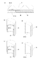
- FIG. 4C is a cross-sectional perspective view of a partially cutout in which a groove is provided on the contact surface of the ring with the insulating cylinder, and FIG.
- the perspective view (d) is a cross-sectional perspective view of a notch provided with a groove on the contact surface of the insulating cylinder with the retaining ring, and (c) is a protrusion on the contacting surface of the insulating cylinder with the retaining ring. It is a cross-sectional perspective view of the partially notched which provided.
- the ignition plug which concerns on 2nd Embodiment is shown, (a) is a partial cross section figure, (b) is a cross-sectional perspective view of the notch which provided the groove part in the contact surface with the insulation cylinder of the level
- FIG. 4C is a cross-sectional perspective view of the partially cutout provided
- FIG. 5C is a cross-sectional perspective view of the partially cutout provided with a protrusion on the contact surface with the stepped portion of the insulating cylinder.
- the front view of the partial cross section of the spark plug which concerns on 3rd Embodiment is shown.
- the enlarged view of the partial cross section of the spark plug which concerns on 3rd Embodiment is shown.
- -Spark plug- Embodiment 1 is a spark plug according to the first invention.
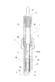
- FIG. 1 shows a spark plug according to the first embodiment.
- the spark plug 1 includes a center electrode 2 that generates a spark discharge by external power supply to the ground electrode 5 and an insulator 3 in which a shaft hole 30 into which the center electrode 2 is fitted is formed.
- 2 includes a rear end portion 21 provided with a terminal portion 20 that receives power from the outside, and a front end portion 22 having a smaller diameter than the rear end portion 21 and provided with an electrode tip portion.
- An insulating cylinder 2B having a conductor cylinder 2A is attached.
- the insulator 3 is inserted and fixed in the hollow metal shell 4.
- the ground electrode 5 extends from the end face of the metal shell 4.
- the conductor cylinder 2A is provided with a ring 2C for preventing the insulation cylinder from coming off on the inner peripheral surface of one end, and the outer peripheral surface of the other end is joined to the rear end portion 21 of the center electrode 2.
- the spark plug 1 includes a gas discharge mechanism 6 that discharges the gas remaining in the gap between the inner peripheral surface of the conductor tube 2A and the outer peripheral surface of the insulating tube 2B to the outside.
- the gas discharge mechanism 6 uses a gap formed at a joint portion between the conductor tube 2A and the rear end portion of the center electrode 2.
- a prevention ring 2C is disposed on the inner peripheral surface of one end of the conductor cylinder 2A as prevention of the insulation cylinder 2B attached to the tip 22 from coming off. Therefore, it is necessary to firmly join the multi-end side of the conductor tube 2A to the rear end portion 21 of the center electrode 2 because the end surface of the insulating tube 2B is held in contact therewith.
- the gas discharge mechanism 6 can be a concavo-convex portion formed on the contact surface of the escape preventing ring 2C with the insulating cylinder 2B.
- a groove (concave portion) 6B (see FIG. 2 (b)) and a projecting portion (convex portion) 6C (see FIG. 2 (c)) are formed on the contact surface of the prevention ring 2C with the insulating cylinder 2B or insulated.
- a groove (concave portion) 6D see FIG. 2 (d)
- a protrusion (convex portion) 6E see FIG. 2 (e)
- a path for exhausting the gas remaining inside (in this case, the gap between the inner peripheral surface of the conductor tube 2A and the outer peripheral surface of the insulating tube 2B) to the outside is provided, and remains as the temperature rises. Even if the gas expands, the joining of the conductor tube 2A does not come off and the insulating tube 2B is not damaged. Further, a configuration is provided such that a predetermined gap is generated at the contact portion between the rear end portion 21 of the center electrode 2 and the insulating tube 2B shown in FIG. 2A (a notch portion is provided at the contact portion of the insulating tube 2B). ), The gas remaining in the gap between the outer peripheral surface of the distal end portion 22 of the center electrode 2 and the inner peripheral surface of the insulating cylinder 2B can be discharged to the outside.
- the conductor tube 2A attached to the insulating tube 2B is electrically connected to the terminal portion 20 that receives power from the outside via the rear end portion 21 of the center electrode.
- the high voltage for the spark discharge and the electromagnetic wave supplied as energy to the spark discharge prevent the mixer circuit (the high voltage (discharge current) for the spark discharge and the electromagnetic wave from flowing back to the respective supply sources.
- Power is supplied to the terminal unit 20 from a secondary electrode side of an ignition coil (not shown) and an electromagnetic wave oscillator (not shown) via a mixer device (not shown) provided with a circuit.
- the end of the conductor tube 2A on the side of the ground electrode 5 is annular, and from the tip 22 of the pointed center electrode 2 (the electrode tip formed at the tip of the tip 22).
- the electric field strength is low.
- the tip end portion of the center electrode 2 protrudes from the end portion on the ground electrode side of the conductor tube 2A, the distance from the ground electrode 5 is shorter from the tip end portion 22 of the center electrode 2.
- the insulator 3 is formed by a known method, for example, an alumina powder is formed by a hydrostatic press with ceramics based on alumina (AL 2 O 3 ) having high insulation and heat and corrosion resistance, and a grinding device, a grindstone, etc. Then, the insulator 3 is manufactured by firing at around 1600 ° C.
- a high melting point and oxidation-resistant noble metal for example, platinum alloy or iridium
- platinum alloy or iridium for example, platinum alloy or iridium
- the conductor cylinder 2A attached to the outer peripheral surface of the insulating cylinder 2B is not particularly limited as long as it is a thin cylindrical metal conductor having a thickness of about 0.04 mm to 0.2 mm, preferably about 0.06 mm to 0.1 mm.
- the insulating cylinder 2B is preferably made of ceramics based on alumina (AL 2 O 3 ) or the like having high insulation properties and heat and corrosion resistance.
- the terminal portion 20 receives power from the ignition coil, is inserted into the shaft hole 30 and is electrically connected to the rear end portion 21 of the center electrode 2.
- the metal shell 4 is a substantially cylindrical metal case.
- the metal shell 4 supports the outer periphery of the insulator 3 and accommodates the insulator 3.
- the inner peripheral surface of the front end portion of the metal shell 4 is separated from the outer peripheral surface of the front end portion of the insulator 3 with a gap.
- a male screw portion 41 is formed as an attachment structure for attachment to the internal combustion engine.
- the spark plug 1 is screwed and fixed to the cylinder head by screwing the male screw portion 41 of the metal shell 4 into the female screw portion (not shown) of the plug hole of the cylinder head.
- a wrench fitting portion 40 into which a plug wrench is fitted is formed on the upper part of the metal shell 4.
- powdery talc (talc) is filled as a sealing member, and the end part is crimped.
- the ground electrode 5 forms a discharge gap in which spark discharge occurs with the center electrode 2.
- the ground electrode 5 includes a ground electrode body 5b and a ground electrode tip 5a.
- the ground electrode body 5b is a curved plate-like conductor. One end side of the ground electrode main body 5 b is joined to the front end surface of the metal shell 4.
- the ground electrode body 5b extends from the front end surface of the metal shell 4 along the axis of the spark plug 1 and bends approximately 90 ° inward, and the front end side where the ground electrode tip portion 5a is provided is the front end 22 of the center electrode 2. It faces the electrode tip portion provided in the.
- the assembly of the center electrode 2 (the rear end portion 21 and the front end portion 22), the insulating tube 2B, the conductor tube 2A, and the terminal portion 20 is not particularly limited, but in the present embodiment, it is shown in FIG.
- tip part 22 is inserted in the attachment hole formed in the edge part of the rear-end part 21 of the center electrode 2, and it joins by joining means, such as brazing and laser welding.
- the insulating cylinder 2B is attached to the front end portion 22 of the center electrode 2, and the conductor cylinder 2A having an inner diameter substantially the same as the outer diameter of the rear end portion 21 of the center electrode is attached.
- the end face of the insulating cylinder 2B is brought into contact with the inner end face of the escape preventing ring 2C disposed at one end of the conductor cylinder 2A. Thereafter, the other end of the conductor tube 2A and the rear end portion 21 of the center electrode 2 are joined by a joining means such as spot welding.
- the insulating cylinder 2B may be attached to the distal end portion 22 of the center electrode 2 while being attached to the conductor cylinder 2A.
- a male screw is engraved in the vicinity of the terminal portion 20 at the outer peripheral portion of the rear end portion 21 of the center electrode 2 inserted into the shaft hole 30, and a female screw is engraved at a corresponding position on the inner surface of the shaft hole 30 of the insulator 3.
- the male screw of the terminal portion 20 is screwed and fixed to the female screw of the shaft hole 30.
- the center electrode 2, the conductor tube 2 ⁇ / b> A, the insulating tube 2 ⁇ / b> B, and the terminal unit 20 are connected to the insulator 3 by using an appropriate joining means such as a ceramic adhesive without engraving screws in the shaft hole 30 and the terminal unit 20. It can also be joined. Thereafter, the insulator 3 including the conductor cylinder 2A, the center electrode 2, the insulating cylinder 2B, and the terminal portion 20 is attached to the metal shell 4 to complete the spark plug 1.
- the spark plug 1 has a high voltage for spark discharge fed from the terminal portion 20 flowing through the axial center of the terminal portion 20 and the center electrode 2, and the electrode tip portion of the tip portion 22 of the center electrode 2 Spark discharge (spark discharge) is generated between the ground electrode tip portion 5a, that is, in the discharge gap.
- the electromagnetic wave (microwave) supplied from the terminal portion 20 as energy to the spark discharge has a characteristic of flowing on the surface of the conductor and the dielectric, and therefore flows on the surface of the rear end portion 21 and the conductor tube 2A, and the conductor tube 2A.
- the peak portion of the electric field strength of the irradiated electromagnetic wave is shifted from the axis of the center electrode 2 and deviates from the peak portion of the electric field strength due to the discharge current.
- the spark plug 1 of the present embodiment is the spark plug 1 having the tip 22 of the center electrode 2 and the insulating cylinder 2B having the conductor cylinder 2A mounted on the outer peripheral surface, the inside, for example, the outer peripheral surface of the insulating cylinder 2B is provided. And problems caused by the gas remaining in the gap between the inner circumferential surface of the conductor cylinder 2A can be avoided.
- the second embodiment is a spark plug according to the second invention.
- This spark plug differs from the spark plug of the first embodiment in the mounting structure of the conductor cylinder 2A, the insulating cylinder 2B, and the insulator 3.
- FIG. 3 shows a spark plug according to the second embodiment.
- the spark plug 1 includes an insulator 3 in which a center electrode 2 including a terminal portion 20 and an electrode tip portion that receive power from the outside and a shaft hole 30 into which the center electrode 2 is fitted are formed.
- spark discharge occurs between the metal shell 4 disposed so as to surround the insulator 3 and the electrode tip portion of the tip 22 of the center electrode 2 extending from the end surface of the metal shell 4.
- a ground electrode 5 for forming a discharge gap.
- the center electrode 2 includes a front end portion 22 having an electrode tip portion and a rear end portion 21 having a terminal portion 20.
- the center electrode 2 includes a rear end portion 21 having a terminal portion 20 that receives power from the outside, and a tip portion 22 having a smaller diameter than the rear end portion 21 and having an electrode tip portion.
- the insulating cylinder 2B having the conductor cylinder 2A mounted on the surface is mounted, and the insulating cylinder 2B (and the conductor cylinder 2A) is prevented from coming off at the open end of the shaft hole 30 of the insulator 3 on the ground electrode 5 side. 31 is provided so that the end on the side of the anti-ground electrode is joined to the rear end 21 of the center electrode 2 in the conductor cylinder 2A.
- the gas discharge mechanism 6 can be a concavo-convex portion formed on the contact surface of the step portion 31 with the insulating cylinder 2B as shown in FIGS. 3 (b) to 3 (e).
- Grooves (concave portions) 6B (see FIG. 3 (b)) and projections (convex portions) 6C (see FIG. 3 (c)) are formed on the contact surface of the step portion 31 with the insulating tube 2B, or the insulating tube 2B.
- the conductor tube 2A When attached, it remains in the interior (in this case, the gap between the inner peripheral surface of the conductor tube 2A and the outer peripheral surface of the insulating tube 2B and the gap between the outer peripheral surface of the tip 22 of the center electrode 2 and the inner peripheral surface of the conductor tube 2A). Therefore, even if the remaining gas expands as the temperature rises, the conductor tube 2A is not disconnected and the insulating tube 2B is not damaged.
- the groove (concave) 6D and the protrusion (convex) 6E are formed in the insulating cylinder 2B, it is preferable to form the groove (concave) and the protrusion (convex) at a corresponding portion of the conductor cylinder 2A.
- the outer peripheral surface of the front end portion 22 of the center electrode 2 and the conductor tube are configured so that a predetermined gap is formed at a contact portion between the front end portion 22 of the center electrode 2 and the insulating tube 2B shown in FIG.
- the gas remaining in the gap on the inner peripheral surface of 2A can be discharged to the outside.
- the step portion 31 plays a role of insulation protection between the end surface of the conductor tube 2A and the ground electrode 5, and effectively prevents a spark discharge from being generated from the conductor tube 2A.
- the end face of the conductor cylinder 2A is not exposed to the combustion chamber, abnormal discharge due to adhesion of combustion soot is prevented.
- the structure for locking the insulator 3 to the metal shell 4 has a corner R of the insulator 3 so that the stress can be effectively distributed so as to withstand the combustion pressure. It is preferable to take a large shape.
- spark discharge is generated between the electrode tip portion of the portion 22 and the ground electrode tip portion 5a, that is, in the discharge gap. Since the electromagnetic wave (microwave) supplied as energy to the spark discharge has a characteristic of flowing on the surface of the conductor and the dielectric, it flows on the surface of the terminal portion 20, the rear end portion 21 and the conductor tube 2A, and the conductor tube 2A. Irradiated from the end surface of the ground electrode toward the ground electrode 5 side (combustion chamber side) in an annular shape.
- the irradiated electromagnetic wave is supplied as energy to the discharge plasma generated in the discharge gap formed between the center electrode 2 and the ground electrode 5, and the plasma is maintained and expanded.
- the gas inside the gas discharge mechanism 6 is discharged, and the joining of the conductor tube 2A or the insulating tube 2B may be damaged due to the temperature rise. Absent.
- the peak portion of the electric field strength of the irradiated electromagnetic wave is shifted from the axis of the center electrode 2 and deviates from the peak portion of the electric field strength due to the discharge current. As a result, it is possible to prevent a high temperature at the shaft core portion of the center electrode 2 and to effectively prevent the electrode tip portion of the tip portion 22 of the center electrode 2 from being melted.
- the spark plug according to the present embodiment is the same as the spark plug 1 in which the insulating tube 2B with the conductor tube 2A mounted on the outer peripheral surface is attached to the tip portion 22 of the center electrode 2.
- the step portion 31 of the insulator 3 plays a role of insulation protection, and effectively prevents a spark discharge from being generated from the conductor tube 2A.
- the third embodiment relates to a spark plug that can effectively prevent melting of the electrode tip portion of the tip portion 22 of the center electrode 2 and can diffuse the generated plasma widely in a direction away from the center electrode. is there.
- This spark plug differs from the spark plugs of the first and second embodiments in the shape of the tip of the insulator 3. The description of the same configuration as that of the first embodiment, such as the conductor cylinder 2A, the insulating cylinder 2B, the metal shell 4, and the ground electrode 5, is omitted.
- the spark plug 1 is formed with a center electrode 2 including a terminal portion 20 and an electrode tip portion that receive power from the outside, and a shaft hole 30 into which the center electrode 2 is fitted.
- the metal shell 4 disposed so as to surround the periphery of the insulator 3, and the electrode tip portion of the tip 22 of the center electrode 2 that extends from the end surface of the metal shell 4.
- a ground electrode 5 that forms a discharge gap in which spark discharge occurs.
- the center electrode 2 includes a front end portion 22 having an electrode tip portion and a rear end portion 21 having a terminal portion 20.
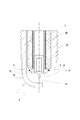
- the spark plug 1 is configured such that a chamfer 32 is applied to the corner of the tip of the insulator 3 on the ground electrode 5 side.
- the chamfering may be either 30 ° to 60 ° chamfering (including C chamfering) or R chamfering (two-dot chain line in FIG. 4), but in this embodiment, as shown in FIG.
- the position P of the surface of the insulator 3 where the distance from the tip of the cylinder 2A to the surface of the insulator 3 is the minimum (distance L in FIG. 4) is a position away from the tip of the center electrode 2. It has an inclined surface of about °.
- the tip of the conductor cylinder 2A abuts on the step portion 31 of the insulator 3, and the electric field strength is maximized because the minimum distance is directly below the tip of the conductor cylinder 2A. The diffusion effect of is reduced.
- the electromagnetic wave supplied from the electromagnetic wave transmitter is irradiated from the position P where the electric field strength is strongest, and the initial plasma generated in the vicinity of the discharge portion between the tip of the center electrode 2 and the ground electrode 5 is efficiently used. Can be expanded outwards well.
- the gas discharge mechanism 6 included in the first and second embodiments is not necessarily provided.
- a chamfer 32 is provided on the outer side of the tip of the insulator 3 on the ground electrode 5 side, and the place where the shortest distance is provided between the tip of the conductor tube 2A and the surface of the insulator 3 is the discharge part of the center electrode 2.
- the plasma generated by the discharge can be spread widely outward. Thereby, the high temperature in the axial center part of the center electrode 2 can be prevented, and the melting of the electrode tip portion of the tip portion 22 of the center electrode 2 can be effectively prevented.
- by chamfering the tip corners of the insulator 3 it is possible to prevent fires ignited by plasma due to discharge from hitting the insulator 3 and causing heat sink, and effectively preventing one of the causes of cooling loss. You can also.
- the high voltage for the spark discharge passes through the center of the center electrode, and the electromagnetic wave (microwave) supplied as energy to the spark discharge is generated from the end surface on the ground electrode side of the conductor tube. It is discharged in an annular shape so as to surround the axis of the center electrode, and it is possible to prevent high temperature in the axis of the center electrode and to greatly reduce electric loss, and gas remains inside.
- the internal gas is discharged from the gas discharge mechanism, and the conductor tube will not be disconnected or the insulating tube will not be damaged as the temperature rises. It can be suitably used for a plasma generator for supplying microwaves.
Landscapes
- Chemical & Material Sciences (AREA)
- Engineering & Computer Science (AREA)
- Combustion & Propulsion (AREA)
- Spark Plugs (AREA)
Abstract
【課題】中心電極の先端部に、外周面に導体筒を装着した絶縁筒を装着した点火プラグであっても、内部に残留する気体によって生じる不具合を回避することができる点火プラグを提供することであって、中心電極2は、外部からの給電を受ける端子部20を備えた後端部21と、後端部21より小径で電極チップ部を備えた先端部22とからなり、先端部22に、外周面に導体筒2Aを装着した絶縁筒2Bを装着し、導体筒2Aは、一端の内周面に絶縁筒2Bの抜け防止用リング2Cを配設するとともに、他端の外周面を中心電極2の後端部21と接合し、抜け防止用リング2Cの絶縁筒2Bとの当接面に形成した凹凸部からなる気体排出機構6を設け内部に残存する気体を外部に排出する。
Description
本発明は、火花放電のための高電圧及び火花放電にエネルギとして供給される電磁波を照射する点火プラグに関するものである。
従来から、点火プラグの放電を用いて局所的なプラズマを作り、このプラズマを電磁波(マイクロ波)により拡大させるプラズマ発生装置が開発されている(例えば、特許文献1参照)。このプラズマ発生装置においては、火花放電のための放電電流(放電のためのエネルギ)と電磁波発生装置(以下、電磁波発振器という)からの電磁波のエネルギとを混合する混合回路を備えた混合器が設けられており、この混合器は点火プラグの入力端子となる接続端子部に接続されている。これにより、火花放電のための高電圧(放電電流)と電磁波とは同じ伝送線路(電路)を通って点火プラグに給電される。従って、点火プラグの中心電極は、スパーク放電電極と電磁波照射用アンテナとを兼用する。
しかし、このプラズマ発生装置に使用される一般的な点火プラグの中心電極(以下、点火コイルと接続される端子部から接地電極との間で放電ギャップを形成する先端部分までを総称して中心電極とよぶ。以下同じ。)は、通常、先端部を除き、鉄を主成分とする合金から構成されている。そのため、電磁波発振器から供給される電磁波は、中心電極表面を流れることとなるが、透磁率の高い鉄を主成分とするため、また、内部に抵抗を内蔵しているため大きな電力損失を伴うこととなり、十分な電磁波の照射を行うためには電磁波発振器を小型化することができなかった。
また、火花放電のための放電電流及び電磁波は、共に中心電極の先端部分から出力される。そのため、中心電極先端と接地電極との間における、放電電流及び電磁波によって生じる電界強度は中心電極の軸芯部分が最も高くなる。このため、放電電流及び電磁波によって生じる電界強度が重畳されることとなり、中心電極の軸芯が最も高温となり、中心電極先端部分が溶損しやすいという不具合があった。
本発明者らは、かかる問題点に対処するため、電磁波の伝送路として、中心電極ではなく、中心電極を覆うように構成した導体筒を用い、電力損失を低減するとともに、電界強度が中心電極の軸心に重畳することなく、中心電極の先端部分か溶損することを防止する点火プラグを提案している(例えば、特許文献2~特許文献3)。
一般的な点火プラグは、絶縁碍子の軸穴に電極チップ部を備えた先端中心電極と外部からの給電を受ける端子部を備えた後端中心電極とを挿通し、両者の間に充填する抵抗体粉末とともに加熱することで封着し、絶縁碍子内に中心電極を固定する。一方、本発明者等が提案する点火プラグの中心電極は、外部からの給電を受ける端子部を備えた後端部と、後端部より小径で電極チップ部を備えた先端部とからなり、この先端部に、外周面に導体筒を装着した絶縁筒を装着して、導体筒の中心電極後端部と接する端部の外周面を中心電極後端部と接合するようにしている。導体筒の反接合端は内部の絶縁筒が抜け落ちることを防止するために内部周面に抜け防止用リングを配設している。
このため、点火プラグの内部、例えば、絶縁筒外周面と導体筒内周面との間隙に気体が残留する場合がある。構造上、この間隙に気体が残留すると排出経路がなく。内燃機関に取り付けて使用すると温度上昇に伴って残留する気体が膨張し、導体筒の接合が外れたり絶縁筒が損傷したりするといった問題があった。
本発明は、以上のような事情に基づいてなされたものであり、その目的は、中心電極の先端部に、外周面に導体筒を装着した絶縁筒を装着した点火プラグであっても、内部に残留する気体によって生じる不具合を回避することができる点火プラグを提供することである。
上記課題を解決するためになされた第1の発明は、接地電極との間で外部からの給電によって火花放電を生じさせる中心電極と、
該中心電極が嵌め込まれる軸孔が形成された絶縁碍子とを備え、
前記中心電極は外部からの給電を受ける端子部を備えた後端部と、該後端部より小径で電極チップ部を備えた先端部とからなり、
該先端部に、外周面に導体筒を装着した絶縁筒を装着し、
前記導体筒は、一端の内周面に絶縁筒の抜け防止用リングを配設するとともに、他端の端部を前記中心電極の後端部と接合し、
内部に残存する気体を外部に排出する気体排出機構を設けた点火プラグである。
該中心電極が嵌め込まれる軸孔が形成された絶縁碍子とを備え、
前記中心電極は外部からの給電を受ける端子部を備えた後端部と、該後端部より小径で電極チップ部を備えた先端部とからなり、
該先端部に、外周面に導体筒を装着した絶縁筒を装着し、
前記導体筒は、一端の内周面に絶縁筒の抜け防止用リングを配設するとともに、他端の端部を前記中心電極の後端部と接合し、
内部に残存する気体を外部に排出する気体排出機構を設けた点火プラグである。
本発明の点火プラグは、点火プラグの内部、例えば、中心電極の先端部外周面に装着する導体筒と絶縁筒との間隙に残存する気体を外部に排出する気体排出機構を設けたから、内燃機関に取り付けて使用しても、導体筒の接合が外れたり絶縁筒が損傷したりすることがない。
また、この場合において、前記気体排出機構は、前記抜け防止用リングの絶縁筒との当接面に形成した溝部とすることができる。抜け防止用リングの絶縁筒との当接面に溝部を形成することで、内部に残留する気体を確実に排出することができる。
上記課題を解決するためになされた第2の発明は、接地電極との間で外部からの給電によって火花放電を生じさせる中心電極と、
該中心電極が嵌め込まれる軸孔が形成された絶縁碍子とを備え、
前記中心電極は、外部からの給電を受ける端子部を備えた後端部と、該後端部より小径で電極チップ部を備えた先端部とからなり、
該先端部に、外周面に導体筒を装着した絶縁筒を装着し、
前記軸孔の接地電極側の解放端部に絶縁筒の抜けを防止し用の段差部を設け、
前記導体筒は、反接地電極側の端部を前記中心電極の後端部と接合し、
内部に残存する気体を外部に排出する気体排出機構を設けた点火プラグである。
該中心電極が嵌め込まれる軸孔が形成された絶縁碍子とを備え、
前記中心電極は、外部からの給電を受ける端子部を備えた後端部と、該後端部より小径で電極チップ部を備えた先端部とからなり、
該先端部に、外周面に導体筒を装着した絶縁筒を装着し、
前記軸孔の接地電極側の解放端部に絶縁筒の抜けを防止し用の段差部を設け、
前記導体筒は、反接地電極側の端部を前記中心電極の後端部と接合し、
内部に残存する気体を外部に排出する気体排出機構を設けた点火プラグである。
本発明の点火プラグは、第1の発明と同様、点火プラグの内部、例えば、中心電極の先端部外周面に装着する導体筒と絶縁筒との間隙に残存する気体を外部に排出する気体排出機構を設けたから、内燃機関に取り付けて使用しても、導体筒の接合が外れたり絶縁筒が損傷したりすることがない。また、絶縁碍子の軸孔の接地電極側の解放端部に絶縁筒の抜けを防止し用の段差部を設けたから、導体筒の解放端部が内燃機関の燃焼室に露出することがなく導体筒の解放端部にカーボンが付着することがなく電磁波の照射不良や電極チップ部との間での異常点火が生じない。
この場合において、前記気体排出機構は、前記段差部の絶縁筒との当接面に形成した溝部とすることができる。段差部の絶縁筒との当接面に溝部を形成することで、内部に残留する気体を確実に排出することができる。
また、これらの場合において、前記気体排出機構は、前記導体筒と中心電極の後端部との接合箇所に形成した隙間とすることができる。通常、中心電極の後端部と導体筒との接触箇所の全体(周上)を溶接するところ、周上の複数個所をスポット溶接等することでスポット溶接されていないところに隙間が生じ、かかる隙間から内部に残留する気体を排出する。また、中心電極の後端部と当接する導体筒の端部に切り欠き部を設けることで周上全体を溶接しても切り欠き部から気体を排出することができる。また、導体筒は中心電極の後端部に嵌入して接合することもでき、この場合、中心電極の後端部の導体筒が嵌入される部分に溝部を形成したり、平坦部を形成したりすることで隙間を形成することができる。
なお、本発明の用語として、導体(中心電極、端子部、導体筒等)というときは、金属材料、例えば鉄、銀、銅、金、アルミニウム、タングステン、モリブデン、チタン、ジルコニウム、コバール、ニオブ、タンタル、ビスマス、鉛、スズ又はこれらを主体とした合金(例えば、ステンレス鋼)若しくはこれらの複合材料等を指し、絶縁体(絶縁筒、絶縁碍子等(誘電体を含む))というときは、絶縁材料、アルミナ(AL2O3)等を基材とするセラミックス等を指す。
本発明によると、中心電極の先端部に、外周面に導体筒を装着した絶縁筒を装着した点火プラグであっても、内部、例えば、絶縁筒外周面と導体筒内周面との間隙に残留する気体によって生じる不具合を回避することができる。
以下、本発明の実施形態を図面に基づいて詳細に説明する。なお、以下の実施形態は、本質的に好ましい例示であって、本発明、その適用物、あるいはその用途の範囲を制限することを意図するものではない。
<実施形態1>
-点火プラグ-
本実施形態1は、本第1発明に係る点火プラグである。
-点火プラグ-
本実施形態1は、本第1発明に係る点火プラグである。
図1に本実施形態1の点火プラグを示す。この点火プラグ1は、接地電極5との間で外部からの給電によって火花放電を生じさせる中心電極2と、中心電極2が嵌め込まれる軸孔30が形成された絶縁碍子3とを備え、中心電極2は、外部からの給電を受ける端子部20を備えた後端部21と、後端部21より小径で電極チップ部を備えた先端部22とからなり、この先端部22に、外周面に導体筒2Aを装着した絶縁筒2Bが装着されている。絶縁碍子3は、中空の主体金具4に挿通され固定されている。接地電極5はこの主体金具4の端面から延設されている。導体筒2Aは、一端の内周面に絶縁筒の抜け防止用リング2Cを配設するとともに、他端の外周面を中心電極2の後端部21と接合するようにしている。
そして、当該点火プラグ1は、導体筒2Aの内周面と絶縁筒2Bの外周面との間隙に残存する気体を外部に排出する気体排出機構6を備えている。この気体排出機構6は、導体筒2Aと中心電極2の後端部との接合箇所に形成した隙間を利用する。本実施形態(第1の発明)に係る点火プラグ1は、先端部22に装着される絶縁筒2Bの抜け防止として、導体筒2Aの一端の内周面に抜け防止用リング2Cを配設して絶縁筒2Bの端面を当接させて保持するように構成しているため、導体筒2Aの多端側は中心電極2の後端部21と強固に接合する必要がある。そのため、導体筒2Aの多端側を中心電極2の後端部21に溶接等の接合手段によって接合する必要があるが、中心電極2の後端部21と導体筒2Aとの接触箇所の全体(周上全体)を溶接することなく、周上の複数個所をスポット溶接等することでスポット溶接されていないところに生じる隙間を利用するように構成することができる。また、積極的に排出経路となるように、中心電極2の後端部21の表面に長手方向に溝部6Aを形成し、溝部6A以外の周上全体を溶接等しても隙間の気体が外部に排出するように構成することもできる(図2(a)参照)。
また、気体排出機構6は、図2(b)~図2(e)に示すように、抜け防止用リング2Cの絶縁筒2Bとの当接面に形成した凹凸部とすることができる。抜け防止用リング2Cの絶縁筒2Bとの当接面に溝部(凹部)6B(図2(b)参照)や突部(凸部)6C(図2(c)参照)を形成したり、絶縁筒2Bの抜け防止用リング2Cとの当接面に溝部(凹部)6D(図2(d)参照)や突部(凸部)6E(図2(e)参照)を形成したりすることで、内燃機関に取り付けた際、内部(この場合、導体筒2Aの内周面と絶縁筒2Bの外周面との間隙)に残留する気体を外部に排出する経路となり、温度上昇に伴って残留する気体が膨張しても、導体筒2Aの接合が外れたり絶縁筒2Bが損傷したりすることがない。また、図2(a)に示す中心電極2の後端部21と絶縁筒2Bとの当接箇所に所定の隙間が生じるように構成(絶縁筒2Bの当接箇所に切り欠き部を設ける等)することで中心電極2の先端部22の外周面と絶縁筒2Bの内周面の間隙に残留する気体を外部に排出させることができる。
本実施形態において、絶縁筒2Bに装着される導体筒2Aは、外部から給電を受ける端子部20と中心電極の後端部21を介して電気的に接続されている。そして、火花放電のための高電圧及び火花放電にエネルギとして供給される電磁波が、ミキサー回路(火花放電のための高電圧(放電電流)と電磁波とがそれぞれの供給源に逆流することを防止する回路)を備えたミキサー装置(図示省略)を介して、点火コイル(図示省略)の2次電極側及び電磁波発振器(図示省略)から端子部20に給電される。本実施形態のように、導体筒2Aと端子部20とが電気的に接続されていても、導体筒2Aの接地電極側端部と接地電極5との間で放電直流による火花放電が生じることはない。これは、火花放電のための高電圧は、放電部の面積が小さく電界の高い箇所や接地電極5との距離が短い箇所で生じるためである。本実施形態においては、導体筒2Aの接地電極5側端部が円環状であって、尖頭状の中心電極2の先端部22(先端部22の先端に形成されている電極チップ部)よりも面積が大きいため電界強度が低くなる。また、中心電極2の先端部分を導体筒2Aの接地電極側端部よりも突出させているため、接地電極5との距離は中心電極2の先端部22からの方が短くなる。
絶縁碍子3は、周知の方法、例えば、高絶縁性と耐熱耐食性を有したアルミナ(AL2O3)等を基材とするセラミックスでアルミナ粉を静水圧プレスで成形し、研削装置や砥石等で研削した後、1600℃前後で焼成し絶縁碍子3を製作する。
中心電極2の先端部22に形成されている電極チップ部は、高融点で耐酸化性の貴金属(例えば、白金合金やイリジウム)を用いることが好ましい。
絶縁筒2Bの外周面に装着する導体筒2Aは、厚さが0.04mm~0.2mm、好ましくは0.06mm~0.1mm程度の薄い筒状の金属製の導体であれば特に限定されないが、例えば、鉄、銀、銅、金、アルミニウム、タングステン、モリブデン、チタン、ジルコニウム、コバール、ニオブ、タンタル、ビスマス、鉛、スズ又はこれらを主体とした合金(例えば、ステンレス鋼)若しくはこれらの複合材料又はこれらをコーティングした材料を用いる。
絶縁筒2Bは、絶縁碍子3と同様、高絶縁性と耐熱耐食性を有したアルミナ(AL2O3)等を基材とするセラミックスを用いることが好ましい。
端子部20は、点火コイルからの給電を受け、軸孔30に挿入され中心電極2の後端部21と電気的に接続されている。
主体金具4は、略円筒状の金属製ケースである。主体金具4は、絶縁碍子3の外周を支持して、絶縁碍子3を収容する。主体金具4の先端部の内周面は、絶縁碍子3の先端部の外周面との間に隙間を存して離間している。主体金具4の先端側の外周面には、内燃機関へ取り付けるための取付構造として雄ネジ部41が形成されている。当該点火プラグ1は、主体金具4の雄ネジ部41をシリンダヘッドのプラグホールの雌ネジ部(図示省略)に螺合させることにより、シリンダヘッドにねじ込み固定される。主体金具4の上部には、プラグレンチが嵌め込まれるレンチ嵌合部40が形成されている。なお、主体金具4のレンチ嵌合部40と絶縁碍子3の間にはシール部材として粉末状のタルク(滑石)が充填され、端部が加締られている。
接地電極5は、中心電極2との間で火花放電が生じる放電ギャップを形成する。接地電極5は、接地電極本体部5bと接地電極チップ部5aとから構成されている。接地電極本体部5bは、曲板状の導体である。接地電極本体部5bは、一端側が主体金具4の先端面に接合されている。接地電極本体部5bは、主体金具4の先端面から点火プラグ1の軸心に沿って延びて内側へ略90°折れ曲がり、接地電極チップ部5aが設けられた先端側が中心電極2の先端部22に設けられた電極チップ部と対面している。
中心電極2(後端部21及び先端部22)、絶縁筒2B、導体筒2A及び端子部20の組み付けは、特に限定するものではないが、本実施形態においては、図1(b)に示すように、中心電極2の後端部21の端部に形成した取付孔に先端部22を嵌入し蝋付けやレーザー溶接等の接合手段で接合する。そして、絶縁筒2Bを中心電極2の先端部22に装着し、内径が中心電極の後端部21の外径と略同径の導体筒2Aを装着する。この際、導体筒2Aの一端に配設した抜け防止用リング2Cの内側端面に絶縁筒2Bの端面に当接させる。その後、導体筒2Aの他端と中心電極2の後端部21とをスポット溶接等の接合手段で接合する。なお、絶縁筒2Bは導体筒2Aに装着した状態で中心電極2の先端部22に装着するようにしても構わない。軸孔30に挿入される中心電極2の後端部21の外周部で、端子部20の近傍には、雄ねじを刻設し、絶縁碍子3の軸孔30内面の対応する箇所に雌ねじを刻設する。そして、端子部20の雄ねじを軸孔30の雌ねじに螺合して固定する。なお、軸孔30及び端子部20にねじを刻設することなく、セラミック接着剤等、適宜接合手段を用いて、中心電極2、導体筒2A、絶縁筒2B及び端子部20を絶縁碍子3と接合することもできる。その後、導体筒2A、中心電極2、絶縁筒2B及び端子部20を備えた絶縁碍子3を主体金具4に取り付けて点火プラグ1が完成する。
上記構成において、当該点火プラグ1は、端子部20から給電される火花放電のための高電圧が端子部20及び中心電極2の軸芯を流れ、中心電極2の先端部22の電極チップ部と接地電極チップ部5aとの間、即ち放電ギャップで火花放電(スパーク放電)を生じさせる。そして、火花放電にエネルギとして端子部20から供給される電磁波(マイクロ波)は、導体及び誘電体の表面を流れる特性をもつから、後端部21、導体筒2Aの表面を流れ、導体筒2Aの開放端に配設される抜け防止用リング2Cの接地電極側端面から円環状に接地電極5側(燃焼室側)に向けて照射(供給)される。これにより、照射される電磁波は、中心電極2の先端部22の電極チップ部と接地電極チップ部5aとの間に形成される放電ギャップで生じる放電プラズマにエネルギとして供給され、プラズマが維持拡大される。この際、点火プラグ1の内部に気体が残留していても気体排出機構6から内部の気体は排出され、温度上昇に伴う導体筒2Aの接合が外れたり絶縁筒2Bが損傷したりすることがない。また、照射される電磁波の電界強度のピーク部分は、中心電極2の軸芯からずれ、放電電流による電界強度のピーク部分から外れることとなる。この結果、中心電極2の軸芯部分での高温化を防止し、中心電極2の先端部22の電極チップ部の溶損を有効に防止することができる。
-実施形態1の効果-
本実施形態の点火プラグは、中心電極2の先端部22に、外周面に導体筒2Aを装着した絶縁筒2Bを装着した点火プラグ1であっても、内部、例えば、絶縁筒2Bの外周面と導体筒2Aの内周面との間隙に残留する気体によって生じる不具合を回避することができる
本実施形態の点火プラグは、中心電極2の先端部22に、外周面に導体筒2Aを装着した絶縁筒2Bを装着した点火プラグ1であっても、内部、例えば、絶縁筒2Bの外周面と導体筒2Aの内周面との間隙に残留する気体によって生じる不具合を回避することができる
<実施形態2>
-点火プラグ-
本実施形態2は、本第2発明に係る点火プラグである。この点火プラグは、実施形態1の点火プラグと比べて、導体筒2A、絶縁筒2B及び絶縁碍子3の取付構造が異なる。主体金具4、接地電極5等、実施形態1と同様の構成については説明を省略する。
-点火プラグ-
本実施形態2は、本第2発明に係る点火プラグである。この点火プラグは、実施形態1の点火プラグと比べて、導体筒2A、絶縁筒2B及び絶縁碍子3の取付構造が異なる。主体金具4、接地電極5等、実施形態1と同様の構成については説明を省略する。
図3に本実施形態2の点火プラグを示す。この点火プラグ1は、実施形態1と同様、外部からの給電を受ける端子部20及び電極チップ部を備えた中心電極2と、この中心電極2が嵌め込まれる軸孔30が形成された絶縁碍子3と、この絶縁碍子3の周囲を囲むように配置された主体金具4と、この主体金具4の端面から延設され、中心電極2の先端部22の電極チップ部との間に火花放電が生じる放電ギャップを形成する接地電極5とを備えている。中心電極2は実施形態1と同様に、電極チップ部を備える先端部22と端子部20を備える後端部21とから構成されている。
中心電極2は、外部からの給電を受ける端子部20を備えた後端部21と、この後端部21より小径で電極チップ部を備えた先端部22とからなり、先端部22に、外周面に導体筒2Aを装着した絶縁筒2Bを装着し、絶縁碍子3の軸孔30の接地電極5側の解放端部に絶縁筒2B(及び導体筒2A)の抜けを防止し用の段差部31を設け、導体筒2Aは、反接地電極側の端部を中心電極2の後端部21と接合するようにしている。導体筒2Aの接地電極側は、絶縁碍子3の段差部31に保持されているため、中心電極2の後端部21との接合に際しては、実施形態1のようにスポット溶接等の接合手段を採用することなく、後端部21に嵌合することで接合することもできる。
そして、当該点火プラグ1は、実施形態1と同様、内部に残存する気体を外部に排出する気体排出機構6を備えている。
この気体排出機構6は、図3(b)~図3(e)に示すように、段差部31の絶縁筒2Bとの当接面に形成した凹凸部とすることができる。段差部31の絶縁筒2Bとの当接面に溝部(凹部)6B(図3(b)参照)や突部(凸部)6C(図3(c)参照)を形成したり、絶縁筒2Bの段差部31との当接面に溝部(凹部)6D(図3(d)参照)や突部(凸部)6E(図3(e)参照)を形成したりすることで、内燃機関に取り付けた際、内部(この場合、導体筒2Aの内周面と絶縁筒2Bの外周面との間隙と中心電極2の先端部22外周面と導体筒2Aの内周面との間隙)に残留する気体を外部に排出する経路となり、温度上昇に伴って残留する気体が膨張しても、導体筒2Aの接合が外れたり絶縁筒2Bが損傷したりすることがない。絶縁筒2Bに溝部(凹部)6Dや突部(凸部)6Eを形成する場合、導体筒2Aの対応する箇所にも溝部(凹部)や突部(凸部)形成することが好ましい。また、図2(a)に示す中心電極2の先端部22と絶縁筒2Bとの当接箇所に所定の隙間が生じるように構成することで中心電極2の先端部22の外周面と導体筒2Aの内周面の間隙に残留する気体を外部に排出させることができる。
段差部31は、導体筒2A端面と接地電極5との間の絶縁保護の役割を果たし、導体筒2Aから火花放電を生じさせることを有効に防止する。また、導体筒2Aの端面が燃焼室に露出しないから、燃焼煤の付着による異常放電を防止する。
また、図2に示すA部において、主体金具4に対する絶縁碍子3の係止構造は、燃焼圧に耐えることができるよう、効果的に応力分散ができるように、絶縁碍子3の隅部のR形状を大きく取ることが好ましい。
上記構成において、当該点火プラグ1は、実施形態1と同様に、端子部20から給電される火花放電のための高電圧が端子部20及び中心電極2の軸芯を流れ、中心電極2の先端部22の電極チップ部と接地電極チップ部5aとの間、即ち放電ギャップで火花放電(スパーク放電)を生じさせる。そして、火花放電にエネルギとして供給される電磁波(マイクロ波)は、導体及び誘電体の表面を流れる特性をもつから、端子部20、後端部21、導体筒2Aの表面を流れ、導体筒2Aの接地電極側端面から円環状に接地電極5側(燃焼室側)に向けて照射される。これにより、照射される電磁波は、中心電極2と接地電極5との間に形成される放電ギャップで生じる放電プラズマにエネルギとして供給され、プラズマが維持拡大される。この際、点火プラグ1の内部に気体が残留していても気体排出機構6から内部の気体は排出され、温度上昇に伴う導体筒2Aの接合が外れたり絶縁筒2Bが損傷したりすることがない。また、照射される電磁波の電界強度のピーク部分は、中心電極2の軸芯からずれ、放電電流による電界強度のピーク部分から外れることとなる。この結果、中心電極2の軸芯部分での高温化を防止し、中心電極2の先端部22の電極チップ部の溶損を有効に防止することができる。
-実施形態2の効果-
本実施形態の点火プラグは、実施形態1と同様に、中心電極2の先端部22に、外周面に導体筒2Aを装着した絶縁筒2Bを装着した点火プラグ1であっても、内部、例えば、絶縁筒2Bの外周面と導体筒2Aの内周面との間隙に残留する気体によって生じる不具合を回避することができる。また、絶縁碍子3の段差部31が絶縁保護の役割を果たし、導体筒2Aとから火花放電を生じさせることを有効に防止する。
本実施形態の点火プラグは、実施形態1と同様に、中心電極2の先端部22に、外周面に導体筒2Aを装着した絶縁筒2Bを装着した点火プラグ1であっても、内部、例えば、絶縁筒2Bの外周面と導体筒2Aの内周面との間隙に残留する気体によって生じる不具合を回避することができる。また、絶縁碍子3の段差部31が絶縁保護の役割を果たし、導体筒2Aとから火花放電を生じさせることを有効に防止する。
<実施形態3>
-点火プラグ-
本実施形態3は、中心電極2の先端部22の電極チップ部の溶損を有効に防止するとともに、発生したプラズマを中心電極から離れた方向に広く拡散させることのできる点火プラグに係るものである。この点火プラグは、実施形態1及び実施形態2の点火プラグと比べて、絶縁碍子3の先端形状が異なる。導体筒2A、絶縁筒2B、主体金具4及び接地電極5等、実施形態1と同様の構成については説明を省略する。
-点火プラグ-
本実施形態3は、中心電極2の先端部22の電極チップ部の溶損を有効に防止するとともに、発生したプラズマを中心電極から離れた方向に広く拡散させることのできる点火プラグに係るものである。この点火プラグは、実施形態1及び実施形態2の点火プラグと比べて、絶縁碍子3の先端形状が異なる。導体筒2A、絶縁筒2B、主体金具4及び接地電極5等、実施形態1と同様の構成については説明を省略する。
図4~図5に本実施形態3の点火プラグを示す。この点火プラグ1は、実施形態1及び実施形態2と同様、外部からの給電を受ける端子部20及び電極チップ部を備えた中心電極2と、この中心電極2が嵌め込まれる軸孔30が形成された絶縁碍子3と、この絶縁碍子3の周囲を囲むように配置された主体金具4と、この主体金具4の端面から延設され、中心電極2の先端部22の電極チップ部との間に火花放電が生じる放電ギャップを形成する接地電極5とを備えている。中心電極2は実施形態1と同様に、電極チップ部を備える先端部22と端子部20を備える後端部21とから構成されている。
そして、この点火プラグ1は、絶縁碍子3の接地電極5側の先端角部に面取り32を施すようにしている。面取りは30°~60°の面取り(C面取りを含む)、R面取り(図4における二点鎖線)のいずれであっても構わないが、本実施例においては、図4に示すように、導体筒2Aの先端から絶縁碍子3の表面までの距離が最小(図4における距離L)となる絶縁碍子3の表面の位置Pが、中心電極2の先端部から離れた位置となるように、35°程度の傾斜面としている。(実施形態2の場合、導体筒2A先端は絶縁碍子3の段差部31に当接し、導体筒2A先端の真下が最小距離となり電界強度が最大となる。このため本実施形態と比較してプラズマの拡散効果は低くなる。)
このように構成することで、電磁波発信器から供給される電磁波は最も電界強度が強くなる位置Pから照射され、中心電極2の先端と接地電極5間の放電部近傍において発生した初期プラズマを効率よく外側に向かって拡げることができる。
なお、本実施形態においては、実施形態1及び実施形態2が備える気体排出機構6を必ずしも具備する必要はない。
-実施形態3の効果-
本実施形態の点火プラグは、絶縁碍子3の接地電極5側の先端外側に面取り32を施し、導体筒2A先端と絶縁碍子3表面との間で最短距離をとる箇所を中心電極2の放電部から離れた箇所とすることができ、放電により生じたプラズマを広く外側に拡げることができる。これにより中心電極2の軸芯部分での高温化を防止し、中心電極2の先端部22の電極チップ部の溶損を有効に防止することができる。また、絶縁碍子3の先端角部に面取りを施すことで、放電によるプラズマにより点火した火種が絶縁碍子3に当たり熱ひけを起こすことを防止し、冷損の原因の一つを有効に防止することもできる。
本実施形態の点火プラグは、絶縁碍子3の接地電極5側の先端外側に面取り32を施し、導体筒2A先端と絶縁碍子3表面との間で最短距離をとる箇所を中心電極2の放電部から離れた箇所とすることができ、放電により生じたプラズマを広く外側に拡げることができる。これにより中心電極2の軸芯部分での高温化を防止し、中心電極2の先端部22の電極チップ部の溶損を有効に防止することができる。また、絶縁碍子3の先端角部に面取りを施すことで、放電によるプラズマにより点火した火種が絶縁碍子3に当たり熱ひけを起こすことを防止し、冷損の原因の一つを有効に防止することもできる。
以上説明したように、本発明によると、火花放電のための高電圧は、中心電極の中心を通り、火花放電にエネルギとして供給される電磁波(マイクロ波)は、導体筒の接地電極側端面から中心電極の軸芯を囲うように環状に放出され、中心電極の軸芯部分での高温化を防止することができるとともに、電損を大幅に低減することができるとともに、内部に気体が残留していても気体排出機構から内部の気体は排出され、温度上昇に伴う導体筒の接合が外れたり絶縁筒が損傷したりすることがないから、火花放電のための放電電圧及び火花放電にエネルギとしてマイクロ波を供給するプラズマ発生装置に好適に用いることができる。これらの結果、本発明の点火プラグを用いた自動車エンジン等の内燃機関として、自動車、飛行機、船舶等に広く使用することができる。また、内燃機関として、ガソリンエンジン、ディーゼルエンジン、天然ガスエンジン等種々の内燃機関に使用することができる。
1 点火プラグ
2 中心電極
2A 導体筒
2B 絶縁筒
20 端子部
21 後端部
22 先端部
3 絶縁碍子
30 軸孔
4 主体金具
5 接地電極
5a 接地電極チップ部
5b 接地電極本体部
2 中心電極
2A 導体筒
2B 絶縁筒
20 端子部
21 後端部
22 先端部
3 絶縁碍子
30 軸孔
4 主体金具
5 接地電極
5a 接地電極チップ部
5b 接地電極本体部
Claims (5)
- 接地電極との間で外部からの給電によって火花放電を生じさせる中心電極と、
該中心電極が嵌め込まれる軸孔が形成された絶縁碍子とを備え、
前記中心電極は、外部からの給電を受ける端子部を備えた後端部と、該後端部より小径で電極チップ部を備えた先端部とからなり、
該先端部に、外周面に導体筒を装着した絶縁筒を装着し、
前記導体筒は、一端の内周面に絶縁筒の抜け防止用リングを配設するとともに、他端の外周面を前記中心電極の後端部と接合し、
内部に残存する気体を外部に排出する気体排出機構を設けた点火プラグ。 - 前記気体排出機構は、前記抜け防止用リングの絶縁筒との当接面に形成した凹凸部とした請求項1に記載の点火プラグ。
- 接地電極との間で外部からの給電によって火花放電を生じさせる中心電極と、
該中心電極が嵌め込まれる軸孔が形成された絶縁碍子とを備え、
前記中心電極は、外部からの給電を受ける端子部を備えた後端部と、該後端部より小径で電極チップ部を備えた先端部とからなり、
該先端部に、外周面に導体筒を装着した絶縁筒を装着し、
前記軸孔の接地電極側の解放端部に絶縁筒の抜けを防止し用の段差部を設け、
前記導体筒は、反接地電極側の端部を前記中心電極の後端部と接合し、
内部に残存する気体を外部に排出する気体排出機構を設けた点火プラグ。 - 前記気体排出機構は、前記段差部の絶縁筒との当接面に形成した凹凸部とした請求項3に記載の点火プラグ。
- 前記気体排出機構は、前記導体筒と中心電極の後端部との接合箇所に形成した隙間とした請求項1から請求項4のいずれか1項に記載の点火プラグ。
Priority Applications (1)
| Application Number | Priority Date | Filing Date | Title |
|---|---|---|---|
| JP2016535968A JPWO2016013615A1 (ja) | 2014-07-24 | 2015-07-23 | 点火プラグ |
Applications Claiming Priority (4)
| Application Number | Priority Date | Filing Date | Title |
|---|---|---|---|
| JP2014150418 | 2014-07-24 | ||
| JP2014-150418 | 2014-07-24 | ||
| JP2014-209497 | 2014-10-10 | ||
| JP2014209497 | 2014-10-10 |
Publications (1)
| Publication Number | Publication Date |
|---|---|
| WO2016013615A1 true WO2016013615A1 (ja) | 2016-01-28 |
Family
ID=55163139
Family Applications (1)
| Application Number | Title | Priority Date | Filing Date |
|---|---|---|---|
| PCT/JP2015/070972 WO2016013615A1 (ja) | 2014-07-24 | 2015-07-23 | 点火プラグ |
Country Status (2)
| Country | Link |
|---|---|
| JP (1) | JPWO2016013615A1 (ja) |
| WO (1) | WO2016013615A1 (ja) |
Cited By (1)
| Publication number | Priority date | Publication date | Assignee | Title |
|---|---|---|---|---|
| WO2019131565A1 (ja) * | 2017-12-28 | 2019-07-04 | 株式会社デンソー | 内燃機関用のスパークプラグ |
Citations (3)
| Publication number | Priority date | Publication date | Assignee | Title |
|---|---|---|---|---|
| JP2001227442A (ja) * | 2000-02-18 | 2001-08-24 | Hanshin Electric Co Ltd | プラグジョイント付き点火コイル |
| JP2011003482A (ja) * | 2009-06-22 | 2011-01-06 | Denso Corp | プラズマ点火装置 |
| JP2012127286A (ja) * | 2010-12-16 | 2012-07-05 | Denso Corp | 高周波プラズマ点火装置 |
-
2015
- 2015-07-23 WO PCT/JP2015/070972 patent/WO2016013615A1/ja active Application Filing
- 2015-07-23 JP JP2016535968A patent/JPWO2016013615A1/ja active Pending
Patent Citations (3)
| Publication number | Priority date | Publication date | Assignee | Title |
|---|---|---|---|---|
| JP2001227442A (ja) * | 2000-02-18 | 2001-08-24 | Hanshin Electric Co Ltd | プラグジョイント付き点火コイル |
| JP2011003482A (ja) * | 2009-06-22 | 2011-01-06 | Denso Corp | プラズマ点火装置 |
| JP2012127286A (ja) * | 2010-12-16 | 2012-07-05 | Denso Corp | 高周波プラズマ点火装置 |
Cited By (4)
| Publication number | Priority date | Publication date | Assignee | Title |
|---|---|---|---|---|
| WO2019131565A1 (ja) * | 2017-12-28 | 2019-07-04 | 株式会社デンソー | 内燃機関用のスパークプラグ |
| JP2019121446A (ja) * | 2017-12-28 | 2019-07-22 | 株式会社Soken | 内燃機関用のスパークプラグ |
| US10951011B2 (en) | 2017-12-28 | 2021-03-16 | Denso Corporation | Spark plug for internal combustion engines |
| JP7118640B2 (ja) | 2017-12-28 | 2022-08-16 | 株式会社Soken | 内燃機関用のスパークプラグ |
Also Published As
| Publication number | Publication date |
|---|---|
| JPWO2016013615A1 (ja) | 2017-05-25 |
Similar Documents
| Publication | Publication Date | Title |
|---|---|---|
| JP4787339B2 (ja) | プラズマジェット点火プラグ | |
| EP2782198B1 (en) | High-frequency plasma spark plug | |
| WO2014203873A1 (ja) | 点火プラグ及びプラズマ発生装置 | |
| US9638158B2 (en) | Spark plug and plasma generating device | |
| JP4680792B2 (ja) | スパークプラグ | |
| JP2011175980A5 (ja) | ||
| CN114868315B (zh) | 火花塞 | |
| WO2015163366A1 (ja) | 点火プラグ及びソケット | |
| EP2916403B1 (en) | Ignition plug | |
| EP2538506B1 (en) | Spark plug | |
| WO2016013615A1 (ja) | 点火プラグ | |
| JP5820313B2 (ja) | 点火プラグ及び点火システム | |
| US9231378B2 (en) | Spark plug for internal combustion engine | |
| EP2736132A1 (en) | Spark plug | |
| JP6775460B2 (ja) | 点火プラグ | |
| JP6411433B2 (ja) | スパークプラグ | |
| CN112204834B (zh) | 火花塞 | |
| JP6910992B2 (ja) | イグナイタプラグ | |
| JP2018018739A (ja) | 点火プラグ | |
| JP2014175177A (ja) | 内燃機関用スパークプラグ | |
| JP2018174036A (ja) | 点火プラグ |
Legal Events
| Date | Code | Title | Description |
|---|---|---|---|
| 121 | Ep: the epo has been informed by wipo that ep was designated in this application |
Ref document number: 15824701 Country of ref document: EP Kind code of ref document: A1 |
|
| ENP | Entry into the national phase |
Ref document number: 2016535968 Country of ref document: JP Kind code of ref document: A |
|
| NENP | Non-entry into the national phase |
Ref country code: DE |
|
| 122 | Ep: pct application non-entry in european phase |
Ref document number: 15824701 Country of ref document: EP Kind code of ref document: A1 |