WO2015005289A1 - シールリング付玉軸受 - Google Patents
シールリング付玉軸受 Download PDFInfo
- Publication number
- WO2015005289A1 WO2015005289A1 PCT/JP2014/068083 JP2014068083W WO2015005289A1 WO 2015005289 A1 WO2015005289 A1 WO 2015005289A1 JP 2014068083 W JP2014068083 W JP 2014068083W WO 2015005289 A1 WO2015005289 A1 WO 2015005289A1
- Authority
- WO
- WIPO (PCT)
- Prior art keywords
- ring
- seal
- seal ring
- ball bearing
- side inclined
- Prior art date
- Legal status (The legal status is an assumption and is not a legal conclusion. Google has not performed a legal analysis and makes no representation as to the accuracy of the status listed.)
- Ceased
Links
Images


Classifications
-
- F—MECHANICAL ENGINEERING; LIGHTING; HEATING; WEAPONS; BLASTING
- F16—ENGINEERING ELEMENTS AND UNITS; GENERAL MEASURES FOR PRODUCING AND MAINTAINING EFFECTIVE FUNCTIONING OF MACHINES OR INSTALLATIONS; THERMAL INSULATION IN GENERAL
- F16C—SHAFTS; FLEXIBLE SHAFTS; ELEMENTS OR CRANKSHAFT MECHANISMS; ROTARY BODIES OTHER THAN GEARING ELEMENTS; BEARINGS
- F16C33/00—Parts of bearings; Special methods for making bearings or parts thereof
- F16C33/72—Sealings
- F16C33/76—Sealings of ball or roller bearings
- F16C33/78—Sealings of ball or roller bearings with a diaphragm, disc, or ring, with or without resilient members
- F16C33/7816—Details of the sealing or parts thereof, e.g. geometry, material
- F16C33/782—Details of the sealing or parts thereof, e.g. geometry, material of the sealing region
- F16C33/7823—Details of the sealing or parts thereof, e.g. geometry, material of the sealing region of sealing lips
-
- F—MECHANICAL ENGINEERING; LIGHTING; HEATING; WEAPONS; BLASTING
- F16—ENGINEERING ELEMENTS AND UNITS; GENERAL MEASURES FOR PRODUCING AND MAINTAINING EFFECTIVE FUNCTIONING OF MACHINES OR INSTALLATIONS; THERMAL INSULATION IN GENERAL
- F16C—SHAFTS; FLEXIBLE SHAFTS; ELEMENTS OR CRANKSHAFT MECHANISMS; ROTARY BODIES OTHER THAN GEARING ELEMENTS; BEARINGS
- F16C19/00—Bearings with rolling contact, for exclusively rotary movement
- F16C19/02—Bearings with rolling contact, for exclusively rotary movement with bearing balls essentially of the same size in one or more circular rows
- F16C19/04—Bearings with rolling contact, for exclusively rotary movement with bearing balls essentially of the same size in one or more circular rows for radial load mainly
- F16C19/06—Bearings with rolling contact, for exclusively rotary movement with bearing balls essentially of the same size in one or more circular rows for radial load mainly with a single row or balls
-
- F—MECHANICAL ENGINEERING; LIGHTING; HEATING; WEAPONS; BLASTING
- F16—ENGINEERING ELEMENTS AND UNITS; GENERAL MEASURES FOR PRODUCING AND MAINTAINING EFFECTIVE FUNCTIONING OF MACHINES OR INSTALLATIONS; THERMAL INSULATION IN GENERAL
- F16C—SHAFTS; FLEXIBLE SHAFTS; ELEMENTS OR CRANKSHAFT MECHANISMS; ROTARY BODIES OTHER THAN GEARING ELEMENTS; BEARINGS
- F16C33/00—Parts of bearings; Special methods for making bearings or parts thereof
- F16C33/30—Parts of ball or roller bearings
- F16C33/38—Ball cages
- F16C33/42—Ball cages made from wire or sheet metal strips
- F16C33/422—Ball cages made from wire or sheet metal strips made from sheet metal
- F16C33/427—Ball cages made from wire or sheet metal strips made from sheet metal from two parts, e.g. ribbon cages with two corrugated annular parts
-
- F—MECHANICAL ENGINEERING; LIGHTING; HEATING; WEAPONS; BLASTING
- F16—ENGINEERING ELEMENTS AND UNITS; GENERAL MEASURES FOR PRODUCING AND MAINTAINING EFFECTIVE FUNCTIONING OF MACHINES OR INSTALLATIONS; THERMAL INSULATION IN GENERAL
- F16C—SHAFTS; FLEXIBLE SHAFTS; ELEMENTS OR CRANKSHAFT MECHANISMS; ROTARY BODIES OTHER THAN GEARING ELEMENTS; BEARINGS
- F16C33/00—Parts of bearings; Special methods for making bearings or parts thereof
- F16C33/72—Sealings
- F16C33/76—Sealings of ball or roller bearings
- F16C33/78—Sealings of ball or roller bearings with a diaphragm, disc, or ring, with or without resilient members
- F16C33/784—Sealings of ball or roller bearings with a diaphragm, disc, or ring, with or without resilient members mounted to a groove in the inner surface of the outer race and extending toward the inner race
- F16C33/7843—Sealings of ball or roller bearings with a diaphragm, disc, or ring, with or without resilient members mounted to a groove in the inner surface of the outer race and extending toward the inner race with a single annular sealing disc
- F16C33/7853—Sealings of ball or roller bearings with a diaphragm, disc, or ring, with or without resilient members mounted to a groove in the inner surface of the outer race and extending toward the inner race with a single annular sealing disc with one or more sealing lips to contact the inner race
- F16C33/7856—Sealings of ball or roller bearings with a diaphragm, disc, or ring, with or without resilient members mounted to a groove in the inner surface of the outer race and extending toward the inner race with a single annular sealing disc with one or more sealing lips to contact the inner race with a single sealing lip
-
- F—MECHANICAL ENGINEERING; LIGHTING; HEATING; WEAPONS; BLASTING
- F16—ENGINEERING ELEMENTS AND UNITS; GENERAL MEASURES FOR PRODUCING AND MAINTAINING EFFECTIVE FUNCTIONING OF MACHINES OR INSTALLATIONS; THERMAL INSULATION IN GENERAL
- F16J—PISTONS; CYLINDERS; SEALINGS
- F16J15/00—Sealings
- F16J15/16—Sealings between relatively-moving surfaces
- F16J15/32—Sealings between relatively-moving surfaces with elastic sealings, e.g. O-rings
- F16J15/3204—Sealings between relatively-moving surfaces with elastic sealings, e.g. O-rings with at least one lip
- F16J15/3232—Sealings between relatively-moving surfaces with elastic sealings, e.g. O-rings with at least one lip having two or more lips
-
- F—MECHANICAL ENGINEERING; LIGHTING; HEATING; WEAPONS; BLASTING
- F16—ENGINEERING ELEMENTS AND UNITS; GENERAL MEASURES FOR PRODUCING AND MAINTAINING EFFECTIVE FUNCTIONING OF MACHINES OR INSTALLATIONS; THERMAL INSULATION IN GENERAL
- F16J—PISTONS; CYLINDERS; SEALINGS
- F16J15/00—Sealings
- F16J15/16—Sealings between relatively-moving surfaces
- F16J15/32—Sealings between relatively-moving surfaces with elastic sealings, e.g. O-rings
- F16J15/3248—Sealings between relatively-moving surfaces with elastic sealings, e.g. O-rings provided with casings or supports
- F16J15/3252—Sealings between relatively-moving surfaces with elastic sealings, e.g. O-rings provided with casings or supports with rigid casings or supports
-
- F—MECHANICAL ENGINEERING; LIGHTING; HEATING; WEAPONS; BLASTING
- F16—ENGINEERING ELEMENTS AND UNITS; GENERAL MEASURES FOR PRODUCING AND MAINTAINING EFFECTIVE FUNCTIONING OF MACHINES OR INSTALLATIONS; THERMAL INSULATION IN GENERAL
- F16C—SHAFTS; FLEXIBLE SHAFTS; ELEMENTS OR CRANKSHAFT MECHANISMS; ROTARY BODIES OTHER THAN GEARING ELEMENTS; BEARINGS
- F16C2240/00—Specified values or numerical ranges of parameters; Relations between them
- F16C2240/40—Linear dimensions, e.g. length, radius, thickness, gap
-
- F—MECHANICAL ENGINEERING; LIGHTING; HEATING; WEAPONS; BLASTING
- F16—ENGINEERING ELEMENTS AND UNITS; GENERAL MEASURES FOR PRODUCING AND MAINTAINING EFFECTIVE FUNCTIONING OF MACHINES OR INSTALLATIONS; THERMAL INSULATION IN GENERAL
- F16C—SHAFTS; FLEXIBLE SHAFTS; ELEMENTS OR CRANKSHAFT MECHANISMS; ROTARY BODIES OTHER THAN GEARING ELEMENTS; BEARINGS
- F16C2361/00—Apparatus or articles in engineering in general
- F16C2361/65—Gear shifting, change speed gear, gear box
-
- F—MECHANICAL ENGINEERING; LIGHTING; HEATING; WEAPONS; BLASTING
- F16—ENGINEERING ELEMENTS AND UNITS; GENERAL MEASURES FOR PRODUCING AND MAINTAINING EFFECTIVE FUNCTIONING OF MACHINES OR INSTALLATIONS; THERMAL INSULATION IN GENERAL
- F16H—GEARING
- F16H57/00—General details of gearing
- F16H57/02—Gearboxes; Mounting gearing therein
- F16H57/021—Shaft support structures, e.g. partition walls, bearing eyes, casing walls or covers with bearings
Definitions
- the present invention relates to a seal ring attached ball bearing that constitutes a rotational support portion of a transmission for an automobile.
- a ball bearing 1 with a seal ring is used for a rotary support portion that rotatably supports a rotary shaft 2 in a casing (not shown)
- Japanese Patent Laid-Open No. 2011-80497 Gazettes, JP 2011-80527 A, JP 2002-115724 A, JP 2001-140907 A.
- the contact type seal ring is provided because metal abrasion powder generated at the meshing portion of the transmission gear enters the rolling contact portion of the ball bearing 1, and the bearing ring It is for preventing that a raceway surface and a rolling surface of a rolling element are damaged.
- the seal ring ball bearing 1 includes a ball bearing 3 and a pair of seal rings 4.
- the ball bearing 3 has a deep grooved outer ring raceway 5 at the axially middle portion of the inner circumferential surface, and is fitted and fixed to the casing and does not rotate even when used, and a deep groove at the axially middle portion of the outer circumferential surface It is provided between the outer ring raceway 5 and the inner ring raceway 7, which has an inner ring raceway 7 of a mold, is externally fitted and fixed to the rotary shaft 2 and rotates with the rotary shaft 2 in use. It comprises a plurality of balls 9 which are rolling elements, and a cage 10 which holds the balls 9 in a freely rolling manner.
- the pair of seal rings 4 is disposed between the inner peripheral surfaces of both axial ends of the outer ring 6 and the outer peripheral surfaces of both axial ends of the inner ring 8, and between the inner peripheral surface of the outer ring 6 and the outer peripheral surface of the inner ring 8. It is blocking the axial end openings of the annular interior space in which the balls 9 are arranged.
- Each seal ring 4 is in the form of an annular ring as a whole, and is configured by reinforcing an elastic member 12 made of an elastomer such as rubber with an annular core 11 made of a metal plate such as a steel plate. The outer peripheral edge portion of the elastic member 12 protrudes outward in the radial direction (vertical direction in FIG.
- the inner peripheral edge portion of the elastic member 12 sufficiently protrudes inward in the radial direction with respect to the inner peripheral edge of the metal core 11, and the protruding portion constitutes the seal lip 14.
- the tip of the seal lip 14 enters the inside of the seal groove 15 formed on the outer peripheral surface of each end of the inner ring 8 in the axial direction, and the side surface of the tip of the seal lip 14 slides on the axial side of the seal groove 15 And a sliding contact portion is formed between them.
- the transmission gear 16 having teeth (for example, helical gears) on the outer peripheral surface around the axially intermediate portion of the rotary shaft 2 is supported by the radial needle bearing 17 so as to be relatively rotatable. It is done.
- a ring-shaped spacer 18 is provided between the seal ring ball bearing 1 and the transmission gear 16.
- One axial end face (left end face in FIG. 13) of the cylindrical boss 19 provided as an outer ring of the radial needle bearing 17 provided at a portion near the inner diameter of the transmission gear 16 is sealed via the spacer 18 It abuts on a flat load bearing surface 35 provided on one axial end face (right end face in FIG. 13) of the inner ring 8 which constitutes the ring ball bearing 1.
- the gear reaction force acting on the transmission gear 16 is supported by using the seal ring ball bearing 1, and positioning of the transmission gear 16 in the axial direction is achieved.
- the outer diameter of the spacer 18 is substantially the same as the outer diameter of the boss portion 19 is larger than the outer diameter D 35 of the load bearing surface 35 of the inner ring 8.
- the seal groove 15 in the form of a recessed groove opened at the axial end face is provided on the outer peripheral surface of each end of the inner ring 8 in the axial direction, compared with the structure in which the seal groove 15 is not provided.
- the outer diameter D 35 of the eight load bearing surfaces 35 is reduced.
- the spacer 18 causes an increase in the number of parts and the number of assembling steps, and causes another problem of inhibiting the reduction in size and weight of the apparatus. As shown in FIG. 14, it is conceivable to omit the spacer by enlarging the outer diameter of the inner ring 8 and securing the outer diameter of the load bearing surface 35 large. Due to the increase, the seal ring attached ball bearing 1 is upsized.
- the seal groove is omitted and the tip edge of the seal lip is It is also conceivable to adopt a structure (shaft seal structure) which is brought into sliding contact with the outer peripheral surface in the axial direction of the shaft in the radial direction.
- shaft seal structure since the tip of the seal lip is made to enter inside the seal groove, a wide design space (design area) of the seal lip for preventing interference with the cage is secured.
- the degree of freedom in design can be increased, in the shaft seal structure, the design space of the seal lip is narrowed, and the degree of freedom in design of the seal ring is reduced. Moreover, in the groove seal structure, even when the outer ring and the inner ring are relatively displaced in the radial direction, the sliding portion moves in the radial direction and can absorb such a displacement, so the surface pressure of the sliding portion (tension force In the shaft seal structure, it is necessary to absorb such a displacement by elastic deformation of the seal lip, so that the surface pressure of the sliding contact portion tends to be high. Therefore, in the shaft seal structure, in order to keep the rotational resistance (dynamic torque) of the seal ring attached ball bearing low, it is possible to keep the surface pressure of the sliding contact portion low while securing the required sealing performance. Have difficulty.
- the present invention can ensure a large outer diameter dimension of the load bearing surface and can secure a large contact area between the load bearing surface and a member disposed adjacent to the axial direction.
- An object of the present invention is to realize a structure of a seal ring attached ball bearing capable of reducing dynamic torque.
- the seal ring attached ball bearing of the present invention is used by being incorporated into the rotation support portion of a transmission for an automobile.
- the seal ring attached ball bearing includes an inner ring, an outer ring, a plurality of balls, a cage, and a seal ring.
- the outer ring has an outer ring raceway on the inner circumferential surface and does not rotate even in use.
- the inner ring has an inner ring track on the outer peripheral surface and rotates when used.
- the ball is rotatably disposed between the outer ring raceway and the inner ring raceway.
- the cage is made of metal or synthetic resin and holds the plurality of balls in a freely rolling manner.
- the seal ring is an annular interior in which the ball is disposed, which is located between the inner peripheral surface of the outer ring and the outer peripheral surface of the inner ring in a state where the seal ring is engaged with the inner peripheral surface of the axial end of the outer ring.
- the axial end opening of the space is closed.
- a member disposed adjacent to the axial direction abuts on the axial end surface of the inner ring of the seal ring attached ball bearing of the present embodiment, and acts from the member in a state of being incorporated in the rotary support portion.
- a load bearing surface is provided which carries the axial load.
- the seal ring includes a core metal and an elastic material.
- the cored bar is formed in an annular shape by a metal plate such as a carbon steel plate.
- the elastic member is preferably made of hydrogenated nitrile rubber, is reinforced by the core metal, and is elastic at least in the radial direction by projecting the inner peripheral edge radially inward of the core metal over the entire circumference.
- a deformable sealing lip is provided.
- the seal lip is an outer diameter side inclined portion which is inclined radially inward and toward the axial center side (inner space side) of the seal ring attached ball bearing as it is separated from the inner peripheral edge of the core metal.
- the portion surrounded by the inner peripheral surface of the outer diameter side inclined portion, the outer peripheral surface of the inner diameter side inclined portion, and the axial side surface of the continuous portion has a wedge-shaped cross section on the outer space side of the seal ring ball bearing It is considered as the opposite groove part. Further, in the continuous portion, a surface opposite to the groove portion in the axial direction is an inner continuous surface facing the inner space side of the seal ring attached ball bearing.
- the inner peripheral edge of the inner diameter side inclined portion which is the tip edge of the seal lip has a cylindrical surface with a straight generatrix shape or a partial conical convex surface, and the axial direction outer peripheral surface of the inner ring radially over the entire circumference It is in sliding contact with
- the angle between the central axis and the extension of the inner continuous surface is set to 104 degrees or more in the free state of the seal lip with respect to the cross-sectional shape of a virtual plane including the central axis of the seal ring.
- the bisector of the inner surface of the groove and the central axis intersect at the inner space side of the seal ring attached ball bearing with respect to the cross-sectional shape of the imaginary plane.
- the length dimension L of the constant thickness portion having a constant thickness dimension among the continuous portions is restricted to a range of 1 to 2 times the thickness dimension H of the constant thickness portion.
- the present invention is not limited to this, it is suitably applied particularly when the members arranged adjacent to the above-mentioned axial direction are transmission gears.
- the present invention is not limited to this, but in particular, the cage is obtained by bending and forming an annular metal plate by press working, and has a corrugated shape in the circumferential direction.
- the present invention is suitably applied to a structure which is a corrugated cage in which the outer surface of the portion corresponding to the pocket for holding the balls is a convex surface of a partial spherical shape.
- the seal structure causes the inner peripheral edge portion of the inner side inclined portion, which is the tip edge of the seal lip, to be in sliding contact with the outer peripheral surface in the axial direction end portion of the inner ring Since the shaft seal structure is adopted, the outer diameter of the load bearing surface can be increased, and a large contact area between the load bearing surface and a member disposed axially adjacent can be secured. Dynamic torque can be reduced. Therefore, without increasing the size of the ball bearing with seal ring, the outer diameter of the load bearing surface can be kept large, and the axial end face of the member axially adjacent to the load bearing surface can be directly A large contact area can be secured and brought into contact. As a result, it is possible to omit the spacer that has been required conventionally, and it is possible to reduce the number of parts of the transmission for the automobile and the number of assembling steps, and to reduce the size and weight.
- the cross-sectional shape of the seal lip is substantially V-shaped, and the inclination angle of the inner continuous surface is regulated along the movement trajectory (area) of the cage based on the swing (seal Since the central axis of the ring and the extension line of the inner continuous surface make an angle of 104 degrees or more), at least a part of the continuous portion of the seal lip can be a retainer while effectively avoiding interference with the retainer.
- the seal lip on the inner diameter side of the seal lip and secure the surface pressure of the sliding contact portion between the tip edge of the seal lip and the axial outer peripheral surface of the inner ring. The dynamic torque of the seal ring attached ball bearing can be reduced by keeping it low.
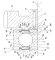
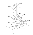
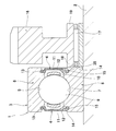
- FIG. 1 is a partial cross-sectional view showing a seal ring attached ball bearing according to a first example of an embodiment of the present invention in a state of being incorporated into a transmission for an automobile.
- FIG. 2A is an enlarged cross-sectional view showing the shape of the seal lip in the X portion of FIG. 1
- FIG. 2B is an enlarged cross-sectional view showing the shape of the seal lip in the same portion of the reference structure. is there.
- FIG. 3 is an enlarged cross-sectional view of a portion X in FIG.
- FIG. 4 is a partial cross-sectional view of the seal ring attached ball bearing for explaining the change in the positional relationship between the retainer and the seal lip due to the deflection of the retainer.
- FIG. 1 is a partial cross-sectional view showing a seal ring attached ball bearing according to a first example of an embodiment of the present invention in a state of being incorporated into a transmission for an automobile.
- FIG. 2A is an enlarged cross-sectional
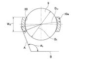
- FIG. 5 is a partial cross-sectional view of a cage holding a ball in a pocket to explain the limitation of the angle with respect to the inner continuous surface constituting the sealing lip in the present invention.
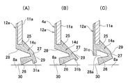
- FIGS. 6A to 6C are cross-sectional views similar to FIG. 2, showing second to fourth examples of the embodiment of the present invention.
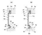
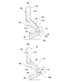
- FIGS. 7A and 7B are partial cross-sectional views of a seal ring attached ball bearing showing fifth and sixth examples of the embodiment of the present invention.
- 8 (A) and 8 (B) are partial cross-sectional views of a seal ring attached ball bearing showing seventh and eighth examples of the embodiment of the present invention.
- FIG. 9 is a cross-sectional view similar to FIG. 2 showing a ninth example of the embodiment of the present invention.
- FIG. 10 is a cross-sectional view similar to FIG. 2 showing the relationship between the interference and the thickness dimension of the constant thickness portion for the ninth example.
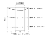
- FIG. 11 is a diagram showing the results of experiments conducted to confirm the influence of the relationship between the thickness dimension and the length dimension of the constant thickness portion on the tension force of the seal lip in the ninth example.
- FIGS. 12A and 12B are cross-sectional views similar to FIG. 2 showing another two examples to which the present invention is applied.
- FIG. 13 is a partial cross-sectional view showing a seal ring attached ball bearing according to a first example of the conventional structure incorporated in an automotive transmission.
- FIG. 14 is a view similar to FIG. 13 showing a second example of the conventional structure.
- the seal ring attached ball bearing 1a of this example includes a ball bearing 3a and a pair of seal rings 4a.
- the ball bearing 3a includes an outer ring 6a, an inner ring 8a, a plurality of balls 9, and a cage 10a.
- the outer ring 6a has a deep grooved outer ring raceway 5 at an axially intermediate portion of the inner circumferential surface, and is fitted and fixed to a casing (not shown) so that it does not rotate even when used.
- the inner ring 8a has a deep grooved inner ring raceway 7 at an axially intermediate portion of the outer peripheral surface, is externally fitted and fixed to the rotary shaft 2, and rotates with the rotary shaft 2 during use.
- the plurality of balls 9 are disposed rotatably between the outer ring raceway 5 and the inner ring raceway 7.
- the cage 10a is provided to hold the ball 9 in a rollable manner, but in the present example, the cage 10a is obtained by bending and forming an annular metal plate by press forming, and the circumference is circumferential
- a corrugated cage (press cage) is used, which is constructed by riveting together a pair of cage elements having a corrugated shape with respect to direction.
- the inner surface of the pocket 20 for holding the ball 9 is a partial spherical concave surface
- the outer surface of the portion corresponding to the pocket 20 is a partial spherical convex surface.
- the cross-sectional shape of the outer surface of the cage 10a with respect to a virtual plane including the center axis of the seal ring ball bearing 1a and the center of the ball 9 is a partial circle in which the middle portion axially protrudes more than both end portions in the radial direction. It has an arc shape.
- the seal ring 4a includes a cored bar 11a and an elastic member 12a.
- the cored bar 11 a is formed by forming a metal plate such as a steel plate into an annular shape, and from the outer peripheral edge of the flat annular portion 21 extending in the radial direction and the outer peripheral edge of the annular portion 21, a seal ring ball bearing It has a cylindrical portion 22 bent and extended toward the axial center side of 1a, and a bent portion 23 bent and extended radially outward from the tip end edge of the cylindrical portion 22.
- the elastic member 12a is made of a rubber material such as hydrogenated nitrile rubber, acrylic rubber, acrylonitrile butadiene rubber (nitrile rubber), or other elastomer, and is reinforced by the core 11a so as to enclose the core 11a. It is provided.
- the inner and outer peripheral edge portions of the elastic member 12 a protrude radially from the inner and outer peripheral edge portions of the core metal 11 a.
- a protruding portion on the inner peripheral edge side of the elastic member 12a is thin and constitutes a seal lip 14a having a substantially V-shaped cross-sectional shape that is open toward the axial direction outward of the seal ring ball bearing 1a. There is.
- the protruding portion on the outer peripheral edge side of the elastic member 12 a constitutes an annular locking portion 24.
- the seal ring 4a is engaged with the inner peripheral surface of the outer ring 6a and the outer peripheral surface of the inner ring 8a in a state where the annular locking portion 24 is locked in the locking grooves 13a formed on the inner peripheral surfaces of both axial ends of the outer ring 6a. Block the axially opposite openings of the annular internal space in which the balls 9 are disposed.
- the seal structure shaft seal structure in which the tip end edge of the seal lip 14a is in sliding contact with the outer peripheral surface of the inner ring 8a in the axial direction
- the radial dimension of the seal lip 14a is It is preferable to use a hydrogenated nitrile rubber having high tensile strength as the elastic material constituting the seal lip 14a because it becomes smaller and creep tends to occur.
- the seal lip 14 a having a substantially V-shaped cross-sectional shape is configured by connecting the outer diameter side inclined portion 25 and the inner diameter side inclined portion 26 by the continuous portion 27.
- the outer diameter side inclined portion 25 is inclined radially inward and toward the axial center side of the seal ring ball bearing 1a as being away from the inner peripheral edge of the metal core 11a (toward the tip edge).
- the inner diameter side inclined portion 26 is inclined radially inward and outward in the axial direction of the seal ring attached ball bearing 1 a as it gets away from the outer diameter side inclined portion 25 (toward the tip end edge).
- the continuous portion 27 continues the small diameter end of the outer diameter side inclined portion 25 and the large diameter end of the inner diameter side inclined portion 26.
- the portion surrounded in three directions by the inner peripheral surface of the outer diameter side inclined portion 25, the outer peripheral surface of the inner diameter side inclined portion 26, and the axial side surface (axial outer surface) of the continuous portion 27 has a wedge shape in cross section
- the groove part 28 which opposes the outer space side of the ring ball bearing 1a is comprised.
- the surface opposite to the groove portion 28 in the axial direction is an inner continuous surface 29 facing the inner space side of the seal ring ball bearing 1a.
- the cross-sectional shape of the inner continuous surface 29 is substantially linear in the free state of the seal lip 14a except for a slight distortion due to a manufacturing error or the like.
- the inner peripheral edge portion of the inner diameter side inclined portion 26, which is the tip end edge of the seal lip 14a, is in sliding contact with the outer peripheral surfaces of both end portions in the axial direction of the inner ring 8a.
- the axially outer end surfaces of the inner ring 8a are cylindrical surfaces 30 each having a straight generatrix shape, and seal grooves 15 (see FIG. 13) are provided on the axially outer end surface of the inner ring 8a.
- a flat surface-like load bearing surface an annular shape existing on a virtual plane orthogonal to the central axis of seal ring ball bearing 1a
- the transmission gear 16 has a tooth portion (for example, a helical gear) on the outer peripheral surface at a portion axially adjacent to the seal ring attached ball bearing 1a around an axially intermediate portion of the rotary shaft 2.
- a tooth portion for example, a helical gear
- the cylindrical boss 19 provided on the inner diameter side of the transmission gear 16 has the spacer 18 (see FIG. 13) on the load bearing surface 35a of the inner ring 8a. It is in direct contact without intervention.
- the gear reaction force acting on the transmission gear 16 is supported using the seal ring attached ball bearing 1a, and positioning of the transmission gear 16 in the axial direction is achieved.
- the angle ⁇ 1a with respect to the inner continuous surface 29a that constitutes the seal lip 14b is about 90 degrees ( ⁇ 1a 90 90 degrees)
- the inner continuous surface 29 is inclined in the direction toward the axial center side of the seal ring attached ball bearing 1a as it goes radially inward.
- the base end portion of the inner diameter side inclined section 26 (right end in FIG. 2) is, from the base end portion of the inner diameter side inclined portion 26a of the reference structure Also, it is disposed on the axial center side of the seal ring attached ball bearing 1a.
- the outer surface of the portion corresponding to the pocket 20 is a convex surface having a partial spherical shape.
- the continuous portion 27 and the inner diameter side are set such that the angle ⁇ 1 with respect to the inner continuous surface 29 is an angle ⁇ 0 or more ( ⁇ 1 ⁇ 0 ) with respect to the tangent A of the inner peripheral edge of the outer surface of the portion corresponding to the pocket 20 of the cage 10a.
- the deflection of the cage 10a as shown in FIG. 4 is based on the pocket gap existing between the inner surface of the pocket 20 and the rolling surface of the ball 9.
- the inner continuous surface 29 of the continuous portion 27 is made to enter the portion on the inner diameter side of the convex surface of the cage 10a while effectively avoiding the interference with the cage 10a. You can leave it
- the entire length (axial length) L 26 of the inner diameter side inclined portion 26 is lengthened by the amount that the inner continuous surface 29 portion is made to enter the portion existing on the inner diameter side of the convex surface of the cage 10a.
- the rigidity of the portion 26 can be reduced, and the frictional resistance of the sliding portion between the inner peripheral edge portion of the inner diameter side inclined portion 26 and the outer peripheral surface of the axial direction end portion of the inner ring 8a can be reduced.
- the upper limit value of the angle alpha 1 is regulated in terms of preventing the axial dimension of the seal lip 14a is excessively long.
- the angle ⁇ 1 is preferably about 150 degrees.
- the opening of the groove 28 is slightly inclined radially outward. That is, the groove 28 has a cross-sectional wedge shape in which the width dimension in the radial direction becomes wider toward the axial outer side (opening), but the bisector C of the inner and outer side surfaces in the radial direction of the groove 28 It is made to incline in the direction which goes to radial direction outward, as it goes to the axial direction outer side (left side of FIG. 2) of the ball bearing 1a. Specifically, with respect to the cross-sectional shape of a virtual plane including the central axis of seal ring 4a, bisector C and straight line B parallel to the central axis are opposite to the opening of groove 28 in the axial direction. I try to cross.
- the crossing angle ⁇ between the bisector C and the straight line B is greater than 0 ° and less than or equal to 30 ° (0 ⁇ ⁇ 30 °), preferably 5 ° or more, including the upper limit value It is regulated in relation to the inclination angle ⁇ of the inner peripheral surface of the inner diameter side inclined portion 26 described next.
- the intersection angle ⁇ is restricted to a range of 5 degrees to 10 degrees in order to restrict the inclination angle ⁇ of the inner peripheral surface of the inner diameter side inclined portion 26 to an appropriate range.
- the crossing angle ⁇ a between the bisector C of the groove 28a and the straight line B parallel to the central axis is approximately 0 degrees ( ⁇ a ⁇ 0 degrees). Become. For this reason, the total length L 26a of the inner diameter side inclined portion 26a can not be increased to the same extent as this example. In the case of the present example, by setting the angle ⁇ 1 with respect to the inner continuous surface 29 to be 104 degrees or more and restricting the crossing angle ⁇ to the above-mentioned range, the total length L 26 of the inner diameter side inclined portion 26 is 20% compared to the reference structure It can be made longer (L 26 1.21.2 L 26 a ).
- this value is a seal ring attached ball bearing of a general transmission for an automobile, and the gap between the cage 10a and the seal ring 4a is as much as possible (the interference between the cage 10a and the seal ring 4a is It is a value in the case of making it small in the range which can be prevented reliably.
- the angle ⁇ 1 with respect to the inner continuous surface 29 is smaller than the inclination angle ⁇ 2 with respect to the outer peripheral surface of the outer diameter side inclined portion 25 ( ⁇ 1 ⁇ 2 ).
- angle (alpha) 1 regarding the inner continuous surface 29 is an axial inside inside to the last It is regulated as the angle of the inner continuous surface 29 which is the surface of
- the inclination angle ⁇ of the inner peripheral surface of the inner diameter side inclined portion 26, that is, a straight line B parallel to the inner peripheral surface of the inner diameter side inclined portion 26 and the central axis with respect to the sectional shape of the imaginary plane including the central axis
- the crossing angle ⁇ is 15 degrees to 25 degrees.
- the inclination angle ⁇ of the inner peripheral surface of the inner diameter side inclined portion 26 exceeds 25 degrees, the rigidity (radial rigidity) in the radial direction of the inner diameter side inclined portion 26 becomes high.
- the distance between the inner peripheral edge of the core metal 11a and the outer peripheral surface of the inner ring 8a changes, the followability to the change is deteriorated, and the distortion generated in the inner diameter side inclined portion 26 becomes large.
- the inclination angle ⁇ is less than 15 degrees, the radial rigidity of the inner diameter side inclined portion 26 becomes too low, and the inner ring 8a is brought close to the inner peripheral edge of the core 11a and the outer peripheral surface of the inner ring 8a.
- a so-called solid contact occurs in which the outer peripheral surface and the inner peripheral surface of the inner diameter side inclined portion 26 abut each other in an excessively large area, and the frictional resistance acting on the sliding contact between the peripheral surfaces increases.
- the inclination angle ⁇ of the inner peripheral surface of the inner diameter side inclined portion 25 is restricted to the range of 15 degrees to 25 degrees, the interference of the seal lip 14a is a general value, that of the seal lip 14a.
- 0% of interference means a state in which the outer diameter of the inner ring 8a and the inner diameter in the free state of the seal lip 14a are exactly the same.
- the inner peripheral surface of the inner diameter side inclined portion 26 and the straight line B parallel to the central axis The tolerance angle ⁇ may be set to 15 degrees to 45 degrees, and the rigidity of the inner diameter side inclined portion 26 in the radial direction may be secured to some extent.
- the outer diameter of the load bearing surface 35a can be increased, and a large contact area between the load bearing surface 35a and one axial end face of the transmission gear 16 can be secured. While being able to do, reduction of dynamic torque can be aimed at. That is, in this example, a seal structure (shaft seal structure) in which the inner peripheral edge portion of the inner diameter side inclined portion 26 which is the tip edge of the seal lip 14a is in sliding contact with the cylindrical surface 30 which is the outer peripheral surface of the axial direction end portion of the inner ring 8a. Is adopted.
- the spacer 18 without providing the spacer 18 (see FIG. 13) between the seal ring ball bearing 1a of the present embodiment and the transmission gear 16, the axial direction one end face of the boss 19 constituting the transmission gear 16 is provided. And the load bearing surface 35a of the inner ring 8a can be contacted directly while securing a large contact area.
- the spacer 18 required in the conventional structure can be omitted without increasing the size of the seal ring ball bearing 1a, thereby reducing the number of parts and the number of assembling steps of the transmission for an automobile. It is possible to reduce the size and weight of the device.
- the cross-sectional shape of the seal lip 14a with a substantially transverse V-shaped along a movement path of the retainer 10a based on whirling (region), the inclination angle alpha 1 of the inner continuous surface 29 104 degrees And regulate. For this reason, the continuous portion 27 of the seal lip 14a can be inserted radially inward of the holder 10a while effectively avoiding interference with the holder 10a.
- the entire length of the inner diameter side inclined portion 26 constituting the seal lip 14a is secured long, and the surface pressure of the sliding contact portion between the tip edge of the seal lip 14a and the axial outer peripheral surface (cylindrical surface 30) of the inner ring 8a By keeping it low, dynamic torque of the seal ring ball bearing 1a can be reduced.
- the total length L 26 of the inner diameter side inclined portion 26 can be increased by about 20% as compared with the reference structure, the dynamic torque can be reduced by about 30%.
- Other configurations and effects are similar to those of the conventional structure.
- FIGS. 6A to 6C show second to fourth examples of the embodiment of the present invention.
- the secondary seal lips 31a to 31c are provided on the entire circumference of a part of the seal lips 14c to 14e within a range where the entire length of the seal lips 14c to 14e can be secured.
- the shapes, dimensions, and installation positions of these sub seal lips 31a to 31c are appropriately regulated in terms of improving the sealing performance of the seal lips 14c to 14e.
- the sub seal lips 31a and 31b shown in FIGS. 6A and 6B are shaped such that the continuous portion 27 extends radially inward, and the tip edge thereof is the shaft of the inner ring 8a.
- a labyrinth seal is configured on this portion so as to face the direction end portion outer peripheral surface (cylindrical surface 30) in proximity.
- the sub seal lip 31c shown in FIG. 6C protrudes radially inward from a portion located inside the inner peripheral edge portion of the core 11a, and closes a part of the opening of the groove 28a. There is.
- the configuration and operation of the other parts are the same as in the first example of the embodiment.
- FIGS. 7A and 7B show fifth and sixth examples of the embodiment of the present invention.
- the shape of the portion that makes the tip end edge of the seal lip 14 a in sliding contact with the outer peripheral surface in the axial direction of the inner ring 8 a is made different from the first example of the embodiment.
- a partially conical convex inclined surface 32 is formed on the outer peripheral surface of the inner ring 8a in the axial direction, and the tip edge of the seal lip 14a (inner diameter side inclination on the inclined surface 32)
- the inner peripheral edge portion of the portion 26 is in sliding contact over the entire circumference.
- the angle ⁇ and the angle ⁇ described in FIG. 2A are the angles between the generatrix of the inclined surface 32 and the bisector of the inner circumferential surface of the inner diameter side inclined portion 26 or the groove 28. is there.
- the small diameter stepped portion 33 is formed on the outer peripheral surface of the inner ring 8a in the axial direction, and the cylindrical surface 30a which is the outer peripheral surface of the small diameter stepped portion 33 The edge is in sliding contact over the entire circumference.
- the outer diameter of the load bearing surface of the inner ring 8a is smaller than in the first example of the embodiment, but can be made sufficiently larger than in the case of the conventional structure.
- the configuration and operation of the other parts are the same as in the first example of the embodiment.
- FIG. 8 shows seventh and eighth examples of the embodiment of the present invention.
- the locking structure of the seal ring 4a with respect to the inner peripheral surface of the axial direction end of the outer ring 6a is devised.
- the inner peripheral surface of the axial direction end portion of the outer ring 6a is a mere cylindrical surface, and the locking groove is not provided.
- the outer peripheral edge portion of the annular portion 21 constituting the core metal 11a on the inner peripheral surface of the axial end portion of the outer ring 6a as described above is substantially perpendicular to the axial center side (right side in FIG. 8) of the seal ring ball bearing 1a.
- the fitting cylindrical portion 34 which is bent to the inside, is fixedly fitted inward via the elastic member 12a. Even in the structure shown in FIG. 8B, the inner peripheral surface of the axial direction end portion of the outer ring 6a is a mere cylindrical surface, and the locking groove is not provided. And from the outer peripheral edge portion of the annular ring portion 21a constituting the core metal 11a on the inner peripheral surface of the axial end portion of such outer ring 6a, on the axial center side (right side in FIG. 8) of the seal ring ball bearing 1a. A fitting cylindrical portion 34a bent substantially at a right angle is directly fitted and fixed. In these structures, it is not necessary to form a locking groove on the inner peripheral surface of the axial direction end portion of the outer ring 6a, so that the processing cost can be reduced.
- the configuration and operation of the other parts are the same as in the first example of the embodiment.
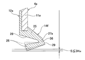
- the ninth example of the embodiment] 9 to 12 show a ninth example of the embodiment of the present invention.
- the relationship between the thickness dimension and the length dimension of the continuous portion 27a constituting the seal lip 14f is restricted. ing. That is, in the present example, the length dimension L 36 of the constant thickness portion 36 having a constant thickness dimension in the continuous portion 27 a is in the range of 1 to 2 times the thickness dimension H 36 of the constant thickness portion 36 ( In the illustrated example, it is regulated to 1.6 times (1H 36 ⁇ L 36 ⁇ 2H 36 ).
- the size of the degree of interference normally applied to the seal lip of the seal ring attached ball bearing of the automobile transmission means the tolerance of the inner diameter of the seal lip 14f and the outer diameter of the cylindrical surface 30 of the inner ring 8a. It is the size of the interference required when the relative displacement between the inner ring and the outer ring in the radial direction due to the load and the radial gap is taken into consideration.
- the upper limit value of the interference S is, as shown in FIG. 10, three or less (S ⁇ 3H 36 ) in relation to the thickness dimension H 36 of the constant thickness portion 36. It is preferable to set to.
- the value of the interference S is larger than three times the thickness dimension H 36 of the constant thickness portion 36, it is difficult to absorb the radial displacement only by the deformation of the inner side inclined portion 26.
- problems such as solid contact of the inner peripheral surface of the inner diameter side inclined portion 26 with the cylindrical surface 30 of the inner ring 8a, increase of the tension force and interference with the cage 10a easily occur.
- the size of the thickness dimension H 36 of the constant thickness portion 36 falls within the range of 200 ⁇ m to 400 ⁇ m in consideration of the bearing size used for an automotive transmission that is usually incorporated in a passenger car. If it is smaller than 200 ⁇ m, the constant thickness portion 36 becomes too thin and it is easy to cause a defect such as a tear at the time of manufacturing the seal ring 4a. The thickness of the seal lip is excessive and the torque performance is lowered.
- the design of the seal lip 14f is such that the distance from the inner peripheral edge of the seal lip 14f to the end face in the axial direction of the inner ring 8a is short or the seal lip 14f and the retainer 10a (see FIG. 1) are close.
- the space (design area) is limited, the inner peripheral edge (sliding portion) of the seal lip 14f is axially separated from the cylindrical surface 30, or a part of the seal lip 14f is attached to the retainer 10a. There is a high possibility of interference.
- FIG. 11 shows the relationship between the length dimension L 36 of the constant thickness portion 36 and the thickness dimension H 36 (L 36 / H 36 ) for three types of seal rings in which the size of the interference (S) is different.
- the experimental result which investigated the influence which it gives to the tension force of a seal lip is shown.
- the size of the interference (S) is set to "small (S H H 36 x 0.2)" or “medium (S H H 36 x 1)"
- the length dimension L 36 of the constant thickness portion 36 and the size of the interference (S) By regulating the relationship with the thickness dimension H 36 so as to satisfy 1H 36 ⁇ L 36 ⁇ 2H 36 , it can be confirmed that the tension force of the seal lip 14 f can be suppressed low.
- the size of the interference S is large in relation to the thickness dimension H 36 of the constant thickness portion 36, with the automotive transmission as an assembly target (1H 36 ⁇ S 36 ⁇ 3H 36) since it is necessary to set, by regulating the 1 to 2 times the range of the thickness H 36 the length L 36 of Teiatsu portion 36, it is possible to suppress the tension force of the seal lip 14f smaller it can. Further, in this example, it is possible to prevent a part of the seal lip 14 f from interfering with the cage 10 a or preventing the inner peripheral edge portion, which is a sliding contact portion, from coming off the cylindrical surface 30 in the axial direction.
- the structure to be a target for restricting the relationship between the length dimension L 36 and the thickness dimension H 36 of the constant thickness portion 36 in order to reduce the tension force is the constant thickness portion 36.
- the present invention is not limited to the structure in which the entire continuous portion 27a (inner continuous surface 29) configured to include the straight line is formed.
- the continuous portion between the outer peripheral surface of the outer diameter side inclined portion 25 and the inner continuous surface 29 a and the inner diameter side inclined portion 26 are less likely to be linear corner portions.
- arc portions 37a and 37b having a radius of curvature of about 0.1 mm are formed at the continuous portion between the inner circumferential surface and the inner continuous surface 29a.
- the length dimension of the arc portion (the distance between both ends of the constant thickness portion 36) is fixed.
- the length dimension L 36 of the thick portion 36 the relationship with the thickness dimension H 36 is regulated.
- an angle formed by a tangent passing at least a part of a portion corresponding to the constant thickness portion 36 in the inner continuous surface 29b and the central axis of the seal ring 4a is 104 degrees or more. The angle condition of the present invention is satisfied.
- the continuous portion is constituted of a constant thickness portion of arc shape and a thickness variation portion of arc shape
- a portion of the inner continuous surface corresponding to the constant thickness portion It is assumed that the angle condition of the present invention is satisfied when the angle between the tangent line passing at least in part and the central axis of the seal ring is 104 degrees or more.
- the other configurations and effects are the same as those of the first example of the embodiment.
- the transmission for an automobile in which the seal ring attached ball bearing according to the present invention is incorporated is not limited to the illustrated structure, and the transmission for an automobile having various structures can be adopted.
- the transmission gear disposed axially adjacent to the seal ring ball bearing is not limited to the structure rotatably supported via the radial needle bearing with respect to the rotation shaft, and can not relatively rotate.
- a supported structure can also be employed.
- the member disposed axially adjacent to the seal ring attached ball bearing according to the present invention is not limited to the transmission gear.
- the cage incorporated in the seal ring attached ball bearing of the present invention is not limited to the metal corrugated cage described in each example of the embodiments, and a synthetic resin cage can also be used.
- a resin composition in which a fibrous reinforcing agent such as glass fiber, carbon fiber, or aramid fiber is mixed with polyamide, polyphenylene sulfide (PPS), polyimide, polyether ether ketone (PEEK) or the like May be formed into a predetermined shape (for example, a crown shape consisting of a plurality of pillars of an annular base).
- the seal ring attached ball bearing according to the present invention is widely used in automatic transmissions of various structures such as manual transmissions (MTs), dual clutch transmissions (DCTs), planetary gear transmissions, belt transmissions, toroidal transmissions, etc. It is applicable.
- MTs manual transmissions
- DCTs dual clutch transmissions
- planetary gear transmissions belt transmissions
- toroidal transmissions etc. It is applicable.
Landscapes
- Engineering & Computer Science (AREA)
- General Engineering & Computer Science (AREA)
- Mechanical Engineering (AREA)
- Rolling Contact Bearings (AREA)
- Sealing Of Bearings (AREA)
- Sealing With Elastic Sealing Lips (AREA)
Priority Applications (3)
| Application Number | Priority Date | Filing Date | Title |
|---|---|---|---|
| CN201490000880.6U CN205677987U (zh) | 2013-07-09 | 2014-07-07 | 带密封圈球轴承 |
| EP14822586.5A EP3020990B1 (en) | 2013-07-09 | 2014-07-07 | Seal ring-equipped ball bearing |
| US14/904,091 US9816560B2 (en) | 2013-07-09 | 2014-07-07 | Seal ring-equipped ball bearing |
Applications Claiming Priority (4)
| Application Number | Priority Date | Filing Date | Title |
|---|---|---|---|
| JP2013143444 | 2013-07-09 | ||
| JP2013-143444 | 2013-07-09 | ||
| JP2014129533A JP6331754B2 (ja) | 2013-07-09 | 2014-06-24 | シールリング付玉軸受 |
| JP2014-129533 | 2014-06-24 |
Publications (1)
| Publication Number | Publication Date |
|---|---|
| WO2015005289A1 true WO2015005289A1 (ja) | 2015-01-15 |
Family
ID=52279969
Family Applications (1)
| Application Number | Title | Priority Date | Filing Date |
|---|---|---|---|
| PCT/JP2014/068083 Ceased WO2015005289A1 (ja) | 2013-07-09 | 2014-07-07 | シールリング付玉軸受 |
Country Status (5)
| Country | Link |
|---|---|
| US (1) | US9816560B2 (https=) |
| EP (1) | EP3020990B1 (https=) |
| JP (1) | JP6331754B2 (https=) |
| CN (1) | CN205677987U (https=) |
| WO (1) | WO2015005289A1 (https=) |
Cited By (1)
| Publication number | Priority date | Publication date | Assignee | Title |
|---|---|---|---|---|
| CN112747037A (zh) * | 2019-10-31 | 2021-05-04 | 新疆金风科技股份有限公司 | 轴系结构、密封组件以及风力发电机组 |
Families Citing this family (9)
| Publication number | Priority date | Publication date | Assignee | Title |
|---|---|---|---|---|
| TWI603020B (zh) * | 2016-11-04 | 2017-10-21 | 財團法人工業技術研究院 | 流體機械潤滑系統總成 |
| JP6376316B1 (ja) * | 2017-02-23 | 2018-08-22 | 日本精工株式会社 | 転がり軸受 |
| WO2018157910A1 (de) | 2017-02-28 | 2018-09-07 | Harmonic Drive Ag | Spannungswellengetriebe mit innendichtung |
| JP2018162870A (ja) * | 2017-03-27 | 2018-10-18 | 株式会社ジェイテクト | 転がり軸受 |
| US10458477B2 (en) * | 2017-03-28 | 2019-10-29 | Minebea Mitsumi Inc. | Seal for rolling bearing and rolling bearing |
| US11313469B2 (en) * | 2018-02-27 | 2022-04-26 | Nok Corporation | Sealing structure |
| EP4083453B1 (en) * | 2019-12-27 | 2026-02-18 | NSK Ltd. | Rolling bearing for air turbine |
| WO2021132688A1 (ja) * | 2019-12-27 | 2021-07-01 | 日本精工株式会社 | エアタービン用転がり軸受 |
| CN113931934A (zh) * | 2021-11-25 | 2022-01-14 | 湖北新火炬科技有限公司 | 一种低力矩密封结构的轮毂轴承单元 |
Citations (9)
| Publication number | Priority date | Publication date | Assignee | Title |
|---|---|---|---|---|
| JPH0682437U (ja) * | 1985-05-06 | 1994-11-25 | ザ・トリントン・カンパニ− | 多列ころ軸受 |
| JPH08296658A (ja) * | 1995-04-27 | 1996-11-12 | Ntn Corp | 転がり軸受のシール構造 |
| JP2001140907A (ja) | 1999-11-16 | 2001-05-22 | Nsk Ltd | 密封板付転がり軸受 |
| JP2002115724A (ja) | 2000-10-10 | 2002-04-19 | Nsk Ltd | トランスミッション用密封板付転がり軸受 |
| JP2011080527A (ja) | 2009-10-07 | 2011-04-21 | Nsk Ltd | 転がり軸受用シールリング及びシールリング付転がり軸受 |
| JP2011080497A (ja) | 2009-10-05 | 2011-04-21 | Nsk Ltd | 転がり軸受用シールリング及びシールリング付転がり軸受 |
| JP2011117548A (ja) * | 2009-12-04 | 2011-06-16 | Nsk Ltd | シールリング付転がり軸受及び電動モータ及び自動車用スロットル装置 |
| DE102010008947A1 (de) * | 2010-02-23 | 2011-08-25 | Schaeffler Technologies GmbH & Co. KG, 91074 | Wälzlager, insbesondere Kegelrollenlager |
| JP2013036493A (ja) * | 2011-08-04 | 2013-02-21 | Ntn Corp | 転がり軸受 |
Family Cites Families (8)
| Publication number | Priority date | Publication date | Assignee | Title |
|---|---|---|---|---|
| US3994545A (en) * | 1975-12-23 | 1976-11-30 | Textron, Inc. | Bearing and seal construction |
| IT8553531V0 (it) * | 1985-06-21 | 1985-06-21 | Riv Officine Di Villar Perosa | Complesso di tenuta particolarmente per cuscinetti |
| JPH0293520U (https=) * | 1989-01-13 | 1990-07-25 | ||
| US5470158A (en) * | 1994-12-29 | 1995-11-28 | The Torrington Company | Seal for rolling bearings |
| EP1286075B1 (en) | 1999-03-09 | 2004-05-12 | Nsk Ltd | Clutch release bearing |
| JP2008281196A (ja) * | 2007-04-11 | 2008-11-20 | Ntn Corp | 二輪車減速機用軸受 |
| JP5583460B2 (ja) * | 2009-05-14 | 2014-09-03 | Ntn株式会社 | トランスミッション用軸受 |
| EP2725247B1 (en) * | 2011-06-27 | 2019-08-21 | NTN Corporation | Rolling bearing |
-
2014
- 2014-06-24 JP JP2014129533A patent/JP6331754B2/ja not_active Expired - Fee Related
- 2014-07-07 WO PCT/JP2014/068083 patent/WO2015005289A1/ja not_active Ceased
- 2014-07-07 EP EP14822586.5A patent/EP3020990B1/en not_active Not-in-force
- 2014-07-07 CN CN201490000880.6U patent/CN205677987U/zh not_active Expired - Fee Related
- 2014-07-07 US US14/904,091 patent/US9816560B2/en not_active Expired - Fee Related
Patent Citations (9)
| Publication number | Priority date | Publication date | Assignee | Title |
|---|---|---|---|---|
| JPH0682437U (ja) * | 1985-05-06 | 1994-11-25 | ザ・トリントン・カンパニ− | 多列ころ軸受 |
| JPH08296658A (ja) * | 1995-04-27 | 1996-11-12 | Ntn Corp | 転がり軸受のシール構造 |
| JP2001140907A (ja) | 1999-11-16 | 2001-05-22 | Nsk Ltd | 密封板付転がり軸受 |
| JP2002115724A (ja) | 2000-10-10 | 2002-04-19 | Nsk Ltd | トランスミッション用密封板付転がり軸受 |
| JP2011080497A (ja) | 2009-10-05 | 2011-04-21 | Nsk Ltd | 転がり軸受用シールリング及びシールリング付転がり軸受 |
| JP2011080527A (ja) | 2009-10-07 | 2011-04-21 | Nsk Ltd | 転がり軸受用シールリング及びシールリング付転がり軸受 |
| JP2011117548A (ja) * | 2009-12-04 | 2011-06-16 | Nsk Ltd | シールリング付転がり軸受及び電動モータ及び自動車用スロットル装置 |
| DE102010008947A1 (de) * | 2010-02-23 | 2011-08-25 | Schaeffler Technologies GmbH & Co. KG, 91074 | Wälzlager, insbesondere Kegelrollenlager |
| JP2013036493A (ja) * | 2011-08-04 | 2013-02-21 | Ntn Corp | 転がり軸受 |
Cited By (1)
| Publication number | Priority date | Publication date | Assignee | Title |
|---|---|---|---|---|
| CN112747037A (zh) * | 2019-10-31 | 2021-05-04 | 新疆金风科技股份有限公司 | 轴系结构、密封组件以及风力发电机组 |
Also Published As
| Publication number | Publication date |
|---|---|
| JP2015034632A (ja) | 2015-02-19 |
| CN205677987U (zh) | 2016-11-09 |
| JP6331754B2 (ja) | 2018-05-30 |
| EP3020990A1 (en) | 2016-05-18 |
| EP3020990B1 (en) | 2019-03-20 |
| US20160153497A1 (en) | 2016-06-02 |
| US9816560B2 (en) | 2017-11-14 |
| EP3020990A4 (en) | 2017-07-26 |
Similar Documents
| Publication | Publication Date | Title |
|---|---|---|
| WO2015005289A1 (ja) | シールリング付玉軸受 | |
| JP5920443B2 (ja) | シールリング付き転がり軸受 | |
| EP3543553B1 (en) | Rolling bearing cage and rolling bearing | |
| US20070201782A1 (en) | Seal device and rolling bearing unit with seal device | |
| JP6866564B2 (ja) | 玉軸受 | |
| JP6852260B2 (ja) | ころ軸受 | |
| JP2005291450A (ja) | シールリング及びシールリング付転がり軸受ユニット | |
| JP5417481B2 (ja) | 歯車伝動装置 | |
| JP5870701B2 (ja) | シールリング付玉軸受 | |
| JP5493667B2 (ja) | シールリング付転がり軸受 | |
| JP3922729B2 (ja) | ラジアルニードル軸受 | |
| JP7043871B2 (ja) | クラッチ用軸受 | |
| JP2018168986A (ja) | 玉軸受 | |
| JP4811168B2 (ja) | 転がり軸受装置 | |
| WO2021171800A1 (ja) | 外輪付き円筒ころ軸受 | |
| JP5909918B2 (ja) | ころ軸受用保持器 | |
| JP5182082B2 (ja) | ころ軸受 | |
| JP5315881B2 (ja) | 転がり軸受 | |
| US10533607B2 (en) | Cage for radial roller bearing | |
| KR20200118279A (ko) | 씰링성이 향상된 구름 베어링 | |
| JP2022053007A (ja) | カムフォロア | |
| CN110566583A (zh) | 推力滚针轴承 | |
| JP2019157884A (ja) | オイルシール及びシール付軸受 | |
| JP2006083966A (ja) | トリポード型等速自在継手 | |
| JP2024038786A (ja) | 自動調心ころ軸受 |
Legal Events
| Date | Code | Title | Description |
|---|---|---|---|
| 121 | Ep: the epo has been informed by wipo that ep was designated in this application |
Ref document number: 14822586 Country of ref document: EP Kind code of ref document: A1 |
|
| WWE | Wipo information: entry into national phase |
Ref document number: 14904091 Country of ref document: US |
|
| NENP | Non-entry into the national phase |
Ref country code: DE |
|
| WWE | Wipo information: entry into national phase |
Ref document number: 2014822586 Country of ref document: EP |