WO2014199956A1 - 検出装置、及び検出装置の製造方法 - Google Patents
検出装置、及び検出装置の製造方法 Download PDFInfo
- Publication number
- WO2014199956A1 WO2014199956A1 PCT/JP2014/065257 JP2014065257W WO2014199956A1 WO 2014199956 A1 WO2014199956 A1 WO 2014199956A1 JP 2014065257 W JP2014065257 W JP 2014065257W WO 2014199956 A1 WO2014199956 A1 WO 2014199956A1
- Authority
- WO
- WIPO (PCT)
- Prior art keywords
- sensor
- main body
- housing
- magnetic field
- sensor main
- Prior art date
Links
Images


Classifications
-
- G—PHYSICS
- G01—MEASURING; TESTING
- G01R—MEASURING ELECTRIC VARIABLES; MEASURING MAGNETIC VARIABLES
- G01R33/00—Arrangements or instruments for measuring magnetic variables
- G01R33/02—Measuring direction or magnitude of magnetic fields or magnetic flux
- G01R33/06—Measuring direction or magnitude of magnetic fields or magnetic flux using galvano-magnetic devices
- G01R33/07—Hall effect devices
- G01R33/072—Constructional adaptation of the sensor to specific applications
-
- G—PHYSICS
- G01—MEASURING; TESTING
- G01P—MEASURING LINEAR OR ANGULAR SPEED, ACCELERATION, DECELERATION, OR SHOCK; INDICATING PRESENCE, ABSENCE, OR DIRECTION, OF MOVEMENT
- G01P3/00—Measuring linear or angular speed; Measuring differences of linear or angular speeds
- G01P3/42—Devices characterised by the use of electric or magnetic means
- G01P3/44—Devices characterised by the use of electric or magnetic means for measuring angular speed
- G01P3/48—Devices characterised by the use of electric or magnetic means for measuring angular speed by measuring frequency of generated current or voltage
- G01P3/481—Devices characterised by the use of electric or magnetic means for measuring angular speed by measuring frequency of generated current or voltage of pulse signals
- G01P3/487—Devices characterised by the use of electric or magnetic means for measuring angular speed by measuring frequency of generated current or voltage of pulse signals delivered by rotating magnets
-
- G—PHYSICS
- G01—MEASURING; TESTING
- G01D—MEASURING NOT SPECIALLY ADAPTED FOR A SPECIFIC VARIABLE; ARRANGEMENTS FOR MEASURING TWO OR MORE VARIABLES NOT COVERED IN A SINGLE OTHER SUBCLASS; TARIFF METERING APPARATUS; MEASURING OR TESTING NOT OTHERWISE PROVIDED FOR
- G01D11/00—Component parts of measuring arrangements not specially adapted for a specific variable
- G01D11/24—Housings ; Casings for instruments
- G01D11/245—Housings for sensors
-
- G—PHYSICS
- G01—MEASURING; TESTING
- G01D—MEASURING NOT SPECIALLY ADAPTED FOR A SPECIFIC VARIABLE; ARRANGEMENTS FOR MEASURING TWO OR MORE VARIABLES NOT COVERED IN A SINGLE OTHER SUBCLASS; TARIFF METERING APPARATUS; MEASURING OR TESTING NOT OTHERWISE PROVIDED FOR
- G01D5/00—Mechanical means for transferring the output of a sensing member; Means for converting the output of a sensing member to another variable where the form or nature of the sensing member does not constrain the means for converting; Transducers not specially adapted for a specific variable
- G01D5/12—Mechanical means for transferring the output of a sensing member; Means for converting the output of a sensing member to another variable where the form or nature of the sensing member does not constrain the means for converting; Transducers not specially adapted for a specific variable using electric or magnetic means
- G01D5/14—Mechanical means for transferring the output of a sensing member; Means for converting the output of a sensing member to another variable where the form or nature of the sensing member does not constrain the means for converting; Transducers not specially adapted for a specific variable using electric or magnetic means influencing the magnitude of a current or voltage
- G01D5/142—Mechanical means for transferring the output of a sensing member; Means for converting the output of a sensing member to another variable where the form or nature of the sensing member does not constrain the means for converting; Transducers not specially adapted for a specific variable using electric or magnetic means influencing the magnitude of a current or voltage using Hall-effect devices
- G01D5/145—Mechanical means for transferring the output of a sensing member; Means for converting the output of a sensing member to another variable where the form or nature of the sensing member does not constrain the means for converting; Transducers not specially adapted for a specific variable using electric or magnetic means influencing the magnitude of a current or voltage using Hall-effect devices influenced by the relative movement between the Hall device and magnetic fields
-
- G—PHYSICS
- G01—MEASURING; TESTING
- G01D—MEASURING NOT SPECIALLY ADAPTED FOR A SPECIFIC VARIABLE; ARRANGEMENTS FOR MEASURING TWO OR MORE VARIABLES NOT COVERED IN A SINGLE OTHER SUBCLASS; TARIFF METERING APPARATUS; MEASURING OR TESTING NOT OTHERWISE PROVIDED FOR
- G01D5/00—Mechanical means for transferring the output of a sensing member; Means for converting the output of a sensing member to another variable where the form or nature of the sensing member does not constrain the means for converting; Transducers not specially adapted for a specific variable
- G01D5/12—Mechanical means for transferring the output of a sensing member; Means for converting the output of a sensing member to another variable where the form or nature of the sensing member does not constrain the means for converting; Transducers not specially adapted for a specific variable using electric or magnetic means
- G01D5/244—Mechanical means for transferring the output of a sensing member; Means for converting the output of a sensing member to another variable where the form or nature of the sensing member does not constrain the means for converting; Transducers not specially adapted for a specific variable using electric or magnetic means influencing characteristics of pulses or pulse trains; generating pulses or pulse trains
- G01D5/245—Mechanical means for transferring the output of a sensing member; Means for converting the output of a sensing member to another variable where the form or nature of the sensing member does not constrain the means for converting; Transducers not specially adapted for a specific variable using electric or magnetic means influencing characteristics of pulses or pulse trains; generating pulses or pulse trains using a variable number of pulses in a train
- G01D5/2451—Incremental encoders
-
- G—PHYSICS
- G01—MEASURING; TESTING
- G01L—MEASURING FORCE, STRESS, TORQUE, WORK, MECHANICAL POWER, MECHANICAL EFFICIENCY, OR FLUID PRESSURE
- G01L5/00—Apparatus for, or methods of, measuring force, work, mechanical power, or torque, specially adapted for specific purposes
- G01L5/22—Apparatus for, or methods of, measuring force, work, mechanical power, or torque, specially adapted for specific purposes for measuring the force applied to control members, e.g. control members of vehicles, triggers
- G01L5/221—Apparatus for, or methods of, measuring force, work, mechanical power, or torque, specially adapted for specific purposes for measuring the force applied to control members, e.g. control members of vehicles, triggers to steering wheels, e.g. for power assisted steering
-
- G—PHYSICS
- G01—MEASURING; TESTING
- G01P—MEASURING LINEAR OR ANGULAR SPEED, ACCELERATION, DECELERATION, OR SHOCK; INDICATING PRESENCE, ABSENCE, OR DIRECTION, OF MOVEMENT
- G01P3/00—Measuring linear or angular speed; Measuring differences of linear or angular speeds
- G01P3/42—Devices characterised by the use of electric or magnetic means
- G01P3/44—Devices characterised by the use of electric or magnetic means for measuring angular speed
- G01P3/443—Devices characterised by the use of electric or magnetic means for measuring angular speed mounted in bearings
-
- G—PHYSICS
- G01—MEASURING; TESTING
- G01R—MEASURING ELECTRIC VARIABLES; MEASURING MAGNETIC VARIABLES
- G01R33/00—Arrangements or instruments for measuring magnetic variables
- G01R33/0052—Manufacturing aspects; Manufacturing of single devices, i.e. of semiconductor magnetic sensor chips
-
- G—PHYSICS
- G01—MEASURING; TESTING
- G01R—MEASURING ELECTRIC VARIABLES; MEASURING MAGNETIC VARIABLES
- G01R33/00—Arrangements or instruments for measuring magnetic variables
- G01R33/02—Measuring direction or magnitude of magnetic fields or magnetic flux
- G01R33/06—Measuring direction or magnitude of magnetic fields or magnetic flux using galvano-magnetic devices
- G01R33/07—Hall effect devices
Definitions
- the present invention relates to a detection device having a sensor for detecting a state quantity such as a magnetic field and temperature, and a method for manufacturing the detection device.
- a torque detection device that molds a Hall IC as a sensor for detecting a magnetic field with resin and detects a torque applied to a vehicle handle by a change in the strength of the magnetic field detected by the Hall IC is known (for example, see Patent Document 1).
- the torque detection device described in Patent Document 1 includes an input shaft connected to a steering wheel, an output shaft connected to a steering wheel, a torsion bar connecting the input shaft and the output shaft, a multipolar magnet, a pair of multipolar yokes, Two Hall ICs are provided, and the multi-pole magnet and the pair of multi-pole yokes are relatively rotated by twisting of the torsion bar caused by torque applied to the handle.
- a pair of annular magnetism collecting rings is arranged on the outer peripheral side of the pair of multipolar yokes, and each magnetism collecting ring is provided with a magnetism collecting portion projecting radially at one place in the circumferential direction.
- Two Hall ICs are arranged between the magnetism collecting part of one magnetism collecting ring and the magnetism collecting part of the other magnetism collecting ring.
- the two Hall ICs are molded on a resin member together with a pair of magnetism collecting rings.
- this invention aims at providing the detection apparatus which can suppress that the detection accuracy of a sensor falls by the heat
- a sensor main body including a detection element, a sensor having a plurality of lead wires drawn from the sensor main body, and a housing member having a housing for housing the sensor main body, And a molded device made of a molded resin formed to include at least a part of the housing member without being in contact with the sensor main body.
- At least the sensor main body portion of the sensor main body portion including the detection element and the sensor having a plurality of lead wires drawn from the sensor main body portion is accommodated in the housing member.
- a method for manufacturing a detection device comprising: a first step of housing the sensor body; and a second step of molding the mold resin including at least a part of the housing member without bringing molten resin into contact with the sensor body.
- the detection device and the manufacturing method of the detection device according to the present invention it is possible to suppress a decrease in detection accuracy of the sensor due to heat when the sensor is molded with resin.
- FIG. 1 is a cross-sectional view showing a configuration example of a rotation detection device according to a first embodiment of the present invention and a vehicle wheel bearing device having the rotation detection device.
- FIG. 2 is a partially enlarged view of FIG.
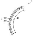
- FIG. 3 is a partially enlarged view showing the magnetic body.
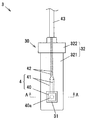
- FIG. 4 is a front view showing the sensor module according to the first embodiment of the present invention.
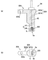
- 5A and 5B show a housing case constituting the sensor module of FIG. 4, wherein FIG. 5A is a cross-sectional view taken along the line AA of the housing case (not including the molded body), and FIG. 5B is a second view of the housing case.
- (C) is a top view of a storage case.
- FIGS. 6A and 6B show a sensor module according to a second embodiment of the present invention, in which FIG. 6A is a sectional view of the sensor module, and FIG. 6B is a bottom view of the sensor module.
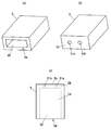
- FIGS. 7A and 7B show a housing case constituting the sensor module according to the second embodiment.
- FIGS. 7A and 7B are perspective views of the housing case, and
- FIG. 7C is a side view of the housing case.
- FIG. 1 is a cross-sectional view showing a configuration example of a rotation detection device 1 according to a first embodiment of the present invention and a vehicle wheel bearing device 10 having the rotation detection device 1.
- FIG. 2 is a partially enlarged view of FIG.
- FIG. 3 is a partially enlarged view showing the magnetic body 22.
- the wheel bearing device 10 includes a cylindrical main body 110 and an inner ring 11 having a flange portion 111 to which a wheel is attached, an outer ring 12 disposed on the outer peripheral side of the main body 110 of the inner ring 11, an inner ring 11 and an outer ring 12. And a rotation detecting device 1 for detecting the rotation speed of the inner ring 11 relative to the outer ring 12.
- a spline fitting portion 110 a for connecting the drive shaft along the rotation axis O is formed at the center portion of the main body portion 110 of the inner ring 11.
- the flange portion 111 of the inner ring 11 protrudes radially outward from the main body 110 and is formed integrally with the main body 110.
- the flange portion 111 is formed with a plurality of through holes 111a into which bolts for attaching a wheel (not shown) are press-fitted.
- the outer ring 12 is formed in a cylindrical shape, and is fixed to a knuckle 6 connected to the vehicle body via a suspension device by a plurality of bolts 61 (only one is shown in FIG. 1).
- the knuckle 6 is formed with a through hole 5a for attaching a sensor module 3 to be described later.
- the first seal member 14 is disposed on the flange portion 111 side of the inner ring 11, and the second seal member 15 is disposed on the opposite side (vehicle body side).
- the second seal member 15 includes a cored bar 151 having an L-shaped cross section and an elastic member 152 bonded to the cored bar 151 by vulcanization adhesion, and a cylindrical portion 151a formed on the outer periphery of the cored bar 151 has an outer ring. 12 is press-fitted into the outer peripheral surface.
- the elastic member 152 is bonded to a flange portion 151b extending inward from one end of the cylindrical portion 151a by, for example, vulcanization bonding.
- the core metal 151 is made of a nonmagnetic metal such as austenitic stainless steel or aluminum.
- the rotation detection device 1 includes a magnetic encoder 2 fixed to the outer periphery of the main body 110 in the inner ring 11, and a sensor module 3 for detecting a change in the magnetic field accompanying the rotation of the magnetic encoder 2.
- the magnetic encoder 2 includes an annular support portion 21 made of a nonmagnetic material fixed to the outer peripheral surface of the main body 110 in the inner ring 11, and an annular magnetic body 22 supported by the support portion 21.
- the magnetic body 22 is provided with a plurality of N poles 221 and a plurality of S poles 222 alternately along the circumferential direction, and rotates together with the wheels and the inner ring 11.
- the sensor module 3 includes a resin case 30, a magnetic field sensor 4, and a yoke 300 as a magnetic body disposed on the side opposite to the magnetic encoder 2 of the magnetic field sensor 4.
- the resin case 30 includes a housing case 31 made of a resin for housing the magnetic field sensor 4, and a molded body 32 made of a molded resin formed by including at least a part of the housing case 31.
- the sensor module 3 is fixed to the knuckle 6 with bolts 61.
- the rotation detection device 1 detects the intensity of the magnetic field that changes due to the rotation of the magnetic encoder 2 by the magnetic field sensor 4 of the sensor module 3 and outputs a signal corresponding to the intensity of the magnetic field.
- the inner ring 11 and the magnetic encoder 2 rotate around the rotation axis O along with the rotation, and the strength of the magnetic field of the magnetic encoder 2 detected by the magnetic field sensor 4 changes. It is possible to obtain the rotational speed of the wheel based on the period of change in the output signal.
- FIG. 4 is a front view showing the sensor module 3 according to the first embodiment of the present invention.
- the storage case 31 and the magnetic field sensor 4 inside the resin case 30 are indicated by solid lines and broken lines for the sake of explanation.
- the magnetic field sensor 4 includes a sensor main body 40 including a magnetic field detection element (Hall element) 40a that detects a magnetic flux density that changes due to the rotation of the magnetic encoder 2, and a plurality of (2 in this embodiment) drawn from the sensor main body 40.
- Main lead wire 41.
- the plurality of lead wires 41 are connected to the plurality of electric wires 42 included in the cable 43 drawn from the resin case 30 by soldering, welding, or the like.
- the sensor body 40 of the magnetic field sensor 4 is housed in the housing case 31.
- the housing case 31, the plurality of lead wires 41 led out from the housing case 31, and the plurality of electric wires 42 are collectively molded in the molded body 32.
- the molded body 32 is made of a molded resin that is molded by including the housing case 31 and the yoke 300 without contacting the sensor body 40 of the magnetic field sensor 4. More specifically, the molded body 32 integrally includes a main body portion 321 in which the housing case 31 and the yoke 300 are molded, and a fixing portion 322 that is fixed to the knuckle 6 by bolts 61.
- the plurality of electric wires 42 are bundled in the main body 321 and accommodated in the sheath of the cable 43.
- FIG. 4C is a front view showing the second resin member 312 to be performed, and FIG. 5A and 5B, the magnetic field sensor 4 is indicated by a two-dot chain line for explanation.
- the housing case 31 is made of hard resin such as ABS resin, for example, and is configured by combining the first resin member 311 and the second resin member 312.
- the first resin member 311 and the second resin member 312 can be formed by, for example, injection molding.
- the first resin member 311 includes a housing portion 311A that houses the sensor main body 40 of the magnetic field sensor 4 and a holding portion 311B that holds a plurality of lead wires 41.
- the second resin member 312 includes a housing portion 312A that houses the sensor main body 40 of the magnetic field sensor 4 and a holding portion 312B that holds the plurality of lead wires 41.
- a recess 311 a for accommodating the sensor main body 40 of the magnetic field sensor 4 is formed in the accommodating portion 311 ⁇ / b> A of the first resin member 311.
- a recess 312 a for accommodating the sensor main body 40 of the magnetic field sensor 4 is formed in the accommodating portion 312 ⁇ / b> A of the second resin member 312.
- the housing portion 31A of the housing case 31 is configured by combining the housing portion 311A of the first resin member 311 and the housing portion 312A of the second resin member 312. Further, the recess 311a of the first resin member 311 and the recess 312a of the second resin member 312 are combined to form a rectangular parallelepiped accommodation space 310.
- the housing case 31 is formed so that the housing portion 31 ⁇ / b> A surrounds the entire sensor main body 40, and the molded body 32 seals the housing portion 31 ⁇ / b> A of the housing case 31.
- the holding portion 311B of the first resin member 311 has a plurality (two in this embodiment) of holding grooves (first holding groove 311b and second holding groove 311c) for holding the plurality of lead wires 41. ) Is formed.
- the holding portion 312B of the second resin member 312 has a plurality of (two in this embodiment) holding grooves (first holding groove 312b and second holding hole) for holding the plurality of lead wires 41.
- a holding groove 312c) is formed.
- the holding portion 31 ⁇ / b> B of the housing case 31 is configured by combining the holding portion 311 ⁇ / b> B of the first resin member 311 and the holding portion 312 ⁇ / b> B of the second resin member 312.
- the first holding groove 311b of the first resin member 311 and the first holding groove 312b of the second resin member 312 are combined to form a cylindrical first holding hole 310b.
- the second holding groove 311c of one resin member 311 and the second holding groove 312c of the second resin member 312 are combined to form a cylindrical second holding hole 310c.
- the magnetic field sensor 4 includes a plurality of lead wires 41 supported by the first and second holding holes 310b and 310c of the holding portion 31B, whereby the sensor main body portion 40 is placed in the receiving space 310 of the receiving portion 31A. The position is fixed in a state where all the outer peripheral portions of 40 do not contact the accommodation space 310.
- the manufacturing method of the sensor module 3 includes a first step of housing at least the sensor body 40 in the housing portion 31A of the housing case 31 among the sensor body 40 and the plurality of lead wires 41, and a molten resin in the sensor body 40.
- the magnetic field sensor 4 is disposed in the first recess 312a of the second resin member 312 and the plurality of lead wires 41 are disposed in the first and second holding grooves 312b and 312c, respectively.
- the housing case 31 is formed by combining the second resin member 312 on which the magnetic field sensor 4 is disposed and the first resin member 311.
- the plurality of lead wires 41 are held in the first and second holding holes 310b and 310c, and the sensor main body 40 is in a state where all the outer peripheral portions of the sensor main body 40 are not in contact with the housing space 310. 1 in the accommodation space 310.
- the tip portions of the plurality of lead wires 41 are connected to the electric wires 42, respectively.
- the housing case 31 that houses the magnetic field sensor 4 connected to the electric wire 42 and the lead wire 41 is disposed in the molding space of the mold for forming the molded body 32, and the molten resin is placed in the molding space.
- the sensor body 40 is disposed in the first housing space 310 in a state where all the outer peripheral portions of the sensor body 40 do not contact the housing space 310, that is, the sensor body 40 is accommodated in the housing case 31. Since it is covered with the portion 31 ⁇ / b> A, the molten resin does not flow into the accommodation space 310 and does not contact the sensor body 40.
- the housing case 31 and the molded body 32 are integrated, and the resin case 30 is formed.
- the sensor main body 40 of the magnetic field sensor 4 is accommodated in the accommodation case 31 and does not contact the molten resin, it is possible to suppress the influence of the heat of the molten resin when the molded body 32 is formed. Thereby, it is possible to suppress the deterioration of the detection accuracy of the magnetic field detection element 40a and to ensure the reliability.
- the sensor main body 40 of the magnetic field sensor 4 is configured such that the plurality of lead wires 41 are held in the first and second holding holes 310b and 310c formed in the holding portion 31B of the holding case 31. It is supported in the 31 accommodation spaces 310. That is, since the sensor body 40 is supported without being in contact with the housing case 31, the heat of the molten resin at the time of molding the molded body 32 is directly transmitted from the housing case 31 to the sensor body 40. Can be prevented. Thereby, it can suppress more reliably that the detection accuracy of the magnetic field sensor 4 falls by the heat
- FIG. 6A and 6B show a sensor module according to the second embodiment of the present invention.
- FIG. 6A is a sectional view of the sensor module 3A
- FIG. 6B is a bottom view of the sensor module 3A.
- components having the same functions as those described in the first embodiment are denoted by the same or corresponding reference numerals, and redundant description thereof is omitted.
- the sensor module 3A includes a resin case 30A, the magnetic field sensor 4, and a yoke 300.
- the resin case 30 ⁇ / b> A includes a storage case 5 made of a resin that stores the magnetic field sensor 4, and a molded body 32 ⁇ / b> A made of a mold resin that is molded including the storage case 5.
- the molded body 32A integrally includes a main body portion 321A in which the housing case 5 and the yoke 300 are molded, and a fixing portion 322A in which a bolt insertion hole 322a through which a fixing bolt is inserted is formed.
- the sensor main body 40 of the magnetic field sensor 4 is housed inside the housing case 5, the sensor main body 40 of the magnetic field sensor 4 is housed.
- an opening 5a is formed on the bottom surface facing the outer peripheral surface of the inner ring 11 (shown in FIGS. 1 and 2) so that the sensor main body 40 accommodated in the housing case 5 faces the outside. .
- FIG. 7 shows a storage case 5 constituting the sensor module according to the second embodiment, where (a) is a perspective view of the storage case 5 and (b) is a storage case viewed from the side opposite to (a).
- FIG. 5 is a perspective view of FIG. 5, and FIG. In FIG.5 (c), the internal structure of the storage case 5 is shown with the broken line.
- the housing case 5 has a rectangular parallelepiped shape in which a housing space 50 for housing the sensor main body 40 of the magnetic field sensor 4 is formed, and an opening 5a is formed on one surface thereof.
- the housing case 5 integrally includes the housing portion 5A having the housing space 50 and the holding portion 5B in which the first and second holding holes 51a and 51b for holding the plurality of lead wires 41 are formed. is doing.
- the plurality of lead wires 41 are held by the holding portion 5B, whereby the sensor main body 40 is supported in the accommodation space 50 of the accommodation portion 5A.
- the plurality of lead wires 41 are inserted from the openings 5a, and the sensor main body 40 is accommodated in the accommodation space 50 while the plurality of lead wires 41 are inserted into the first and second holding holes 51a and 51b. Insert inside. And the front-end
- the housing case 5 housing the sensor main body 40 and the electric wire 42 are disposed in the molding space of the mold for forming the molded body 32A, and the opening 5a is pressed against the inner surface of the mold and closed. Then pour the molten resin. Thereby, the resin case 30 in which the housing case 5 and the molded body 32A are integrated is formed.
- the same operations and effects as those of the first embodiment can be obtained. Further, even if the sensor main body 40 generates heat when the sensor module 3A is used, the heat can be radiated from the opening 5a, and overheating of the magnetic field sensor 4 is suppressed. Thereby, the detection accuracy of the magnetic field sensor 4 can be maintained more reliably.
- the housing member (housing case 31) is formed so that the housing portion (31A) surrounds the entire sensor body (40), and the molded body (32) is formed by the housing member (housing).
- an opening (5a) is formed in the housing portion (5A) so that the sensor body (40) is exposed to the outside, and the molded body (32A) is The detection device (1) according to [1], which is molded without covering the opening (5a).
- the housing member (housing case 31, 5) has a holding portion (31B, 5B) for holding the lead wire (41), and the sensor (4) has the lead wire (41) [1] to [3] in which the sensor main body (40) is supported in the accommodation space (310, 50) of the accommodation part (31A, 5A) by being held by the holding part (31B, 5B).
- the detection apparatus (1) of any one of.
- (40) is accommodated in the accommodating part (31A, 5A) of the accommodating member (accommodating case 31, 5), and the accommodating member (accommodating case) without bringing molten resin into contact with the sensor main body (40).
- one magnetic field sensor 4 is disposed in the housing cases 31 and 5, but not limited to this, a plurality of magnetic field sensors 4 are housed in the housing cases 31 and 5. Also good.
- the detection element is not limited to this, and the detection element includes temperature, humidity, acceleration, pressure, and the like. You may detect a state quantity.
- the detection device of the present invention can suppress a decrease in detection accuracy of the sensor due to heat when the sensor is molded with resin.
Landscapes
- Physics & Mathematics (AREA)
- General Physics & Mathematics (AREA)
- Condensed Matter Physics & Semiconductors (AREA)
- Engineering & Computer Science (AREA)
- Manufacturing & Machinery (AREA)
- Transmission And Conversion Of Sensor Element Output (AREA)
- Measuring Magnetic Variables (AREA)
Abstract
センサを樹脂によってモールドする際の熱によりセンサの検出精度が低下することを抑制することができる検出装置、及び検出装置の製造方法を提供する。センサモジュール3は、磁界検出素子40aを含むセンサ本体部40、及びセンサ本体部40から引き出された複数のリード線41を有する磁界センサ4と、センサ本体部40を収容する収容部31Aを有する収容ケース31と、センサ本体部40に接することなく収容ケース31の少なくとも一部を含んで成形されたモールド樹脂からなるモールド成形体32とを備える。
Description
本発明は、磁界や温度等の状態量を検出するセンサを有する検出装置、及び検出装置の製造方法に関する。
従来、例えば磁界を検出するセンサとしてのホールICを樹脂によってモールドし、このホールICによって検出される磁界の強度の変化によって車両のハンドルに加えられるトルクを検出するトルク検出装置が知られている(例えば、特許文献1参照)。
特許文献1に記載のトルク検出装置は、ハンドルにつながる入力軸と、操舵輪につながる出力軸と、入力軸及び出力軸を連結するトーションバーと、多極磁石と、一対の多極ヨークと、2つのホールICとを備え、ハンドルに加えられるトルクによるトーションバーの捩じれによって多極磁石と一対の多極ヨークとが相対回転するように構成されている。一対の多極ヨークの外周側には環状をなす一対の集磁リングが配置され、それぞれの集磁リングには、周方向の1箇所に径方向に突出する集磁部が設けられている。一方の集磁リングの集磁部と他方の集磁リングの集磁部との間には2つのホールICが配置されている。
多極磁石と一対の多極ヨークとが相対回転すると、その相対回転角度に応じてホールICで検出される磁界の強度が変化するので、この磁界の強度の変化によってハンドルに加えられるトルクを検出することが可能である。2つのホールICは、一対の集磁リングと共に樹脂部材にモールドされている。
しかし、環状の樹脂部材をモールド成形する際には、2つのホールICを金型の成形空間内に配置し、この成形空間内に溶融した樹脂を射出する。射出された溶融樹脂は成形空間内でホールICと接触し、同樹脂は例えば270℃と高温であるため、ホールICの検出精度がモールド成形時の熱によって低下してしまうおそれがあった。
そこで、本発明は、センサを樹脂によってモールドする際の熱によりセンサの検出精度が低下することを抑制することができる検出装置、及び検出装置の製造方法を提供することを目的とする。
本発明は、その一実施形態に従い、検出素子を含むセンサ本体部、及び前記センサ本体部から引き出された複数のリード線を有するセンサと、前記センサ本体部を収容する収容部を有する収容部材と、前記センサ本体部に接することなく前記収容部材の少なくとも一部を含んで成形されたモールド樹脂からなるモールド成形体とを備えた検出装置を提供する。
また、本発明は、その一実施形態に従い、検出素子を含むセンサ本体部、及び前記センサ本体部から引き出された複数のリード線を有するセンサのうち、少なくとも前記センサ本体部を収容部材の収容部に収容する第1工程と、前記センサ本体部に溶融樹脂を接触させることなく前記収容部材の少なくとも一部を含んでモールド樹脂を成形する第2工程とを有する検出装置の製造方法を提供する。
本発明に係る検出装置、及び検出装置の製造方法によれば、センサを樹脂によってモールドする際の熱によりセンサの検出精度が低下することを抑制することができる。
[第1の実施の形態]
本発明の実施の形態について、図1~図5を参照して説明する。
本発明の実施の形態について、図1~図5を参照して説明する。
図1は、本発明の第1の実施の形態に係る回転検出装置1、及びこの回転検出装置1を有する車両用の車輪軸受装置10の構成例を示す断面図である。図2は、図1の部分拡大図である。図3は、磁性体22を示す部分拡大図である。
(車輪軸受装置10の構成)
車輪軸受装置10は、円筒状の本体部110、及び車輪が取り付けられるフランジ部111を有する内輪11と、内輪11の本体部110の外周側に配置された外輪12と、内輪11と外輪12との間に配置された複数の転動体13と、内輪11の外輪12に対する回転速度を検出するための回転検出装置1とを備えている。
車輪軸受装置10は、円筒状の本体部110、及び車輪が取り付けられるフランジ部111を有する内輪11と、内輪11の本体部110の外周側に配置された外輪12と、内輪11と外輪12との間に配置された複数の転動体13と、内輪11の外輪12に対する回転速度を検出するための回転検出装置1とを備えている。
内輪11の本体部110の中心部には、その回転軸線Oに沿ってドライブシャフトを連結するためのスプライン嵌合部110aが形成されている。内輪11のフランジ部111は、本体部110の径方向外側に突出して本体部110と一体に形成されている。フランジ部111には、図示しない車輪を取り付けるためのボルトが圧入される複数の貫通孔111aが形成されている。
外輪12は、円筒状に形成され、懸架装置を介して車体に連結されたナックル6に複数のボルト61(図1には1つのみ示す)によって固定されている。ナックル6には、後述するセンサモジュール3を取り付けるための貫通孔5aが形成されている。
内輪11と外輪12との間の環状の空間は、第1のシール部材14及び第2のシール部材15によって封止されている。第1のシール部材14は、内輪11のフランジ部111側に配置され、第2のシール部材15はその反対側(車体側)に配置されている。第2のシール部材15は、断面L字状の芯金151と、芯金151に加硫接着によって接着された弾性部材152とからなり、芯金151の外周に形成された円筒部151aが外輪12の外周面に圧入されている。弾性部材152は、円筒部151aの一端から内方に延びる鍔部151bに例えば加硫接着によって接着されている。芯金151は、オーステナイト系ステンレスやアルミニウム等の非磁性の金属からなる。
回転検出装置1は、内輪11における本体部110の外周に固定された磁気エンコーダ2と、磁気エンコーダ2の回転に伴う磁界の変化を検出するためのセンサモジュール3とを有して構成されている。磁気エンコーダ2は、内輪11における本体部110の外周面に固定された非磁性体からなる環状の支持部21と、支持部21に支持された環状の磁性体22とを有している。磁性体22は、図3に示すように、周方向に沿って複数のN極221及び複数のS極222が交互に設けられ、車輪及び内輪11と共に回転する。
センサモジュール3は、樹脂ケース30と、磁界センサ4と、磁界センサ4の磁気エンコーダ2とは反対側に配置された磁性体としてのヨーク300とを有している。樹脂ケース30は、磁界センサ4を収容する樹脂からなる収容ケース31と、収容ケース31の少なくとも一部を含んで成形されたモールド樹脂からなるモールド成形体32とを有している。センサモジュール3は、ボルト61によってナックル6に固定されている。
回転検出装置1は、磁気エンコーダ2の回転によって変化する磁界の強度をセンサモジュール3の磁界センサ4によって検出し、磁界の強度に応じた信号を出力する。車輪が回転すると、その回転に伴って内輪11及び磁気エンコーダ2が回転軸線Oを中心として回転し、磁界センサ4によって検出される磁気エンコーダ2の磁界の強度が変化するので、回転検出装置1から出力される信号の変化の周期に基づいて、車輪の回転速度を求めることが可能である。
(センサモジュール3の構成)
図4は、本発明の第1の実施の形態に係るセンサモジュール3を示す正面図である。図4では、説明のため、樹脂ケース30の内部における収容ケース31及び磁界センサ4を実線及び破線で示している。
図4は、本発明の第1の実施の形態に係るセンサモジュール3を示す正面図である。図4では、説明のため、樹脂ケース30の内部における収容ケース31及び磁界センサ4を実線及び破線で示している。
磁界センサ4は、磁気エンコーダ2の回転によって変化する磁束密度を検出する磁界検出素子(ホール素子)40aを含むセンサ本体部40と、センサ本体部40から引き出された複数(本実施の形態では2本)のリード線41とを有している。複数のリード線41はそれぞれ、樹脂ケース30から引き出されたケーブル43に含まれる複数の電線42に半田付けや溶接等によって接続されている。
磁界センサ4のセンサ本体部40は、収容ケース31に収容されている。収容ケース31、収容ケース31から導出された複数のリード線41、及び複数の電線42は、モールド成形体32に一括してモールドされている。
モールド成形体32は、磁界センサ4のセンサ本体部40に接することなく、収容ケース31及びヨーク300を含んでモールド成形されたモールド樹脂からなる。より具体的には、モールド成形体32は、収容ケース31及びヨーク300がモールドされた本体部321と、ナックル6にボルト61によって固定される固定部322とを一体に有している。複数の電線42は、本体部321内にて束ねられ、ケーブル43のシースの内部に収容されている。
(収容ケース31の構成)
図5は、図4のセンサモジュールを構成する収容ケース31を示し、(a)は(モールド成形体を含まない)収容ケース31のA-A線断面図、(b)は収容ケース31を構成する第2の樹脂部材312を示す正面図、(c)は収容ケース31の上面図である。なお、図5(a)及び(b)では、説明のために磁界センサ4を二点鎖線で示している。
図5は、図4のセンサモジュールを構成する収容ケース31を示し、(a)は(モールド成形体を含まない)収容ケース31のA-A線断面図、(b)は収容ケース31を構成する第2の樹脂部材312を示す正面図、(c)は収容ケース31の上面図である。なお、図5(a)及び(b)では、説明のために磁界センサ4を二点鎖線で示している。
収容ケース31は、例えばABS樹脂等の硬質の樹脂からなり、第1の樹脂部材311及び第2の樹脂部材312が組み合わされて構成されている。第1の樹脂部材311及び第2の樹脂部材312は、例えば射出成型によって形成することができる。
第1の樹脂部材311は、磁界センサ4のセンサ本体部40を収容する収容部311Aと、複数のリード線41を保持する保持部311Bとを有している。同様に、第2の樹脂部材312は、磁界センサ4のセンサ本体部40を収容する収容部312Aと、複数のリード線41を保持する保持部312Bとを有している。
第1の樹脂部材311の収容部311Aには、磁界センサ4のセンサ本体部40を収容するための凹部311aが形成されている。同様に、第2の樹脂部材312の収容部312Aには、磁界センサ4のセンサ本体部40を収容するための凹部312aが形成されている。
第1の樹脂部材311の収容部311Aと第2の樹脂部材312の収容部312Aとが組み合わされることにより、収容ケース31の収容部31Aが構成される。また、第1の樹脂部材311の凹部311aと第2の樹脂部材312の凹部312aとが組み合わされることにより、直方体状の収容空間310が形成される。
収容ケース31は、収容部31Aがセンサ本体部40の全体を囲むように形成され、モールド成形体32は、収容ケース31の収容部31Aを封止している。
第1の樹脂部材311の保持部311Bには、複数のリード線41を保持するための複数(本実施の形態では2つ)の保持溝(第1の保持溝311b及び第2の保持溝311c)が形成されている。同様に、第2の樹脂部材312の保持部312Bには、複数のリード線41を保持するための複数(本実施の形態では2つ)の保持溝(第1の保持溝312b及び第2の保持溝312c)が形成されている。
図5(c)に示すように、第1の樹脂部材311の保持部311Bと第2の樹脂部材312の保持部312Bとが組み合わされることにより、収容ケース31の保持部31Bが構成される。また、第1の樹脂部材311の第1の保持溝311bと第2の樹脂部材312の第1の保持溝312bとが組み合わされることにより、円筒状の第1の保持孔310bが形成され、第1の樹脂部材311の第2の保持溝311cと第2の樹脂部材312の第2の保持溝312cとが組み合わされることにより、円筒状の第2の保持孔310cが形成される。
磁界センサ4は、複数のリード線41が保持部31Bの第1及び第2の保持孔310b,310cに支持されることにより、センサ本体部40が収容部31Aの収容空間310内にセンサ本体部40の全ての外周部が収容空間310に接触しない状態で位置固定されている。
(センサモジュール3の製造方法)
次に、センサモジュール3の製造方法について説明する。
次に、センサモジュール3の製造方法について説明する。
センサモジュール3の製造方法は、センサ本体部40、及び複数のリード線41のうち、少なくともセンサ本体部40を収容ケース31の収容部31Aに収容する第1工程と、センサ本体部40に溶融樹脂を接触させることなく収容ケース31を含んでモールド樹脂を成形し、モールド成形体32を得る第2工程とを備える。
第1工程では、磁界センサ4を第2の樹脂部材312の第1の凹部312aに配置し、複数のリード線41を第1及び第2の保持溝312b,312cにそれぞれ配置する。次に、磁界センサ4を配置した第2の樹脂部材312と第1の樹脂部材311とを組み合わせて、収容ケース31を形成する。これにより、複数のリード線41が第1及び第2の保持孔310b,310cに保持されると共に、センサ本体部40がセンサ本体部40の全ての外周部が収容空間310に接触しない状態で第1の収容空間310内に配置される。
次に、複数のリード線41の先端部(センサ本体部40とは反対側)を電線42にそれぞれ接続する。
第2工程では、モールド成形体32を形成するための型の成形空間内に、電線42およびリード線41を接続した磁界センサ4を収容した収容ケース31を配置し、成形空間内に溶融樹脂を流し込む。このとき、センサ本体部40の全ての外周部が収容空間310に接触しない状態でセンサ本体部40が第1の収容空間310内に配置され、即ち、センサ本体部40は、収容ケース31の収容部31Aで覆われているため、溶融樹脂が収容空間310に流れ込むんでセンサ本体部40に接触することがない。これにより、収容ケース31とモールド成形体32とが一体化され、樹脂ケース30が形成される。
(第1の実施の形態の作用及び効果)
上記した第1の実施の形態によれば、以下に示す作用及び効果が得られる。
上記した第1の実施の形態によれば、以下に示す作用及び効果が得られる。
(1)磁界センサ4のセンサ本体部40は収容ケース31に収容され、溶融樹脂に接触しないので、モールド成形体32を成形する際における溶融樹脂の熱による影響を抑えることができる。これにより、磁界検出素子40aの検出精度の劣化を抑制し、信頼性を確保することが可能となる。
(2)磁界センサ4のセンサ本体部40は、複数のリード線41が収容ケース31の保持部31Bに形成された第1及び第2の保持孔310b,310cに保持されることにより、収容ケース31の収容空間310内に支持される。つまり、センサ本体部40は、収容ケース31に接することなく支持されるので、モールド成形体32のモールド成形時における溶融樹脂の熱が収容ケース31から直接的にセンサ本体部40に伝達することを防ぐことができる。これにより、モールド成形体32のモールド成形時の熱により磁界センサ4の検出精度が低下することをより確実に抑制することができる。
[第2の実施の形態]
次に、本発明の第2の実施の形態について、図6及び図7を参照して説明する。
次に、本発明の第2の実施の形態について、図6及び図7を参照して説明する。
図6は、本発明の第2の実施の形態に係るセンサモジュールを示し、(a)はセンサモジュール3Aの断面図、(b)はセンサモジュール3Aの底面図である。図6において、第1の実施の形態について説明したものと機能が共通する構成要素については、同一又は対応する符号を付してその重複した説明を省略する。
本実施の形態に係るセンサモジュール3Aは、樹脂ケース30Aと、磁界センサ4と、ヨーク300とを有している。樹脂ケース30Aは、磁界センサ4を収容する樹脂からなる収容ケース5と、収容ケース5を含んで成形されたモールド樹脂からなるモールド成形体32Aとを有している。モールド成形体32Aは、収容ケース5及びヨーク300がモールドされた本体部321Aと、固定用のボルトを挿通させるボルト挿通孔322aが形成された固定部322Aとを一体に有している。
収容ケース5の内部には、磁界センサ4のセンサ本体部40が収容されている。樹脂ケース30Aには、内輪11(図1,2に示す)の外周面に対向する底面に、収容ケース5の内部に収容されたセンサ本体部40を外部に臨ませる開口5aが形成されている。
図7は、第2の実施の形態に係るセンサモジュールを構成する収容ケース5を示し、(a)は収容ケース5の斜視図、(b)は(a)とは反対側から見た収容ケース5の斜視図、(c)は収容ケース5の側面図である。図5(c)には、収容ケース5の内部の構造を破線で示している。
収容ケース5は、磁界センサ4のセンサ本体部40を収容する収容空間50が内部に形成された直方体状であり、その一つの面に開口5aが形成されている。開口5aが形成された面とは反対側の底面5bには、磁界センサ40の複数(2本)のリード線41をそれぞれ挿通させて保持する第1の保持孔51a及び第2の保持孔51bが形成されている。
このように、収容ケース5は、収容空間50を有する収容部5Aと、複数のリード線41を保持する第1及び第2の保持孔51a,51bが形成された保持部5Bとを一体に有している。磁界センサ4は、複数のリード線41が保持部5Bに保持されることにより、センサ本体部40が収容部5Aの収容空間50内に支持される。
センサモジュール3Aを製造する際は、開口5aから複数のリード線41を挿入し、複数のリード線41を第1及び第2の保持孔51a,51bに挿通させながらセンサ本体部40を収容空間50内に挿入する。そして、第1及び第2の保持孔51a,51bを通過したリード線41の先端部を電線42にそれぞれ接続する。その後、モールド成形体32Aを形成するための金型の成形空間内に、センサ本体部40を収容した収容ケース5及び電線42を配置し、開口5aを金型の内面等に押し付けて塞いだ状態で溶融樹脂を流し込む。これにより、収容ケース5とモールド成形体32Aとが一体化された樹脂ケース30が形成される。
本実施の形態によっても、第1の実施の形態と同様の作用及び効果が得られる。また、センサモジュール3Aの使用時においてセンサ本体部40が発熱しても、その熱を開口5aから放熱することができ、磁界センサ4の過熱が抑制される。これにより、磁界センサ4の検出精度をより確実に維持することができる。
(実施の形態のまとめ)
次に、以上説明した実施の形態から把握される技術思想について、実施の形態における符号等を援用して記載する。ただし、以下の記載における各符号等は、特許請求の範囲における構成要素を実施の形態に具体的に示した部材等に限定するものではない。
次に、以上説明した実施の形態から把握される技術思想について、実施の形態における符号等を援用して記載する。ただし、以下の記載における各符号等は、特許請求の範囲における構成要素を実施の形態に具体的に示した部材等に限定するものではない。
[1]検出素子(40a)を含むセンサ本体部(40)、及び前記センサ本体部(40)から引き出された複数のリード線(41)を有するセンサ(4)と、前記センサ本体部(40)を収容する収容部(31A,5A)を有する収容部材(収容ケース31,5)と、前記センサ本体部(40)に接することなく前記収容部材(収容ケース31,5)の少なくとも一部を含んで成形されたモールド樹脂からなるモールド成形体(32,32A)とを備えた検出装置(1)。
[3]前記収容部材(収容ケース31)は、前記収容部(31A)が前記センサ本体部(40)の全体を囲むように形成され、前記モールド成形体(32)は、前記収容部材(収容ケース31)の前記収容部(31A)を封止している、[1]に記載の検出装置(1)。
[2]前記収容部材(収容ケース5)には、前記センサ本体部(40)を外部に臨ませる開口(5a)が前記収容部(5A)に形成され、前記モールド成形体(32A)は、前記開口(5a)を覆うことなくモールド成形されている、[1]に記載の検出装置(1)。
[4]前記収容部材(収容ケース31,5)は、前記リード線(41)を保持する保持部(31B,5B)を有し、前記センサ(4)は、前記リード線(41)が前記保持部(31B,5B)に保持されることにより、前記センサ本体部(40)が前記収容部(31A,5A)の収容空間(310,50)内に支持された、[1]乃至[3]の何れか1項に記載の検出装置(1)。
[5]検出素子(40a)を含むセンサ本体部(40)、及び前記センサ本体部(40)から引き出された複数のリード線(41)を有するセンサ(4)のうち、少なくとも前記センサ本体部(40)を収容部材(収容ケース31,5)の収容部(31A,5A)に収容する第1工程と、前記センサ本体部(40)に溶融樹脂を接触させることなく前記収容部材(収容ケース31,5)の少なくとも一部を含んでモールド樹脂を成形する第2工程とを有する検出装置(1)の製造方法。
以上、本発明の実施の形態を説明したが、上記に記載した実施の形態は特許請求の範囲に係る発明を限定するものではない。また、実施の形態の中で説明した特徴の組合せの全てが発明の課題を解決するための手段に必須であるとは限らない点に留意すべきである。
上記第1及び第2の実施の形態では、収容ケース31,5内に1つの磁界センサ4を配置したが、これに限らず、複数の磁界センサ4を収容ケース31,5内に収容してもよい。
また、モールド成形体32,32Aの本体部321,321A及び固定部322,322Aの形状に制限はなく、収容ケース31,5と、複数のリード線41が一括してモールドされていればよい。
また、上記第1及び第2の実施の形態では、検出素子として磁界を検出するホール素子を用いた場合について説明したが、これに限らず、検出素子は温度や湿度、あるいは加速度や圧力等の状態量を検出するものであってもよい。
本発明の検出装置は、センサを樹脂によってモールドする際の熱によりセンサの検出精度が低下することを抑制することができる。
1 回転検出装置
2 磁気エンコーダ
3,3A センサモジュール
4 磁界センサ
5 収容ケース
5A 収容部
5B 保持部
5a 貫通孔
5a 開口
5b 底面
6 ナックル
10 車輪軸受装置
11 内輪
12 外輪
13 転動体
14 第1のシール部材
15 第2のシール部材
21 支持部
22 磁性体
30,30A 収樹ケース
31 収容ケース
31A 収容部
31B 保持部
32,32A モールド成形体
40 センサ本体部
40 本体部
40 磁界センサ
40 センサ本体部
40a 磁界検出素子
41 リード線
42 電線
43 ケーブル
50 収容空間
51a,51b 第1及び第2の保持孔
61 ボルト
110 本体部
110a スプライン嵌合部
111 フランジ部
111a 貫通孔
151 芯金
151a 円筒部
151b 鍔部
152 弾性部材
221 N極
222 S極
300 ヨーク
310 収容空間
310b,310c 第1及び第2の保持孔
311 第1の樹脂部材
311A 収容部
311B 保持部
311a 凹部
311b,311c 第1及び第2の保持溝
312 第2の樹脂部材
312A 収容部
312B 保持部
312a 凹部
312b,312c 第1及び第2の保持溝
321,321A 本体部
322,322A 固定部
322a ボルト挿通孔
Claims (5)
- 検出素子を含むセンサ本体部、及び前記センサ本体部から引き出された複数のリード線を有するセンサと、
前記センサ本体部を収容する収容部を有する収容部材と、
前記センサ本体部に接することなく前記収容部材の少なくとも一部を含んで成形されたモールド樹脂からなるモールド成形体とを備えた検出装置。 - 前記収容部材は、前記収容部が前記センサ本体部の全体を囲むように形成され、前記モールド成形体は、前記収容部材の前記収容部を封止している、請求項1に記載の検出装置。
- 前記収容部材には、前記センサ本体部を外部に臨ませる開口が前記収容部に形成され、前記モールド成形体は、前記開口を覆うことなくモールド成形されている、請求項1に記載の検出装置。
- 前記収容部材は、前記リード線を保持する保持部を有し、
前記センサは、前記リード線が前記保持部に保持されることにより、前記センサ本体部が前記収容部の収容空間内に支持された、請求項1乃至3の何れか1項に記載の検出装置。 - 検出素子を含むセンサ本体部、及び前記センサ本体部から引き出された複数のリード線を有するセンサのうち、少なくとも前記センサ本体部を収容部材の収容部に収容する第1工程と、
前記センサ本体部に溶融樹脂を接触させることなく前記収容部材の少なくとも一部を含んでモールド樹脂を成形する第2工程とを有する検出装置の製造方法。
Priority Applications (3)
| Application Number | Priority Date | Filing Date | Title |
|---|---|---|---|
| CN201480032723.8A CN105358939B (zh) | 2013-06-10 | 2014-06-09 | 检测装置以及检测装置的制造方法 |
| US14/896,631 US10101412B2 (en) | 2013-06-10 | 2014-06-09 | Sensing device and method for manufacturing sensing device |
| EP14811221.2A EP3009802B1 (en) | 2013-06-10 | 2014-06-09 | Sensing device and method for manufacturing sensing device |
Applications Claiming Priority (2)
| Application Number | Priority Date | Filing Date | Title |
|---|---|---|---|
| JP2013121473A JP5949672B2 (ja) | 2013-06-10 | 2013-06-10 | 検出装置、及び検出装置の製造方法 |
| JP2013-121473 | 2013-06-10 |
Publications (1)
| Publication Number | Publication Date |
|---|---|
| WO2014199956A1 true WO2014199956A1 (ja) | 2014-12-18 |
Family
ID=52022249
Family Applications (1)
| Application Number | Title | Priority Date | Filing Date |
|---|---|---|---|
| PCT/JP2014/065257 WO2014199956A1 (ja) | 2013-06-10 | 2014-06-09 | 検出装置、及び検出装置の製造方法 |
Country Status (5)
| Country | Link |
|---|---|
| US (1) | US10101412B2 (ja) |
| EP (1) | EP3009802B1 (ja) |
| JP (1) | JP5949672B2 (ja) |
| CN (2) | CN108534804B (ja) |
| WO (1) | WO2014199956A1 (ja) |
Cited By (2)
| Publication number | Priority date | Publication date | Assignee | Title |
|---|---|---|---|---|
| EP3176554A1 (en) * | 2015-12-03 | 2017-06-07 | Jtekt Corporation | Sensor assembly and sensor assembly manufacturing method |
| CN107101757A (zh) * | 2015-12-03 | 2017-08-29 | 株式会社捷太格特 | 传感器组件以及传感器组件的制造方法 |
Families Citing this family (4)
| Publication number | Priority date | Publication date | Assignee | Title |
|---|---|---|---|---|
| DE102014208510A1 (de) * | 2014-05-07 | 2015-11-12 | Bayerische Motoren Werke Aktiengesellschaft | Sensorring |
| JP6455207B2 (ja) * | 2015-02-16 | 2019-01-23 | 日立金属株式会社 | 樹脂成形体付きケーブル及びその製造方法 |
| JP6838306B2 (ja) | 2016-07-08 | 2021-03-03 | 日立金属株式会社 | 車載用検出装置 |
| JP6748931B1 (ja) * | 2019-04-02 | 2020-09-02 | 日立金属株式会社 | 回転検出装置 |
Citations (5)
| Publication number | Priority date | Publication date | Assignee | Title |
|---|---|---|---|---|
| JP2005098761A (ja) * | 2003-09-22 | 2005-04-14 | Koyo Seiko Co Ltd | 回転検出器 |
| JP2005265581A (ja) | 2004-03-18 | 2005-09-29 | Favess Co Ltd | トルク検出装置 |
| JP2008128647A (ja) * | 2006-11-16 | 2008-06-05 | Aisan Ind Co Ltd | 回転角センサ及びスロットル装置 |
| JP2010197137A (ja) * | 2009-02-24 | 2010-09-09 | Denso Corp | 回転検出装置および回転検出装置の製造方法 |
| JP2013088335A (ja) * | 2011-10-20 | 2013-05-13 | Mitsubishi Electric Corp | センサ装置 |
Family Cites Families (18)
| Publication number | Priority date | Publication date | Assignee | Title |
|---|---|---|---|---|
| US4649447A (en) * | 1985-08-15 | 1987-03-10 | International Business Machines | Combed MR sensor |
| JPH0512763Y2 (ja) | 1987-02-26 | 1993-04-02 | ||
| JPH064260Y2 (ja) | 1987-05-22 | 1994-02-02 | 住友電気工業株式会社 | センサ構造 |
| JP2572139B2 (ja) * | 1990-01-25 | 1997-01-16 | 旭化成工業株式会社 | 磁気抵抗センサー |
| JPH0968403A (ja) * | 1995-08-31 | 1997-03-11 | Denso Corp | スロットルバルブ開度センサ |
| JP2001289610A (ja) * | 1999-11-01 | 2001-10-19 | Denso Corp | 回転角度検出装置 |
| JP2004198240A (ja) * | 2002-12-18 | 2004-07-15 | Denso Corp | センサ装置 |
| JP2005106796A (ja) | 2003-08-05 | 2005-04-21 | Fuji Koki Corp | 圧力センサ |
| JP2005227156A (ja) * | 2004-02-13 | 2005-08-25 | Honda Lock Mfg Co Ltd | センサ装置 |
| JP2006308330A (ja) * | 2005-04-26 | 2006-11-09 | Denso Corp | センサ装置およびその製造方法 |
| JP3799362B1 (ja) * | 2005-08-25 | 2006-07-19 | 山洋電気株式会社 | 磁気センサ付き回転電機 |
| JP4716103B2 (ja) * | 2005-10-27 | 2011-07-06 | アイシン精機株式会社 | 回転センサの製造方法 |
| US7946555B2 (en) * | 2006-11-16 | 2011-05-24 | Aisan Kogyo Kabushiki Kaisha | Rotational angle sensors and throttle devices |
| DE102008054743A1 (de) | 2008-12-16 | 2010-06-17 | Robert Bosch Gmbh | Vorrichtung und Verfahren zur Herstellung einer Vorrichtung |
| JP5437147B2 (ja) * | 2010-04-22 | 2014-03-12 | 愛三工業株式会社 | 回転角度検出装置 |
| JP5014468B2 (ja) * | 2010-06-16 | 2012-08-29 | 三菱電機株式会社 | 回転センサ |
| US9116021B2 (en) | 2011-05-18 | 2015-08-25 | Mitsubishi Electric Corporation | Sensor device |
| JP5523389B2 (ja) * | 2011-05-18 | 2014-06-18 | 三菱電機株式会社 | 磁気検出装置 |
-
2013
- 2013-06-10 JP JP2013121473A patent/JP5949672B2/ja active Active
-
2014
- 2014-06-09 WO PCT/JP2014/065257 patent/WO2014199956A1/ja active Application Filing
- 2014-06-09 CN CN201810270229.5A patent/CN108534804B/zh active Active
- 2014-06-09 EP EP14811221.2A patent/EP3009802B1/en active Active
- 2014-06-09 US US14/896,631 patent/US10101412B2/en active Active
- 2014-06-09 CN CN201480032723.8A patent/CN105358939B/zh active Active
Patent Citations (5)
| Publication number | Priority date | Publication date | Assignee | Title |
|---|---|---|---|---|
| JP2005098761A (ja) * | 2003-09-22 | 2005-04-14 | Koyo Seiko Co Ltd | 回転検出器 |
| JP2005265581A (ja) | 2004-03-18 | 2005-09-29 | Favess Co Ltd | トルク検出装置 |
| JP2008128647A (ja) * | 2006-11-16 | 2008-06-05 | Aisan Ind Co Ltd | 回転角センサ及びスロットル装置 |
| JP2010197137A (ja) * | 2009-02-24 | 2010-09-09 | Denso Corp | 回転検出装置および回転検出装置の製造方法 |
| JP2013088335A (ja) * | 2011-10-20 | 2013-05-13 | Mitsubishi Electric Corp | センサ装置 |
Non-Patent Citations (1)
| Title |
|---|
| See also references of EP3009802A4 |
Cited By (4)
| Publication number | Priority date | Publication date | Assignee | Title |
|---|---|---|---|---|
| EP3176554A1 (en) * | 2015-12-03 | 2017-06-07 | Jtekt Corporation | Sensor assembly and sensor assembly manufacturing method |
| CN107101757A (zh) * | 2015-12-03 | 2017-08-29 | 株式会社捷太格特 | 传感器组件以及传感器组件的制造方法 |
| US9857253B2 (en) | 2015-12-03 | 2018-01-02 | Jtekt Corporation | Sensor assembly and method of manufacturing the sensor assembly having a magnetic sensor circuit, a holder holding the magnetic sensor circuit and including first and second holder members, and a resin case containing the holder |
| CN107101757B (zh) * | 2015-12-03 | 2020-09-08 | 株式会社捷太格特 | 传感器组件以及传感器组件的制造方法 |
Also Published As
| Publication number | Publication date |
|---|---|
| EP3009802A4 (en) | 2017-02-01 |
| US20160124056A1 (en) | 2016-05-05 |
| CN108534804A (zh) | 2018-09-14 |
| CN105358939A (zh) | 2016-02-24 |
| US10101412B2 (en) | 2018-10-16 |
| CN105358939B (zh) | 2018-05-01 |
| JP5949672B2 (ja) | 2016-07-13 |
| EP3009802A1 (en) | 2016-04-20 |
| CN108534804B (zh) | 2021-09-21 |
| JP2014238354A (ja) | 2014-12-18 |
| EP3009802B1 (en) | 2018-03-28 |
Similar Documents
| Publication | Publication Date | Title |
|---|---|---|
| WO2014199956A1 (ja) | 検出装置、及び検出装置の製造方法 | |
| WO2014103499A1 (ja) | 車輪速センサ及びワイヤハーネス | |
| US9459165B2 (en) | Sensor unit, torque detector, and electric power steering device | |
| US20120297916A1 (en) | Apparatus for detecting torque and steering system having the same | |
| JP6477722B2 (ja) | 車載用検出装置 | |
| JP6287784B2 (ja) | モータ | |
| US8833166B2 (en) | Rotation detecting apparatus | |
| JP4626318B2 (ja) | 回転検出センサ | |
| WO2014103469A1 (ja) | 車輪速センサ及び車輪速センサ製造方法 | |
| JP6838306B2 (ja) | 車載用検出装置 | |
| US9857201B2 (en) | Onboard detector | |
| JP6160940B2 (ja) | 検出装置、及び検出装置の製造方法 | |
| JP6955683B2 (ja) | センサモジュール付きケーブル | |
| JP5150840B2 (ja) | レゾルバステータ構造 | |
| JP5458497B2 (ja) | 転がり軸受ユニットの状態量測定装置 | |
| JP6476986B2 (ja) | センサ付きケーブル | |
| JP6036220B2 (ja) | トルク検出装置 | |
| JP2018017597A (ja) | トルク検出装置および電動パワーステアリング装置 | |
| JP2009092463A (ja) | トルク検出装置、電動パワーステアリング装置、およびトルク検出装置の製造方法 | |
| JP2014238355A (ja) | 車載用検出装置 | |
| JP2012194144A (ja) | トルクセンサ | |
| JP2010043889A (ja) | 回転検出センサ | |
| JP2022154924A (ja) | センサ装置、電動パワーステアリング装置、センサ装置の製造方法 | |
| JP2009300258A (ja) | 回転センサ | |
| JP2009294130A (ja) | 回転センサ |
Legal Events
| Date | Code | Title | Description |
|---|---|---|---|
| WWE | Wipo information: entry into national phase |
Ref document number: 201480032723.8 Country of ref document: CN |
|
| 121 | Ep: the epo has been informed by wipo that ep was designated in this application |
Ref document number: 14811221 Country of ref document: EP Kind code of ref document: A1 |
|
| WWE | Wipo information: entry into national phase |
Ref document number: 14896631 Country of ref document: US |
|
| WWE | Wipo information: entry into national phase |
Ref document number: 2014811221 Country of ref document: EP |
|
| NENP | Non-entry into the national phase |
Ref country code: DE |