WO2014199772A1 - エンジン始動装置およびエンジン始動制御方法 - Google Patents
エンジン始動装置およびエンジン始動制御方法 Download PDFInfo
- Publication number
- WO2014199772A1 WO2014199772A1 PCT/JP2014/063009 JP2014063009W WO2014199772A1 WO 2014199772 A1 WO2014199772 A1 WO 2014199772A1 JP 2014063009 W JP2014063009 W JP 2014063009W WO 2014199772 A1 WO2014199772 A1 WO 2014199772A1
- Authority
- WO
- WIPO (PCT)
- Prior art keywords
- motor
- battery
- engine
- current value
- current
- Prior art date
- Legal status (The legal status is an assumption and is not a legal conclusion. Google has not performed a legal analysis and makes no representation as to the accuracy of the status listed.)
- Ceased
Links
Images

Classifications
-
- F—MECHANICAL ENGINEERING; LIGHTING; HEATING; WEAPONS; BLASTING
- F02—COMBUSTION ENGINES; HOT-GAS OR COMBUSTION-PRODUCT ENGINE PLANTS
- F02N—STARTING OF COMBUSTION ENGINES; STARTING AIDS FOR SUCH ENGINES, NOT OTHERWISE PROVIDED FOR
- F02N11/00—Starting of engines by means of electric motors
- F02N11/08—Circuits specially adapted for starting of engines
- F02N11/0862—Circuits specially adapted for starting of engines characterised by the electrical power supply means, e.g. battery
-
- F—MECHANICAL ENGINEERING; LIGHTING; HEATING; WEAPONS; BLASTING
- F02—COMBUSTION ENGINES; HOT-GAS OR COMBUSTION-PRODUCT ENGINE PLANTS
- F02N—STARTING OF COMBUSTION ENGINES; STARTING AIDS FOR SUCH ENGINES, NOT OTHERWISE PROVIDED FOR
- F02N11/00—Starting of engines by means of electric motors
- F02N11/08—Circuits specially adapted for starting of engines
- F02N11/087—Details of the switching means in starting circuits, e.g. relays or electronic switches
-
- H—ELECTRICITY
- H02—GENERATION; CONVERSION OR DISTRIBUTION OF ELECTRIC POWER
- H02P—CONTROL OR REGULATION OF ELECTRIC MOTORS, ELECTRIC GENERATORS OR DYNAMO-ELECTRIC CONVERTERS; CONTROLLING TRANSFORMERS, REACTORS OR CHOKE COILS
- H02P1/00—Arrangements for starting electric motors or dynamo-electric converters
- H02P1/02—Details of starting control
- H02P1/04—Means for controlling progress of starting sequence in dependence upon time or upon current, speed, or other motor parameter
-
- F—MECHANICAL ENGINEERING; LIGHTING; HEATING; WEAPONS; BLASTING
- F02—COMBUSTION ENGINES; HOT-GAS OR COMBUSTION-PRODUCT ENGINE PLANTS
- F02N—STARTING OF COMBUSTION ENGINES; STARTING AIDS FOR SUCH ENGINES, NOT OTHERWISE PROVIDED FOR
- F02N11/00—Starting of engines by means of electric motors
- F02N11/08—Circuits specially adapted for starting of engines
- F02N11/0814—Circuits specially adapted for starting of engines comprising means for controlling automatic idle-start-stop
-
- F—MECHANICAL ENGINEERING; LIGHTING; HEATING; WEAPONS; BLASTING
- F02—COMBUSTION ENGINES; HOT-GAS OR COMBUSTION-PRODUCT ENGINE PLANTS
- F02N—STARTING OF COMBUSTION ENGINES; STARTING AIDS FOR SUCH ENGINES, NOT OTHERWISE PROVIDED FOR
- F02N15/00—Other power-operated starting apparatus; Component parts, details, or accessories, not provided for in, or of interest apart from groups F02N5/00 - F02N13/00
- F02N15/02—Gearing between starting-engines and started engines; Engagement or disengagement thereof
- F02N15/04—Gearing between starting-engines and started engines; Engagement or disengagement thereof the gearing including disengaging toothed gears
- F02N15/06—Gearing between starting-engines and started engines; Engagement or disengagement thereof the gearing including disengaging toothed gears the toothed gears being moved by axial displacement
- F02N15/067—Gearing between starting-engines and started engines; Engagement or disengagement thereof the gearing including disengaging toothed gears the toothed gears being moved by axial displacement the starter comprising an electro-magnetically actuated lever
-
- F—MECHANICAL ENGINEERING; LIGHTING; HEATING; WEAPONS; BLASTING
- F02—COMBUSTION ENGINES; HOT-GAS OR COMBUSTION-PRODUCT ENGINE PLANTS
- F02N—STARTING OF COMBUSTION ENGINES; STARTING AIDS FOR SUCH ENGINES, NOT OTHERWISE PROVIDED FOR
- F02N11/00—Starting of engines by means of electric motors
- F02N11/08—Circuits specially adapted for starting of engines
- F02N11/087—Details of the switching means in starting circuits, e.g. relays or electronic switches
- F02N2011/0874—Details of the switching means in starting circuits, e.g. relays or electronic switches characterised by said switch being an electronic switch
-
- F—MECHANICAL ENGINEERING; LIGHTING; HEATING; WEAPONS; BLASTING
- F02—COMBUSTION ENGINES; HOT-GAS OR COMBUSTION-PRODUCT ENGINE PLANTS
- F02N—STARTING OF COMBUSTION ENGINES; STARTING AIDS FOR SUCH ENGINES, NOT OTHERWISE PROVIDED FOR
- F02N11/00—Starting of engines by means of electric motors
- F02N11/08—Circuits specially adapted for starting of engines
- F02N2011/0881—Components of the circuit not provided for by previous groups
- F02N2011/0888—DC/DC converters
-
- F—MECHANICAL ENGINEERING; LIGHTING; HEATING; WEAPONS; BLASTING
- F02—COMBUSTION ENGINES; HOT-GAS OR COMBUSTION-PRODUCT ENGINE PLANTS
- F02N—STARTING OF COMBUSTION ENGINES; STARTING AIDS FOR SUCH ENGINES, NOT OTHERWISE PROVIDED FOR
- F02N2200/00—Parameters used for control of starting apparatus
- F02N2200/02—Parameters used for control of starting apparatus said parameters being related to the engine
- F02N2200/022—Engine speed
-
- F—MECHANICAL ENGINEERING; LIGHTING; HEATING; WEAPONS; BLASTING
- F02—COMBUSTION ENGINES; HOT-GAS OR COMBUSTION-PRODUCT ENGINE PLANTS
- F02N—STARTING OF COMBUSTION ENGINES; STARTING AIDS FOR SUCH ENGINES, NOT OTHERWISE PROVIDED FOR
- F02N2200/00—Parameters used for control of starting apparatus
- F02N2200/04—Parameters used for control of starting apparatus said parameters being related to the starter motor
- F02N2200/041—Starter speed
-
- F—MECHANICAL ENGINEERING; LIGHTING; HEATING; WEAPONS; BLASTING
- F02—COMBUSTION ENGINES; HOT-GAS OR COMBUSTION-PRODUCT ENGINE PLANTS
- F02N—STARTING OF COMBUSTION ENGINES; STARTING AIDS FOR SUCH ENGINES, NOT OTHERWISE PROVIDED FOR
- F02N2200/00—Parameters used for control of starting apparatus
- F02N2200/06—Parameters used for control of starting apparatus said parameters being related to the power supply or driving circuits for the starter
- F02N2200/063—Battery voltage
-
- F—MECHANICAL ENGINEERING; LIGHTING; HEATING; WEAPONS; BLASTING
- F02—COMBUSTION ENGINES; HOT-GAS OR COMBUSTION-PRODUCT ENGINE PLANTS
- F02N—STARTING OF COMBUSTION ENGINES; STARTING AIDS FOR SUCH ENGINES, NOT OTHERWISE PROVIDED FOR
- F02N2250/00—Problems related to engine starting or engine's starting apparatus
- F02N2250/02—Battery voltage drop at start, e.g. drops causing ECU reset
-
- F—MECHANICAL ENGINEERING; LIGHTING; HEATING; WEAPONS; BLASTING
- F02—COMBUSTION ENGINES; HOT-GAS OR COMBUSTION-PRODUCT ENGINE PLANTS
- F02N—STARTING OF COMBUSTION ENGINES; STARTING AIDS FOR SUCH ENGINES, NOT OTHERWISE PROVIDED FOR
- F02N2300/00—Control related aspects of engine starting
- F02N2300/10—Control related aspects of engine starting characterised by the control output, i.e. means or parameters used as a control output or target
- F02N2300/106—Control of starter current
-
- F—MECHANICAL ENGINEERING; LIGHTING; HEATING; WEAPONS; BLASTING
- F02—COMBUSTION ENGINES; HOT-GAS OR COMBUSTION-PRODUCT ENGINE PLANTS
- F02N—STARTING OF COMBUSTION ENGINES; STARTING AIDS FOR SUCH ENGINES, NOT OTHERWISE PROVIDED FOR
- F02N2300/00—Control related aspects of engine starting
- F02N2300/10—Control related aspects of engine starting characterised by the control output, i.e. means or parameters used as a control output or target
- F02N2300/108—Duty cycle control or pulse width modulation [PWM]
Definitions
- the present invention relates to a vehicle engine starter and an engine start control method.
- An engine starter is an engine starter for starting an engine by transmitting a rotational force of a direct current motor driven by a battery to the engine, and acquires a battery voltage of the battery.
- a target current value calculating unit that calculates a target current value of a motor current supplied from the battery to the DC motor based on the battery voltage acquired by the battery voltage acquiring unit; and a target of the motor current value of the motor current.
- a motor current control unit that controls a circuit element through which the motor current flows and is connected to the DC motor so as to approach the current value.
- An engine start control method is an engine start control method for controlling engine start for starting the engine by transmitting the rotational force of a direct current motor driven by a battery to the engine. Is connected to the DC motor so that the target current value of the motor current supplied from the battery to the DC motor is calculated based on the battery voltage and the motor current value of the motor current approaches the target current value. The circuit element through which the motor current flows is controlled.
- the engine can be quickly started within a range in which the electrical components supplied with power by the battery are not reset.
- Recent automobiles are equipped with an idle stop system that temporarily stops the engine when predetermined conditions are satisfied during operation for the purpose of saving energy resources and protecting the environment.
- this idle stop system for example, when the driver stops the vehicle due to a signal or the like, the engine is automatically stopped, and after that, when the driver requests to restart or the engine needs to be operated.
- the engine will automatically restart when A so-called pinion push-out starter motor pushes out the pinion, the pinion engages with a ring gear directly connected to the engine shaft, and the engine is started by cranking by the starter motor.
- the energization of the motor is controlled by the switching element when the engine is restarted, and the duty ratio is gradually increased by PWM control to increase the applied voltage of the motor, thereby preventing a battery voltage drop immediately after the energization starts.
- An engine starting device is known.
- the conventional engine starter since the battery current is controlled so as to decrease with time, the output torque of the starter motor decreases, the engine cannot be cranked sufficiently, and the engine restart takes time. There is a fear.
- the actual battery voltage may be lower than the allowable battery voltage, and the electrical component may be reset.
- the engine starter and the engine start control method according to the present invention restarts the engine as quickly as possible within the allowable range of the battery voltage drop, and also keeps the battery voltage effect within the allowable range even when the state of the battery changes. Can be fastened.
- the engine starter and the engine start control method according to the present invention are particularly suitable when the engine is restarted in an idle stop system.
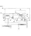
- FIG. 1 is a configuration diagram of a vehicle engine starting device 100 and related devices according to an embodiment of the present invention.
- Engine starter 100 includes a starter 101, a switch 106 for energizing magnet switch 102, a switching element 107 for energizing motor 105, and a control device 109.
- Starter 101 includes a magnet switch 102, a pinion gear 103, and a motor 105.
- the motor 105 is a so-called DC motor, and a rotational driving force is generated by applying a DC voltage.
- the magnet switch 102 pulls the lever 111 when necessary so that the one-way clutch 108 moves on the motor rotation shaft and meshes with the ring gear 104 that is directly connected to the engine shaft.
- the motor 105 is rotated by energizing the motor 105, and the rotational force of the motor 105 is transmitted to the ring gear 104 through the one-way clutch 108, and an engine (not shown) rotates. .
- the control device 109 performs normal fuel injection control, ignition control, air control (electronic control throttle), and controls idle stop based on various information such as brake pedal state and vehicle speed.
- the motor rotation detection sensor 110 detects the rotation of the motor 105. Information on the detected motor rotation speed is input to the control device 109. Instead of directly detecting the rotation of the motor 105 by the motor rotation detection sensor 110, the rotation speed of the motor 105 may be detected indirectly using the engine rotation detected by the engine rotation detection sensor 112.
- the magnet switch 102 is controlled by the control device 109 via the switch 106.
- the switch 106 is, for example, a mechanical relay switch.
- the energization of the motor 105 is also PWM controlled by the control device 109 via the switching element 107.
- the switching element 107 is a switching element using a semiconductor such as a MOSFET, for example.
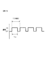
- FIG. 2 is an explanatory diagram of a PWM control energization signal used for energization control for the motor 105 included in the engine starter 100.
- the control device 109 outputs the PWM signal shown in FIG. 2 as an energization signal.
- the switching element 107 performs on / off control of energization to the motor 105.
- the length T of one cycle of the PWM control is 0.1 ms when the frequency of the PWM control is set to 10 KHz, for example.
- the frequency of PWM control is determined so that the control is sufficiently faster than the electric time constant of the motor.
- the energization ratio D in the PWM control is defined as the ratio of the energized section in one cycle.
- the energization ratio D is expressed as a ratio of a section T ON [s] in which the motor is energized in one cycle and the length T [s] of one cycle as in the following equation (1).
- the energization ratio D is a variable whose value can be changed between 0.0 and 1.0.
- the control device 109 controls the energization amount to the motor by changing the energization ratio D.
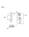
- FIG. 3 shows a simple circuit diagram of the battery 301 and the starter 101.
- many devices are driven by a battery in an automobile, but only a starter 101 including a battery 301 and a motor 105 driven by the battery 301 is shown here.
- Current flowing through the battery 301 (battery current) I b is equal to the motor current I m flowing through the motor 105.
- the output voltage (battery voltage) V b [V] of the battery 301 is determined by the following equation (2).
- the battery voltage V b is because it is determined by the battery current I b, if control of the battery current I b to a predetermined value, the battery voltage V b can be controlled to a predetermined value. If charging of the battery 301 is insufficient, an initial voltage V 0 which battery 301 may be lower than the fully charged state. Further, due to aging of the battery 301 or the like, the internal resistance Rb of the battery 301 may increase, and the battery voltage Vb when the battery current Ib flows may decrease.
- the battery voltage V b decreases even if the same battery current I b flows, and an allowable battery voltage, for example, an electrical component is a battery. It may happen that the operating voltage required to operate in response to the power supply from 301 falls below.
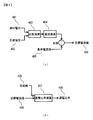
- FIG. 4 is a diagram showing a calculation method of a target current value (described later) of the motor current and a motor energization ratio in the PWM control described above. These calculations are performed by the control device 109.
- the control device 109 acquires a battery voltage V b detected by a battery voltage detection device (not shown) or the like, that is, a detection voltage 401 from the battery voltage detection device or the like. As shown in FIG. 4A, the control device 109 compares the acquired detection voltage 401 with a preset target voltage 402 by a comparison operation 403.
- the target voltage 402 is determined in advance based on the minimum operating voltage of an electrical component or the like, and is stored in the control device 109.
- the control device 109 compares the detection voltage 401 and the target voltage 402, the control device 109 calculates a difference between the two voltage values.
- the current conversion 404 converts the voltage value difference into a current using a predetermined constant, and adds a current proportional to the voltage value difference to the reference current value 405.
- the voltage value difference is a negative value
- the current proportional to the voltage value difference is reduced from the reference current value 405.
- a method of increasing or decreasing the current in proportion to the voltage difference is called so-called proportional control.
- a so-called PID control may be used in which the current is controlled based on the voltage difference and the differential value, or based on the voltage difference and the integral value.
- the predetermined constant used when converting the difference between the voltage values into the current is a feedback gain determined by an experiment, and convergence is slowed down if this is reduced.
- a predetermined conversion table may be used instead of the predetermined constant.
- Reference current value 405 when the difference between the voltage value is not the battery voltage V b by the voltage drop of the battery 301 so as to prevent below the minimum operating voltage, such as electrical components, are set in advance.
- the voltage drop of the battery 301 is caused by supplying a motor current I m (corresponding to the battery current I b ) indicating a current value equal to the target current value 409 from the battery 301 to the motor 105.
- the control device 109 stores the preset reference current value 405 in this way.
- the control device 109 acquires the motor rotation speed of the motor 105 from the motor rotation detection sensor 110.
- the control device 109 controls the switching element 107 so that the current value of the motor current I m (corresponding to the battery current I b ) approaches the target current value 409 based on the motor rotation speed thus obtained and the detection voltage 401.
- the energization ratio to be output is determined by the energization ratio calculation 407 using the information on the motor rotation speed with respect to the target current value 409. Details of the energization ratio calculation 407 will be described with reference to FIG.
- the battery voltage V b [V] is It can be represented by (3).
- Expression (4) corresponds to a state where energization to the motor 105 is continued. According to the research of the inventors of the present invention, it has been found that the current can be approximated by the following equation (5) with respect to the energization ratio D in PWM control. When Expression (5) is used, the current can be controlled to be constant by changing the energization ratio D of the PWM control.
- the current I b flowing through the battery in the PWM control in this embodiment is proportional to the square of the current ratio D.
- the motor current I m flowing through the motor 105 of the starter 101 for equal to the battery current I b
- the motor current I m is the current ratio D when PWM controlling power supply to the DC motor 105 2 It can be approximated to be proportional to the power. This approximation is theoretically determined after experimental observation by the inventors' research.
- Equation (5) is an approximation that is established only in a range in which one cycle of PWM can be regarded as being sufficiently fast with respect to the electric time constant of the motor, and the battery current I b is the constant, the motor rotation speed N m and the energization. It is determined by two variables composed of the ratio D. To reversely use this approximation and determine the energization ratio D so as to obtain a predetermined battery current I b , Equation (5) is transformed into the following Equation (6).
- the battery current I b is set to the target current value 409, and then the energization ratio D is determined by the motor rotation speed N m .
- the energization ratio D calculated by the equation (6) exceeds 1.0, the energization ratio is set to 1.0.
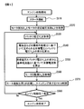
- FIG. 5 is a flowchart showing the contents of the engine start control method performed by the control device 109 in the engine start device 100 according to the present embodiment.
- control device 109 shown in FIG. 1 connects starter 101 and an engine (not shown).
- the pinion gear 103 of FIG. 1 is pushed out and meshed with the ring gear 104 directly connected to the engine.
- the idle stop method in which the starter 101 and the engine are in a connected state is applied, the starter 101 and the engine are already in a connected state when a start request is generated during the idle stop. In that case, the process in step S510 need not be performed.
- step S520 the control unit 109 acquires a counter electromotive voltage coefficient k e of the motor resistance R m and the motor which has been stored in advance.
- step S530 the control unit 109 obtains the battery voltage V b detected by the battery voltage detecting device (not shown) or the like.
- step S540 the controller 109 calculates the difference between the target voltage 402 and the battery voltage V b determined based on the minimum operating voltage, such as electrical equipment.
- step S550 the control device 109 calculates the target current value 409 by the procedure shown in FIG. 4A based on the difference between the target voltage 402 and the battery voltage Vb and the reference current value 405 stored in advance. To do.
- step S560 control device 109 acquires motor rotation speed N m from motor rotation detection sensor 110.
- control device 109 calculates the energization ratio D of PWM control using equation (6) using the variables and constants obtained in the respective processing steps from step S520 to S560, and the waveform of PWM control.
- a signal is output to the switching element 107 to control the switching element 107.
- Current starts to flow to the motor 105 by PWM control of the switching element 107 by the control device 109, torque of the motor 105 is transmitted to the engine, and the engine starts to rotate.
- control device 109 continues the processing in steps 530 to S570 until the engine start completion condition shown in step S580 is satisfied.
- an engine start completion condition in step S580 for example, it is assumed that the engine speed is equal to or higher than a predetermined speed.
- the controller 109 detects the battery voltage V b and the motor rotational speed N m at fixed intervals (e.g., 2ms interval), updates the calculated energization duty D output. By doing this, the battery current is almost constant from the start of motor energization to the completion of engine start, so the battery voltage Vb becomes almost constant because of the set current value, and is kept within the allowable range and close to the allowable value. It is done.
- Many automobiles are equipped with an engine rotation detection sensor 112 for detecting the engine speed, as shown in FIG.
- By indirectly calculating the rotation speed of the motor 105 of the starter 101 from the detected engine rotation speed it is not necessary to mount the motor rotation detection sensor 110, leading to cost reduction.
- the following equation (7) can be used.
- the rotational speed conversion coefficient g in Expression (7) can be obtained from the gear ratio between the engine and the motor 105. Specifically, when the motor 105 and the engine are connected by the pinion gear 103 and the ring gear 104, the gear ratio determined by the number of teeth of the pinion gear 103 and the ring gear 104, and the motor 105 and the pinion gear 103 in the starter 101 If a speed reduction mechanism is provided between the two, the rotation speed conversion coefficient g can be obtained by the speed reduction ratio of the speed reduction mechanism.
- Rotational speed conversion coefficient g is may be stored in advance in the control device 109, converts the sensed engine speed N e by the internal control unit 109 to the motor rotation speed N m.
- a method for estimating the motor speed when a deviation occurs between the calculated value and the actual motor speed when the motor speed is obtained indirectly by calculating from the engine speed will be described.
- Many starters 101 are provided with a one-way clutch 108 while transmitting the rotational force from the motor 105 to an engine (not shown), and are configured to transmit the rotational force only from the starter 101 side.
- the engine can be rotated by the rotational force of the motor 105, but the engine does not rotate the motor 105. Therefore, the motor rotational speed obtained indirectly from the actual motor rotational speed calculated from the engine rotational speed is calculated. May show higher values. At that time, the motor rotation speed is estimated.
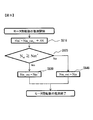
- FIG. 6 is a flowchart showing a procedure for estimating the rotation speed of the motor 105. It is assumed that when the engine speed jumps due to combustion, the clutch is disconnected and the motor 105, which is in an almost no load state, increases its speed at a constant inclination. Under such an assumption, an upper limit is set for the increase in the number of revolutions per control cycle with respect to the indirectly obtained motor revolution number N m , so that the motor revolution number is estimated for a sudden increase in engine revolution.
- the rotation speed N m of the motor is obtained indirectly on the basis of the engine speed N e of engine speed sensor 112 has detected, it allows the rotational speed N m of the motor is deviated from the actual motor speed
- the energization ratio D is calculated using the estimated motor rotation speed Nm_out estimated in consideration of the characteristics. This is repeated for each control period, and the calculation result before one control period is stored in the control device as Nm_out t-1 .
- an upper limit value ⁇ N is set in advance as an upper limit of the increase in the motor rotation speed for each control cycle.
- control device 109 of FIG. 1 adds estimated upper limit value ⁇ N to estimated motor rotation speed Nm_out t ⁇ 1 to newly estimate estimated motor rotation speed as Nm ′.
- the newly estimated estimated motor rotation speed Nm ′ is considered to be the maximum value that can increase within one control period with respect to the estimated motor rotation speed Nm_out t ⁇ 1 one period before.
- step S620 the control unit 109 determines whether compares the indirectly acquired motor rotation speed N m and inferred motor speed Nm', the actual deviation from the motor rotation has occurred. In step S620, when negative determination is made that N m ⁇ Nm ′, control device 109 determines that there is no difference between the indirectly acquired motor rotation speed and the actual motor rotation speed. In step S640, the control unit 109 substitutes the indirectly acquired motor rotation speed N m as it is inferred motor speed Nm_out, using guess motor speed Nm_out the calculation of the energization ratio D.
- step S620 when the determination is positive in Nm ⁇ Nm ′, control device 109 determines that there is a difference between the indirectly acquired motor rotational speed and the actual motor rotational speed. In this case, in step S630, control device 109 substitutes estimated motor rotation speed Nm ′ for estimated motor rotation speed Nm_out, and uses estimated motor rotation speed Nm_out for calculation of energization ratio D. By doing so, the energization ratio D can be calculated correctly even if a deviation occurs from the actual motor speed when the motor speed is calculated indirectly from the engine speed.
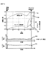
- FIG. 7 is a waveform diagram showing an example of a temporal change in engine start control, in which the engine speed, the energization ratio D output from the control device 109, the battery voltage, and the battery current are associated with temporal changes. Show.
- the energization ratio is calculated using only the engine speed. Since the control device 109 indirectly obtains the motor rotation speed by calculation from the engine rotation speed, the estimation of the motor rotation speed is performed in consideration of the divergence between the estimated motor rotation speed and the actual motor rotation speed. I do.
- a value obtained by converting the motor rotation speed estimated by the control device 109 to the rotation speed on the engine shaft based on the gear ratio between the motor and the engine is indicated by a dotted line 703.
- the battery current 705 at the time of energization is kept almost constant from the start of energization and is kept constant, and is almost the set target current value of the battery current (motor current). Similarly, as shown in FIG.
- the battery voltage 704 at the time of energization is leveled off, and it can be seen that the engine is restarted without falling below the allowable minimum voltage. It is also confirmed that the engine was restarted without falling below the allowable minimum voltage even when the battery deteriorated.
- FIG. 8 is a simple circuit diagram showing the starter 101, the battery 301, and an electric device 803 other than the motor 105 of the starter 101.
- the electric power from the battery 301 is supplied not only to the motor 105 of the starter 101 but also to another electric device 803.
- a method for appropriately changing the motor current flowing through the motor 105 in accordance with the power demand of other electrical equipment other than the motor 105 of the starter 101 will be described.
- the battery current flowing from the battery almost flows into the motor as the motor current.
- the relationship represented by the following equation (8) is established between the total supply current Ie flowing through the device 803.
- the battery current I b is the sum of the supply current I e flowing through the electric devices other than the motor current I m and the motor.
- the battery current I b needs to have a current value that is greater than or equal to the allowable battery current so that the battery voltage V b does not fall below the minimum operating voltage of an electrical component or the like due to a voltage drop of the battery 301.
- the acceptable current value obtained by subtracting the supply current I e from the battery current value motor 105 than other electrical equipment 803, by setting the upper limit value of the motor current I m, is allowed battery current I b in total
- the battery current value is kept constant.
- the supply current I e flowing through the electric device 803 other than the motor 105 is configured to be acquired directly or indirectly.
- the current sensor directly measures the supply current I e flowing through the electric device 803 other than the motor 105, and the control device 109 acquires the measured value from the current sensor.
- Currents normally used by a plurality of electric devices included in other electric devices 803 are individually stored in the control device 109 in advance, and when these electric devices are used, the control device 109 stores the currents.
- the current value of the supply current flowing indirectly through the electric device 803 other than the motor 105 is calculated assuming that the current flows.
- the controller 109 obtains the supply current I e of the other electric devices 803 other than the motor 105 thus, the motor current I m flowing to the motor 105 in order to keep constant the battery current value allowed battery current I b
- the target current value can be calculated.
- the control device 109 calculates the energization ratio D to the motor 105 using the following equation (9).
- the control device 109 acquires the motor rotation speed N m of the motor 105 directly or indirectly.
- the controller 109 may be stored in a controller 109 of the motor rotational speed N m of the motor 105 at the start of the engine model to.
- the controller 109 identifies the appropriate model from among the motor rotation speed N m storage to which the motor 105, selects a motor speed N m corresponding to the identified appropriate model Get by.
- the control device 109 so as to approach the motor current value of the motor current I m to the target current value 409, the motor current I is connected to the motor 105 m controls the switching element 107 to flow.
- a variable resistor may be arranged inside the starter 101 as a circuit element instead of the switching element 107. Controller 109, so as to approach the motor current value of the motor current I m to the target current value 409, to adjust the resistance value of the variable resistor to control the variable resistor is connected to a motor 105 through a motor current I m is.
- the engine starter 100 is an engine starter 101 that starts the engine by transmitting the rotational force of the motor 105 driven by the battery 301 to the engine, and includes a controller 109. .
- the control device 109 acquires the battery voltage V b of the battery 301.
- Controller 109 calculates the target current value 409 of the motor current I m is supplied from the battery 301 to the motor 105.
- Controller 109 so as to approach the motor current value of the motor current I m to the target current value 409, and controls the circuit elements of the switching element 107 or the variable resistor or the like is connected to a motor 105 through a motor current I m is.
- the following effects can be obtained. That is, between the motor energization start until the engine start completion, by maintaining substantially constant for any value of the battery current I b by controlling the motor current I m, it is possible to keep the battery voltage V b is also substantially constant.
- adjustable motor current I m since repeatedly acquires the battery voltage V b to recalculate the target current value in each case the motor current I m, adjustable motor current I m in accordance with a change in the state of the battery 301, such as a sudden voltage drop occurs It is. By doing so, even if the battery state changes, the battery voltage drop remains within the allowable range, and the battery voltage Vb does not fall below the allowable value (minimum operating voltage of electrical components, etc.) when the engine is started. The engine can be started as quickly as possible.
- Controller 109 When the switching element 107 is used as the circuit element, based on the motor rotational speed N m, the controller 109 of the power energization percentage D of the motor 105 by the PWM control is determined. Controller 109, by outputting a PWM control signal for changing the power energization percentage D against the switching element 107 may be a switching element 107, it changes the motor current I m.
- control unit 109 indirectly acquires the rotational speed N m of the motor by calculating from the engine speed N e. In this case, it is not necessary to attach the motor rotation detection sensor 110 for detecting the rotation of the motor 105 to the starter 101, which leads to cost reduction.
- the control device 109 acquires the current I e flowing through another electrical device 803 that uses the same battery 301 as the power source other than the motor 105 so that the battery current I b becomes constant in total.
- the circuit element flowing motor current I m is the voltage drop of the battery 301 even if a large current flows to the other electric devices 803 other than the motor 105 may be suppressed within the allowable range.
Landscapes
- Engineering & Computer Science (AREA)
- Chemical & Material Sciences (AREA)
- Combustion & Propulsion (AREA)
- Mechanical Engineering (AREA)
- General Engineering & Computer Science (AREA)
- Power Engineering (AREA)
- Combined Controls Of Internal Combustion Engines (AREA)
- Control Of Vehicle Engines Or Engines For Specific Uses (AREA)
- Hybrid Electric Vehicles (AREA)
Priority Applications (3)
| Application Number | Priority Date | Filing Date | Title |
|---|---|---|---|
| US14/897,853 US9765745B2 (en) | 2013-06-14 | 2014-05-16 | Engine start-up device, and engine-start-up control method |
| EP14810127.2A EP3009667A4 (en) | 2013-06-14 | 2014-05-16 | Engine start-up device, and engine-start-up control method |
| CN201480033606.3A CN105308307B (zh) | 2013-06-14 | 2014-05-16 | 引擎启动装置以及引擎启动控制方法 |
Applications Claiming Priority (2)
| Application Number | Priority Date | Filing Date | Title |
|---|---|---|---|
| JP2013125867A JP6062324B2 (ja) | 2013-06-14 | 2013-06-14 | エンジン始動装置およびエンジン始動制御方法 |
| JP2013-125867 | 2013-06-14 |
Publications (1)
| Publication Number | Publication Date |
|---|---|
| WO2014199772A1 true WO2014199772A1 (ja) | 2014-12-18 |
Family
ID=52022073
Family Applications (1)
| Application Number | Title | Priority Date | Filing Date |
|---|---|---|---|
| PCT/JP2014/063009 Ceased WO2014199772A1 (ja) | 2013-06-14 | 2014-05-16 | エンジン始動装置およびエンジン始動制御方法 |
Country Status (5)
| Country | Link |
|---|---|
| US (1) | US9765745B2 (https=) |
| EP (1) | EP3009667A4 (https=) |
| JP (1) | JP6062324B2 (https=) |
| CN (1) | CN105308307B (https=) |
| WO (1) | WO2014199772A1 (https=) |
Families Citing this family (7)
| Publication number | Priority date | Publication date | Assignee | Title |
|---|---|---|---|---|
| CN103946604B (zh) * | 2011-11-17 | 2016-03-16 | 丰田自动车株式会社 | 车辆用发动机起动装置 |
| JP6948844B2 (ja) * | 2017-06-06 | 2021-10-13 | 日立Astemo株式会社 | エンジンの始動装置 |
| EP3683913B1 (en) * | 2017-11-22 | 2023-02-22 | GS Yuasa International Ltd. | Restart determination device, internal-short determination device, restart determination method, and computer program |
| JP7010044B2 (ja) * | 2018-02-13 | 2022-01-26 | トヨタ自動車株式会社 | 車両のエンジン始動制御装置 |
| JP7189421B2 (ja) * | 2018-09-21 | 2022-12-14 | ミツミ電機株式会社 | モータ駆動回路及びモータ駆動装置 |
| US12562667B2 (en) | 2020-05-06 | 2026-02-24 | Safran Power Usa, Llc | Starter-generator control unit (SGCU) randomized current feedback control |
| US11732663B2 (en) * | 2020-05-06 | 2023-08-22 | Safran Power Usa, Llc | Starter-generator speed control |
Citations (4)
| Publication number | Priority date | Publication date | Assignee | Title |
|---|---|---|---|---|
| JP2004308645A (ja) * | 2003-03-25 | 2004-11-04 | Denso Corp | エンジン始動装置 |
| JP2005188451A (ja) * | 2003-12-26 | 2005-07-14 | Nippon Soken Inc | エンジン始動制御装置 |
| JP2010106825A (ja) | 2008-10-04 | 2010-05-13 | Denso Corp | エンジン自動停止始動制御装置 |
| WO2013080746A1 (ja) * | 2011-11-29 | 2013-06-06 | 日立オートモティブシステムズ株式会社 | エンジン始動装置および始動方法 |
Family Cites Families (28)
| Publication number | Priority date | Publication date | Assignee | Title |
|---|---|---|---|---|
| JP3746334B2 (ja) * | 1996-08-22 | 2006-02-15 | トヨタ自動車株式会社 | 永久磁石型同期モータの駆動制御装置及び方法 |
| KR100655917B1 (ko) * | 2000-02-28 | 2006-12-08 | 가부시키가이샤 야스가와덴끼 | Pwm 펄스 제어방법 |
| DE10056970A1 (de) * | 2000-11-17 | 2002-05-23 | Bosch Gmbh Robert | Verfahren und Anordnung zur Ermittlung der Startfähigkeit einer Starterbatterie eines Verbrennungsmotors |
| JP2002327668A (ja) * | 2001-04-27 | 2002-11-15 | Toyota Motor Corp | 車両の電池電力配分制御装置 |
| DE102004007393A1 (de) | 2003-02-28 | 2004-09-09 | Denso Corp., Kariya | Maschinenanlasser mit einem Anlassermotor |
| JP4490173B2 (ja) * | 2004-05-31 | 2010-06-23 | 本田技研工業株式会社 | 車両用内燃機関の始動制御装置 |
| JP4622872B2 (ja) * | 2006-01-26 | 2011-02-02 | トヨタ自動車株式会社 | 車両の電源装置、車両および車両の電源装置の制御方法 |
| JP4064428B2 (ja) * | 2006-05-24 | 2008-03-19 | 本田技研工業株式会社 | 内燃機関の制御装置 |
| JP4978429B2 (ja) * | 2007-11-01 | 2012-07-18 | アイシン・エィ・ダブリュ株式会社 | 電動機制御装置,電気自動車およびハイブリッド電気自動車 |
| JP5018516B2 (ja) * | 2008-01-31 | 2012-09-05 | アイシン・エィ・ダブリュ株式会社 | 回転電機制御装置 |
| JP5286981B2 (ja) * | 2008-07-03 | 2013-09-11 | 株式会社ジェイテクト | 電動パワーステアリング装置 |
| JP5195923B2 (ja) * | 2008-12-24 | 2013-05-15 | アイシン・エィ・ダブリュ株式会社 | ハイブリッド駆動装置 |
| JP5165669B2 (ja) * | 2009-12-03 | 2013-03-21 | 日立オートモティブシステムズ株式会社 | エンジン始動装置 |
| JP5482521B2 (ja) * | 2010-02-10 | 2014-05-07 | 株式会社デンソー | スタータ制御装置 |
| JP2011190734A (ja) * | 2010-03-15 | 2011-09-29 | Fujitsu Ten Ltd | アイドリングストップ装置、及び、エンジン始動方法 |
| JP5073007B2 (ja) * | 2010-04-28 | 2012-11-14 | 三菱電機株式会社 | エンジン自動停止再始動装置 |
| CN102959855B (zh) * | 2010-06-25 | 2015-01-21 | 丰田自动车株式会社 | 马达驱动装置和搭载该马达驱动装置的车辆 |
| JP5450311B2 (ja) * | 2010-08-04 | 2014-03-26 | 日立オートモティブシステムズ株式会社 | アイドルストップ制御方法および制御装置 |
| JP5470241B2 (ja) * | 2010-12-28 | 2014-04-16 | 日立オートモティブシステムズ株式会社 | 車両の制御装置 |
| JP5628714B2 (ja) * | 2011-03-11 | 2014-11-19 | 日立オートモティブシステムズ株式会社 | 車両用エンジン始動装置 |
| JP5276697B2 (ja) * | 2011-06-15 | 2013-08-28 | 三菱電機株式会社 | 車載エンジンの始動制御装置 |
| JP5413420B2 (ja) * | 2011-08-08 | 2014-02-12 | 株式会社デンソー | 回転機の制御装置 |
| JP2013151862A (ja) * | 2012-01-24 | 2013-08-08 | Hitachi Koki Co Ltd | エンジン作業機 |
| JP2013194542A (ja) * | 2012-03-16 | 2013-09-30 | Nissan Motor Co Ltd | エンジン始動装置 |
| JP2013209900A (ja) * | 2012-03-30 | 2013-10-10 | Hitachi Automotive Systems Ltd | エンジン始動装置 |
| JP5947705B2 (ja) * | 2012-12-12 | 2016-07-06 | トヨタ自動車株式会社 | 交流電動機の制御システム |
| JP5874688B2 (ja) * | 2013-06-05 | 2016-03-02 | 株式会社デンソー | 制御装置 |
| JP5865930B2 (ja) * | 2014-03-07 | 2016-02-17 | 三菱電機株式会社 | モータ制御装置 |
-
2013
- 2013-06-14 JP JP2013125867A patent/JP6062324B2/ja not_active Expired - Fee Related
-
2014
- 2014-05-16 WO PCT/JP2014/063009 patent/WO2014199772A1/ja not_active Ceased
- 2014-05-16 CN CN201480033606.3A patent/CN105308307B/zh not_active Expired - Fee Related
- 2014-05-16 EP EP14810127.2A patent/EP3009667A4/en not_active Withdrawn
- 2014-05-16 US US14/897,853 patent/US9765745B2/en not_active Expired - Fee Related
Patent Citations (4)
| Publication number | Priority date | Publication date | Assignee | Title |
|---|---|---|---|---|
| JP2004308645A (ja) * | 2003-03-25 | 2004-11-04 | Denso Corp | エンジン始動装置 |
| JP2005188451A (ja) * | 2003-12-26 | 2005-07-14 | Nippon Soken Inc | エンジン始動制御装置 |
| JP2010106825A (ja) | 2008-10-04 | 2010-05-13 | Denso Corp | エンジン自動停止始動制御装置 |
| WO2013080746A1 (ja) * | 2011-11-29 | 2013-06-06 | 日立オートモティブシステムズ株式会社 | エンジン始動装置および始動方法 |
Non-Patent Citations (1)
| Title |
|---|
| See also references of EP3009667A4 * |
Also Published As
| Publication number | Publication date |
|---|---|
| US20160138549A1 (en) | 2016-05-19 |
| EP3009667A4 (en) | 2017-09-20 |
| JP6062324B2 (ja) | 2017-01-18 |
| JP2015001187A (ja) | 2015-01-05 |
| CN105308307B (zh) | 2017-10-31 |
| EP3009667A1 (en) | 2016-04-20 |
| US9765745B2 (en) | 2017-09-19 |
| CN105308307A (zh) | 2016-02-03 |
Similar Documents
| Publication | Publication Date | Title |
|---|---|---|
| JP6062324B2 (ja) | エンジン始動装置およびエンジン始動制御方法 | |
| US10782353B2 (en) | Lithium ion battery residual capacity estimation device | |
| JP2010230654A (ja) | バッテリの状態検出装置 | |
| US8773136B2 (en) | Method for evaluating the ability of a battery to start | |
| US8862365B2 (en) | Vehicular power supply device | |
| JP2004308645A (ja) | エンジン始動装置 | |
| US20140132002A1 (en) | Vehicle power source device | |
| KR102417347B1 (ko) | 마일드 하이브리드 차량의 엔진 시동 방법 및 장치 | |
| CN102251900A (zh) | 发动机起动装置 | |
| JP5761717B2 (ja) | エンジン始動装置および始動方法 | |
| CN105717454B (zh) | 电池监测装置 | |
| US8549939B2 (en) | Start control device | |
| JP4799641B2 (ja) | エンジン始動装置 | |
| JP4869395B2 (ja) | エンジン始動装置 | |
| JP6515786B2 (ja) | エンジンの始動制御装置 | |
| JP5353422B2 (ja) | 車両用発電制御装置 | |
| JP2012228017A (ja) | 発電電動機の制御装置 | |
| JP5282704B2 (ja) | 車両制御装置及び車両制御方法 | |
| JP6667960B2 (ja) | 車両用制御装置 | |
| JP2006180665A (ja) | ハイブリッド車両の充電装置 | |
| CN103154499B (zh) | 用于起动内燃机的方法和装置以及换接装置 | |
| JP7225720B2 (ja) | 回転電機の発電トルク制御装置 | |
| JP6851743B2 (ja) | ジャンピングスタート判定装置 | |
| JP5903328B2 (ja) | エンジン始動装置 | |
| JP5655050B2 (ja) | 発電機の制御装置 |
Legal Events
| Date | Code | Title | Description |
|---|---|---|---|
| WWE | Wipo information: entry into national phase |
Ref document number: 201480033606.3 Country of ref document: CN |
|
| 121 | Ep: the epo has been informed by wipo that ep was designated in this application |
Ref document number: 14810127 Country of ref document: EP Kind code of ref document: A1 |
|
| WWE | Wipo information: entry into national phase |
Ref document number: 14897853 Country of ref document: US |
|
| NENP | Non-entry into the national phase |
Ref country code: DE |
|
| WWE | Wipo information: entry into national phase |
Ref document number: 2014810127 Country of ref document: EP |