WO2014199664A1 - 溶融塩電池 - Google Patents
溶融塩電池 Download PDFInfo
- Publication number
- WO2014199664A1 WO2014199664A1 PCT/JP2014/054152 JP2014054152W WO2014199664A1 WO 2014199664 A1 WO2014199664 A1 WO 2014199664A1 JP 2014054152 W JP2014054152 W JP 2014054152W WO 2014199664 A1 WO2014199664 A1 WO 2014199664A1
- Authority
- WO
- WIPO (PCT)
- Prior art keywords
- salt
- molten salt
- positive electrode
- negative electrode
- cation
- Prior art date
- Legal status (The legal status is an assumption and is not a legal conclusion. Google has not performed a legal analysis and makes no representation as to the accuracy of the status listed.)
- Ceased
Links
Images



Classifications
-
- H—ELECTRICITY
- H01—ELECTRIC ELEMENTS
- H01M—PROCESSES OR MEANS, e.g. BATTERIES, FOR THE DIRECT CONVERSION OF CHEMICAL ENERGY INTO ELECTRICAL ENERGY
- H01M10/00—Secondary cells; Manufacture thereof
- H01M10/05—Accumulators with non-aqueous electrolyte
- H01M10/056—Accumulators with non-aqueous electrolyte characterised by the materials used as electrolytes, e.g. mixed inorganic/organic electrolytes
- H01M10/0564—Accumulators with non-aqueous electrolyte characterised by the materials used as electrolytes, e.g. mixed inorganic/organic electrolytes the electrolyte being constituted of organic materials only
- H01M10/0566—Liquid materials
- H01M10/0569—Liquid materials characterised by the solvents
-
- H—ELECTRICITY
- H01—ELECTRIC ELEMENTS
- H01M—PROCESSES OR MEANS, e.g. BATTERIES, FOR THE DIRECT CONVERSION OF CHEMICAL ENERGY INTO ELECTRICAL ENERGY
- H01M10/00—Secondary cells; Manufacture thereof
- H01M10/05—Accumulators with non-aqueous electrolyte
- H01M10/054—Accumulators with insertion or intercalation of metals other than lithium, e.g. with magnesium or aluminium
-
- H—ELECTRICITY
- H01—ELECTRIC ELEMENTS
- H01M—PROCESSES OR MEANS, e.g. BATTERIES, FOR THE DIRECT CONVERSION OF CHEMICAL ENERGY INTO ELECTRICAL ENERGY
- H01M10/00—Secondary cells; Manufacture thereof
- H01M10/05—Accumulators with non-aqueous electrolyte
- H01M10/056—Accumulators with non-aqueous electrolyte characterised by the materials used as electrolytes, e.g. mixed inorganic/organic electrolytes
- H01M10/0564—Accumulators with non-aqueous electrolyte characterised by the materials used as electrolytes, e.g. mixed inorganic/organic electrolytes the electrolyte being constituted of organic materials only
- H01M10/0566—Liquid materials
- H01M10/0568—Liquid materials characterised by the solutes
-
- H—ELECTRICITY
- H01—ELECTRIC ELEMENTS
- H01M—PROCESSES OR MEANS, e.g. BATTERIES, FOR THE DIRECT CONVERSION OF CHEMICAL ENERGY INTO ELECTRICAL ENERGY
- H01M4/00—Electrodes
- H01M4/02—Electrodes composed of, or comprising, active material
- H01M4/36—Selection of substances as active materials, active masses, active liquids
- H01M4/48—Selection of substances as active materials, active masses, active liquids of inorganic oxides or hydroxides
- H01M4/485—Selection of substances as active materials, active masses, active liquids of inorganic oxides or hydroxides of mixed oxides or hydroxides for inserting or intercalating light metals, e.g. LiTi2O4 or LiTi2OxFy
-
- H—ELECTRICITY
- H01—ELECTRIC ELEMENTS
- H01M—PROCESSES OR MEANS, e.g. BATTERIES, FOR THE DIRECT CONVERSION OF CHEMICAL ENERGY INTO ELECTRICAL ENERGY
- H01M4/00—Electrodes
- H01M4/02—Electrodes composed of, or comprising, active material
- H01M4/36—Selection of substances as active materials, active masses, active liquids
- H01M4/58—Selection of substances as active materials, active masses, active liquids of inorganic compounds other than oxides or hydroxides, e.g. sulfides, selenides, tellurides, halogenides or LiCoFy; of polyanionic structures, e.g. phosphates, silicates or borates
-
- H—ELECTRICITY
- H01—ELECTRIC ELEMENTS
- H01M—PROCESSES OR MEANS, e.g. BATTERIES, FOR THE DIRECT CONVERSION OF CHEMICAL ENERGY INTO ELECTRICAL ENERGY
- H01M4/00—Electrodes
- H01M4/02—Electrodes composed of, or comprising, active material
- H01M4/36—Selection of substances as active materials, active masses, active liquids
- H01M4/58—Selection of substances as active materials, active masses, active liquids of inorganic compounds other than oxides or hydroxides, e.g. sulfides, selenides, tellurides, halogenides or LiCoFy; of polyanionic structures, e.g. phosphates, silicates or borates
- H01M4/5825—Oxygenated metallic salts or polyanionic structures, e.g. borates, phosphates, silicates, olivines
-
- H—ELECTRICITY
- H01—ELECTRIC ELEMENTS
- H01M—PROCESSES OR MEANS, e.g. BATTERIES, FOR THE DIRECT CONVERSION OF CHEMICAL ENERGY INTO ELECTRICAL ENERGY
- H01M4/00—Electrodes
- H01M4/02—Electrodes composed of, or comprising, active material
- H01M4/36—Selection of substances as active materials, active masses, active liquids
- H01M4/58—Selection of substances as active materials, active masses, active liquids of inorganic compounds other than oxides or hydroxides, e.g. sulfides, selenides, tellurides, halogenides or LiCoFy; of polyanionic structures, e.g. phosphates, silicates or borates
- H01M4/583—Carbonaceous material, e.g. graphite-intercalation compounds or CFx
- H01M4/587—Carbonaceous material, e.g. graphite-intercalation compounds or CFx for inserting or intercalating light metals
-
- H—ELECTRICITY
- H01—ELECTRIC ELEMENTS
- H01M—PROCESSES OR MEANS, e.g. BATTERIES, FOR THE DIRECT CONVERSION OF CHEMICAL ENERGY INTO ELECTRICAL ENERGY
- H01M4/00—Electrodes
- H01M4/02—Electrodes composed of, or comprising, active material
- H01M2004/026—Electrodes composed of, or comprising, active material characterised by the polarity
- H01M2004/027—Negative electrodes
-
- H—ELECTRICITY
- H01—ELECTRIC ELEMENTS
- H01M—PROCESSES OR MEANS, e.g. BATTERIES, FOR THE DIRECT CONVERSION OF CHEMICAL ENERGY INTO ELECTRICAL ENERGY
- H01M4/00—Electrodes
- H01M4/02—Electrodes composed of, or comprising, active material
- H01M2004/026—Electrodes composed of, or comprising, active material characterised by the polarity
- H01M2004/028—Positive electrodes
-
- H—ELECTRICITY
- H01—ELECTRIC ELEMENTS
- H01M—PROCESSES OR MEANS, e.g. BATTERIES, FOR THE DIRECT CONVERSION OF CHEMICAL ENERGY INTO ELECTRICAL ENERGY
- H01M2300/00—Electrolytes
- H01M2300/0017—Non-aqueous electrolytes
- H01M2300/0025—Organic electrolyte
- H01M2300/0045—Room temperature molten salts comprising at least one organic ion
-
- Y—GENERAL TAGGING OF NEW TECHNOLOGICAL DEVELOPMENTS; GENERAL TAGGING OF CROSS-SECTIONAL TECHNOLOGIES SPANNING OVER SEVERAL SECTIONS OF THE IPC; TECHNICAL SUBJECTS COVERED BY FORMER USPC CROSS-REFERENCE ART COLLECTIONS [XRACs] AND DIGESTS
- Y02—TECHNOLOGIES OR APPLICATIONS FOR MITIGATION OR ADAPTATION AGAINST CLIMATE CHANGE
- Y02E—REDUCTION OF GREENHOUSE GAS [GHG] EMISSIONS, RELATED TO ENERGY GENERATION, TRANSMISSION OR DISTRIBUTION
- Y02E60/00—Enabling technologies; Technologies with a potential or indirect contribution to GHG emissions mitigation
- Y02E60/10—Energy storage using batteries
Definitions
- the present invention relates to a molten salt battery containing pyrophosphate as a positive electrode active material, and more particularly to a molten salt battery excellent in charge / discharge characteristics at high temperature.
- Non-aqueous electrolyte secondary batteries a lithium ion secondary battery using lithium cobaltate as a positive electrode active material has a high capacity and a high voltage, and its practical use is progressing.
- cobalt and lithium are not only very expensive, but many lithium ion secondary batteries are known to become unstable during overcharge.
- a sodium ion secondary battery using olivine-type sodium iron phosphate (chemical formula NaFePO 4 ), which is cheaper and more stable, is attracting attention.
- pyrophosphate Na 2 FeP 2 O 7 containing sodium twice as much as iron atoms than olivine-type sodium iron phosphate has a high potential, and an improvement in energy density can be expected (Non-patent Document 1).
- molten salt batteries using a flame retardant molten salt electrolyte with excellent thermal stability is also progressing.
- an ionic liquid that is a salt of an organic cation and an anion has been proposed (Patent Document 1).
- An ionic liquid is promising as an electrolyte for a secondary battery because it has a high ionic conductivity, a wide liquid temperature range, a low vapor pressure, and nonflammability.
- a secondary battery using the ionic liquid as an electrolyte can be used at an operating temperature near 100 ° C., for example.
- Non-Patent Document 1 pyrophosphate is promising as a positive electrode active material of a nonaqueous electrolyte secondary battery from the viewpoint of safety and energy density.
- pyrophosphate is promising as a positive electrode active material of a nonaqueous electrolyte secondary battery from the viewpoint of safety and energy density.
- development of non-aqueous electrolyte secondary batteries that can be charged and discharged not only at room temperature but also at a high charge / discharge rate in the temperature range of 50 to 90 ° C, for example. Is desired.
- an electrolyte mainly composed of an organic solvent such as propylene carbonate is used as in Non-Patent Document 1, for example, in the temperature range of about 90 ° C.
- the reaction proceeds violently, making charging and discharging difficult.
- As the charge / discharge rate increases side reactions become more prominent, and gas generation and the accompanying decrease in charge / discharge capacity become more prominent.
- the present invention has the general formula: A n (1-x) M 1 nx Fe 1-y M 2 y P 2 O 7 (n is 1 or 2, 0 ⁇ x ⁇ 0.5,0 ⁇ y ⁇ 0.5, A is an alkali metal element, M 1 is an element other than the element A, and M 2 is an element other than Fe.
- a molten salt battery including the above.
- the molten salt battery of the present invention can be stably charged and discharged even at, for example, 50 to 90 ° C., and can provide a high capacity even when charged and discharged at a high charge and discharge rate.
- FIG. 2 is a sectional view taken along line II-II in FIG. It is a front view of the negative electrode which concerns on one Embodiment of this invention.
- FIG. 4 is a sectional view taken along line IV-IV in FIG. 3. It is the perspective view which notched a part of battery case of the molten salt battery which concerns on one Embodiment of this invention.
- FIG. 6 is a longitudinal sectional view schematically showing a section taken along line VI-VI in FIG. 5.
- 4 is a graph showing charge / discharge curves in the first and second cycles of the coin-type battery of Example 1.
- the positive electrode active material is Na 2-2x M 1 2x Fe 1-y M 2 y P 2 O 7 (0 ⁇ x ⁇ 0.1, 0 ⁇ y ⁇ 0.1, and M 1 is sodium It is preferable that M 2 is an element other than Fe, and the salt of the element A is preferably a sodium salt. Thereby, the molten salt battery excellent in charging / discharging characteristics can be obtained at low cost.
- the positive electrode active material is preferably, for example, Na 2 FeP 2 O 7.
- the molten salt battery excellent in charge / discharge characteristics can be obtained at a lower cost.
- such a positive electrode active material has a simple manufacturing method.
- the ionic liquid has the general formula: [(R 1 SO 2 ) (R 2 SO 2 )] N ⁇ (R 1 and R 2 are each independently F or C n F 2n + 1 , and 1 ⁇ n It is preferable to include a salt of an anion represented by ⁇ 5 and a cation (hereinafter also referred to as a second salt). Thereby, the heat resistance and ionic conductivity of the molten salt battery become more excellent.
- the negative electrode active material is preferably at least one selected from the group consisting of a titanium compound containing element A and non-graphitizable carbon.
- the positive electrode has the general formula: A n (1-x) M 1 nx Fe 1-y M 2 y P 2 O 7 (n is 1 or 2, 0 ⁇ x ⁇ 0.5,0 ⁇ y ⁇ 0
- A is an alkali metal element
- M 1 is an element other than element A
- M 2 is an element other than Fe
- positive electrode active material also referred to as “positive electrode active material”.
- iron pyrophosphate A salt contains a pyrophosphate structure and contains at least an iron atom as a redox center.
- Iron pyrophosphate A salt is considered to have a triclinic crystal structure.
- the degree of freedom of diffusion of the element A becomes very high inside such a crystal structure.
- this tendency is considered to increase as the temperature increases.
- the molten salt electrolyte is stable even at high temperatures and does not decompose due to side reactions. Therefore, even when the molten salt battery is charged / discharged at 50 to 90 ° C., for example, gas generation is suppressed and high capacity can be obtained even when charging / discharging at a high charge / discharge rate.
- the electrolyte which has organic solvents, such as a propylene carbonate as a main component, charging / discharging of a battery at high temperature is very difficult.
- Element A is an alkali metal element, and specific examples include sodium, lithium, potassium, rubidium and cesium. Especially, it is preferable that it is sodium at the point which can obtain the molten salt battery excellent in the charging / discharging characteristic at low cost.
- Element M 1 is an element other than the elements A, for example alkali metal elements other than A.
- the element M 1 can include at least one selected from the group consisting of potassium, cesium, and lithium.
- the element M 1 is an element that occupies a site that is crystallographically equivalent to the site that the element A occupies.
- Elements M 2 is an element other than Fe, specifically, Cr, Mn, or Ni and Co and the like. Especially, Mn is preferable at the point with the reversibility of charging / discharging.
- the element M 2 may include one kind alone or a plurality of kinds.
- Elements M 2 is an element occupying the site crystallographically equivalent sites Fe occupied.
- x is a number satisfying 0 ⁇ x ⁇ 0.5, and preferably 0 ⁇ x ⁇ 0.1.
- y is a number satisfying 0 ⁇ y ⁇ 0.5, and preferably 0 ⁇ y ⁇ 0.1. If y becomes too large, the reversibility of charge / discharge tends to decrease.
- positive electrode active material represented by A n (1-x) M 1 nx Fe 1-y M 2 y P 2 O 7 which may be used alone, in combination of plural kinds It may be used.
- Preferred iron pyrophosphate A salts are of the general formula Na 2-2x M 1 2x Fe 1-y M 2 y P 2 O 7 (0 ⁇ x ⁇ 0.1, 0 ⁇ y ⁇ 0.1, where M 1 is And M 2 is an element other than Fe).
- the molten salt electrolyte contains 90% by mass or more of an ionic liquid containing a sodium salt.
- iron pyrophosphate A salt is preferably a Na 2 FeP 2 O 7.
- the molten salt battery excellent in charge / discharge characteristics can be obtained at a lower cost.
- such a positive electrode active material has a simple manufacturing method.
- the positive electrode active material may contain an alkali metal-containing metal oxide that is a material that electrochemically occludes and releases alkali metal ions other than the iron pyrophosphate A salt.
- sodium-containing metal oxides include sodium chromite (NaCrO 2 ), sodium iron manganate (Na 2/3 Fe 1/3 Mn 2/3 O 2, etc.), Na 2 FePO 4 F, NaVPO 4 F NaCoPO 4 , NaNiPO 4 , NaMnPO 4 , NaMn 1.5 Ni 0.5 O 4 , NaMn 0.5 Ni 0.5 O 2 and the like.
- One or more alkali metal-containing metal oxides may be used in combination.
- the average particle diameter of the positive electrode active material is preferably 2 ⁇ m or more and 20 ⁇ m or less. Within such a particle size range, it is easy to form a homogeneous positive electrode active material layer, and the electrode reaction also proceeds smoothly.
- the average particle diameter is a median diameter in a volume particle size distribution obtained by a laser diffraction particle size distribution measuring apparatus.
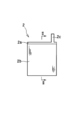
- FIG. 1 is a front view of a positive electrode according to an embodiment of the present invention
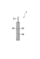
- FIG. 2 is a cross-sectional view taken along the line II-II in FIG.
- the positive electrode 2 for a molten salt battery includes a positive electrode current collector 2a and a positive electrode active material layer 2b attached to the positive electrode current collector 2a.
- the positive electrode active material layer 2b includes a positive electrode active material as an essential component, and may include a conductive carbon material, a binder, and the like as optional components.
- Examples of the conductive carbon material included in the positive electrode include graphite, carbon black, and carbon fiber.
- carbon black is particularly preferable because it can easily form a sufficient conductive path when used in a small amount.
- Examples of carbon black include acetylene black, ketjen black, and thermal black.
- the amount of the conductive carbon material is preferably 2 to 15 parts by mass and more preferably 3 to 8 parts by mass per 100 parts by mass of the positive electrode active material.
- the binder serves to bond the positive electrode active materials to each other and fix the positive electrode active material to the positive electrode current collector.
- fluorine resin polyamide, polyamide, polyamide amide, or the like can be used.
- fluororesin polyvinylidene fluoride (PVDF), polytetrafluoroethylene (PTFE), tetrafluoroethylene-hexafluoropropylene copolymer, vinylidene fluoride-hexafluoropropylene copolymer, and the like can be used.
- the amount of the binder is preferably 1 to 10 parts by weight and more preferably 3 to 5 parts by weight per 100 parts by weight of the positive electrode active material.
- the positive electrode current collector 2a a metal foil, a non-woven fabric made of metal fibers, a porous metal sheet, or the like is used.
- the metal constituting the positive electrode current collector is preferably aluminum or an aluminum alloy because it is stable at the positive electrode potential, but is not particularly limited. When using an aluminum alloy, it is preferable that metal components (for example, Fe, Si, Ni, Mn, etc.) other than aluminum are 0.5 mass% or less.
- the thickness of the metal foil serving as the positive electrode current collector is, for example, 10 to 50 ⁇ m, and the thickness of the metal fiber nonwoven fabric or the metal porous sheet is, for example, 100 to 600 ⁇ m.
- a positive electrode lead piece 2c for current collection may be formed on the positive electrode current collector 2a. As shown in FIG. 1, the positive electrode lead piece 2c may be formed integrally with the positive electrode current collector, or a separately formed lead piece may be connected to the positive electrode current collector by welding or the like.
- the molten salt electrolyte contains 90% by mass or more of an ionic liquid containing a salt of the element A (first salt).
- the ionic liquid should just be a liquid in the operating temperature range of a molten salt battery.
- the molten salt electrolyte is advantageous in that it has high heat resistance and nonflammability. Therefore, it is desirable that the molten salt electrolyte does not contain components other than the ionic liquid as much as possible.
- the molten salt electrolyte may contain various additives and organic solvents in amounts that do not significantly impair the heat resistance and nonflammability. In order not to impair heat resistance and incombustibility, it is preferable that 95 to 100% by mass of the molten salt electrolyte is occupied by the ionic liquid containing the first salt.
- the first salt is a salt of an alkali metal cation, which is the element A, and an anion.
- the anion is preferably a polyatomic anion.
- a bis (sulfonyl) amide anion is preferable in terms of heat resistance and ion conductivity of the molten salt battery.
- bis (sulfonyl) amide anion examples include bis (fluorosulfonyl) amide anion, (fluorosulfonyl) (perfluoroalkylsulfonyl) amide anion, and bis (perfluoroalkylsulfonyl) amide anion (PFSA ⁇ : bis (Pentafluoroethylsulfimide) imide anion).
- the carbon number of the perfluoroalkyl group is, for example, 1 to 5, preferably 1 to 2, and more preferably 1.
- bis (sulfonyl) amide anions bis (fluorosulfonyl) amide anions (FSA ⁇ : bis (fluorosulfonyl) amide anion)); bis (trifluoromethylsulfonyl) amide anions (TFSA ⁇ : bis (trifluoromethylsulfonyl) amide) anion), bis (pentafluoroethylsulfonyl) amide anion, (fluorosulfonyl) (trifluoromethylsulfonyl) amide anion and the like are preferable.
- the first salt examples include a salt of sodium ion and FSA ⁇ (Na ⁇ FSA) and a salt of sodium ion and TFSA ⁇ (Na ⁇ TFSA) when the element A is sodium.
- the ionic liquid may be composed only of the first salt.
- the ionic liquid is preferably a mixture with a salt other than the first salt.
- the ionic liquid contains a salt (second salt) of an anion such as PF 6 ⁇ , BF 4 ⁇ , ClO 4 ⁇ or bis (sulfonyl) amide anion and a cation as a salt other than the first salt.
- a salt (second salt) of an anion such as PF 6 ⁇ , BF 4 ⁇ , ClO 4 ⁇ or bis (sulfonyl) amide anion and a cation as a salt other than the first salt.
- a bis (sulfonyl) amide anion is preferable.
- the compounds listed above can be exemplified.
- Examples of the cation of the second salt include organic cations and alkali metal cations other than element A.
- organic cations include nitrogen-containing cations; sulfur-containing cations; phosphorus-containing cations.
- Nitrogen-containing cations include cations derived from aliphatic amines, alicyclic amines, and aromatic amines (for example, quaternary ammonium cations), and organic cations having nitrogen-containing heterocycles (that is, cyclic amines). Examples thereof include derived cations).
- Examples of the quaternary ammonium cation include tetramethylammonium cation, ethyltrimethylammonium cation, hexyltrimethylammonium cation, ethyltrimethylammonium cation (TEA + : ethyltrimethylammonium cation), methyltriethylammonium cation (TEMA + : methyltriethylammonium cation), and the like.
- Examples thereof include a tetraalkylammonium cation (such as a tetra C 1-10 alkylammonium cation).
- sulfur-containing cation examples include tertiary sulfonium cations such as trialkylsulfonium cations such as trimethylsulfonium cation, trihexylsulfonium cation, and dibutylethylsulfonium cation (for example, tri-C 1-10 alkylsulfonium cation). .
- tertiary sulfonium cations such as trialkylsulfonium cations such as trimethylsulfonium cation, trihexylsulfonium cation, and dibutylethylsulfonium cation (for example, tri-C 1-10 alkylsulfonium cation).
- Phosphorus-containing cations include quaternary phosphonium cations, for example, tetraalkylphosphonium cations such as tetramethylphosphonium cation, tetraethylphosphonium cation, tetraoctylphosphonium cation (for example, tetra C 1-10 alkylphosphonium cation); triethyl (methoxymethyl) ) Alkyl (alkoxyalkyl) phosphonium cations such as phosphonium cation, diethylmethyl (methoxymethyl) phosphonium cation, trihexyl (methoxyethyl) phosphonium cation (eg, tri-C 1-10 alkyl (C 1-5 alkoxy C 1-5 alkyl)) Phosphonium cation, etc.).
- tetraalkylphosphonium cations such as tetramethylphosphonium cation, te
- the total number of alkyl groups and alkoxyalkyl groups bonded to the phosphorus atom is 4, and the number of alkoxyalkyl groups is preferably 1 or 2.
- the number of carbon atoms of the alkyl group bonded to the nitrogen atom of the quaternary ammonium cation, the sulfur atom of the tertiary sulfonium cation, or the phosphorus atom of the quaternary phosphonium cation is preferably 1 to 8, more preferably 1 to 4. 1, 2, or 3 is particularly preferable.
- the organic cation is preferably an organic cation having a nitrogen-containing heterocycle.
- An ionic liquid having an organic cation having a nitrogen-containing heterocycle is promising as a molten salt electrolyte because of its high heat resistance and low viscosity.
- the nitrogen-containing heterocyclic skeleton of the organic cation include pyrrolidine, imidazoline, imidazole, pyridine, piperidine, and the like, 5- to 8-membered heterocycles having 1 or 2 nitrogen atoms as ring members; Examples thereof include 5- to 8-membered heterocycles having 1 or 2 nitrogen atoms and other heteroatoms (oxygen atoms, sulfur atoms, etc.).
- the nitrogen atom which is a constituent atom of the ring may have an organic group such as an alkyl group as a substituent.
- alkyl group examples include alkyl groups having 1 to 10 carbon atoms such as a methyl group, an ethyl group, a propyl group, and an isopropyl group.
- the alkyl group preferably has 1 to 8 carbon atoms, more preferably 1 to 4 carbon atoms, and particularly preferably 1, 2 or 3.
- organic cations having a nitrogen-containing heterocycle are particularly promising as molten salt electrolytes because of their high heat resistance and low production costs.
- the organic cation having a pyrrolidine skeleton preferably has two of the above alkyl groups on one nitrogen atom constituting the pyrrolidine ring.
- the organic cation having a pyridine skeleton preferably has one alkyl group on one nitrogen atom constituting the pyridine ring.
- the organic cation having an imidazoline skeleton preferably has one of the above alkyl groups on each of two nitrogen atoms constituting the imidazoline ring.
- organic cation having a pyrrolidine skeleton examples include 1,1-dimethylpyrrolidinium cation, 1,1-diethylpyrrolidinium cation, 1-ethyl-1-methylpyrrolidinium cation, 1-methyl-1- Propylpyrrolidinium cation (MPPY + : 1-methyl-1-pyrrolidinium cation), 1-methyl-1-butylpyrrolidinium cation (MBPY + : 1-butyl-1-methylpyrrolidinium cation), 1-ethyl-1- And propylpyrrolidinium cation.
- pyrrolidinium cations having a methyl group and an alkyl group having 2 to 4 carbon atoms such as MPPY + and MBPY +, are preferable because of particularly high electrochemical stability.
- organic cation having a pyridine skeleton examples include 1-alkylpyridinium cations such as 1-methylpyridinium cation, 1-ethylpyridinium cation, and 1-propylpyridinium cation. Of these, pyridinium cations having an alkyl group having 1 to 4 carbon atoms are preferred.
- organic cation having an imidazoline skeleton examples include 1,3-dimethylimidazolium cation, 1-ethyl-3-methylimidazolium cation (EMI + : 1-ethyl-3-methylimidazolium cation), 1-methyl-3 -Propylimidazolium cation, 1-butyl-3-methylimidazolium cation (BMI + : 1-butyl-3-imidazolium cation), 1-ethyl-3-propylimidazolium cation, 1-butyl-3-ethylimidazolium And cations.
- EMI + 1-ethyl-3-methylimidazolium cation
- BMI + 1-butyl-3-imidazolium cation
- 1-ethyl-3-propylimidazolium cation 1-butyl-3-ethylimidazolium And cations.
- the concentration of the element A contained in the molten salt electrolyte (first If the mono-salt is a monovalent salt, it is synonymous with the concentration of the first salt) is preferably 2 mol% or more of the cation contained in the molten salt electrolyte, more preferably 5 mol% or more, It is particularly preferably 8 mol% or more.
- the concentration of element A is preferably 30 mol% or less, more preferably 20 mol% or less, and particularly preferably 15 mol% or less of the cation contained in the molten salt electrolyte.
- Such a molten salt electrolyte has a high content of the second salt and a low viscosity, and is advantageous in achieving a high capacity, particularly when charging / discharging at a high rate of current.
- the preferable upper limit and lower limit of the concentration of the element A can be arbitrarily combined to set a preferable range.
- the preferable range of the concentration of the element A with respect to the whole cation contained in the molten salt electrolyte may be 2 to 20 mol% or 5 to 15 mol%.
- the molar ratio (first salt / second salt) between the first salt and the second salt which is a salt of the organic cation and the anion is, for example, 2 / 98 to 20/80, and preferably 5/95 to 15/85.
- alkali metal cations other than element A used as the cation of the second salt include sodium, lithium, potassium, rubidium and cesium.
- the cation of the second salt is a potassium ion, a cesium ion, a lithium ion, or the like.
- a cation may be used individually by 1 type, and may use 2 or more types.
- the element contained in the molten salt electrolyte contains 90% by mass or more of a mixture of the first salt and the second salt, and the second salt is a salt of an alkali metal cation other than the element A and an anion
- the element contained in the molten salt electrolyte The concentration of A (synonymous with the concentration of the first salt if the first salt is a monovalent salt) is preferably 30 mol% or more of the cation contained in the molten salt electrolyte, and is 40 mol% or more. More preferably.
- the concentration of element A is preferably 70 mol% or less, more preferably 60 mol% or less of the cation contained in the molten salt electrolyte.
- Such a molten salt electrolyte has excellent ionic conductivity, and it is easy to achieve a high capacity when charging / discharging at a high rate of current.
- the preferable upper limit and lower limit of the concentration of the element A can be arbitrarily combined to set a preferable range.
- a preferable range of the concentration of the element A in the entire cation contained in the molten salt electrolyte may be 30 to 70 mol% or 40 to 60 mol%.
- the molar ratio of the first salt / second salt takes into account the balance of the melting point, viscosity, and ionic conductivity of the electrolyte. For example, it is preferably 45/55 to 65/35, and more preferably 50/50 to 60/40.
- the second salt examples include a salt of MPPY + and FSA ⁇ (MPPY ⁇ FSA), a salt of MPPY + and TFSA ⁇ (MPPY ⁇ TFSA), and a salt of potassium ion and FSA ⁇ (K ⁇ FSA). , potassium bis (trifluoromethylsulfonyl) amide (K ⁇ TFSA) potassium ion to PFSA such - salts with (K ⁇ PFSA) and the like.
- molten salt electrolyte As a specific example of the molten salt electrolyte, (I) a molten salt electrolyte containing a salt of sodium ion and FSA ⁇ as the first salt (Na ⁇ FSA) and a salt of MPPY + and FSA ⁇ (MPPY ⁇ FSA) as the second salt; (Ii) a molten salt electrolyte containing a salt of sodium ion and TFSA ⁇ as a first salt (Na ⁇ TFSA) and a salt of MPPY + and TFSA ⁇ (MPPY ⁇ TFSA) as a second salt; (Iii) a molten salt electrolyte containing a salt of sodium ion and FSA ⁇ (Na ⁇ FSA) as the first salt and a salt of potassium ion and FSA ⁇ (K ⁇ FSA) as the second salt; (Iv) A molten salt electrolyte containing a salt of
- the type of salt constituting the ionic liquid is not limited to one or two.
- the ionic liquid may contain three or more kinds of salts.
- the molten salt electrolyte may include 90% by mass or more of a mixture of a first salt, a second salt, and a third salt, and the molten salt electrolyte includes four or more kinds of salts including a first salt to a third salt. It may be a mixture.
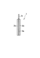
- FIG. 3 is a front view of a negative electrode according to an embodiment of the present invention
- FIG. 4 is a cross-sectional view taken along line IV-IV in FIG.
- the negative electrode 3 includes a negative electrode current collector 3a and a negative electrode active material layer 3b attached to the negative electrode current collector 3a.
- a metal foil, a non-woven fabric made of metal fibers, a porous metal sheet, or the like is used.
- the metal a metal that is not alloyed with sodium can be used.
- aluminum, an aluminum alloy, copper, a copper alloy, nickel, a nickel alloy, and the like are preferable because they are stable at the negative electrode potential. Of these, aluminum and aluminum alloys are preferable in terms of excellent lightness.
- the aluminum alloy for example, an aluminum alloy similar to that exemplified as the positive electrode current collector may be used.
- the thickness of the metal foil serving as the negative electrode current collector is, for example, 10 to 50 ⁇ m, and the thickness of the metal fiber non-woven fabric or metal porous sheet is, for example, 100 to 600 ⁇ m.
- a negative electrode lead piece 3c for current collection may be formed on the negative electrode current collector 3a. As shown in FIG. 3, the negative electrode lead piece 3c may be formed integrally with the negative electrode current collector, or a separately formed lead piece may be connected to the negative electrode current collector by welding or the like.
- the negative electrode active material layer 3b a metal that can be alloyed with an alkali metal or a material that electrochemically occludes and releases alkali metal cations can be used as the negative electrode active material.
- the metal alloyed with sodium includes metal sodium, sodium alloy, zinc, zinc alloy, tin, tin alloy, silicon, silicon alloy and the like. Of these, zinc and zinc alloys are preferred in terms of good wettability with respect to the molten salt.
- the thickness of the negative electrode active material layer is preferably 0.05 to 1 ⁇ m, for example.
- metal components for example, Fe, Ni, Si, Mn, etc.
- metal components for example, Fe, Ni, Si, Mn, etc.
- zinc or tin in a zinc alloy or a tin alloy shall be 0.5 mass% or less.
- the negative electrode active material layer 3b can be obtained, for example, by attaching a metal sheet to the negative electrode current collector 3a or by pressure bonding.
- the metal may be gasified and attached to the negative electrode current collector by a vapor phase method such as vacuum deposition or sputtering, or the metal fine particles may be collected by an electrochemical method such as plating. You may make it adhere to an electric body.
- a vapor phase method or the plating method a thin and uniform negative electrode active material layer can be formed.
- element A-containing titanium compounds As the material that electrochemically occludes and releases alkali metal cations, element A-containing titanium compounds, non-graphitizable carbon (hard carbon) and the like are preferable from the viewpoints of thermal stability and electrochemical stability.
- an alkali metal titanate is preferable.
- at least one selected from the group consisting of Na 2 Ti 3 O 7 and Na 4 Ti 5 O 12 is preferably used. .
- M 5 and M 6 are each independently a metal element other than Ti and Na, and is at least one selected from the group consisting of Ni, Co, Mn, Fe, Al, and Cr, for example.
- Na 4 ⁇ x M 7 x Ti 5 ⁇ y M 8 y O 12 can be used.
- M 7 and M 8 are each independently a metal element other than Ti and Na, and is at least one selected from the group consisting of Ni, Co, Mn, Fe, Al, and Cr, for example.
- An element A containing titanium compound may be used individually by 1 type, and may be used in combination of multiple types. The element A-containing titanium compound may be used in combination with non-graphitizable carbon.
- M 5 and M 7 are Na sites, and M 6 and M 8 are elements occupying Ti sites.
- Non-graphitizable carbon is a carbon material that does not develop a graphite structure even when heated in an inert atmosphere. Fine graphite crystals are arranged in random directions, and nanostructured between crystal layers. A material having a void in the order. Since the diameter of a typical alkali metal sodium ion is 0.95 angstrom, the size of the void is preferably sufficiently larger than this.
- the average particle diameter of the non-graphitizable carbon (the particle diameter D50 at a cumulative volume of 50% of the volume particle size distribution) may be, for example, 3 to 20 ⁇ m, and 5 to 15 ⁇ m. It is desirable from the viewpoint of enhancing the pH and suppressing side reactions with the electrolyte (molten salt).
- the specific surface area of the non-graphitizable carbon, along with ensuring the acceptance of the sodium ions, from the viewpoint of suppressing side reactions with the electrolyte, for example, may be a 1 ⁇ 10m 2 / g, 3 ⁇ 8m 2 / It is preferable that it is g.
- Non-graphitizable carbon may be used alone or in combination of two or more.
- the negative electrode active material layer 3b may be a mixture layer that includes the negative electrode active material active material as an essential component and includes a binder, a conductive material, and the like as optional components.
- the binder and the conductive material used for the negative electrode the materials exemplified as the constituent elements of the positive electrode can be used.
- the amount of the binder is preferably 1 to 10 parts by mass and more preferably 3 to 5 parts by mass per 100 parts by mass of the negative electrode active material.
- the amount of the conductive material is preferably 5 to 15 parts by mass and more preferably 5 to 10 parts by mass per 100 parts by mass of the negative electrode active material.
- the negative electrode current collector 3a formed of aluminum or an aluminum alloy, and zinc, zinc alloy, tin or tin alloy covering at least part of the surface of the negative electrode current collector were formed.
- a negative electrode including the negative electrode active material layer 3b can be exemplified. Such a negative electrode has a high capacity and is unlikely to deteriorate over a long period of time.
- a separator can be disposed between the positive electrode and the negative electrode.
- the material of the separator may be selected in consideration of the operating temperature of the battery, but from the viewpoint of suppressing side reactions with the molten salt electrolyte, glass fiber, silica-containing polyolefin, fluororesin, alumina, polyphenylene sulfite (PPS) Etc.) are preferably used.
- a glass fiber nonwoven fabric is preferable because it is inexpensive and has high heat resistance.
- Silica-containing polyolefin and alumina are preferable in terms of excellent heat resistance.
- a fluororesin and PPS are preferable in terms of heat resistance and corrosion resistance. In particular, PPS has excellent resistance to fluorine contained in the molten salt.
- the thickness of the separator is preferably 10 ⁇ m to 500 ⁇ m, more preferably 20 to 50 ⁇ m. If the thickness is within this range, an internal short circuit can be effectively prevented, and the volume occupancy of the separator in the electrode group can be kept low, so that a high capacity density can be obtained.
- the molten salt battery is used in a state where the electrode group including the positive electrode and the negative electrode and the molten salt electrolyte are accommodated in a battery case.
- the electrode group is formed by laminating or winding a positive electrode and a negative electrode with a separator interposed therebetween.
- a metal battery case by making one of the positive electrode and the negative electrode conductive with the battery case, a part of the battery case can be used as the first external terminal.
- the other of the positive electrode and the negative electrode is connected to a second external terminal led out of the battery case in a state insulated from the battery case, using a lead piece or the like.
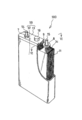
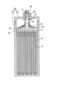
- FIG. 5 is a perspective view of the molten salt battery 100 with a part of the battery case cut away
- FIG. 6 is a longitudinal sectional view schematically showing a cross section taken along line VI-VI in FIG.
- the molten salt battery 100 includes a laminated electrode group 11, an electrolyte (not shown), and a rectangular aluminum battery case 10 that houses them.
- the battery case 10 includes a bottomed container body 12 having an upper opening and a lid 13 that closes the upper opening.
- a step of injecting a molten salt electrolyte into the container body 12 and impregnating the molten salt electrolyte into the gaps of the separator 1, the positive electrode 2 and the negative electrode 3 constituting the electrode group 11 is performed.
- the molten salt electrolyte may be impregnated with the electrode group 11, and then the electrode group 11 including the molten salt electrolyte may be accommodated in the container body 12.
- An external positive terminal 14 that penetrates the lid 13 while being insulated from the battery case 10 is provided near one side of the lid 13, and is electrically connected to the battery case 10 at a position near the other side of the lid 13. In this state, an external negative electrode terminal 15 that penetrates the lid portion 13 is provided. In the center of the lid portion 13, a safety valve 16 is provided for releasing gas generated inside when the internal pressure of the battery case 10 rises.
- the stacked electrode group 11 is composed of a plurality of positive electrodes 2, a plurality of negative electrodes 3, and a plurality of separators 1 interposed between them, each having a rectangular sheet shape.
- the separator 1 is formed in a bag shape so as to surround the positive electrode 2, but the form of the separator is not particularly limited.
- the plurality of positive electrodes 2 and the plurality of negative electrodes 3 are alternately arranged in the stacking direction in the electrode group 11.
- a positive electrode lead piece 2 c may be formed at one end of each positive electrode 2.
- the plurality of positive electrodes 2 are connected in parallel by bundling the positive electrode lead pieces 2 c of the plurality of positive electrodes 2 and connecting them to the external positive terminal 14 provided on the lid portion 13 of the battery case 10.
- a negative electrode lead piece 3 c may be formed at one end of each negative electrode 3.
- the plurality of negative electrodes 3 are connected in parallel by bundling the negative electrode lead pieces 3 c of the plurality of negative electrodes 3 and connecting them to the external negative terminal 15 provided on the lid portion 13 of the battery case 10.
- the bundle of the positive electrode lead pieces 2c and the bundle of the negative electrode lead pieces 3c are desirably arranged on the left and right sides of one end face of the electrode group 11 so as to avoid mutual contact.
- the external positive terminal 14 and the external negative terminal 15 are both columnar, and at least a portion exposed to the outside has a screw groove.
- a nut 7 is fitted in the screw groove of each terminal, and the nut 7 is fixed to the lid portion 13 by rotating the nut 7.
- a flange portion 8 is provided in a portion of each terminal accommodated in the battery case, and the flange portion 8 is fixed to the inner surface of the lid portion 13 via a washer 9 by the rotation of the nut 7.
- Example 1 (Synthesis of positive electrode active material) Na 2 CO 3 , FeC 2 O 4 .2H 2 O and (NH 4 ) 2 HPO 4 were mixed in acetone by a planetary ball mill for 8 hours. The obtained mixture was heat-treated in argon at 300 ° C. for 6 hours and then calcined at 600 ° C. for 12 hours to obtain Na 2 FeP 2 O 7 .
- a metal sodium disk (Aldrich, thickness: 200 ⁇ m) was pressure-bonded to a nickel current collector to produce a negative electrode having a total thickness of 700 ⁇ m.
- the negative electrode was punched into a coin shape having a diameter of 12 mm.
- Separator A separator made of glass microfiber (manufactured by Whatman, grade GF / A, thickness 260 ⁇ m) was prepared.
- the coin-type positive electrode, negative electrode, and separator were sufficiently dried by heating at 90 ° C. or higher under a reduced pressure of 0.3 Pa. Thereafter, a coin-type negative electrode is placed on a shallow cylindrical Al / SUS clad container, and a coin-type positive electrode is placed thereon via a coin-type separator, and a predetermined amount of molten salt electrolyte is placed. Was poured into the container. Thereafter, the opening of the container was sealed with a shallow cylindrical Al / SUS clad sealing plate having an insulating gasket on the periphery.
- Comparative Example 1 A coin-type battery was fabricated in the same manner as in Example 1 except that a propylene carbonate solution containing NaClO 4 at a concentration of 1 mol / L was used as the electrolyte.
- a capacity of about 90 mAh / g was obtained at a current density of 5 mA / g, a capacity of about 80 mAh / g at a current density of 500 mA / g, and a high discharge capacity of about 60 mAh / g at a current density of 2000 mA / g.
- the molten salt battery according to the present invention is excellent in charge / discharge cycle characteristics, it is used as a power source for applications requiring long-term reliability, for example, large power storage devices for home use or industrial use, electric vehicles, hybrid vehicles, etc. Useful.
Landscapes
- Chemical & Material Sciences (AREA)
- General Chemical & Material Sciences (AREA)
- Chemical Kinetics & Catalysis (AREA)
- Electrochemistry (AREA)
- Inorganic Chemistry (AREA)
- Engineering & Computer Science (AREA)
- Manufacturing & Machinery (AREA)
- General Physics & Mathematics (AREA)
- Condensed Matter Physics & Semiconductors (AREA)
- Physics & Mathematics (AREA)
- Crystallography & Structural Chemistry (AREA)
- Materials Engineering (AREA)
- Secondary Cells (AREA)
- Battery Electrode And Active Subsutance (AREA)
Abstract
Description
最初に発明の実施形態の要旨を列記して説明する。
(1)本実施形態は、一般式:An(1-x)M1 nxFe1-yM2 yP2O7(nは、1または2であり、0≦x≦0.5、0≦y≦0.5であり、Aは、アルカリ金属元素であり、M1は、元素A以外の元素であり、M2は、Fe以外の元素である)で表される正極活物質を含む正極と、負極活物質を含む負極と、前記正極と前記負極との間に介在するセパレータと、溶融塩電解質と、を含み、前記溶融塩電解質は、元素Aの塩(以下、第一塩とも称する)を含むイオン液体を90質量%以上含む、溶融塩電池に関する。上記構成によれば、溶融塩電池を、例えば50~90℃でも安定に充放電可能であり、かつ高い充放電レートで充放電しても高容量が得られる。
本発明の実施形態の具体例を以下に説明する。なお、本発明は、これらの例示に限定されるものではなく、特許請求の範囲によって示され、特許請求の範囲と均等の意味および範囲内でのすべての変更が含まれることが意図される。
正極は、一般式:An(1-x)M1 nxFe1-yM2 yP2O7(nは、1または2であり、0≦x≦0.5、0≦y≦0.5である。ここで、Aは、アルカリ金属元素であり、M1は、元素A以外の元素であり、M2は、Fe以外の元素である)で表される正極活物質(以下、ピロリン酸鉄A塩とも称する)を含む。ピロリン酸鉄A塩は、ピロリン酸構造を含み、酸化還元中心として、少なくとも鉄原子を含んでいる。nは、1または2であればよいが、n=2であることが、高容量を得る観点からは好ましい。n=2のとき、充放電に伴い、鉄原子の価数は、2価と3価の間で変化する。
溶融塩電池用の正極2は、正極集電体2aおよび正極集電体2aに付着した正極活物質層2bを含む。正極活物質層2bは、正極活物質を必須成分として含み、任意成分として導電性炭素材料、結着剤等を含んでもよい。
溶融塩電解質は、元素Aの塩(第一塩)を含むイオン液体を90質量%以上含む。イオン液体は、溶融塩電池の作動温度域で液体であればよい。溶融塩電解質は、耐熱性が高く、不燃性を有する点にメリットがある。よって、溶融塩電解質は、イオン液体以外の成分を極力含まないことが望ましい。ただし、耐熱性および不燃性を大きく損なわない量の様々な添加剤や有機溶媒を溶融塩電解質に含ませることもできる。耐熱性および不燃性を損なわないように、溶融塩電解質の95~100質量%が、第一塩を含むイオン液体により占められていることが好ましい。
(i)第一塩として、ナトリウムイオンとFSA-との塩(Na・FSA)を含み、第二塩として、MPPY+とFSA-との塩(MPPY・FSA)を含む溶融塩電解質、
(ii)第一塩として、ナトリウムイオンとTFSA-との塩(Na・TFSA)を含み、第二塩として、MPPY+とTFSA-との塩(MPPY・TFSA)を含む溶融塩電解質、
(iii)第一塩として、ナトリウムイオンとFSA-との塩(Na・FSA)を含み、第二塩として、カリウムイオンとFSA-との塩(K・FSA)を含む溶融塩電解質、
(iv)第一塩として、ナトリウムイオンとTFSA-との塩(Na・TFSA)を含み、第二塩として、カリウムイオンとTFSA-との塩(K・TFSA)を含む溶融塩電解質などが挙げられる。
図3は、本発明の一実施形態に係る負極の正面図であり、図4は図3のIV-IV線断面図である。
負極集電体3aとしては、金属箔、金属繊維製の不織布、金属多孔体シートなどが用いられる。前記金属としては、ナトリウムと合金化しない金属を使用することができる。なかでも負極電位で安定であることから、アルミニウム、アルミニウム合金、銅、銅合金、ニッケル、ニッケル合金などが好ましい。これらのうち、軽量性に優れる点では、アルミニウムやアルミニウム合金が好ましい。アルミニウム合金は、例えば、正極集電体として例示したものと同様のアルミニウム合金を用いてもよい。負極集電体となる金属箔の厚さは、例えば10~50μmであり、金属繊維の不織布や金属多孔体シートの厚さは、例えば100~600μmである。負極集電体3aには、集電用の負極リード片3cを形成してもよい。負極リード片3cは、図3に示すように、負極集電体と一体に形成してもよく、別途形成したリード片を溶接などで負極集電体に接続してもよい。
正極と負極との間には、セパレータを配置することができる。セパレータの材質は、電池の使用温度を考慮して選択すればよいが、溶融塩電解質との副反応を抑制する観点からは、ガラス繊維、シリカ含有ポリオレフィン、フッ素樹脂、アルミナ、ポリフェニレンサルファイト(PPS)などを用いることが好ましい。なかでもガラス繊維の不織布は、安価であり、耐熱性も高い点で好ましい。また、シリカ含有ポリオレフィンやアルミナは、耐熱性に優れる点で好ましい。また、フッ素樹脂やPPSは、耐熱性と耐腐食性の点で好ましい。特にPPSは、溶融塩に含まれるフッ素に対する耐性に優れている。
溶融塩電池は、上記の正極と負極を含む電極群および溶融塩電解質を、電池ケースに収容した状態で用いられる。電極群は、正極と負極とを、これらの間にセパレータを介在させて積層または捲回することにより形成される。このとき、金属製の電池ケースを用いるとともに、正極および負極の一方を電池ケースと導通させることにより、電池ケースの一部を第1外部端子として利用することができる。一方、正極および負極の他方は、電池ケースと絶縁された状態で電池ケース外に導出された第2外部端子と、リード片などを用いて接続される。
図5は、電池ケースの一部を切り欠いた溶融塩電池100の斜視図であり、図6は、図5におけるVI-VI線断面を概略的に示す縦断面図である。
次に、実施例に基づいて、本発明をより具体的に説明する。ただし、以下の実施例は、本発明を限定するものではない。
(正極活物質の合成)
Na2CO3、FeC2O4・2H2Oおよび(NH4)2HPO4をアセトン中で8時間遊星ボールミルにより混合した。得られた混合物を、アルゴン中で6時間、300℃の条件下で熱処理した後、600℃で12時間焼成し、Na2FeP2O7を得た。
平均粒子径5μmのNa2FeP2O7(正極活物質)85質量部、アセチレンブラック(導電剤)10質量部およびPTFE(結着剤)5質量部を、N-メチル-2-ピロリドン(NMP)に分散させて、正極ペーストを調製した。得られた正極ペーストを、厚さ50μmのアルミニウムメッシュの両面に塗布し、十分に乾燥させ、圧延して、両面に厚さ50μmの正極合剤層を有する総厚100μmの正極を作製した。正極は、直径14mmのコイン型に打ち抜いた。
金属ナトリウムディスク(アルドリッチ社製、厚さ200μm)をニッケル集電体に圧着して、総厚700μmの負極を作製した。負極は、直径12mmのコイン型に打ち抜いた。
ガラスマイクロファイバー(ワットマン社製、グレードGF/A、厚さ260μm)製のセパレータを準備した。
ナトリウム・ビス(フルオロスルホニル)アミド(Na・FSA)と、カリウム・ビス(フルオロスルホニル)アミド(K・FSA)とのモル比(Na・FSA:K・FSA)が56:44の混合物からなる溶融塩電解質を調製した。
コイン型の正極、負極およびセパレータを、0.3Paの減圧下で、90℃以上で加熱して十分に乾燥させた。その後、浅底の円筒型のAl/SUSクラッド製容器に、コイン型の負極を載置し、その上にコイン型のセパレータを介してコイン型の正極を載置し、所定量の溶融塩電解質を容器内に注液した。その後、周縁に絶縁ガスケットを具備する浅底の円筒型のAl/SUSクラッド製封口板で、容器の開口を封口した。これにより、容器底面と封口板との間で、負極、セパレータおよび正極からなる電極群に圧力を印加し、部材間の接触を確保した。こうして、設計容量1.5mAhのコイン型電池(ハーフセル)を作製した。
電解質として、NaClO4を1mol/Lの濃度で含むプロピレンカーボネート溶液を使用したこと以外、実施例1と同様にして、コイン型電池を作製した。
実施例1および比較例1のコイン型電池を恒温室内で90℃になるまで加熱した。温度が安定した状態で、以下の(1)~(2)の条件を1サイクルとして充放電を行った。実施例1のコイン型電池の1および2サイクル目における充放電カーブを図7に示す。
(2)90℃、電流密度10mA/g(0.1C相当の電流値)、放電終止電圧2.5Vまで放電
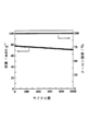
電流密度を100mA/g(1C相当の電流値)としたこと以外は、評価1と同様の条件で1000サイクルの充放電を行い、実施例1のコイン型電池の各サイクルの放電容量および充電容量に対する放電容量の割合(クーロン効率)を求めた。結果を図8に示す。1000サイクル後においても、放電容量は71mAh/gであった。これは、1サイクル目の放電容量(78mAh/g)の91%であり、容量維持率が非常に高いことを示している。また、クーロン効率は、1000サイクルの間、常に99.9%以上の値を示していた。
実施例1のコイン型電池の電流密度5mA/g、500mA/g(5C相当)、1000mA/g(10C相当)、2000mA/g(20C相当)および4000mA/g(40C相当)における90℃での放電容量を測定した。結果を図9に示す。電流密度5mA/gで約90mAh/gの容量、電流密度500mA/gで約80mAh/gの容量、電流密度2000mA/gで約60mAh/gの高い放電容量を示した。
2:正極
2a:正極集電体
2b:正極活物質層
2c:正極リード片
3:負極
3a:負極集電体
3b:負極活物質層
3c:負極リード片
7:ナット
8:鍔部
9:ワッシャ
10:電池ケース
11:電極群
12:容器本体
13:蓋部
14:外部正極端子
15:外部負極端子
16:安全弁
100:溶融塩電池
Claims (5)
- 一般式:An(1-x)M1 nxFe1-yM2 yP2O7(nは、1または2であり、0≦x≦0.5、0≦y≦0.5であり、Aは、アルカリ金属元素であり、M1は、前記元素A以外の元素であり、M2は、Fe以外の元素である)で表される正極活物質を含む正極と、
負極活物質を含む負極と、
前記正極と前記負極との間に介在するセパレータと、
溶融塩電解質と、を含み、
前記溶融塩電解質は、前記元素Aの塩を含むイオン液体を90質量%以上含む、溶融塩電池。 - 前記正極活物質が、Na2-2xM1 2xFe1-yM2 yP2O7(0≦x≦0.1、0≦y≦0.1であり、M1は、ナトリウム以外の元素であり、M2は、Fe以外の元素である)であり、
前記元素Aの塩がナトリウム塩である、請求項1に記載の溶融塩電池。 - 前記正極活物質が、Na2FeP2O7である、請求項2に記載の溶融塩電池。
- 前記イオン液体が、一般式:[(R1SO2)(R2SO2)]N-(R1およびR2は、それぞれ独立に、FまたはCnF2n+1であり、1≦n≦5である)で表わされるアニオンと、カチオンと、の塩を含む、請求項1~請求項3のいずれか1項に記載の溶融塩電池。
- 前記負極活物質が、前記元素Aを含むチタン化合物および難黒鉛化性炭素よりなる群から選択される少なくとも1種である、請求項1~請求項4のいずれか1項に記載の溶融塩電池。
Priority Applications (3)
| Application Number | Priority Date | Filing Date | Title |
|---|---|---|---|
| KR1020167000264A KR20160019491A (ko) | 2013-06-10 | 2014-02-21 | 용융염 전지 |
| US14/895,904 US20160126595A1 (en) | 2013-06-10 | 2014-02-21 | Molten salt battery |
| CN201480033144.5A CN105284000A (zh) | 2013-06-10 | 2014-02-21 | 熔融盐电池 |
Applications Claiming Priority (2)
| Application Number | Priority Date | Filing Date | Title |
|---|---|---|---|
| JP2013121925A JP2014239006A (ja) | 2013-06-10 | 2013-06-10 | 溶融塩電池 |
| JP2013-121925 | 2013-06-10 |
Publications (1)
| Publication Number | Publication Date |
|---|---|
| WO2014199664A1 true WO2014199664A1 (ja) | 2014-12-18 |
Family
ID=52021972
Family Applications (1)
| Application Number | Title | Priority Date | Filing Date |
|---|---|---|---|
| PCT/JP2014/054152 Ceased WO2014199664A1 (ja) | 2013-06-10 | 2014-02-21 | 溶融塩電池 |
Country Status (5)
| Country | Link |
|---|---|
| US (1) | US20160126595A1 (ja) |
| JP (1) | JP2014239006A (ja) |
| KR (1) | KR20160019491A (ja) |
| CN (1) | CN105284000A (ja) |
| WO (1) | WO2014199664A1 (ja) |
Cited By (3)
| Publication number | Priority date | Publication date | Assignee | Title |
|---|---|---|---|---|
| WO2015093208A1 (ja) * | 2013-12-19 | 2015-06-25 | 住友電気工業株式会社 | 溶融塩電池、充放電方法および充放電システム |
| WO2016084573A1 (ja) * | 2014-11-26 | 2016-06-02 | 日本電気硝子株式会社 | 蓄電デバイス用正極材料の製造方法 |
| CN107112146A (zh) * | 2014-12-22 | 2017-08-29 | 日清纺控股株式会社 | 蓄电器件 |
Families Citing this family (5)
| Publication number | Priority date | Publication date | Assignee | Title |
|---|---|---|---|---|
| JP6592891B2 (ja) | 2014-12-22 | 2019-10-23 | 日清紡ホールディングス株式会社 | 二次電池用電解液および二次電池 |
| CN105938904B (zh) * | 2016-05-31 | 2018-09-18 | 中南大学 | 一种钠离子电池用复合正极材料及其制备方法 |
| US10707531B1 (en) | 2016-09-27 | 2020-07-07 | New Dominion Enterprises Inc. | All-inorganic solvents for electrolytes |
| WO2019003904A1 (ja) * | 2017-06-28 | 2019-01-03 | 日本電気硝子株式会社 | ナトリウムイオン二次電池用正極活物質 |
| JP7101005B2 (ja) * | 2018-03-22 | 2022-07-14 | Fdk株式会社 | 正極活物質の製造方法 |
Citations (4)
| Publication number | Priority date | Publication date | Assignee | Title |
|---|---|---|---|---|
| JP2009067644A (ja) * | 2007-09-14 | 2009-04-02 | Kyoto Univ | 溶融塩組成物及びその利用 |
| JP2012186160A (ja) * | 2011-02-18 | 2012-09-27 | Sumitomo Electric Ind Ltd | 電池 |
| WO2013035572A1 (ja) * | 2011-09-05 | 2013-03-14 | 国立大学法人 東京大学 | リチウムもしくはナトリウム含有酸素酸塩化合物の製造方法 |
| JP2013084521A (ja) * | 2011-10-12 | 2013-05-09 | National Institute Of Advanced Industrial & Technology | 耐熱性リチウムイオン二次電池 |
Family Cites Families (8)
| Publication number | Priority date | Publication date | Assignee | Title |
|---|---|---|---|---|
| JP2006196390A (ja) | 2005-01-17 | 2006-07-27 | Tosoh Corp | イオン性液体組成物及びそれを用いた電気化学デバイス |
| JP2011103277A (ja) * | 2009-11-12 | 2011-05-26 | Sumitomo Chemical Co Ltd | ナトリウム二次電池 |
| WO2011135967A1 (ja) * | 2010-04-27 | 2011-11-03 | 住友電気工業株式会社 | 溶融塩電池の電極、溶融塩電池、および電極の製造方法 |
| JP5779050B2 (ja) * | 2010-11-30 | 2015-09-16 | 住友電気工業株式会社 | 溶融塩電池 |
| JP5885199B2 (ja) * | 2011-09-30 | 2016-03-15 | 国立研究開発法人産業技術総合研究所 | リチウム二次電池 |
| WO2013069597A1 (ja) * | 2011-11-10 | 2013-05-16 | 住友電気工業株式会社 | ナトリウム電池用の負極活物質、負極及びナトリウム電池 |
| CN103123981A (zh) * | 2011-11-21 | 2013-05-29 | 中国科学院物理研究所 | 一种钠离子电池用非水电解质、钠离子电池及用途 |
| CN105027331A (zh) * | 2013-02-04 | 2015-11-04 | 住友电气工业株式会社 | 钠熔盐电池用电极和钠熔盐电池 |
-
2013
- 2013-06-10 JP JP2013121925A patent/JP2014239006A/ja active Pending
-
2014
- 2014-02-21 CN CN201480033144.5A patent/CN105284000A/zh active Pending
- 2014-02-21 WO PCT/JP2014/054152 patent/WO2014199664A1/ja not_active Ceased
- 2014-02-21 US US14/895,904 patent/US20160126595A1/en not_active Abandoned
- 2014-02-21 KR KR1020167000264A patent/KR20160019491A/ko not_active Ceased
Patent Citations (4)
| Publication number | Priority date | Publication date | Assignee | Title |
|---|---|---|---|---|
| JP2009067644A (ja) * | 2007-09-14 | 2009-04-02 | Kyoto Univ | 溶融塩組成物及びその利用 |
| JP2012186160A (ja) * | 2011-02-18 | 2012-09-27 | Sumitomo Electric Ind Ltd | 電池 |
| WO2013035572A1 (ja) * | 2011-09-05 | 2013-03-14 | 国立大学法人 東京大学 | リチウムもしくはナトリウム含有酸素酸塩化合物の製造方法 |
| JP2013084521A (ja) * | 2011-10-12 | 2013-05-09 | National Institute Of Advanced Industrial & Technology | 耐熱性リチウムイオン二次電池 |
Non-Patent Citations (3)
| Title |
|---|
| ATSUSHI WATARAI ET AL.: "A rechargeable lithium metal battery operating at intermediate temperatures using molten alkali bis (trifluoromethylsulfonyl)amide mixture as an electrolyte", JOURNAL OF POWER SOURCES, vol. 183, 27 May 2008 (2008-05-27), pages 724 - 729 * |
| CHIH-YAO CHEN ET AL.: "Pyrophosphate Na2FeP2O7 as a low-cost and high-performance positive electrode material for sodium secondary batteries utilizing an inorganic ionic liquid", JOURNAL OF POWER SOURCES, vol. 246, 17 August 2013 (2013-08-17), pages 783 - 787, XP028739939, DOI: doi:10.1016/j.jpowsour.2013.08.027 * |
| PRABEER BARPANDA ET AL.: "Sodium iron pyrophosphate: A novel 3.0 V iron-based cathode for sodium-ion batteries", ELECTROCHEMISTRY COMMUNICATIONS, vol. 24, pages 116 - 119, XP028515949, DOI: doi:10.1016/j.elecom.2012.08.028 * |
Cited By (4)
| Publication number | Priority date | Publication date | Assignee | Title |
|---|---|---|---|---|
| WO2015093208A1 (ja) * | 2013-12-19 | 2015-06-25 | 住友電気工業株式会社 | 溶融塩電池、充放電方法および充放電システム |
| WO2016084573A1 (ja) * | 2014-11-26 | 2016-06-02 | 日本電気硝子株式会社 | 蓄電デバイス用正極材料の製造方法 |
| US10763506B2 (en) | 2014-11-26 | 2020-09-01 | Nippon Electric Glass Co., Ltd. | Method of manufacturing positive electrode material for electrical storage device |
| CN107112146A (zh) * | 2014-12-22 | 2017-08-29 | 日清纺控股株式会社 | 蓄电器件 |
Also Published As
| Publication number | Publication date |
|---|---|
| JP2014239006A (ja) | 2014-12-18 |
| KR20160019491A (ko) | 2016-02-19 |
| US20160126595A1 (en) | 2016-05-05 |
| CN105284000A (zh) | 2016-01-27 |
Similar Documents
| Publication | Publication Date | Title |
|---|---|---|
| WO2014199664A1 (ja) | 溶融塩電池 | |
| CN115939504A (zh) | 用于固态电池组的凝胶电解质体系 | |
| JP6507642B2 (ja) | ナトリウム溶融塩電池用電極およびナトリウム溶融塩電池 | |
| US20170025865A1 (en) | Molten-salt battery, charge-discharge method, and charge-discharge system | |
| JP2015037024A (ja) | リチウムイオン二次電池、充放電システムおよび充放電方法 | |
| JP6592380B2 (ja) | ナトリウムイオン二次電池用電解質およびナトリウムイオン二次電池 | |
| WO2016056495A1 (ja) | ナトリウムイオン二次電池用電解液およびナトリウムイオン二次電池 | |
| WO2014171196A1 (ja) | 溶融塩電解質及びナトリウム溶融塩電池 | |
| JP6064825B2 (ja) | ナトリウム溶融塩電池 | |
| WO2014136357A1 (ja) | ナトリウム溶融塩電池用正極活物質、ナトリウム溶融塩電池用正極およびナトリウム溶融塩電池 | |
| JP6252220B2 (ja) | ナトリウムイオン二次電池、充放電方法および充放電システム | |
| WO2014181571A1 (ja) | ナトリウム溶融塩電池およびこれに用いる溶融塩電解質またはイオン性液体 | |
| JP6349998B2 (ja) | ナトリウムイオン二次電池 | |
| JP6194633B2 (ja) | ナトリウム溶融塩電池 | |
| JP2018156724A (ja) | リチウムイオン二次電池 | |
| JP2016038945A (ja) | 溶融塩電解質および溶融塩電池 | |
| JP2015118846A (ja) | 溶融塩電池およびその充放電方法 | |
| JP2014235912A (ja) | ナトリウム溶融塩電池およびその製造方法 | |
| JP2015041433A (ja) | ナトリウム溶融塩電池 | |
| JP2020004598A (ja) | 電池 | |
| JP2016076463A (ja) | 非水電解質、ナトリウムイオン二次電池、充放電方法および充放電システム | |
| JP2016038946A (ja) | 溶融塩電池およびその製造方法 | |
| JP2015046342A (ja) | 溶融塩電池の製造方法および溶融塩電池 | |
| JP2015022907A (ja) | ナトリウム溶融塩電池 | |
| JP2019125538A (ja) | 負極、半二次電池、二次電池 |
Legal Events
| Date | Code | Title | Description |
|---|---|---|---|
| WWE | Wipo information: entry into national phase |
Ref document number: 201480033144.5 Country of ref document: CN |
|
| 121 | Ep: the epo has been informed by wipo that ep was designated in this application |
Ref document number: 14811230 Country of ref document: EP Kind code of ref document: A1 |
|
| WWE | Wipo information: entry into national phase |
Ref document number: 14895904 Country of ref document: US |
|
| NENP | Non-entry into the national phase |
Ref country code: DE |
|
| ENP | Entry into the national phase |
Ref document number: 20167000264 Country of ref document: KR Kind code of ref document: A |
|
| 122 | Ep: pct application non-entry in european phase |
Ref document number: 14811230 Country of ref document: EP Kind code of ref document: A1 |