WO2014196609A1 - Corps de boîtier isolant et réfrigérateur - Google Patents
Corps de boîtier isolant et réfrigérateur Download PDFInfo
- Publication number
- WO2014196609A1 WO2014196609A1 PCT/JP2014/065001 JP2014065001W WO2014196609A1 WO 2014196609 A1 WO2014196609 A1 WO 2014196609A1 JP 2014065001 W JP2014065001 W JP 2014065001W WO 2014196609 A1 WO2014196609 A1 WO 2014196609A1
- Authority
- WO
- WIPO (PCT)
- Prior art keywords
- heat insulating
- insulating material
- box
- vacuum heat
- refrigerator
- Prior art date
Links
Images


Classifications
-
- F—MECHANICAL ENGINEERING; LIGHTING; HEATING; WEAPONS; BLASTING
- F25—REFRIGERATION OR COOLING; COMBINED HEATING AND REFRIGERATION SYSTEMS; HEAT PUMP SYSTEMS; MANUFACTURE OR STORAGE OF ICE; LIQUEFACTION SOLIDIFICATION OF GASES
- F25D—REFRIGERATORS; COLD ROOMS; ICE-BOXES; COOLING OR FREEZING APPARATUS NOT OTHERWISE PROVIDED FOR
- F25D23/00—General constructional features
- F25D23/06—Walls
- F25D23/062—Walls defining a cabinet
-
- F—MECHANICAL ENGINEERING; LIGHTING; HEATING; WEAPONS; BLASTING
- F25—REFRIGERATION OR COOLING; COMBINED HEATING AND REFRIGERATION SYSTEMS; HEAT PUMP SYSTEMS; MANUFACTURE OR STORAGE OF ICE; LIQUEFACTION SOLIDIFICATION OF GASES
- F25D—REFRIGERATORS; COLD ROOMS; ICE-BOXES; COOLING OR FREEZING APPARATUS NOT OTHERWISE PROVIDED FOR
- F25D2201/00—Insulation
- F25D2201/10—Insulation with respect to heat
- F25D2201/14—Insulation with respect to heat using subatmospheric pressure
Definitions
- the present invention relates to a heat insulating box with a vacuum heat insulating material, a refrigerator with a vacuum heat insulating material, a showcase, a hot water storage device, a device with a vacuum heat insulating material, and the like.
- a technology has been proposed in which a vacuum heat insulating material is arranged in addition to a hard urethane foam in a heat insulating box body in which an outer box and an inner box are formed. And a vacuum heat insulating material, and an invention of a heat insulating box body in which the coverage of the vacuum heat insulating material is defined with respect to the outer box surface area has been proposed (see Patent Document 1).
- a rail member that supports a drawer-type case is fixed to an inner box with a screw or the like (see Patent Document 3).
- the rail member is fixed to the drawer door of the drawer-type storage chamber with a screw or the like. (See Patent Document 4)
- the vacuum heat insulating material has a heat insulating performance of, for example, 6 times or more that of a conventional hard urethane foam. For this reason, from the viewpoint of energy saving and the like, in addition to the hard urethane foam, a vacuum heat insulating material has also been disposed in the space formed between the outer box and the inner box. In recent years, as the demand for energy saving increases, the amount of vacuum heat insulating material disposed in the heat insulating box, such as the heat insulating box described in Patent Document 1, has also increased.
- the conventional heat insulation box has been manufactured based on the technical idea that the hard urethane foam mainly has a heat insulation function, and the vacuum heat insulation material assists the heat insulation function of the hard urethane foam.
- the conventional heat insulation box body is obtained by filling the space between the inner box and the outer box with rigid urethane foam at a predetermined density, but the strength of the box body is reduced.
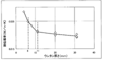
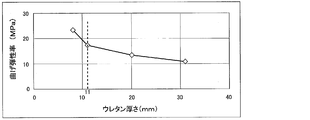
- the thickness of the urethane decreases, the density of the urethane increases and the heat insulation performance decreases, so that the heat insulation performance is satisfied and the necessary box strength is obtained. It was difficult.
- the heat insulation performance of the wall surface and box body and the strength of the box body and wall are secured by rigid urethane foam, and the wall thickness of the heat insulation box body If the thickness of the rigid urethane foam is reduced in order to reduce the thickness, the heat insulation performance of the heat insulation box is insufficient or the strength is insufficient, and it is difficult to reduce the wall thickness.
- the heat insulation box of patent document 1 since the usage-amount (coverage rate) of a vacuum heat insulating material is increased, the bending elastic modulus (rigidity of a hard urethane foam) of hard urethane foam is enlarged. It seems that the wall thickness can be reduced to some extent from the strength aspect of the heat insulation box.
- the heat insulation box described in Patent Document 1 is manufactured based on the technical idea that the hard urethane foam is mainly responsible for the heat insulation function, and the vacuum heat insulating material assists the heat insulation function of the hard urethane foam.
- the foam mainly performs a heat insulating function, and the vacuum heat insulating material assists the heat insulating function of the hard urethane foam, and the heat insulating performance of the heat insulating box and the strength of the wall surface are ensured by the hard urethane foam.
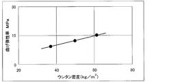
- the bending elastic modulus and density of the rigid urethane foam are set to be equal to or less than predetermined values (flexural modulus of 10 MPa or less, density of 60 kg / m 3 or less). ing.
- Patent Document 2 discloses that as a measure against the strength of a heat insulating box provided with a vacuum heat insulating material, a plastic material or the like is formed on the outer packaging material of the vacuum heat insulating material into a desired shape by vacuum forming, pressure forming, etc.
- a vacuum heat insulating material, an inner box, and an outer box formed into a concavo-convex shape ensuring strength by filling a core material is used.
- the inner box and the outer box are fitted with a concave and convex shape that is substantially the same as the concave and convex shape of the outer packaging material of the vacuum heat insulating material to give strength to the inner box and the outer box.
- the vacuum heat insulating material also needs to be molded into an irregular shape to ensure strength
- the core material enclosed in the outer packaging material also needs to have a shape that conforms to the irregular shape of the outer packaging material. It is necessary to use a granular material having the property, and the cost is increased as compared with a fiber-based core material such as glass fiber, and the heat insulation performance may be deteriorated. Further, the back surface of the room (the storage space for stored items in the heat insulation box) has an uneven shape, the shape is complicated, and the design is poor.
- the urethane inlet provided in the width direction end portion (or the vertical end portion) of the back surface of the heat insulating box is a vacuum heat insulating material. Therefore, the vacuum heat insulating material cannot be increased in the width direction (or the vertical direction), and it is difficult to improve the heat insulating performance.
- a rail member or a door frame that supports a case of a drawer-type storage chamber is insulated with a heat insulating wall (an inner box, or an urethane box between an inner box and an outer box). Material, or a reinforcing member provided between the inner box and the outer box).
- a vacuum heat insulating material is disposed between the outer box and the inner box, if the thickness of the heat insulating material between the vacuum heat insulating material and the inner box is thin, the thickness of the vacuum heat insulating material may vary. There is a risk that the fixing screw of the rail member or the door frame may damage or break the outer packaging material of the vacuum heat insulating material, thereby reducing the heat insulating performance and reliability of the vacuum heat insulating material.
- the length of the screw portion of the screw could not be shortened to a predetermined length or less.
- another member that is held or fixed to a heat insulating wall having a vacuum heat insulating material by a screw or a fitting structure for example, a heavy weight support member that supports a heavy object such as a rail member or a door frame that supports a case, or
- a vibration-affected member that is affected by vibration during operation such as a cooler that generates cool air to cool the storage room or a fan that blows cool air into the storage room
- the attachment site has sufficient mounting strength.
- the wall thickness of the fixing member such as a screw is difficult to reduce to a predetermined length (for example, 15 mm) or less because of the mounting strength of the screw. It was difficult to increase the internal volume.
- the present invention has been made to solve the above-mentioned problems, and has as its main purpose to ensure the heat insulation performance and strength of the heat insulation box.
- an object is to obtain a heat insulating box, a refrigerator, a hot water storage device, a device having a high temperature part or a low temperature part, etc., capable of reducing the thickness of the heat insulating wall or the heat insulating material.
- the purpose is to obtain a heat insulating box, refrigerator, hot water storage device, equipment, etc.
- the heat insulating wall or the heat insulating material is made thinner.
- the purpose is to obtain a heat insulating box, refrigerator, hot water storage device, equipment, etc.
- Another object of the present invention is to obtain a heat-insulating box, a refrigerator, a hot water storage device, equipment, and the like that are highly reliable and have a large internal volume.
- the thickness of the heat insulation wall is reduced, and the size of the outer shape of the heat insulation box such as a cylinder, a square tube, or a box having a front opening (for example, the outer diameter)
- the purpose is to obtain a compact heat insulating box, refrigerator, hot water storage device, equipment, etc. with reduced width, depth, height, etc.
- the refrigerator of the present invention is formed of an outer box and an inner box, and a box having a back wall and a side wall;
- a storage chamber having an opening on the front surface formed by partitioning the box body with a partition wall;
- a drawer-type case that is housed in the storage chamber and pulled out via a rail member provided on the side wall of the storage chamber;
- a vacuum insulating material disposed between the inner box and the outer box, the core material being formed of a fiber-based material made of inorganic fiber or organic fiber, and forming the side wall provided with the rail member;
- the refrigerator of the present invention is formed of an outer box and an inner box, and has a top wall, a back wall, a side wall, and a box body having a bottom wall, A storage chamber having an opening on the front surface formed by partitioning the box body with a partition wall; A drawer-type case that is housed in the storage chamber and pulled out via a rail member provided on the partition wall that forms the bottom or top surface of the storage chamber; A vacuum heat insulating material disposed in the partition wall in which the core material is formed of a fiber-based material made of inorganic fiber or organic fiber, and the rail member is provided; In the partition wall at a position facing the rail member, a heat insulating material that is filled, applied, or arranged between the outer member forming the partition wall and the vacuum heat insulating material, With The thickness of the heat insulating material at a position facing the rail member is smaller than 10 mm, and the density of the heat insulating material is larger than 60 kg / m 3 .
- the heat insulation box of the present invention is formed of an outer box and an inner box, and is a box having a back wall and a side wall, provided in the box, and having a storage chamber having an opening on the front surface,
- a vacuum heat insulating material provided on the outer box side in the back wall; Provided at the width direction end or the vertical direction end of the back wall, and an injection port for injecting a stock solution of foam heat insulating material into the back wall, and
- the vacuum heat insulating material is provided with a notch such as a notch or an opening so as not to interfere with the inlet at a portion facing the inlet.
- the thickness of the foam heat insulating material after injection is smaller than 10 mm.
- the heat insulating box having the above configuration is applied to a device such as a refrigerator, so that the wall thickness of the box can be reduced, so that the volume of the storage space or the storage chamber can be increased without increasing the outer shape of the box. Can be increased.
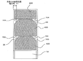
- FIG. 1 It is a schematic diagram of another cross-sectional shape of the heat insulation box side wall after a hard urethane foam foams. It is principal part sectional drawing of the rail attachment part vicinity of the refrigerator showing embodiment of this invention. It is principal part sectional drawing of the rail attachment part vicinity of another refrigerator showing embodiment of this invention. It is principal part sectional drawing of the rail attachment part vicinity of another refrigerator showing embodiment of this invention. It is principal part sectional drawing of the rail attachment part vicinity of another refrigerator showing embodiment of this invention.
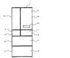
- Embodiment 1 (refrigerator) 1 is a front view of a refrigerator representing Embodiment 1 of the present invention
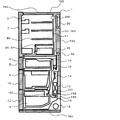
- FIG. 2 is a side sectional view of the refrigerator illustrating Embodiment 1 of the present invention
- the refrigerator 1 includes a refrigerator compartment 2 which is a double door (or openable) storage room at the top.
- an ice making room 3 and a switching room 4 which are storage rooms are arranged in parallel on the left and right.
- a freezer room 6 serving as a storage room is provided at the bottom of the refrigerator 1
- a vegetable room 5 serving as a storage room is provided above the freezer room 6.
- the vegetable compartment 5 is provided above the freezing compartment 6 below the ice making compartment 3 and the switching compartment 4 arranged in parallel on the left and right.
- the refrigerator compartment 2 which is a storage room, has a storage product storage space for storing storage products (food, beverages, etc.), and the storage product storage space has a plurality of resins on which the storage products are placed.
- a shelf 80 made of glass or glass is provided below this storage space (under the shelf in the cabinet), containers 2X and 2Y having a substantially sealed structure are provided, and a chilled chamber 2X controlled to a chilled temperature range of about + 3 ° C to -3 ° C, Alternatively, it is used as a vegetable room 2Y controlled in a temperature range of the vegetable room maintained at about + 3 ° C. to + 5 ° C.
- the substantially sealed containers 2X and 2Y may be used as an egg compartment for storing eggs. Further, the containers 2X and 2Y having a substantially sealed structure have, for example, a pull-out structure, and a stored product can be taken in and out by pulling out the container.
- a container having a substantially sealed structure can be configured by providing a detachable lid on the upper surface opening of the container having an upper surface opening having an upper surface.
- the lid may be provided on the container, may be provided on a shelf 80 or a partition wall provided on the top of the container, or the shelf or the partition wall itself on the top of the container may be used as the lid.
- the arrangement of the respective chambers is not limited to the present embodiment, and the ice making chamber 3 and the switching chamber 4 are arranged in parallel on the left and right below the refrigerating chamber 2 provided in the upper stage.
- An ice making room arranged in parallel with the so-called vegetable room 5 in the freezing room 6 below the arranged ice making room 3 and switching room 4 and above the vegetable room 5 provided in the lower stage.
- the mid freezer type in which the freezing chamber 6 is disposed is closer to the low temperature chamber (for example, the ice making chamber 3, the switching chamber 4, the freezing chamber 6), so that a heat insulating material between the low temperature chambers is provided. Since it is unnecessary and there are few heat leaks, an energy-saving and low-cost refrigerator can be provided.
- the front side opening of the refrigerating room 2 which is a storage room is provided with a double door type refrigerating room door 7 which can be freely opened and closed.
- This refrigerating room door 7 has a refrigerating room door left 7A and a refrigerating room door 7A.
- Two doors on the right side of the room door 7B constitute a Kannon type door.
- a single-piece rotary door may be used instead of the Kannon door.
- the ice making room 3, the switching room 4, the vegetable room 5, and the freezing room 6, which are other storage rooms have a drawer type ice making room door 8 and a switching room that can freely open and close the opening of the ice making room 3.
- a drawer-type freezer compartment door 11 that can freely open and close the opening is provided.
- a rail member is attached to the inner box 750 forming the storage room, such as a screw.
- the door and door frame are fixed or held by the rail fixing member 735 or the fitting structure, and the door frame fixed or held on the door inner plate slides on the rail member directly or via a roller. The case placed on can be pulled out.
- an operation switch (room for setting the temperature in the storage chamber) is provided on either the left or right refrigerator door left 7A or the right refrigerator door right 7B of the refrigerator room 2 as a storage room.
- a selection switch 60a, a temperature zone changeover switch 60b, a quick freeze switch 60c, an ice making changeover switch 60d, a mist supply switch 60e) and an operation panel 60 for displaying temperature information such as the inside temperature and the set temperature are provided.
- Operation information of the switch, display information on the liquid crystal display unit, temperature information in the storage chamber, and the like are controlled by the control device 30 configured by a control board mounted with a microcomputer or the like provided on the upper back of the refrigerator (the back of the refrigerator compartment). .
- a compressor 12 is disposed in the machine room 1A provided at the lowermost back of the refrigerator 1.
- the refrigerator 1 is provided with a refrigeration cycle, and the compressor 12 is a component that constitutes the refrigeration cycle and is disposed in the machine room 1A, and has an action of compressing a refrigerant in the refrigeration cycle.
- the refrigerant compressed by the compressor 12 is condensed in a condenser (not shown).
- the condensed refrigerant is decompressed in a capillary tube (not shown) or an expansion valve (not shown) which is a decompression device.
- the cooler 13 is a component that constitutes the refrigeration cycle of the refrigerator and is disposed in the cooler chamber 131.
- the refrigerant decompressed by the decompression device evaporates in the cooler 13, and the gas around the cooler 13 is cooled by the endothermic action during the evaporation.
- the cool air circulation fan 14 is disposed in the cooler chamber 131 in the vicinity of the cooler 13, and cools the cool air around the cooler 13 as a cool air path (for example, the switching chamber cool air path 16 or the refrigerating room cool air wind). It is for ventilating to each room (refrigeration room 2, ice making room 3, switching room 4, vegetable room 5, freezing room 6) which is a storage room of refrigerator 1 via way 50 etc.).
- a defrosting heater 150 (a defrosting glass tube heater, which is a defrosting means for defrosting the cooler 13, for example, in a quartz glass tube. And a carbon heater using carbon fibers that emit light having a wavelength of 0.2 ⁇ m to 4 ⁇ m that is transmitted through the quartz glass tube.
- a heater roof 151 is provided above the defrosting heater 150 between the cooler 13 and the defrosting heater 150 so that the defrosting water falling from the cooler 13 does not directly hit the defrosting heater 150. ing.
- the frost in the cooler 13 can be efficiently melted by radiant heat transfer, so the surface temperature is low (about 70 ° C to 80 ° C). If a flammable refrigerant (such as isobutane, which is a hydrocarbon refrigerant) is used as the refrigerant used in the refrigeration cycle, the risk of ignition is reduced even if refrigerant leakage occurs. it can. Moreover, since the frost of the cooler 13 can be efficiently melted by radiant heat transfer as compared with the nichrome wire heater, the frost formed on the cooler 13 gradually melts, and the frost quickly falls into a lump. Therefore, since the falling sound when falling on the heater roof 151 can be reduced, a refrigerator with low noise and good defrosting efficiency can be provided.
- a black medium heater such as a carbon heater
- the defrosting heater 150 may be a stowage type heater integrally incorporated in the cooler 13.
- a glass tube type heater and a bite type heater may be used in combination.
- the defrost water generated in the cooler 13 or the defrost water dropped on the heater roof 151 falls in the cooler chamber and is provided outside the refrigerator (for example, a machine) from the defrost water discharge port provided below the cooler chamber 131. It is discharged to an evaporating dish or the like provided in the chamber 1A.
- the switching chamber damper 15 that is an air volume adjusting means adjusts the amount of cool air blown to the switching chamber 4 that is a storage chamber by the cool air circulation fan 14, and controls the temperature in the switching chamber 4 to a predetermined temperature, This is for switching the set temperature of the switching chamber 4.
- the cold air cooled by the cooler 13 is blown into the switching chamber 4 through the switching chamber cold air passage 16 which is a cold air passage.
- the switching chamber cold air passage 16 is arranged downstream of the switching chamber damper 15.
- the cold room damper 55 as the air volume adjusting means also adjusts the amount of cold air blown to the cold room 2 as the storage room by the cold air circulation fan 14 and controls the temperature in the cold room 2 to a predetermined temperature. Or for changing the set temperature of the refrigerator compartment 2.
- the cold air cooled by the cooler 13 is blown into the refrigerating chamber 2 through the refrigerating chamber cold air passage 50 which is a cold air passage.
- the switching room 4 which is a storage room, is a room (storage) in which the temperature in the storage room can be selected from a plurality of stages between a freezing temperature zone ( ⁇ 17 ° C. or lower) and a vegetable room temperature zone (3 to 10 ° C.).
- the temperature in the storage room is selected or switched by operating the operation panel 60 installed in either the refrigerator compartment door left 7A or the refrigerator compartment door right 7B of the refrigerator 1.
- a switching chamber thermistor 19 (see FIG. 3), which is a first temperature detecting means for detecting the air temperature in the switching chamber 4, is installed on, for example, the back wall surface of the switching chamber 4.
- a thermopile which is a second temperature detecting means for directly detecting the surface temperature of the stored material put into the switching chamber 4 which is a storage chamber, on the top surface (center portion, front surface portion, rear surface portion, etc.) 22 (see FIG. 3 or an infrared sensor) is installed.
- the air passage that sends the cold air from the cooler chamber 131 to the switching chamber 4 is provided with a switching chamber damper 15 that is an air volume adjusting device that can block the air flow by controlling the air volume and blocking the air passage.
- the temperature of the switching chamber 4 is adjusted to be in the selected temperature range by opening and closing the switching chamber damper 15 by the detection temperature of the switching chamber thermistor 19 (or the detection temperature of the thermopile 22) as the temperature detection means. Or controlled by the control device 30 so as to fall within the set temperature range. Further, the thermopile 22 serving as the second temperature detecting means directly detects the temperature of the food that is stored in the switching chamber 4.
- the machine room 1A is provided at the lowermost part of the back surface of the refrigerator 1 is shown, it may be provided at the upper part of the back surface (for example, the uppermost part of the back surface).
- Electrostatic atomization which is a mist device that supplies mist to be sterilized or humidified in the storage chamber, for example, to the partition wall 51 (back wall, heat insulating wall) on the back side (back side) of the refrigerator compartment 2, for example.
- An apparatus 200 is provided.
- a cooling member for example, a cooling plate
- the rear partition wall 51 or the cooler chamber wall that forms the front wall of the cooler chamber 131 in which the cooler 13, the cool air circulation fan 14, and the like are arranged is provided so as to contact or penetrate.
- the partition wall 51 may be the back wall 730, the side wall 790, the top wall 740, the bottom wall 780, and the partition wall 24 between the storage rooms.
- This cooling member (for example, a cooling plate) is stored in the cold air in the cold air flow paths 50 and 760, which are cold air paths provided on the back side, the side surface, and the top and bottom of the partition wall 51, or stored in the partition wall 51.
- a low-temperature storage room for example, a freezing room, ice making room, switching room, etc. that is cooler than the storage room
- a low-temperature storage room for example, a freezing room, ice making room, switching room, etc. that is cooler than the storage room
- the electrostatic atomizer 200 will be described here, another sterilizer, sterilizer, humidifier, or the like may be used as long as it can be sterilized, sterilized, or humidified in the storage chamber.
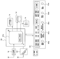
- FIG. 3 is a block diagram of the control device 30 of the refrigerator 1 representing the first embodiment of the present invention.
- the control device 30 is equipped with a microcomputer 30a (microcomputer) and controls the temperature of each storage chamber of the refrigerator 1, the rotational speed control of the compressor 12 and the cool air circulation fan 14, and the switching chamber damper according to a program stored in advance. 15. Opening / closing control of the refrigerator compartment damper 55, voltage application control to the mist device (electrostatic atomizer) 200, and the like are performed.
- the operation panel 60 includes, for example, the switches shown below.
- a room selection switch 60a for selecting a storage room such as a refrigerator room, a freezer room, a switching room
- a temperature zone changeover switch 60b for changing the temperature zone (refrigeration, freezing, chilled, soft freezing, etc.) of a storage room such as a changeover room or switching between rapid cooling, strong / medium / weak, etc .
- Instantaneous freezing switch 60c that freezes and stores the storage chamber through a supercooled state (flash freezing is also called supercooled freezing);
- ice making, ice making changeover switch 60d for selecting transparent ice, normal, rapid, stop, etc .
- a mist supply switch 60e electrostatic spray selection
- mist device 200 for energizing the mist device 200 to supply mist (electrostatic spray) into the storage chamber.
- a temperature detection sensor for detecting the temperature in the storage room for example, the switching room 4
- the switching chamber thermistor 19 as the first temperature detection means and the thermopile 22 as the second temperature detection means.
- the detected temperature of the switching chamber thermistor 19 which is the first temperature detecting means for detecting the temperature of the air in the storage chamber (for example, the switching chamber 4) is input to the microcomputer 30a constituting the control device 30, and the microcomputer 30a (for example, In the microcomputer 30a, temperature determination is performed by comparing with a predetermined value, and control is performed so that the temperature falls within a predetermined temperature range.
- thermopile 22 which is a second temperature detecting means for directly detecting the surface temperature of food in the storage room (for example, the switching room 4) is input to the microcomputer 30a, and the microcomputer 30a (for example, in the microcomputer 30a) And calculating the surface temperature of the food or the like, and then performing predetermined temperature control such as quick freezing control or supercooling freezing control.
- the control device 30 performs various controls such as temperature control in each storage room (refrigeration room 2, ice making room 3, switching room 4, vegetable room 5, freezing room 6) and energization control of the electrostatic atomizer 200.
- the set temperature, food (surface) temperature of each storage room, and each storage room are installed on the operation panel 60 (display panel) or server or portable terminal provided on either the left of the refrigerator door 7A or the right of the refrigerator door 7B.
- the operation status of the electrostatic atomizer 200 is displayed.
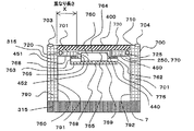
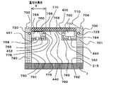
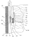
- FIG. 4 is a cross-sectional view of the refrigerator representing the first embodiment of the present invention.
- the figure is a cross-sectional view of the refrigerator 1 cut along a plane perpendicular to the vertical direction of the refrigerator 1. 4, parts that are the same as those in FIGS. 1 to 3 are given the same reference numerals, and descriptions thereof are omitted.
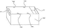
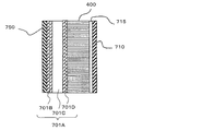
- a heat insulating box 700 constituting the refrigerator 1 is composed of an outer box 710 and an inner box 750, and a vacuum heat insulating material 400 is disposed between the outer box 710 and the inner box 750.
- the vacuum heat insulating material 400 is provided on the back surface of the refrigerator 1 and is directly attached to the outer box 710 via a second adhesive which is a second interposed member such as hot melt or double-sided tape.
- the vacuum heat insulating material 400 is directly attached to a part of the inner box 750 (for example, a substantially central portion in the left-right direction of the wall surface forming the back of the inner box 750) with an adhesive,
- the left and right end portions (corner portions) in the vicinity of the side wall 790 excluding the central portion are formed with convex portions 450 that protrude to the front side from the rear wall 730, and the vacuum heat insulating material 400 is only a predetermined length from the convex portion 450.
- an adhesive that is a first interposed member (for example, a foam heat insulating material having self-adhesive properties such as hard urethane may be used) is filled between the inner box 750 and the vacuum heat insulating material 400,
- the vacuum heat insulating material 400 is provided between the inner box 750 and the outer box 710 via an adhesive (for example, hard urethane) that is a first interposed member. Therefore, the vacuum heat insulating material 400 is bonded, fixed, or fixed to the inner box 750 or the outer box 710 by the first and second interposed members.
- the back shape of the inner box 750 is formed as a concave groove-shaped concave portion 440 (also referred to as a first concave portion) having a substantially central portion extending vertically.
- the vacuum heat insulating material 400 is directly attached to the outer box 710 and the inner box 750 via an adhesive.
- the rear shape of the inner box 750 is such that the width direction (left and right direction) end side is the front opening side compared to the width direction (left and right direction) substantially central portion.
- the back surface shape of the inner box 750 has a concave portion 440 that has a concave groove shape with a substantially central portion in the left-right direction recessed toward the outer box side (rear side of the refrigerator) as compared to the left and right end portions.
- 440 is provided in the vertical direction of the refrigerator in the storage room (for example, the refrigerator compartment 2). That is, the concave portion 440 is formed by the side surface 452 of the convex portion 450 and the rear wall 730, and the inner box 750 that forms the inner surface (storage chamber side) of the rear wall 730 and the outer box 710 that forms the outer surface of the rear wall 730.
- a plate-like vacuum heat insulating material 400 is provided between the two.
- a plate-like vacuum heat insulating material 400 is also provided between the inner box 750 that forms the inner surface (the storage chamber side) of the side wall 790 and the outer box 710 that forms the outer surface of the side wall 790. May be.
- the cold air passage 760 provided in the back wall 730 or the recess 440 is provided on the first air passage component 762 that is a cover member having design properties, and on the back side (inner box 750 side) of the first air passage component 762,
- the second air passage component 764 having heat insulation properties is disposed in the recess 440.
- the first air path component 762 or the second air path component 764 as the cover member has an attachment portion (engagement portion), and the attachment portion (engagement) provided on the convex portion 450 or the back wall 730.
- the cover member 760 is attached to the convex portion 450 or the back wall 730 by fitting into the portion) or engaging the attachment portions with a fixing member such as a screw.
- the vacuum heat insulating material 400 is disposed between the outer box 710 and the inner box 750 on the center side in the width direction (the range of the overlap length X).
- the space between the vacuum heat insulating material 400 and the inner box 750 is filled with an adhesive (self-adhesive foam heat insulating material 701, for example, hard urethane) as a first interposed member.
- an adhesive self-adhesive foam heat insulating material 701, for example, hard urethane
- the heat insulating material 701 for example, hard urethane
- the heat insulation performance and the box strength may be improved by enlarging the vacuum heat insulating material 400 in the width direction and increasing the arrangement area of the vacuum heat insulating material 400 in the width direction, but the cost increases. Therefore, if the heat insulation performance and strength are equal to or higher than the predetermined values, a portion where the vacuum heat insulating material 400 is not provided may be set.
- the vacuum heat insulating material 400 is directly attached to the outer box 710 via a second adhesive which is a second interposed member, and the inner box 750 is the first interposed member. It is pasted via an adhesive having self-adhesive properties and foaming properties such as urethane. (For example, a hard urethane foam as an adhesive is filled between the vacuum heat insulating material 400 and the inner box 750.)
- heat insulation mainly for heat insulation such as urethane in a portion where the vacuum heat insulating material is disposed in the width direction of the rear surface of the storage room as in the past (for example, Patent Document 2).
- heat insulation such as urethane is provided in the vertical direction on the left and right end sides (width direction end portions side). Since the convex portion 450 composed of the material 701 is formed, the torsional strength and the bending strength of the box body are improved by forming the convex portion 450.
- the convex portion 450 is provided so as to at least partially overlap the arrangement portion of the vacuum heat insulating material 400 in the width direction of the rear surface of the storage chamber (so as to overlap by the overlap length X).
- the rigid urethane foam filled in the convex portion 450 is also applied to a part between the vacuum heat insulating material 400 and the inner box 750 on the end side in the width direction (left-right direction) of the vacuum heat insulating material 400.
- the thickness of the rigid urethane foam filled between the vacuum heat insulating material 400 at the position facing the convex portion 450 and the inner box 750 is set to the vacuum heat insulating material 400 at the position facing the concave portion 440, Since the thickness of the hard urethane foam filled in the inner box 750 can be made larger, the adhesion area of the hard urethane foam to the vacuum heat insulating material 400 can be increased, and the hard foam of the vacuum heat insulating material 400 portion can be increased. Because it can increase the thickness of the tongue forms the bonding strength between the rigid urethane foam and vacuum insulation material 400 in the convex portion 450 is increased.
- the strength of the box body can be greatly improved.
- the convex part 450 since the thickness of a hard urethane foam can be enlarged, even if there exists a part in which the vacuum heat insulating material 400 is not provided, heat insulation performance improves.
- the vacuum heat insulating material, the inner box, and the outer box into a complicated shape in order to ensure the box strength as in the conventional patent document 2, and the vacuum heat insulating material.
- Organic and inorganic fiber core materials such as cotton-like core materials and non-woven core materials
- Refrigerators, showcases, water heaters, devices equipped with vacuum heat insulating materials, and the like can be obtained.
- the back of the box is deformed to form irregularities in the storage chamber, or the storage box door (for example, refrigerated) provided on the front of the storage chamber (for example, the refrigeration chamber 2) is deformed, for example.
- the chamber door 7) is not tilted, and one of the left and right doors (7A, 7B) is not tilted to cause misalignment, so that the storage chamber door can be opened and closed smoothly.
- the appearance (designability) is good.
- the opening and closing doors provided on the inner wall of the storage room for example, the ice making room 3, the switching room 4, the vegetable room 5, the freezing room 6 and the like
- the left and right side walls and the rail member for the drawer case are provided. Since the installation height does not differ from side to side and does not tilt, the case can be inserted and removed smoothly, and a highly reliable and easy-to-use refrigerator and equipment can be obtained.
- the vacuum heat insulating material 400 when the vacuum heat insulating material 400 is flat, in the state where the vacuum heat insulating material 400 is mounted on the back of the refrigerator 1, it is easy to bend in the left-right direction (width direction) and the front-rear direction, and to be twisted easily. Also in this state, when mounted on a device such as a refrigerator, a convex portion 450 provided with a heat insulating material such as urethane is formed in the vertical direction on the left and right end portions of the back surface, and the vacuum heat insulating material 400 is placed inside the convex portion 450.
- a convex portion 450 provided with a heat insulating material such as urethane is formed in the vertical direction on the left and right end portions of the back surface, and the vacuum heat insulating material 400 is placed inside the convex portion 450.
- the inner box 750, the vacuum heat insulating material 400, and the outer box 710 are integrally bonded by the convex portion 450, the bending strength of the box 700 (particularly the bending strength in the front-rear direction) is formed. ) And torsional strength can be improved. Therefore, it is possible to prevent the opening of the storage chamber having the front surface from being bent and deforming, or to cause a cold air leak due to a displacement of the seal member of the opening, etc. Equipment with energy-saving heat insulation box, refrigerator, and vacuum heat insulating material can be obtained.
- a foam heat insulating material such as urethane mainly for heat insulation and an adhesive not mainly intended for heat insulation (for example, heat insulation is mainly used).
- the provided part (concave part 440) does not need a predetermined thickness as a heat insulating material for obtaining heat insulating performance, compared with a part provided with a heat insulating material such as urethane mainly for heat insulation, and has a predetermined adhesive strength.
- the portion used for the main purpose of bonding may have a considerably small thickness of the adhesive
- Main purpose of insulation It can significantly reduce the thickness of the urethane against sites used Te. Accordingly, the wall thickness can be reduced by the difference in the thickness of the adhesive, and thus the internal volume of the storage chamber can be increased, and a convenient refrigerator and equipment can be obtained.
- the pipe 720 which is a lead wire housing member in which a lead wire such as a driving power line such as a control wiring or a compressor or a fan is housed extends in a vertical direction in a heat insulating material 701 such as urethane forming the convex portion 450. It is embedded and provided. Control wiring for performing opening / closing control of various dampers in the pipe 720, operation control of the compressor 12, the cool air circulation fan 14 and the like, and a power line for supplying power to the compressor 12, the cool air circulation fan 14, and the like Etc. are accommodated.
- Lead wires such as control wires and power lines pass through the pipe 720 to the compressor 12 disposed in the machine room 1A provided in the lower part (or upper part) of the refrigerator 1, and to the back, bottom and top surfaces of the refrigerator 1.
- a control device (control board or the like) 30 provided, a cool air circulation fan 14 provided in the cooler room 131, a switching room damper 15 provided in the cold air passage, a cold room damper 55, a storage room (for example, a cold room) 2) is connected to an operation panel 60 provided on an open / close door (for example, the refrigerator compartment door 7) provided so as to cover the front surface.
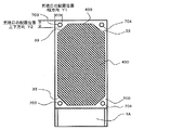
- the width in the left-right direction of the vacuum heat insulating material 400 provided on the back surface of the refrigerator 1 is smaller than the width between the storage chamber inner wall surfaces 791, 792 of the side wall 790 of the refrigerator 1.
- the filling ports (injection ports) 703 and 704 of a heat insulating material such as urethane provided in a plurality are not blocked, and the filling flow path of the heat insulating material such as urethane filled from the filling ports 703 and 704 is blocked. There is no such thing.
- the width in the left-right direction of the vacuum heat insulating material 400 provided on the rear surface of the refrigerator 1 is the width between the storage chamber inner walls of the side wall 790 of the refrigerator 1 (between the storage chamber inner wall left 791 and the storage chamber inner wall right 792). If the distance is equal to or smaller than (distance), it will not block the filling port or flow path of the heat insulating material such as urethane, so the urethane heat insulating material will be filled without interruption, so there will be no decrease in heat insulation performance.
- the distance is equal to or smaller than (distance)
- the vacuum heat insulating material 400 is equivalent to the arrangement position of the filling ports 703 and 704 of the heat insulating material such as urethane provided at the left and right end portions on the back side of the refrigerator 1 or the center side of the filling ports 703 and 704 (inward direction) ), The filling ports 703 and 704 of the urethane heat insulating material are not blocked by the vacuum heat insulating material 400, so that urethane filled from the filling ports 703 and 704, etc.
- the filling port of the heat insulating material such as urethane
- the filling port of the heat insulating material such as urethane
- urethane filled from 703 and 704 may obstruct or obstruct the flow of the vacuum heat insulating material 400 in the side wall 790, the convex portion 450, or between the vacuum heat insulating material 400 and the inner box 750.
- the side wall or the like is poorly filled with a heat insulating material such as urethane and the heat insulating performance is lowered.
- the vacuum heat insulating material 400 is filled on the left side (one side) so as not to protrude outward from the filling ports 703 and 704 of a heat insulating material such as urethane provided at the left and right end portions on the back side of the refrigerator 1.
- Insulating material such as urethane filled from the filling ports 703 and 704 is disposed within the range inside the port 703 and the right side (the other side) filling port 704, so that the heat insulating material inside the heat insulation box (between the inner box 750 and the outer box 710, For example, it does not hinder or disturb the filling into the side wall 790, the convex portion 450, between the vacuum heat insulating material 400 and the inner box 750, between the vacuum heat insulating material 400 and the outer box 710, etc.
- a high-performance heat insulation box or refrigerator in which the heat insulation performance does not deteriorate is obtained.
- the width of the vacuum heat insulating material 400 protrudes outside the filling ports 703 and 704 of heat insulating material such as urethane provided at the left and right end portions on the back side of the refrigerator 1 (the end position in the width direction of the vacuum heat insulating material 400 is In the case where the filling ports 703 and 704 such as urethane provided at the left and right end portions on the rear side of the refrigerator 1 are disposed outside the placement position), the filling ports 703 and 704 are closed with the vacuum heat insulating material 400.
- heat insulating material such as urethane provided at the left and right end portions on the back side of the refrigerator 1
- the vacuum heat insulating material 400 does not block at least a part of the filling ports 703 and 704, and a notch portion such as a notch or an opening is formed in the portion of the vacuum heat insulating material 400 facing the filling ports 703 and 704. 33 may be provided.
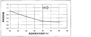
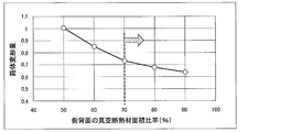
- the width of the vacuum heat insulating material 400 can be increased, so that the area of the vacuum heat insulating material 400 can be increased, and the vacuum heat insulating material with respect to the outer surface area of the heat insulating box or the back wall of the heat insulating box.
- the ratio (coverage ratio) of the arrangement area can be increased. Therefore, it is possible to improve the heat insulation performance. (For example, see FIGS. 12 and 22)
- a heat insulating material 701 such as urethane is filled between the inner box 750 and the outer box 710 forming the convex portion (or between the inner box 750 and the vacuum heat insulating material 400) or another part (urethane)
- the heat insulating material other than the heat insulating material is arranged to improve the strength of the heat insulating box 700.
- the inside of the convex portion 450 (for example, vacuum) Between the heat insulating material 400 and the inner box 750, near the end in the width direction of the vacuum heat insulating material 400, or near the convex portion 450, for example, outside the convex portion 450 (for example, inside the inner box 750 or outside the inner box 750). ) May be provided with a reinforcing member.
- This reinforcing member may be less affected by a member having poor thermal conductivity (for example, a resin member made of resin) than that made of metal, for example. Even if it is made of metal (aluminum, aluminum alloy, etc.), it is possible to suppress the loss of heat insulation performance, and the shape is rod-shaped (round bar or square bar) or pipe-shaped. Also good. Moreover, the structure which provides a rib etc. in the inner box 750 may be sufficient, and what can improve box strength, such as the twist strength of the heat insulation box 700, and bending strength, is sufficient.
- a member having poor thermal conductivity for example, a resin member made of resin
- the structure which provides a rib etc. in the inner box 750 may be sufficient, and what can improve box strength, such as the twist strength of
- the pipe 720 and the refrigerant pipe 725 in which the lead wires such as the control wiring and the power line are accommodated as a reinforcing member, and if the pipe 720 and the refrigerant pipe 725 are used as a reinforcing member, the reinforcement is separately performed.
- the reinforcing member can be disposed in the convex portion 450 or in the space between the inner box 750 and the outer box 710, and the design is improved because the reinforcing member is not directly visible to the user. Therefore, it is possible to obtain a heat insulating box, a refrigerator, and a device that are low in cost, highly reliable, and excellent in design.
- the concave portion 440 which is a portion where the inner box 750 and the vacuum heat insulating material 400 are directly attached via an adhesive (may be a self-adhesive foam heat insulating material), is a peripheral wall formed around the concave portion 440. Since it is recessed with respect to the convex portion 450 provided at the corner portion (for example, the side wall 790, the ceiling wall 740, or the partition wall 24), this concave portion may be used as the cold air passage 760.
- the cold air passage 760 corresponds to the refrigerator compartment cold air passage 50
- the cold air passage 760 is (When the storage room is the vegetable room 5, the cold air path 760 corresponds to the vegetable room cold air path).
- the opening portion of the second air passage component 764 having a U-shaped (or concave shape) opening portion is disposed so as to open to the storage chamber side, and the air passage cover
- the first air path component 762 is arranged so as to cover the U-shaped opening of the second air path component 764 and the opening of the second air path component 764 is closed by the first air path component 762.
- a cold air passage 760 in a sealed space can be formed.
- Both the first air path component 762 and the second air path component 764 are made of a heat insulating member such as polystyrene foam or resin, but the second air path component 764 disposed in the concave portion 440 is an air path rear surface member on the back side. 765, a side surface side air passage side member 766.
- An inner box 750 that forms a recess 440 is disposed on the back side of the member on the back side of the second air path component 764 (air path back member 765).
- the vacuum heat insulating material 400 is provided via an inner box 750 that forms the back wall 730 and an adhesive, and on the side surface side of the member on the side surface of the second air path component 764 (air path side surface member 766).
- a convex portion 450 formed by the inner box 750 is provided, and a heat insulating material 701 such as urethane is provided in the convex portion 450.
- the air path back surface member 765 and the air path side surface member 766 constituting the second air path component 764 can ensure heat insulating performance even if they do not have heat insulating properties.
- the heat insulation performance is ensured on the back side of the cold air passage 760 by the vacuum heat insulating material 400 disposed in the back wall 730, and the heat insulation performance is secured on the side surface side of the cold air passage 760 by the heat insulation material 701 in the convex portion 450.
- the air path back surface member 765 and the air path side surface member 766 constituting the second air path component 764 may be heat insulating materials such as polystyrene foam, they are made of resin or metal that does not have heat insulating performance.
- the member constituting the second air passage component 764 may be a heat insulating material such as a polystyrene foam having heat insulation properties, but even if it is a member made of resin or metal that does not have heat insulation properties, Adhesion of dew or the like to parts or the like forming the path 760 or dew generation due to dew generation can be suppressed.
- the first air passage component 762 is made of, for example, a heat insulating member having heat insulating properties such as foamed polystyrene or a resin, and suppresses the dew so that dew does not adhere to or occurs on the storage chamber side. Yes.
- the first air passage component 762 has a protruding portion (extension) having a width greater than the width in the left-right direction of the recess 440 or the width in the left-right direction of the U-shaped opening of the second air passage component 764.
- the protrusion (extension part) 763 closes the opening or recess 440 of the second air passage component 764 in a substantially sealed state to form a cold air passage 760, and the protrusion
- the first air path component 762 can be detachably fixed to the convex portion 450 or the second air path component 764.
- the first air passage component 762 only needs to close the opening of the second air passage component 764 to secure the cold air passage, so that only the opening of the second air passage component can be closed, and the recess 440 is also included.
- the attachment manufacture of the 1st air path component 762 will improve, and the design property will also improve.
- the cold air path components (for example, the first air path component 762 or the second air path component 764) forming the cold air path 760 can be used as a reinforcing member for improving the strength of the box.
- the box strength or the box rigidity for example, the torsion strength or the bending strength
- the first wind path component 762 or the second wind path component 764 is used as a reinforcing member to strengthen the box strength ( The box rigidity may be increased.
- the first air path component or the second air path component 764 is made of resin, it may be made to have a predetermined thickness so that the box strength can be obtained.
- the torsional strength and the bending strength may be improved by providing ribs in the width direction or the vertical direction in the first airway component 762 or the second airway component 764. If the strength or rigidity of the heat insulating box 700 is not a problem, the second air passage component 764 is omitted, and the recess 440 is directly used as the back wall and side wall of the cold air passage 760, and the opening of the recess 440 It is also possible to provide the first air path component 762 so as to cover the air.
- the second air channel component 764 is not required, so that the heat insulating box 700 and the refrigerator 1 having a simple structure and low cost can be obtained. can get.
- the first air path component 762 is provided so as to cover the concave portion 440, and the protruding portion (extending portion) 763 of the first air path component 762 may be detachably fixed to the convex portion 450. By directly fixing the (extension part) 763 to the convex part 450, the strength of the box is also improved.
- the recess 440 can be used as the cold air path 760.
- the first air passage component 762 may be used as a reinforcing member with increased rigidity by increasing the plate thickness or by providing a rib, and the heat insulation box strength can be improved.
- the cold air passage 760 is provided with one or a plurality of cold air supply ports (cold air outlets) 768 for supplying cold air into the storage room (for example, the refrigerator room 2 or the vegetable room 5).
- One or a plurality (at least one) of the cold air supply port (cold air outlet) 768 is provided in the first air channel component 762 or the second air channel component 764 so that the storage chamber can be efficiently cooled.
- the cold air supply port 768 is a side air outlet that blows out sideways in the storage chamber, a front air outlet that blows out forward, a side front oblique air outlet that can be blown in a diagonal direction between the side and the front, or an upper side and a front side.
- the upper front oblique blower outlet that can be blown in an oblique direction
- the lower front oblique blower outlet that can be blown in the downward and forward oblique directions
- the side upper oblique blower outlet that can be blown in the lateral and upward oblique directions
- a lateral lower oblique outlet is provided that can blow out laterally and obliquely downward.
- the vacuum heat insulating material 400 is provided on the back wall 730 of the heat insulating box 700 or the back surface of the refrigerator 1
- the side wall 790, the top wall 740, and the bottom wall 780 of the heat insulating box 700 are described.
- it may be provided on the side, top or bottom of the refrigerator 1.
- you may provide the vacuum heat insulating material 400 in the storage chamber door (For example, the refrigerator compartment door 7, the freezer compartment door 11, etc.) which covers the front opening of a storage chamber, In this case, the improvement of the heat insulation performance can be aimed at further.
- a cold air supply passage (cold air outlet) 768 is provided on a side surface (side surface of the first air passage component 762 which is the front cover) of the cold air passage 760.
- the cold air supply port 768 is provided with a protruding portion (extending portion) 763 of the first air passage component 762 on the end surface 451 on the front surface side of the convex portion 450.
- the size of the opening of the cold air supply port (cold air outlet) 768 is set.
- the front side of the convex part 450 with respect to the front side end face 769 of the first air path component 762 that is a cover.
- the side end face 451 is recessed on the back side (rear side), and a recessed portion (space between the protruding portion (extension portion) 763 and the side wall 790) 770 recessed on the back side can be effectively used as a storage space.
- the step 775 can be used to provide a cold air supply port (cold air outlet) 768, and by providing the step 775, the side of the step 775 (the side of the cold air supply 768) and the side wall 790. Since a storage space for storing stored items such as food can be provided in the space 770 between the first air passage part 762 and the extension part 763, the step part 775 can be formed. By providing a cold air supply port (cold air outlet) 768 in 775, stored items such as food stored or stored in a storage space which is a space 770 on the side of the stepped portion 775 can be efficiently cooled.
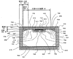
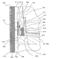
- FIG. 5 is a cross-sectional view of another refrigerator representing the first embodiment of the present invention, and is a cross-sectional view when the refrigerator is cut along a plane perpendicular to the vertical direction of the refrigerator 1.
- the same components as those in FIGS. 1 to 4 are denoted by the same reference numerals, and description thereof is omitted.
- the recess 440 is used as a cold air passage 760 in the same manner as in FIG. 4. That is, the concave portion 440 is formed by the side surface 452 of the convex portion 450 and the rear wall 730, and the inner box 750 that forms the inner surface (storage chamber side) of the rear wall 730 and the outer box 710 that forms the outer surface of the rear wall 730. Between the two, a plate-like vacuum heat insulating material 400 is provided. Here, although not shown, a plate-like vacuum heat insulating material 400 is also provided between the inner box 750 that forms the inner surface (the storage chamber side) of the side wall 790 and the outer box 710 that forms the outer surface of the side wall 790. May be.
- the cold air passage 760 provided in the back wall 730 or the recess 440 is provided on the first air passage component 762 that is a cover member having design properties, and on the back side (inner box 750 side) of the first air passage component 762,
- the second air passage component 764 having heat insulation properties is disposed in the recess 440.
- the first air path component 762 or the second air path component 764 as the cover member has an attachment portion (engagement portion), and the attachment portion (engagement) provided on the convex portion 450 or the back wall 730.
- the mounting portion is attached to the convex portion 450 or the back wall 730 by fitting into the portion) or engaging the mounting portions with a fixing member such as a screw.
- the cold air channel 760 is a cover provided so as to cover the storage chamber side opening of the second air channel component 764 or the storage chamber side opening of the recess 440 that is at least partially or entirely housed in the recess 440.
- the first air passage component 762 includes a concave portion 440 or a second air passage component 764, and the first air passage component 762 is the end surface 451 on the front surface side of the convex portion 450 or the air passage side surface of the second air passage component 764.
- the member 766 is fixed or held.
- the size of the stepped portion 775 formed by the extending portion 763 of the first airway component 762 is small, the stepped portion on the side surface formed by the extending portion 763 of the first airway component 762 Since it is difficult to provide the cold air supply port 768 in 775, the cold air supply port (cold air outlet) 768 is provided only on the front surface side of the first air passage component 762.
- the thickness of the protruding portion (extending portion) 763 of the first air passage component 762 can be reduced, the size of the stepped portion 775 can be reduced. Accordingly, the length in the depth direction in the storage chamber can be increased by the amount that the stepped portion 775 is reduced, and the storage capacity in the storage chamber can be increased.
- the shape of the first air passage component 762 that is a cover may be a plate shape as shown in FIGS. 4 and 5, but is a curved surface shape (for example, an arc shape or an arch shape) protruding toward the storage chamber. May be.
- the opening direction of the cold air supply port 768 can be provided not only in the front surface direction in the storage chamber but also in the curved portion, so that the cold air supply port 768 can be provided in an oblique direction. Since the degree of freedom of the position where the storage space is provided is improved, the storage chamber can be evenly cooled.
- the first air path component 762 may be fixed or held on the front end face 451 of the convex portion 450 or the second air path component 764.
- the assembly of the first air passage component 762 and the second air passage component 764 is stored or disposed in the recess 440 in a state in which the air passage component 764 is fixed to or held in advance with the first air passage component 762.
- the protruding portion (extending portion) 763 of the first air path component 762 may be fixed or held on the convex portion 450 (for example, the end surface 451 on the front surface side).
- the second air passage component 764 can be attached to the convex portion 450 in the storage chamber in a state in which the second air passage component 764 is fixed or held to the first air passage component 762 to form the cold air passage 760.
- the first air passage component 762 and the second air passage component 764 can constitute an assembly of the cold air passage 760, so that the cold air passage is detachable. 760 assemblies can be easily installed in a storage chamber (eg, convex portion 450).
- an adhesive which may be a foam heat insulating material having self-adhesiveness
- a first interposed member whose main purpose is adhesion is interposed between the vacuum heat insulating material 400 and the inner box 750.
- the cold air flow path 760 (first air flow path component)
- the second air passage component 764 or the assembly of the first air passage component and the second air passage component is attached to the recess 440
- the vacuum heat insulating material 400 may be damaged by screws or the like for fixing.
- the cold air passage 760 is attached to the convex portion 450, the cold air passage 760 is not attached to the concave portion 440 or the inner box 750 at a position facing the vacuum heat insulating material 400.
- Well Runode, reduction and less heat-insulating main body degradation of high heat insulating performance eliminates reliability hurt like outer cover material of the vacuum heat insulating material 400, refrigerators, appliance is obtained.
- the cold air duct 760 if the first air duct component 762 is attached to the convex portion 450 so as to cover the recess 440, the cool air duct 760 is formed without providing the second air duct component 764. Therefore, it is possible to obtain a heat-insulated box or a refrigerator that has a small number of parts, is easy to assemble at low cost, and is highly reliable.
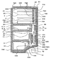
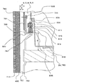
- FIG. 6 is a cross-sectional view of another refrigerator representing the first embodiment of the present invention, and is a cross-sectional view when the refrigerator is cut along a plane perpendicular to the vertical direction of the refrigerator 1.
- the same parts as those in FIGS. 1 to 5 are denoted by the same reference numerals, and description thereof is omitted.
- a concave portion 440 is formed by the side surface 452 of the convex portion 450 and the rear wall 730, and an inner box 750 that forms the inner surface (storage chamber side) of the rear wall 730 and an outer surface that forms the outer surface of the rear wall 730.
- a plate-like vacuum heat insulating material 400 is provided between the box 710 and the box 710.
- a plate-like vacuum heat insulating material 400 is also provided between the inner box 750 that forms the inner surface (the storage chamber side) of the side wall 790 and the outer box 710 that forms the outer surface of the side wall 790. Yes.
- the cold air passage 760 provided in the back wall 730 or the recess 440 is provided on the first air passage component 762 that is a cover member having design properties, and on the back side (inner box 750 side) of the first air passage component 762,
- the second air passage component 764 having heat insulation properties is disposed in the recess 440.
- the first air passage component 762 or the second air passage component 764 that is the cover member has an attachment portion (engagement portion) and is fitted into the attachment portion (engagement portion) provided on the back wall.
- the attachment portions are attached to the back wall 730 by engaging the fixing members such as screws.
- a space 770 is provided between a side portion (side surface) 766 of the cold air passage 760 and a side surface (side portion) 452 of the convex portion 450, and this space 770 can be used as a storage space. It is possible to increase the storage volume of storage items (for example, the refrigerator compartment 2).
- the second air passage component 764 constituting the cold air passage 760 has a U-shaped cross section with an opening in the cold air flow direction (for example, the vertical direction of the refrigerator 1). It is installed in the storage chamber of the refrigerator 1 so that the letter-shaped opening faces the back side of the refrigerator 1 (arranged in the recess 440 on the back of the storage chamber).
- the first air passage component 762 is fixed to the convex portion 450 in a state of being pressed by the first air passage component 762 so that the U-shaped opening of the second air passage component 764 is in contact with the inner box 750 that forms the recess 440.
- the cold air path 760 is configured by the second air path component 764 and the inner box 750 by being held.
- the second air passage component 764 is not necessary, and therefore the first air passage component.
- the cold air path 760 can be configured by the 762 and the inner box, and a low-cost refrigerator and equipment can be obtained.
- the second air passage component 764 has an opening having a U-shaped cross section with respect to the flow direction of the cold air.
- the second air passage component 764 does not have to be U-shaped separately and only needs to be able to configure the cold air air passage. It is only necessary that the cross-sectional shape with respect to the flow direction is square or elliptical and a cold air passage is formed inside.
- the cross-sectional shape of the internal cold air passage may also be square or elliptical.
- a circular or elliptical cool air passage is more efficient because the flow resistance is smaller and more efficient, and the elliptical shape elongated in the width direction than the circular shape can reduce the length in the depth direction. The amount can be reduced and the storage volume can be increased.
- first air passage component 762 or the second air passage component 764 may be directly fixed to or held in the inner box 750 that forms the recess 440, but the cold air passage 760 may be formed as shown in FIG.
- the first air passage component 762 is provided with a protrusion (extension part) 763, and the protrusion 763 extends longer than that in the case of FIG. 4 so that the protrusion (extension part) 763 straddles the space 770. You may enable it to fix to the convex part 450. FIG. In this case, depending on the place where the protruding portion (extending portion) 763 is fixed, the storage volume of the space 770 may be reduced by the protruding portion 763.
- the top wall 740 or the bottom wall provided above and below the cold air passage 760 The projecting portion (extending portion) 763 extends to the vicinity of the partition wall 24 or the shelf 80 for partitioning between 780 or the storage chambers, and is fixed or held on the convex portion 450. Can be reduced (a situation in which a tall stored item cannot be stored by hitting the protruding portion (extending portion) 763) can be suppressed.
- the components (first air channel component or second air channel component) forming the cold air air passage 760 partition the vicinity of the top wall 740 or the bottom wall 780 provided between the upper and lower sides of the cold air air passage 760 or between the storage chambers. You may make it fix or hold
- FIG. (For example, when the protruding portion 763 is provided in the vertical center of the space 770 or below the approximate center, the stored item hits the protruding portion 763 and cannot be stored when a tall stored item is stored in the space 770.
- the stored items are stored in the space 770. Also, the protrusion 763 is less likely to get in the way, and the storage capacity can be increased.
- the first air passage component 762 that is a cover that covers at least a part of the back surface of the storage chamber includes at least a part of the cold air passage 760 or an air passage cover portion that covers at least a part of the cold air passage 760, A back cover part extending in the width direction (left-right direction or side wall 790 direction) from the air path cover part and covering at least a part of the back wall 730 or the recess 440, and connected to the back cover part or integrally formed with the back cover part You may make it provide the side surface cover part which covers at least one part of the side wall 790.
- the side cover portion may be attached by being fixed or held on the inner box 750 forming the side wall 790 or the convex portion 450. If it does in this way, since at least one part of the back wall 730, the side wall 790, and the convex part 450 can be covered with the 1st air path component 762 which is a cover, design property improves and assembly property also improves.
- the first air passage component 762 that is a cover that covers at least a part of the back surface of the storage chamber includes at least a part of the cold air passage 760 or an air passage cover portion that covers at least a part of the cold air passage 760, A back cover portion extending in the width direction (left-right direction or side wall 790 direction) from the air passage cover portion and covering at least a part of the back wall 730 or the recess 440, and connected to the air passage cover portion or integrally formed with the air passage cover portion.
- an upper and lower wall cover portion that covers at least a part of the partition wall 24 (including the ceiling wall 740 or the bottom wall 780) provided in the vertical direction of the back wall 730 may be provided.
- the upper and lower wall cover portions may be attached to the inner box 750 that forms the partition wall 24 (including the ceiling wall 740 or the bottom wall 780) provided in the vertical direction of the back wall 730.
- the partition wall 24 including the ceiling wall 740 or the bottom wall 780
- Cold air that has been generated by the cooler 13 and has flowed through the cold air passage 760 or the like is stored in the cold air passage 760 or a part that forms the cold air passage 760 (such as the first air passage component or the second air passage component).
- One or a plurality of cold air supply ports 768 for supplying the inside of the room are provided on the side surface or the front surface of the cold air passage 760. Is provided at a position where the stored items such as food in the storage room and the stored items can be cooled effectively.
- the vertical position of the cold air supply port on the side and the cold air supply port on the front surface may be the same.
- the height position of the cool air supply port 768 provided in the left and right side surfaces may be the same height, it is possible to cool from a position having a different height by disposing the height positions. Storing and storing items such as food can be cooled evenly and efficiently.
- the width dimension of the vacuum heat insulating material 400, the installation position in a heat insulation box or a refrigerator are equivalent to FIG.4 and FIG.5. That is, the width in the left-right direction of the vacuum heat insulating material 400 provided on the back wall 730 of the refrigerator 1 is, for example, smaller than the width between the storage chamber inner walls 791 and 792 of the side wall 790 of the refrigerator 1.
- the filling flow path of the heat insulating material such as urethane filled from the filling ports 703 and 704 of the urethane heat insulating material provided in is not blocked.
- the vacuum heat insulating material 400 is located outside the filling ports 703 and 704 of a heat insulating material such as urethane provided on the left and right end portions of the rear surface of the refrigerator 1 (for example, the openings of the filling ports 703 and 704 are not opened). Insulates or obstructs the flow of heat insulating material such as urethane flowing into the heat insulating box (for example, the side wall 790) from the unoccluded position or the opening of the filling ports 703 and 704 into the side wall 790 or the back wall 730. It is sufficient if it is arranged at a position where it does not.
- a heat insulating material such as urethane provided on the left and right end portions of the rear surface of the refrigerator 1 (for example, the openings of the filling ports 703 and 704 are not opened). Insulates or obstructs the flow of heat insulating material such as urethane flowing into the heat insulating box (for example, the side wall 790)
- filling is performed by placing the left and right filling ports (the left filling port 703 and the right filling port 704) on the center side (inside) in the width direction, and the filling ports 703 and 704 at positions where the vertical positions do not overlap.
- a heat insulating material such as urethane filled in the heat insulating box (the space 315 between the inner box 750 and the outer box 710, for example, in the side wall 790 or the back wall 730) from the ports 703 and 704 is formed in the heat insulating box (inner box 750).
- the space 315) between the outer box 710 and the outer box 710 is not obstructed or obstructed, so there is no insufficient filling or density of the heat insulating material, and a high performance heat insulating box or refrigerator that does not deteriorate the heat insulating performance. can get.
- the recess 440 which is a direct bonding site where the vacuum heat insulating material 400 and the inner box 750 are directly bonded via an adhesive (may be a self-adhesive foamed heat insulating material),
- an adhesive may be a self-adhesive foamed heat insulating material
- it is recessed in the depth direction (rear side).
- the convex part 450 which is a reinforcement member interposition part protrudes ahead in the depth direction with respect to the concave part 440 which is a direct adhesion part by the stepped part 776.
- the concave portion 440 which is a direct bonding portion where the vacuum heat insulating material 400 and the inner box 750 are directly bonded via an adhesive such as a self-adhesive foam heat insulating material, is the height (thickness) of the cold air passage 760.
- the concave portion 440 is recessed in the depth direction (rear side) with respect to the front end surface 769 of the cold air passage 760.
- the front side end surface 769 of the cold air passage 760 protrudes forward in the depth direction with respect to the adhesion portion by the level difference.
- the heat insulating box, the refrigerator, the cool box, and the showcase that are formed from the inner box 750 and the outer box 710 and have the vacuum heat insulating material 400 between the inner box 750 and the outer box 710.
- a direct bonding portion (a vacuum bonding material 400 provided in a back wall 730 of a room (for example, a storage room) is directly attached to the inner box 750 with an adhesive such as a self-adhesive foam heat insulating material (In the figure, a concave portion 440) and a reinforcing member intervening portion (a convex portion 450 in the figure) where a heat insulating material such as urethane, which is a reinforcing member for improving the strength of the box body, is interposed between the vacuum heat insulating material 400 and the inner box 750.
- an adhesive such as a self-adhesive foam heat insulating material (In the figure, a concave portion 440) and a reinforcing member intervening portion
- the vacuum heat insulating material 400 and the outer box 710 are directly attached with a second adhesive such as hot melt or double-sided adhesive tape. Since the second adhesive such as hot melt and double-sided tape can be applied or pasted in advance to the vacuum heat insulating material 400 side or the outer box 710 side, the thickness of the adhesive can be reduced. It is better to use a foam heat insulating material having self-adhesiveness between the vacuum heat insulating material 400 and the inner box 750, because there is a risk that uneven bonding or the like may occur.
- a reinforcing member intervening portion for example, convex portion 450
- a direct adhesion portion for example, concave portion 440
- Reinforcement member intervening portion for example, convex portion 450 provided at the left and right end portions in the direction and a direct adhesion portion (for example, concave portion) provided between the left and right reinforcing member intervening portions so as to be sandwiched between the left and right reinforcing member intervening portions 440
- the convex part 450 (reinforcement member interposition part) is formed in the left-right direction on the back of the storage chamber
- the concave part 440 direct adhesion part
- the concave portion 440 and the convex portion 450 are provided over almost the entire height range in the vertical direction in the storage chamber from the viewpoint of securing the strength of the box or securing the cold air passage.
- the vacuum heat insulating material 400 and the outer box 710 are brought into direct contact or contact with each other via the second adhesive at the position facing the concave portion 440, the outer box 710 and the vacuum heat insulating material 400 are brought into contact with each other.
- a heat insulating material is not required between the two, and the volume of the storage chamber can be increased as compared with the case where a heat insulating material is interposed.
- part for example, recessed part 440
- the vacuum heat insulating material 400 is provided with heat insulating performance and strength at the location where the vacuum heat insulating material 400 is disposed (for example, the concave portion 440), and therefore, between the inner box 750 and the vacuum heat insulating material 400.
- fluidity when fluidity is required as an adhesive, it may be bonded by foaming after flowing into the space 315 in a two-phase state using a hard urethane foam having self-adhesiveness.
- the concave portion 440 can be used as the cold air passage 760 for blowing the cold air that cools the storage chamber, the concave portion 440 on the back surface of the storage chamber that is difficult to reach by the user can be effectively used.
- the storage capacity in the storage chamber can be used efficiently.
- the vacuum heat insulating material 400 having a predetermined strength (bending strength and bending degree) is used, and the convex portion 450 is placed in the storage chamber at a predetermined width (preferably enough to ensure torsional strength and bending strength).
- the required strength of the heat insulating box 700 and the refrigerator 1 can be obtained, and the torsional strength and the bending strength in the front-rear direction and the left-right direction can be ensured. And the refrigerator 1 is obtained. If the required strength of the heat insulating box 700 and the refrigerator 1 can be obtained and the torsional strength and the bending strength in the front-rear direction and the left-right direction can be secured, the convex portion 450 does not need to be provided continuously in the up-down direction. Alternatively, a plurality of locations may be provided intermittently.
- a convex portion 450 made of a heat insulating material 701 such as urethane disposed in the vertical direction is formed on the left and right end portions (width direction end portion side) on the back of the storage chamber.
- the heat insulation box 700 and the refrigerator 1 are deformed, and the storage room door (for example, the rotating (hinge type) refrigerating room door 7) provided on the front surface of the storage room (for example, the refrigerating room 2) is tilted or opened, for example,
- the storage room door for example, the rotating (hinge type) refrigerating room door
- the left and right doors (7A, 7B) does not tilt and cause a positional shift, so that the storage room door can be opened and closed smoothly.
- the left and right storage room doors are not misaligned.
- the heat insulating box 700 is deformed so that the inner walls (left and right side walls) 791 and 792 of the storage room (for example, the ice making room 3, the switching room 4, the vegetable room 5 and the freezing room 6) are transformed. Since the installation height of the provided rail for the drawer type case does not differ or tilt on the left and right sides, the case can be inserted and removed smoothly.
- the vacuum heat insulating material 400 has a bending elastic modulus of 20 MPa or more and the convex portion 450.
- the heat insulating material such as urethane the one having a flexural modulus of 13.0 MPa or more (preferably 15 MPa or more) and a density larger than 60 kg / m 3 (preferably 62 kg / m 3 or more) is used.
- the thickness of the urethane is reduced in order to reduce the wall thickness, the density of the urethane increases and the flexural modulus also increases, so that the box strength can be increased, but the heat insulation performance deteriorates as the density increases. For this reason, it has been difficult to make the thickness of the urethane thinner than a predetermined value (for example, 15 mm).
- the vacuum heat insulating material 400 having a large bending elastic modulus of 20 MPa or more since the vacuum heat insulating material 400 having a large bending elastic modulus of 20 MPa or more is used, heat insulating performance and strength are provided in the portion (box or wall) where the vacuum heat insulating material 400 is disposed. It is possible to have both of these in the vacuum heat insulating material 400, and even when a heat insulating material such as urethane is filled between the outer box and the inner box, the urethane is insulated at the portion where the vacuum heat insulating material is disposed. Can be used as an adhesive without having to be used as a heat insulating material.
- a heat insulating material such as urethane can be used as an adhesive for bonding the vacuum heat insulating material 400 and the inner box 750 or the vacuum heat insulating material 400 and the outer box 710, the thickness of the urethane can be reduced and the heat insulating performance of the urethane can be reduced. There is no problem even if it drops.
- the coverage of the vacuum heat insulating material 400 the ratio of the arrangement area of the vacuum heat insulating material 400 to the surface area of the heat insulating box 700 and the door
- the filling rate of the vacuum heat insulating material 400 between the outer box 710 and the inner box 750.
- the heat insulating box 700 By increasing the volume ratio of the vacuum heat insulating material 400 to the space 315 to a predetermined value or more (for example, 40% or more), even if there is a portion where the vacuum heat insulating material 400 is not provided, the heat insulating box 700 is obtained. Heat insulation performance and strength can be secured.
- the strength and heat insulation of the heat insulating box 700 by the vacuum heat insulating material 400 is provided, a rigid urethane foam is used as an adhesive mainly for bonding between the vacuum heat insulating material 400 and the outer box 710 or between the vacuum heat insulating material 400 and the inner box 750. Therefore, the thickness of the urethane can be reduced, and it is not necessary to consider the deterioration of the heat insulating performance of the urethane.
- the volume in the storage chamber can be increased by reducing the thickness of the urethane and reducing the wall thickness.
- a second adhesive such as hot melt or double-sided tape between the outer box 710 and the vacuum heat insulating material 400 or between the inner box 750 and the vacuum heat insulating material 400, Since the wall thickness can be reduced, the volume in the storage chamber can be increased.
- the thickness of the rigid urethane foam when used as an adhesive used between the vacuum heat insulating material 400 and the outer box 710 or between the vacuum heat insulating material 400 and the inner box 750 is a predetermined value or less or a vacuum. Since the wall thickness can be reduced by reducing the thickness of the heat insulating material 400, the volume in the storage chamber can be increased.
- the thickness of the rigid urethane foam used mainly for adhesion to either one of the vacuum heat insulating material 400 and the outer box 710 or between the vacuum heat insulating material 400 and the inner box 750 is vacuum heat insulating.
- the thickness is smaller than the thickness of the material 400, the effect of reducing the wall thickness can be obtained, but the thickness of the rigid urethane foam between the vacuum heat insulating material 400 and the outer box 710 and the space between the vacuum heat insulating material 400 and the inner box 750 can be obtained. If the total thickness of the hard urethane foam is made smaller than the thickness of the vacuum heat insulating material 400, the wall thickness can be further reduced, so that the volume in the storage chamber can be increased.
- rigid urethane foam is used as an adhesive used between the vacuum heat insulating material 400 and the outer box 710 or between the vacuum heat insulating material 400 and the inner box 750, and the thickness of the urethane is made as much as possible. Although it is thinned, not only between the vacuum heat insulating material 400 and the outer box 710, or between the vacuum heat insulating material 400 and the inner box 750, but also a portion that is filled only with urethane without the vacuum heat insulating material 400 ( Even within the wall), the same rigid urethane foam may be used.
- the vacuum heat insulating material 400 does not exist in a portion (for example, a part in the wall or the convex portion) where only the urethane where the vacuum heat insulating material 400 is not provided is filled, the hard urethane corresponding to the thickness of the vacuum heat insulating material 400 is present. Therefore, the heat insulation thickness of urethane can be increased. Therefore, the thickness of the urethane where the vacuum heat insulating material 400 does not exist is larger than the thickness of the urethane filled between the vacuum heat insulating material 400 and the outer box 710 or between the vacuum heat insulating material 400 and the inner box 750.
- the vacuum heat insulating material 400 Since the density of urethane in the portion where the vacuum heat insulating material 400 is not disposed can be made smaller than the density of urethane in the region where the vacuum heat insulating material 400 is disposed, the vacuum heat insulating material 400 is not disposed. The heat insulation performance of the urethane at the site is improved, and the predetermined performance can be secured. Further, since the thickness of the urethane can be increased at a portion where the vacuum heat insulating material 400 is not provided, the box strength is also improved.
- the coverage of the vacuum heat insulating material 400 (the ratio of the area of the vacuum heat insulating material 400 to the heat insulating box 700 and the surface area of the door).
- the filling rate of the vacuum heat insulating material 400 (the volume ratio of the vacuum heat insulating material 400 to the space 315 between the outer box 710 and the inner box 750) is increased to a predetermined value or more.
- the thickness of the urethane heat insulating material is reduced to make the strength of the urethane heat insulating material have a bending elastic modulus of 13.0 MPa or more. A thing enlarged to (preferably 15 MPa or more) can be used.
- the density of the urethane heat insulating material can be larger than 60 kg / m 3 (preferably 62 kg / m 3 or more)
- the thickness of the urethane can be reduced, and the wall thickness of the heat insulating box 700 can be reduced. It can also be reduced.
- the density of the insulating material such as urethane (for example, rigid urethane foam) (the density after foaming in the case of the foamed heat insulating material) is 100 kg / m 3 or less (preferably). Or less than 90 kg / m 3 ).
- FIG. 7 is a cross-sectional view of another refrigerator representing the first embodiment of the present invention, and is a cross-sectional view when the refrigerator is cut along a plane perpendicular to the vertical direction of the refrigerator 1.
- the same parts as those in FIGS. 1 to 6 are denoted by the same reference numerals, and description thereof is omitted.
- a concave portion 440 is formed by the side surface 452 of the convex portion 450 and the rear wall 730, and an inner box 750 that forms the inner surface (storage chamber side) of the rear wall 730 and an outer surface that forms the outer surface of the rear wall 730.
- a plate-like vacuum heat insulating material 400 is provided between the box 710 and the box 710.
- a plate-like vacuum heat insulating material 400 is also provided between the inner box 750 that forms the inner surface (the storage chamber side) of the side wall 790 and the outer box 710 that forms the outer surface of the side wall 790. May be.
- the cold air path 760 provided in the convex portion 450 is provided on the first air path part 762 that is a cover member having design properties and the back side (outer box 710 side) of the first air path part 762, and has a heat insulation property.
- the second air passage component 764 is disposed in the convex portion 450.
- the first air path component 762 or the second air path component 764 as the cover member has an attachment portion (engagement portion), and the attachment portion (engagement portion) provided on the back wall 730 or the side wall 790. ) Or the attachment portions are engaged with each other by a fixing member such as a screw.
- a cold air passage 760 is formed in the convex portion 450, and one, two, or a plurality of the convex portions 450 are provided on the side of the rear end in the width direction of the storage chamber.
- the cold air channel 760 is configured by a second air channel component 764 (or the second air channel component 764 and the vacuum heat insulating material 400) having a U-shaped cross section or a substantially rectangular cross section, and the convex portion 450 is connected to the second air channel component 764.
- the inner box 750 is provided so as to cover the storage chamber side of the second air passage component 764. That is, a cold air passage 760 is interposed between the vacuum heat insulating material 400 and the inner box 750.
- the cold air passage 760 is provided with one or a plurality of cold air supply ports 768 for supplying cold air into the storage chamber.
- the opening is disposed so as to face the vacuum heat insulating material 400 side, and the U-shaped opening is vacuumed.
- the cold air path 760 is configured by the heat insulating material 400 being closed.
- the U-shaped opening is not arranged so as to face the vacuum heat insulating material 400 side, but is arranged so as to face the side wall 790 side or the storage chamber side, and the U-shaped opening is made of a heat insulating material such as polystyrene foam.
- the cold air path 760 may be configured by blocking the air.
- the outer shape of the cross section of the second air passage component 764 may be a rectangular shape, a circular shape (circular tube shape), or an oval shape, and any shape may be used as long as the cool air air passage 760 is formed inside.
- the circular or elliptical shape may have less flow resistance. Since the height of the oval shape elongated in the width direction can be made smaller than that of a circle, the protruding height into the storage chamber can be reduced, so that the effective volume can be increased and the usability is good.
- the second air passage component 764 has a shape having no opening other than the cold air supply port 768 such as a rectangular shape, a circular shape (circular tube shape), or an elliptical shape
- the second air passage component The cold air path 760 may be formed by only 764.
- the second air passage component 764 forming the cold air passage 760 has a cross-sectional shape having a predetermined torsional strength or bending strength (for example, the U-shape or the cross-sectional outer shape is rectangular, circular (circular tubular), or elliptical. If a member of shape or the like is used, the strength of the convex portion 450 can be improved by providing the cold air passage 760 in the convex portion 450, and the box strength can be improved. However, when a member having a U-shaped cross section is used for the second air path component 764, the U-shaped opening may be opened or narrowed and the strength may be insufficient with respect to twisting or bending of the box.
- the openings of the second air path component 764 may be connected between the openings so that the openings are not opened or narrowed by another member (for example, a plate-like member, a rod-like member, or a rib member). The strength may be ensured by closing the opening.
- the cold air passage 760 that functions as a reinforcing member is provided instead of filling the heat insulating material 701 in the convex portion 450. Therefore, in the present embodiment, in a device such as a heat insulating box or a refrigerator that is formed of the inner box 750 and the outer box 710 and includes the vacuum heat insulating material 400 between the inner box 750 and the outer box 710, the inside of the storage chamber The strength of the box is improved between the directly bonded portion (recessed portion 440 in the figure) where the vacuum heat insulating material 400 is directly attached to the inner box 750 with an adhesive or the like on the back surface, and the vacuum heat insulating material 400 and the inner box 750.
- a reinforcing member interposed portion in which a cold air passage 760 as a reinforcing member is interposed.
- This reinforcing member intervening portion is provided at a corner portion of the back wall 730 and the side wall 790.
- the vacuum heat insulating material 400 and the outer box 710 are directly attached with a second adhesive such as hot melt or double-sided tape.
- the adhesive which is the first interposed member between the vacuum heat insulating material 400 and the inner box 750
- a hard urethane foam having self-adhesiveness may be used as an adhesive.
- the thickness of the urethane is preferably smaller than the thickness of the vacuum heat insulating material 400, and is preferably about 11 mm or less.
- the volume is preferably smaller than 10 mm, preferably about 6 mm or less.
- the vacuum heat insulating material 400 having a bending elastic modulus of 13 MPa or more, and also the heat insulating material 701 filled in the convex portion 450.
- the flexural modulus is preferably 13 MPa or more, and the density is preferably larger than 60 kg / m 3 .
- the density of heat insulating material such as urethane (such as rigid urethane foam) is too high, (1) cost increases due to increased urethane injection amount, and (2) urethane leakage occurs due to increased urethane injection pressure. (3) Mold for suppressing deformation of box and box holding member due to increase in foaming pressure at the time of urethane foaming etc.
- the density of the insulating material such as urethane (for example, rigid urethane foam) (the density after foaming in the case of the foamed heat insulating material) is 100 kg / m 3 or less (preferably). Or less than 90 kg / m 3 ).
- FIGS. 8 is a cross-sectional view of another refrigerator representing Embodiment 1 of the present invention, and is a cross-sectional view when the refrigerator is cut along a plane perpendicular to the vertical direction of the refrigerator 1 (FIGS. 4 to 7). The same).
- FIG. 9 is a front view of the refrigerator 1 as viewed from the front when the front opening / closing door of the refrigerator 1 representing Embodiment 1 of the present invention is removed
- FIG. 10 is a side cross-sectional view of the refrigerator 1 illustrating Embodiment 1 of the present invention.
- FIG. 8 to 10 the same parts as those in FIGS. 1 to 7 are denoted by the same reference numerals, and the description thereof is omitted.
- the convex portion 450 is substantially triangular, and the side surface of the convex portion 450 corresponds to the hypotenuse 456.
- the back wall side edge part 798 which is one end is connected with the back wall 730
- the side wall side edge part 797 which is the other end is connected with the side wall 790.
- a concave portion 440 is formed by the oblique side 456 corresponding to the side surface of the convex portion 450 and the back wall 730, and an inner box 750 that forms the inner surface (storage chamber side) of the rear wall 730 and an outer surface that forms the outer surface of the rear wall 730.
- a plate-like vacuum heat insulating material 400 is provided between the box 710 and the box 710.
- a plate-like vacuum heat insulating material 400 is also provided between the inner box 750 that forms the inner surface (the storage chamber side) of the side wall 790 and the outer box 710 that forms the outer surface of the side wall 790. May be.
- the cold air passage 760 provided in the back wall 730 or the recess 440 is provided on the first air passage component 762 that is a cover member having design properties, and on the back side (inner box 750 side) of the first air passage component 762,
- the second air passage component 764 having heat insulation properties is disposed in the recess 440.
- the first air path component 762 or the second air path component 764 as the cover member has an attachment portion (engagement portion), and the attachment portion (engagement) provided on the convex portion 450 or the back wall 730.
- the mounting portion is attached to the convex portion 450 or the back wall 730 by fitting into the portion) or engaging the mounting portions with a fixing member such as a screw.
- a concave portion 440 is formed on the back surface of the storage chamber, and a part of the concave portion 440 in the width direction (for example, a substantially central portion in the width direction) is used as the cool air passage 760.
- the cold air passage 760 may be a cold air passage 50 for the refrigerator compartment that supplies the cold air to the refrigerator compartment 2, and supplies cold air to the electrostatic atomizer (mist device) 200 or from the electrostatic atomizer 200.
- the mist is used as a cold air passage for supplying the mist together with cold air to a refrigerating room as a storage room.
- the cold air passage 760 includes a second air passage component 764 provided at a substantially central portion of the recess 440 and a first air passage component 762 that is a cover provided so as to cover the second air passage component 764.
- the first air passage component 762 has a U-shaped cross section with an opening, and includes a front surface portion 761 and a side surface portion 767.
- First airway component (for example, airway cover) 762 is at least partially in contact with fixing protrusion 910 which is a protrusion provided in recess 440 so that inner box 750 protrudes toward the storage chamber.
- the side surface portion is disposed, and the side surface portion or the front surface portion is fixed or held by the fixing protrusion 910.
- the inner surface of the side surface portion of the first air passage component 762 is at least partially in contact with the outer surface of the protrusion 910, and the first air passage component 762 is formed by a screw, a hook structure, a fitting structure, or the like. Is fixed or held to form a cold air passage 760.
- the shape of the first air passage component 762 shows a case of a U-shaped cross section, but may be a substantially semicircular shape, a curved surface shape (arch shape), a substantially V shape, or the like.
- the first air passage component 762 includes a protrusion 910 or an inner box (wall surface) 750 or a shelf 80 or a partition wall (for example, a rear wall 730, a side wall 790, a top wall 740, a bottom wall 780, a storage chamber) that forms a storage chamber.
- any other shape as long as the cool air duct 760 can be formed.
- the cold air passage 760 is connected to the cooler room 131 via a refrigerator room damper 55 which is an air volume adjusting means.
- the cold air generated by the cooler 13 disposed in the cooler chamber 131 is cooled by the cool air circulation fan (internal fan) 14 disposed in the cooler chamber 131, and the refrigerator compartment serving as an air volume adjusting means. It is carried to the cold air path 760 which is the cold air path 50 for the refrigerator compartment through the damper 55.
- the cold air carried to the cold air passage 760 is supplied into the storage chamber (for example, the refrigerator compartment 2) from the cold air supply port 768 provided in the first air passage component 762, the second air passage component 764, or the fixing projection 910. Supplied.
- one or a plurality (at least one) of cold air supply ports (cold air outlets) 768 into the storage chamber are provided on the front surface portion or the side surface portion of the first air passage component 762.
- the second air path component 764 one or a plurality (at least one) is provided on the front surface, side surface, or back surface of the second air path component 764.
- the cold air supply port 768 is provided in the front surface portion of the first air path component 762 so as to penetrate the front surface portion of the second air path component 764.
- the cold air supply port 768 is provided so as to communicate (or penetrate) the side surface portion of the air passage component 764, in addition to the cold air supply from the front surface portion, the cold air can be supplied also from the side into the storage chamber, so evenly It can be supplied efficiently.
- the cold air supply port of the first air passage component 762 and the cold air supply port of the second air passage component 764 do not need to be provided at the same position (communication position), and may be provided at different positions (not communication positions). good.
- the cold air supply port of the first air passage component 762 is provided on the front surface, and the cold air supply port of the second air passage component is a portion (front surface) whose vertical position is different from the position of the cold air supply port of the first air passage component. Part, side part) or even at the same height position, the left and right direction may be provided at different positions (side part).
- the front side end surface 769 of the front surface portion 761 of the first air passage component 762 and the recess 440 (storage chamber rear wall) are different in height from the storage chamber side (front direction of the refrigerator 1). There is a level difference (a level difference part 775) corresponding to the difference.
- a cold air supply port (opening, notch, etc.) 768 is not provided in the stepped portion 775 (for example, the side surface portion 767 or the protruding portion 910 of the first airway component 762 which is a member forming the outline of the cold airway 760).
- the front-side end surface 769 (thickness (height) projecting to the inside (storage room side)) of the first air passage component 762 can be reduced by the amount corresponding to the opening or notch of the cold air supply port 768, and the step portion The amount of protrusion of 775 to the inner side can be reduced. Accordingly, the length in the depth direction in the storage chamber can be increased by the amount that the stepped portion 775 is reduced, and the storage capacity in the storage chamber can be increased.
- the protrusion 910 are provided in the width direction (right protrusion and left protrusion as viewed from the front opening of the refrigerator 1), and the space between the left and right protrusions 910 is the second recess 441.
- the second recess 441 forms a groove shape in the vertical direction.
- the protrusion 910 is formed by the inner box on the back of the storage chamber forming the recess 440 protruding toward the storage chamber, and is provided continuously or intermittently in the vertical direction (for example,
- the protrusions 910 are provided in at least two locations substantially parallel to the vertical direction so as to form a groove shape (second recess 441).
- the protrusion 910 may be formed separately from the inner box 750.
- the inner surface side of the side surface portion 767 of the first air passage component 762 is fitted to the outer surface of the protrusion 910 that forms the second recess 441 (outer surface of the protrusion 910 that forms the groove shape), a hook structure or a screw. It is held or fixed by etc. That is, the concave / convex fitting structure that is held or fixed by the concave / convex fitting, or the fixing member (or holding means) that has the protruding hook portion and is held or fixed when the hook portion is hooked on the concave portion or the convex portion is the first air passage.
- the first air path component 762 is fixed or held to the protrusion 910 that forms the second recess 441.
- the first air passage component 762 is provided with a hook portion
- the projection portion 910 is provided with a concave portion or a convex portion at a position facing the hook portion, whereby the first air passage component 762 is formed with the second concave portion 441.
- the first air passage component 762 is fixed to or held by the protrusion 910 with a simple configuration in which the protrusion 910 is lightly pressed.
- At least two projections 910 provided in the vertical direction at the substantially central portion of the back surface of the refrigerator 1 in the width direction (left-right direction) and the storage chamber side of the back wall 730 are formed.
- the space (the width of the refrigerator 1) surrounded by the second recess (groove shape) 441 and the first air passage component 762 (for example, a U-shaped member having a U shape or a curved member having an arch shape).
- a space provided in the vertical direction is formed in a substantially central part in the direction.
- the space surrounded by the second concave portion 441 and the first air passage component 762 may be used as the cold air passage 760.
- the second concave portion 441 and the first air passage component 762 The second air passage component 764 may be housed in the space surrounded by, and this second air passage component 764 may be used as the cold air passage 760.
- the projecting portion 910 or the side surface portion 767 of the first air passage component 762 does not need to be continuous in the vertical direction, as long as the air passage can be formed, and cool air in the air passage can be stored in a storage chamber (for example, refrigeration). It is only necessary to form a cold air supply port 768 that can be supplied into the chamber 2 or the like.
- a plurality of protrusions 910 are provided intermittently in the vertical direction of the refrigerator 1 and no protrusions are provided between the plurality of protrusions provided intermittently in the vertical direction (for example, protrusions in the vertical direction by notches or the like). You may utilize the notch part which the part interrupted as the cool air supply port 768 to the storage chamber.
- the first air passage component 762 may close the protrusion-free portion between the plurality of protrusion portions provided in the vertical direction (notch portion where the vertical protrusion portion is interrupted) to form the air passage.
- the second air passage component 764 may be used to form the air passage.
- the protrusion 910 may be used only as a fixing part or a holding part for fixing or holding the first air passage component 762.
- a space (a space provided in the vertical direction of the refrigerator 1) surrounded by the second recess 441 formed by the two protrusions 910 provided in the vertical direction of the refrigerator 1 and the first air passage component 762 is directly although it may be used as the cold air passage 760, the second air passage component 764 having the cold air passage 760 may be provided in this space.
- the second air path component 764 can be formed of a heat insulating material such as a polystyrene foam, so that the heat insulating material is provided on the first air path component 762 or the protrusion 910. It is not necessary to use a member having a heat insulation performance such as the first air passage component 762 or the structure of the protrusion 910.
- the second air passage component 764 can be formed of a heat insulating material that can be easily processed such as foamed polystyrene or resin
- the cross-sectional shape (outer shape of the cross-section) of the second air passage component 764 is circular.
- it can be processed or formed into various shapes such as an elliptical shape or a polygonal shape (for example, a triangle, a quadrangle, a hexagon, etc.).
- the cross-sectional shape of the air passage can be easily formed into a shape with a small air passage resistance such as a flow passage loss or pressure loss of the air passage (for example, a circular shape or an elliptical shape elongated in the width direction), an efficient heat insulation box Body, refrigerator and equipment are obtained.
- a flow passage loss or pressure loss of the air passage for example, a circular shape or an elliptical shape elongated in the width direction
- the second air path component 764 is provided in the width direction of the refrigerator 1 in a state of being fixed or held by the first air path component 762 and two protrusions 910 provided in the width direction (or two or more).
- the second protrusion 910 (the two protrusions 910 are provided continuously or intermittently in the length direction) and the second recess 441 formed by the inner box 750. It arrange
- the second air passage component 764 has an air passage structure having a cold air passage 760 therein, and the outer cross-sectional shape of the air passage of the second air passage component 764 is circular, elliptical, or polygonal (for example, The shape is a triangle, a quadrangle, a hexagon, or the like, and a cold air passage 760 is formed inside.
- the second air passage component may have any shape as long as the cool air air passage 760 can be formed therein.
- the cross-sectional shape in the case of a part having an air path such as the first air path part 962 or the second air path part 764 indicates a cross-sectional shape in a direction substantially perpendicular to the flow direction of air or cold air.
- the outer shape of the cross section of the cold air channel 760 formed in the second air channel component 764 is a circular shape, an elliptical shape, a polygonal shape (for example, a triangle, a quadrangle, a hexagon, etc.), or the like.
- the cross-sectional shape of the air path component 764 may be equal to or similar to the cross-sectional shape, but may be different from the cross-sectional shape of the second air path component 764. That is, when the outer shape of the cross section of the second air passage component 764 is substantially square, the outer shape of the cross section of the cool air air passage 760 may be a substantially circular shape, an elliptical shape, or a substantially triangular shape. It doesn't matter if they are different.
- the air passage cross section of the second air passage component 764 is more efficient when the flow resistance when the air (cold air) flows is smaller, so the circular shape or the elliptical shape is better than the square shape or the triangular shape. good.
- an elliptical shape that is elongated in the width direction rather than a circle can reduce the height at the time of installation (projection height in the storage chamber), and thus can increase the depth dimension in the storage chamber, which is convenient. Therefore, the second air passage component 764 only needs to be able to form a cold air passage, and it is only necessary that the cross-sectional shape with respect to the flow direction of the cold air is rectangular or elliptical and the cold air passage 760 can be formed inside.
- the cross-sectional shape of the internal cool air passage 760 may also be rectangular or elliptical.
- the cold air passage 760 is more efficient when the circular or elliptical shape is smaller in flow resistance, and the elliptical shape elongated in the width direction than the circular shape can reduce the length in the depth direction. The amount of protrusion can be reduced and the storage capacity can be increased. (When the cross-sectional shape of the second air passage component 764 or the cross-sectional shape of the cool air air passage 760 is elliptical, the width direction (major axis direction) should be longer than the depth direction (minor axis direction). good).
- the second air passage component 764 is easy to process and easy to assemble if one air passage component is formed in a state of being divided into a plurality of parts such as two parts or three parts.
- the cross-sectional shape of the second air passage component 764 or the cross-sectional shape of the air passage 760 is an elliptical shape, when the second air passage component 764 is divided, it is better to divide it into two on the long-axis cross section. It is good because the assemblability is improved.
- Cold air (air) generated by the cooler 13 which is a heat exchanger disposed in the cooler chamber 131 is formed in, for example, the second air path component 764 via the cool air duct 16, the refrigerator compartment damper 55, and the like. It flows through the cold air passage 760 and is supplied into the storage chamber from the cold air supply port 768.
- the space surrounded by the second recess 441 and the first air passage component 762 is used as the cold air passage 760.
- the space used as the cold air passage 760 is provided in the vertical direction at the approximate center in the width direction of the rear surface of the refrigerator 1, and the width direction (left and right) of the refrigerator 1 when the refrigerator is viewed from the front (front surface).
- the 1 direction is provided at approximately the center of the direction), but it may not be provided separately, or may be provided in the width direction (left-right direction) of the refrigerator 1 or two or more. Moreover, it does not need to be a substantially central part, and may be provided on the end side in the width direction.
- a cold air path to be supplied to the switching chamber 4 and the chilled chambers 2X and 2Y and the mist generated by the mist device 200 in the storage chamber may be divided and formed separately without sharing with the mist air channel to be supplied.
- the air passages are made independent in this way, the supply of cold air (cool air supply on / off, or control of the cool air amount) and mist supply (mist supply on / off, or control of the mist supply amount) by the air volume adjusting means or the like. ) Can be controlled independently. Of course, there is no problem even if the cold air passage and the mist air passage are shared.
- the second air path component 764 may be configured to be fixed to or held by the first air path component 762.
- the second air path component 764 may be held or fixed to the protrusion 910, the inner box 750, the shelf 80, the partition wall 24, the wall surface (back wall 730, ceiling wall 740, bottom wall 780, etc.).
- the first air passage component 762 and the second air passage component 764 are integrally formed so that the second air passage component 764 is fixed to or held by the first air passage component 762, so that the air passage assembly is easily formed. It can be attached to the heat insulation box 700 or the refrigerator 1 and can be easily removed.
- the second air passage component 764 can constitute an assembly having a shape that forms an independent air passage
- the second air passage component 764 can constitute the air passage assembly.
- the three-dimensional object can be mounted in the storage chamber (for example, the protrusion 910, the recess 440, the second recess 441, the first air passage component 762, the inner box 750, the shelf 80, or the like).
- the cold air passage 760 does not have to be configured by the inner box 750 (the inner box of the portion where the concave portion 440 or the second concave portion 441 is formed) facing the vacuum heat insulating material 400, the structure becomes simple and low cost. Heat insulation box, refrigerator, and equipment.
- the first air passage component 762 or the air passage assembly (the second air passage component 764 or the assembly of the first air passage component 762 and the second air passage component 764), for example, the protrusion 910 or the first air passage in the storage chamber. If attached to the air passage component 762 or the shelf 80, the first air passage component 762 or the air passage assembly is placed in the inner box 750 (the recessed portion 440 or the second recessed portion 441) at a position facing the vacuum heat insulating material 400. Since it is not necessary to attach directly, the inner box 750 can be prevented from being deformed, cracked, cracked, or the like when the cold air passage 760 is attached. It is possible to suppress damage to the outer packaging material, etc., and it is possible to obtain a heat-insulated box, a refrigerator, or a device that is highly reliable and has little deterioration and deterioration of heat insulation performance.
- the cold air channel 760 if the first air channel component 762 is formed so as to cover the concave portion 440 or the second concave portion 441, the cold air flow is not provided without providing the second air channel component 764. Since the path 760 can be formed, it is possible to obtain a heat-insulated box body or a refrigerator that has a small number of parts, is easy to assemble, and is highly reliable. In this case, the first air path component 762 may be fixed or held on the convex portion 450, the shelf 80, the partition wall 24, the wall surface (the back wall 730, the side wall 790, the ceiling wall 740, or the bottom wall 780).
- the convex part 450 seeing the refrigerator 1 from the front side (front side) it is at least one place (one place or a plurality of places) at the corner portion (the left and right end portions in the width direction, the end portion in the width direction) in the width direction on the back of the storage room. ) Is provided.
- a heat insulating material 701 such as hard urethane foam is filled between the inner box 750 and the outer box 710. ing.
- the box body strength is set by making the strength of the vacuum heat insulating material 400 equal to or higher than a predetermined value (for example, the bending elastic modulus is 20 MPa or higher).
- a predetermined value for example, the bending elastic modulus is 20 MPa or higher.
- an adhesive which is a first interposed member mainly for bonding for example, a foamed heat insulating material having adhesiveness.
- the adhesive which is the first interposed member thus, the vacuum heat insulating material 400 and the inner box 750 are bonded, fixed, or fixed.
- a hard urethane foam may be used as the adhesive as the first interposed member.
- the urethane used as the adhesive is not used as a heat insulating material whose main purpose is heat insulation.
- the thickness can be reduced. That is, when urethane is used as the first intervening member between the vacuum heat insulating material 400 and the inner box 750, the heat insulating performance may be poor and may be thin, and the heat insulating box deforms more than necessary when bonded. It is only necessary to have a predetermined thickness having an adhesive strength or a fixing strength that can obtain rigidity and strength that does not cause distortion.
- the predetermined thickness when the rigid urethane foam as the first intervening member is used as an adhesive is preferably about 11 mm or less (for example, smaller than 10 mm), preferably about 6 mm or less, and adhesive strength as an adhesive. If it can satisfy (adhesion performance), it is better if it is thin, 1 mm or more, preferably 3 mm or more.
- the convex portions 450 are provided at both ends in the width direction of the refrigerator 1, and projecting portions projecting to the storage chamber side (front side of the refrigerator 1) are provided.
- the cross-sectional shape of the convex portion 450 is a square (rectangular), but in FIG.
- the cross-sectional shape of the convex portion 450 (the cross-sectional shape of the portion projecting toward the storage chamber with respect to the side wall 790 and the back wall 730 in the cross section of the refrigerator 1) is substantially triangular, and one end of the hypotenuse 456 of the triangle Is connected to a predetermined portion (side wall side end portion) 797 on the inner surface of the side wall 790, and the other end of the oblique side 456 is connected to a predetermined portion (back wall side end portion) 798 on the inner surface of the back wall 730.
- one end of the substantially triangular hypotenuse 456 is connected to a predetermined portion (side wall side end portion) 797 on the inner surface of the side wall 790 and the other end is connected to a predetermined portion (back wall side end portion) 798 on the inner surface of the back wall 730. Therefore, the oblique side portion 456 of the convex portion 450 starting from the rear wall side end portion 798 and the side wall side end portion 797 protrudes to the inside of the warehouse.
- the portion corresponding to the substantially triangular hypotenuse 456 is substantially linear in the inner box 750 in the storage chamber from the predetermined portion 797 of the side wall 790 to the predetermined portion 798 of the back wall 730. It is formed in a curved shape or an arch shape.
- the length of the hypotenuse 456 having a substantially triangular shape may be set so as to obtain a predetermined strength.
- the cross-sectional shape of the convex portion 450 is a square shape
- the substantially triangular shape does not have a corner portion in the convex portion 450, so that the volume protruding into the storage chamber can be reduced, and the volume in the storage chamber can be reduced. It becomes possible to enlarge.
- the convex part 450 does not have a corner
- the protrusion 910 protrudes toward the storage room (the front side of the refrigerator 1) so as to form a groove shape (second recess) 441, and is continuous or intermittent in the vertical direction in the storage room. Since a plurality of them are provided, the box strength can be improved.
- the concave portions 440 provided between the left and right convex portions 450 provided at the corner portions of the left and right side walls 790 and the rear wall 730 are formed on the left and right convex portions 450 when the convex portions are substantially triangular.
- Each of the oblique sides 456 is a range (a portion indicated by W in FIG. 8) between the predetermined portions 798 of the back wall.
- the width in the left-right direction of the vacuum heat insulating material 400 provided in the back wall 730 of the refrigerator 1 is the width of the inner wall of the storage room (for example, the refrigerator compartment 2, the vegetable compartment 5, the freezer compartment 6, etc.).
- the foam insulation such as urethane filled from the filling ports 703 and 704 such as urethane inside the side wall 790. So that it can be filled smoothly.
- the filling ports 703 and 704 for filling the space 315 between the inner box 750 and the outer box 710 with foam heat insulating material such as urethane do not overlap with the vacuum heat insulating material 400 (the vacuum heat insulating material 400 blocks the filling ports 703 and 704).
- the vacuum insulation 400 closes the filling ports 703 and 704, and the foam insulation is inside the side wall 790, the ceiling wall 740, the bottom wall 780, and the partition wall. 24 so as not to obstruct the flow into 24.
- the convex portion 450 functions as a reinforcing member for maintaining or improving the box strength, but also serves as a storage portion for storing the pipe 720, the refrigerant pipe 725, and the like.
- the protrusion 910 forming the second recess 441 in FIG. 8 may be used as a storage portion for storing the pipe 720 or the refrigerant pipe 725, or may be used as a reinforcing member by filling with a foam heat insulating material or the like. May be.
- One of the convex portion 450 or the protruding portion 910 may be used as a storage portion that stores the pipe 720 or the refrigerant pipe 725, or both the convex portion 450 and the protruding portion 910 store the pipe 720 or the refrigerant pipe 725. You may use as a storage part. In this way, if the convex portion 450 or the protruding portion 910 is used as a storage portion for storing the pipe 720 or the refrigerant pipe 725 or is used as a box reinforcing portion, the pipe 720 or the refrigerant pipe 725 is separately stored. There is no need to provide a storage section, and a high-strength heat insulation box, refrigerator, equipment, etc. can be obtained with a simple structure and low cost.
- the convex portion 450 is provided at a corner portion (one side corner or both side corners) on the end side in the width direction on the back of the storage chamber.
- One end of the convex portion 450 is connected to a predetermined portion (side wall depth direction end portion 797) of the side wall 790 forming the storage chamber with respect to the width direction of the storage chamber, and the other end in the width direction is connected to the vacuum heat insulating material 400 in the width direction.
- the vacuum heat insulating material 400 has a side wall via urethane in the convex part 450.
- the side wall 790 and the back wall 730 are integrally formed with the vacuum heat insulating material 400 and the hard urethane, and the strength of the heat insulating box 700 is improved. In this case, it can be easily handled by filling the space between the vacuum heat insulating material 400 and the inner box 750 and foaming the hard urethane foam filled in the side wall 790.
- the convex portion 450 is provided at the corner portion, and the inner box 750 is formed so that the cross-sectional shape is a square shape, a rectangular shape, a substantially triangular shape, an arc shape, or an arch shape, and protrudes into the storage chamber.
- a convex portion 450 is formed as a reinforcing member by filling or installing a hard urethane foam or the like between the inner box 750 and the outer box 710 formed with the above.
- the filler such as urethane filled in the space between the outer box 710 and the inner box 750 is the heat insulating performance of the heat insulating box 700 of the portion where the vacuum heat insulating material 400 is provided and the portion where it is not provided, It is determined in consideration of the adhesive strength of the inner box 750, the vacuum heat insulating material 400 and the outer box 710, the strength (rigidity) of the heat insulating box 700, etc. In this embodiment, rigid urethane foam is used as the filler. .
- the convex portion 450 Since one end on the back wall 730 side of the convex portion 450 that is a strength portion (reinforcing portion) is provided so as to overlap the vacuum heat insulating material 400 by a predetermined length (overlap length) X, the convex portion 450 is filled.
- the vacuum heat insulating material 400 and the inner box 750 are firmly bonded by the hard urethane foam, and the vacuum heat insulating material 400 is also firmly connected to the side wall 790 through urethane.
- the convex part 450 which protrudes in a storage chamber is formed in the corner part of the width direction of a storage room back, even if the thickness of the hard urethane foam of the concave part 440 where the vacuum heat insulating material 400 is arranged becomes thin, The deterioration of the heat insulating performance is suppressed, and the box strength is improved by the convex portion 450 and the vacuum heat insulating material 400. Further, even on the wall surface where the vacuum heat insulating material 400 is not disposed (for example, the side wall 790 and the partition wall 24), the area and volume of the vacuum heat insulating material are increased (the coverage and filling rate of the vacuum heat insulating material are increased).
- the heat insulation performance as a heat insulation box including the wall surface where the vacuum heat insulating material 400 is not arranged can be secured. Moreover, since the convex part 450 is extended to the position which overlaps with the vacuum heat insulating material 400 in the width direction, the vacuum heat insulating material 400, the side wall 790, and the concave portions (440, 441) on the back wall are integrally formed (or molded). And the box strength is improved.
- a pipe 720 or a refrigerant pipe 725 for storing a lead wire such as a control wiring or a power line may be disposed in the convex portion 450.
- the pipe 720 and the refrigerant pipe 725 can also be used as reinforcing members for improving the box strength. Accordingly, a separate reinforcing component is not required for improving the box strength, so that the cost is low and the heat insulating box 700 can be reinforced, and the box strength of the heat insulating box can be improved.
- the reinforcing member can be disposed in the convex portion 450, the design is improved. Therefore, it is possible to obtain a heat-insulated box body and a refrigerator that are low in cost and highly reliable and excellent in design.
- the predetermined length X in the width direction in which the convex portion 450 overlaps the vacuum heat insulating material 400 is a length (or a fixing area) at which the hard urethane in the convex portion 450 and the vacuum heat insulating material 400 can be fixed (or held) as the length becomes longer. ) Increases and the box strength can be improved. However, if the length is too long, the protruding amount of the convex portion 450 into the storage chamber (the volume protruding into the storage chamber) increases, and the capacity in the storage chamber decreases, so that the capacity of the storage chamber decreases.
- the thickness is preferably 180 mm or less.
- the predetermined length X in the width direction in which the convex portion 450 overlaps the vacuum heat insulating material 400 is too short, the fixing force between the vacuum heat insulating material 400 and the hard urethane in the convex portion 450 becomes small, and the strength of the box body decreases.
- the length X of the filler such as hard urethane overlapping the vacuum heat insulating material 400 is shorter than 30 mm, heat leakage increases along the surface of the vacuum heat insulating material 400.
- the surface on the inner box 750 side (storage chamber side) of the vacuum heat insulating material 400 is closer to the outer box 710 side. Heat leakage due to the heat bridge to the surface on the (back side) becomes large and the heat insulation performance is lowered, so that it is 30 mm or more, preferably 40 mm or more.
- the length X of the overlap of the vacuum heat insulating material 400 and the convex portion 450 is preferably 30 mm or more (preferably 40 mm or more), the upper limit is preferably 200 mm or less (preferably 180 mm or less), and the side wall 790 of the heat insulating box 700 is.
- About 1/3 or less of the inter-distance is preferable. (When the outer width of the refrigerator 1 is about 600 mm, if the thickness of the side wall 790 is 30 mm, the distance between the inner walls of the side wall 790 is about 540 mm, so the overlapping length X is 1/3 or less of 540 mm 180mm or less is good.)
- the vacuum heat insulating material 400 may be disposed on the side wall 790, or the vacuum heat insulating material 400 may be disposed on both the back wall and the side wall 790. Good.
- the length of the overlap between the vacuum heat insulating material 400 and the convex portion 450 is preferably 30 mm or more (preferably 40 mm or more), and the upper limit is 200 mm or less (preferably). Is preferably 180 mm or less.
- the overlapping length of the vacuum heat insulating material 400 and the convex portion 450 is a first predetermined value (for example, 30 mm, preferably 40 mm) or more with respect to the width of the vacuum heat insulating material 400 and a second predetermined value (for example, the width of the vacuum heat insulating material 400). If the first predetermined value is smaller than 30 mm, the length X of the portion where the filler such as hard urethane overlaps the vacuum heat insulating material 400 is shortened.
- the first predetermined value is preferably 30 mm or more (preferably 40 mm or more) because the strength of the box body is lowered due to being too short, and the second predetermined value exceeds 1/3 of the width of the vacuum heat insulating material 400.
- recess 440 or The width of the second recess 441 is reduced, since the cold air duct 760 can not be secured a predetermined magnitude, the second predetermined value less than 1/3 better.
- the vacuum heat insulating material 400 may be disposed on the ceiling wall 740, the bottom wall 780, or the partition wall 24 that partitions the storage chambers, and the convex portions 450 may be provided at the corner portions.
- the length overlapping with the material 400 is preferably 30 mm or more (preferably 40 mm or more), and the upper limit is preferably 200 mm or less (preferably 180 mm or less).
- the length X in the width direction of the portion where one end of the convex portion 450 that is the strength portion overlaps the vacuum heat insulating material 400 is set within a predetermined range, the strength of the box and the heat insulation performance are not impaired.
- the concave portion 440 formed between the left and right convex portions 450 or the space 770 formed between the convex portion 450 and the second concave portion (the space 770 between the protruding portion 910 and the convex portion 450) can be increased.
- the internal volume can be increased, and the space 770 that is a storage space for stored items such as food can be increased, so that the storage volume in the storage chamber can be increased, A user-friendly refrigerator and equipment can be obtained.
- the vacuum heat insulating material 400 is also provided in the open / close door (for example, the refrigerator compartment door 7) on the front surface of the storage room, and is used as an adhesive to the door inner plate and the door outer plate that form the door shell.
- the vacuum heat insulating material 400 is directly attached.
- hard urethane may be used as an adhesive.
- the heat insulating performance may be poor, and it is only necessary to have a predetermined thickness having a predetermined adhesive strength when bonded.
- the predetermined thickness as the adhesive is about 11 mm or less, preferably about 6 mm or less.
- the thickness is preferably 1 mm or more, preferably 3 mm or more. Good degree.
- the strength (torsional strength, bending strength, etc.) of the refrigerator compartment door 7 is ensured by the strength (rigidity) of the vacuum heat insulating material 400, it is not necessary to secure the door strength with the foam heat insulating material as in the conventional case. For this reason, even when urethane is used as the adhesive, it is only necessary to secure a predetermined thickness as an adhesive as described above, and thus the thickness of the door can be reduced. Therefore, the internal volume can be increased accordingly.
- a glass face material is provided in front of the storage room doors 7, 8, 9, 10, 11 such as the refrigerator door 7, and an adhesive (for example, hard urethane) is interposed between the glass face material and the vacuum heat insulating material.
- an adhesive for example, hard urethane
- the predetermined thickness as the adhesive is about 11 mm or less (for example, smaller than 10 mm is preferable), preferably about 6 mm or less, and the adhesive strength ( If it can satisfy (adhesion performance), it is better if it is thin, and it is preferably 1 mm or more, preferably about 3 mm or more.
- the first air passage component 762 that is a cover member covering at least a part of the back surface in the storage chamber or the second recess 441 is at least a part of the cold air passage 760.
- a cover part and a side cover part that is connected to the back cover part or formed integrally with the back cover part and covers at least a part of the side wall 790 may be provided.
- the side cover portion may be attached by being fixed or held on the inner box 750 forming the side wall 790 or the convex portion 450. If it does in this way, since at least one part of the back wall 730, the side wall 790, and the convex part 450 can be covered with the 1st air path component 762 which is a cover, design property improves and assembly property also improves.
- the first air passage component 762 that is a cover member that covers at least a part of the back surface of the storage chamber includes an air passage cover portion that forms at least a part of the cold air passage 760 or covers at least a part of the cold air passage 760.
- a rear cover portion extending in the width direction (left-right direction or side wall 790 direction) from the air passage cover portion and covering at least a part of the rear wall 730 or the recess 440; and connected to the air passage cover portion or integrally with the air passage cover portion Provided to extend forward from the upper end or lower end of the back wall 730 so as to cover at least part of the partition wall 24 (including the ceiling wall 740 or the bottom wall 780) that is formed and provided in the vertical direction of the back wall 730.
- an upper and lower wall cover portion to be provided. And you may make it attach a back cover part to the inner box 750 which forms the back wall 730, the recessed part 440, or the convex part 450 by fixing or hold
- the upper and lower wall cover portions may be attached to the inner box 750 that forms the partition wall 24 (including the ceiling wall 740 or the bottom wall 780) provided in the vertical direction of the back wall 730. .
- the first air passage component 762 that is a cover. Will also improve.
- the refrigerator 1 is provided with a refrigerator compartment 2 which is a double door (or openable) storage room at the top. Below the refrigerator compartment 2, an ice making room 3 and a switching room 4 which are storage rooms are arranged in parallel on the left and right.
- the bottom of the refrigerator 1 is provided with a vegetable room 5 as a storage room, and a freezing room 6 as a storage room is provided above the vegetable room 5.
- the freezer compartment 6 is provided above the vegetable compartment 5 below the ice making compartment 3 and the switching compartment 4 arranged in parallel on the left and right, and the ice making arranged in parallel with the so-called vegetable compartment 5 on the left and right. It is a mid-freezer type storage room arrangement in which a freezing room 6 is arranged between the room 3 and the switching room 4.
- the refrigerator compartment 2 which is a storage room, has a storage product storage space 21 for storing storage products (food, beverages, etc.), and in this storage product storage space 21, a plurality of storage products are placed.
- a shelf 80 made of resin or glass is provided below this stored product storage space 21 (below the bottom shelf in the bottom), containers 2X and 2Y having a substantially sealed structure are provided and controlled to a chilled temperature range of about + 3 ° C to -3 ° C. Used as a chilled room 2Y or a vegetable room 2X controlled to a temperature range of a vegetable room maintained at about + 3 ° C. to + 5 ° C.
- the substantially sealed containers 2X and 2Y may be used as an egg compartment for storing eggs. Further, the containers 2X and 2Y having a substantially sealed structure have, for example, a pull-out structure, and a stored product can be taken in and out by pulling out the container.
- a container having a substantially sealed structure can be configured by providing a detachable lid on the upper surface opening of the container having an upper surface opening having an upper surface.
- the lid may be provided on the container, may be provided on a shelf 80 or a partition wall provided on the top of the container, or the shelf or the partition wall itself on the top of the container may be used as the lid.
- this Embodiment it is a mid freezer type which arrange
- the front side opening of the refrigerating room 2 that is a storage room is provided with a double-folded refrigerating room door 7 that can be freely opened and closed.
- the kannon type door is constituted by two of the refrigerator compartment door left 7A and the refrigerator compartment door right 7B.
- a single-piece rotary door may be used instead of the Kannon door.
- the ice making room 3, the switching room 4, the vegetable room 5, and the freezing room 6, which are other storage rooms have a drawer type ice making room door 8 and a switching room that can freely open and close the opening of the ice making room 3.
- the drawer type switching chamber door 9 that can freely open and close the opening of 4
- the drawer type vegetable room door 10 that can freely open and close the opening of the vegetable room 5, and the freezing room 6
- a drawer-type freezer compartment door 11 that can freely open and close the opening is provided.
- an operation switch (room selection switch 60a, temperature zone changeover switch 60b) for setting the temperature in the storage room is provided on either of the left and right refrigerator doors 7A and 7B on the right and left of the refrigerator room 2 serving as a storage room.
- An operation panel 60 for displaying temperature information such as the internal temperature and set temperature is provided, and operation information of operation switches, display information on the liquid crystal display unit, temperature information in the storage room, and the like are displayed on the upper rear side of the refrigerator (refrigeration room).
- control device 30 has transmission / reception means such as an antenna, and the transmission / reception means is in the control device (control board) 30 or the control board chamber 31 or in the upper part of the refrigerator 1 (in the vicinity of the control apparatus 30 or in the control board chamber 31). Or the back surface of the refrigerator 1 (preferably near the control device 30 or inside the control board chamber 31) or the side surface of the refrigerator 1 (preferably near the control device 30 or inside the control board chamber 31). Therefore, the control device 30 is connected to the outside of the refrigerator 1 by infrared connection, wireless connection, wired connection (power line connection, Internet line connection, LAN (local area network) connection, USB (universal serial bus) connection, etc.). Device information can be sent to and received from external devices.
- the external device of the refrigerator 1 is an external server, a portable terminal (such as a mobile phone, a portable information terminal, and a portable personal computer) or other external devices (such as an air conditioner, a TV, another refrigerator, a water heater, a lighting or a washing machine). It is.
- the device information includes device information of the refrigerator 1 (for example, internal temperature, power consumption, operation history, accumulated operation time, compressor operation information (on, off, rotation speed, current information, etc.)) or the refrigerator 1.
- Other information for example, weather forecast and disaster information (including earthquake information)), the operating status of other devices connected to the network, and information on the power consumption of each device.
- the refrigerator 1 includes a time measuring means for measuring the operation time and a storage means for storing the measured operation time or the accumulated operation time, and a standard use period (standard use time) and an accumulated operation time that are predetermined as device information.
- a time measuring means for measuring the operation time
- a storage means for storing the measured operation time or the accumulated operation time
- a standard use period for example, a cloud server
- an external server for example, a cloud server
- the ratio (ratio) of the actual accumulated operation period (integrated operation time) to the standard use period, or the actual accumulated operation period When the cumulative operation time) exceeds a predetermined ratio, a replacement message can be received and displayed on the operation panel 60 or a portable terminal, or can be announced by voice.
- the ratio (ratio) of the actual integrated operation period (integrated operation time) with respect to the standard use period and the actual integrated operation period (integrated operation time) with respect to the standard use period are determined in advance.
- a replacement message can be received and displayed on the operation panel 60 or a portable terminal, or can be announced by voice.
- external environmental information such as weather forecasts, disaster information, earthquake information, and temperature information
- external device information such as operating status and power consumption information of other external devices
- power Since transmission and reception are possible, information from the server and external devices can be received to perform energy saving control, and information about other devices can be displayed.
- an operation panel 60 provided on the front door of the refrigerator 1 or an external portable terminal
- information on the refrigerator 1 can be transmitted to an external server or other device, or information from the external server or other device can be transmitted. It can be received and displayed on the operation panel 60 or a portable terminal, or a device such as a refrigerator can be operated.
- the storage chamber In the case of equipment such as a refrigerator or a showcase, when the storage chamber is cooled to a predetermined temperature (for example, ⁇ 18 ° C. for a freezing chamber) and the operation of the compressor 12 or the cool air circulation fan 14 is stopped, the storage chamber The temperature increases with time. Therefore, if the time measuring means and the temperature measuring means are provided, the compressor 12 or the cool air circulation fan 14 is operated after the storage chamber has been cooled to a predetermined temperature before the user starts using such as at the time of factory shipment.
- a predetermined temperature for example, ⁇ 18 ° C. for a freezing chamber
- the storage room temperature information such as the difference between the storage room temperatures later is stored in the storage means of the control device 30 as initial temperature information, and is transmitted as device information from the storage means of the control device 30 to an external server or the like. If stored, the deterioration of the heat insulation performance and the abnormality can be determined, and a message prompting the user to replace the mobile phone is displayed. They are possible to display such as the display device.
- the storage room temperature information such as the difference from the temperature (initial temperature difference) is stored in the storage means of the control device 30 as the initial temperature information for each storage room, and is used as device information in an external device such as a server after the user starts use. Send and store.
- a device body such as a refrigerator receives a signal indicating “no abnormality”. If it is outside the allowable range compared to the initial temperature information, a signal indicating “abnormal” is received by the device body or portable terminal such as a refrigerator, and the device body or portable terminal receiving the signal has an abnormality such as deterioration of the heat insulation performance. A message or a message prompting replacement purchase may be displayed.
- an operation panel 60 provided on the front door of the refrigerator 1 or an external portable terminal is operated, or the control device 30 of the refrigerator 1 automatically supplies power to an external device, or an external power source (for example, a solar power source). It is also possible to switch to power supply from a photovoltaic power generation device, a rechargeable battery, a fuel cell, or a device capable of supplying power) or from an external device to receive power. Even when the supply of power to the refrigerator 1 is stopped especially during a power failure, the power supply to the refrigerator 1 can be performed by switching the power supply source from the power line to the external power source by operating a mobile terminal or a personal computer.
- the refrigerator 1 (or a device connected to the network) has a connection terminal that can be connected to a portable device such as a cellular phone or a portable terminal or a personal computer, the cellular phone or the portable terminal Mobile devices and personal computers can be charged, and it is also possible to display and operate other devices and external information of mobile devices such as mobile phones and mobile terminals and personal computers.
- a portable device such as a cellular phone or a portable terminal or a personal computer
- the cellular phone or the portable terminal Mobile devices and personal computers can be charged, and it is also possible to display and operate other devices and external information of mobile devices such as mobile phones and mobile terminals and personal computers.
- a main body having a storage space (for example, each storage chamber 2, 3, 4, 5, 6, etc.) formed from the inner box 750 and the outer box 710 of the refrigerator 1 and provided with an opening on the front surface,
- a storage space for example, each storage chamber 2, 3, 4, 5, 6, etc.
- a door for example, 7, 8, 9, 10, 11 etc.
- transmission / reception means that can carry power and connecting the main unit and the door by wireless or infrared to enable transmission and reception of information and power, it is not necessary to connect the door to the main unit by wire, so the frontage is narrow
- the door can be removed from the main body, so that it can be installed in a home with a narrow frontage. I will.
- the door and the main body can be separately packed and transported from the factory, and the weight is reduced, which facilitates transport.
- the compressor 12 is arrange
- the refrigerator 1 is provided with a refrigeration cycle
- the compressor 12 is a component that constitutes the refrigeration cycle and is disposed in the machine room 1A, and has an action of compressing a refrigerant in the refrigeration cycle.
- the refrigerant compressed by the compressor 12 is condensed in a condenser (not shown).
- the condensed refrigerant is decompressed in a decompression device such as a capillary tube (not shown) or an expansion valve (not shown).
- the cooler 13 is a component that constitutes the refrigeration cycle of the refrigerator.
- the ice making chamber 3, the switching chamber 4, the vegetable compartment 5 or the freezer compartment 6, Has been placed.
- the refrigerant decompressed by the decompression device evaporates in the cooler 13, and the gas around the cooler 13 is cooled by the endothermic action during the evaporation.
- the cool air circulation fan (internal fan) 14 is disposed in the cooler chamber 131 in the vicinity of the cooler 13, and cools the cool air around the cooler 13. For blowing air to each room (refrigeration room 2, ice making room 3, switching room 4, vegetable room 5, freezing room 6), which is a plurality of storage rooms of refrigerator 1, via cold air passage 50, 760, etc. belongs to.
- a defrosting heater 150 which is a defrosting means for defrosting the cooler 13, is provided below the cooler 13 provided in the cooler chamber 131.
- a heater roof 151 is provided above the defrosting heater 150 between the defrosting heater 150 and the defrosting heater 150 so that the defrosting water falling from the cooler 13 does not directly hit the defrosting heater 150. .
- the defrosting heater 150 may be a stowage type heater integrally incorporated in the cooler 13.
- a glass tube type heater and a bite type heater may be used in combination.
- the defrost water generated in the cooler 13 or the defrost water dropped on the heater roof 151 falls in the cooler chamber 131 and is supplied to the outside of the refrigerator from the defrost water discharge port 155 provided below the cooler chamber 131. (For example, the evaporating dish provided in the machine room 1A).
- the switching chamber damper 15 that is an air volume adjusting means adjusts the amount of cool air blown to the switching chamber 4 that is a storage chamber by the cool air circulation fan 14, and controls the temperature in the switching chamber 4 to a predetermined temperature, This is for switching the set temperature of the switching chamber 4.
- the cold air cooled by the cooler 13 is blown into the switching chamber 4 through the cold air passage 16.
- the cold air passage 16 is disposed downstream of the switching chamber damper 15.
- the cold room damper 55 as the air volume adjusting means also adjusts the amount of cold air blown to the cold room 2 as the storage room by the cold air circulation fan 14 and controls the temperature in the cold room 2 to a predetermined temperature. Or for changing the set temperature of the refrigerator compartment 2.
- the cold air cooled by the cooler 13 is blown into the refrigerator compartment 2 through the cold air passage 16 and the cold air passages 50 and 760.
- the switching room 4 which is a storage room, is a room (storage) in which the temperature in the storage room can be selected from a plurality of stages between a freezing temperature zone ( ⁇ 17 ° C. or lower) and a vegetable room temperature zone (3 to 10 ° C.).
- the temperature in the storage room is selected or switched by operating the operation panel 60 or an external portable terminal installed in either the refrigerator compartment door left 7A or the refrigerator compartment door right 7B of the refrigerator 1.
- the switching chamber thermistor 19 (equivalent to FIG. 3) which is the 1st temperature detection means for detecting the air temperature in the switching chamber 4 is installed in the back wall surface, for example of the switching chamber 4, The second temperature for directly detecting the surface temperature of the storage material put into the switching chamber 4 as a storage chamber, for example, on the top surface (center portion, front surface portion, rear surface portion, etc.) of the switching chamber 4.
- a thermopile 22 (equivalent to FIG. 3 or an infrared sensor) is installed as detection means.
- the switching chamber damper 15 is opened and closed by the detection temperature of the switching chamber thermistor 19 (or the detection temperature of the thermopile 22), which is the first temperature detection means, so that the temperature of the switching chamber 4 is in the selected temperature range. Or is controlled by the control device 30 so as to fall within the set temperature range.
- the thermopile 22 as the second temperature detecting means can directly detect the temperature of the food that is stored in the switching chamber 4.
- the partition wall 51 (the rear wall 730, the first air channel component 762 that is the air channel cover) on the back side (rear side) of the storage room (for example, the refrigerating room 2) or the stored items in the storage room (for example, the refrigerating room 2)
- the rear partition wall or the upper partition wall 24 of the storage chamber (for example, the vegetable compartment 5), or the rear partition wall of the storage chamber (for example, the vegetable chamber 5), which is provided in the lower part of the storage space 21.
- Is provided with an electrostatic atomizer 200 which is a mist device 200 for supplying mist into the storage chamber.
- the mist device 200 includes at least a discharge electrode, and water is supplied to the discharge electrode or water is generated at the discharge electrode, and a voltage is applied to the discharge electrode to generate mist at the discharge electrode.
- the supply of water to the discharge electrode may be achieved by generating condensed water at the discharge electrode thermally connected to the heat dissipation part by cooling the heat dissipation part.
- the dew condensation water generated by cooling the heat radiating portion may be supplied to the discharge electrode.
- the discharge electrode may also serve as a heat absorption part.
- the heat dissipating part is thermally connected to the discharge electrode, and the heat dissipating part is cooled to generate condensed water on the discharge electrode. good).
- the mist apparatus 200 is provided with the electrode holding part which hold
- mist may be generated by supplying water to the discharge electrode from the water supply means and applying a voltage to the discharge electrode.
- the water supply means may be a water storage tank or a heat exchanger (for example, the cooler 13) that can store water.
- the defrost water generated by the cooler 13 is received and stored in the container 152 disposed in the cooler chamber 131, and the water in the container is discharged by capillary action or the like. What is necessary is just to make it supply to an electrode.
- the counter electrode may not be provided and air discharge may be used.
- the discharge electrode is provided in the storage chamber (for example, the refrigerator compartment 2), and when the cold air passage is provided in the partition wall in which the mist device 200 is provided, the heat radiating portion is stored. Whether it is in direct contact with the air channel wall of a cold air channel (for example, the cold air channel 16, 50, 760) provided on the partition wall (back surface, upper surface, lower surface, or side surface) or indirectly through a heat conducting member Alternatively, if it is provided so as to penetrate the air passage wall and protrude into the cold air passage, the heat radiation portion is cooled by the cold air in the cold air passage and the condensed water is formed on the discharge electrode that is thermally connected to the heat radiation portion. Since mist is generated and a voltage is applied to the discharge electrode, mist may be generated.
- a cold air channel for example, the cold air channel 16, 50, 760
- the partition wall back surface, upper surface, lower surface, or side surface
- a heat conducting member if it is provided so as to penetrate the air passage wall and protrude
- mist device 200 In another adjacent storage room (for example, freezing room 6) provided on the opposite side of the storage room (for example, vegetable room 5) with respect to the partition wall of the storage room (upper surface, lower surface, or side surface) in which mist device 200 is provided
- the heat radiating portion may be cooled using the cool air.
- the heat radiating portion may be provided so as to come into contact with the bottom wall or the top wall of another storage chamber (for example, a freezing chamber) from the storage chamber side.
- the mist device 200 may be provided in any room as long as it is a storage room, and may be provided in any storage room or container such as the refrigerator room 2, the vegetable room 5, or the chilled rooms 2X, 2Y.
- the mist apparatus 200 is provided on the back wall.
- a mist device 200 is provided on the side of the high temperature side storage room on the partition plate between the vegetable room 5 and the freezing room 6 which is a low temperature side storage room adjacent to the vegetable room 5, and one end of the heat radiation part (the end opposite to the discharge electrode) Part) to be in contact with the partition plate of the other storage room and use the low temperature cold air in the low temperature side storage room (using the temperature difference between the high temperature side storage room and the low temperature side storage room) May be provided so as to cool.)
- the vacuum heat insulating material 400 is provided on the back surface, top surface, and bottom surface of the refrigerator 1. Although not shown, the vacuum heat insulating material 400 is also provided on the side surface, the partition wall 24, and the door.
- the vacuum heat insulating material 400 provided on the back surface is directly attached to the outer box 710 and the inner box 750 with a foam heat insulating material as an adhesive whose main purpose is adhesion, at least in the range of the recess 440 as described in FIG.
- the adhesive it is sufficient to use a hard urethane foam having adhesiveness. If a hard urethane foam is used, a narrow flow path (for example, the vacuum heat insulating material 400 and the like) can be obtained by appropriately adjusting the free foam density.
- a hard urethane foam is suitable as an adhesive agent, and the hard urethane foam is used as an adhesive agent.
- the predetermined thickness as the adhesive is about 11 mm or less (for example, smaller than 10 mm is preferable), more preferably about 6 mm or less, and the adhesive strength as the adhesive As long as (adhesion performance) can be satisfied, the thinner the better, the better the thickness (for example, 1 mm or more, preferably 3 mm) or more.
- the thickness is less than 1 mm, the surface roughness of the vacuum heat insulating material 400 (unevenness of the outer packaging material) cannot be absorbed by the adhesive thickness, and the convex portion of the surface of the vacuum heat insulating material 400 directly contacts the inner box 750 for bonding. Since there is a possibility that a portion that cannot be produced and the adhesive strength is lowered, when the hard urethane foam is used as an adhesive, the adhesive strength may be lowered if it is too thin.
- the heat insulating performance is improved.
- a hard urethane foam having self-adhesiveness can be used as an adhesive between the inner box 750 and the outer box 710. Therefore, the box strength of the heat insulation box 700 is improved, and the heat insulation performance is also improved.
- the cold air generated by the cooler 13 arranged in the cooler chamber 131 is refrigerated by the cool air circulation fan 14 in the cool air air passage 16, the refrigerating chamber damper 55 which is an air volume adjusting means, and the second air passage components.
- the air is supplied into the refrigerator compartment 2 (including substantially sealed containers 2X and 2Y) from the cold air supply port 768 provided in the first air passage component 762 via the room cold air passage 760.
- the cold air that has cooled the inside of the refrigerating room 2 as the storage room returns to the cooler room 131 through the refrigerating room return air passage 410, but supplies a part of the cold air in the refrigerating room return air passage 410 to the vegetable compartment 5. You may do it.
- the cold air that has cooled the inside of the vegetable compartment 5 is returned to the cooler compartment 131 through the vegetable compartment return air 430.
- other storage rooms such as the refrigerating room 2 and the switching room 4 may be cooled with the return cold air whose temperature has risen. You may cool directly with the cold air
- the cold air to the ice making chamber 3 or the switching chamber 4 is supplied from the cooler 13 disposed in the cooler chamber 131 by the operation of the cool air circulation fan 14, the cool air flow path 16, the switching chamber damper 15 which is an air volume adjusting device, It is supplied via the cold air flow path 17 and returns to the cooler room 131 via the ice making room return air path (not shown) or the switching room return air path (not shown).
- the cold air to the freezer compartment 6 is supplied from the cooler 13 disposed in the cooler compartment 131 through the cold air passage 16 and the cold air passage 18 for the freezer compartment, and is cooled through the freezer return air passage 420. Returned to the chamber 131.
- the supply of mist to the storage chamber may be made to energize or stop the mist device 200 simultaneously with turning on or off of the cooling air circulation fan 14, or with a time shift or interlocking.
- the first storage room for example, vegetable room 5 or refrigeration room 2
- the second storage room for example, refrigeration room 2, freezer room 6, vegetable room 5,
- a damper device for example, the switching chamber damper 15, the refrigeration chamber damper 55, the vegetable chamber damper, the freezing chamber damper, or the like
- the switching chamber damper 15 for example, the refrigeration chamber damper 55, the vegetable chamber damper, the freezing chamber damper, or the like
- the mist supply wind communicating with the recess is provided.
- the mist in the recess passes through the air passage for supplying mist in the partition wall to the first cold air path (for example, the vegetable room return). Air), the cooler room, the second cold air path, and the second storage room (for example, refrigeration room). Since it is not supplied, the mist in the recess may be supplied by gravity into the first storage room (for example, the vegetable room).
- the second cold air passage may be a cold air passage 760 provided on the back surface of the refrigerator compartment 2.
- the supply of mist to the first storage chamber and the supply of mist to the second storage chamber may be switched by opening and closing the damper device.
- the cooling air circulation fan 14 may be turned on / off instead of the damper device.
- the cold air mixed with the cold air in the recess and including the mist is supplied to the first storage chamber, and a part of the cold air including the mist supplied to the first storage chamber is separated from the partition wall (for example, the upper surface partition wall).
- the partition wall for example, the upper surface partition wall.
- the air path provided in the partition wall may be formed by a cover provided so as to cover at least a part of or the whole of the mist device 200 (atomization device) and a separate part. It may be provided inside the partition wall.
- at least one of the cold air inlet and the cold air outlet may be provided in the cover.
- a control device 30 is provided in the control board chamber 31, and semiconductor components such as switching elements and diode elements are provided. Wide band gap semiconductors are used for at least some of the semiconductor components such as an inverter drive circuit. Has been. In addition, only a semiconductor component (only a wide band gap semiconductor may be used) may be mounted on the control device 30, for example, a control-related component (for example, a transformer, a relay, a converter, a power reactor, a capacitor, a current detection component, etc. Or the like may be mounted together with the semiconductor component.
- a control-related component for example, a transformer, a relay, a converter, a power reactor, a capacitor, a current detection component, etc. Or the like may be mounted together with the semiconductor component.
- a wide band gap semiconductor is used as a semiconductor component (for example, an inverter drive circuit semiconductor for drive control such as the compressor 12, the compressor cooling fan, or the cool air circulation fan 14) mounted on the control device 30.
- a semiconductor based on silicon (Si) has been used as a semiconductor component such as an inverter drive circuit component mounted on the control device 30, but in this embodiment, a wide band gap semiconductor is used.
- silicon carbide (SiC), gallium nitride (GaN), diamond, and aluminum gallium nitride (AlGaN) are used as the wide band gap semiconductor.
- the first advantage is that the element loss is small and high-temperature operation is possible. Si generates a large amount of heat, and its semiconductor performance deteriorates at about 100 ° C to 200 ° C, making it difficult to operate. Therefore, it is necessary to provide heat dissipation fins (heat radiators) and to dissipate heat via air. A storage capacity for mounting and a space for heat dissipation are required.
- wide band gap semiconductors for example, SiC
- SiC silicon carbide
- performance is hardly lowered up to about 300 ° C.
- the performance hardly deteriorates up to about 300 ° C., there is an advantage that a fin for heat radiation is unnecessary or the fin for heat radiation can be made considerably small (height and size are reduced to a low profile and a small size).
- the second merit is that the thickness of the device, which is a semiconductor component, can be reduced.
- Wide band gap semiconductors for example, SiC and GaN
- SiC and GaN have high breakdown field strength, so the breakdown voltage of the semiconductor is large (having a breakdown voltage about 10 times that of silicon (Si)). It can be as small (thin) as / 10.
- a wide bandgap semiconductor having such characteristics, it is possible to realize a size reduction and a low profile of an inverter drive circuit component and a structure that does not require concern for a heat radiation environment. A small refrigerator with a high degree of design freedom and a good quality in a high temperature environment can be obtained.
- Wide bandgap semiconductors are used for semiconductor components such as inverter drive circuit components mounted on the control device 30, so that the dielectric breakdown electrolysis strength is large and the withstand voltage is large, so that the thickness and size can be reduced (in silicon). About 1/10). Moreover, since it can operate
- the combined height and size (vertical and horizontal width) of the radiator and inverter drive circuit components can be made extremely small (low profile and small size). In this state, it is possible to reduce the height to the same level as that of other control-related parts (for example, a power reactor, a capacitor, a transformer, a current detection part, etc.), or to a height below the same level.
- other control-related parts for example, a power reactor, a capacitor, a transformer, a current detection part, etc.
- the vacuum heat insulating material 400 is directly attached to the outer box 710 or the control board chamber 31 with an adhesive, and between the vacuum heat insulating material 400 and the inner box 750.
- the control board chamber 31 is provided on the upper surface of the refrigerator 1 and the surroundings are thermally insulated by the vacuum heat insulating material 400.
- a wide band gap semiconductor is used for semiconductor components such as inverter drive circuit components. By doing so, there is no problem even if the periphery of the control board chamber 31 is covered with the vacuum heat insulating material 400 or the urethane heat insulating material and the inside of the control board chamber 31 is in a high temperature environment.
- the control board chamber 31 may be disposed in the machine room 1A under a high temperature environment.
- the wide bandgap semiconductor can be operated less easily even under a high temperature environment as compared with the conventional Si semiconductor, so that there is no problem even if the control substrate chamber 31 is covered with a heat insulating material. Further, even when the control board chamber 31 is disposed in the machine room 1A under a high temperature environment, a heat insulating material or the like is provided around the control board chamber 31 so that the temperature in the control board chamber 31 does not become high. Since it is not necessary to insulate, the specifications of the control board chamber can be simplified, and low-cost compressors and equipment can be obtained. Further, since it is not necessary to insulate the control substrate chamber 31, the size of the control substrate chamber 31 can be reduced by the thickness of the heat insulating material (or the width and depth can be reduced).
- control board chamber 31 If the control board chamber 31, the vacuum heat insulating material 400 and the inner box 750 are directly bonded with an adhesive, it is not necessary to fill urethane as a heat insulating material. It is possible to reduce the wall thickness of the upper wall and the rear wall, and accordingly, the storage chamber volume (internal volume) can be increased.
- control board chamber 31 can be installed in the surrounding space of the compressor 12 (for example, the upper space or the side space (or the surrounding space) of the terminal box of the compressor 12) that could not be installed conventionally due to the space. Therefore, the degree of freedom (design degree of freedom) of installing the control board chamber 31 is improved, and for example, a device such as a refrigerator or an air conditioner that can effectively use the space in the machine room 1A is obtained.
- a compressor 12 is disposed in a machine room 1A provided at the lowermost rear part (or uppermost rear part) of the refrigerator 1.
- the refrigerator 1 is provided with a refrigeration cycle, and the compressor 12 is a component that constitutes the refrigeration cycle and is disposed in the machine room 1A, and has an action of compressing a refrigerant in the refrigeration cycle.
- the refrigerant compressed by the compressor 12 is condensed in a condenser (not shown).
- the condensed refrigerant is decompressed in a capillary tube (not shown) or an expansion valve (not shown) which is a decompression device.
- the cooler 13 is a component that constitutes the refrigeration cycle of the refrigerator and is disposed in the cooler chamber 131.
- the refrigerant decompressed by the decompression device evaporates in the cooler 13, and the gas around the cooler 13 is cooled by the endothermic action during the evaporation.
- the cool air circulation fan 14 is disposed in the cooler chamber 131 in the vicinity of the cooler 13, and cools the cool air around the cooler 13 as a cool air path (for example, the switching chamber cool air path 16 or the refrigerating room cool air wind). It is for ventilating to each room (refrigeration room 2, ice making room 3, switching room 4, vegetable room 5, freezing room 6) which is a storage room of refrigerator 1 via way 50 etc.).
- a defrosting heater 150 (a defrosting glass tube heater, which is a defrosting means for defrosting the cooler 13, for example, in a quartz glass tube. And a carbon heater using carbon fibers that emit light having a wavelength of 0.2 ⁇ m to 4 ⁇ m that is transmitted through the quartz glass tube.
- a heater roof 151 is provided above the defrosting heater 150 between the cooler 13 and the defrosting heater 150 so that the defrosting water falling from the cooler 13 does not directly hit the defrosting heater 150. ing.
- the frost in the cooler 13 can be efficiently melted by radiant heat transfer, so the surface temperature is low (about 70 ° C to 80 ° C). If a flammable refrigerant (such as isobutane, which is a hydrocarbon refrigerant) is used as the refrigerant used in the refrigeration cycle, the risk of ignition is reduced even if refrigerant leakage occurs. it can. Moreover, since the frost of the cooler 13 can be efficiently melted by radiant heat transfer as compared with the nichrome wire heater, the frost formed on the cooler 13 gradually melts, and the frost quickly falls into a lump. Therefore, since the falling sound when falling on the heater roof 151 can be reduced, a refrigerator with low noise and good defrosting efficiency can be provided.
- a black medium heater such as a carbon heater
- the defrosting heater 150 may be a stowage type heater integrally incorporated in the cooler 13.
- a glass tube type heater and a bite type heater may be used in combination.
- the defrost water generated in the cooler 13 or the defrost water dropped on the heater roof 151 falls in the cooler chamber and is defrosted via the defrost water receiving portion 154 provided below the cooler chamber 131.
- the water is discharged from the water discharge port 155 to the outside of the refrigerator (for example, an evaporating dish provided in the machine room 1A).
- the refrigerating room cooler has an evaporation temperature as compared with the freezer cooler. Can be set relatively high, so that there is little adhesion of frost to the cooler. Accordingly, since the defrosting heater 150 is not required, the heater roof 151 is also unnecessary. Accordingly, the defrost water generated in the cooler 13 falls directly to the defrost water receiving portion 154 provided in the lower part of the cooler chamber 131 in the cooler chamber, and is external to the refrigerator from the defrost water discharge port 155 ( For example, it is discharged to an evaporating dish or the like provided in the machine room 1A.
- the rear of the storage room or the vegetable behind the lower part of the refrigerating room 2 (substantially sealed containers 2X, 2Y) Since the refrigerator for the refrigerator compartment is provided on the back surface of the chamber 5, the mist device 200 is attached to the back wall of the storage space of the stored item in the refrigerator compartment 2 or the rear wall of the storage chamber behind the substantially sealed containers 2X and 2Y or the vegetable compartment 5 It may be provided on the back wall of the door. It is possible to use defrosted water generated by the refrigerator for the refrigerator compartment as the water supply means of the mist device 200, and refrigerate instead of the heater roof 151 disposed below the condenser 13 in the refrigerator chamber 131.
- the discharge electrode of the mist device 200 is provided at a position above the container and at the same height as the refrigerator for the refrigerator (position on the front side of the refrigerator) or between the refrigerator for the refrigerator and the container.
- the water supply path can be shortened.
- the mist device 200 is provided so that at least a part of the mist device 200 is housed in a recess in the upper surface wall (upper partition wall 24) of the vegetable chamber 5 provided adjacent to the lower portion of the freezing chamber 6.
- the dew condensation water is generated in the heat radiating section using the cold air in the other storage room (freezer room 6) provided adjacent to the upper part of the storage room (vegetable room 5) where the mist device 200 is provided.
- the storage room lighting device 900 is provided on the ceiling wall (upper surface wall) 740 of the inner wall of the refrigerating room 2 that is a storage room, for example, and is configured by a plurality of LEDs.
- the lighting device 900 may be provided on the side wall 790, the bottom wall 780, or the partition wall 24 in the storage chamber.
- Several LED of the illuminating device 900 is provided in the front side of the refrigerator 1 rather than the front edge of the shelf 80, and it can irradiate uniformly from upper direction to the downward direction without being blocked by the shelf 80 in the storage room.
- At least one of the plurality of LEDs of the lighting device 900 can irradiate a door pocket provided on the storage room door (for example, the refrigeration room door 7) when the storage room door (for example, the refrigeration room door 7) is opened.
- the storage room door for example, the refrigeration room door 7
- the door pocket can be irradiated, so that a user-friendly refrigerator can be obtained.
- the cold air channel 760 provided on the back wall 730 of the storage chamber is formed as a separate component (for example, the first air channel component 762) with respect to the inner box 750 that forms the recess 440.
- the first air passage component 762 may be integrally formed or formed with the inner box 750.
- the inner box at the substantially central position in the width direction (left-right direction) of the recess 440 formed in the inner box 750 that forms the back wall 730 is circular in cross section (or arched or U-shaped) in the vertical direction.
- the first air passage component 762 may be substituted by forming the protrusion so that the protrusion protrudes toward the storage chamber.
- a space between the arc-shaped (or arched or U-shaped) protrusion formed by the inner box and the vacuum heat insulating material 400 may be used as the cold air duct 760.
- a second air passage having an elliptical cross section or the like is formed in the space between the protrusion and the vacuum heat insulating material 400.
- a component 764 may be provided. If the first air path component 762 is substituted for the inner box 750 in this way, the first air path component 762 becomes unnecessary, and it is not necessary to assemble the first air path component in the inner box 750 or the like. Therefore, it is possible to obtain a heat-insulated box, a refrigerator, and a device that are low in cost and good in design, with a small number of parts.
- FIG. 11 is a front cross-sectional view of the heat insulation box according to Embodiment 1 of the present invention.
- FIG. 12 is a rear view of the heat insulation box.
- FIG. 13 is the perspective view seen from the front side of this heat insulation box.
- FIG. 14 is a perspective view of the heat insulating box as viewed from the back side (rear side).
- FIG. 22 is a rear view of another heat insulating box. Portions equivalent to those in FIGS. 1 to 10 are denoted by the same reference numerals and description thereof is omitted.
- the vacuum heat insulating material 400 is actually disposed in the wall space 315 formed between the outer box 710 and the inner box 750. However, in FIG.
- the vacuum heat insulating material 400 is shown through the back surface of the outer box 710 (that is, vacuum).
- the heat insulating material 400 is indicated by a solid line).
- the rail 755 is not shown.
- the refrigerator 1 includes a heat insulating box 700 including an outer box 710 made of, for example, metal and an inner box 750 made of, for example, resin. Further, a hard urethane foam as a heat insulating material is formed in the wall space 315 formed between the outer box 710 and the inner box 750 (for example, the top surface, the left and right side surfaces, the back surface, and the bottom surface portion of the refrigerator 1 or the heat insulating box 700) The vacuum heat insulating material 400 is disposed (filled).
- the heat insulating box 700 constituting the refrigerator 1 according to the first embodiment is formed in a bottomed rectangular tube shape (substantially rectangular parallelepiped shape) with the top surface, the bottom surface, and the side surfaces closed, and has an opening with a front surface opened. It has a shape to have.
- the heat insulation box 700 is divided into a plurality of storage rooms (for example, the refrigerator compartment 2, the ice making room 3, the switching room 4, the vegetable compartment 5, the freezer compartment 6, etc.) by a plurality of (two in the figure) partition walls 24, for example. It is partitioned.
- a sheet metal cover 34 (for example, a thickness of 0.5 mm or more) formed of a sheet metal on the front side is attached to these partition walls 24 by a fixing member such as a screw.
- the partition wall 24 is attached to the heat insulation box 700 by fastening the sheet metal cover 34 to the heat insulation box 700 with screws or the like.
- the strength of the heat insulation box 700 can be improved by attaching the partition wall 24 to the heat insulation box 700 using the sheet metal cover 34.
- a shelf 80 installed in the storage room or a drawer type.
- a rail portion (for example, a rail or a rail holding portion) 755 for supporting a storage chamber (for example, a drawer type door or a drawer case) is formed on the side wall 790.
- the heat insulating box 700 having such a configuration is manufactured as follows, for example. First, the vacuum heat insulating material 400 is bonded and fixed to the outer box 710 in advance with a second adhesive. Then, the outer box 710 and the inner box 750 are fixed by, for example, a jig or an adhesive in a state where an inner wall space (a space formed between the outer box 710 and the inner box 750) 315 is provided. After that, as shown in FIG. 14, in the state where the back side of the heat insulation box 700 is faced up, a liquid rigid urethane foam from a plurality of inlets 703 and 704 such as urethane formed at the widthwise end on the back side. The raw material (stock solution) is injected to cause integral foaming in the space 315, thereby filling the interior space 315 with rigid urethane foam.
- a liquid rigid urethane foam from a plurality of inlets 703 and 704 such as urethane formed at the widthwise end on the back side.
- urethane is used in a portion where the vacuum heat insulating material 400 is disposed (for example, the recess 440, the second recess 441, the side wall 790, the door (7, 8, 9, 10, 11), etc.).
- the main purpose is not to use as a heat insulating material, but to use as an adhesive. That is, in the part where the vacuum heat insulating material 400 is disposed, ensuring of the heat insulating performance is handled by setting the coverage or filling rate of the vacuum heat insulating material 400 to a predetermined value or more.
- the adhesive applied or filled in the space 315 between the vacuum heat insulating material 400 and the inner box 750 (or the outer box 710) in the wall (back wall 730 of the refrigerator 1) is used as an adhesive.
- the adhesive strength adheresive strength, adhesive performance
- the prescribed thickness as an adhesive is thin. It is better, about 11 mm or less (for example, smaller than 10 mm is preferable), preferably about 6 mm or less.
- the adhesive thickness of the adhesive needs to be equal to or greater than a predetermined thickness, 1 mm or more is desirable.
- a predetermined thickness 1 mm or more is desirable.
- the thickness is preferably about 3 mm or more.
- the vacuum heat insulating material 400 is provided not only in the recess 440 provided in the back wall, but also in other parts of the back wall 730, the side wall 790, the top wall 740, the bottom wall 780, the partition wall 24, and the like.
- the vacuum heat insulating material 400 and the wall surface may be directly bonded as in the case of the recess 440.
- the space 315 only needs to have a predetermined thickness as an adhesive. Accordingly, the predetermined thickness as the adhesive is about 11 mm or less (for example, preferably smaller than 10 mm), preferably about 6 mm or less, and about 1 mm or more, preferably about 3 mm or more.
- the heat insulating box 700 at a position facing the inlets 703 and 704 is provided.
- the space (space between the outer box 710 and the inner box 750) 315 needs to be filled with hard urethane foam from the inlets 703 and 704, so that it is difficult to dispose the vacuum heat insulating material 400. (If the vacuum heat insulating material 400 interferes with the inlets 703 and 704, it becomes difficult to inject the urethane stock solution.) Therefore, in the present embodiment, on the back side of the heat insulating box 700, as shown in FIG.
- the vacuum heat insulating material 400 is disposed except for the portion facing the injection ports 703 and 704 (opposite the injection ports 703 and 704 of the vacuum heat insulating material 400 so that the vacuum heat insulating material 400 does not interfere with the injection ports 703 and 704.
- a notch (opening or notch) 33 is provided at the site to be cut).
- the vacuum heat insulating material 400 is used so that the notch 33 comes to the part facing the inlets 703 and 704 by using the vacuum heat insulating material 400 where the part facing the inlets 703 and 704 is cut out. It is arranged so as not to disturb the filling and flow of urethane.
- the vacuum heat insulating material 400 disposed on the back side of the heat insulating box 700 is not a single unit, for example, divided into a plurality (for example, two to three) and arranged in parallel, and the inlets 703 and 704 What is necessary is just to arrange
- the vacuum heat insulating material 400 does not need to be divided and may be a single vacuum heat insulating material 400.
- the urethane filled from the inlets 703 and 704 is prevented from filling or flowing into a necessary part in the heat insulating box 700 by providing a notch or an opening in the vacuum heat insulating material 400, one sheet is used.
- the vacuum heat insulating material 400 may be used.
- the vacuum heat insulating material 400 has a notch 33 at least one of four corners of a substantially rectangular shape, and the notch 33 faces the inlets 703 and 704. Are arranged to be.
- the notch 33 is formed at the corner portion at a position facing the injection ports 703 and 704, and the vacuum heat insulating material 400 is formed at a portion facing the injection ports 703 and 704. Arranges the notch 33 formed at the corner of the vacuum heat insulating material 400 so that the inlets 703 and 704 and the vacuum heat insulating material 400 do not interfere with each other.
- the vacuum heat insulating material 400 can be arranged avoiding the injection ports 703 and 704 (the stock solution of hard urethane foam can be injected without being obstructed by the vacuum heat insulating material 400). Accordingly, the ratio (coverage ratio) of the vacuum heat insulating material to the outer surface area of the heat insulating box or the back wall of the heat insulating box can be increased, and the space between the outer box and the inner box forming the box can be increased. Since the ratio of the volume of the vacuum heat insulating material to the volume of the space (the filling rate of the vacuum heat insulating material) can be increased, the heat insulating performance of the refrigerator or the heat insulating box can be improved.
- the vacuum heat insulating material 400 By disposing the vacuum heat insulating material 400 in such a configuration, it is possible to provide the heat insulating box 700 or the refrigerator 1 that is excellent in heat insulating performance and can secure the box strength.
- the vacuum heat insulating material 400 may be disposed avoiding the inlets 703 and 704. (The vacuum heat insulating material 400 may be disposed at a position where it does not interfere with the inlets 703 and 704.)
- the inlets 703 and 704 are positioned between the outer box 710 and the inner box 750 that form the side wall 790.
- the positions where the injection ports 703 and 704 are formed are merely examples, and are appropriately formed according to the shape of the heat insulating box 700, that is, the shape of the wall space 315 formed between the outer box 710 and the inner box 750. do it. Therefore, the positions where the inlets 703 and 704 are provided are formed on any one side (left side, right side, front, back, top, bottom, etc.) according to the shape of the heat insulating box 700 or the refrigerator 1. That's fine.
- FIG. 22 is a rear view of another heat insulation box 700 representing the embodiment of the present invention.
- filling ports (injection ports) 703 and 704 for filling or injecting rigid urethane foam or the like disposed on the back side of the heat insulation box 700 are machines provided at the lower back or upper back of the heat insulation box 700.
- Four locations are provided near the four corners (near the four corners) of the back wall portion excluding the chamber 1A.
- the arrangement positions of the filling ports (injection ports) 703 and 704 are a predetermined distance (inner end position in the width direction) Y1 from the left end or right end of the box 700 in the width direction, and the upper end or lower end or the end of the machine room 1A in the vertical direction. It is provided at a position separated from the portion by a predetermined distance (upward / downward inner end position) Y2.
- the thickness of the side wall 790 is T1 mm and the length in the width direction of the filling port (diameter in the case of a circle) is r1, a predetermined distance in the width direction of the injection ports 703 and 704 (width direction)
- the inner end position Y1 is preferably T1 + r1 or less so that the filler such as urethane flows smoothly into the side wall 790 when the filler such as urethane is filled from the filling ports (injection ports) 703 and 704.
- the filling ports 703 and 704 are separated from the end of the side wall 790 by a predetermined distance T01 mm (for example, 10 mm) or more.
- the predetermined distance Y1 is T01 + r1 or more and T1 + r1 or less, and is preferably about 35 mm or more and 80 mm or less.
- the predetermined distance in the vertical direction (upward and downward inner end position) Y2 of the inlets 703 and 704 is the ceiling wall or bottom wall when filling with a filler such as urethane from the filler ports (inlet ports) 703 and 704, or
- a filler such as urethane from the filler ports (inlet ports) 703 and 704, or
- the thickness (wall thickness) of the heat insulating partition wall separating the machine room and the storage room is T2 mm and the vertical length of the filling port (diameter in the case of a circle) is r2
- the inside of the ceiling wall or the bottom wall or T2 + r2 or less is preferable so that a filler such as urethane flows smoothly in the partition wall, the thickness of the ceiling wall, the bottom wall, or the partition wall is about 20 mm to 50 mm, and the diameter r2 of the filling ports 703 and 704 is about 25 mm to 50 mm.
- the predetermined distance Y2 is T02 + r2. Since the upper T2 + r2 less extent than 80mm or less 35m it is preferred.
- the predetermined distance T01 is a distance at which the inlets 703, 704 can be processed when the holes 703, 704 are drilled in the outer box 710 (for example, the inlet forms the outer wall of the side wall 790).
- a distance that does not interfere with the outer plate and that does not cause the inlets 703 and 704 to break or deform when the inlets 703 and 704 are processed, or a distance that does not hinder the flow of a heat insulating material such as urethane or an adhesive for example, , A distance where the flow of the raw solution such as urethane is not disturbed by the outer plate forming the outer wall of the side wall 790, or a distance where the flow of the raw solution such as urethane is not disturbed by the vacuum heat insulating material disposed on the outer wall side in the side wall 790.
- the predetermined distances T01 and T02 are such that the thickness of the outer plate forming the outer wall of the side wall 790 is about 0.6 to 3 mm, and the thickness of the vacuum heat insulating material disposed on the outer wall side in the side wall 790 is 11 mm or less (for example, 10 mm Assuming 9.5 mm) since the smaller one is preferable, the thickness (9.5 mm) of the vacuum heat insulating material is larger than the plate thickness (0.6 to 3 mm), so the predetermined distance T01 (or T02) is
- the thickness of the vacuum heat insulating material may be 9.5 mm or more. In this case, the thickness may be 9.5 mm or more, but 10 mm or 10 mm or more is preferable in consideration of a margin.
- the filling ports 703 and 704 are arranged in the range where the convex portion 450 is provided (the convex portion 450. If the oblique side 456 of the substantially triangular shape is within the range of the predetermined portions 797 and 798 connected to the back wall 730 or the side wall 790, the filling is smoothly performed. Therefore, the predetermined distance Y1 sets the length in the width direction of the convex portion 450 to A (width).
- the predetermined distance Y2 is preferably T02 + r2 or more and T2 + B or less if the vertical length of the convex portion 450 is B (vertical convex portion length B). Therefore, when the length A of the convex portion 450 is 180 mm to 200 mm, the predetermined distance Y1 is up to 250 mm or less (preferably about 230 mm or less). Even if the filler collides with the hypotenuse part (may be arcuate) 456 of the convex part 450, the hypotenuse part is inclined, so that it can be smoothly injected into the side wall 790, the ceiling wall 740, etc. .
- the storage chamber 2 is formed of the outer box 710 and the inner box 750 and has at least the back wall 730 and the side wall 790, and the storage chamber 2 provided in the box and having an opening on the front surface.
- 3, 4, 5, 6, 7, the vacuum heat insulating material 400 provided on the outer box side in the back wall 730, and the back wall 730 provided at the width direction end or the vertical direction end Are provided with inlets 703 and 704 for injecting a stock solution of heat insulating material, which is an interposed member, and the inlets 703 and 704 are rear walls excluding the upper or lower machine chamber 1A on the back of the box (in FIG. 22).
- the left and right end sides of the back wall excluding the machine room 1A) are provided, and the vacuum heat insulating material 400 is opposed to the inlets 703 and 704. So as not to interfere with the inlets 703 and 704.
- a notch 33 such as a notch or an opening is provided and the thickness of the heat insulating material is set to 11 mm or less (which is preferably smaller than 10 mm in consideration of variations, unevenness of the surface of the vacuum heat insulating material, etc.)
- the ratio (coverage ratio) of the vacuum insulation material to the outer surface area of the back wall of the box or heat insulation box can be increased, and the space between the outer box and the inner box forming the box can be increased.
- the ratio of the volume of the vacuum heat insulating material to the volume can also be increased, it is possible to improve the heat insulating performance of the refrigerator or the heat insulating box. Moreover, by making the density of the heat insulating material larger than 60 kg / m 3 , the strength (rigidity) of the box is improved, and a highly reliable refrigerator is obtained. However, if the density of heat insulating material such as urethane (such as rigid urethane foam) is too high, (1) cost increases due to increased urethane injection amount, and (2) urethane leakage occurs due to increased urethane injection pressure.
- urethane such as rigid urethane foam
- Mold for suppressing box deformation and box holding member for increasing adhesion and adhesive strength between urethane and the like Is difficult to remove from the box (it is difficult to remove from the box), and (4) problems such as sudden deterioration in heat insulation performance due to increased density of urethane, such as quality deterioration, performance deterioration, and cost increase.
- the density of a heat insulating material such as urethane is 100 kg / m 3 or less (preferably 90 kg). / M 3 or less).
- the wall thickness of the box can be reduced, and the strength of the box and the heat insulation can be reduced. Since both the performance can be improved, a heat insulating box, a refrigerator, and a device having a large volume in a room (for example, a storage room), high strength, and good heat insulating performance can be obtained. Moreover, since the bending elastic modulus of the rigid urethane foam can be increased, the strength can be improved even if the thickness of the rigid urethane foam is reduced. Therefore, the box strength can be improved even if the wall thickness is reduced.
- the heat insulation performance can be improved even if the wall thickness is reduced.
- the heat insulating material is a rigid urethane foam
- the bending elastic modulus of the hard urethane foam is 15 MPa or more and 150 MPa or less
- the bending elastic modulus of the vacuum heat insulating material 400 is 20 MPa or more, whereby the bending of the rigid urethane foam that is an interposed member is performed. Since the elastic modulus can be increased, the strength can be improved even if the thickness of the rigid urethane foam is reduced.
- the vacuum heat insulating material is disposed at least in the side wall 790 and the back wall 730, and the ratio of the arrangement area of the vacuum heat insulating material 400 to the outer surface area of the back wall 730 and the side wall 790 is set to 70% or more.
- a heat insulation box, a refrigerator, and a device with small deformation, high strength, high rigidity, and good heat insulation performance can be obtained.
- the ratio of the volume occupied by the vacuum heat insulating material to the volume of the space between the outer box and the inner box forming the box is 40% or more, so that the amount of deformation of the box is small and the strength is high.
- the vacuum heat insulating material has a substantially rectangular plate shape, and the notch 33 has four corners (4) that are substantially rectangular so as not to interfere with the injection ports 703 and 704 at portions facing the injection ports 703 and 704.
- the inside of the side ceiling wall or when filling with a filler such as urethane from the filler ports (injectors) 703 and 704 A filler such as urethane flows smoothly in the bottom wall or the partition wall.
- the notches 33 of the vacuum heat insulating material 400 are also provided at the four corners (substantially rectangular shapes) facing the inlets 703 and 704. It may be provided at four corners of the vacuum heat insulating material 400.
- a rail portion for example, a rail or a rail attachment portion
- a drawer-type storage chamber for example, a drawer-type door or a drawer case
- FIG. 24 is a cross-sectional view of the main part in the vicinity of the rail attachment part of the refrigerator representing the embodiment of the present invention.
- FIG. 25 is a cross-sectional view of a main part in the vicinity of a rail attachment part of another refrigerator representing the embodiment of the present invention.
- FIG. 26 is a cross-sectional view of a main part in the vicinity of a rail attachment part of another refrigerator representing the embodiment of the present invention.
- FIG. 27 is a cross-sectional view of a main part in the vicinity of a rail attachment part of another refrigerator representing the embodiment of the present invention.
- 24 to 27 the same components as those in FIGS. 1 to 14 are denoted by the same reference numerals, and description thereof is omitted.
- equivalent parts are denoted by the same reference numerals, and therefore will be described with reference to one figure and will not be described with reference to other figures.
- the wall thickness of the side wall 790 is an average thickness of 20 mm or more and 40 mm or less excluding local protrusions and dents.
- the storage room such as the refrigerator compartment 2, the vegetable compartment 5, and the freezer compartment 6 is used.
- the rail support portion 820 of the rail member 810 is made of an inner box 750, a reinforcing member 731, urethane or the like by a rail fixing member 735 such as a screw. It is fixed to the heat insulating material 701.
- the thickness of the heat insulating material 701 such as hard urethane foam which is the third interposed member filled between the vacuum heat insulating material 400 and the inner box 750 is set to a predetermined thickness (about 11 mm or less, preferably If the wall thickness is set to be smaller by setting it to be smaller than 10 mm, more preferably about 6 mm or less, and the volume in the storage chamber is increased, the fixing member such as a screw for fixing or holding the rail member or the reinforcing member is vacuumed. There is a possibility that the outer packaging material of the heat insulating material 400 may be damaged or damaged.
- the fixing member 735 such as a screw
- the fixing or holding strength is weakened because the rail member 810 is fixed or held, and the case 520 or the shelf is attached to the rail member 810.
- the fixing member 735 may be detached from the inner box 750 due to the weight of the stored item, the case 520, the shelf 80, or the like.
- the length of the fixing member 735 such as a screw inserted into the heat insulating material 701 such as urethane (the length of the screw portion) shorter than about 10 mm in terms of securing the strength.
- the thickness of the rigid urethane foam 701 that is the third interposed member between the vacuum heat insulating material 400 and the inner box 750 is about 15 mm or less (preferably 11 mm or less (for example, smaller than 10 mm) But good)) was difficult.
- conventional urethane is used in a range where the density is as small as 60 kg / m3 or less in order to ensure heat insulation performance, so there are many voids in the urethane and the strength to hold fixing members such as screws is small. The length of the fixing member such as a long one is necessary.
- a shelf 80 installed in a room (such as a storage room) or a drawer-type case (for example, a drawer-type storage room or a door of a storage room)
- a rail portion (for example, a rail attachment portion or a rail holding portion) 755 for supporting the drawer case 520 is formed in the inner box 750.
- the inner box 750 in a portion facing the rail portion 755 of the inner box 750
- a vacuum heat insulating material 400 is disposed between the outer box 710 and the outer box 710.
- the fixing member 735 such as a screw is not the side wall 790.
- the lower partition wall 24 forming the chamber or the upper partition wall (upper wall) 24, the ceiling wall 740, or the bottom wall 780 forming the chamber may be provided.
- the fixing member is provided on the bottom wall 780 near the side wall 790, the lower partition wall 24, the upper partition wall 24, or the ceiling wall 740. Therefore, the bottom wall 780 or the lower partition wall 24 is provided.
- the vacuum heat insulating material 400 may be disposed so as to avoid or cut out a portion where the fixing member 735 is provided. .
- wall thickness can be made thin.
- the length of the fixing member 735 such as a screw inserted into the heat insulating material 701 such as urethane used as the third interposed member is about 10 mm or more. Even if it is made small, if the density of the urethane, which is the third intervening member, is used in a range larger than 60 kg / m 3 , the void in the urethane will be smaller than when the density is smaller than 60 kg / m 3. Since the strength of urethane holding the fixing member 735 such as a screw is increased, the holding strength of the fixing member 735 is improved.
- a plate-like reinforcing member (screw fixing portion) 731 made of resin or metal is formed between the vacuum heat insulating material 400 and the inner box 750 and fixed by inserting the fixing member 735 into the screw fixing portion 731.
- the thickness of the reinforcing member 731 may be any thickness that can hold or fix the fixing member 735 such as a screw, and is set to about 2 mm or more and 10 mm or less. Even in this case, if the density of the urethane that is the third interposed member is larger than 60 kg / m 3 , the holding strength of the reinforcing member (screw fixing portion) 731 in the heat insulating material 701 such as urethane can be increased.
- Deformation of the rail portion 755 and the fixing member 735 of the box 750 is suppressed, and displacement of the reinforcing member 731 within the heat insulating material 701 such as urethane can be suppressed.
- the density of urethane if greater than 60 kg / m 3, can be used without problems.
- the protruding length of the screw portion to the heat insulating material 701 such as urethane by the thickness of the inner box 750 (for example, 1 to 2 mm) of the (rail portion 755) or the thickness of the reinforcing member 731 (for example, about 1 mm to 8 mm). Therefore, the screw 735 does not damage or break the vacuum heat insulating material 400.
- the thickness of the side wall 790 is 40 mm or less, and the rail member 810 is attached.
- the thickness of the foamed heat insulating material (for example, hard urethane foam) 701 at a portion facing the rail portion (rail mounting portion) 755 to be formed is 11 mm or less (less than 10 mm is preferable in consideration of variations and surface irregularities of the vacuum heat insulating material).
- the thickness of the foam heat insulating material / thickness of the foam heat insulating material + the thickness of the vacuum heat insulating material
- the density of the hard urethane foam is made larger than 60 kg / m 3
- Detachment of the fixing member 735 such as a screw is suppressed, or the holding strength or fixing strength of the fixing member 735 such as a screw is increased, and the rail portion 755 is changed. Since it is not shaped, the case 520 and the like can be inserted and removed smoothly. Further, the rail portion (rail mounting portion) 755 or the inner box 750 to which the fixing member 735 such as a screw is attached is not damaged, and the reliability is improved.
- the rail member 810 is fixed or held to the opening / closing doors 7, 8, 9, 10, 11 of the storage chambers 2, 3, 4, 5, 6 and is stored in the upper rail 811 that is a moving rail that is pulled out when the opening / closing door is opened.
- the lower rail 812 which is a fixed rail fixed to the side wall 790 of the chamber, the intermediate rail 813 provided between the upper rail 811 and the lower rail 812, and the lower rail 812 are fixed with a rail support fixing member 836 such as a screw or welding.
- a rail support fixing member 836 such as a screw or welding.
- the rail support portion 820 is fixed to a rail portion 755 of the inner box 750 that forms the side wall 790 of the storage chambers 2, 3, 4, 5, 6 with a rail fixing member 735 such as a screw.
- the case support part 830 supports the case 520 provided in the storage chambers 2, 3, 4, 5, and 6, and the case 520 moves along with the movement of the upper rail 811 that is a moving rail in the front-rear direction. It moves in the front-rear direction (the case 520 moves in the front-rear direction as the case 520 moves in the front-rear direction as the upper rail 811 moves).
- the case 520 of each of the storage chambers 2, 3, 4, 5, 6 has an upper rail 811 in synchronization with pulling out the storage chamber doors 7, 8, 9, 10, 11 with respect to the refrigerator 1 in the front-rear direction. At the same time, the case 520 is detachable upward when each storage chamber door is fully opened.
- the lower rail 812 and the rail support portion 820 may be integrally formed. That is, the lower rail 812 and the rail support portion 820 may be integrally fixed in advance by welding or the like. In this case, the screw which is the rail support part fixing member 836 becomes unnecessary, and the assemblability is improved. Further, a part of the lower rail 812 may be used as the rail support portion 820. In this case, welding, screws, and the like are not required, so that a rail member and a refrigerator that are low in cost and have good assemblability can be obtained. .
- the rail support portion 820 of the rail member 810 is fixed or held by the rail fixing member 735 to the rail portion 755 of the inner box 750 constituting the side wall 790 of each storage chamber.
- the rail member 810 since the rail member 810 has a certain size, when the rail member 810 is attached to the storage chamber side of the rail portion 755, the rail member 810 protrudes (projects) to the storage chamber side.
- the rail portion 755 is preferably recessed in the direction of the outer box 710 when viewed from the storage chamber side. Therefore, the rail portion 755 of the inner box 750 has a shape recessed in the direction of the outer box 710, and an inner box recess 717 is formed.
- the volume in the storage chamber and the volume of the case 520 can be increased.
- a reinforcing member 731 is provided between the rail portion 755 of the inner box 750 and the vacuum heat insulating material 400 on the outer box 710 side (the side opposite to the storage chamber side). Between them, a heat insulating material 701 such as urethane is filled as a third interposed member, and the reinforcing member 731 is fixed or held so as to be in close contact with the rail portion 755 by a heat insulating material 701 such as urethane.
- the rail portion 755 of the inner box 750 and the outer box 710 Between the rail portion 755 of the inner box 750 and the outer box 710, the rail portion 755, the reinforcing member 731, the heat insulating material 701 such as urethane, the vacuum heat insulating material 400, and the outer box 710 are provided in this order from the inner box 750 side.
- a heat insulating material 701 such as urethane is filled between the inner box 750 and the vacuum heat insulating material 400, but the heat insulating performance and the box strength are covered by the vacuum heat insulating material 400. Therefore, an adhesive may be used as the third interposed member instead of the heat insulating material 701.
- a hard urethane foam that is a foam heat insulating material having self-adhesiveness may be used as the adhesive.
- the outer box 710 and the vacuum heat insulating material 400 are fixed with a second adhesive which is a second interposed member such as hot melt or double-sided tape.
- the thickness Q of the heat insulating material 701 such as urethane filled between the vacuum heat insulating material 400 and the inner box 750 may be set to about 15 mm or more (preferably 13 mm or more). good.
- the thickness P of the heat insulating material 701 such as urethane filled between the vacuum heat insulating material 400 and the rail portion 755 of the inner box 750 is 11 mm or less (from 10 mm in consideration of variations and unevenness of the surface of the vacuum heat insulating material). Therefore, the bending elastic modulus of the heat insulating material 701 such as urethane can be increased, and the strength of the box 700 or the refrigerator 1 can be improved.
- the thickness R of the heat insulating material 701 such as urethane filled between the reinforcing member 731 and the vacuum heat insulating material 400 is smaller than the predetermined thickness P by the thickness of the reinforcing member, for example, the thickness of the reinforcing member. If the thickness is set to 2 mm, the strength is set to 8 mm or less, and if the thickness of the reinforcing member is set to 4 mm, the strength is set to about 6 mm or less.
- the density of the heat insulating material 701 such as urethane is set to be larger than 60 kg / m 3 , the holding strength or fixing strength of the fixing member 735 such as a screw is improved, and the loosening, detachment or removal of the screw is suppressed. Is done. Further, the holding strength or the fixing strength of the reinforcing member 731 is improved, and the occurrence of positional displacement of the reinforcing member 731, deformation of screws due to positional displacement, and deformation of the rail portion 755 of the inner box 750 can be suppressed, and a highly reliable refrigerator And equipment.
- the reinforcing member 731 is made of metal or resin, and is provided in a plate-like reinforcing member main body portion 734 to which the fixing member 735 is fixed, on the upper end or the upper portion of the reinforcing member main body portion 734, and in a substantially horizontal direction.
- the main body portion 734, the reinforcing member extending portion upper portion 732, and the reinforcing member extending portion lower portion 733 are integrally formed (assembled integrally) or integrally formed.
- the reinforcing member 731 is bonded to the outer box 710 side of the inner box recess 717 formed in the rail portion 755 of the inner box 750 with a second adhesive such as double-sided tape or hot melt, and then a heat insulating material such as urethane. By being filled with 701, the rail portion 755 of the inner box 750 is fixed or held.
- the reinforcing member 731 has a U-shaped cross section in which a reinforcing member extending portion upper 732 and a reinforcing member extending portion lower 733 extend in the same direction from the end surface of the reinforcing member main body portion 734, and the reinforcing member main body portion 734 has an inner portion.
- the reinforcing member 731 is provided in the bottom surface portion (recessed portion) of the box concave portion 717, and is placed so that the reinforcing member extending portion upper portion 732 faces the concave stepped portion upper portion 718 forming the inner box concave portion 717.
- the lower reinforcing member extending portion 733 is provided so as to face the lower recessed portion step 719 forming the inner box recessed portion 717. Therefore, the reinforcing member 731 can be easily positioned with respect to the inner box 750 on the reinforcing member extending portion 732 or the reinforcing member extending portion 733.
- the reinforcing member 731 can be attached to the inner box recess 717 so as to cover the outer box 710 from the outer box 710 side, positioning or attachment of the reinforcing member 731 to the inner box 750 is facilitated. Strength is also improved.
- the reinforcing member 731 is recessed with the reinforcing member extending portion 732 or the reinforcing member extending portion lower 733. Since positioning is possible by the upper step portion 718 or the lower step portion 719, either one may be omitted (one may be provided).
- the rail support portion 820 is integrally formed by welding to the lower rail 812 which is a fixed rail of the rail member 810, so that the rail member 810 can be easily assembled to the rail portion 755 of the inner box 750. is there. Also, the rail member 810 is placed on the lower recess step 719 that is the rail member placement portion of the inner box recess 717 via the rail support portion 820 or the lower rail 812 that is a fixed rail, and the rail member 810 moves downward.
- a fixing portion for fixing or holding the rail support portion 820 with a screw or the like is provided on the upper surface side of the recess step portion 719, above the rail support portion 820 or the rail member 810 or It is fixed or held by a fixed part (movement suppression part) so that movement in the lateral direction is suppressed.
- the rail support portion 820 that supports the rail member 810 is suppressed from being deformed downward by the weight of the case 520.
- the door or case 520 can be smoothly inserted and removed.
- the case 520 is composed of a case bottom wall and four case side walls, and is a container having an open top surface. Since a draft angle is provided for manufacturing, the case side walls forming the case 520 are directed from above to below.
- the case 520 is inclined in the direction of the central axis. That is, the width of the case 520 is formed so that the lower end is narrower than the upper end.
- the clearance (length) between the case 520 and the side wall 790 is larger at the lower end than at the upper end of the case 520. Therefore, when the case 520 is supported by the rail member 810, the rail member 810 may support the case 520 below the height direction of the case 520 because the volume of the case 520 can be increased. Since the width of the case can be increased if the case 520 is supported by the rail member 810 (for example, the case support portion 830) at a position of 1/2 or less, preferably 1/3 or less of the height of the case 520, the volume of the case 520 is increased. it can.
- case step portion 525 may be provided on the case side wall of the case 520, and the case support portion 830 of the rail member 810 may support the case step portion 525.
- case 520 can be supported easily.
- the case 520 may be supported in the vicinity of the lower end of the height direction of the case 520 (for example, a position of 1/2 or less, preferably 1/3 or less of the height of the case 520). If it supports, it will become unnecessary to provide the case level
- Density of heat insulating material 701 for example, hard urethane foam
- heat insulating material 701 such as urethane filled between the inner box 750 in which the recessed step 719 below the rail member mounting portion 719 is formed and the vacuum heat insulating material 400 (or the outer box 710).
- the strength of the recessed step portion 719 that is the rail member mounting portion is improved, the rail member mounting for mounting the rail member 810 even if a heavy object is stored in the case 520 Since the lower part 719 of the concave step is not deformed, the case 520 can be taken in and out stably, and a highly reliable refrigerator and equipment can be obtained.
- the inner box recess 717 can accommodate at least a part of the rail member 810 (for example, the rail support portion 820) or the entire rail member 810.
- the amount of protrusion can be reduced, and therefore the volume in the storage chamber can be increased, and the volume of the case 520 can be increased.
- the inner box convex portion 727 has a convex stepped portion upper portion 728 and a convex portion stepped portion lower portion 729, and a convex shape is formed by the convex portion stepped portion upper portion 728 and the convex portion stepped portion lower portion 729.
- the inner box convex portion 727 has a concave shape when viewed from the outer box 710 side, and the reinforcing member 731 is accommodated in the concave portion formed on the outer box 710 side of the inner box convex portion 727 ( At least a part or the whole is stored), and the reinforcing member 731 is positioned in the vertical direction or the horizontal direction under the stepped portion of the convex portion. Further, by storing at least a part or all of the reinforcing member 731 in the concave portion formed on the outer box 710 side of the inner box convex portion 727, the amount of protrusion of the reinforcing member 731 toward the outer box 710 can be reduced.
- the width of the flow path through which urethane flows (the urethane between the vacuum heat insulating material 400 and the reinforcing member 731)
- the thickness of the heat insulating material 701 such as R) can be suppressed from becoming narrow and difficult to flow urethane.
- the thickness R of the heat insulating material 701 such as urethane is 11 mm or less between the reinforcing member 731 and the vacuum heat insulating material 400 (variation and unevenness of the surface of the vacuum heat insulating material). Therefore, the thickness R of the heat insulating material 701 such as urethane can be sufficiently secured between the reinforcing member 731 and the vacuum heat insulating material 400, so that the reinforcing member 731 can be held. It is possible to suppress a decrease in strength, or fixing of a rail fixing member 735 such as a screw or a decrease in holding strength.
- the rail support portion 820 is integrally formed by welding or the like on the lower rail 812 which is a fixed rail of the rail member 810, the rail member 810 can be easily assembled to the rail portion 755 of the inner box 750.
- the rail support portion 820 is placed on the partition wall 24 provided between the storage chambers or on the bottom surface portion 780, and is positioned so that the rail member 810 does not move downward.
- the bottom surface portion 780 is provided with a fixing portion that fixes or holds the rail support portion 820 with a screw or the like, and is fixed so that the upward or lateral movement of the rail support portion 820 or the rail member 810 is suppressed. It is fixed or held on the part (movement restraining part).
- a vacuum heat insulating material 400 is provided on the partition wall 24 or the bottom surface portion 780.
- the rail member 810 is provided on the outer box 710 side of the inner box concave portion 717 of the inner box 750, and in FIG. 26, the rail member 810 is provided on the outer box 710 side of the inner box convex portion 727.
- the rail member 810 does not need to be provided in the inner box concave portion 717 or the inner box convex portion 727, and may be provided in a flat portion of the inner box 750 as shown in FIG.
- the rail member 810 is provided on the rail portion 755 of the inner box 750.
- the rail portion 755 is fixed to the flat surface of the inner box 750 by a fixing member 735 such as a screw.
- a reinforcing member 731 is provided on the surface of the rail portion 755 on the outer box 710 side, and the reinforcing member 731 is fixed or held by a heat insulating material 701 such as urethane filled between the vacuum heat insulating material 400.
- the reinforcing member 731 is filled with the heat insulating material 701 in a state of being bonded or fixed to the inner box 750 with a second adhesive such as hot melt or double-sided tape. It is held or fixed to the surface.
- the density of the heat insulating material 701 such as urethane is larger than 60 kg / m 3 as in FIGS. Screw loosening, removal and removal are suppressed. Further, the holding strength or the fixing strength of the reinforcing member 731 is improved, and the occurrence of positional displacement of the reinforcing member 731, deformation of screws due to positional displacement, and deformation of the rail portion 755 of the inner box 750 can be suppressed, and a highly reliable refrigerator And equipment.
- the thickness P of the heat insulating material 701 such as urethane filled between the vacuum heat insulating material 400 and the rail portion 755 of the inner box 750 is 11 mm or less (10 mm in consideration of variations and unevenness of the surface of the vacuum heat insulating material). Since it is preferably set to 6 mm or less, the bending elastic modulus of the heat insulating material 701 such as urethane can be increased, and the strength of the box 700 or the refrigerator 1 can be improved.
- the thickness R of the heat insulating material 701 such as urethane filled between the reinforcing member 731 and the vacuum heat insulating material 400 is smaller than the predetermined thickness P by the thickness of the reinforcing member 731, for example, the thickness of the reinforcing member 731. If the thickness is 2 mm, it can be set to 8 mm or less, and if the thickness of the reinforcing member 731 is 4 mm, it can be set to about 6 mm or less.
- the end portion (for example, the lower end) of the rail portion 755 of the inner box 750 forms a protruding portion 757 in which the inner box 750 protrudes toward the storage chamber, and a rail is formed on the upper surface of the protruding portion 757.
- a rail support portion 820 of the member 810 is placed.
- the protruding length of the protruding portion 757 in the width direction toward the storage chamber is set to be smaller than the protruding length of the rail member 810 in the width direction so that it does not protrude from the rail member 810 into the storage chamber.
- the storage chamber volume and the case volume are prevented from being reduced.
- the rail support portion 820 is integrally formed by welding or the like on the lower rail 812 that is a fixed rail of the rail member 810, the rail member 810 can be easily assembled to the rail portion 755 of the inner box 750. Further, the rail support portion 820 is placed on the upper surface side of the protruding portion 757 formed at the end portion (lower end) of the rail portion 755, and is positioned so that the rail member 810 does not move downward. On the upper surface side of the protruding portion 757, a fixing portion for fixing or holding the rail support portion 820 with a screw or the like is provided, and the upward or lateral movement of the rail support portion 820 or the rail member 810 is suppressed. Thus, it is fixed or held by the fixed part (movement restraining part).
- the rail portion 755 is provided in the vicinity of the partition wall 24 or the bottom wall 780, the rail member 810 is attached in the vicinity of the partition wall 24 or the bottom wall 780. Since the case 520 is supported at a lower position in the height direction, the mounting strength of the rail member 810 may be improved.
- the rail portion 755 is connected to the partition wall 24 or the bottom wall 780. Since the rail member 810 can be attached to the upper portion by the predetermined distance G with respect to the partition wall 24 or the bottom wall 780 since the predetermined distance G is provided, the support position of the case 520 can be raised. The case can be inserted and removed smoothly. Further, since the length of the case support portion 830 of the rail member 810 can be shortened, the strength can be improved, and a low-cost rail member and refrigerator can be obtained.
- a case step 525 may be provided on the case side wall of the case 520, and the case support 830 of the rail member 810 may support the case step 525.
- case 520 can be supported easily.
- the case 520 may be supported below the height of the case 520 or in the vicinity of the lower end (for example, a position of 1/2 or less, preferably 1/3 or less of the height of the case 520). If the back surface is supported, it is not necessary to provide the step portion 525 in the case 520, and the case 520 can be easily manufactured.
- the rail member 810 does not have to be provided on the side wall 790, but is a partition wall of a storage chamber in which the rail member 810 is disposed (a partition wall provided between the storage chamber and the storage chamber, and the bottom surface of the storage chamber). Alternatively, it may be provided on the partition wall 24 forming the upper surface, the bottom wall 780, or the ceiling wall 740). That is, the rail support portion 820 that supports the rail member 810 may be provided on the partition wall (including the partition wall 24, the ceiling wall 740, or the bottom wall 780) (may be placed).
- the rail support part 820 that supports the rail member 810 is provided on the partition wall 24 of the storage chamber, it is not necessary to provide the fixing member 735 on the side wall 790, so the vacuum heat insulating material 400 arranged on the side wall is eliminated.
- the thickness of the heat insulating material 701 such as urethane filled between the vacuum heat insulating material 400 and the inner box 750 in the side wall 790 can be reduced. Therefore, the volume in the storage chamber or the volume of the case 520 can be increased.
- the vacuum heat insulating material 400 is not arranged at the position where the rail fixing member 735 is provided on the partition wall 24, the bottom wall 780, or the ceiling wall 740. It ’s fine. Further, if a reinforcing member to which a fixing member such as a screw is fixed is provided at a position where the rail fixing member 735 is provided, the fixing strength or holding strength of the fixing member is improved. In addition, when a heat insulating material such as rigid urethane foam or styrene foam is filled or applied or disposed between the vacuum heat insulating material 400 and the outer member forming the partition wall 24, the density of the heat insulating material 701 is more than 60 kg / m 3.
- the thickness of the heat insulating material 701 is preferably smaller than 10 mm for the reason described above.
- the rail portion 755 of the inner box 750 is fixed with screws or the like from the storage chamber side (the screw head of the screw which is the fixing member 735 is provided on the storage chamber 2, 3, 4, 5, 6 side, and the fixing member 735
- the screw portion of the inner box 750 is provided between the rail portion 755 of the inner box 750 and the vacuum heat insulating material 400).
- the screw head is provided between the vacuum heat insulating material 400 and the rail portion 755 of the inner box 750 (the screw portion is the rail portion 755 or the rail reinforcing member 731).
- the density of urethane is larger than 60 kg / m 3 , the strength of the heat insulating material 701 such as urethane is increased, and a fixing portion such as a screw is used. Since the fixing strength or holding strength of the heat insulating material 701 such as the urethane 735 and the inner box 750 and the heat insulating material 701 such as the urethane is increased, the deformation of the inner box and the like, the displacement of the reinforcing member 731 and the loosening of the screw are suppressed. Thus, the case 520 and the like can be pulled out smoothly (can be taken in and out smoothly).
- the thickness of the foam heat insulating material (for example, hard urethane foam) between the inner box 750 and the vacuum heat insulating material 400 at a position facing the portion where the rail member of the side wall 790 is provided is 11 mm or less ( By setting it to preferably less than 10 mm, the flexural modulus of urethane can be increased, so that the wall thickness can be reduced while maintaining the strength of the wall.
- the foam heat insulating material for example, hard urethane foam
- the thickness of the foam heat insulating material (for example, hard urethane foam) between the inner box 750 and the vacuum heat insulating material 400 at a position facing the portion where the rail member of the side wall 790 is provided is set to 6 mm or less, Since the flexural modulus can be further increased, the wall thickness can be reduced while maintaining the strength of the wall.
- the foam heat insulating material for example, hard urethane foam
- the thickness of the foam insulation / thickness of the foam insulation + thickness of the vacuum insulation
- the combined heat of the composite member combining the foam insulation and the vacuum insulation Since the conductivity can be reduced, the heat insulation performance is improved even if the wall thickness is reduced.
- the wall thickness can be reduced while maintaining the strength of the wall by making the density after foaming of urethane larger than 60 kg / m 3 .
- the thickness of the foam heat insulating material (for example, hard urethane foam) between the inner box 750 and the vacuum heat insulating material 400 at a position facing the portion where the rail member of the side wall 790 is provided. It is 11 mm or less (preferably smaller than 10 mm), and the density of the foamed heat insulating material / (the thickness of the foamed heat insulating material + the thickness of the vacuum heat insulating material) is set to 0.3 or less, and the density of urethane after foaming If the value is larger than 60 kg / m 3 , the wall thickness can be reduced while maintaining the strength of the wall.
- the foam heat insulating material for example, hard urethane foam
- the thickness of the foam heat insulating material in the above equation is the thickness of urethane
- the thickness of the foam heat insulating material is urethane filled between the vacuum heat insulating material 400 and the rail portion 755 of the inner box 750.
- the thickness P of the heat insulating material 701 such as urethane filled between the vacuum heat insulating material 400 and the inner box 750, or the urethane between the vacuum heat insulating material 400 and the reinforcing member 731.
- the thickness R of the heat insulating material 701 may be used.
- the thickness of the foam heat insulating material is the thickness R of the heat insulating material 701 such as urethane between the vacuum heat insulating material 400 and the reinforcing member 731
- the thickness R / (thickness of the foam heat insulating material) may be set to 0.3 or less.
- the thickness R may be replaced with P or Q.
- the thickness of the urethane shown in FIGS. 17, 18 and 19 is also the same as the thickness of the heat insulating material 701 such as urethane filled between the vacuum heat insulating material 400 and the rail portion 755 of the inner box 750.
- a box body formed of an outer box 750 and an inner box 710 and having a back wall 730 and a side wall 790, and storage chambers 2 and 3 having openings on the front surface formed by partitioning the box body by a partition wall 24.
- Insulation thickness at opposite location is made larger than 60 kg / m 3 density insulation is filled between the inner box and the vacuum insulation material of the rail portion, thinning the wall thickness in terms of maintaining the strength of the wall And the heat insulation performance can be improved.
- density of heat insulating material such as urethane (for example, hard urethane foam) is too large, (1) the cost increases due to an increase in the injection amount of urethane, and (2) the box due to an increase in the injection pressure of urethane.
- the density of the insulating member such as urethane (for example, hard urethane foam) (the density after foaming in the case of the foamed insulating material) is 100 kg / m 3 or less (preferably). It is better to set it to 90 kg / m 3 or less.
- the wall thickness can be further reduced.
- the rail member instead of fixing the rail member to the side wall 790, the rail member may be fixed to the bottom wall 780 near the side wall 790, the bottom partition wall 24, the top wall (ceiling wall) 740, or the top partition wall 24. good.
- the bottom wall 780 provided with the fixing member or the lower partition wall 24 or The ceiling wall 740 or the upper partition wall 24 is preferably a wall or partition wall that does not come into contact with outside air.
- the heat insulating box 700 according to the first embodiment is provided with the vacuum heat insulating material 400 unlike the conventional technical idea that the hard urethane foam in the heat insulating box 700 mainly bears the heat insulating function.
- the vacuum heat insulating material 400 is based on a new technical idea that bears heat insulating performance and box strength.
- the heat insulation box 700 according to the first embodiment has a filling rate (the outer box 710 and the inner box) of the vacuum heat insulating material 400 in the wall space 315 formed between the outer box 710 and the inner box 750.
- the ratio of the volume of the vacuum heat insulating material 400 to the total volume of the intra-wall space 315 formed between 750 and 750 is a predetermined value or more (for example, 40% or more (preferably 45% or more)).
- the filling rate of the vacuum heat insulating material 400 is the ratio of the volume of the vacuum heat insulating material 400 to the volume of the space in the door between the door outer plate and the door inner plate forming the outer shell of the door. Is also included.
- the vacuum heat insulating material is arranged so that the ratio (coverage) of the area occupied by the vacuum heat insulating material to the surface area of the outer box 710 or the inner box 750 falls within a predetermined range. Since the influence is not taken into consideration, the thickness of the hard urethane foam is made larger than the thickness of the vacuum heat insulating material 400 so that the strength of the heat insulating box is made of hard urethane. In the past, attempts were made to improve the heat insulation performance of the box by increasing the coverage of the vacuum heat insulating material 400, but trying to improve both the heat insulation performance and the strength of the box by increasing the filling rate of the vacuum heat insulating material 400.
- the filling rate of the vacuum heat insulating material 400 is small (for example, the filling rate in a conventional refrigerator is about 20%), the heat insulation performance may not be improved, and the box strength depends on the rigid urethane foam.
- the vacuum heat insulating material 400 is arranged based on the concept of the filling rate in consideration of the thickness of the vacuum heat insulating material 400, the heat insulating performance is not improved as in the conventional case.
- the filling rate of the vacuum heat insulating material 400 is improved, and the wall thickness can be reduced while satisfying the box strength and the heat insulation performance.
- the indoor volume can be increased, and the storage indoor volume required for the product can be set to a predetermined capacity or more. That is, since the length, width, thickness, and arrangement location of the vacuum heat insulating material 400 can be set appropriately, the wall thickness can be reduced, and the volume in the storage chamber can be increased accordingly.
- the heat insulating performance is improved than before, so even if the wall thickness of the heat insulating box 700 is made thinner than before, It becomes possible to ensure the heat insulation performance at the same level or higher.
- the width is smaller than the width of the concave portion 440, and a fixing member such as a screw, a hook structure, or a fitting structure is fitted to the convex portion 450, the second concave portion 441, or the projection portion 910 that forms the second concave portion 441. It is fixed or held by the structure.
- the length in the width direction of the first air passage component 762 forming a part of the cold air passage 760 is extended to the inner surface of the side wall 790 so as to cover the rear wall 730 or a part of the side wall 790.
- the road component 762 may be fixed or held on the inner surface of the side wall 790 by a fixing member such as a screw, a hook structure, or a fitting structure.
- the first air path component 762 may be fixed or held not only on the inner surface of the side wall 790 but also on the protrusion 910, the recess 440, the protrusion 450, and the like by a fixing member, a hook structure, or a fitting structure.
- the length in the width direction of the first air passage component 762 forming a part of the cold air passage 760 is extended to the inner surface of the side wall 790 so that at least one of the concave portion 440 and the convex portion 450 as well as the second concave portion 441.
- the first air passage component 762 can also be used as a design panel, and can cover at least a part or the whole of the back wall 730 of the chamber (for example, the storage room) or the inner surface of the side wall 790.
- the first air passage component 762 can be used as a cover member that covers a part of the back surface or the side surface.
- the degree of freedom of arrangement can be improved, and the stored items in the room can be efficiently cooled. Since another member different from the inner box 750 can be used for the road part 762, the shape and color can be changed, and various processing, painting, character description, and the like can be easily performed, so that the functionality and design are improved.
- the first air path component is also used as a cover member in combination with the design panel, it is formed in a substantially U shape, and at least part of the inner surfaces of the back wall 730 and the side wall 790 forming the chamber, or the wall surface Cover the entire inner surface.
- the first air path component 762 that is a cover member extends to the side wall 790.
- the shape of the panel (first air passage component 762) becomes easy, and a low-cost heat insulating box, refrigerator, and equipment can be obtained.
- the design panel as the cover member may be formed so as to cover at least a part of the ceiling wall 740 and the back wall 730 forming the chamber, or the entire inner surface side of the wall surface.
- FIG. 15 is a diagram showing the relationship between the density and thermal conductivity of rigid urethane foam
- FIG. 16 is a diagram showing the density and bending elastic modulus of rigid urethane foam
- FIG. 17 is the flow path thickness of urethane when filled with rigid urethane
- FIG. 18 is a diagram showing the relationship between the thermal conductivity of urethane
- FIG. 18 is a diagram showing the relationship between the urethane channel thickness and the flexural modulus of urethane when filled with hard urethane.
- a steel plate that is a member (for example, a vacuum heat insulating material or a coated steel plate that forms the outer box 710 that is the outer shell of the heat insulating box 700 of the refrigerator 1)
- the other surface of the flow path is a resin that is a second member (for example, ABS (resin such as acrylonitrile, butadiene, styrene copolymer synthetic resin) or EPS (foamed plastic)) used for the inner box 750.
- the horizontal axis represents the density (kg / m 3 ) of the rigid urethane foam, and the vertical axis represents the thermal conductivity [W / (m ⁇ K)] of the rigid urethane foam.
- the horizontal axis represents the density (kg / m 3 ) of the rigid urethane foam, and the vertical axis represents the flexural modulus (MPa) of the rigid urethane foam.
- the horizontal axis represents the channel thickness (mm) filled with the rigid urethane foam, and the vertical axis represents the thermal conductivity [W / (m ⁇ K)] of the rigid urethane foam.
- the horizontal axis represents the channel thickness (mm) filled with the hard urethane foam
- the vertical axis represents the bending elastic modulus (MPa) of the hard urethane foam.
- the thickness of the flow path filled with the hard urethane foam represents the thickness of the hard urethane foam in a state where the hard urethane foam is filled in the flow path and foamed.
- the rigid urethane foam has higher thermal conductivity and flexural modulus when the density is increased, and lowers thermal conductivity and flexural modulus when the density is decreased. That is, the density and the thermal conductivity or the density and the flexural modulus are almost proportional.
- the rigid urethane foam has a thermal conductivity when the thickness of the flow path filled with urethane (or the thickness of the urethane foam filled with the hard urethane foam in the flow path) becomes narrower. Increases, and the flexural modulus increases. Therefore, the thicker the urethane foamed in the flow path, the lower the thermal conductivity and the heat insulation performance, but the lower the flexural modulus and the lower the strength. Therefore, when trying to reduce the wall thickness by reducing the thickness of the urethane, there was no problem in strength because the flexural modulus increased, but the thermal conductivity increased too much and the heat insulation performance deteriorated. Therefore, the thickness of the urethane could not be made smaller than a certain level (for example, 15 mm).
- the rigid urethane foam is foamed between the first member and the second member forming the urethane flow path and solidified in a state of being bonded to the first member and the second member.
- the urethane is a core layer.
- boundary layers called skin layers are formed on both sides (first member side and second member side) of the core layer.
- FIG. 23A and 23B are schematic views of a cross-sectional shape after the rigid urethane foam is foamed
- FIG. 23A is a rigid urethane foam between the first member (inner box 750) and the second member (outer box 710)
- FIG. 23B is a schematic diagram showing a cross-section when 701A is filled
- FIG. 23B shows a third member (vacuum heat insulating material 400) interposed between the first member (inner box 750) and the second member (outer box 710).
- It is the schematic diagram showing the cross section when the hard urethane foam 701A is filled between the 1st member and the 3rd member in the case.
- the heat insulating wall including urethane filled with foam between the first member and the second member includes the first member (for example, the inner box 750), the first skin layer 701B, and the core layer 701C.
- the second skin layer 701D and the second member are configured in this order.
- the vacuum heat insulating material 400 is disposed as the third member between the first member (inner box 750) and the second member (outer box 710) as shown in FIG.
- the wall includes a first member (inner box 750), a first skin layer 701B, a core layer 701C, a second skin layer 701D, a third member (vacuum heat insulating material 400), a second adhesive 715, a second adhesive 715, It is comprised in order of 2 members (outer box 710).
- first skin layer 701B, the core layer 701C, and the second skin layer 701D constitute a rigid urethane foam 701A.
- the skin layer is formed in the vicinity of the first member, in the vicinity of the second member, or in the vicinity of the third member.
- the thickness of the urethane channel (urethane thickness) is in the range of 20 mm to 30 mm, which is conventionally used
- the thickness of the skin layer is sufficiently small with respect to the thickness of the core layer, and the influence on the density, thermal conductivity, etc. is small, but when the thickness of the urethane becomes a predetermined thickness (for example, 11 mm) or less, the thickness of the core layer
- the ratio of the thickness of the skin layer to the thickness increases, the influence on the density, thermal conductivity, and flexural modulus of urethane increases rapidly, and the density, thermal conductivity, and flexural modulus increase rapidly. Therefore, the heat insulation performance deteriorates rapidly. Further, as shown in FIG. 18, the flexural modulus of urethane increases rapidly as the density of urethane increases.
- the thickness of the urethane when the thickness of the urethane is reduced, the flexural modulus increases and the strength is improved.
- the thickness of the urethane cannot be reduced. It was used in the range of about 30 mm.
- urethane is the main heat insulating material and vacuum heat insulating material is arranged as an auxiliary heat insulating material, the thickness of the urethane is determined within a range that does not deteriorate the heat insulating performance of the urethane heat insulating material. About 20 mm was secured.
- the vacuum heat insulating material is the main heat insulating material, and the heat insulating wall is formed with the idea that the vacuum heat insulating material has the strength of the box, so the vacuum heat insulating material is disposed.
- the hard urethane in the area where it is not required heat insulation performance so there is no problem even if it is less than the predetermined thickness (for example, 11 mm, preferably 6 mm), and if it is thin, the bending elastic modulus increases and the box strength improves. So good.
- the predetermined thickness is 11 mm or less, the influence of the thickness of the skin layer on the core layer increases, the thermal conductivity increases rapidly, and the heat insulation performance decreases rapidly.
- the thickness of the rigid urethane foam is 11 mm. It was difficult to make it below. Conventionally, with regard to the thickness of the rigid urethane foam, even if the predetermined value can be made 11 mm or less in a locally small range, it has been difficult to make the average thickness 11 mm or less. Further, when the predetermined thickness is 6 mm or less, the influence of the thickness of the skin layer on the core layer is further increased and the heat insulation performance is further deteriorated. Since the material 400 has the heat insulating performance of the heat insulating box 700, there is no problem even if the thickness of the urethane is reduced.
- the thickness of the rigid urethane foam by setting the thickness of the rigid urethane foam to 11 mm or less (preferably smaller than 10 mm), the bending elastic modulus of the rigid urethane foam is increased and the strength (rigidity) of the box 700 is increased. Can be improved. Further, if the thickness of the rigid urethane foam is set to 6 mm or less, the bending elastic modulus of the rigid urethane foam can be further increased, so that the strength (rigidity) of the box body 700 is further improved.
- the thickness of the urethane can be increased by the thickness of the vacuum heat insulating material (for example, about 15 mm to 30 mm), so the thickness of the urethane is 20 mm to 40 mm.
- the thickness of the urethane can be used in a range of 15 mm or more, for example, the heat insulation performance of the urethane can be ensured to be a predetermined value or less even when the variation in the thickness of the urethane is taken into consideration. Therefore, both the strength of the heat insulation box 700 and the heat insulation performance of the heat insulation box 700 can be satisfied.
- the first member used on one surface of the urethane channel is made of resin (for example, ABS (acrylonitrile, butadiene, styrene copolymer synthetic resin) used for the inner box 750 or EPS (foamed plastic or the like). Resin)) is used.
- resin for example, ABS (acrylonitrile, butadiene, styrene copolymer synthetic resin
- EPS styrene copolymer synthetic resin
- Resin for the other surface of the flow path, a steel plate such as an aluminum vapor deposition film, which is an outer packaging material of a vacuum heat insulating material, or a coated steel plate (PCM) forming an outer box 710 is used.
- PCM coated steel plate
- FIG. 19 shows the relationship between the ratio of the thickness of the urethane to the thickness of the heat insulating material combining the vacuum heat insulating material and the urethane when the wall thickness (thickness between the inner walls of the wall) is constant at 27 mm, and the composite thermal conductivity.
- the horizontal axis represents the ratio of the thickness of the urethane to the thickness of the heat insulating material in which the vacuum heat insulating material and the urethane are combined, that is, the urethane thickness / (urethane thickness + vacuum heat insulating material thickness).
- the axis represents the composite thermal conductivity (thermal conductivity combining vacuum insulation and urethane).
- the sum of the thickness of urethane and the thickness of the vacuum heat insulating material that is, the thickness of urethane + the thickness of the vacuum heat insulating material is defined as the thickness in the wall.
- FIG. 19 shows that when the thickness of the urethane is smaller than the wall thickness, the composite thermal conductivity is reduced and the heat insulation performance is improved.
- composite heat conductivity represents the heat conductivity of the composite member which combined urethane and the vacuum heat insulating material.
- the inclination of the urethane thickness / inner wall thickness changes from 0.3 to ⁇ , and the urethane thickness / inner wall thickness is greater than 0.3.
- the thickness / inside wall thickness is about 0.3 or less, the inclination is small and the reduction rate of the composite thermal conductivity is small. Since the figure shows a test confirmation with a constant wall thickness, the smaller the ratio of urethane thickness / wall thickness, the smaller the urethane thickness and vice versa.
- the ratio of the thickness of the vacuum heat insulating material to the thickness in the wall increases. That is, if the thickness of the urethane is reduced with respect to the thickness inside the wall, the ratio of the thickness of the vacuum heat insulating material to the thickness of the urethane is increased.
- the urethane thickness / inside wall thickness is about 0.6
- the thickness of the urethane is larger than the thickness of the vacuum heat insulating material, so the heat conductivity of the urethane is a composite heat conductivity (vacuum heat insulating material) And the combined heat conductivity is large (insulation performance is poor).
- the thermal conductivity of the vacuum insulation decreases.
- the thickness of urethane / thickness of urethane + thickness of vacuum heat insulating material
- the influence of the heat conductivity of the vacuum heat insulating material is more than the heat conductivity of urethane on the combined heat. Since the effect on conductivity is large, the rate of decrease in composite thermal conductivity is also large. The smaller the thickness of urethane / (thickness of urethane + vacuum insulation material), the lower the composite thermal conductivity and heat insulation. Performance is greatly improved.
- the ratio of the thickness of the urethane to the wall thickness is smaller than about 0.3, so that the composite thermal conductivity decreases.
- the thickness of urethane / the thickness in the wall is 0.3 or less. If the thickness of the urethane is set so that the rate of decrease in the heat insulation performance decreases, even if the thickness of the urethane or the vacuum heat insulating material varies, the variation in the heat insulation performance can be reduced. . Conversely, the thickness of the vacuum heat insulating material / the thickness in the wall may be set to 0.7 or more.
- the urethane thickness is set so that the urethane thickness / inside wall thickness is about 0.3 or less, the composite thermal conductivity can be reduced, and the heat insulating performance of the composite member is greatly improved.
- the thickness of the urethane / thickness in the wall is set within a range of 0.3 or less in consideration of the variation in the thickness of the urethane (or the variation in the thickness of the vacuum heat insulating material)
- FIG. 20 shows the filling rate of the vacuum heat insulating material, which is the ratio of the volume of the vacuum heat insulating material 400 to the volume of the wall space 315, and the deformation amount of the heat insulating box when a load (load) is applied to the heat insulating box 700. It is the figure which showed the relationship.
- the horizontal axis represents the filling rate of the vacuum heat insulating material
- the vertical axis represents the deformation amount of the heat insulating box.
- the filling rate of the vacuum heat insulating material is a ratio (ratio) of the volume occupied by the vacuum heat insulating material 400 to the volume of the space 315 in the wall
- the deformation amount of the heat insulating box is, for example, the heat insulation of the refrigerator 1 or the like.
- This is a calculation result of the deformation amount in the left-right direction (lateral direction) of the upper end position of the side wall 790 of the box body 700, and the deformation amount when the filling rate of the vacuum heat insulating material 400 is 20% is 1.
- the 20 shows the coverage of the vacuum heat insulating material (for example, 65%), the urethane density (for example, 60 kg / m 3 ), the bending elastic modulus of urethane (for example, 9 MPa), the bending elastic modulus of the vacuum heat insulating material (for example, 15 MPa), and the composite member
- the thickness (for example, 28 mm) of the outer wall and the wall thickness (for example, 30 mm) including the thickness of the outer box and the inner box is made constant, and the filling rate of the vacuum heat insulating material is changed by changing the thickness of the vacuum heat insulating material. Is the result of the case.
- the filling rate of the vacuum heat insulating material 400 is 40% or more, the rate of decrease in the deformation amount of the box body becomes extremely small, and the deformation amount of the box body hardly changes even when the filling rate of the vacuum heat insulating material is increased. This is presumably because the degree of influence of the vacuum heat insulating material 400 on the box strength (deformation of the box) is almost saturated.
- the ratio (ratio) of the volume of the vacuum heat insulating material 400 to the volume in the space 315 is increased (the filling rate of the vacuum heat insulating material is increased). Since the deformation amount of the heat insulating box 700 can be reduced, the heat insulating performance of the heat insulating box 700 can be improved, and the box strength of the heat insulating box 700 or the refrigerator 1 or the equipment can be increased. At this time, if the thickness of the vacuum heat insulating material 400 is increased to increase the filling rate, the heat insulating performance can be improved together with the effect of increasing the strength of the box.
- the filling rate of the vacuum heat insulating material may be increased by increasing the thickness of the vacuum heat insulating material, but the ratio of the surface area of the vacuum heat insulating material 400 to the surface area of the box 700 (the coverage of the vacuum heat insulating material).
- the filling rate of the vacuum heat insulating material may be increased by increasing the size of the vacuum heat insulating material, and even in this case, the strength of the box can be increased, and the vacuum heat insulating material 400 can be increased by increasing the covering rate.
- the filling rate of the material can be increased.
- the arrangement range (arrangement site) of the vacuum heat insulating material is increased, and the wall thickness of the heat insulating box 700 can be reduced, so that the wall thickness can be reduced. Only the storage chamber volume can be increased.
- At least a part of the space 315 between the outer box 710 that forms the outer shell of the heat insulating box and the inner box 750 that forms a part of the inner wall of the storage chamber of the heat insulating box is vacuum insulated.
- Heat insulation performance by providing the material 400, filling the vacuum heat insulating material 400 in the space 315 to 40% or more, and setting the area ratio (coverage) of the vacuum heat insulating material 400 to the surface area of the outer box 710 to 60% or more. Highly reliable and highly reliable heat insulation box, refrigerator, equipment, etc. can be obtained.
- the filling rate of the vacuum heat insulating material 400 having higher bending strength than that of hard urethane is set to a predetermined value or more (or within a predetermined range), or the filling rate of the vacuum heat insulating material 400
- a predetermined value or more or within a predetermined range
- the filling rate of the vacuum heat insulating material 400 By setting both the coverage and the coverage ratio to a predetermined value or more (or within a predetermined range), it is possible to reduce the wall thickness of the heat insulation box 700 while satisfying both the heat insulation performance and the box strength. Therefore, it is possible to increase the internal volume of the storage chamber without changing the external size of the heat insulating box 700 or the refrigerator 1, and it is possible to increase the amount of stored items and stored items that can be stored in the heat insulating box 700, the refrigerator 1, or the inside of the device.
- the heat insulating box 700 is distorted, for example, the shelf 80 installed inside is detached from the rail portion and dropped, or a drawer-type storage room (or a drawer-type door or case, or an open / close door).
- the filling rate and / or coverage of the vacuum heat insulating material 400 is set to a predetermined value or more (within a predetermined range). Therefore, since the wall thickness of the heat insulation box 700 can be reduced and the box strength and heat insulation performance can be improved, the shelf 80 can fall off the rail portion and fall, or a drawer-type storage room (or It is possible to suppress deterioration in reliability due to poor slidability of a door, a case, or an open / close door.
- the filling rate of the vacuum heat insulating material 400 in the space 315 is 90% or less.
- the space 315 is entirely the vacuum heat insulating material 400.
- the rear wall 730 is provided with a convex portion 450 or a protruding portion 910, and a rail portion 755 formed in the inner box 750 is provided to protrude into the space 315.
- the control device housed in the compressor 12 mounted in the machine room 1 ⁇ / b> A of the heat insulating box 700 or the control board chamber 31 in the wall space 315 since a pipe 720 that houses a harness that collects wirings that connect 30 (for example, those that control the rotational speed of the compressor, etc.) is also disposed, the filling rate of the vacuum heat insulating material 400 is more than 90%. It is difficult to increase the size.
- the heat insulating box 700 is applied to the refrigerator 1, for example, the refrigerant pipe 725 and the like are also provided in the space 315.
- the vacuum heat insulating material 400 match
- the outer box 710 and the inner box 750 to the vacuum heat insulating material 400 so as to have an adhesive strength.
- a rail portion 755 for holding the shelf 80 installed in the storage room (for example, the refrigerator room 2) and other parts (for example, the lighting device 900, the mist device 200, the partition wall 24, etc.) are attached to 750.
- the shape is complicated. Therefore, although it is easy to bond the vacuum heat insulating material 400 to the outer box 710 side with a second adhesive such as hot melt or double-sided tape, the vacuum heat insulating material 400 is bonded to the inner box 750 side having a complicated shape. It is difficult to obtain strength.
- rigid urethane foam is used as an adhesive between the inner box 750 and the vacuum heat insulating material 400, the space 315 can be filled and foamed while flowing in a two-phase state. Even when the convex portion 450, the protruding portion 910, the rail portion 755, and other parts exist, the inner box 750 and the vacuum heat insulating material 400 can be bonded to each other with urethane without any problem.
- rigid urethane foam may be filled as an adhesive between the outer box 710 and the vacuum heat insulating material 400 or between the outer box 710 and the inner box 750.
- the heat insulation box 700 it is necessary to secure a certain amount of predetermined gap (for example, about 1 mm or more, preferably about 3 mm or more) necessary for filling the hard urethane foam.
- the filling rate of the vacuum heat insulating material 400 is preferably 90% or less, and preferably 80% or less.
- the filling rate of the vacuum heat insulating material 400 in the space 315 is increased, the filling rate of the rigid urethane foam in the space 315 is lowered. For this reason, it seems to be concerned that the thickness of the urethane between the outer box 710 and the inner box 750 is reduced and the box strength of the heat insulating box 700 is lowered.
- the heat insulation box 700 which concerns on this Embodiment can suppress the fall of box strength by using the vacuum heat insulating material 400 which was excellent in heat insulation performance and bending rigidity rather than urethane.
- the heat conductivity is brought about by the technical idea that the vacuum heat insulating material 400 mainly has a heat insulating function and strength
- the filling rate of the vacuum heat insulating material as shown in FIG. By setting the content to 40% or more, the strength of the box 700 can be improved even if the filling amount of the hard urethane is reduced.
- the composite heat insulating material combined with the vacuum heat insulating material and the rigid urethane foam is combined. Since the thermal conductivity can be reduced, the heat insulation performance of the box 700 is also improved.
- the heat insulation performance of the rigid urethane foam is lowered, but the coverage and filling rate of the vacuum heat insulating material 400 are not less than a predetermined value. By doing so, the influence of the decrease in the heat insulation performance of urethane is small and does not become a problem.
- the bending elastic modulus of the rigid urethane foam is increased by making the density of the rigid urethane foam larger than the conventional one, for example, greater than 60 kg / m 3 as shown in FIG.
- the box body strength of the portion where the vacuum heat insulating material 400 is not disposed can be set to 15 MPa or more, which is larger than the bending elastic modulus (for example, about 6 to 10 MPa) of the rigid urethane foam used in the conventional heat insulation box. Can also be improved. Therefore, in the devices such as the heat insulation box 700, the refrigerator 1, the showcase, and the water heater according to the present embodiment, the filling rate of the vacuum heat insulating material 400 is 40% or more, and the coverage on the side rear surface of the vacuum heat insulating material is 70%.
- a heat insulating box, a refrigerator with a vacuum heat insulating material, a showcase with a vacuum heat insulating material, a hot water supply device with a vacuum heat insulating material, an apparatus with a vacuum heat insulating material, and the like are obtained.
- the density of the hard urethane foam can be adjusted by, for example, filling the space 315 with a larger amount of the hard urethane foam stock solution than before (by increasing the injection time or increasing the injection pressure). Can be adjusted to be larger or smaller.
- the bending elastic modulus of the rigid urethane foam increases substantially in proportion to the size of the density as shown in FIG. 16, so it can be increased by increasing the density, and the higher the bending elastic modulus, the higher the box rigidity. Although it may be large, the flexural modulus of urethane should be 150 MPa or less.
- the flexural modulus of rigid urethane foam When the flexural modulus of rigid urethane foam is greater than 150 MPa, the density of the rigid urethane foam becomes too high and it cannot be foamed into a sponge and solidifies, resulting in a sudden decrease in heat insulation performance. If the elastic modulus is set to 150 MPa or less, a decrease in heat insulation performance can be suppressed, and a high performance heat insulation box can be obtained. Also, if the density of heat insulating material such as urethane (for example, rigid urethane foam) is too large, (1) cost increases due to an increase in the amount of urethane injected, and (2) a box due to an increase in the injection pressure of urethane.
- urethane for example, rigid urethane foam
- the density of the insulating member such as urethane (for example, rigid urethane foam) (the density after foaming in the case of the foamed insulating material) is 100 kg / m 3 or less (preferably). Or less than 90 kg / m 3 ).
- the heat insulation box 700 is applied to the refrigerator of the following specifications, for example.
- the total plate thickness of the outer box 710 and the inner box 750 is about 2 mm or less, and the average wall thickness of the heat insulating box 700 including the plate thickness of the outer box 710 and the inner box 750 is about 20 mm or more and about 40 mm or less.
- Use a heat insulating box here, the wall thickness including the thickness of the back wall 730, the side wall 790, the ceiling wall 740, the bottom wall 780, the partition wall 24, etc.
- the thickness of the vacuum heat insulating material 400 is about 10 mm to 30 mm, and the rigid urethane foam in the space 315 in the wall of the portion where the vacuum heat insulating material is disposed (for example, the concave portion 440 or the second concave portion 441).
- the average channel width (urethane channel thickness) in the wall thickness direction is 1 mm or more (preferably 3 mm or more), and 11 mm or less (less than 10 mm is preferable in consideration of variations and surface irregularities of the vacuum heat insulating material 400) Preferably 6 mm or less).
- the thermal conductivity of the rigid urethane foam is 0.018 W / (m ⁇ K) to 0.026 W / (m ⁇ K).
- the thermal conductivity of the vacuum heat insulating material 400 is 0.0019 W / (m ⁇ K) to 0.0025 W / (m ⁇ K).
- the internal volume is 200L to 600L class, and the power consumption under a predetermined condition is about 60W or less.
- the heat insulating performance in the refrigerator 1 is set so that the filling rate and the covering rate of the vacuum heat insulating material 400 are within a predetermined range, and the size and thickness of the vacuum heat insulating material 400 are selected. 400 is dominant with respect to the heat insulation performance of the heat insulation box and the box strength of the heat insulation box. Therefore, the smaller the heat conductivity of the vacuum heat insulating material 400, the smaller the composite heat conductivity of the heat insulation box. 0.0030 W / (m ⁇ K) or less is preferable. When the heat conductivity of the vacuum heat insulating material 400 exceeds 0.0030 W / mK, the influence on the heat insulating performance due to the wall thickness reduction becomes large, the heat insulating performance deteriorates, and the power consumption increases.
- the heat conductivity of the vacuum heat insulating material 400 shall be 0.0030 W / (m * K) or less, and the influence of the heat insulation performance fall with respect to making wall thickness thin is suppressed. is doing. Moreover, the smaller the thermal conductivity of the vacuum heat insulating material 400, the better. However, since the cost required to reduce the thermal conductivity by 0.001 W / (m ⁇ K) increases significantly, A thermal conductivity of 0.0012 W / (m ⁇ K) or more is used.
- the vacuum heat insulating material 400 has a thermal conductivity of about 0.0012 W / (m ⁇ K) to about 0.0030 W / (m ⁇ K) (preferably 0.0019 W / (m ⁇ K) to 0.0025 W / (M ⁇ K) or less) may be used.
- the relationship between the wall thickness, the filling rate of the vacuum heat insulating material 400, the bending elastic modulus of the rigid urethane foam, and the amount of deformation of the box of the heat insulation box 700 is shown in Table 1.
- Show. Item 1 in Table 1 is a conventional specification, with a wall thickness of 40 mm, a filling rate of the vacuum heat insulating material 400 of 20%, and a flexural modulus of urethane filled between the inner box 750 and the vacuum heat insulating material 400 of 9 MPa.
- the vacuum heat insulating material 400 has a bending elastic modulus of 20 MPa.
- the filling rate of the vacuum heat insulating material 400 is 40% or more and urethane is used. If the flexural modulus of the material is 15 Mpa or more (item 4 in Table 1), the amount of deformation of the box can be made smaller than that of the conventional (item 1), so that the box strength of the heat insulating box 700 is higher than that of the conventional product (item 1). It becomes possible to.
- the filling rate of the vacuum heat insulating material 400 and the bending elastic modulus of the urethane are set to a predetermined value or more, the box body strength is not lowered and the heat insulation is reduced. Performance can also be improved. Therefore, in this embodiment, as the vacuum heat insulating material 400, a material having a bending elastic modulus of 20 MPa or more is used, the filling rate of the vacuum heat insulating material 400 is set to 40% or higher, and the bending elastic modulus of the rigid urethane foam is set to 15 MPa or higher. By doing so, even if the wall thickness of the heat insulation box is reduced (for example, from 40 mm to 30 mm), the strength of the heat insulation box 700 can be improved as compared with the conventional case.
- an aluminum vapor deposition film rather than an aluminum foil film for the outer packaging material (exterior film) that forms the outline of the vacuum heat insulating material 400.
- a so-called heat bridge in which heat is conducted and leaked from the front surface to the rear surface of the vacuum heat insulating material 400 through the outer packaging material of the vacuum heat insulating material 400.
- an aluminum vapor-deposited film that is less likely to cause a heat bridge than the aluminum foil film as the outer packaging material (exterior fill) as the outer packaging material of the vacuum heat insulating material 400.
- the measurement of the bending elastic modulus, thermal conductivity, and density of the rigid urethane foam in Embodiment 1 is performed by cutting out a rigid urethane foam having a predetermined size (for example, 100 ⁇ 100 ⁇ 5 mm or more), for example. good.
- a predetermined size for example, 100 ⁇ 100 ⁇ 5 mm or more
- a plurality of cut portions are cut out from the portion where the vacuum heat insulating material is disposed for each of the five surfaces of the left and right side surfaces, the back surface, the top surface, and the bottom surface, and the average value is calculated. It ’s fine. (If only one
- the density, bending elastic modulus, and thermal conductivity of urethane may be measured for the door. Further, even in a portion where the vacuum heat insulating material 400 is not disposed, a plurality of the surfaces may be cut out for each of the five surfaces including the left and right side surfaces, the back surface, the top surface, and the bottom surface, and the average value may be calculated. In this embodiment, in any case, measurement is performed by cutting out from a place where the density or bending elastic modulus can be estimated.
- the rigid urethane foam having a predetermined size can be cut at a position close to the center position. Just place it.
- the elastic modulus is measured so that the density or bending elastic modulus of the urethane becomes a predetermined value or more.
- the thickness of the vacuum heat insulating material, the wall thickness, etc., between the vacuum heat insulating material 400 and the inner box 750, or between the vacuum heat insulating material 400 and the outer box 710, or outside The density of urethane interposed between the box 710 and the inner box 750 or the bending elastic modulus can be set to a predetermined value or more.
- the vacuum heat insulating material 400 is disposed.
- the strength is improved even in the part that is not.
- the density of the six surfaces of the left and right side surfaces, the back surface, the top surface, the bottom surface, or the door, or the average value of the flexural modulus is not less than a first predetermined value (density is not less than 60 kg / m 3 and the flexural modulus is not less than 15 MPa). 2 or less (density 100 kg / m 3 or less, flexural modulus 150 MPa or less), since the strength of the entire box can be secured, heat insulation performance is high and reliability is high. A box, refrigerator, and equipment are obtained.
- the coverage and filling rate of the vacuum heat insulating material 400 the coverage and filling rate of each surface or a plurality of surfaces on the left and right side surfaces, the back surface, the top surface, the bottom surface, and the door are the predetermined values. If it is set as described above, strength and heat insulation performance can be obtained for each individual surface, so only the necessary parts can be set to high strength, and low cost, high heat insulation and highly reliable heat insulation boxes, refrigerators, and equipment can be installed. can get. In addition, the strength of the entire box body and the improvement of the heat insulation performance can be achieved by setting the left and right side surfaces, the back surface, the top surface, the bottom surface, or the door so that the entire six surfaces are greater than or equal to a predetermined value. High performance and reliable heat insulation box, refrigerator and equipment can be obtained.
- the coverage of the vacuum heat insulating material 400 is larger than a predetermined value (60%) (the coverage on the side rear surface of the vacuum heat insulating material 400 is 70% or more). Moreover, since the filling rate of the vacuum heat insulating material 400 is set to a predetermined value (40%) or more to reduce the filling amount of the hard urethane foam, the heat insulating box body is secured after ensuring the heat insulating performance and the box strength of the heat insulating box body.
- the wall thickness of 700 can be made thinner than before.
- the internal volume in the storage chamber can be increased as much as possible by the energy saving and the wall thickness can be reduced, so that the heat insulation box 700, the refrigerator 1, and the showcase having excellent internal volume efficiency.
- the internal volume for example, the internal volume of the storage chambers 2 to 6
- the external size can be reduced, so that energy-saving and compact equipment such as the heat insulating box 700, the refrigerator 1, the showcase, and the water heater Is obtained.
- the form and shape of the heat insulation box 700 and the refrigerator 1 which were shown by this Embodiment are an example to the last.
- the storage item storage space of the heat insulating box 700 may be partitioned by three horizontal partition plates to form four storage spaces (storage chambers) in the vertical direction.
- five storage spaces (storage chambers) may be formed by partitioning the storage item storage space of the heat insulation box 700 by three horizontal partition plates and further partitioning by the vertical partition plates.
- the average thickness of the space 315 between the heat insulating material 400 and the inner box 750 is reduced (for example, 11 mm or less, preferably less than 10 mm, more preferably 6 mm or less), sufficient box strength can be secured. it can. For this reason, it is possible to further increase the internal volume of the storage chamber without changing the outer size of the heat insulation box 700, and to further increase the amount of stored items that can be stored inside the heat insulation box 700.
- the internal structure of the partition wall 24 may be the same as that of the heat insulating box 700. That is, the vacuum heat insulating material 400 is disposed in the internal space of the partition wall 24 and filled with hard urethane foam.
- the hard urethane foam may be thin as long as it can be used as an adhesive. Taking into account the unevenness of the surface of the vacuum heat insulating material, the thickness is preferably less than 10 mm, and more preferably about 6 mm or less.
- the vacuum heat insulating material 400 with respect to the partition wall 24 is not provided.
- the filling rate may be set to 40% or more and 90% or less equivalent to that of the heat insulating box 700, but with respect to the partition wall 24, vacuum insulation is provided on almost the entire size of the partition wall 24 (space in the partition wall 24). Since the material 400 can be disposed, the filling rate of the vacuum heat insulating material 400 can be increased to about 40% to 95%.
- the flexural modulus of the rigid urethane foam may be 15 MPa or more and the density may be larger than 60 kg / m 3 .
- the heat insulation performance of the heat insulation box 700 can be further improved by disposing the vacuum heat insulating material 400 also in the partition wall 24 and setting the filling rate within a predetermined range.
- the vacuum heat insulating material 400 is attached to the outer box 710 in consideration of assembling properties.
- a hard urethane foam is filled as an adhesive mainly for adhesion between the vacuum heat insulating material 400 and the inner box 750, but the vacuum heat insulating material 400 is attached to the outer box 710.
- a spacer made of resin such as EPS is arranged in a space 315 formed between the inner box 750 and the vacuum heat insulating material 400 so as to float between the inner box 750 and the outer box 710.
- Hard urethane foam may be filled between the vacuum heat insulating material 400 and the outer box 710 and between the vacuum heat insulating material 400 and the inner box 750.
- the vacuum heat insulating material 400 may be directly attached to the inner box 750 with a second adhesive such as hot melt or double-sided tape, and urethane foam may be filled between the vacuum heat insulating material 400 and the outer box 710. .
- the vacuum heat insulating material 400 when the vacuum heat insulating material 400 is disposed between the outer box 710 and the inner box 750 with a spacer or the like, the inner surface side of the outer box 710 (the space between the outer box 710 and the vacuum heat insulating material 400). ) To provide a refrigerant pipe 725 (for example, a condensation pipe) in the spacer space.
- a refrigerant pipe 725 for example, a condensation pipe
- the refrigerant pipe 725 is also a condensation pipe through which the high-temperature and high-pressure refrigerant discharged from the compressor 12 disposed in the machine room 1A flows, and heat conduction or the like through the wall of the refrigerant pipe 725 and the outer box 710, The refrigerant flowing in the pipe 725 is cooled by the air around the pipe 725 to condense the refrigerant and used as a condensation pipe.
- a resin spacer having a thickness equal to or larger than the diameter of the refrigerant pipe 725 is provided on the inner wall of the outer box 710 at a position that does not overlap the refrigerant pipe 725 (a position that does not face the refrigerant pipe 725). If the vacuum heat insulating material 400 is attached to the spacer, the spacer with the vacuum heat insulating material 400 attached to the outer box 710 is covered with the refrigerant pipe 725 after the refrigerant pipe 725 is put over the outer box 710. It can be applied directly with double-sided tape, etc., making it easy to manufacture.
- the vacuum heat insulating material 400 is disposed with a predetermined distance from the inner box 750, and the vacuum heat insulating material 400 is disposed with a predetermined distance from the outer box 710. Therefore, it becomes the structure by which the vacuum heat insulating material 400 was embed
- the heat insulating box 700 is foam-filled so that the vacuum heat insulating material 400 is embedded in the hard urethane foam in the space 315 between the outer box 710 and the inner box 750.
- the condensation pipe 725 often exists between the outer box 710 and the vacuum heat insulating material 400.
- the vacuum heat insulating material 400 is connected to the outer box 710 with a resin spacer such as EPS.
- the vacuum heat insulating material 400 can be arrange
- the vacuum heat insulating material 400 tends to absorb ambient gas as the temperature rises, and the internal vacuum level may decrease and the thermal conductivity may deteriorate.
- the outside air temperature is high, such as in summer, the ambient temperature of the outer box 710 (ambient air temperature) may increase, and the temperature of the outer box 710 itself may also increase, and the pipe 725 used as the condensation pipe is also hot. Therefore, from the viewpoint of ensuring the reliability of the vacuum heat insulating material 400, it is desirable to keep the vacuum heat insulating material 400 away from the outer box 710 and the refrigerant pipe (condensation pipe) 725.
- the vacuum heat insulating material 400 may reduce the internal vacuum degree by absorbing surrounding gas (air or the like) and may deteriorate the thermal conductivity, but a resin space such as EPS is attached to the outer box 710.
- a resin space such as EPS is attached to the outer box 710.
- the vacuum heat insulating material 400 is embedded in the hard urethane foam, the amount of gas (such as air) around the vacuum heat insulating material 400 can be reduced. (Such as air) can be suppressed, deterioration of the vacuum heat insulating material 400 due to a decrease in the degree of vacuum can be suppressed, high heat insulating performance can be maintained over the long term, and the highly reliable heat insulating box 700, refrigerator 1, Equipment and the like can be provided.
- the density of the hard urethane foam is higher than that of the hard urethane foam used in the conventional heat insulation box (the density is larger than 60 kg / m 3).
- the bubbles in the rigid urethane foam are reduced by the amount of the higher density, and the amount of gas (air amount) in the bubbles can be reduced. Therefore, if the surroundings of the vacuum heat insulating material 400 are filled or arranged so as to be buried or covered with the hard urethane foam, the amount of gas (air etc.) around the vacuum heat insulating material 400 can be reduced.
- a decrease in the degree of vacuum of 400 can be suppressed (the higher the density of urethane, the smaller the number of voids in the urethane and the less air in the urethane).
- the vacuum heat insulating material 400 is susceptible to the ingress of gas such as air from around the urethane.
- the effect of suppressing the deterioration of the vacuum heat insulating material 400 by reducing the amount of gas around is large. Therefore, the deterioration of the vacuum heat insulating material 400 can be further suppressed, and it is possible to provide the heat insulating box 700, the refrigerator 1, and the equipment that are highly reliable in the long term.
- the heat insulation box 700 in which the condensation pipe 725 is disposed in the space 315 has been described as an example.
- the vacuum heat insulating material 400 may be embedded therein. Since the amount of gas around the vacuum heat insulating material 400 can be reduced, it is possible to suppress the deterioration of the vacuum heat insulating material 400 and to provide the heat insulating box 700 with high reliability in the long term.
- the inner box 750 is the vacuum heat insulating material 400, such as in the case of the heat insulating box 700 or the refrigerator 1 in which the inner box 750 is not formed with a rail portion (such as a pull-out storage chamber drawer rail or recess) 755. May be disposed on the inner box 750 side in whole or part of the vacuum heat insulating material 400.
- a rail portion such as a pull-out storage chamber drawer rail or recess
- the heat insulation box 700 having a configuration in which the vacuum heat insulating material 400 is directly attached to the inner box 750 with hot melt or double-sided tape as in the present embodiment, a smaller amount of the vacuum heat insulating material 400 is used.
- the heat insulating box 700 and the refrigerator 1 which are energy-saving and have an excellent internal volume efficiency of the storage room than before. That is, in the case of the heat insulation box 700 having a substantially rectangular parallelepiped shape or a cylindrical shape, the surface area of the outer box 710 is larger than the surface area of the inner box 750.
- a heat insulating box, a refrigerator, a showcase, a water heater, and a device with good heat insulating performance can be obtained at a low cost.
- a corner of the rectangular parallelepiped heat insulating box 700 for example, a corner or a top surface which is a connecting portion between the back surface and the side surface of the heat insulating box 700
- the vacuum heat insulating material 400 on the adjacent wall surface at the corner for example, the vacuum heat insulating material 400 on the side surface adjacent to the vacuum heat insulating material 400 on the top surface
- the gap or distance between the two is larger than that when the vacuum heat insulating material 400 is disposed on the inner box 750 side.
- the vacuum heat insulating material 400 by disposing the vacuum heat insulating material 400 in the inner box 750, the vacuum heat insulating material 400 of the same size is formed between the adjacent vacuum heat insulating materials 400 as compared with the case where the vacuum heat insulating material 400 is disposed in the outer box 710. Since the gap can be reduced and the heat loss due to heat leakage is reduced by the amount of the gap, the heat insulation box 700, the refrigerator 1, the water heater, the showcase, and the equipment with good heat insulation efficiency can be provided.
- the heat insulation box 700 is a hinge type or drawer for opening and closing the openings of the plurality of storage chambers 2, 3, 4, 5, 6 that are partitioned by the partition wall 24 or the like. It has an open / close door.
- the door includes an outer member (outer plate) made of metal, for example, and an inner member (inner plate) made of resin, for example.
- the hard urethane foam and the vacuum heat insulating material 400 are arrange
- the door is also formed based on the technical idea that the vacuum insulating material filling rate for the heat insulating box described in the present embodiment is set within a predetermined range, and the vacuum heat insulating material 400 has most of the heat insulating function. Yes, the filling rate of the vacuum heat insulating material 400 in the interior space of the door is 40% to 90%, and the coverage is 70% or more.
- the vacuum heat insulating material 400 is bonded and fixed to the outer member in advance with a second adhesive or the like, and the liquid rigid urethane foam raw material is a space between the vacuum heat insulating material and the inner member, Filling the space between the outer member and the inner member and foaming so that the outer member, the vacuum heat insulating material 400, and the inner member can be integrally formed, the inside space of the door is filled with rigid urethane foam that is a foam heat insulating material can do.
- the thickness of the rigid urethane foam may be 1 mm or more, preferably 3 mm or more, and preferably 11 mm or less (preferably less than 10 mm, more preferably 6 mm or less), as long as it has strength as an adhesive. I just need it.
- a frame for supporting a storage box (storage case 520), a door pocket, a shelf 80, or the like may be attached to the open / close doors in the storage chambers 2, 3, 4, 5, and 6. It may be necessary to fasten or hold a frame fixing screw, a door pocket fixing member, a shelf 80 mounting member, or the like with a fastening member such as a screw, a fixing member, or a holding member inside (opening the inside of the door) the door. is there. In such a case, the fastening member, the fixing member, or the holding member may protrude into the interior space of the door, and if it contacts the vacuum heat insulating material 400, the outer packaging material of the vacuum heat insulating material may be damaged.
- urethane foam is disposed or filled in such a thickness that does not damage the vacuum heat insulating material 400.
- a mounting part for example, a fastening member, a fixing member, a holding member, or the like
- the vacuum heat insulating material 400 may be attached to the inner plate.
- the storage box (storage case 520) is supported if the density of the foam insulation material is made larger than 60 kg / m 3. Since the holding strength or fixing strength of a screw or the like as a fixing member for fixing the frame for fixing is improved, the door is not easily deformed even when a heavy object is stored in the case 520, and the case 520 is stably put in and out. And a highly reliable refrigerator and equipment can be obtained.
- the holding strength or fixing strength of a screw or the like that is a fixing member for fixing another member such as a handle is improved, when attaching a door mounting member such as a handle or another member to the door, the door mounting member Since the strength of attachment to the door is improved, the door is not easily deformed, the door can be opened and closed stably, and a highly reliable refrigerator and equipment can be obtained. If the rigid urethane foam, which is a foam insulation material, is larger than 60 kg / m3 between the outer member or the inner member and the vacuum insulation material 400, the flexural modulus of the foam insulation material will be improved and the door strength will be improved. To do.
- the vacuum heat insulating material 400 is opened and closed. Even if it is disposed on the surface, the effect of improving the heat insulation performance is small. In such a case, sufficient heat insulating performance can be ensured even if the vacuum heat insulating material 400 is not disposed on the door.
- the vacuum heat insulating material 400 is used when the temperature difference between the outside air and the inside of the heat insulation box 700 (for example, the storage room) is relatively large (for example, a storage room in a freezing temperature zone such as the ice making room 3, the switching room 4, and the freezing room 6). If the vacuum heat insulating material 400 is disposed on the opening / closing door, the effect of improving the heat insulating performance is great. Therefore, in the case of a storage room having a relatively large temperature difference between the outside air and the inside of the heat insulation box 700 (for example, the storage room), sufficient heat insulating performance can be obtained by disposing the vacuum heat insulating material 400 on the door. Can be secured. Further, a glass face material may be used for the door outer plate.
- the front side of the frame portion of the resin-made inner member having the frame portion and the inner side surface portion and opened on the front side (the inner side surface portion).
- a glass interior material is attached to the opening on the opposite side) with double-sided tape instead of the outer plate to form a door interior space, and hard urethane foam and vacuum heat insulating material 400 are disposed (filled) in this door interior space.
- the vacuum heat insulating material 400 is filled or coated with an adhesive (for example, hard urethane foam) as an interposition member in the door internal space in a state where the inner surface of the inner member is bonded to the inner side surface portion with a second adhesive such as a double-sided tape. Or it is enclosed.
- the density of the adhesive (for example, hard urethane foam) that is the interposed member is larger than 60 kg / m 3 , the rigid urethane foam that is the interposed member is formed densely, and the flexural modulus is increased. Even when a glass face material is used, the holding or adhesion strength of the glass face material is improved, and the strength (rigidity) of the rigid urethane foam that is an interposition member in the door interior space is improved, so the strength (rigidity) of the door is also improved. improves.
- the thickness of the interposed member is 11 mm or less (for example, smaller than 10 mm is better), the bending elastic modulus of the urethane foam can be increased, so that the strength is improved even if the thickness of the urethane foam is reduced. Can be made. Therefore, the door thickness can be reduced and the box strength can be improved.
- a rigid urethane foam having self-adhesive properties is used as the intervening member (adhesive), and [(the thickness of the intervening member) / (the thickness of the intervening member + the thickness of the vacuum heat insulating material)] is 0.3 or less. If it is set to, since the composite thermal conductivity of the door formed from the composite member including the vacuum heat insulating material 400 and the rigid urethane foam can be reduced, the heat insulation performance can be improved even if the door thickness is reduced.
- the space 315 formed between the outer box 710 and the inner box 750 and the door inner space that is the inner space of the open / close door are provided.
- the filling rate of the vacuum heat insulating material 400 which is the volume ratio occupied by the vacuum heat insulating material 400, is within a predetermined range (for example, 40% to 80%) with respect to the combined space volume. For this reason, since the wall thickness of the heat insulation box 700 (for example, the distance between the outer box 710 and the inner box 750 and the thickness of the opening / closing door) can be made thinner than before, it is energy saving and the storage room.
- heat insulating box 700 It is possible to provide a heat insulating box 700, a refrigerator 1, and a device having excellent internal volume efficiency. Therefore, since the internal volume in the storage chamber can be made larger than before without changing the external size of the heat insulation box 700 or the refrigerator 1, the amount of items that can be stored inside the heat insulation box 700 can be increased more than before. . Therefore, it is possible to provide a heat-insulating box 700, a refrigerator 1, a water heater, a showcase, and a device with high commercial value, which are energy saving and excellent in heat insulating performance than before.
- the filling rate of the rigid urethane foam in the space 315 falls by increasing the filling rate of the vacuum heat insulating material 400 in the space 315.
- the density of the hard urethane foam is made larger than that of the conventional one (for example, larger than 60 kg / m 3 ), and the bending elastic modulus of the hard urethane foam is changed to the conventional heat insulation box.
- the bending elastic modulus (about 6 MPa to 10 MPa) of the rigid urethane foam used is set to 15.0 MPa or more.
- the heat insulation box 700 can also suppress a decrease in strength due to a decrease in the filling rate of the rigid urethane foam, and depends on the weight of the stored item storage space, the storage item in the storage chamber, and the door. There is no problem that the heat insulation box 700 is not deformed without being able to withstand the distortion, and the heat insulation box 700, the refrigerator 1 and the device having high reliability can be obtained.
- the heat insulating box 700 is prevented from being distorted and the opening / closing door tilting or the opening / closing door cannot be smoothly opened / closed.
- deterioration of the appearance due to deformation can be suppressed.
- the positional relationship between the gasket that seals the opening of the open / close door and the heat insulation box and the contact surface (seal surface) of the gasket is shifted, creating a gap, and the air in the storage room (cold air in the case of a refrigerator) is insulated. It can also be prevented from flowing out of the body.
- the performance and reliability of the heat insulating box 700 can be suppressed and the heat insulating performance can be suppressed.
- a device having a box or a vacuum heat insulating material and a device having a heat insulating box can be obtained.
- the density of the insulating material such as urethane (such as rigid urethane foam) is too large, (1) the cost is increased due to an increase in the injection amount of urethane, and (2) the box body is increased due to an increase in the injection pressure of urethane.
- the density of the insulating material such as urethane (for example, hard urethane foam) (the density after foaming in the case of the foamed heat insulating material) is 100 kg / m 3 or less (preferably Is 90 kg / m 3 or less).
- the heat insulation box 700 has an elongated rectangular parallelepiped shape in which the height in the vertical direction is larger than the length in the width direction as in the case where the heat insulation box 700 is used in a refrigerator, the bottom surface portion is disposed substantially horizontally. Since the side wall 790 and the back wall 730 that are arranged substantially vertically have a longer and narrower shape than the partition wall 780, the ceiling portion 740, and the partition wall 24 between the storage rooms, etc., the rigidity is weak and it is easily deformed. Therefore, the strength (rigidity) of the heat insulating box 700 can be improved by setting the filling rate and the covering rate of the vacuum heat insulating material 400 within a predetermined range as in the present embodiment.
- the box strength can also be improved by providing the convex portion 450 or the protruding portion 910. Further, one end of the convex portion 450 is provided so as to overlap with the vacuum heat insulating material 400 disposed in the concave portion 440 or the second concave portion 441 by a predetermined length X, and the other end is connected to the side surface portion 790 to thereby provide a vacuum heat insulating material.
- 400 can be formed integrally with the convex portion 450 via the hard urethane foam, and the vacuum heat insulating material 400 can be formed integrally with the side wall 790 via the hard urethane foam, so that the strength of the box 700 can be improved. .
- FIG. 21 is a diagram showing the relationship between the area ratio of the vacuum heat insulating material 400 to the surface area of the side surface portion 790 and the back surface portion (side back surface coverage) of the heat insulating box 700 and the deformation amount of the box, and is a calculation result.
- the strength of the heat insulating box is such that the shape of the side wall 790 and the back wall 730 is an elongated rectangular shape, and the rigidity is weaker than the substantially square shapes such as the top wall 740, the bottom wall 780, and the partition wall 24.
- the box strength can be improved by setting the side rear surface coverage to a predetermined value or more.
- the relationship between the area ratio of the vacuum heat insulating material 400 to the surface area of the side wall 790 and the back wall 730 (side back surface coverage) and the box strength will be described.
- the horizontal axis represents the area ratio (side rear surface coverage) of the vacuum heat insulating material 400 to the surface area of the side wall 790 and the back wall 730 of the heat insulation box 700
- the vertical axis represents the deformation amount of the box.
- the amount of deformation of the box is 1 when the density of urethane is 60 kg / m 3
- the filling rate of the vacuum heat insulating material 400 is 40%
- the area ratio of the side back surface (side back surface coverage) is 50%.
- the bending elastic modulus of the vacuum heat insulating material 400 used for the calculation is 20 MPa, which is based on the measurement result of the bending elastic modulus of the vacuum heat insulating material actually used, and the bending elastic modulus (6 MPa to 10 MPa) of the conventional rigid urethane foam. Use a larger one.
- the filling rate of the vacuum heat insulating material is constant at 40%, so if the area ratio (side back surface coverage) of the vacuum heat insulating material increases, the vacuum heat insulating material The thickness of the is getting smaller.
- the refrigerator 1 used for the calculation is an example, but a refrigerator having four doors or more (for example, four doors, five doors, or six doors specification), an internal volume of 500 L class, and power consumption of about 40 W or less. Assumed.
- the distance (wall thickness) including the plate thickness between the outer box 710 and the inner box 750 is 30 mm on average, and the thickness of the space 315 (wall thickness) is the plate of the outer box 710 and the inner box 750.
- the thickness was assumed to be 28 mm, assuming 1 mm each.
- the density of the rigid urethane foam is 60 kg / m 3
- the thermal conductivity of the vacuum heat insulating material 400 is 0.0021 (W / mK)
- the thermal conductivity of the rigid urethane foam is 0.019 (W / mK)
- the vacuum heat insulating material 400 is about 10 times that of the hard urethane foam, and has a good heat insulating performance.
- the horizontal axis represents the area ratio of the vacuum heat insulating material 400 to the combined surface area of the side wall and the back wall (vacuum heat insulating material coverage on the side back surface), and the vertical axis represents the heat insulating box 700 having an open / close door.
- the amount of deformation of the box is, for example, in a substantially horizontal direction (lateral direction, left and right direction when the front opening is viewed in front) at a height position of about 1/4 from the upper surface of one side wall of the heat insulating box.
- the deformation amount in the left-right direction of the upper end of the side wall of the heat insulation box when a predetermined load is applied is shown.
- FIG. 21 shows that the amount of deformation of the box decreases as the area ratio of the vacuum heat insulating material 400 increases.
- the area ratio between the side surface and the back surface the vacuum heat insulating material coverage on the side back surface
- the rate of change in the amount of deformation of the box is small. That is, when the area ratio is increased up to about 70%, the deformation amount of the box decreases rapidly.
- the area ratio between the side and the back is more than 70%, the box is increased even if the area ratio increases. The amount of body deformation hardly changes.
- the area ratio between the side and the back (vacuum insulation coverage on the side and back) is 70% or more
- the rate of decrease in the deformation of the box is extremely small, and the side area ratio of the vacuum insulation is increased.
- the amount of deformation of the box is almost unchanged. This is considered to be because the degree of influence of the area ratio of the side rear surface of the vacuum heat insulating material on the box strength is almost saturated.
- the thickness of the vacuum heat insulating material 400 becomes thinner as the arrangement area of the vacuum heat insulating material 400 is increased.
- the area ratio between the side and the back of the vacuum heat insulating material is up to about 70%, increasing the area ratio between the side and the back increases the vacuum rather than the increased amount of deformation of the box due to the reduced thickness of the vacuum heat insulating material. Since the amount of reduction in deformation of the box due to the increase in strength of the box due to the increase in the arrangement area of the heat insulating material is larger, the rigidity of the box is improved and the amount of deformation of the box is reduced.
- the area ratio of the side surface / back surface of the vacuum heat insulating material exceeds about 70%, the amount of deformation of the box due to the reduced strength of the box due to the reduced thickness of the vacuum heat insulating material and the arrangement of the vacuum heat insulating material. It is considered that the amount of reduction in the deformation of the box due to the increase in the strength of the box due to the increase in the area is almost the same, and the degree of reduction in the deformation of the box is reduced.
- the thickness of the vacuum heat insulating material is reduced by increasing the arrangement area ratio (coverage) of the vacuum heat insulating material, the thickness of the urethane foam is increased.
- the arrangement area ratio is up to about 70%, the thickness of the vacuum heat insulating material is equal to or greater than the predetermined thickness. Therefore, the amount of increase in the area ratio is stronger than the amount of decrease in the thickness of the vacuum heat insulating material.
- the amount of deformation of the box body is reduced, but if the arrangement area ratio of the vacuum heat insulating material is further increased, the thickness of the vacuum heat insulating material decreases and the thickness of the urethane increases. It is considered that the influence of the increase in the thickness of the heat insulation box on the strength of the heat insulating box is the same as the increase in the area ratio of the vacuum heat insulating material, and the degree of reduction in the deformation of the box is reduced.
- the box strength can be obtained, so that a highly reliable box can be obtained.
- the area ratio between the side surface and the back surface of the vacuum heat insulating material is set to a predetermined value (70%) or more, the amount of deformation of the box becomes a region that hardly changes.
- the amount of deformation of the box hardly changes, a heat insulating box, a refrigerator, a showcase, and a device with high strength, good design, and high reliability can be obtained.
- the coverage of the vacuum heat insulating material 400 is set to a predetermined value or higher (60% or higher) and the area ratio of the side surface / back surface of the vacuum heat insulating material 400 is set to the second predetermined value (70%) or higher, the heat insulating performance is improved.
- the amount of deformation of the box can be reduced, an energy-saving refrigerator, a showcase, and a device having high heat insulation performance and high reliability can be obtained.
- the thickness of the vacuum heat insulating material is made constant and the arrangement area of the vacuum heat insulating material 400 is increased, the coverage and filling rate of the vacuum heat insulating material can be increased, but if the filling rate of the vacuum heat insulating material 400 is increased, the cost is increased. Therefore, it is cheaper to increase the strength of the heat insulating box 700 by increasing the coverage without changing the filling rate, and the area for arranging the vacuum heat insulating material can be increased, so that the heat insulating efficiency is improved. .
- the area ratio of the side surface / back surface of the vacuum heat insulating material is a second predetermined value (area ratio in which the rate of decrease in the deformation amount of the heat insulating box is small, for example, about 70%. ) If set above, the wall thickness of the heat insulation box 700 can be reduced (the thickness of urethane is reduced) to increase the internal volume of the storage chamber.
- the deformation amount of the heat insulation box 700 decreases as the arrangement area of the vacuum heat insulation 400 on the side wall 790 and the back wall 730 (vacuum heat insulation coverage of the side back) increases, the strength of the heat insulation box 700 should be increased. Therefore, it is possible to provide a device including the heat insulation box 700, the refrigerator 1, and the heat insulation box having high strength and excellent heat insulation performance.
- the rigid urethane foam can provide a high-quality heat-insulating box 700 with a stable strength after foaming and an excellent appearance.
- the free foam density is the density of rigid urethane foam when urethane is foamed in an open state, such as in an open container, rather than foaming in a sealed space such as a box.
- the density of the foamed and expanded urethane in the sealed narrow space such as the heat insulating box 700 is released. It becomes larger than the free foam density of urethane foamed and expanded.
- the urethane stock solution is poured into the heat insulating box 700 as it is to increase the density.
- the free foam density is as small as 26 to 28 kg / m 3 and the foaming ratio is small. It is not uniform, and the urethane density is likely to be uneven in the vicinity of the inlets 703 and 704 and the end portion (site away from the inlet), and it is difficult to obtain a stable strength.
- urethane is used by using a hard urethane foam (for example, a free foam density of about 30 to 45 kg / m 3 ) having a free foam density larger than that of the conventional one (for example, about 25 to 28 kg / m 3 ). Even if the channel thickness of the flowing part is somewhat large or small, foaming can be stably performed because the foaming ratio is large, and density variation after foaming can be reduced. Therefore, it becomes easy to make the density of urethane after foaming substantially uniform.
- a hard urethane foam for example, a free foam density of about 30 to 45 kg / m 3
- the conventional one for example, about 25 to 28 kg / m 3
- a foam such as rigid urethane foam has air bubbles inside, and the smaller the density, the more air bubbles and the higher the heat insulation effect. Therefore, conventionally, as the heat insulation box 700, a material having a low density of about 25 to 28 kg / m 3 after the foaming of the rigid urethane foam used is used.
- the thickness of the urethane excluding the thickness of the vacuum heat insulating material
- the amount of urethane just pack the amount of urethane when the hard urethane foam is filled into the target box without excessive load, etc., and the density after foaming becomes uniform. It is necessary to inject and fill more urethane than easy), and the density tends to be uneven.
- the density of the urethane after being filled into the insulating box body is less than 60 Kg / m 3, was using such a degree 25 ⁇ 30Kg / m 3 approximately, at most 55 Kg / m 3 or less .
- the free foam density is a predetermined value (30 kg / m 3 or more, preferably 35 kg / m 3).
- the urethane thickness at the location where the vacuum heat insulating material 400 is disposed is set to a predetermined value or less (11 mm or less, or 6 mm or less), or the urethane thickness / in-wall thickness is set to a predetermined value (0.3) or less.
- the filling rate of the vacuum heat insulating material 400 is set within a predetermined range (40% or more and 90% or less), the influence on the heat insulation performance of the heat insulation box (heat insulation of the heat insulation box 700 or the heat insulation box of the door) (Effect on performance) can be reduced.
- the thickness of the urethane is 11 mm or less, it is possible to set the free foam density to a just pack amount that does not cause urethane leakage by setting the free foam density to a predetermined value (for example, 35 kg / m 3 ) or more. (Just pack amount can be adjusted).
- the heat insulation box 700 can make the wall thickness of the heat insulation box 700 thinner than the conventional one, and even if a predetermined strength is ensured, urethane is less likely to leak when filled with urethane from the outer shell. Therefore, it is possible to provide a heat insulating box 700 that satisfies high quality, energy saving, and excellent internal volume efficiency. That is, the storage capacity of the heat insulation box 700 or the refrigerator 1 or the equipment equipped with the heat insulation box without changing the external size (for example, in the case of a refrigerator, the storage volume or the storage room volume) It can be made larger than before, and the amount of items that can be stored inside the heat insulating box 700 can be increased more than before.
- the heat insulation is good, and the high-strength and highly reliable heat insulation box 700 or the refrigerator 1 or the device provided with the heat insulation box is obtained.
- the outer dimensions can be reduced by the amount that the wall thickness can be reduced.
- the refrigerator 1 includes a cooling device for cooling air (cold air) supplied to a plurality of storage rooms such as the refrigerator compartment 2, the freezer compartment 6, and the vegetable compartment 5.
- This cooling device includes a compressor 12, a refrigerant pipe (for example, a condensation pipe 725), a pressure reducing device (an expansion valve, a capillary tube, etc.), a cooler 13, and the like to form a refrigeration cycle.
- the compressor 12 and the pressure reducing device are provided in a machine room 1A formed on the lower back side (or the upper back side) of the heat insulating box 700 forming the refrigerator 1. Yes.
- the condensation pipe 725 is provided on, for example, the side wall 790, the back wall 730, or the top wall 740 of the heat insulation box 700.
- a rear cover which is a separate member from the inner box 750, is provided on the rear wall of the storage wall of the back wall 730 by a fan grill or the like that forms a storage space for storage items on the back of the storage room. It is provided in a cooler chamber 131 formed between a back cover member such as a fan grill.
- the cooler chamber 131 is also provided with a cool air circulation fan 14 for sending air (cold air) cooled by the cooler 13 to each storage room such as the refrigerator compartment 2, the freezer compartment 6, and the vegetable compartment 5. It has been.
- a control board chamber 31 is provided at the top of the top wall 740 or the back wall 730 of the heat insulation box 700 (or a substantially central height position of the back wall 730), and the control device 30 is provided in the control board chamber 31. Therefore, the control device 30 controls the operation speed of the compressor 12 and the cooling air circulation fan 14 and controls the internal temperature.
- the high-temperature and high-pressure gas refrigerant sent out by the compressor 12 arranged in the machine room 1A is condensed through a refrigerant pipe (for example, a condensation pipe) 725 to be low-temperature and high-pressure.
- the low-temperature and high-pressure liquid refrigerant is reduced to a low-temperature and low-pressure gas-liquid two-phase refrigerant by the decompression device and reaches a cooler 13, for example, at a low temperature of ⁇ 20 ° C. or lower.
- the low-temperature and low-pressure gas-liquid two-phase refrigerant cools the air in the cooler chamber 131, and the cooled air is supplied to each storage room such as the refrigerator compartment 2, the freezer compartment 6, and the vegetable compartment 5 by the cool air circulation fan 14.
- storage rooms or stored items stored in these storage rooms
- the low-temperature and low-pressure gas-liquid two-phase refrigerant that has cooled the air in the cooler chamber 131 is heated and evaporated by the air in the cooler chamber 131 and becomes a low-pressure gaseous refrigerant and is again sucked into the compressor 12. And compressed.
- the vacuum heat insulating material 400 has a total volume of the internal volume of the space 315 formed between the outer box 710 and the inner box 750 and the door inner space of the door.
- the filling rate of the vacuum heat insulating material which is the ratio occupied, is set to a predetermined value (for example, 40% to 80%). For this reason, even if the inner wall thickness of the heat insulation box 700 (for example, the distance (thickness) between the outer box 710 and the inner box 750, or the thickness of the opening / closing door) is made thinner than before, heat insulation performance can be secured. .
- the refrigerator 1 of the present embodiment since the heat insulating performance of the heat insulating box 700 is improved, the cold air and the stored items in the plurality of storage chambers 2, 3, 4, 5, 6 are not easily heated.
- the operation time of the compressor 12 for cooling can be shortened, or the air volume of the fan can be reduced. Therefore, the amount of air (cold air) necessary for cooling the storage chambers 2, 3, 4, 5, 6 can be kept small, and the rotation speed of the compressor 12 can be reduced and the operation OFF time can be lengthened. Energy-saving operation is possible. For this reason, in the refrigerator 1 of this Embodiment, it can save energy compared with the past.
- the refrigerator 1 can expand a storage chamber volume (volume in a store
- the freezer compartment 6 having the largest temperature difference from the outside air is arranged at a substantially central position in the vertical direction, heat entry from outside air to the freezer compartment 6 from the upper surface and the lower surface can be suppressed.
- the heat entry surface through which heat enters can be made into four surfaces (front open / close door, left side surface, right side surface, and back surface four surfaces). For this reason, the energy-saving refrigerator 1 can be obtained.
- the box strength of the heat insulating box 700 satisfies a predetermined strength. Therefore, the heat insulation box 700 can be prevented from being deformed without being able to endure the distortion due to the weight of the stored item. For this reason, it can suppress that the heat insulation box 700 is distorted, and the front opening / closing door inclines, and can prevent the deterioration of an external appearance.
- the position of the sealing member that seals between the opening and closing door and the front opening of the heat insulating box is shifted to generate a gap, and the inside of the refrigerator compartment 2, the freezer compartment 6, the vegetable compartment 5, the ice making compartment 3, and the switching compartment 4 Since it can suppress that the air (cold air) leaks out of the heat insulation box 700 and the refrigerator 1, a more energy-saving refrigerator and equipment can be obtained.
- the temperature difference between the temperature in the storage room and the outside air becomes the largest.
- the filling rate of the vacuum heat insulating material 400 in the left side surface, the right side surface, the back surface, and the front surface (opening / closing door) of the heat insulating box 700 in the range facing the freezer compartment 6 is set to another storage chamber (for example, a refrigerator that is a high temperature chamber).
- the inside of the machine room 1A is, for example, 40 ° C. or more
- the temperature of the control board chamber 31 is increased to, for example, 40 ° C. or more. That is, the wall surface and partition wall 24 between the machine room 1 ⁇ / b> A and the storage chamber at a position facing the control substrate chamber 31 have a larger temperature difference from the storage chamber than the wall surface and partition wall 24 of other parts. For this reason, heat easily enters the storage chamber arranged in the vicinity of the machine room 1A and the control board chamber 31.
- the vacuum insulating material 400 is made to have a higher filling rate than other wall surfaces or partition walls 24 to insulate.
- the performance may be improved.
- the filling rate of the vacuum heat insulating material 400 is 60% or more in the machine room 1A or the wall surface or the partition wall 24 arranged between the control substrate room 31 and the storage room (the side rear surface coverage of the vacuum heat insulating material 400 is 70%). % Or more), and the filling rate of the vacuum heat insulating material 400 on the other wall surface or partition wall 24 may be 40% or more (90% or less).
- the heat insulation box 700 can also be used in, for example, a heating device that heats water and a hot water storage device that includes a tank that stores water heated by the heating device.
- a heating device that heats water
- a hot water storage device that includes a tank that stores water heated by the heating device.
- the tank can be insulated by the heat insulation box 700 having a smaller outer size than the conventional one, and the hot water storage device can be saved.
- this Embodiment is applicable if it is an apparatus (For example, a refrigerator, a showcase, a refrigerator, a hot water supply apparatus, a jar pot, an air conditioner etc.) which has the heat insulation wall provided with the vacuum heat insulating material.
- the third interposed member may be the same as the first interposed member. Further, the second interposed member may be the same as the first interposed member.
- the rear wall 730 is formed of the outer box 710 and the inner box 750, has at least the side wall 790 and the rear wall 730, and has the opening on the front surface. And a side wall 790 formed at a corner portion, and a convex portion 450 projecting toward the front opening side with respect to the back wall 730, and an inner box 750 forming the back wall 730, and on the front side with respect to the convex portion 450 Is provided between the inner box 750 and the outer box 710 that form at least the back wall 730, and is opposed to the recess 440.
- the plate-like vacuum heat insulation that is disposed between the inner box 750 and the outer box 710 at a position and is at least in the width direction (or length direction) larger than the width of the recess 440 (indicated by the range W of the recess 440 in FIG. 8).
- Material 4 The convex portion 450 is formed so as to overlap the vacuum heat insulating material 400 by a predetermined length X, and between the vacuum heat insulating material 400 and the inner box 750 forming the concave portion 440, and the vacuum heat insulating material. If the adhesive is filled as an interposed member between 400 and the inner box 750 forming the convex portion 450, the thickness of the adhesive between the vacuum heat insulating material 400 and the inner box 750 is reduced.
- the adhesive thickness of the adhesive increases by the overlapped length X, and the vacuum heat insulating material 400 is It can be firmly bonded to the inner box 750 (or the outer box 710) forming the concave portion 440 via the adhesive in the convex portion 450. Further, the inner box 750 that forms the concave portion 440 and the inner box 750 that forms the side wall 790 can also be firmly bonded via the convex portion 450.
- the concave portion 440, the vacuum heat insulating material 400, and the side wall 790 are formed via the convex portion 450 having a large adhesive thickness. Since they are integrally formed, the wall thickness of the recess 440 in which the vacuum heat insulating material is disposed can be reduced, and the strength of the box or the wall can be improved.
- the thickness of the hard urethane foam between the vacuum heat insulating material 400 and the inner box 750 is set to a predetermined value. Even if the thickness is set to be 11 mm or less (less than 10 mm is preferable in consideration of thickness variation and unevenness of the surface of the vacuum heat insulating material 400, etc.), the convex portion 450 overlaps with the vacuum heat insulating material 400 by the length X, thereby overlapping.
- the thickness of the hard urethane foam between the vacuum heat insulating material 400 and the inner box 750 can be increased by the length X, and the vacuum heat insulating material 400 is inserted into the inner box 750 via the hard urethane foam in the convex portion 450. (Or outer box 710). Further, even if the thickness of the rigid urethane foam between the vacuum heat insulating material 400 and the inner box 750 facing the concave portion 440 is reduced, the vacuum heat insulating material 400 facing the concave portion 440 is hard in the convex portion 450. Since it is formed integrally with the side wall 790 via the urethane foam, the box strength or the wall strength can be improved even if the wall thickness of the portion where the recess 440 is formed is reduced.
- the back wall 730 includes a convex portion 450 formed at a corner portion with the surrounding wall, and a concave portion 440 (or a second concave portion dent recessed rearward when viewed from the front side with respect to the convex portion 450).
- a flat vacuum heat insulating material 400 larger than (the range W of the concave portion), and the convex portion 450 is formed to overlap the vacuum heat insulating material 400 by a predetermined length X, If an adhesive is filled between the inner box 750 and the vacuum heat insulating material 400 at a position facing the concave portion 440 and between the inner box 750 and the vacuum heat insulating material 400 at a position facing the convex portion 450, Even if the thickness of the adhesive between the vacuum heat insulating material 400 and the inner box 750 is reduced, the convex portion 450 is overlapped with the vacuum heat insulating material 400 by the length X.
- the adhesive thickness of the hard urethane foam which is a foam heat insulating material
- the vacuum heat insulating material 400 is firmly bonded to the inner box 750 (or outer box 710) that forms the concave portion 440 through the adhesive in the convex portion 450.
- the inner box 750 that forms the recess 440 and at least one peripheral wall can be firmly bonded via the projection 450.
- the concave portion 440 and the vacuum heat insulating material are interposed via the convex portion having a large interposition member thickness (adhesive thickness).
- at least one peripheral wall for example, the side wall 790, the ceiling wall 740, the bottom wall 780, the partition wall 24
- the wall thickness of the recess 440 in which the vacuum heat insulating material is disposed can be reduced, Moreover, the strength of the box or the wall can be improved.
- the vacuum heat insulating material 400 in the recess 440 is provided. Even if the thickness of the adhesive, which is an interposed member between the inner box 750 and the inner box 750, is reduced, the vacuum heat insulating material 400 disposed in the concave portion 440 has at least one peripheral wall via the convex interposed member (adhesive).
- the side wall 790, the ceiling wall 740, the bottom wall 780, and the partition wall 24 are formed integrally, so that the strength of the box or the wall is improved even if the wall thickness of the portion where the recess is formed is reduced. be able to. Moreover, if a rigid urethane foam is used as an interposition member (adhesive), predetermined heat insulation performance can also be obtained.
- an interposition member before filling, it is a fluid liquid or two-phase state, and after filling, if a foam heat insulating material having a self-adhesive function that foams and functions as an adhesive is used, Even if the clearance between the vacuum heat insulating material 400 and the inner box 750 in the recess 440 is reduced, it can be flowed into a narrow clearance in a liquid state or a two-phase state, so that the intervening member (adhesive) is filled evenly. It is possible to secure adhesive strength or fixing strength. Therefore, the strength of the box can be secured even if the wall thickness is reduced. Moreover, since it functions also as a heat insulating material, heat insulation performance is also improved.
- the interposition member when an adhesive is used as the interposition member, if the adhesive is a hard urethane foam that is a foam heat insulating material, the portion where the thickness of the urethane becomes thin (for example, the wall on which the vacuum heat insulating material 400 such as the recess 440 is disposed) ), The effect as a heat insulating material is reduced, but a hard urethane foam as an interposition member may be used as an adhesive as in the present embodiment.
- positioned) can be used as a heat insulating material, the intensity
- rigid urethane foam has an excellent feature of self-adhesiveness not found in other heat insulating materials, the object (inner box 750, vacuum heat insulating material 400, outer box 710) can be used without using other adhesives. ) Directly to the surface, a heat insulating layer strongly adhered to the object can be formed, and both adhesiveness and heat insulating properties can be obtained.
- the thickness of the adhesive which is an interposed member filled between the vacuum heat insulating material 400 and the inner box 750, is smaller than the thickness of the vacuum heat insulating material 400, Since the box strength can be secured, the wall thickness of the wall provided with the vacuum heat insulating material 400 can be reduced.
- the thickness of the adhesive for example, hard urethane foam which is an interposed member filled between the inner box 750 at the position facing the recess 440 and the vacuum heat insulating material 400 is set to 11 mm or less, the hard urethane foam Therefore, even if the thickness of the rigid urethane foam is reduced, the strength can be improved. Therefore, the box strength can be improved even if the wall thickness is reduced. Further, in the heat insulation box formed from the back wall 730, the side wall 790, the top wall 24 (or the ceiling wall 740), and the bottom wall 24 (or the bottom wall 780), the front wall is opened.
- the adhesive for example, hard urethane foam
- the interposed member is urethane foam and the thickness of the interposed member is 11 mm or less, the bending elastic modulus of the urethane foam can be increased. Because, it is the thickness of the urethane foam to improve the strength becomes smaller. Therefore, the box strength can be improved even if the wall thickness is reduced.
- a rigid urethane foam having self-adhesive properties is used as the intervening member (adhesive), and [(the thickness of the intervening member) / (the thickness of the interposing member + the thickness of the vacuum heat insulating material)] is 0.3 or less. If set to, the composite thermal conductivity of the wall formed from the composite member including the vacuum heat insulating material 400 and the rigid urethane foam can be reduced, so that the heat insulation performance can be improved even if the wall thickness is reduced.
- the vacuum heat insulating material 400 and the outer box 710 are directly bonded with a second adhesive which is a second intervening member other than the foam heat insulating material such as hot melt or double-sided tape, and the concave portion 440 (or the second material).
- the thickness of the adhesive (for example, hard urethane foam) which is the first interposition member filled between the inner box 750 and the vacuum heat insulating material 400 at a position facing the concave portion 441) is 11 mm or less, If the thickness of the intervening member 1 / (thickness of the first interposing member + the thickness of the vacuum heat insulating material) is set to 0.3 or less, the vacuum insulating material 400 is attached to the outer box 710 with the second interposing member.
- the wall thickness can be reduced.
- the bending elastic modulus of the hard urethane foam which is the first interposition member can be increased, the strength can be improved even if the thickness of the hard urethane foam is reduced. Therefore, the box strength can be improved even if the wall thickness is reduced.
- the composite heat conductivity of the wall formed from the composite member provided with the vacuum heat insulating material 400 and the rigid urethane foam can be reduced, the heat insulation performance can be improved even if the wall thickness is reduced.
- the vacuum heat insulating material 400 is disposed at least on the back wall 730, and the ratio of the arrangement area of the vacuum heat insulating material 400 disposed on the back wall 730 and the side wall 790 to the surface area of the back wall 730 and the side wall 790 is set to 70% or more.
- the box strength is improved and the deformation amount of the box can be reduced. Therefore, a heat-insulating box body, a refrigerator, a water heater, equipment, etc. with high strength and high reliability can be obtained.
- the vacuum heat insulating material 400 is disposed on at least the back wall 730, and the total projected area of the vacuum heat insulating material 400 disposed on the back wall 730 or the side wall 790 on the back wall 730 or the side wall 790 is equal to the back wall 730 and the side wall. Since the vacuum heat insulating material 400 is disposed so as to have a ratio of 70% or more with respect to the total surface area including 790, the box strength is improved and the deformation amount of the box can be reduced. Therefore, a heat-insulating box body, a refrigerator, a water heater, equipment, etc. with high strength and high reliability can be obtained.
- the volume occupied by the vacuum heat insulating material 400 with respect to the volume of the space 315 formed between the outer box 710 and the inner box 750 is 40% or more. If it does so, box strength will improve and the amount of deformation of a box can be reduced. Therefore, a heat-insulating box body, a refrigerator, a water heater, equipment, etc. with high strength and high reliability can be obtained.
- the convex part 450 is provided in the corner part of the side wall 790 and the back wall 730 and the vacuum heat insulating material 400 is disposed between the outer box 710 and the inner box 750, the box strength is improved. Since it is not necessary to provide irregularities or the like in 400, and it is not necessary to form the core material enclosed in the outer packaging material into an irregular shape, a flat plate can be used for the vacuum heat insulating material 400.
- a fiber diameter core material such as organic fiber or inorganic fiber can be used. Therefore, as the core material of the vacuum heat insulating material 400, a fiber diameter core material such as organic fiber or inorganic fiber can be used.
- the vacuum heat insulating material 400 is arrange
- the core material of the vacuum heat insulating material 400 Since fiber core material such as organic fiber or inorganic fiber can be used, it is not necessary to use a granular material with fluidity as the core material to form complicated shapes such as irregularities, and the outer packaging material is also concave To become unnecessary complicated processing such as providing a heat insulating box body handling properties at low cost to improve the good insulation performance, refrigerators, appliance is obtained.
- the heat insulating box 700 includes a heat insulating box 700, storage chambers 2, 3, 4, 5, and 6 for storing stored items, and a cooler 13 that generates cool air that cools the storage chamber, and includes a recess 440 or a second recess.
- 441 is provided in the vertical direction, and the concave portion 440 or the second concave portion 441 can be used for the cold air passage 760 through which the cool air generated by the cooler 13 flows, so that the wall thickness of the concave portion can be reduced. Therefore, the capacity of the storage chamber can be increased, and the recess can be used for the cold air passage 760, so that it is not necessary to provide a separate cold air passage.
- the heat insulating box 700 includes a heat insulating box 700, storage chambers 2, 3, 4, 5, 6 for storing stored items, and a cooler 13 for generating cool air for cooling the storage chambers, and a recess 440 or a second recess.
- 441 is provided in the vertical direction, and the concave portion 440 or the second concave portion 441 can be used for the air path through which the mist generated by the mist device 200 flows. Therefore, since the wall thickness of the recessed portion can be reduced, the volume of the storage chamber can be increased, and the recessed portion can be used as a mist air passage, so that it is not necessary to provide a separate mist air passage.
- the recess can be used as a cold air passage.
- the convex portion 450 if the inside of the convex portion 450 is used as a mist air passage for supplying the mist generated by the mist device 200, the convex portion has an increased strength of the box, and a separate air passage for supplying mist is provided. Therefore, humidification and sterilization can be performed at low cost, and a heat-insulating box having a good design and a refrigerator and the like having the heat-insulating box can be obtained.
- the concave portion 440 or the second concave portion 441 is provided on the back surface of the storage chamber (for example, the refrigeration chamber 2), and the lighting device 900 that irradiates the storage chamber has an upper surface wall, a lower surface wall, a side wall, Or since it was made to provide in the partition wall 24, the cold air path 760 and the illuminating device 900 can be provided in a different wall surface, and compared with the case where it provides in the same wall surface, the structure of a wind path, the arrangement position, the structure of an illuminating device, arrangement
- a refrigeration cycle and a protrusion 910 formed so as to protrude to the front side (front opening side) in the concave portion 440 or the second concave portion 441 are provided, and a pipe 725 forming the refrigeration cycle is provided in the protrusion 910. If it arrange
- the pipe 720 in which the control lead wire such as the compressor drive control lead wire or the temperature control lead wire or the control lead wire is placed inside the convex portion 450, the strength of the box body can be obtained.
- a place for separately providing a control lead wire or pipe 720 or the like is not required, and a heat-insulated box body, a refrigerator, and a device that are inexpensive and have good design properties can be obtained.
- a refrigeration cycle and a protrusion 910 formed to protrude to the front side in the recess 440 or the second recess 441 are provided, and control of a compressor drive control lead or a temperature control lead, etc. If the pipe 720 or the like in which the lead wire for control or the control lead wire is disposed in the protrusion 910 is provided, the strength of the box is increased and a place for separately providing the control lead wire or pipe 720 or the like. Can be obtained, and a heat-insulated box body, a refrigerator, and a device with good design can be obtained at low cost.
- the outer casing 710 is provided with filling ports 703 and 704 for foam insulation, and the vacuum insulation is arranged so that the vacuum insulation 400 does not block the filling opening, the foam insulation is filled. Since the foam insulation is not disturbed by the vacuum insulation, the entire box can be filled evenly. Therefore, it is possible to obtain a heat-insulating box body, a refrigerator, a device and the like having high strength and high reliability.
- the outer box 710 and the inner box 750 are formed, and the outer wall of the heat insulating box 700 having the ceiling wall 740, the back wall 730, the side wall 790, and the bottom wall 780, and the heat insulating box 700 are provided with an opening on the front surface.
- a recessed portion 440 (or second recessed portion 441) formed on the rear wall 730 of the storage chamber and provided at a substantially central position in the width direction of the rear wall of the storage chamber.
- a foam heat insulating material (for example, hard urethane foam) that is an interposed member filled between the inner box 750 and the vacuum heat insulating material 400, the bending heat modulus of the vacuum heat insulating material 400 is 20 MPa or more, and the recess 44
- the volume of the chamber (for example, the storage room) is large, high strength, and good heat insulation performance. , Refrigerator, equipment is obtained.
- the bending elastic modulus of the rigid urethane foam can be increased, the strength can be improved even if the thickness of the rigid urethane foam is reduced. Therefore, the box strength can be improved even if the wall thickness is reduced.
- the composite heat conductivity of the wall formed from the composite member provided with the vacuum heat insulating material 400 and the rigid urethane foam can be reduced, the heat insulation performance can be improved even if the wall thickness is reduced.
- the outer box 710 and the inner box 750 are formed, and the outer wall of the heat insulating box 700 having the ceiling wall 740, the back wall 730, the side wall 790, and the bottom wall 780, and the heat insulating box 700 are provided with an opening on the front surface.
- the outer surface of the back wall 730 of the heat insulation box 700 are provided with an opening on the front surface.
- the inlet provided on the width direction end or the vertical direction end of the outer surface of the back wall 730.
- 703, 704 and a foam heat insulating material such as urethane injected from the injection port into the space 315 formed by the outer box 710 and the inner box 750, and the bending elastic modulus of the vacuum heat insulating material 400 is 20 MPa or more.
- the thickness of the foam heat insulating material as an interposition member is 11 mm or less, and the thickness of the foam heat insulating material / (thickness of the foam heat insulating material + the thickness of the vacuum heat insulating material) is 0.3 or less.
- both body strength and heat insulation performance can be improved, a heat insulation box, a refrigerator, and a device having a large volume in a room (for example, a storage room), high strength, and good heat insulation performance can be obtained.
- the bending elastic modulus of the rigid urethane foam can be increased, the strength can be improved even if the thickness of the rigid urethane foam is reduced. Therefore, the box strength can be improved even if the wall thickness is reduced.
- the composite heat conductivity of the wall formed from the composite member provided with the vacuum heat insulating material 400 and the rigid urethane foam can be reduced, the heat insulation performance can be improved even if the wall thickness is reduced.
- the vacuum heat insulating material 400 can be provided with a large covering area without interfering with the inlets 703 and 704, a heat insulating box, a refrigerator, and a device having high heat insulating performance can be obtained.
- the outer box 710 and the inner box 750 are formed, and the outer wall of the heat insulating box 700 having the ceiling wall 740, the back wall 730, the side wall 790, and the bottom wall 780, and the heat insulating box 700 are provided with an opening on the front surface. Are provided on the outer surface of the back wall 730 of the heat insulation box 700, and the inlet provided on the width direction end or the vertical direction end of the outer surface of the back wall 730.
- the thickness of the foam heat insulating material as the interposition member is 11 mm or less (preferably the thickness of the foam heat insulating material is less than 10 mm), and the density of the foam heat insulating material is larger than 60 kg / m 3. Ensuring strength While the wall thickness can be reduced.
- the wall thickness of the box can be reduced, Moreover, since both the box strength and the heat insulation performance can be improved, a heat insulation box, a refrigerator, and a device having a large volume in the chamber (for example, a storage room), high strength, and good heat insulation performance can be obtained. Moreover, since the bending elastic modulus of the rigid urethane foam can be increased, the strength can be improved even if the thickness of the rigid urethane foam is reduced. Therefore, the box strength can be improved even if the wall thickness is reduced.
- the composite heat conductivity of the wall formed from the composite member provided with the vacuum heat insulating material 400 and the rigid urethane foam can be reduced, the heat insulation performance can be improved even if the wall thickness is reduced.
- the vacuum heat insulating material 400 can be provided with a large covering area without interfering with the inlets 703 and 704, a heat insulating box, a refrigerator, and a device having high heat insulating performance can be obtained.
- urethane for example, rigid urethane foam
- the cost is increased due to an increase in the amount of urethane injected
- the box is increased due to an increase in the injection pressure of urethane.
- Mold for suppressing deformation of box due to increase in adhesion and adhesive strength between mold and box holding member due to increase in foaming pressure during urethane foam and box holding member.
- box holding members are difficult to remove from the box (it is difficult to remove from the box), (4) problems such as quality deterioration, performance deterioration, and cost increase, such as rapid deterioration of heat insulation performance due to increased density of urethane.
- the density of the insulating material such as urethane (for example, rigid urethane foam) (the density after foaming in the case of foamed heat insulating material) is 100 kg / m 3 or less (preferably). It is better to set it to 90 kg / m 3 or less.
- urethane for example, rigid urethane foam
- the vacuum heat insulating material 400 is disposed at least in the back wall 730, and the ratio of the arrangement area of the vacuum heat insulating material 400 disposed on the back wall 730 and the side wall 790 to the total surface area of the back wall 730 and the side wall 790 is 70%. By doing so, it is possible to obtain a heat insulating box, a refrigerator, and a device that have a small amount of deformation of the box, high strength, high rigidity, and good heat insulating performance.
- the outer box 710 and the inner box 750 are provided on the inner surface of the outer box in the space 315 between the outer box 710 and the inner box 750.
- a vacuum heat insulating material 400 (applied to the inner surface) and an inlet 703 provided on the outer surface of the rear wall 730 of the heat insulating box, and provided on the width direction end or the vertical end of the outer surface of the back wall 730, 704 and a foam heat insulating material such as urethane injected from the injection port into a space 315 formed by the outer box 710 and the inner box 750, and the injection port 703 is provided at a portion facing the injection ports 703 and 704.
- the ratio (coverage ratio) of the arrangement area of the vacuum heat insulating material to the outer surface area of the heat insulating box or the back wall of the heat insulating box can be bigger, and Since the ratio of the volume of the vacuum heat insulating material to the volume of the space between the outer box and the inner box forming the body (the filling rate of the vacuum heat insulating material) can be increased, the heat insulating performance of the refrigerator or the heat insulating box can be improved. It becomes possible.
- the size and shape of the notch 33 is not a problem as long as the inlets 703 and 704 do not interfere with the vacuum heat insulating material 400.
- the notch and the opening are substantially equal to or larger than the sizes of the inlets 703 and 704. Is preferred. Further, the width direction arrangement positions of the filling ports (injection ports) 703 and 704 are set, the distance from the left end or the right end of the box body 700 (the width direction inner end position) is Y1, and the thickness (wall thickness) of the side wall 790 is set. When the length in the width direction of the filling port (diameter in the case of a circle) is r1, the predetermined distance in the width direction (width direction inner end position) Y1 of the injection ports 703 and 704 is set to T1 + r1 or less.
- the vertical arrangement positions of the filling ports (injection ports) 703 and 704 are the vertical upper end or lower end of the box 700 or the distance from the end of the machine room 1A (the vertical inner end position) is Y2, the ceiling wall Or when the thickness (wall thickness) of the heat insulating partition wall partitioning the bottom wall or the machine room and the storage chamber is T2 mm, and the vertical length of the filling port (diameter in the case of a circle) is r2, the inlet 703, If a predetermined distance (upward / downward inner end position) Y2 of 704 is set to T2 + r2 or less, when a filler such as urethane is filled from filling ports (injection ports) 703 and 704, the inside or bottom surface of the ceiling wall A filler such as urethane flows smoothly in the wall
- the ratio of the volume occupied by the vacuum heat insulating material 400 to the volume of the space 315 between the outer box 710 and the inner box 750 forming the heat insulating box body outline is set to 40% or more, the box deformation amount is small, A heat-insulated box, refrigerator, and equipment having high strength, high rigidity, and good heat insulation performance can be obtained.
- the outer box 710 and the inner box 750 are provided on the inner surface of the outer box in the space 315 between the outer box 710 and the inner box 750.
- a vacuum heat insulating material 400 (applied to the inner surface) and an inlet 703 provided on the outer surface of the rear wall 730 of the heat insulating box, and provided on the width direction end or the vertical end of the outer surface of the back wall 730, 704, and a foam heat insulating material such as urethane injected from the inlet into the space 315 formed by the outer box 710 and the inner box 750, and the vacuum insulating material faces the inlets 703 and 704.
- the part is provided with a notch 33 such as a notch or an opening so as not to interfere with the injection ports 703 and 704, and the vacuum heat insulating material is disposed at least in the back wall 730, and the back wall 730 and the side wall 790 are provided.
- the heat insulation box and refrigerator having a small amount of deformation of the box, high strength, high rigidity, and good heat insulation performance , Equipment is obtained.
- the vacuum heat insulating material 400 can be provided with a large covering area without interfering with the inlets 703 and 704, a heat insulating box, a refrigerator, and a device having high heat insulating performance can be obtained.
- the outer box 710 and the inner box 750 are provided on the inner surface of the outer box in the space 315 between the outer box 710 and the inner box 750.
- a vacuum heat insulating material 400 (applied to the inner surface) and an inlet 703 provided on the outer surface of the rear wall 730 of the heat insulating box, and provided on the width direction end or the vertical end of the outer surface of the back wall 730, 704, and a foam heat insulating material such as urethane injected from the inlet into the space 315 formed by the outer box 710 and the inner box 750, and the vacuum insulating material faces the inlets 703 and 704.
- a notch 33 such as a notch or an opening is provided at the site so as not to interfere with the inlets 703 and 704, and a space 315 between the outer box 710 and the inner box 750 that forms the outer shell of the heat insulating box is formed.
- Vacuum insulation 400 occupies volume By setting the ratio of the product to 40% or more, smaller box body deformation amount, high rigidity high strength, heat insulation performance is good heat insulation box, a refrigerator, equipment can be obtained.
- the vacuum heat insulating material 400 can be provided with a large covering area without interfering with the inlets 703 and 704, a heat insulating box, a refrigerator, and a device having high heat insulating performance can be obtained.
- the vacuum heat insulating material 400 can be provided with a large covering area without interfering with the inlets 703 and 704, a heat insulating box, a refrigerator, and a device having high heat insulating performance can be obtained.
- the outer shell of the heat insulating box 700 formed by the outer box 710 and the inner box 750 and having the top wall 740, the back wall 730, the side wall 790, and the bottom wall 780, and the outer box of the heat insulating box 700 are shown.
- Storage compartments 2, 3, 4, 5, 6 having an opening on the front surface formed by partitioning the interior of partition wall 24, and rails provided in side walls 790 housed in the storage compartment and forming the storage compartment
- a foam heat insulating material that is an interposition member filled between the inner box 750 of the rail mounting portion 755 and the vacuum heat insulating material 400 to which the rail mounting portion 755 is mounted, and a position facing the rail mounting portion 755
- the thickness of the foam insulation to 11mm or less (e.g.
- the foaming heat insulating material that is the interposition member can be made thin wall thickness. Further, if rigid urethane foam is used as the foaming heat insulating material that is the interposition member, the flexural modulus is improved, the strength of the box is increased, and the holding strength or fixing strength of the rail attachment portion 755 is also improved.
- the outer wall of the heat insulating box 700 formed by the outer box 710 and the inner box 750 and having the top wall 740, the back wall 730, the side wall 790, and the bottom wall 780, and the inside of the outer wall of the heat insulating box 700 are the partition walls 24.
- the storage chambers 2, 3, 4, 5, 6 having openings on the front surface formed by partitioning and the rail members 810 that are housed in the storage chambers and provided on the side walls 790 that form the storage chambers are drawn out.
- the thickness of the foam heat insulating material is 11 mm or less (for example, smaller than 10 mm is better), and the space between the inner box 750 and the vacuum heat insulating material 400 of the rail portion (rail mounting portion) 755 to which the rail is attached is filled or applied.
- the density of the foamed heat insulating material that is the interposed member is set to be larger than 60 kg / m 3 .
- the density of the interposed member is larger than 60 kg / m 3 , the holding strength or fixing strength of the screw or the screw fixing portion for fixing the rail or the like is increased, and the inner box 750 in the vicinity of the rail mounting portion 755 is not deformed. So you can smoothly pull out drawer doors and cases. Further, the rail attachment portion 755 to which a fixing member such as a screw is attached is not damaged, and the reliability is improved. Further, if the thickness of the foam heat insulating material is 11 mm or less (preferably smaller than 10 mm), the wall thickness can be reduced, and if a rigid urethane foam is used as the foam heat insulating material as an interposition member, the flexural modulus is increased. And the strength of the box increases.
- the wall thickness of the side wall 790, the back wall 730, the ceiling wall 740, the bottom wall 730, or the partition wall 24 of the heat insulating box, refrigerator, equipment, etc. is thinner, the stored item storage capacity in the warehouse can be increased.
- the wall thickness should be 40mm or less, and if the wall thickness is too thin, there is a risk of problems such as reduced strength, reduced heat insulation performance, and poor assembly performance due to reduced space in the vacuum insulation material.
- the length is preferably about 20 mm or more.
- the wall thickness of the heat insulating box such as the side wall 790, the back wall 730, the ceiling wall 740, the bottom wall 730, or the partition wall 24, the wall thickness of the refrigerator, or the wall thickness of the device is in the range of 20 mm to 40 mm. It is better to make it.
- the outer shell of the heat insulating box 700 formed by the outer box 710 and the inner box 750 and having the top wall 740, the back wall 730, the side wall 790, and the bottom wall 780, and the outer box of the heat insulating box 700 are shown.
- Storage compartments 2, 3, 4, 5, 6 having an opening on the front surface formed by partitioning the interior of partition wall 24, and a partition wall that is housed in the storage chamber and forms the bottom or top surface of the storage chamber (
- a drawer-type case 520 drawn out via a rail member 810 provided on a partition wall 24, a bottom wall 780, and a ceiling wall 740 between the storage chamber and a partition provided with the rail member 810
- the vacuum heat insulating material 400 disposed in the wall (including the partition wall 24 between the storage chamber, the bottom wall 780, and the ceiling wall 740), and the partition wall (storage chamber) facing the rail member 810 Between the container and the storage room Outer member and vacuum heat insulating material forming partition wall (including partition wall 24 between storage room and storage room, bottom wall 780 and ceiling wall 740) in wall 24, bottom wall 780 and ceiling wall 740)
- the density of the interposition member is larger than 60 kg / m 3 , the holding strength or fixing strength of the screw or the screw fixing portion for fixing the rail or the like is increased, and the partition wall (the partition between the storage chamber and the storage chamber) is increased. Since the outer members near the rail mounting portion (including the wall 24, the bottom wall 780, and the ceiling wall 740) are not deformed, the drawer door and the case can be smoothly drawn out. Further, the partition wall to which a fixing member such as a screw is attached is not damaged, and the reliability is improved.
- the wall thickness can be reduced, and if the rigid urethane foam is used as the heat insulating material as the interposed member, the flexural modulus is increased. Improves, and the strength of the partition wall and box increases.
- the thickness of the heat insulating walls is reduced to be cylindrical or rectangular.
- a reduced size eg, outer diameter, width, depth, height, etc.
- a heat insulating box such as a box 700 having a shape or a front opening be able to.
- the foamed heat insulating material as the interposition member is a hard urethane foam and the bending elastic modulus of the hard urethane foam is used at 15 MPa or more, a screw or a screw fixing portion for fixing a rail or the like is held or fixed. Since the strength is increased and the inner box 750 in the vicinity of the rail mounting portion 755 is not deformed, the drawer door, case, etc. can be pulled out smoothly. Further, the inner box 750 of the attachment portion such as a screw is not damaged, and the reliability is improved.
- the load on the rail section (rail mounting section) 755 increases.
- the thickness of the foam heat insulating material which is an interposed member at a position facing 755 is 11 mm or less, and (thickness of the foam heat insulating material which is the interposed member) / (thickness of the foam heat insulating material which is the interposed member + vacuum heat insulating material) 400 (thickness of 400) is 0.3 or less, and a foam heat insulating material that is an interposition member filled between the inner box 750 of the rail attachment portion (rail portion) 755 to which the rail member 810 is attached and the vacuum heat insulating material 400 if the density of greater than 60 kg / m 3, to improve the strength of the rail portion 755 of the inner box 750, also walk holding strength of the fixing member 735 such as a screw for fixing the like rail member 810 Since the fixing strength is increased and the
- the case 520 includes a case side wall that forms the case 520, and a rail support portion (case step portion) 525 that is formed on the case side wall and is a step portion on which the case 520 is supported by the rail member 810. If the rail support part (case step part) 525 which is a step part is provided at a lower position of 1/2 or less, preferably 1/3 or less from the upper surface with respect to the height direction of the case 520, The width of the case 520 can be increased by an amount corresponding to the draft of the case 520, compared to a case where the rail support portion (case step portion) 525 which is a step portion is provided above 1/2 with respect to the height direction of the case 520. Therefore, the volume of the case 520 can be increased.
- a control board chamber 31 provided on the outer side of the ceiling wall 740 or the back wall 730 (on the opposite side to the storage room side as shown in FIG. 14), in which the control device 30 is disposed, the control board room 31 and the inner box 750, and a rigid urethane foam that is a foam heat insulating material that is an interposition member having self-adhesive properties that is filled between the vacuum heat insulating material 400 and the inner box 750.
- Foam insulation thickness ⁇ 11 mm (eg, foam insulation thickness ⁇ 10 mm)
- Foam insulation thickness / (foam insulation thickness + vacuum insulation thickness) ⁇ 0.3
- the wall thickness of the box at the portion where the control substrate chamber 31 is provided can be reduced, and the box strength and heat insulation performance can be improved. Therefore, the volume in the chamber (for example, the storage chamber) is large and the strength is high.
- the flexural modulus of rigid urethane foam can be increased by reducing the thickness of rigid urethane foam, which is an interposed member, the strength is improved even if the thickness of rigid urethane foam, which is an interposed member, is reduced. Can be made. Therefore, the box strength can be improved even if the wall thickness is reduced.
- the thickness of the foam insulation as the interposition member / thickness of the foam insulation as the interposition member + the thickness of the vacuum insulation
- the vacuum insulation 400 and the rigid urethane foam Since the composite thermal conductivity of the wall formed from the composite member provided with can be reduced, the heat insulation performance can be improved even if the wall thickness is reduced.
- the density of a heat insulating material such as urethane (for example, rigid urethane foam) that is an interposed member becomes too large, (1) the cost is increased due to an increase in the amount of urethane injected, and (2) the box is increased due to an increase in the injection pressure of urethane.
- the density of the insulating material such as urethane (for example, rigid urethane foam) (the density after foaming in the case of foamed heat insulating material) is 100 kg / m 3 or less (preferably). It is better to set it to 90 kg / m 3 or less.
- a door is the design surface provided in the front surface of the door outline formed by a door frame member or a door inner board, and the door outline.
- a vacuum heat insulating material 400 is provided in a door internal space formed by the glass face material and the door outline, and the door internal space (for example, the glass face material and the vacuum heat insulating material 400
- the density of the rigid urethane foam, which is an interposed member that is filled, applied, or enclosed in between, is larger than 60 kg / m 3 , so that the rigid urethane foam, which is an interposed member, is densely formed and the flexural modulus increases.
- the glass face material can be held or improved in adhesion strength, so that the fall of the glass face material can be suppressed, and a hard material that is an interposition member in the interior space of the door Since the strength of the urethane foam is improved, the strength (rigidity) of the door provided with the glass face material is also improved.
- the glass face material is thicker and heavier than conventional steel sheets, the glass face material holding structure of the door outer must be strengthened so that the glass face material does not fall easily and the structure is complicated.
- the adhesion between the urethane foam and the glass surface material is increased, and the holding power of the glass surface material is increased. Therefore, the reliability with respect to the fall of the glass face material is improved.
- the thickness of the foam heat insulating material at the position facing the glass face material is 11 mm or less (less than 10 mm is preferable in consideration of the influence of the thickness variation and the unevenness of the surface of the vacuum heat insulating material 400)
- the interposition member Since the flexural modulus of urethane can be improved, the door strength can be improved and the door thickness can be reduced.
- a vacuum heat insulating material 400 disposed in a door inner space between a glass face material provided on the front surface of the door and a door outer shell (formed by a door frame member or a door inner plate), a vacuum heat insulating material 400,
- Refrigerator and equipment can be obtained.
- the flexural modulus of rigid urethane foam can be increased by reducing the thickness of rigid urethane foam, which is an interposed member, the strength is improved even if the thickness of rigid urethane foam, which is an interposed member, is reduced. Can be made. Therefore, even if the door thickness is reduced, the door body strength can be improved.
- the thickness of the foam insulation as the interposition member / thickness of the foam insulation as the interposition member + the thickness of the vacuum insulation
- the vacuum insulation 400 and the rigid urethane foam Since the composite thermal conductivity of the wall formed from the composite member provided with can be reduced, the heat insulation performance can be improved even if the thickness of the door is reduced.
- the density of a heat insulating material such as urethane (for example, rigid urethane foam) that is an interposed member becomes too large, (1) the cost is increased due to an increase in the amount of urethane injected, and (2) the box is increased due to an increase in the injection pressure of urethane.
- the density of the insulating material such as urethane (for example, rigid urethane foam) (the density after foaming in the case of foamed heat insulating material) is 100 kg / m 3 or less (preferably). It is better to set it to 90 kg / m 3 or less.
- a box body formed from an outer box and an inner box, having a back wall and a side wall, a storage chamber provided in the box body and having an opening on the front surface, and a front opening of the box are closed openably.
- the door includes a door frame formed by a door frame portion that forms a peripheral wall of the door and a door inner plate that forms a surface portion on the storage chamber side that stores stored items, and the door
- a vacuum heat insulating material provided in the space and a foam heat insulating material filled, applied, or enclosed in the door internal space, and the vacuum heat insulating material occupies the volume of the door internal space formed by the glass face material and the door outline
- the wall thickness of the side wall 790, the back wall 730, the ceiling wall 740, the bottom wall 730, the partition wall 24 or the door of the heat insulating box, the refrigerator, or the appliance is thinner, the stored item storage capacity in the warehouse is smaller. Because the wall thickness can be increased, the wall thickness should be 40 mm or less. If the wall thickness is too thin, there is a risk of problems such as reduced strength, reduced heat insulation performance, and deteriorated assemblability due to reduced space in the vacuum heat insulating material. Therefore, the wall thickness is preferably about 20 mm or more.
- the wall thickness of the heat insulating box such as the side wall 790, the back wall 730, the ceiling wall 740, the bottom wall 730, or the partition wall 24, the wall thickness of the refrigerator, or the wall thickness of the device is in the range of 20 mm to 40 mm. It is better to make it.
- a door that closes the front opening of the storage room is provided, and the door is formed of a door frame formed of a door frame and a door inner plate, and a glass surface material provided in the door frame, A vacuum heat insulating material provided in a door internal space formed by the glass surface material and the door outer shell, and a foam heat insulating material filled, applied, or enclosed in the door internal space, the glass surface material and the vacuum heat insulating material.
- the thermal insulation performance is good and the volume in the storage chamber is large.
- a refrigerator with excellent design by use of a face material and improved box strength can be obtained.
- an external device provided inside or in the vicinity of the control board chamber 31 and arranged outside the refrigerator 1 by infrared connection, wireless connection, or wired connection (power line connection, Internet line connection, LAN connection, USB connection, etc.).
- a transmission / reception means capable of transmitting / receiving device information to / from the device
- the device information of the refrigerator can be transmitted or information from an external device can be received. It can be displayed on a terminal or an external device.
- the refrigerator can be controlled by receiving instruction information from the server. It is also possible to control other devices from a refrigerator or a portable terminal.
- a control board room cover is provided in the control board room 31 and a terminal for network connection is provided in the control board room 31 or in the control board cover, a wireless adapter, a WiFi adapter, a wired LAN, etc. Can be easily connected and a network can be constructed.
- the terminal for network connection is the ceiling wall 730 or the side wall 790, there is no problem because it can be easily connected.
- a cover member (first airway component 762) can be provided by including an airway cover part to cover and a back cover part extending in the width direction from the airway cover part and covering at least a part of the back wall 730 or the recess 440. ) Can cover at least a part of the back wall 730 and the convex portion 450, so that the design is improved and the assemblability is improved.
- a cover member (first air passage component 762) covering at least a part of the rear surface of the storage chamber or the second recess 441 forms at least a part of the cold air passage 760 or at least a part of the cold air passage 760.
- a side cover portion that covers at least a portion of 790, the cover member (first air passage component 762) can cover at least a portion of the back wall 730, the side wall 790, and the convex portion 450. Therefore, the designability is improved and the assemblability is also improved.
- the back cover part is attached to the back wall 730, the recessed part 440 or the inner box 750 forming the convex part 450 by fixing or holding it, or the side cover part is attached to the inner box 750 or the convex part 450. If attached to the 750 by being fixed or held or the like, at least a part of the back wall 730, the side wall 790, and the convex portion 450 can be covered by the cover member (first air passage component 762). As a result, assembly is improved.
- a cover member that covers at least a part of the back surface of the storage chamber forms at least a part of the cold air passage 760 or an air passage cover portion that covers at least a part of the cold air passage 760;
- a rear cover portion extending in the width direction (left-right direction or side wall 790 direction) from the air passage cover portion and covering at least a part of the rear wall 730 or the recess 440; and connected to the air passage cover portion or integrally with the air passage cover portion Extending from the upper end or lower end of the rear wall 730 in the direction of the front opening so as to cover at least a part of the partition wall 24 (including the ceiling wall 740 or the bottom wall 780) provided at the upper part or the lower part of the rear wall 730.
- the upper and lower wall cover portions provided out of the rear wall 730, the partition wall 24, and the ceiling by the cover member (first air passage component 762). It can be covered at least a portion of the wall 730 and bottom wall 780, improves design properties, also improved assemblability.
- the back cover part is attached to the back wall 730, the concave part 440, or the inner box 750 forming the convex part 450 by being fixed or held, or the upper and lower wall cover parts are provided in the vertical direction of the rear wall 730. If it is attached to the inner box 750 forming the wall 24 (including the ceiling wall 740 or the bottom wall 780) by fixing or holding it, the cover member (first air passage component 762) can be used to form the rear wall 730 or partition. Since at least a part of the wall 24, the ceiling wall 730, and the bottom wall 780 can be covered, the design is improved and the assemblability is also improved.
- Refrigerator 1A machine room, 2 refrigerated room, 2A chilled room, 2P inner wall, 2X almost sealed container, 2Y almost sealed container, 3 ice making room, 4 switching room, 5 vegetable room, 6 freezer room, 7 Refrigeration room door, 7A, refrigeration room door left, 7B, refrigeration room door right, 8 ice making room door, 9 switching room door, 10 vegetable room door, 11 freezer room door, 12 compressor, 13 cooler, 14 cold air circulation fan, 15 switching room damper, 16 cold air path, 17 cold room air path for switching room, 18 cold air path for freezing room, 19 switching room thermistor, 21 storage space, 22 thermopile, 24 partition wall, 30 control device, 30a microcomputer , 31 Control board room, 33 Notch, 34 Sheet metal cover, 50 Cold air duct, 51 Partition wall, 53 Cold air duct, 55 Cold room damper, 60 Operation panel, 60 Room selection switch, 60b Temperature zone switch, 60c Instant freeze switch, 60d Ice making switch, 60e Mist supply switch, 80 shelves, 131 cooler room, 150 de
- Storage wall 797 (convex) side wall side end, 798 (convex) rear wall side end, 810 rail member, 811 upper rail (moving rail), 812 lower rail (fixed rail), 813 middle Rail, 820 Rail support part, 830 Case support part, 835 Case support part fixing member, 836 Rail support part fixing member, 900 Lighting device, 910 Projection part.
Abstract
Priority Applications (12)
| Application Number | Priority Date | Filing Date | Title |
|---|---|---|---|
| RU2015156309A RU2629967C2 (ru) | 2013-06-07 | 2014-06-05 | Теплоизоляционный коробчатый корпус и холодильник |
| MYPI2015704162A MY183066A (en) | 2013-06-07 | 2014-06-05 | Heat insulating box body and refrigerator |
| JP2015521492A JP6140279B2 (ja) | 2013-06-07 | 2014-06-05 | 断熱箱体及び冷蔵庫 |
| CN201480032020.5A CN105393073B (zh) | 2013-06-07 | 2014-06-05 | 隔热箱体和冰箱 |
| AU2014275821A AU2014275821B2 (en) | 2013-06-07 | 2014-06-05 | Heat insulating box body and refrigerator |
| SG11201509101TA SG11201509101TA (en) | 2013-06-07 | 2014-06-05 | Heat insulating box body and refrigerator |
| TW103119669A TWI599752B (zh) | 2013-06-07 | 2014-06-06 | Heat insulation box and refrigerator |
| TW105132031A TWI638125B (zh) | 2013-06-07 | 2014-06-06 | refrigerator |
| HK16105583.4A HK1217530A1 (zh) | 2013-06-07 | 2016-05-16 | 隔熱箱體和冰箱 |
| AU2016216581A AU2016216581B2 (en) | 2013-06-07 | 2016-08-16 | Heat insulating box body and refrigerator |
| AU2016216583A AU2016216583C1 (en) | 2013-06-07 | 2016-08-16 | Heat insulating box body and refrigerator |
| AU2017204798A AU2017204798B2 (en) | 2013-06-07 | 2017-07-12 | Heat insulating box body and refrigerator |
Applications Claiming Priority (4)
| Application Number | Priority Date | Filing Date | Title |
|---|---|---|---|
| JP2013-120514 | 2013-06-07 | ||
| JP2013120514 | 2013-06-07 | ||
| JP2013-169345 | 2013-08-19 | ||
| JP2013169345 | 2013-08-19 |
Publications (1)
| Publication Number | Publication Date |
|---|---|
| WO2014196609A1 true WO2014196609A1 (fr) | 2014-12-11 |
Family
ID=52008240
Family Applications (1)
| Application Number | Title | Priority Date | Filing Date |
|---|---|---|---|
| PCT/JP2014/065001 WO2014196609A1 (fr) | 2013-06-07 | 2014-06-05 | Corps de boîtier isolant et réfrigérateur |
Country Status (9)
| Country | Link |
|---|---|
| JP (7) | JP6140279B2 (fr) |
| CN (5) | CN109855371B (fr) |
| AU (4) | AU2014275821B2 (fr) |
| HK (1) | HK1217530A1 (fr) |
| MY (1) | MY183066A (fr) |
| RU (1) | RU2629967C2 (fr) |
| SG (5) | SG10201801359YA (fr) |
| TW (2) | TWI638125B (fr) |
| WO (1) | WO2014196609A1 (fr) |
Cited By (8)
| Publication number | Priority date | Publication date | Assignee | Title |
|---|---|---|---|---|
| JP2020034206A (ja) * | 2018-08-29 | 2020-03-05 | 日立グローバルライフソリューションズ株式会社 | 冷蔵庫 |
| JP2020169815A (ja) * | 2020-07-22 | 2020-10-15 | 東芝ライフスタイル株式会社 | 冷蔵庫 |
| WO2021100174A1 (fr) * | 2019-11-21 | 2021-05-27 | 三菱電機株式会社 | Réfrigérateur |
| US11248833B2 (en) | 2017-12-13 | 2022-02-15 | Lg Electronics Inc. | Vacuum adiabatic body and refrigerator |
| US11320191B2 (en) | 2017-12-13 | 2022-05-03 | Lg Electronics Inc. | Vacuum adiabatic body and refrigerator |
| US11493261B2 (en) | 2017-12-13 | 2022-11-08 | Lg Electronics Inc. | Vacuum adiabatic body and refrigerator |
| US11543067B2 (en) | 2017-12-13 | 2023-01-03 | Lg Electronics Inc. | Vacuum adiabatic body and refrigerator |
| US11768026B2 (en) | 2017-12-13 | 2023-09-26 | Lg Electronics Inc. | Vacuum adiabatic body and refrigerator |
Families Citing this family (25)
| Publication number | Priority date | Publication date | Assignee | Title |
|---|---|---|---|---|
| JP6655277B2 (ja) * | 2014-06-02 | 2020-02-26 | 東芝ライフスタイル株式会社 | 冷蔵庫 |
| SG11201710697TA (en) * | 2015-08-26 | 2018-03-28 | Mitsubishi Electric Corp | Refrigerator |
| JPWO2018016053A1 (ja) * | 2016-07-21 | 2018-09-06 | 三菱電機株式会社 | 通信デバイスと通信可能な冷蔵庫 |
| JP6948165B2 (ja) * | 2017-06-12 | 2021-10-13 | 東芝ライフスタイル株式会社 | 冷蔵庫 |
| JP6635095B2 (ja) | 2017-07-19 | 2020-01-22 | ダイキン工業株式会社 | 回転式圧縮機 |
| CN107514861B (zh) * | 2017-08-24 | 2020-01-17 | 滁州银兴新材料科技有限公司 | 一种用于免胶粘结的真空绝热板安装卡槽 |
| CN109900058B (zh) * | 2017-12-11 | 2021-11-12 | 日立环球生活方案株式会社 | 冰箱、预混多元醇组合物和硬质聚氨酯泡沫 |
| JP6909738B2 (ja) * | 2018-01-31 | 2021-07-28 | 日立グローバルライフソリューションズ株式会社 | 冷蔵庫 |
| JP7244303B2 (ja) * | 2019-03-06 | 2023-03-22 | 東芝ライフスタイル株式会社 | 冷蔵庫 |
| JP6838618B2 (ja) * | 2019-04-15 | 2021-03-03 | ダイキン工業株式会社 | 庫内空気調節装置 |
| US11320194B2 (en) | 2019-04-30 | 2022-05-03 | Whirlpool Corporation | Barrier layer for insulated structures |
| US11460143B2 (en) * | 2019-05-21 | 2022-10-04 | Whirlpool Corporation | Collapsible pattern |
| CN114174745A (zh) * | 2019-08-02 | 2022-03-11 | 三菱电机株式会社 | 冰箱 |
| JP2021067412A (ja) * | 2019-10-24 | 2021-04-30 | 東芝ライフスタイル株式会社 | 冷蔵庫 |
| JP7272934B2 (ja) * | 2019-11-13 | 2023-05-12 | 東芝ライフスタイル株式会社 | 冷蔵庫 |
| CN111006431A (zh) * | 2019-11-19 | 2020-04-14 | 长虹美菱股份有限公司 | 一种带有冰鲜室的制冷器具 |
| JP7409890B2 (ja) | 2020-01-31 | 2024-01-09 | 東芝ライフスタイル株式会社 | 冷蔵庫 |
| JP2021162285A (ja) * | 2020-04-03 | 2021-10-11 | 東芝ライフスタイル株式会社 | 冷蔵庫用扉および冷蔵庫 |
| CN114076447A (zh) * | 2020-08-14 | 2022-02-22 | 海信(山东)冰箱有限公司 | 一种冰箱及应用于冰箱的安装结构件 |
| JP2021009019A (ja) * | 2020-10-19 | 2021-01-28 | パナソニックIpマネジメント株式会社 | 冷蔵庫 |
| CN112628994A (zh) * | 2021-01-11 | 2021-04-09 | 青岛海尔空调器有限总公司 | 滑动面板及立式空调 |
| EP4293304A1 (fr) * | 2021-02-15 | 2023-12-20 | Hitachi Global Life Solutions, Inc. | Réfrigérateur |
| DE102021202364A1 (de) * | 2021-03-11 | 2022-09-15 | BSH Hausgeräte GmbH | Hinterlegteil für ein Haushaltskältegerätbauteil, Anordnung mit einem Haushaltskältegerätbauteil und einem Hinterlegteil, sowie Montageverfahren |
| JPWO2023084784A1 (fr) * | 2021-11-15 | 2023-05-19 | ||
| US20240066942A1 (en) * | 2022-08-24 | 2024-02-29 | Caleb Arthur Sommers | System for transporting perishable goods utilizing phase change materials and waste heat |
Citations (20)
| Publication number | Priority date | Publication date | Assignee | Title |
|---|---|---|---|---|
| JPH04103582U (ja) * | 1991-02-08 | 1992-09-07 | 日本建鐵株式会社 | 業務用冷蔵庫 |
| JP2002277156A (ja) * | 2001-01-15 | 2002-09-25 | Matsushita Refrig Co Ltd | 断熱箱体、原料製造方法、および冷蔵庫 |
| JP2004011708A (ja) * | 2002-06-05 | 2004-01-15 | Matsushita Refrig Co Ltd | 真空断熱材及びその製造方法、並びに真空断熱材を用いた断熱箱体 |
| JP2005106463A (ja) * | 1998-04-15 | 2005-04-21 | Mitsubishi Electric Corp | 冷蔵庫 |
| JP2006177639A (ja) * | 2004-12-24 | 2006-07-06 | Toshiba Corp | 冷蔵庫 |
| JP2006177654A (ja) * | 2004-11-26 | 2006-07-06 | Matsushita Electric Ind Co Ltd | 冷蔵庫 |
| JP2006183896A (ja) * | 2004-12-27 | 2006-07-13 | Hitachi Home & Life Solutions Inc | 冷蔵庫及び真空断熱材 |
| JP2007506041A (ja) * | 2003-09-15 | 2007-03-15 | ビーエーエスエフ アクチェンゲゼルシャフト | 断熱用成形物 |
| JP2007071429A (ja) * | 2005-09-06 | 2007-03-22 | Matsushita Electric Ind Co Ltd | 冷蔵庫 |
| JP2007285496A (ja) * | 2006-04-20 | 2007-11-01 | Hitachi Appliances Inc | 真空断熱材及びこれを用いた冷蔵庫並びに車両 |
| JP2010145001A (ja) * | 2008-12-18 | 2010-07-01 | Sharp Corp | 冷蔵庫の断熱箱体 |
| JP2011033296A (ja) * | 2009-08-04 | 2011-02-17 | Mitsubishi Electric Corp | 冷蔵庫 |
| JP2011038713A (ja) * | 2009-08-12 | 2011-02-24 | Hitachi Appliances Inc | 冷蔵庫 |
| JP2011202854A (ja) * | 2010-03-25 | 2011-10-13 | Panasonic Corp | 冷蔵庫 |
| JP2012504741A (ja) * | 2008-09-30 | 2012-02-23 | サーモ・フィッシャー・サイエンティフィック・(アシュヴィル)・エルエルシー | 超低温フリーザーのためのモジュール式キャビネット |
| JP2012057911A (ja) * | 2010-09-13 | 2012-03-22 | Panasonic Corp | 冷蔵庫 |
| JP2012207857A (ja) * | 2011-03-30 | 2012-10-25 | Hitachi Appliances Inc | 冷蔵庫 |
| JP2013053822A (ja) * | 2011-09-05 | 2013-03-21 | Panasonic Corp | 断熱箱体 |
| JP2013064601A (ja) * | 2009-03-27 | 2013-04-11 | Mitsubishi Electric Corp | 冷蔵庫 |
| JP2013076471A (ja) * | 2013-01-30 | 2013-04-25 | Mitsubishi Electric Corp | 断熱壁、冷蔵庫、機器 |
Family Cites Families (75)
| Publication number | Priority date | Publication date | Assignee | Title |
|---|---|---|---|---|
| JPS4736593Y1 (fr) * | 1969-06-02 | 1972-11-06 | ||
| JPS5848536Y2 (ja) * | 1976-08-26 | 1983-11-05 | 三洋電機株式会社 | 断熱箱体 |
| JPS5463263U (fr) * | 1977-10-13 | 1979-05-04 | ||
| JPS62200178A (ja) * | 1986-02-28 | 1987-09-03 | 株式会社日立製作所 | 冷蔵庫 |
| JPS63233286A (ja) * | 1987-03-20 | 1988-09-28 | 松下冷機株式会社 | 冷蔵庫の製造方法 |
| JPH03225182A (ja) * | 1990-01-30 | 1991-10-04 | Asahi Chem Ind Co Ltd | 冷蔵庫用断熱材 |
| JP2755041B2 (ja) * | 1992-05-15 | 1998-05-20 | 三菱電機株式会社 | 冷蔵庫の表示機構 |
| JP3213454B2 (ja) * | 1993-09-30 | 2001-10-02 | 三洋電機株式会社 | 断熱箱体 |
| JPH07120138A (ja) * | 1993-10-25 | 1995-05-12 | Hitachi Ltd | 真空断熱箱体 |
| JP3143313B2 (ja) * | 1994-02-28 | 2001-03-07 | 三洋電機株式会社 | 冷蔵庫 |
| JPH07260339A (ja) * | 1994-03-17 | 1995-10-13 | Matsushita Refrig Co Ltd | 冷蔵庫 |
| JPH07269779A (ja) * | 1994-03-28 | 1995-10-20 | Toshiba Corp | 断熱筐体及び真空断熱パネルの製造方法 |
| JP3811963B2 (ja) * | 1995-03-09 | 2006-08-23 | 株式会社日立製作所 | 冷蔵庫 |
| JPH08296953A (ja) * | 1995-04-27 | 1996-11-12 | Toshiba Corp | 冷蔵庫 |
| KR0162412B1 (ko) * | 1995-10-13 | 1999-02-18 | 구자홍 | 냉장고의 신규 부하 집중 냉각장치 |
| JP3337927B2 (ja) * | 1996-12-13 | 2002-10-28 | 株式会社東芝 | 冷蔵庫 |
| JPH10205989A (ja) * | 1997-01-22 | 1998-08-04 | Sanyo Electric Co Ltd | 冷蔵庫 |
| JPH10253244A (ja) * | 1997-03-11 | 1998-09-25 | Sanyo Electric Co Ltd | 冷蔵庫 |
| JPH1194444A (ja) * | 1997-09-19 | 1999-04-09 | Hitachi Ltd | 冷蔵庫 |
| JP3125017B2 (ja) * | 1997-10-24 | 2001-01-15 | 工業技術院長 | 断熱材 |
| JP3471205B2 (ja) * | 1997-11-07 | 2003-12-02 | 株式会社東芝 | 貯蔵庫 |
| JPH11237155A (ja) * | 1998-02-24 | 1999-08-31 | Matsushita Refrig Co Ltd | 冷蔵庫の送風機の運転装置 |
| JP2000039255A (ja) * | 1998-07-27 | 2000-02-08 | Hitachi Ltd | 冷蔵庫 |
| DE60036572T2 (de) * | 1999-04-12 | 2008-10-23 | Isuzu Motors Ltd. | Wärmedämmendes Mauerelement und Verfahren zu dessen Herstellung |
| JP2001183043A (ja) * | 1999-12-22 | 2001-07-06 | Sanyo Electric Software Co Ltd | 冷蔵庫システム |
| JP3603943B2 (ja) * | 2000-03-01 | 2004-12-22 | シャープ株式会社 | 冷蔵庫 |
| CN1186558C (zh) * | 2000-04-21 | 2005-01-26 | 松下冷机株式会社 | 隔热箱及其所用的隔热材料 |
| JP2002228328A (ja) * | 2001-02-06 | 2002-08-14 | Fujitsu General Ltd | 電気冷蔵庫 |
| JP2002295948A (ja) * | 2001-03-30 | 2002-10-09 | Fujitsu General Ltd | 電気冷蔵庫 |
| KR100574807B1 (ko) * | 2001-06-04 | 2006-04-27 | 마쓰시타 레키 가부시키가이샤 | 단열 상자체와 이것을 갖는 냉장고 및 단열 상자체용재료의 재활용 방법 |
| JP3493009B2 (ja) * | 2001-06-28 | 2004-02-03 | 松下冷機株式会社 | 冷蔵庫 |
| JP2003042652A (ja) * | 2001-07-26 | 2003-02-13 | Matsushita Refrig Co Ltd | 断熱箱体およびこの断熱箱体を備えた冷蔵庫 |
| JP3488229B2 (ja) * | 2001-09-05 | 2004-01-19 | 松下冷機株式会社 | 断熱箱体および冷蔵庫 |
| JP3522733B2 (ja) * | 2002-06-20 | 2004-04-26 | 松下冷機株式会社 | 冷蔵庫 |
| JP2003314951A (ja) * | 2002-04-22 | 2003-11-06 | Matsushita Refrig Co Ltd | 冷蔵庫 |
| KR20030086734A (ko) * | 2002-05-06 | 2003-11-12 | 엘지전자 주식회사 | 태양열을 이용한 냉장고 |
| KR100498386B1 (ko) * | 2002-12-06 | 2005-07-01 | 엘지전자 주식회사 | 냉장고의 냉기 토출장치 |
| JP2005030607A (ja) * | 2003-07-07 | 2005-02-03 | Hitachi Ltd | 充電器及び充電器を備えた冷蔵庫 |
| JP4111096B2 (ja) * | 2003-08-05 | 2008-07-02 | 三菱電機株式会社 | 冷蔵庫 |
| JP2005140345A (ja) * | 2003-11-04 | 2005-06-02 | Hitachi Home & Life Solutions Inc | 冷蔵庫 |
| JP2005221211A (ja) * | 2004-02-09 | 2005-08-18 | Toshiba Corp | 冷蔵庫 |
| JP2006064320A (ja) * | 2004-08-27 | 2006-03-09 | Toshiba Corp | 冷蔵庫 |
| JP4576197B2 (ja) * | 2004-10-12 | 2010-11-04 | 日立アプライアンス株式会社 | 真空断熱材及び冷蔵庫 |
| JP2006125527A (ja) * | 2004-10-29 | 2006-05-18 | Hitachi Home & Life Solutions Inc | 真空断熱パネル |
| JP4474276B2 (ja) * | 2004-12-27 | 2010-06-02 | 日立アプライアンス株式会社 | 冷蔵庫 |
| JP2006189207A (ja) * | 2005-01-07 | 2006-07-20 | Hitachi Home & Life Solutions Inc | 冷蔵庫 |
| JP2007024348A (ja) * | 2005-07-13 | 2007-02-01 | Hoshizaki Electric Co Ltd | 冷却貯蔵庫 |
| JP2007093153A (ja) * | 2005-09-30 | 2007-04-12 | Hitachi Appliances Inc | 冷蔵庫 |
| JP4696906B2 (ja) * | 2005-12-28 | 2011-06-08 | パナソニック株式会社 | 冷蔵庫 |
| JP2007314951A (ja) * | 2006-05-23 | 2007-12-06 | Chudenko Corp | 地震対応給水緊急遮断弁システム |
| JP2009052857A (ja) * | 2007-08-29 | 2009-03-12 | Hitachi Appliances Inc | 冷却装置 |
| JP2009092340A (ja) * | 2007-10-11 | 2009-04-30 | Sharp Corp | 冷蔵庫 |
| JP2009162402A (ja) * | 2007-12-28 | 2009-07-23 | Sharp Corp | 冷蔵庫 |
| JP2009228948A (ja) * | 2008-03-21 | 2009-10-08 | Panasonic Corp | 冷蔵庫 |
| JP2010038528A (ja) * | 2008-07-10 | 2010-02-18 | Toshiba Corp | 冷蔵庫 |
| EP2317257A4 (fr) * | 2008-09-12 | 2015-01-21 | Panasonic Corp | Réfrigérateur |
| CN201555413U (zh) * | 2009-04-28 | 2010-08-18 | 上海中日家用电器有限公司 | 冰箱用隔热层 |
| KR101602223B1 (ko) * | 2009-05-22 | 2016-03-10 | 엘지전자 주식회사 | 장식 판넬 및 이를 구비한 냉장고 |
| JP2010276310A (ja) * | 2009-05-29 | 2010-12-09 | Hitachi Appliances Inc | 真空断熱材を備えた冷蔵庫 |
| JP5537098B2 (ja) * | 2009-09-07 | 2014-07-02 | 株式会社東芝 | 冷蔵庫 |
| JP5303415B2 (ja) * | 2009-09-28 | 2013-10-02 | 日立アプライアンス株式会社 | 冷蔵庫 |
| JP2011102663A (ja) * | 2009-11-10 | 2011-05-26 | Toshiba Corp | 冷蔵庫 |
| JP5957169B2 (ja) * | 2010-01-28 | 2016-07-27 | 株式会社東芝 | 冷蔵庫 |
| TW201200828A (en) * | 2010-03-25 | 2012-01-01 | Panasonic Corp | Refrigerator |
| JP5422487B2 (ja) * | 2010-05-28 | 2014-02-19 | 株式会社東芝 | 冷蔵庫の断熱箱体 |
| JP5503478B2 (ja) * | 2010-09-14 | 2014-05-28 | 日立アプライアンス株式会社 | 冷蔵庫 |
| JP5743483B2 (ja) * | 2010-10-20 | 2015-07-01 | 株式会社東芝 | 断熱キャビネット |
| JP2011099566A (ja) * | 2011-02-25 | 2011-05-19 | Hitachi Appliances Inc | 真空断熱パネル及び冷蔵庫 |
| DE102011075388A1 (de) * | 2011-05-06 | 2012-11-08 | BSH Bosch und Siemens Hausgeräte GmbH | Kältegerät, insbesondere Haushaltskältegerät |
| JP6005342B2 (ja) * | 2011-06-13 | 2016-10-12 | 東芝ライフスタイル株式会社 | 冷蔵庫 |
| JP5788232B2 (ja) * | 2011-06-13 | 2015-09-30 | 株式会社東芝 | 冷蔵庫 |
| JP5755040B2 (ja) * | 2011-06-14 | 2015-07-29 | 株式会社東芝 | 冷蔵庫 |
| JP2013068353A (ja) * | 2011-09-22 | 2013-04-18 | Panasonic Corp | 冷蔵庫 |
| JP6125163B2 (ja) * | 2012-06-27 | 2017-05-10 | 東芝ライフスタイル株式会社 | 冷蔵庫 |
| JP6023941B2 (ja) * | 2012-06-27 | 2016-11-09 | 東芝ライフスタイル株式会社 | 断熱箱体 |
-
2014
- 2014-06-05 CN CN201910174152.6A patent/CN109855371B/zh active Active
- 2014-06-05 CN CN201610505826.2A patent/CN106016931B/zh active Active
- 2014-06-05 AU AU2014275821A patent/AU2014275821B2/en active Active
- 2014-06-05 SG SG10201801359YA patent/SG10201801359YA/en unknown
- 2014-06-05 MY MYPI2015704162A patent/MY183066A/en unknown
- 2014-06-05 WO PCT/JP2014/065001 patent/WO2014196609A1/fr active Application Filing
- 2014-06-05 SG SG10201801355WA patent/SG10201801355WA/en unknown
- 2014-06-05 CN CN201710129585.0A patent/CN106895649A/zh active Pending
- 2014-06-05 RU RU2015156309A patent/RU2629967C2/ru active
- 2014-06-05 JP JP2015521492A patent/JP6140279B2/ja active Active
- 2014-06-05 CN CN201610509489.4A patent/CN106196860A/zh active Pending
- 2014-06-05 SG SG10201801356QA patent/SG10201801356QA/en unknown
- 2014-06-05 CN CN201480032020.5A patent/CN105393073B/zh active Active
- 2014-06-05 SG SG10201801354XA patent/SG10201801354XA/en unknown
- 2014-06-05 SG SG11201509101TA patent/SG11201509101TA/en unknown
- 2014-06-06 TW TW105132031A patent/TWI638125B/zh active
- 2014-06-06 TW TW103119669A patent/TWI599752B/zh active
-
2015
- 2015-12-04 JP JP2015237994A patent/JP6062025B2/ja active Active
-
2016
- 2016-05-16 HK HK16105583.4A patent/HK1217530A1/zh unknown
- 2016-05-30 JP JP2016107376A patent/JP6195644B2/ja active Active
- 2016-08-12 JP JP2016158677A patent/JP6195653B2/ja active Active
- 2016-08-16 AU AU2016216581A patent/AU2016216581B2/en active Active
- 2016-08-16 AU AU2016216583A patent/AU2016216583C1/en active Active
-
2017
- 2017-04-28 JP JP2017089952A patent/JP2017150811A/ja active Pending
- 2017-07-12 AU AU2017204798A patent/AU2017204798B2/en active Active
- 2017-12-18 JP JP2017241984A patent/JP6408685B2/ja active Active
-
2018
- 2018-08-10 JP JP2018151436A patent/JP6854789B2/ja active Active
Patent Citations (20)
| Publication number | Priority date | Publication date | Assignee | Title |
|---|---|---|---|---|
| JPH04103582U (ja) * | 1991-02-08 | 1992-09-07 | 日本建鐵株式会社 | 業務用冷蔵庫 |
| JP2005106463A (ja) * | 1998-04-15 | 2005-04-21 | Mitsubishi Electric Corp | 冷蔵庫 |
| JP2002277156A (ja) * | 2001-01-15 | 2002-09-25 | Matsushita Refrig Co Ltd | 断熱箱体、原料製造方法、および冷蔵庫 |
| JP2004011708A (ja) * | 2002-06-05 | 2004-01-15 | Matsushita Refrig Co Ltd | 真空断熱材及びその製造方法、並びに真空断熱材を用いた断熱箱体 |
| JP2007506041A (ja) * | 2003-09-15 | 2007-03-15 | ビーエーエスエフ アクチェンゲゼルシャフト | 断熱用成形物 |
| JP2006177654A (ja) * | 2004-11-26 | 2006-07-06 | Matsushita Electric Ind Co Ltd | 冷蔵庫 |
| JP2006177639A (ja) * | 2004-12-24 | 2006-07-06 | Toshiba Corp | 冷蔵庫 |
| JP2006183896A (ja) * | 2004-12-27 | 2006-07-13 | Hitachi Home & Life Solutions Inc | 冷蔵庫及び真空断熱材 |
| JP2007071429A (ja) * | 2005-09-06 | 2007-03-22 | Matsushita Electric Ind Co Ltd | 冷蔵庫 |
| JP2007285496A (ja) * | 2006-04-20 | 2007-11-01 | Hitachi Appliances Inc | 真空断熱材及びこれを用いた冷蔵庫並びに車両 |
| JP2012504741A (ja) * | 2008-09-30 | 2012-02-23 | サーモ・フィッシャー・サイエンティフィック・(アシュヴィル)・エルエルシー | 超低温フリーザーのためのモジュール式キャビネット |
| JP2010145001A (ja) * | 2008-12-18 | 2010-07-01 | Sharp Corp | 冷蔵庫の断熱箱体 |
| JP2013064601A (ja) * | 2009-03-27 | 2013-04-11 | Mitsubishi Electric Corp | 冷蔵庫 |
| JP2011033296A (ja) * | 2009-08-04 | 2011-02-17 | Mitsubishi Electric Corp | 冷蔵庫 |
| JP2011038713A (ja) * | 2009-08-12 | 2011-02-24 | Hitachi Appliances Inc | 冷蔵庫 |
| JP2011202854A (ja) * | 2010-03-25 | 2011-10-13 | Panasonic Corp | 冷蔵庫 |
| JP2012057911A (ja) * | 2010-09-13 | 2012-03-22 | Panasonic Corp | 冷蔵庫 |
| JP2012207857A (ja) * | 2011-03-30 | 2012-10-25 | Hitachi Appliances Inc | 冷蔵庫 |
| JP2013053822A (ja) * | 2011-09-05 | 2013-03-21 | Panasonic Corp | 断熱箱体 |
| JP2013076471A (ja) * | 2013-01-30 | 2013-04-25 | Mitsubishi Electric Corp | 断熱壁、冷蔵庫、機器 |
Cited By (14)
| Publication number | Priority date | Publication date | Assignee | Title |
|---|---|---|---|---|
| US11768026B2 (en) | 2017-12-13 | 2023-09-26 | Lg Electronics Inc. | Vacuum adiabatic body and refrigerator |
| US11933535B2 (en) | 2017-12-13 | 2024-03-19 | Lg Electronics Inc. | Vacuum adiabatic body and refrigerator |
| US11835290B2 (en) | 2017-12-13 | 2023-12-05 | Lg Electronics Inc. | Vacuum adiabatic body and refrigerator |
| US11248833B2 (en) | 2017-12-13 | 2022-02-15 | Lg Electronics Inc. | Vacuum adiabatic body and refrigerator |
| US11320191B2 (en) | 2017-12-13 | 2022-05-03 | Lg Electronics Inc. | Vacuum adiabatic body and refrigerator |
| US11493261B2 (en) | 2017-12-13 | 2022-11-08 | Lg Electronics Inc. | Vacuum adiabatic body and refrigerator |
| US11781801B2 (en) | 2017-12-13 | 2023-10-10 | Lg Electronics Inc. | Vacuum adiabatic body and refrigerator |
| US11543067B2 (en) | 2017-12-13 | 2023-01-03 | Lg Electronics Inc. | Vacuum adiabatic body and refrigerator |
| JP2020034206A (ja) * | 2018-08-29 | 2020-03-05 | 日立グローバルライフソリューションズ株式会社 | 冷蔵庫 |
| JPWO2021100174A1 (fr) * | 2019-11-21 | 2021-05-27 | ||
| JP7183448B2 (ja) | 2019-11-21 | 2022-12-05 | 三菱電機株式会社 | 冷蔵庫 |
| WO2021100174A1 (fr) * | 2019-11-21 | 2021-05-27 | 三菱電機株式会社 | Réfrigérateur |
| JP7227196B2 (ja) | 2020-07-22 | 2023-02-21 | 東芝ライフスタイル株式会社 | 冷蔵庫 |
| JP2020169815A (ja) * | 2020-07-22 | 2020-10-15 | 東芝ライフスタイル株式会社 | 冷蔵庫 |
Also Published As
Similar Documents
| Publication | Publication Date | Title |
|---|---|---|
| JP6408685B2 (ja) | 冷蔵庫 | |
| JP6129379B2 (ja) | 冷蔵庫 | |
| JP6294317B2 (ja) | 冷蔵庫 |
Legal Events
| Date | Code | Title | Description |
|---|---|---|---|
| WWE | Wipo information: entry into national phase |
Ref document number: 201480032020.5 Country of ref document: CN |
|
| 121 | Ep: the epo has been informed by wipo that ep was designated in this application |
Ref document number: 14807516 Country of ref document: EP Kind code of ref document: A1 |
|
| ENP | Entry into the national phase |
Ref document number: 2015521492 Country of ref document: JP Kind code of ref document: A |
|
| ENP | Entry into the national phase |
Ref document number: 2014275821 Country of ref document: AU Date of ref document: 20140605 Kind code of ref document: A |
|
| NENP | Non-entry into the national phase |
Ref country code: DE |
|
| ENP | Entry into the national phase |
Ref document number: 2015156309 Country of ref document: RU Kind code of ref document: A |
|
| 122 | Ep: pct application non-entry in european phase |
Ref document number: 14807516 Country of ref document: EP Kind code of ref document: A1 |