WO2014196422A1 - 蓄電ブロックおよび蓄電モジュール - Google Patents
蓄電ブロックおよび蓄電モジュール Download PDFInfo
- Publication number
- WO2014196422A1 WO2014196422A1 PCT/JP2014/064048 JP2014064048W WO2014196422A1 WO 2014196422 A1 WO2014196422 A1 WO 2014196422A1 JP 2014064048 W JP2014064048 W JP 2014064048W WO 2014196422 A1 WO2014196422 A1 WO 2014196422A1
- Authority
- WO
- WIPO (PCT)
- Prior art keywords
- heat transfer
- conductive sheet
- transfer plate
- holder
- power storage
- Prior art date
Links
Images


Classifications
-
- H—ELECTRICITY
- H01—ELECTRIC ELEMENTS
- H01M—PROCESSES OR MEANS, e.g. BATTERIES, FOR THE DIRECT CONVERSION OF CHEMICAL ENERGY INTO ELECTRICAL ENERGY
- H01M10/00—Secondary cells; Manufacture thereof
- H01M10/60—Heating or cooling; Temperature control
- H01M10/65—Means for temperature control structurally associated with the cells
- H01M10/655—Solid structures for heat exchange or heat conduction
- H01M10/6556—Solid parts with flow channel passages or pipes for heat exchange
-
- H—ELECTRICITY
- H01—ELECTRIC ELEMENTS
- H01M—PROCESSES OR MEANS, e.g. BATTERIES, FOR THE DIRECT CONVERSION OF CHEMICAL ENERGY INTO ELECTRICAL ENERGY
- H01M10/00—Secondary cells; Manufacture thereof
- H01M10/06—Lead-acid accumulators
- H01M10/12—Construction or manufacture
-
- H—ELECTRICITY
- H01—ELECTRIC ELEMENTS
- H01M—PROCESSES OR MEANS, e.g. BATTERIES, FOR THE DIRECT CONVERSION OF CHEMICAL ENERGY INTO ELECTRICAL ENERGY
- H01M10/00—Secondary cells; Manufacture thereof
- H01M10/04—Construction or manufacture in general
- H01M10/0481—Compression means other than compression means for stacks of electrodes and separators
-
- H—ELECTRICITY
- H01—ELECTRIC ELEMENTS
- H01M—PROCESSES OR MEANS, e.g. BATTERIES, FOR THE DIRECT CONVERSION OF CHEMICAL ENERGY INTO ELECTRICAL ENERGY
- H01M10/00—Secondary cells; Manufacture thereof
- H01M10/04—Construction or manufacture in general
- H01M10/0486—Frames for plates or membranes
-
- H—ELECTRICITY
- H01—ELECTRIC ELEMENTS
- H01M—PROCESSES OR MEANS, e.g. BATTERIES, FOR THE DIRECT CONVERSION OF CHEMICAL ENERGY INTO ELECTRICAL ENERGY
- H01M10/00—Secondary cells; Manufacture thereof
- H01M10/60—Heating or cooling; Temperature control
- H01M10/61—Types of temperature control
- H01M10/613—Cooling or keeping cold
-
- H—ELECTRICITY
- H01—ELECTRIC ELEMENTS
- H01M—PROCESSES OR MEANS, e.g. BATTERIES, FOR THE DIRECT CONVERSION OF CHEMICAL ENERGY INTO ELECTRICAL ENERGY
- H01M10/00—Secondary cells; Manufacture thereof
- H01M10/60—Heating or cooling; Temperature control
- H01M10/64—Heating or cooling; Temperature control characterised by the shape of the cells
- H01M10/647—Prismatic or flat cells, e.g. pouch cells
-
- H—ELECTRICITY
- H01—ELECTRIC ELEMENTS
- H01M—PROCESSES OR MEANS, e.g. BATTERIES, FOR THE DIRECT CONVERSION OF CHEMICAL ENERGY INTO ELECTRICAL ENERGY
- H01M10/00—Secondary cells; Manufacture thereof
- H01M10/60—Heating or cooling; Temperature control
- H01M10/65—Means for temperature control structurally associated with the cells
- H01M10/655—Solid structures for heat exchange or heat conduction
- H01M10/6554—Rods or plates
- H01M10/6555—Rods or plates arranged between the cells
-
- H—ELECTRICITY
- H01—ELECTRIC ELEMENTS
- H01M—PROCESSES OR MEANS, e.g. BATTERIES, FOR THE DIRECT CONVERSION OF CHEMICAL ENERGY INTO ELECTRICAL ENERGY
- H01M10/00—Secondary cells; Manufacture thereof
- H01M10/60—Heating or cooling; Temperature control
- H01M10/62—Heating or cooling; Temperature control specially adapted for specific applications
- H01M10/625—Vehicles
-
- H—ELECTRICITY
- H01—ELECTRIC ELEMENTS
- H01M—PROCESSES OR MEANS, e.g. BATTERIES, FOR THE DIRECT CONVERSION OF CHEMICAL ENERGY INTO ELECTRICAL ENERGY
- H01M10/00—Secondary cells; Manufacture thereof
- H01M10/60—Heating or cooling; Temperature control
- H01M10/62—Heating or cooling; Temperature control specially adapted for specific applications
- H01M10/627—Stationary installations, e.g. power plant buffering or backup power supplies
-
- H—ELECTRICITY
- H01—ELECTRIC ELEMENTS
- H01M—PROCESSES OR MEANS, e.g. BATTERIES, FOR THE DIRECT CONVERSION OF CHEMICAL ENERGY INTO ELECTRICAL ENERGY
- H01M2220/00—Batteries for particular applications
- H01M2220/20—Batteries in motive systems, e.g. vehicle, ship, plane
-
- H—ELECTRICITY
- H01—ELECTRIC ELEMENTS
- H01M—PROCESSES OR MEANS, e.g. BATTERIES, FOR THE DIRECT CONVERSION OF CHEMICAL ENERGY INTO ELECTRICAL ENERGY
- H01M50/00—Constructional details or processes of manufacture of the non-active parts of electrochemical cells other than fuel cells, e.g. hybrid cells
- H01M50/20—Mountings; Secondary casings or frames; Racks, modules or packs; Suspension devices; Shock absorbers; Transport or carrying devices; Holders
- H01M50/204—Racks, modules or packs for multiple batteries or multiple cells
- H01M50/207—Racks, modules or packs for multiple batteries or multiple cells characterised by their shape
- H01M50/209—Racks, modules or packs for multiple batteries or multiple cells characterised by their shape adapted for prismatic or rectangular cells
-
- H—ELECTRICITY
- H01—ELECTRIC ELEMENTS
- H01M—PROCESSES OR MEANS, e.g. BATTERIES, FOR THE DIRECT CONVERSION OF CHEMICAL ENERGY INTO ELECTRICAL ENERGY
- H01M50/00—Constructional details or processes of manufacture of the non-active parts of electrochemical cells other than fuel cells, e.g. hybrid cells
- H01M50/20—Mountings; Secondary casings or frames; Racks, modules or packs; Suspension devices; Shock absorbers; Transport or carrying devices; Holders
- H01M50/249—Mountings; Secondary casings or frames; Racks, modules or packs; Suspension devices; Shock absorbers; Transport or carrying devices; Holders specially adapted for aircraft or vehicles, e.g. cars or trains
-
- H—ELECTRICITY
- H01—ELECTRIC ELEMENTS
- H01M—PROCESSES OR MEANS, e.g. BATTERIES, FOR THE DIRECT CONVERSION OF CHEMICAL ENERGY INTO ELECTRICAL ENERGY
- H01M50/00—Constructional details or processes of manufacture of the non-active parts of electrochemical cells other than fuel cells, e.g. hybrid cells
- H01M50/20—Mountings; Secondary casings or frames; Racks, modules or packs; Suspension devices; Shock absorbers; Transport or carrying devices; Holders
- H01M50/251—Mountings; Secondary casings or frames; Racks, modules or packs; Suspension devices; Shock absorbers; Transport or carrying devices; Holders specially adapted for stationary devices, e.g. power plant buffering or backup power supplies
-
- Y—GENERAL TAGGING OF NEW TECHNOLOGICAL DEVELOPMENTS; GENERAL TAGGING OF CROSS-SECTIONAL TECHNOLOGIES SPANNING OVER SEVERAL SECTIONS OF THE IPC; TECHNICAL SUBJECTS COVERED BY FORMER USPC CROSS-REFERENCE ART COLLECTIONS [XRACs] AND DIGESTS
- Y02—TECHNOLOGIES OR APPLICATIONS FOR MITIGATION OR ADAPTATION AGAINST CLIMATE CHANGE
- Y02E—REDUCTION OF GREENHOUSE GAS [GHG] EMISSIONS, RELATED TO ENERGY GENERATION, TRANSMISSION OR DISTRIBUTION
- Y02E60/00—Enabling technologies; Technologies with a potential or indirect contribution to GHG emissions mitigation
- Y02E60/10—Energy storage using batteries
-
- Y—GENERAL TAGGING OF NEW TECHNOLOGICAL DEVELOPMENTS; GENERAL TAGGING OF CROSS-SECTIONAL TECHNOLOGIES SPANNING OVER SEVERAL SECTIONS OF THE IPC; TECHNICAL SUBJECTS COVERED BY FORMER USPC CROSS-REFERENCE ART COLLECTIONS [XRACs] AND DIGESTS
- Y02—TECHNOLOGIES OR APPLICATIONS FOR MITIGATION OR ADAPTATION AGAINST CLIMATE CHANGE
- Y02P—CLIMATE CHANGE MITIGATION TECHNOLOGIES IN THE PRODUCTION OR PROCESSING OF GOODS
- Y02P70/00—Climate change mitigation technologies in the production process for final industrial or consumer products
- Y02P70/50—Manufacturing or production processes characterised by the final manufactured product
Definitions
- the present invention relates to a power storage block in which a plurality of power storage elements are electrically connected, and a power storage module in which the power storage block is thermally connected to a heat transfer plate via a heat conductive sheet.
- An electric storage module mounted on a hybrid electric vehicle or a pure electric vehicle includes a large number of electric storage elements such as a lithium ion battery and a nickel metal hydride battery.
- the power storage element generates heat due to internal resistance during charging / discharging, and as the temperature rises, performance deterioration related to life such as capacity reduction is more likely to occur.
- the power storage block according to claim 1 is a power storage block thermally connected to the heat transfer plate via a heat conductive sheet having elasticity, and includes a pair of first narrow surfaces and a pair of second narrow widths.
- a plurality of rectangular energy storage elements having a surface and a pair of wide surfaces, an element stack in which the wide surfaces of adjacent rectangular energy storage elements face each other, and the element stack on the heat transfer plate
- a pressing device that presses against the heat conductive sheet disposed on the element stack
- the element stack includes a holder having a wide surface contact portion that contacts at least one of a pair of wide surfaces of a predetermined rectangular electricity storage device
- One of the pair of first narrow surfaces in the rectangular energy storage element is a heat transfer surface thermally connected to the heat transfer plate via the heat conductive sheet, and the heat transfer surface of the square energy storage element is: Heat transfer than the end face on the heat transfer plate side of the wide surface contact part Characterized in that protrudes rate side.
- a power storage module according to claim 7 is disposed on the power storage block according to claim 1, the heat transfer plate thermally connected to the power storage block, the heat transfer plate, and the power storage block and the heat transfer plate. And the heat transfer plate side end surface of the wide surface contact portion is disposed to face the heat transfer sheet.
- FIG. 1 is an external perspective view of a power storage module according to a first embodiment of the present invention.
- the disassembled perspective view which shows the structure of an electrical storage module.
- the disassembled perspective view which shows the structure of an element laminated body.
- the perspective view which shows a cell.
- the perspective view which shows an intermediate holder.
- the perspective view which shows an edge part holder.
- (A) is a figure which shows the state before an electrical storage block and a cooling structure are connected thermally
- (b) is a figure which shows the state after an electrical storage block and a cooling structure are connected thermally.
- the disassembled perspective view which shows the structure of the element laminated body of the electrical storage module which concerns on the 2nd Embodiment of this invention.
- the perspective view which shows the intermediate holder which comprises an element laminated body.
- the perspective view which shows an edge part holder.
- the figure which looked at the electrical storage block and the heat conductive sheet from the lower part. (A) is a figure which shows the state before an electrical storage block and a cooling structure are connected thermally, (b) is a figure which shows the state after an electrical storage block and a cooling structure are connected thermally.
- the disassembled perspective view which shows the structure of the electrical storage module which concerns on the 3rd Embodiment of this invention. The figure which looked at the electrical storage block and the heat conductive sheet from the lower part.
- the disassembled perspective view which shows the structure of an element laminated body.
- the perspective view which shows an intermediate holder.
- the perspective view which shows the rear side edge part holder of an element laminated body.
- the perspective view which shows the front side edge part holder of an element laminated body.
- the perspective view which shows the structure of the element laminated body of the electrical storage module which concerns on the modification of 1st Embodiment.
- the perspective view which shows the structure of the element laminated body of the electrical storage module which concerns on the modification of 2nd Embodiment.
- the perspective view which shows the structure of the element laminated body of the electrical storage module which concerns on the modification of 3rd Embodiment.
- the present invention is a power storage module incorporated in a power storage device mounted on a hybrid electric vehicle or a pure electric vehicle, and a prismatic lithium ion secondary battery (hereinafter referred to as a single cell) as a power storage element.
- a power storage module having a plurality of For convenience of explanation, as shown in the figure, the vertical and front / rear / left / right directions of the power storage module are defined. The up-down direction, the left-right direction, and the front-rear direction shown by arrows are orthogonal to each other.
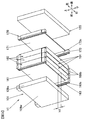
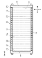
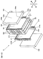
- FIG. 1 is an external perspective view of a power storage module 10 according to the first embodiment of the present invention
- FIG. 2 is an exploded perspective view showing the configuration of the power storage module 10.
- the power storage module 10 includes a cooling structure 190 and a power storage block 100.
- the power storage block 100 includes an element stack 11 in which a plurality of single cells 101 are stacked, an integrated mechanism that integrates the element stack 11, and a pressing device that presses the element stack 11 toward the cooling structure 190.
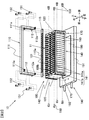
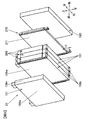
- FIG. 3 is an exploded perspective view showing the configuration of the element stack 11, and shows a part of the element stack 11.
- the element stack 11 includes a plurality of unit cells 101 and a plurality of battery holders 160 and 170.
- Each unit cell 101 has a flat rectangular parallelepiped shape and includes a pair of wide side plates 109w.
- the plurality of unit cells 101 constituting the element stack 11 are stacked so that the wide side plates 109w of the adjacent unit cells 101 face each other.
- adjacent unit cells 101 are arranged with their directions reversed so that the positions of the positive terminal 104 and the negative terminal 105 provided on the battery cover 108 are reversed.
- each adjacent unit cell 101 is electrically connected by a bus bar which is a metal plate-like conductive member. That is, the plurality of single cells 101 constituting the power storage block 100 according to the present embodiment are electrically connected in series.
- a positive electrode terminal 104 of the unit cell 101 arranged at the front end and a negative electrode terminal 105 of the unit cell 101 arranged at the rear end are electrically connected in series or in parallel with other power storage modules by conductive members. It is connected or connected to a power extraction wiring by a conductive member.
- FIG. 4 is a perspective view showing the unit cell 101.
- the unit cell 101 includes a rectangular battery container including a battery can 109 and a battery lid 108.
- the material of the battery can 109 and the battery lid 108 is, for example, aluminum or an aluminum alloy.
- the battery can 109 has a rectangular box shape having an opening 109a at one end.
- the battery lid 108 has a rectangular flat plate shape and is laser-welded so as to close the opening 109 a of the battery can 109. That is, the battery lid 108 seals the battery can 109.
- the rectangular battery container composed of the battery lid 108 and the battery can 109 has a hollow rectangular parallelepiped shape.
- the battery container has a pair of wide side plates 109w each having a surface (wide surface) having the largest area among the side surfaces constituting the battery container, and has a surface having the smallest area among the side surfaces constituting the battery container.
- the pair of narrow side plates 109n face each other, and the battery lid 108 and the bottom plate 109b of the battery can 109 face each other.
- the battery lid 108 is provided with a positive terminal 104 and a negative terminal 105.
- a charge / discharge element (not shown) is housed inside the battery container in a state of being covered by an insulating case (not shown).
- a positive electrode of a charge / discharge element (not shown) is connected to the positive terminal 104, and a negative electrode of the charge / discharge element is connected to the negative terminal 105. For this reason, electric power is supplied to the external device via the positive electrode terminal 104 and the negative electrode terminal 105, or external generated power is supplied to the charge / discharge element via the positive electrode terminal 104 and the negative electrode terminal 105 to be charged.
- the battery lid 108 is provided with a liquid injection hole for injecting an electrolyte into the battery container.
- the liquid injection hole is sealed with a liquid injection plug 108a after the injection of the electrolytic solution.
- the electrolytic solution for example, a non-aqueous electrolytic solution in which a lithium salt such as lithium hexafluorophosphate (LiPF6) is dissolved in a carbonic acid ester-based organic solvent such as ethylene carbonate can be used.
- the battery cover 108 is provided with a gas discharge valve 108b.
- the gas discharge valve 108b is formed by partially thinning the battery lid 108 by press working.
- the gas discharge valve 108b is cleaved when the unit cell 101 generates heat due to abnormalities such as overcharging and the pressure inside the battery container rises and reaches a predetermined pressure, and discharges the gas from the inside. This reduces the pressure in the battery container.
- the plurality of single cells 101 are stacked in the front-rear direction via the battery holders 160 and 170 to form the element stack 11.
- the material of the battery holders 160 and 170 is a resin having insulating properties and heat resistance, such as engineering plastics such as polybutylene terephthalate (PBT) and polycarbonate (PC), rubber, and the like.
- the battery holders 160 and 170 are an intermediate holder 160 disposed between adjacent unit cells 101, a unit cell 101 disposed at the front end and the end plate 120, and a unit cell 101 disposed at the rear end. And an end holder 170 disposed between the end plate 120 and the end plate 120.
- the material of the end plate 120 is a metal such as aluminum or an aluminum alloy. Since the intermediate holder 160 is interposed between the unit cells 101, insulation between the adjacent unit cells 101 is ensured. Since the end holder 170 is interposed between the end plate 120 and the unit cell 101, insulation between the end plate 120 and the unit cell 101 is ensured.
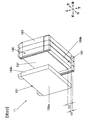
- FIG. 5 is a perspective view showing the intermediate holder 160.
- the intermediate holder 160 includes a wide surface contact portion 161 and a pair of connecting portions 163 provided at both ends of the wide surface contact portion 161 in the left-right direction.
- the wide surface contact portion 161 has a rectangular flat plate shape, and is disposed between adjacent unit cells 101 as shown in FIG. As shown in FIGS. 3 and 5, the wide surface abutting portion 161 abuts the front surface of the wide side plate 109 w on the rear side of the unit cell 101 in front of the intermediate holder 160. The rear surface of the wide surface contact portion 161 is in contact with the front wide side plate 109 w of the unit cell 101 behind the intermediate holder 160.
- the connecting portion 163 has a substantially rectangular parallelepiped shape with the vertical direction as the longitudinal direction.
- the right connecting portion 163 has a fitting convex portion 163a extending in the vertical direction on the front surface and a fitting concave portion 163b extending in the vertical direction on the rear surface.
- the left connecting portion 163 is provided with a fitting concave portion 163b extending in the vertical direction on the front surface and a fitting convex portion 163a extending in the vertical direction on the rear surface.
- the fitting convex portion 163a is fitted into the fitting concave portion 163b of the adjacent intermediate holder 160 or the fitting concave portion 173b of the adjacent end holder 170 described later.
- the fitting recess 163b is fitted into the fitting projection 163a of the adjacent intermediate holder 160 or the fitting projection 173a of the adjacent end holder 170 described later.
- Inner side surfaces 163s facing each other in the pair of connecting portions 163 are divided into two in the front-rear direction by the wide surface contact portions 161, respectively.
- the front inner surface 163 s is in contact with the narrow side plate 109 n of the unit cell 101 in front of the intermediate holder 160.
- the rear inner surface 163 s is in contact with the narrow side plate 109 n of the unit cell 101 behind the intermediate holder 160.
- the outer surface of the pair of connecting portions 163 is provided with a convex portion 167a that protrudes left and right outward.
- the protrusion 167a is fitted into an opening 143 of the side frame 140 described later.
- the convex portion 167a is provided at the center in the vertical direction, and a contact surface portion 167b that contacts a side plate 141 of the side frame 140 described later is provided on each of the both sides in the vertical direction of the convex portion 167a.
- a rectangular notch 161c is formed in the lower portion of the wide surface contact portion 161.
- the lower end portion of the connecting portion 163 projects downward from the wide surface contact portion 161.
- the lower end surface of the connecting portion 163 is positioned below the lower end surface of the wide surface contact portion 161 by a distance h1.
- the unit cell 101 is arranged such that the outer surface of the bottom plate 109b and the lower end surface of the connecting portion 163 are located on the same plane. That is, the outer surface of the bottom plate 109b of the unit cell 101 is located below the lower end surface of the wide surface contact portion 161 by a distance h1.
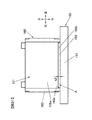
- FIG. 6 is a perspective view showing the end holder 170.
- the end holder 170 includes a wide surface contact portion 171 and a pair of connecting portions 173 provided at both ends of the wide surface contact portion 171 in the left-right direction.
- the end holder 170 is disposed between the unit cell 101 disposed at both ends in the front-rear direction, that is, the stacking direction of the element stack 11 and the end plate 120 described later.
- the end holder 170 located at the front end of the element laminate 11 and the end holder 170 located at the rear end of the element laminate 11 have the same shape. Therefore, hereinafter, the end holder 170 located at the rear end of the element stack 11 will be described as a representative.
- arrows indicating up, down, left, right, and front-back directions are described based on the posture of the end holder 170 located at the rear end of the element stack 11.
- the front surface of the wide surface contact portion 171 is in contact with the wide side plate 109 w on the rear side of the unit cell 101 in front of the end holder 170.
- the wide surface contact portion 171 is in contact with the end plate 120 at the rear surface.
- the connecting portion 173 has a substantially rectangular parallelepiped shape with the vertical direction as the longitudinal direction.
- a fitting projection 173a extending in the vertical direction is provided on the front surface of the right connecting portion 173, and a fitting recess 173b extending in the vertical direction is provided on the front surface of the left connecting portion 173.
- the end holder 170 positioned at the front end of the element stack 11 is disposed with its direction reversed by 180 degrees with respect to the end holder 170 shown in FIG.
- a fitting recess 173 b extending in the vertical direction is provided on the rear surface of the right connection portion 173, and on the rear surface of the left connection portion 173. Is provided with a fitting projection 173a extending in the vertical direction.
- the fitting convex portion 173a is fitted into the fitting concave portion 163b of the adjacent intermediate holder 160.
- the fitting recess 173b is fitted to the fitting protrusion 163a of the adjacent intermediate holder 160.
- the pair of connecting portions 173 are provided so as to protrude forward from the wide surface contact portion 171. Inner side surfaces 173 s of the pair of connecting portions 173 facing each other are in contact with the narrow side plate 109 n of the unit cell 101.
- the outer surface of the pair of connecting portions 173 is provided with a convex portion 177a that protrudes left and right outward.
- An opening 143 of the side frame 140 described later is fitted into the convex portion 177a.
- the convex portion 177a is provided at the center in the vertical direction, and a contact surface portion 177b that contacts a side plate 141 of the side frame 140 described later is provided on each of the both sides in the vertical direction of the convex portion 177a.
- a rectangular notch 171c is formed in the lower portion of the wide surface contact portion 171.
- the lower end portion of the connecting portion 173 protrudes downward from the wide surface contact portion 171.
- the lower end surface of the connecting portion 173 is positioned below the lower end surface of the wide surface contact portion 171 by a distance h1.
- the unit cell 101 is arranged such that the outer surface of the bottom plate 109b and the lower end surface of the connecting portion 173 are located on the same plane. That is, the outer surface of the bottom plate 109b of the unit cell 101 is located below the lower end surface of the wide surface contact portion 171 by a distance h1.
- the integration mechanism is configured to include a pair of end plates 120 and a pair of side frames 140, and binds a plurality of unit cells 101 stacked via battery holders 160 and 170.
- the end plate 120 has a rectangular flat plate shape and is formed to have approximately the same size as the unit cell 101.
- the pair of end plates 120 are respectively disposed in front of and behind the element stack 11, and sandwich the element stack 11 in the front-rear direction, that is, in the stacking direction.
- the pair of side frames 140 are disposed symmetrically on the left and right sides of the element stack 11.
- the side frame 140 includes a side plate 141 in which a rectangular flat plate is provided with a rectangular opening 143 and a bent portion that is bent 90 degrees in the same direction at both ends in the front-rear direction of the side plate 141. 142.
- the side plate 141 extends between a pair of side surface contact portions 141 a extending in parallel with each other between the front end plate 120 and the rear end plate 120, and between the upper end and the lower end of the element stack 11.
- a pair of engaging portions 141b extending in parallel with each other, and has a substantially rectangular shape when viewed from the left-right direction.
- the side frame 140 is manufactured by cutting a metal plate such as a stainless steel plate or a steel plate having a predetermined thickness into a predetermined width, punching the center into a rectangle, and bending the end portion.
- the convex portion 167a (see FIG. 5) of the intermediate holder 160 and the convex portion 177a (see FIG. 6) of the end holder 170 are formed in a rectangular parallelepiped as a whole when the coupling portions 163 and 173 are coupled and assembled as the element laminate 11.
- a convex portion 168 having a shape is formed.
- the opening 143 is provided corresponding to the outer shape of the convex portion 168.
- the upper and lower opening edges of the opening 143 are engaged with the upper and lower edges of the protrusion 168, and the front and rear opening edges of the opening 143 are engaged with the front and rear edges of the protrusion 177 a of the end holder 170. Match.
- the bent portion 142 is screwed to the end plate 120 with screws 150 while being in contact with the end plate 120.
- the battery holders 160 and 170 and the unit cell 101 sandwiched between the pair of end plates 120 are held in a compressed state.
- the positions of the plurality of intermediate holders 160 and the end holders 170 in the vertical and front-rear and left-right directions are restricted.
- the position of the unit cell 101 sandwiched between the battery holders 160 and 170 is restricted, and the position of the unit cell 101 sandwiched between the pair of connecting portions 163 and 173 of the battery holders 160 and 170 is restricted.
- the wide surface contact portions 161 and 171 are in contact with the wide side plate 109w of the unit cell 101, and the inner side surfaces 163s and 173s of the connecting portions 163 and 173 are in contact with the narrow side plate 109n of the unit cell 101. Therefore, the vertical position of the unit cell 101 is regulated by the frictional force on the contact surface.
- the method of fixing the side frame 140 to the end plate 120 using the screw 150 has been described.
- the side frame 140 is end-mounted using bolts, rivets, or the like, or by caulking or welding. It may be fixed to the plate 120.
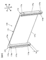
- the element stack 11 that is united by being united by the integration mechanism is assembled to the cooling structure 190.
- the cooling structure 190 includes a rectangular parallelepiped heat transfer plate 191, a cooling pipe 192 disposed inside the heat transfer plate 191, and a heat conductive sheet disposed on the heat transfer plate 191. 180.
- the heat transfer plate 191 and the cooling pipe 192 are made of a metal material having excellent thermal conductivity such as aluminum or an aluminum alloy.
- the cooling pipe 192 is a cylindrical pipe having a circular cross section, and forms a refrigerant flow path through which a cooling heat medium (hereinafter referred to as a refrigerant) such as an ethylene glycol aqueous solution flows.
- a refrigerant such as an ethylene glycol aqueous solution flows.
- the cooling pipe 192 has a U-shape as a whole, and a folded portion is provided near the rear end of the heat transfer plate 191 so that the refrigerant is U-turned once, and two straight pipe portions are provided. Are arranged along the front-rear direction. As shown in FIG. 2, a refrigerant inlet portion of the cooling pipe 192 and a refrigerant outlet portion are arranged in parallel at the front end of the heat transfer plate 191.
- the refrigerant flowing in the cooling pipe 192 is supplied to the refrigerant inlet from a heat exchange system including a pump, a radiator, a cooling fan, and the like.
- the refrigerant discharged from the refrigerant outlet is collected by the heat exchange system and cooled.
- the heat conductive sheet 180 has a thickness of about 2 mm and has good heat conductivity and good electrical insulation.
- a sheet having a thermal conductivity of about 1 to 5 W / m ⁇ K is preferably employed.
- the heat conductive sheet 180 has elasticity.
- a duct device 110 that guides the gas discharged from each gas discharge valve 108 b of each of the plurality of unit cells 101 to the outside of the vehicle is provided on the upper part of the element stack 11. .
- the duct device 110 is formed of a metal plate such as a stainless plate or a steel plate.
- the duct device 110 includes a gas guide portion 111 extending in the stacking direction of the element stack 11, that is, the front-rear direction.
- the gas guide 111 is a hollow rectangular tube member that forms a rectangular cross-section channel by an upper plate, a lower plate, and a pair of side plates that connect the upper plate and the lower plate.
- an opening for introducing gas is formed on the lower plate of the gas guide portion 111 at a position corresponding to the gas discharge valve 108b of each unit cell 101.
- a seal member 115 made of an insulating resin is disposed at a connection portion between the gas discharge valve 108 b and the gas guide portion 111.
- the seal member 115 extends in the front-rear direction from the front end plate 120 to the rear end plate 120.
- An opening 115 a is formed in the seal member 115 at a position corresponding to the gas discharge valve 108 b of each unit cell 101.
- the duct device 110 has a pair of legs 112 extending downward from the front end of the gas guide 111 and a pair of legs 112 extending downward from the rear end of the gas guide 111.
- Each leg 112 is provided with a leg attachment piece 112 a that is screwed to the heat transfer plate 191 with a screw 151.
- guide portion mounting pieces 111a that are screwed to the end plate 120 by screws 152 are provided.
- leg attachment piece 112 a when the leg attachment piece 112 a is screwed to the heat transfer plate 191 and the guide attachment piece 111 a is screwed to the upper surface of the end plate 120, it is integrated by the integration mechanism.
- the element stacked body 11 is pressed toward the heat conductive sheet 180 disposed on the heat transfer plate 191, that is, downward.
- Each unit cell 101 is sandwiched between the wide surface contact portions 161 and 171 of the battery holders 160 and 170 and sandwiched between the pair of connecting portions 163 and 173 of the battery holders 160 and 170. Therefore, the contact surface between the wide surface contact portions 161 and 171 and the wide side plate 109w of the unit cell 101, and the inner surfaces 163s and 173s of the connection units 163 and 173 of the battery holders 160 and 170 and the unit cell 101 are narrow. A frictional force acts on the contact surface with the side plate 109n.
- a downward pressing force acts on the battery lid 102 of each unit cell 101 from the gas guide 111 via the seal member 115.
- the duct device 110 presses the element stack 11 toward the heat conductive sheet 180 disposed on the heat transfer plate 191 (in other words, the heat transfer plate 191 is stacked on the element stack). It functions as a pressing device that presses toward the body 11.
- the duct device 110 as a pressing device elastically deforms the heat conductive sheet 180 sandwiched between the element laminate 11 and the heat transfer plate 191 so as to compress a predetermined amount, and maintains the state.
- the heat conductive sheet 180 can be brought into close contact with both the heat transfer surface of the element laminate 11 and the heat transfer surface of the heat transfer plate 191, and heat exchange can be performed efficiently. .
- thermally connected means that a state in which heat can be transferred between two objects is formed by a thermally conductive solid material such as metal or resin. ing. Between two thermally connected objects, heat flows from a hot object to a cold object until thermal equilibrium is reached.
- the heat transfer plate 191 absorbs heat generated in the unit cell 101 by exchanging heat with each unit cell 101 via the heat conductive sheet 180, that is, the unit cell 101 is cooled, and the temperature increase of the unit cell 101 is suppressed. To do.
- the heat transferred to the heat transfer plate 191 is transferred to the refrigerant through the cooling pipe 192 and is collected by the heat exchange system by the refrigerant.
- the duct device 110 When the element stack 11 is pressed against the heat conductive sheet 180 on the heat transfer plate 191 by the duct device 110, a compression reaction force acts on the duct device 110 via the element stack 11 according to the amount of compression of the heat conductive sheet 180. To do. For this reason, the thickness, shape, dimension, and material of the duct device 110 are set so as to ensure rigidity that can withstand the compression reaction force. If the reaction force acting on the duct device 110 can be reduced, the weight of the duct device 110 can be reduced.
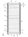
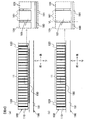
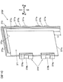
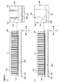
- FIG. 7 is a view of the power storage block 100 and the heat conductive sheet 180 as viewed from below. That is, FIG. 7 is a view in which the heat transfer plate 191 is omitted from the view of the power storage module 10 as viewed from below.
- FIG. 7 shows the heat conductive sheet 180 in a state where the element stack 11 is pressed downward by the duct device 110 and the heat conductive sheet 180 is sandwiched between the element stack 11 and the heat transfer plate 191 and compressed by a predetermined amount. ing.
- the heat conductive sheet 180 is a rectangular sheet, the dimension in the front-rear direction is substantially the same as the dimension in the front-rear direction of the element laminate 11, and the dimension in the left-right direction is larger than the dimension in the left-right direction of the element laminate 11. Slightly small.
- the amount of compression of the heat conductive sheet 180 needs to be managed within a range where permanent deformation does not occur in the heat conductive sheet 180.
- the amount of compression of the heat conductive sheet 180 is set to about 0.2 mm to 0.4 mm in consideration of the dimensional variation of each unit cell 101 pressed against the heat conductive sheet 180.
- FIG. 8A is a diagram illustrating a state before the power storage block 100 and the cooling structure 190 are thermally connected
- FIG. 8B is a diagram illustrating a state where the power storage block 100 and the cooling structure 190 are thermally connected. It is a figure which shows the state after connecting.
- FIG. 8 schematically shows a cross section of the power storage module 10 as viewed from the left, and also shows a partially enlarged view.
- the heat conductive sheet 180 When the element stack 11 is pressed against the heat conductive sheet 180, the heat conductive sheet 180 is compressed in the vertical direction (that is, the thickness direction) and expanded in the left-right front-rear direction. Further, as shown in the partially enlarged view of FIG. 8B, the heat conductive sheet 180 is deformed so that part of the heat conductive sheet 180 escapes into the gap between the adjacent unit cells 101.
- the thickness of the heat conductive sheet 180 before compression deformation is ts1
- the protrusion length h1 of the outer surface of the bottom plate 109b of the unit cell 101 with respect to the lower end surface of the wide surface contact portion 161 is the thickness of the heat conductive sheet 180.
- the heat conductive sheet 180 is compressed in a state of being disposed over the entire lower surface of the element laminate 11.
- the lower end surface of the wide surface contact portion 161 of the intermediate holder 160 is disposed to face the heat conductive sheet 180. That is, as shown in the partially enlarged view of FIG. 8B, the wide surface contact portion 161 and the heat conductive sheet 180 are arranged on a virtual straight line VL extending in a predetermined vertical direction.
- the lower end surface of the wide surface contact portion 171 of the end holder 170 is disposed to face the heat conductive sheet 180. That is, the wide surface contact portion 171 and the heat conductive sheet 180 are arranged on a virtual straight line extending in the vertical direction.
- the wide surface contact portions 161 and 171 are arranged to face each other on the heat conductive sheet 180, but notches 161 c and 171 c are provided below the wide surface contact portions 161 and 171. Therefore, when the element stack 11 is pressed against the heat conductive sheet 180, the heat conductive sheet 180 does not contact the lower end surfaces of the wide surface contact portions 161 and 171. As a result, only the bottom plate 109 b of the battery can 109 of the unit cell 101 can be brought into close contact with the heat conductive sheet 180 as the heat transfer surface of the element stack 11.
- the effect of reducing the compression reaction force was verified by comparing the case where the outer surface of the bottom plate 109b of the battery can 109 and the lower end surfaces of the wide surface contact portions 161 and 171 are on the same plane as a comparative example.
- the contact area between the heat conductive sheet 180 and the element laminate 11 can be reduced as compared with the comparative example because the wide surface contact portions 161 and 171 do not contact the heat conductive sheet 180. That is, the force per unit area of the bottom plate 109b of the unit cell 101 can be increased.
- the pressing force when the heat conductive sheet 180 was compressed at the same compression rate (for example, 40%) was compared.
- the pressing force (load) necessary to compress the heat conductive sheet 180 at a compression rate of 40% is Fa
- the pressing force (load) is Fb
- Fa / Fb is about 0.8. That is, according to the present embodiment, the compression reaction force accompanying the compressive deformation of the heat conductive sheet 180 can be reduced by about 20% compared to the case where the wide surface contact portions 161 and 171 are in contact with the heat conductive sheet 180. I knew it was possible.
- the unit cells 101 in order to bring all of the plurality of unit cells 101 constituting the element stack 11 into close contact with the heat conductive sheet 180, it is necessary to apply a pressing force in consideration of variation in the size of each unit cell 101.
- the compression reaction force can be reduced. Therefore, even if there is a variation in the dimensions of the unit cells 101, the unit cells 101 can be stably passed through the heat conductive sheet 180.
- the heat transfer plate 191 can be thermally connected.
- the element stack 11 is disposed between the adjacent unit cells 101 and the intermediate holder 160 that contacts the wide side plate 109w of the unit cell 101, and the unit cell 101. And an end holder 170 disposed between the end plate 120 and abutting against the wide side plate 109w of the unit cell 101.
- the outer surface of the bottom plate 109b of the unit cell 101, that is, the heat transfer surface of the unit cell 101 protrudes toward the heat transfer plate 191 side from the end surfaces of the wide surface contact portions 161 and 171 on the heat transfer plate 191 side.
- one surface of the battery container of the unit cell 101 is in close contact with the heat conductive sheet 180, and the wide surface contact portions 161 and 171 of the battery holders 160 and 170 are not in contact with the heat conductive sheet 180. ing.
- the compression reaction force which acts on the element laminated body 11 from the heat conductive sheet 180 can be made small. That is, the compression reaction force of the heat conductive sheet 180 acting on the duct device 110 as the pressing device can be reduced.
- the structure of the duct device 110 and the integration mechanism can be simplified, and the power storage module 10 can be reduced in weight and cost.
- it can prevent that the position shift of the single cell 101 arises by the frictional force in the contact surface of the single cell 101 and the battery holder 160,170.
- FIGS. A second embodiment of the present invention will be described with reference to FIGS.
- the same or corresponding parts as those in the first embodiment are denoted by the same reference numerals, and description thereof is omitted.
- differences from the first embodiment will be described in detail.
- FIG. 9 is a view similar to FIG. 3, and is an exploded perspective view showing the configuration of the element stack 21 of the power storage module according to the second embodiment of the present invention.
- FIG. 10 is a perspective view showing an intermediate holder 260 constituting the element laminate 21 of FIG. In FIG. 10, the intermediate holder 260 positioned at the right end of the element stack 21 is illustrated, and a part of the unit cell 101 that contacts the intermediate holder 260 is indicated by a two-dot chain line.
- FIG. 11 is a perspective view showing the end holder 170.
- the intermediate holder 160 includes a pair of connecting portions 163 and a wide surface contact portion 161 provided between the pair of connecting portions 163 (see FIG. 5).
- the intermediate holder 260 is not provided with a wide surface contact portion that contacts the wide side plate 109 w of the unit cell 101.
- the insulating film (not shown) which has insulation is adhering to the outer surface of the battery container of the single cell 101, and the adjacent single cells 101 contact each other via an insulating film. Yes.
- the intermediate holder 260 has a substantially rectangular parallelepiped shape with the vertical direction as the longitudinal direction, and a pair of intermediate holders 260 on the left and right of each unit cell 101 so as to contact the narrow side plate 109 n of the unit cell 101. Be placed.
- the intermediate holder 260 is provided with a fitting convex portion 163a extending in the vertical direction on one side in the front-rear direction, and a fitting concave portion 163b extending in the vertical direction on the other side in the front-rear direction.
- the pair of left and right intermediate holders 260 have the same shape.
- the pair of left and right intermediate holders 260 are arranged with their directions reversed by 180 degrees.
- the right intermediate holder 260 is provided with a fitting convex portion 163a on the front side and a fitting concave portion 163b on the rear side.
- the left intermediate holder 260 is provided with a fitting recess 163b on the front side and a fitting projection 163a on the rear side.
- the fitting projection 163a is fitted into the fitting recess 163b of the adjacent intermediate holder 260 or the fitting recess 273b of the adjacent end holder 270.
- the fitting concave portion 163b is fitted into the fitting convex portion 163a of the adjacent intermediate holder 260 or the fitting convex portion 273a of the adjacent end holder 270.
- a convex portion 167a is provided on the outer side surface of each of the pair of intermediate holders 260 so as to protrude left and right.
- the opening 143 of the side frame 140 is fitted into the convex portion 167a.
- the convex portion 167a is provided at the center in the vertical direction, and a contact surface portion 167b that contacts a side plate 141 of the side frame 140 described later is provided on each of the both sides in the vertical direction of the convex portion 167a.
- the end holder 270 includes a wide surface abutting portion 271 and a pair of connecting portions 273 provided at both ends of the wide surface abutting portion 271 in the left-right direction.
- the end holder 270 has a substantially rectangular flat plate shape, and is disposed between the unit cell 101 and the end plate 120 disposed at both ends in the front-rear direction, that is, in the stacking direction of the element stack 21 as shown in FIG. .
- the end holder 270 positioned at the front end of the element stack 21 and the end holder 270 positioned at the rear end of the element stack 21 have the same shape. Therefore, hereinafter, the end holder 270 located at the rear end of the element stack 21 will be described as a representative.
- arrows indicating up / down / left / right and front / rear directions are shown based on the posture of the end holder 270 located at the rear end of the element stack 21.
- the front surface of the wide surface contact portion 271 contacts the wide side plate 109 w on the rear side of the unit cell 101 in front of the end holder 270.
- the wide surface contact portion 271 is in contact with the end plate 120 of the end holder 270 at the rear surface.
- a fitting convex portion 273 a extending in the vertical direction is provided on the front surface of the right connecting portion 273, and a fitting extending in the vertical direction is provided on the front surface of the left connecting portion 273.
- a recess 273b is provided.
- the end holder 270 located at the front end of the element stack 21 is arranged with its direction reversed by 180 degrees with respect to the end holder 270 shown in FIG. For this reason, in the end holder 270 located at the front end of the element stack 21, the rear surface of the right connecting portion 273 is provided with a fitting recess 273 b extending in the vertical direction, and the rear surface of the left connecting portion 273 is provided. Is provided with a fitting convex portion 273a extending in the vertical direction.
- the fitting convex part 273a is fitted into the fitting concave part 163b of the adjacent intermediate holder 260.
- the fitting recess 273b is fitted into the fitting protrusion 163a of the adjacent intermediate holder 260.
- the left and right side surfaces of the pair of connecting portions 273 are provided with convex portions 277a that protrude outward in the left and right directions.
- the opening 143 of the side frame 140 is fitted into the convex portion 277a.
- the convex portion 277a is provided at the center in the vertical direction, and the contact surface portion 277b that contacts the side plate 141 of the side frame 140 is provided on both sides of the convex portion 277a in the vertical direction.
- a rectangular notch 271c is formed in the lower part of the wide surface contact portion 271.
- the lower end portion of the connecting portion 273 protrudes downward from the wide surface contact portion 271.
- the lower end surface of the connecting portion 273 is positioned below the lower end surface of the wide surface contact portion 271 by a distance h1.
- the unit cell 101 is arranged so that the outer surface of the bottom plate 109b and the lower end surface of the connecting portion 273 are located on the same plane. That is, the outer surface of the bottom plate 109b of the unit cell 101 is located below the lower end surface of the wide surface contact portion 271 by a distance h1.
- FIG. 12 is a view similar to FIG. 7, and is a view of the power storage block 200 and the heat conductive sheet 180 as viewed from below.
- FIG. 13 is a view similar to FIG.
- FIG. 13A is a diagram illustrating a state before the power storage block 200 and the cooling structure 190 are thermally connected.
- FIG. 13B illustrates a state where the power storage block 200 and the cooling structure 190 are thermally connected. It is a figure which shows the state after connecting.
- the lower end surface of the wide surface contact portion 271 of the end holder 270 is disposed to face the heat conductive sheet 180.
- the intermediate holder 160 is not provided with a wide surface contact portion.
- the end holder 270 is provided with a notch 271c as in the first embodiment. For this reason, when the power storage block 200 and the cooling structure 190 are thermally connected, the wide surface contact portion 271 is prevented from contacting the heat conductive sheet 180.
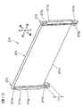
- FIG. 14 is an exploded perspective view showing a configuration of a power storage module 30 according to the third embodiment of the present invention
- FIG. 15 is a view of the power storage block 300 and the heat conductive sheet 180 as viewed from below.
- the outer surface of the bottom plate 109b of the unit cell 101 is a heat transfer surface that is in close contact with the heat conductive sheet 180, and the positive electrode terminal 104 and the negative electrode terminal 105 are provided on the battery lid 102 facing the bottom plate 109b. (See FIG. 1).
- the positive electrode terminal 104 and the negative electrode terminal 105 are arranged on the side surface of the element stack 31.
- FIG. 16 is a diagram similar to FIG. 3 and is an exploded perspective view showing the configuration of the element stack 31.
- FIG. 17 is a perspective view showing the intermediate holder 360
- FIGS. 18 and 19 are perspective views showing the rear end holder 370R and the front end holder 370F of the element stack 31.
- FIG. 17 is a perspective view showing the intermediate holder 360
- FIGS. 18 and 19 are perspective views showing the rear end holder 370R and the front end holder 370F of the element stack 31.
- the intermediate holder 360 includes a wide surface contact portion 361, a first connecting portion 363 provided along the upper end and right end of the wide surface contact portion 361, and the left end of the wide surface contact portion 361. And a pair of second connecting portions 364.
- the wide surface abutting portion 361 has a rectangular flat plate shape and is disposed between adjacent unit cells 101 as shown in FIG. As shown in FIG. 17, the front surface of the wide surface contact portion 361 is in contact with the wide side plate 109 w on the rear side of the unit cell 101 in front of the intermediate holder 360. The wide surface contact portion 361 is in contact with the front wide side plate 109 w of the unit cell 101 behind the intermediate holder 360 at the rear surface.
- a rectangular notch 361c is formed in the lower part of the wide surface contact part 361.
- the lower end portion of the first connecting portion 363 protrudes downward from the wide surface contact portion 361.
- the lower end surface of the first connecting portion 363 is positioned below the lower end surface of the wide surface contact portion 361 by a distance h1.
- the unit cell 101 is disposed such that the outer surface of the narrow side plate 109 n disposed on the lower side and the lower end surface of the first connecting portion 363 are located on the same plane. That is, the outer surface of the narrow side plate 109n on the lower side of the unit cell 101 is located below the lower end surface of the wide surface contact portion 361 by a distance h1.
- the first connecting portion 363 has a substantially L shape when viewed from the front-rear direction.
- a fitting recess 363b is provided on the front surface of the first connecting portion 363 from one end to the other end of the first connecting portion 363, and a fitting protrusion on the rear surface extending from one end to the other end of the first connecting portion 363. 363a is provided.
- the pair of second connecting portions 364 have the same shape, and each has a substantially rectangular parallelepiped shape.
- a fitting recess 364b extending in the vertical direction is provided on the front surface of the second connecting portion 364, and a fitting convex portion 364a extending in the vertical direction is provided on the rear surface of the second connecting portion 364.
- the fitting projection 363a is fitted into the fitting recess 363b of the adjacent intermediate holder 360 or the fitting recess 373b of the rear end holder 370R which will be described later.
- the fitting recess 363b is fitted into the fitting projection 363a of the adjacent intermediate holder 360 or the fitting projection 373a of the adjacent front end holder 370F which will be described later.
- the inner side surface 363s of the first connecting portion 363 is divided into two in the front-rear direction by the wide surface contact portion 361.
- the front inner surface 363 s is in contact with one of the pair of narrow side plates 109 n and the bottom plate 109 b in the unit cell 101 in front of the intermediate holder 360.
- the rear inner surface 363 s is in contact with one of the pair of narrow side plates 109 n and the bottom plate 109 b in the unit cell 101 behind the intermediate holder 360.
- the inner side surface 364s of the second connecting portion 364 is similarly divided into two in the front-rear direction by the wide surface contact portion 361.
- the front inner surface 364 s is in contact with the battery cover 108 of the unit cell 101 in front of the intermediate holder 360.
- the rear inner surface 364 s is in contact with the battery cover 108 of the unit cell 101 behind the intermediate holder 360.
- each convex portion 367 a protruding rightward is provided on the outer surface of the first connecting portion 363.
- a fitting concave portion 367b into which the side surface contact portion 141a of the side frame 140 is fitted is formed between the first convex portion 367a and the second convex portion 367a counted from above.
- a fitting concave portion 367b into which the side surface contact portion 141a of the side frame 140 is fitted is formed between the third convex portion 367a and the fourth convex portion 367a counted from above.
- the pair of second connecting portions 364 are arranged with a predetermined interval. Between the pair of second connecting portions 364, the gas discharge valve 108b of the battery lid 108 is disposed. Each second connecting portion 364 is provided with a fitting recess 368b into which the side contact portion 141a of the side frame 140 is fitted.
- the rear end holder 370 ⁇ / b> R disposed at the rear end of the element stack 31 and the front end holder 370 ⁇ / b> F disposed at the front end of the element stack 31 are arranged in the front-rear direction.
- a substantially plane-symmetric shape is formed with respect to the orthogonal plane.
- the rear end holder 370R will be described as a representative, and the front end holder 370F will be described only with respect to portions different from the rear end holder 370R.
- the rear end holder 370R includes a wide surface contact portion 371, a first connecting portion 373 provided along the upper end and right end of the wide surface contact portion 371, and a wide surface contact portion. And a pair of second connecting portions 374 provided at the left end of 371.
- the wide surface contact portion 371 has a rectangular flat plate shape, and is disposed between the unit cell 101 and the end plate 120 as shown in FIG. As shown in FIGS. 16 and 18, the wide surface abutting portion 371 abuts the front surface of the wide side plate 109 w on the rear side of the unit cell 101 in front of the rear end holder 370 ⁇ / b> R. The wide surface contact portion 371 is in contact with the end plate 120 at the rear surface.
- a rectangular notch 371c is formed in the lower portion of the wide surface contact portion 371.
- the lower end portion of the first connecting portion 373 protrudes below the wide surface contact portion 371.
- the lower end surface of the first connecting portion 373 is positioned below the lower end surface of the wide surface contact portion 371 by a distance h1.
- the unit cell 101 is arranged so that the outer surface of the narrow side plate 109n arranged on the lower side and the lower end surface of the first connecting portion 373 are on the same plane. That is, the outer surface of the narrow side plate 109n on the lower side of the unit cell 101 is located below the lower end surface of the wide surface contact portion 371 by a distance h1.
- the first connecting portion 373 has a substantially L shape when viewed from the front.
- a fitting recess 373 b is provided on the front surface of the first connecting portion 373 from one end to the other end of the first connecting portion 373.
- the fitting recess 373b is fitted into the fitting projection 363a of the adjacent intermediate holder 360.
- the pair of second connecting portions 374 have the same shape, and each has a substantially rectangular parallelepiped shape.
- a fitting recess 374b extending in the vertical direction is provided on the front surface of the second connecting portion 374.
- the fitting recess 374 b is fitted into the fitting protrusion 364 a of the adjacent intermediate holder 360.
- the first connecting portion 373 is provided so as to protrude forward from the wide surface contact portion 361.
- the inner side surface 373s of the first connecting portion 373 is in contact with one of the pair of narrow side plates 109n and the bottom plate 109b in the unit cell 101 in front of the intermediate holder 360.
- the second connecting portion 374 is similarly provided so as to protrude forward from the wide surface contact portion 371.
- the inner side surface 364 s of the second connecting portion 374 is in contact with the battery lid 108 of the unit cell 101 in front of the intermediate holder 360.
- a fitting concave portion 377b into which the side surface contact portion 141a of the side frame 140 is fitted is formed between the first convex portion 377a and the second convex portion 377a counted from above.
- a fitting concave portion 377b into which the side surface contact portion 141a of the side frame 140 is fitted is formed between the third convex portion 377a and the fourth convex portion 377a counted from above.
- the pair of second connecting portions 364 are arranged with a predetermined interval.
- a gas exhaust valve 108b of the battery lid 108 is disposed between the pair of second connection portions 374.
- Each second connecting portion 374 is provided with a fitting recess 378b into which the side contact portion 141a of the side frame 140 is fitted.
- the front end holder 370F is substantially symmetrical with the rear end holder 370R shown in FIG. 18 with respect to a plane orthogonal to the front-rear direction.
- the rear end holder 370R is provided with a fitting recess 373b and a fitting recess 374b in front of the first connecting portion 373 and the second connecting portion 374
- the front end holder 370F is In other words, fitting convex portions 373a and 374a are provided on the rear surfaces of the first connecting portion 373 and the second connecting portion 374.
- the element stack 31 is integrated by connecting the first connecting portions 363 and 373 and the second connecting portions 364 and 374.
- the side contact portion 141a of the left side frame 140 is fitted into the fitting recess 368b and the fitting recess 378b of the element stack 31 (see FIG. 14).
- the side contact portion 141a of the right side frame 140 is fitted into the fitting recess 367b and the fitting recess 377b of the element stack 31 (see FIG. 14).
- the second connecting portion 374 of the front end holder 370F is engaged with the front engaging portion 141b of the left side frame 140, and the rear end portion is connected to the rear engaging portion 141b of the left side frame 140.
- the second connecting part 374 of the part holder 370R is engaged.
- the convex portion 377a of the first connecting portion 373 of the front end holder 370F is engaged with the front engaging portion 141b of the right side frame 140, and the rear engaging portion of the left side frame 140 is engaged.
- the convex portion 377a of the first connecting portion 373 of the rear end holder 370R is engaged with the portion 141b.
- the bent portion 142 of the side frame 140 is screwed to the end plate 120 with screws 150.
- the element stack 31 is sandwiched between the pair of end plates 120 while being compressed by a predetermined amount in the stacking direction.
- the guide portion mounting piece 111 a is screwed to the end plate 120 with a screw 152
- the leg portion mounting piece 112 a is screwed to the heat transfer plate 191 with a screw 151.
- notch parts 361c and 371c are provided in the wide surface contact parts 361 and 371 of the battery holders 360, 370F, and 370R. For this reason, when the electrical storage block 300 and the cooling structure 190 are thermally connected, the wide surface contact portions 361 and 371 are prevented from coming into contact with the heat conductive sheet 180.
- the lower end surface of the connecting portion 163 of the intermediate holder 160 and the outer surface of the bottom plate 109b of the unit cell 101 are located on the same plane (see FIG. 3).
- the invention is not limited to this.
- the lower portion of the connecting portion 163 of the intermediate holder 160 may be protruded toward the heat transfer plate 191 side from the bottom plate 109 b of the unit cell 101.
- the lower end surface of the connecting portion 163 is positioned below the outer surface of the bottom plate 109b of the unit cell 101 by a distance h2.
- the lower end surface of the connecting portion 173 of the end holder 170 and the lower end surface of the end plate 120 are also lower than the outer surface of the bottom plate 109b of the unit cell 101 by a distance h2.
- the intermediate holder 160 will be described as a representative.
- FIG. 21 is a view of the intermediate holder 160 and the unit cell 101 of FIG. 20 as viewed from the front.
- the lower end surface of the connecting portion 163 is positioned below the outer surface of the bottom plate 109b.
- the lower end portion of the connecting portion 163 is a plate abutting portion that protrudes further toward the heat transfer plate 191 than the heat transfer surface of the unit cell 101.
- the lower end surface of the connecting portion 163 is directly on the surface of the heat transfer plate 191. Abut.
- the heat transfer plate 191 When the lower end surface of the connecting portion 163 contacts the heat transfer plate 191, the inner surface 163s of the connecting portion 163, the inner side surface 173s of the connecting portion 173, the outer surface of the bottom plate 109b of the unit cell 101, the heat transfer plate 191, A space A surrounded by the pair of end plates 120 is formed.
- the heat conductive sheet 180 is disposed in the space A.
- the distance h2 between the lower end surface of the connecting portion 163 and the outer surface of the bottom plate 109b of the unit cell 101 is set in consideration of the compressibility of the heat conductive sheet 180.
- ts1 the thickness of the heat conductive sheet 180 before compression
- it is necessary to satisfy 0 ⁇ h2 ⁇ ts1.
- the heat conductive sheet 180 is compressed until the lower end surface of the connecting portion 163 contacts the heat transfer plate 191.
- it becomes thickness ts2 h2 of the heat conductive sheet 180 after compression.
- the heat conductive sheet 180 When the heat conductive sheet 180 is compressed in the vertical direction (thickness direction), the heat conductive sheet 180 is deformed to expand in the front-rear and left-right directions. For this reason, the heat conduction sheet 180 having a size slightly smaller than the size of the space A in the front-rear and left-right direction is adopted so that the size in the front-rear and left-right direction after compression is accommodated in the space A.
- the thickness ts2 after compression of the heat conductive sheet 180 can be set to the distance h2. Although it is necessary to manage the compression ratio so that the heat conductive sheet 180 does not cause permanent deformation, according to this modification, the thickness ts2 after compression of the heat conductive sheet 180 is determined by the connecting portions 163 and 173 and the end plate. Since it is determined by the protrusion length h2 of 120, the compression rate can be easily managed. Furthermore, since the battery holders 160 and 170 and the end plate 120 are in contact with the heat transfer plate 191, the stability against vibrations and impacts acting on the power storage module 10 is improved as compared to the first embodiment. .
- the lower end surface of the intermediate holder 260 in order to bring the lower end surface of the intermediate holder 260 into contact with the heat transfer plate 191, the lower end surface of the intermediate holder 260 is set to the bottom plate 109b of the unit cell 101. You may make it position lower than the outer surface.
- the lower end surface of the connecting portion 273 of the end holder 270 in order to bring the lower end surface of the connecting portion 273 of the end holder 270 into contact with the heat transfer plate 191, the lower end surface of the connecting portion 273 of the end holder 270 is The unit cell 101 may be positioned below the outer surface of the bottom plate 109b.
- the lower end surface of the first connecting portion 363 of the intermediate holder 360 is positioned below the outer surface of the narrow side plate 109n of the unit cell 101. It may be.
- the first end of the end holders 370F and 370R is used in order to bring the lower end surface of the first connecting portion 373 of the end holders 370F and 370R into contact with the heat transfer plate 191.
- the lower end surface of the connecting portion 373 may be positioned below the outer surface of the narrow side plate 109n of the unit cell 101.
- the method of connecting the duct device 110 and the heat transfer plate 191 is not limited to the above-described embodiment.
- the end plate 120 may be fixed to the heat transfer plate 191 using a so-called L-shaped metal fitting 499 and a screw 498.
- two L-shaped metal fittings 499 are attached to each of the pair of end plates 120.
- the present invention is not limited to this.
- a strip-shaped heat conductive sheet 580 corresponding to the bottom plate 109b may be arranged for each unit cell 101 as shown in FIG.
- the wide surface contact portion 161 of the intermediate holder 160 and the wide surface contact portion 171 of the end holder 170 do not contact the heat conduction sheet 580, and only the bottom plate 109b of the unit cell 101 is attached.
- the heat conductive sheet 580 can be brought into intimate contact, and the compression reaction force can be reduced.
- the heat conductive sheet 180 has been described as an example having good thermal conductivity and good electrical insulation, but the present invention is not limited to this.
- a heat conductive sheet having good heat conductivity and an insulating sheet having good electrical insulation may be used in an overlapping manner.
- the element stacks 11, 21, 31 are composed of the plurality of single cells 101 and the battery holders 160, 170, 260, 270, 360, 370 F, 370 R, but the present invention is not limited to this.
- the present invention in order to adjust the dimension of the element stack 11 in the longitudinal direction (stacking direction), it is between the end holder 170 and the unit cell 101 or between the end holder 170 and the end plate.
- a spacer may be disposed between the spacers 120 and 120.
- a spacer may be arranged.
- the end holders 170, 270, 370 F, and 370 R can be omitted by providing an insulating property to the end plate 120 or the battery container of the unit cell 101.
- the heat conductive sheet 180 can be used in combination with an insulating heat conductive gel such as silicon oil.
- an insulating heat conductive gel such as silicon oil.
- the heat transfer surfaces of the element laminates 11, 21, 31 and the surface of the heat transfer plate 191 can be brought into close contact with the heat conductive sheet 180 in a more stable surface contact state.
- the heat conductive gel plays a role of absorbing variations in the dimensions of the battery container of the unit cell 101. For this reason, the compression amount of the heat conductive sheet 180 can be made small compared with the case where the heat conductive sheet 180 is used alone.
- the cooling pipe 192 is arranged on the heat transfer plate 191
- the present invention is not limited to this.
- a heating pipe that circulates a heat medium for heating the heat transfer plate 191 may be disposed on the heat transfer plate 191.
- the heating tube in a power storage module used in a cold district or winter, it can be warmed to a temperature at which the performance of the power storage module can be sufficiently exhibited before use.
- the temperature can be adjusted in a temperature range suitable for the unit cell 101.
- the power storage module 10 incorporated in a power storage device mounted on a hybrid electric vehicle or a pure electric vehicle has been described, but the present invention is not limited to this.
- Other electric vehicles for example, railway vehicles such as hybrid trains, passenger cars such as buses, cargo vehicles such as trucks, industrial vehicles such as turret vehicles and battery-powered forklift trucks, construction machines such as cranes and excavators
- the present invention may be applied to power storage modules that can be used in power storage devices such as unmanned mobile vehicles and golf carts.
- the present invention may be applied to a power storage module incorporated in a stationary power storage device.
- the present invention can also be applied as a power source for medical devices, power storage systems, elevators, and the like.
- a power storage system in which a power storage element is charged and stored with electric power generated by solar power generation or wind power generation. It can be used as a power storage system that charges and stores a power storage element by using nighttime midnight power. It can also be used as a power storage system that can be used outside the ground, such as a space station, spacecraft, or space base.
- the present invention can also be applied to other secondary batteries such as a nickel metal hydride battery. Furthermore, the present invention can be applied to a power storage module using an electric double layer capacitor or a lithium ion capacitor as a power storage element.
- the present invention is not limited to the above-described embodiments, and other forms conceivable within the scope of the technical idea of the present invention are also included in the scope of the present invention. .
Landscapes
- Engineering & Computer Science (AREA)
- Manufacturing & Machinery (AREA)
- Chemical & Material Sciences (AREA)
- Chemical Kinetics & Catalysis (AREA)
- Electrochemistry (AREA)
- General Chemical & Material Sciences (AREA)
- Secondary Cells (AREA)
- Battery Mounting, Suspending (AREA)
- Electric Double-Layer Capacitors Or The Like (AREA)
Priority Applications (5)
| Application Number | Priority Date | Filing Date | Title |
|---|---|---|---|
| CN201480032080.7A CN105264688B (zh) | 2013-06-06 | 2014-05-28 | 蓄电部件和蓄电组件 |
| EP14807786.0A EP3007249B1 (de) | 2013-06-06 | 2014-05-28 | Elektrizitätsspeicherblock und elektrizitätsspeichermodul |
| US14/895,665 US9887440B2 (en) | 2013-06-06 | 2014-05-28 | Electricity storage block and electricity storage module |
| EP18171859.4A EP3407403B1 (de) | 2013-06-06 | 2014-05-28 | Elektrizitätsspeicherblock und elektrizitätsspeichermodul |
| US15/854,297 US11670814B2 (en) | 2013-06-06 | 2017-12-26 | Electricity storage block and electricity storage module |
Applications Claiming Priority (3)
| Application Number | Priority Date | Filing Date | Title |
|---|---|---|---|
| JP2013119729A JP6174381B2 (ja) | 2013-06-06 | 2013-06-06 | 蓄電ブロックおよび蓄電モジュール |
| JP2013-119729 | 2013-06-06 | ||
| JP2017132714A JP6348641B2 (ja) | 2013-06-06 | 2017-07-06 | 蓄電モジュール、電池モジュールの製造方法 |
Related Child Applications (2)
| Application Number | Title | Priority Date | Filing Date |
|---|---|---|---|
| US14/895,665 A-371-Of-International US9887440B2 (en) | 2013-06-06 | 2014-05-28 | Electricity storage block and electricity storage module |
| US15/854,297 Continuation US11670814B2 (en) | 2013-06-06 | 2017-12-26 | Electricity storage block and electricity storage module |
Publications (1)
| Publication Number | Publication Date |
|---|---|
| WO2014196422A1 true WO2014196422A1 (ja) | 2014-12-11 |
Family
ID=61661276
Family Applications (1)
| Application Number | Title | Priority Date | Filing Date |
|---|---|---|---|
| PCT/JP2014/064048 WO2014196422A1 (ja) | 2013-06-06 | 2014-05-28 | 蓄電ブロックおよび蓄電モジュール |
Country Status (5)
| Country | Link |
|---|---|
| US (2) | US9887440B2 (de) |
| EP (2) | EP3007249B1 (de) |
| JP (2) | JP6174381B2 (de) |
| CN (2) | CN105264688B (de) |
| WO (1) | WO2014196422A1 (de) |
Cited By (3)
| Publication number | Priority date | Publication date | Assignee | Title |
|---|---|---|---|---|
| CN107534196A (zh) * | 2015-09-24 | 2018-01-02 | 株式会社Lg化学 | 电池模块 |
| CN111969137A (zh) * | 2019-05-20 | 2020-11-20 | 奥迪股份公司 | 用于将导热介质引入到电池模块和冷却底板之间的方法、注射系统和电池模块 |
| WO2021187114A1 (ja) * | 2020-03-18 | 2021-09-23 | 株式会社Gsユアサ | 蓄電装置 |
Families Citing this family (36)
| Publication number | Priority date | Publication date | Assignee | Title |
|---|---|---|---|---|
| JP5835315B2 (ja) * | 2013-12-26 | 2015-12-24 | 株式会社豊田自動織機 | 蓄電モジュールユニット及び蓄電モジュールユニットの製造方法 |
| CN107078249B (zh) * | 2014-11-10 | 2020-04-17 | 株式会社丰田自动织机 | 电池模块 |
| KR101806415B1 (ko) * | 2014-12-19 | 2017-12-07 | 주식회사 엘지화학 | 냉각효율이 향상된 이차전지 셀 및 이를 포함하는 모듈형 전지 |
| JP6609989B2 (ja) * | 2015-05-20 | 2019-11-27 | 株式会社豊田自動織機 | 電池モジュール |
| US10199621B2 (en) * | 2015-06-11 | 2019-02-05 | Ford Global Technologies, Llc | Battery cell spacer for establishing dielectric barriers within a battery assembly |
| US10084217B2 (en) * | 2016-02-16 | 2018-09-25 | Lg Chem, Ltd. | Battery system |
| KR102072764B1 (ko) * | 2016-03-03 | 2020-02-03 | 주식회사 엘지화학 | 배터리 모듈 및 이를 포함하는 배터리 팩, 자동차 |
| JP6615714B2 (ja) * | 2016-07-29 | 2019-12-04 | 本田技研工業株式会社 | 電気自動車用のバッテリパック |
| DE102016009212A1 (de) * | 2016-08-01 | 2018-02-01 | Audi Ag | Batteriemodul und Batterie |
| JP6957478B2 (ja) * | 2016-08-29 | 2021-11-02 | 三洋電機株式会社 | 電源装置 |
| US11233267B2 (en) * | 2017-03-07 | 2022-01-25 | Panasonic Intellectual Property Management Co., Ltd. | Separator, battery module and battery module production method |
| JP6928826B2 (ja) * | 2017-04-12 | 2021-09-01 | パナソニックIpマネジメント株式会社 | 電池モジュールおよび蓄電ユニット |
| WO2019039116A1 (ja) * | 2017-08-22 | 2019-02-28 | 日立オートモティブシステムズ株式会社 | 電池パック |
| CN109599632B (zh) * | 2017-09-30 | 2020-11-20 | 比亚迪股份有限公司 | 车载电池的温度调节方法和温度调节系统 |
| JP6965717B2 (ja) * | 2017-12-13 | 2021-11-10 | トヨタ自動車株式会社 | 電池パックの製造方法 |
| JP6923007B2 (ja) * | 2018-01-31 | 2021-08-18 | 株式会社豊田自動織機 | 蓄電装置 |
| JP7207398B2 (ja) * | 2018-03-23 | 2023-01-18 | 株式会社Gsユアサ | 蓄電装置 |
| CN110323371B (zh) * | 2018-03-29 | 2021-02-12 | 宁德时代新能源科技股份有限公司 | 电池模组 |
| JP7310095B2 (ja) * | 2018-03-30 | 2023-07-19 | トヨタ自動車株式会社 | 電池温度調節装置 |
| FR3062521B1 (fr) * | 2018-04-10 | 2023-09-08 | Sogefi Air & Cooling | Unite de batterie avec des moyens de regulation de la temperature integres au boitier |
| JP2020030970A (ja) * | 2018-08-22 | 2020-02-27 | 株式会社デンソー | 電池モジュール |
| CN112272886B (zh) * | 2018-09-26 | 2022-11-08 | 日本汽车能源株式会社 | 电池组装体 |
| CN113196547B (zh) * | 2018-12-20 | 2023-05-12 | 株式会社丰田自动织机 | 蓄电装置 |
| CN209401679U (zh) * | 2018-12-29 | 2019-09-17 | 宁德时代新能源科技股份有限公司 | 电池箱 |
| HUE060771T2 (hu) | 2019-01-09 | 2023-04-28 | Byd Co Ltd | Akkumulátor csomag, jármû és energiatároló eszköz |
| JP7151493B2 (ja) * | 2019-01-15 | 2022-10-12 | トヨタ自動車株式会社 | 電池装置 |
| KR102640879B1 (ko) | 2019-02-08 | 2024-02-23 | 에스케이온 주식회사 | 배터리 모듈 및 이의 제조방법 |
| US11505143B2 (en) * | 2019-02-27 | 2022-11-22 | Ford Global Technologies, Llc | Supercapacitor mounting assemblies and vehicle mounting locations |
| JP7354265B2 (ja) * | 2019-06-12 | 2023-10-02 | エルジー エナジー ソリューション リミテッド | 電池モジュール、その製造方法および電池パック |
| JP7267129B2 (ja) * | 2019-07-10 | 2023-05-01 | 本田技研工業株式会社 | 蓄電モジュール |
| WO2021024772A1 (ja) * | 2019-08-07 | 2021-02-11 | 三洋電機株式会社 | 電源装置及びこれを用いた電動車両並びに蓄電装置 |
| CN110994044B (zh) * | 2019-11-11 | 2022-06-24 | 安徽理士电源技术有限公司 | 带有保护结构的铅酸蓄电池 |
| JP7259721B2 (ja) * | 2019-12-02 | 2023-04-18 | トヨタ自動車株式会社 | 電池モジュール |
| JP7333001B2 (ja) * | 2019-12-26 | 2023-08-24 | トヨタ自動車株式会社 | 組電池および電池ホルダー |
| WO2021199596A1 (ja) * | 2020-03-31 | 2021-10-07 | 三洋電機株式会社 | 電源装置及びこれを備える車両並びに蓄電装置 |
| US11877423B2 (en) * | 2020-10-08 | 2024-01-16 | Toyota Motor Engineering And Manufacturing North America, Inc. | Battery thermal management with large area planar heat pipes |
Citations (4)
| Publication number | Priority date | Publication date | Assignee | Title |
|---|---|---|---|---|
| JP2011034775A (ja) | 2009-07-31 | 2011-02-17 | Sanyo Electric Co Ltd | 組電池の冷却構造、及び、バッテリーシステム |
| JP2011171029A (ja) * | 2010-02-17 | 2011-09-01 | Sanyo Electric Co Ltd | 電池モジュール |
| WO2012117681A1 (ja) * | 2011-02-28 | 2012-09-07 | 三洋電機株式会社 | 電池モジュールおよび電池モジュールの製造方法 |
| JP2012248339A (ja) * | 2011-05-25 | 2012-12-13 | Sanyo Electric Co Ltd | 電力用の電源装置及び電源装置を備える車両 |
Family Cites Families (13)
| Publication number | Priority date | Publication date | Assignee | Title |
|---|---|---|---|---|
| JP2002216731A (ja) * | 2001-01-23 | 2002-08-02 | Toyota Motor Corp | バッテリのガス排出構造 |
| JP5181327B2 (ja) * | 2007-10-25 | 2013-04-10 | 本田技研工業株式会社 | 蓄電装置 |
| JP2009135088A (ja) * | 2007-10-29 | 2009-06-18 | Panasonic Corp | 電池パックおよび電池搭載機器 |
| JP5334420B2 (ja) | 2008-01-16 | 2013-11-06 | 三洋電機株式会社 | バッテリシステム |
| JP2009301877A (ja) * | 2008-06-13 | 2009-12-24 | Toyoda Gosei Co Ltd | 組電池装置 |
| JP2010192207A (ja) * | 2009-02-17 | 2010-09-02 | Mitsubishi Heavy Ind Ltd | 電池用冷却装置及び組電池 |
| JP2010251019A (ja) * | 2009-04-13 | 2010-11-04 | Sanyo Electric Co Ltd | バッテリシステム |
| KR101084933B1 (ko) * | 2009-12-04 | 2011-11-17 | 삼성에스디아이 주식회사 | 이차 전지 모듈 및 이차 전지 모듈의 전지 스페이서 |
| CN103168387A (zh) | 2010-07-29 | 2013-06-19 | E4V公司 | 电池组冷却系统和包括这类系统的电池组 |
| JP5804323B2 (ja) * | 2011-01-07 | 2015-11-04 | 株式会社Gsユアサ | 蓄電素子及び蓄電装置 |
| US9859532B2 (en) * | 2011-03-31 | 2018-01-02 | Johnson Controls Technology Llc | Battery module and method incorporating exterior casing and liner |
| KR101199148B1 (ko) * | 2011-04-21 | 2012-11-09 | 에스비리모티브 주식회사 | 배터리 모듈 |
| WO2017169729A1 (ja) * | 2016-03-30 | 2017-10-05 | 三洋電機株式会社 | バッテリパック |
-
2013
- 2013-06-06 JP JP2013119729A patent/JP6174381B2/ja active Active
-
2014
- 2014-05-28 EP EP14807786.0A patent/EP3007249B1/de active Active
- 2014-05-28 CN CN201480032080.7A patent/CN105264688B/zh active Active
- 2014-05-28 WO PCT/JP2014/064048 patent/WO2014196422A1/ja active Application Filing
- 2014-05-28 US US14/895,665 patent/US9887440B2/en active Active
- 2014-05-28 EP EP18171859.4A patent/EP3407403B1/de active Active
- 2014-05-28 CN CN201710784618.5A patent/CN107681076B/zh active Active
-
2017
- 2017-07-06 JP JP2017132714A patent/JP6348641B2/ja active Active
- 2017-12-26 US US15/854,297 patent/US11670814B2/en active Active
Patent Citations (4)
| Publication number | Priority date | Publication date | Assignee | Title |
|---|---|---|---|---|
| JP2011034775A (ja) | 2009-07-31 | 2011-02-17 | Sanyo Electric Co Ltd | 組電池の冷却構造、及び、バッテリーシステム |
| JP2011171029A (ja) * | 2010-02-17 | 2011-09-01 | Sanyo Electric Co Ltd | 電池モジュール |
| WO2012117681A1 (ja) * | 2011-02-28 | 2012-09-07 | 三洋電機株式会社 | 電池モジュールおよび電池モジュールの製造方法 |
| JP2012248339A (ja) * | 2011-05-25 | 2012-12-13 | Sanyo Electric Co Ltd | 電力用の電源装置及び電源装置を備える車両 |
Non-Patent Citations (1)
| Title |
|---|
| See also references of EP3007249A4 |
Cited By (6)
| Publication number | Priority date | Publication date | Assignee | Title |
|---|---|---|---|---|
| CN107534196A (zh) * | 2015-09-24 | 2018-01-02 | 株式会社Lg化学 | 电池模块 |
| EP3343691A4 (de) * | 2015-09-24 | 2018-08-15 | LG Chem, Ltd. | Batteriemodul |
| US10658716B2 (en) | 2015-09-24 | 2020-05-19 | Lg Chem, Ltd. | Battery module |
| CN111969137A (zh) * | 2019-05-20 | 2020-11-20 | 奥迪股份公司 | 用于将导热介质引入到电池模块和冷却底板之间的方法、注射系统和电池模块 |
| CN111969137B (zh) * | 2019-05-20 | 2022-09-23 | 奥迪股份公司 | 用于将导热介质引入到电池模块和冷却底板之间的方法、注射系统和电池模块 |
| WO2021187114A1 (ja) * | 2020-03-18 | 2021-09-23 | 株式会社Gsユアサ | 蓄電装置 |
Also Published As
| Publication number | Publication date |
|---|---|
| CN105264688B (zh) | 2017-10-03 |
| US9887440B2 (en) | 2018-02-06 |
| EP3407403B1 (de) | 2024-03-20 |
| CN107681076B (zh) | 2020-12-08 |
| JP6174381B2 (ja) | 2017-08-02 |
| JP2017212214A (ja) | 2017-11-30 |
| JP2014238928A (ja) | 2014-12-18 |
| EP3407403A1 (de) | 2018-11-28 |
| US11670814B2 (en) | 2023-06-06 |
| US20180123199A1 (en) | 2018-05-03 |
| EP3007249B1 (de) | 2018-07-11 |
| EP3007249A4 (de) | 2017-02-01 |
| US20160141737A1 (en) | 2016-05-19 |
| EP3007249A1 (de) | 2016-04-13 |
| CN105264688A (zh) | 2016-01-20 |
| CN107681076A (zh) | 2018-02-09 |
| JP6348641B2 (ja) | 2018-06-27 |
Similar Documents
| Publication | Publication Date | Title |
|---|---|---|
| JP6348641B2 (ja) | 蓄電モジュール、電池モジュールの製造方法 | |
| JP6014752B2 (ja) | 安定性が向上した構造及び高い冷却効率性を有する電池モジュール | |
| EP2763214B1 (de) | Batteriemodul | |
| KR101130043B1 (ko) | 냉각 효율성이 향상된 전지모듈 | |
| KR101307992B1 (ko) | 높은 효율성의 냉각 구조를 포함하는 전지모듈 | |
| JP5734704B2 (ja) | 電源装置及び電源装置を備える車両 | |
| US9929385B2 (en) | Battery module of improved stability | |
| KR101431717B1 (ko) | 신규한 구조의 버스 바 | |
| KR101547814B1 (ko) | 간접 공냉 구조를 포함하는 전지모듈 | |
| CN102893449A (zh) | 具有新颖结构的冷却构件和包括该冷却构件的电池模块 | |
| KR20130004141A (ko) | 전원 장치 및 전원 장치를 구비하는 차량 | |
| JP2014513380A (ja) | エネルギー貯蔵装置 | |
| JP2009529218A (ja) | 電池モジュール | |
| KR20140039350A (ko) | 냉각 효율이 향상된 전지모듈 | |
| KR101658517B1 (ko) | 냉각 부재를 활용한 전지모듈 | |
| JP2015076188A (ja) | 電池モジュール | |
| JP2012094312A (ja) | 組電池、及び、セパレーター | |
| KR20140144784A (ko) | 간접 냉각 구조를 포함하는 전지모듈 | |
| WO2013038520A1 (ja) | 組電池 | |
| JP2014010952A (ja) | 蓄電装置 | |
| KR20240030990A (ko) | 배터리 팩 및 이를 포함하는 자동차 |
Legal Events
| Date | Code | Title | Description |
|---|---|---|---|
| WWE | Wipo information: entry into national phase |
Ref document number: 201480032080.7 Country of ref document: CN |
|
| 121 | Ep: the epo has been informed by wipo that ep was designated in this application |
Ref document number: 14807786 Country of ref document: EP Kind code of ref document: A1 |
|
| WWE | Wipo information: entry into national phase |
Ref document number: 2014807786 Country of ref document: EP |
|
| WWE | Wipo information: entry into national phase |
Ref document number: 14895665 Country of ref document: US |
|
| NENP | Non-entry into the national phase |
Ref country code: DE |