EP3407403B1 - Elektrizitätsspeicherblock und elektrizitätsspeichermodul - Google Patents
Elektrizitätsspeicherblock und elektrizitätsspeichermodul Download PDFInfo
- Publication number
- EP3407403B1 EP3407403B1 EP18171859.4A EP18171859A EP3407403B1 EP 3407403 B1 EP3407403 B1 EP 3407403B1 EP 18171859 A EP18171859 A EP 18171859A EP 3407403 B1 EP3407403 B1 EP 3407403B1
- Authority
- EP
- European Patent Office
- Prior art keywords
- electricity storage
- thermally
- conductive sheet
- battery
- abutment
- Prior art date
- Legal status (The legal status is an assumption and is not a legal conclusion. Google has not performed a legal analysis and makes no representation as to the accuracy of the status listed.)
- Active
Links
- 230000005611 electricity Effects 0.000 title claims description 97
- 238000003860 storage Methods 0.000 title claims description 97
- 238000003825 pressing Methods 0.000 claims description 12
- 230000006835 compression Effects 0.000 description 32
- 238000007906 compression Methods 0.000 description 32
- 238000001816 cooling Methods 0.000 description 31
- 239000007789 gas Substances 0.000 description 26
- 230000004048 modification Effects 0.000 description 13
- 238000012986 modification Methods 0.000 description 13
- 238000006243 chemical reaction Methods 0.000 description 12
- 239000003507 refrigerant Substances 0.000 description 11
- 238000010586 diagram Methods 0.000 description 9
- 230000010354 integration Effects 0.000 description 7
- 238000007599 discharging Methods 0.000 description 5
- 230000002349 favourable effect Effects 0.000 description 5
- 238000010438 heat treatment Methods 0.000 description 5
- 238000002347 injection Methods 0.000 description 5
- 239000007924 injection Substances 0.000 description 5
- 229910052751 metal Inorganic materials 0.000 description 5
- 239000002184 metal Substances 0.000 description 5
- HBBGRARXTFLTSG-UHFFFAOYSA-N Lithium ion Chemical compound [Li+] HBBGRARXTFLTSG-UHFFFAOYSA-N 0.000 description 4
- 230000000052 comparative effect Effects 0.000 description 4
- 239000008151 electrolyte solution Substances 0.000 description 4
- 238000009413 insulation Methods 0.000 description 4
- 239000007788 liquid Substances 0.000 description 4
- 229910001416 lithium ion Inorganic materials 0.000 description 4
- 239000000463 material Substances 0.000 description 4
- 230000001105 regulatory effect Effects 0.000 description 4
- 229910000838 Al alloy Inorganic materials 0.000 description 3
- LYCAIKOWRPUZTN-UHFFFAOYSA-N Ethylene glycol Chemical compound OCCO LYCAIKOWRPUZTN-UHFFFAOYSA-N 0.000 description 3
- 229910052782 aluminium Inorganic materials 0.000 description 3
- XAGFODPZIPBFFR-UHFFFAOYSA-N aluminium Chemical compound [Al] XAGFODPZIPBFFR-UHFFFAOYSA-N 0.000 description 3
- 239000011347 resin Substances 0.000 description 3
- 229920005989 resin Polymers 0.000 description 3
- 229910000831 Steel Inorganic materials 0.000 description 2
- 238000005452 bending Methods 0.000 description 2
- 239000003990 capacitor Substances 0.000 description 2
- -1 carbonate ester Chemical class 0.000 description 2
- 230000000694 effects Effects 0.000 description 2
- 239000001257 hydrogen Substances 0.000 description 2
- 229910052739 hydrogen Inorganic materials 0.000 description 2
- 238000000034 method Methods 0.000 description 2
- 229920001707 polybutylene terephthalate Polymers 0.000 description 2
- 239000000243 solution Substances 0.000 description 2
- 125000006850 spacer group Chemical group 0.000 description 2
- 239000010935 stainless steel Substances 0.000 description 2
- 229910001220 stainless steel Inorganic materials 0.000 description 2
- 239000010959 steel Substances 0.000 description 2
- KMTRUDSVKNLOMY-UHFFFAOYSA-N Ethylene carbonate Chemical compound O=C1OCCO1 KMTRUDSVKNLOMY-UHFFFAOYSA-N 0.000 description 1
- 229910001290 LiPF6 Inorganic materials 0.000 description 1
- XUIMIQQOPSSXEZ-UHFFFAOYSA-N Silicon Chemical compound [Si] XUIMIQQOPSSXEZ-UHFFFAOYSA-N 0.000 description 1
- USHGRFXQYJEHII-UHFFFAOYSA-M [O-]P(O)(O)=O.[Li+].F.F.F.F.F.F Chemical compound [O-]P(O)(O)=O.[Li+].F.F.F.F.F.F USHGRFXQYJEHII-UHFFFAOYSA-M 0.000 description 1
- 230000005856 abnormality Effects 0.000 description 1
- 230000015556 catabolic process Effects 0.000 description 1
- 238000010276 construction Methods 0.000 description 1
- 238000005520 cutting process Methods 0.000 description 1
- 230000003247 decreasing effect Effects 0.000 description 1
- 238000006731 degradation reaction Methods 0.000 description 1
- 230000001419 dependent effect Effects 0.000 description 1
- 229920006351 engineering plastic Polymers 0.000 description 1
- 229910003002 lithium salt Inorganic materials 0.000 description 1
- 159000000002 lithium salts Chemical class 0.000 description 1
- 239000007769 metal material Substances 0.000 description 1
- 239000003921 oil Substances 0.000 description 1
- 239000003960 organic solvent Substances 0.000 description 1
- 229920000515 polycarbonate Polymers 0.000 description 1
- 239000004417 polycarbonate Substances 0.000 description 1
- 238000004080 punching Methods 0.000 description 1
- 229910052710 silicon Inorganic materials 0.000 description 1
- 239000010703 silicon Substances 0.000 description 1
- 239000011343 solid material Substances 0.000 description 1
- 238000003466 welding Methods 0.000 description 1
Images


Classifications
-
- H—ELECTRICITY
- H01—ELECTRIC ELEMENTS
- H01M—PROCESSES OR MEANS, e.g. BATTERIES, FOR THE DIRECT CONVERSION OF CHEMICAL ENERGY INTO ELECTRICAL ENERGY
- H01M10/00—Secondary cells; Manufacture thereof
- H01M10/06—Lead-acid accumulators
- H01M10/12—Construction or manufacture
-
- H—ELECTRICITY
- H01—ELECTRIC ELEMENTS
- H01M—PROCESSES OR MEANS, e.g. BATTERIES, FOR THE DIRECT CONVERSION OF CHEMICAL ENERGY INTO ELECTRICAL ENERGY
- H01M10/00—Secondary cells; Manufacture thereof
- H01M10/60—Heating or cooling; Temperature control
- H01M10/65—Means for temperature control structurally associated with the cells
- H01M10/655—Solid structures for heat exchange or heat conduction
- H01M10/6556—Solid parts with flow channel passages or pipes for heat exchange
-
- H—ELECTRICITY
- H01—ELECTRIC ELEMENTS
- H01M—PROCESSES OR MEANS, e.g. BATTERIES, FOR THE DIRECT CONVERSION OF CHEMICAL ENERGY INTO ELECTRICAL ENERGY
- H01M10/00—Secondary cells; Manufacture thereof
- H01M10/04—Construction or manufacture in general
- H01M10/0481—Compression means other than compression means for stacks of electrodes and separators
-
- H—ELECTRICITY
- H01—ELECTRIC ELEMENTS
- H01M—PROCESSES OR MEANS, e.g. BATTERIES, FOR THE DIRECT CONVERSION OF CHEMICAL ENERGY INTO ELECTRICAL ENERGY
- H01M10/00—Secondary cells; Manufacture thereof
- H01M10/04—Construction or manufacture in general
- H01M10/0486—Frames for plates or membranes
-
- H—ELECTRICITY
- H01—ELECTRIC ELEMENTS
- H01M—PROCESSES OR MEANS, e.g. BATTERIES, FOR THE DIRECT CONVERSION OF CHEMICAL ENERGY INTO ELECTRICAL ENERGY
- H01M10/00—Secondary cells; Manufacture thereof
- H01M10/60—Heating or cooling; Temperature control
- H01M10/61—Types of temperature control
- H01M10/613—Cooling or keeping cold
-
- H—ELECTRICITY
- H01—ELECTRIC ELEMENTS
- H01M—PROCESSES OR MEANS, e.g. BATTERIES, FOR THE DIRECT CONVERSION OF CHEMICAL ENERGY INTO ELECTRICAL ENERGY
- H01M10/00—Secondary cells; Manufacture thereof
- H01M10/60—Heating or cooling; Temperature control
- H01M10/62—Heating or cooling; Temperature control specially adapted for specific applications
- H01M10/625—Vehicles
-
- H—ELECTRICITY
- H01—ELECTRIC ELEMENTS
- H01M—PROCESSES OR MEANS, e.g. BATTERIES, FOR THE DIRECT CONVERSION OF CHEMICAL ENERGY INTO ELECTRICAL ENERGY
- H01M10/00—Secondary cells; Manufacture thereof
- H01M10/60—Heating or cooling; Temperature control
- H01M10/64—Heating or cooling; Temperature control characterised by the shape of the cells
- H01M10/647—Prismatic or flat cells, e.g. pouch cells
-
- H—ELECTRICITY
- H01—ELECTRIC ELEMENTS
- H01M—PROCESSES OR MEANS, e.g. BATTERIES, FOR THE DIRECT CONVERSION OF CHEMICAL ENERGY INTO ELECTRICAL ENERGY
- H01M10/00—Secondary cells; Manufacture thereof
- H01M10/60—Heating or cooling; Temperature control
- H01M10/65—Means for temperature control structurally associated with the cells
- H01M10/655—Solid structures for heat exchange or heat conduction
- H01M10/6554—Rods or plates
- H01M10/6555—Rods or plates arranged between the cells
-
- H—ELECTRICITY
- H01—ELECTRIC ELEMENTS
- H01M—PROCESSES OR MEANS, e.g. BATTERIES, FOR THE DIRECT CONVERSION OF CHEMICAL ENERGY INTO ELECTRICAL ENERGY
- H01M10/00—Secondary cells; Manufacture thereof
- H01M10/60—Heating or cooling; Temperature control
- H01M10/62—Heating or cooling; Temperature control specially adapted for specific applications
- H01M10/627—Stationary installations, e.g. power plant buffering or backup power supplies
-
- H—ELECTRICITY
- H01—ELECTRIC ELEMENTS
- H01M—PROCESSES OR MEANS, e.g. BATTERIES, FOR THE DIRECT CONVERSION OF CHEMICAL ENERGY INTO ELECTRICAL ENERGY
- H01M2220/00—Batteries for particular applications
- H01M2220/20—Batteries in motive systems, e.g. vehicle, ship, plane
-
- H—ELECTRICITY
- H01—ELECTRIC ELEMENTS
- H01M—PROCESSES OR MEANS, e.g. BATTERIES, FOR THE DIRECT CONVERSION OF CHEMICAL ENERGY INTO ELECTRICAL ENERGY
- H01M50/00—Constructional details or processes of manufacture of the non-active parts of electrochemical cells other than fuel cells, e.g. hybrid cells
- H01M50/20—Mountings; Secondary casings or frames; Racks, modules or packs; Suspension devices; Shock absorbers; Transport or carrying devices; Holders
- H01M50/204—Racks, modules or packs for multiple batteries or multiple cells
- H01M50/207—Racks, modules or packs for multiple batteries or multiple cells characterised by their shape
- H01M50/209—Racks, modules or packs for multiple batteries or multiple cells characterised by their shape adapted for prismatic or rectangular cells
-
- H—ELECTRICITY
- H01—ELECTRIC ELEMENTS
- H01M—PROCESSES OR MEANS, e.g. BATTERIES, FOR THE DIRECT CONVERSION OF CHEMICAL ENERGY INTO ELECTRICAL ENERGY
- H01M50/00—Constructional details or processes of manufacture of the non-active parts of electrochemical cells other than fuel cells, e.g. hybrid cells
- H01M50/20—Mountings; Secondary casings or frames; Racks, modules or packs; Suspension devices; Shock absorbers; Transport or carrying devices; Holders
- H01M50/249—Mountings; Secondary casings or frames; Racks, modules or packs; Suspension devices; Shock absorbers; Transport or carrying devices; Holders specially adapted for aircraft or vehicles, e.g. cars or trains
-
- H—ELECTRICITY
- H01—ELECTRIC ELEMENTS
- H01M—PROCESSES OR MEANS, e.g. BATTERIES, FOR THE DIRECT CONVERSION OF CHEMICAL ENERGY INTO ELECTRICAL ENERGY
- H01M50/00—Constructional details or processes of manufacture of the non-active parts of electrochemical cells other than fuel cells, e.g. hybrid cells
- H01M50/20—Mountings; Secondary casings or frames; Racks, modules or packs; Suspension devices; Shock absorbers; Transport or carrying devices; Holders
- H01M50/251—Mountings; Secondary casings or frames; Racks, modules or packs; Suspension devices; Shock absorbers; Transport or carrying devices; Holders specially adapted for stationary devices, e.g. power plant buffering or backup power supplies
-
- Y—GENERAL TAGGING OF NEW TECHNOLOGICAL DEVELOPMENTS; GENERAL TAGGING OF CROSS-SECTIONAL TECHNOLOGIES SPANNING OVER SEVERAL SECTIONS OF THE IPC; TECHNICAL SUBJECTS COVERED BY FORMER USPC CROSS-REFERENCE ART COLLECTIONS [XRACs] AND DIGESTS
- Y02—TECHNOLOGIES OR APPLICATIONS FOR MITIGATION OR ADAPTATION AGAINST CLIMATE CHANGE
- Y02E—REDUCTION OF GREENHOUSE GAS [GHG] EMISSIONS, RELATED TO ENERGY GENERATION, TRANSMISSION OR DISTRIBUTION
- Y02E60/00—Enabling technologies; Technologies with a potential or indirect contribution to GHG emissions mitigation
- Y02E60/10—Energy storage using batteries
-
- Y—GENERAL TAGGING OF NEW TECHNOLOGICAL DEVELOPMENTS; GENERAL TAGGING OF CROSS-SECTIONAL TECHNOLOGIES SPANNING OVER SEVERAL SECTIONS OF THE IPC; TECHNICAL SUBJECTS COVERED BY FORMER USPC CROSS-REFERENCE ART COLLECTIONS [XRACs] AND DIGESTS
- Y02—TECHNOLOGIES OR APPLICATIONS FOR MITIGATION OR ADAPTATION AGAINST CLIMATE CHANGE
- Y02P—CLIMATE CHANGE MITIGATION TECHNOLOGIES IN THE PRODUCTION OR PROCESSING OF GOODS
- Y02P70/00—Climate change mitigation technologies in the production process for final industrial or consumer products
- Y02P70/50—Manufacturing or production processes characterised by the final manufactured product
Definitions
- the present invention relates to an electricity storage module in which a square electricity storage element is thermally connected to a heat transfer plate via a thermally-conductive sheet.
- Electricity storage modules installed in hybrid electric automobiles and purely electric automobiles include a large number of electricity storage elements such as lithium-ion batteries and nickel-hydrogen batteries.
- the electricity storage elements generate heat due to internal resistance at the time of charging and discharging, and suffer more likely lifetime-related performance degradation such as a capacity reduction.
- the electricity storage elements desirably have as smaller temperature rises as possible from the viewpoint of lifetime.
- To cool down the electricity elements there is a method by which the electricity storage elements are thermally connected to a heat transfer plate via an elastic thermally-conductive sheet (refer to PTL 1).
- the electricity storage elements are pressed against the thermally-conductive sheet on the heat transfer plate to attach the electricity storage elements closely to the thermally-conductive sheet.
- a battery module is provided with a battery stack formed by arranging electric connected batteries.
- a plate shaped member is provided which extends in the direction in which the batteries are arranged and which is thermally connected to the batteries.
- a battery module comprising at least one assembled battery that has a cooling fase and comprises an assembly of a plurality of electric cells and separators, each of which has an insulating property and is interposed between adjacent electric cells of the plurality of electric cells.
- a cell in EP 2475025 A1 includes a case having a plurality of walls, a power generating element housed in the case in a state of being away from the inner surface of a bottom surface of the case and a heat transfer member in contact with an outer surface of the bottom surface of the case.
- Embodiments in which the present invention is applied to an electricity storage module that is incorporated into an electricity storage device installed in a hybrid electric automobile or a purely electric automobile and includes a plurality of square lithium-ion secondary batteries (hereinafter, referred to as cell batteries) as electricity storage elements will be hereinafter described with reference to the drawings.
- cell batteries square lithium-ion secondary batteries
- the up-down direction, the front-back direction, and the right-left direction relative to the electricity storage module are defined as illustrated in the drawings.
- the up-down direction, the right-left direction, and the front-back direction shown by arrows are orthogonal to one another.
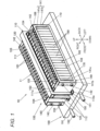
- FIG. 1 is a perspective outer view of an electricity storage module 10 according to a first embodiment of the present invention.
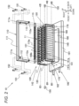
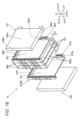
- FIG. 2 is an exploded perspective view illustrating a configuration of the electricity storage module 10.
- the electricity storage module 10 is composed of a cooling structure 190 and an electricity storage block 100.
- the electricity storage block 100 includes an element stacked body 11 in which a plurality of cell batteries 101 is stacked and arranged, an integration mechanism that integrates the element stacked body 11, and a duct unit 110 as a press device that presses the element stacked body 11 toward the cooling structure 190.
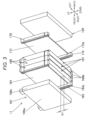
- FIG. 3 is an exploded perspective view illustrating a configuration of the element stacked body 11, showing part of the element stacked body 11.
- the element stacked body 11 includes the plurality of cell batteries 101 and a plurality of battery holders 160 and 170.
- Each of the cell batteries 101 is a flat rectangular parallelepiped and has a pair of wide side plates 109w.
- the plurality of cell batteries 101 constituting the element stacked body 11 is stacked and arranged such that the wide side plates 109w of the adjacent cell batteries 101 are opposed to each other.
- the adjacent cell batteries 101 are inversely oriented such that positive terminals 104 and negative terminals 105 provided on battery covers 108 are reversed in position.
- the positive terminals 104 and the negative terminals 105 of the adjacent cell batteries 101 are electrically connected together by a bus bar as a flat-plate metal conductive member. That is, the plurality of cell batteries 101 constituting the electricity storage block 100 according to this embodiment is electrically connected in series.
- the positive terminal 104 of the cell battery 101 arranged at the front end and the negative terminal 105 of the cell battery 101 arranged at the back end are electrically connected in series or in parallel by a conductive member to another electricity storage module or connected by a conductive member to a power-retrieval wire.
- FIG. 4 is a perspective view of the cell battery 101.
- the cell battery 101 includes a square battery container composed of a battery can 109 and the battery cover 108.
- the material for the battery can 109 and the battery cover 108 is aluminum or aluminum alloy, for example.
- the battery can 109 is a rectangular box having an opening 109a at one end.
- the battery cover 108 is a rectangular flat plate that is laser-welded to close the opening 109a of the battery can 109. That is, the battery cover 108 seals the battery can 109.
- the square battery container composed of the battery cover 108 and the battery can 109 is a hollow rectangular parallelepiped.
- the wide side plates 109w in a pair having the largest area surfaces (wide surface) out of the side surfaces constituting the battery container are opposed to each other
- narrow side plates 109n in a pair having the smallest area surfaces out of the side surfaces constituting the battery container are opposed to each other
- the battery cover 108 and a bottom plate 109b of the battery can 109 are opposed to each other.
- the battery cover 108 is provided with the positive terminal 104 and the negative terminal 105.
- the battery container stores a charging/discharging element (not illustrated) covered with an insulating case (not illustrated) .
- a positive electrode of the charging/discharging element not illustrated is connected to the positive terminal 104, and a negative electrode of the same is connected to the negative terminal 105. Accordingly, electric power is supplied to an external device via the positive terminal 104 and the negative terminal 105 or externally generated electric power is supplied to the charging/discharging element via the positive terminal 104 and the negative terminal 105 to charge the charging/discharging element.
- the battery cover 108 is provided with a liquid injection hole for injecting an electrolytic solution into the battery container.
- the liquid injection hole is sealed with a liquid injection stopper 108a after injection of the electrolytic solution.
- the electrolytic solution may be a non-aqueous electrolytic solution in which a lithium salt such as a hexafluoride lithium phosphate (LiPF6) is dissolved in a carbonate ester-based organic solvent such as an ethylene carbonate, for example.
- the battery cover 108 is provided with a gas exhaust valve 108b.
- the gas exhaust valve 108b is formed by partially thinning the battery cover 108 through press processing.
- the gas exhaust valve 108b is opened to eject the gas from the inside to reduce the pressure in the battery container.
- the plurality of cell batteries 101 is stacked and arranged in the front-back direction via the battery holders 160 and 170 to constitute the element stacked body 11.
- the material for the battery holders 160 and 170 is an insulating and heat-resistance resin, for example, an engineering plastic or rubber such as polybutylene terephthalate (PBT) or polycarbonate (PC).
- the battery holders 160 and 170 include intermediate holders 160 arranged between the adjacent cell batteries 101 and end holders 170 arranged between the cell battery 101 arranged at the front end and the end plate 120 and between the cell battery 101 arranged at the back end and the end plate 120.
- the material for the end plates 120 is a metal such as aluminum or aluminum alloy.
- the intervention of the intermediate holders 160 between the cell batteries 101 provides insulation between the adjacent cell batteries 101.
- the intervention of the end holders 170 between the end plates 120 and the cell batteries 101 provides insulation between the end plates 120 and the cell batteries 101.
- FIG. 5 is a perspective view of the intermediate holder 160.
- the intermediate holder 160 includes a wide surface abutment part 161 and a pair of connection parts 163 provided at the right and left ends of the wide surface abutment part 161.
- the wide surface abutment part 161 is a rectangular flat plate that is arranged between the adjacent cell batteries 101 as illustrated in FIG. 3 . As illustrated in FIGS. 3 and 5 , the front surface of the wide surface abutment part 161 is in abutment with the back-side wide side plate 109w of the cell battery 101 at the front side of the intermediate holder 160. The back surface of the wide surface abutment part 161 is in abutment with the front-side wide side plate 109w of the cell battery 101 at the back side of the intermediate holder 160.
- each of the connection parts 163 is an approximately rectangular parallelepiped with the longitudinal side along the up-down direction.
- the right-side connection part 163 has a fitting convex 163a extended in the up-down direction on the front surface and has a fitting concave 163b extended in the up-down direction on the back surface.
- the left-side connection part 163 has a fitting concave 163b extended in the up-down direction on the front surface and has a fitting convex 163a extended in the up-down direction on the back surface.
- the fitting convex 163a is fitted to the fitting concave 163b of the adjacent intermediate holder 160 or a fitting concave 173b of the adjacent end holder 170 described later.
- the fitting concave 163b is fitted to the fitting convex 163a of the adjacent intermediate holder 160 or a fitting convex 173a of the adjacent end holder 170 described later.
- the pair of connection parts 163 has inner surfaces 163s opposed to each other and divided into two in the front-back direction by the wide surface abutment part 161.
- the front-side inner surfaces 163s are in abutment with the narrow side plates 109n of the cell battery 101 at the front side of the intermediate holder 160.
- the back-side inner surfaces 163s are in abutment with the narrow side plates 109n of the cell battery 101 at the back side of the intermediate holder 160.
- convexes 167a protruding outward in the right-left direction.
- the convexes 167a are fitted to openings 143 of side frames 140 described later.
- the convexes 167a are positioned at the center in the up-down direction.
- abutment surface parts 167b Provided at the upper and lower sides of the convexes 167a are abutment surface parts 167b in abutment with side plates 141 of the side frames 140 described later.
- the wide surface abutment part 161 has a rectangular cutout 161c at the lower portion.
- the lower ends of the connection parts 163 protrude more downward than the wide surface abutment part 161.
- the lower end surfaces of the connection parts 163 are positioned more downward by a distance h1 than the lower end surface of the wide surface abutment part 161.
- the cell battery 101 is arranged such that the outer surface of the bottom plate 109b and the lower end surfaces of the connection parts 163 are flush with each other. That is, the outer surface of the bottom plate 109b of the cell battery 101 is positioned more downward by the distance h1 than the lower end surface of the wide surface abutment part 161.
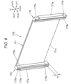
- FIG. 6 is a perspective view of the end holder 170.
- the end holder 170 includes a wide surface abutment part 171 and a pair of connection parts 173 provided at the right and left ends of the wide surface abutment part 171.
- the end holders 170 are arranged in the front-back direction as illustrated in FIG. 3 , that is, are arranged between the cell batteries 101 at both the ends of the element stacked body 11 in the direction of stacking and the end plates 120 described later.
- the end holder 170 positioned at the front end of the element stacked body 11 and the end holder 170 positioned at the back end of the element stacked body 11 are the same in shape. Accordingly, the end holder 170 positioned at the back end of the element stacked body 11 will be described later as a representative.
- FIG. 6 illustrates arrows that show the up-down, right-left, and front-back directions relative to the posture of the end holder 170 positioned at the back end of the element stacked body 11.
- the front surface of the wide surface abutment part 171 is in abutment with the back-side wide side plate 109w of the cell battery 101 at the front side of the end holder 170.
- the back surface of the wide surface abutment part 171 is in abutment with the end plate 120.
- connection parts 173 are approximately rectangular parallelepiped with the longitudinal side along the up-down direction.
- the right-side connection part 173 has a fitting convex 173a extended in the up-down direction on the front surface
- the left-side connection part 173 has a fitting concave 173b extended in the up-down direction on the front surface.
- the end holder 170 positioned at the front end of the element stacked body 11 is reversed 180 degrees with respect to the end holder 170 illustrated in FIG. 6 .
- the right-side connection part 173 has the fitting concave 173b extended in the up-down direction on the back surface
- the left-side connection part 173 has the fitting convex 173a extended in the up-down direction on the back surface.
- the fitting convexes 173a are fitted to the fitting concaves 163b of the adjacent intermediate holder 160.
- the fitting concaves 173b are fitted to the fitting convexes 163a of the adjacent intermediate holder 160.
- connection parts 173 protrudes forward from the wide surface abutment part 171.
- the pair of connection parts 173 has inner surfaces 173s opposed to each other in abutment with the narrow side plates 109n of the cell battery 101.
- convexes 177a Provided on the outer surfaces of the pair of connection parts 173 are convexes 177a protruding outward in the right-left direction.
- the convexes 177a are fitted to the openings 143 of the side frames 140 described later.
- the convexes 177a are positioned at the center in the up-down direction.
- Provided at the upper and lower sides of the convexes 177a have abutment surface parts 177b in abutment with the side plates 141 of the side frames 140 described later.
- the wide surface abutment part 171 has a rectangular cutout 171c at the lower portion.
- the lower ends of the connection parts 173 protrude more downward than the wide surface abutment part 171.
- the lower end surfaces of the connection parts 173 are positioned more downward by the distance h1 than the lower end surface of the wide surface abutment part 171.
- the cell battery 101 is arranged such that the outer surface of the bottom plate 109b and the lower end surfaces of the connection parts 173 are flush with each other. That is, the outer surface of the bottom plate 109b of the cell battery 101 is positioned more downward by the distance h1 than the lower end surface of the wide surface abutment part 171.
- the element stacked body 11 is held by an integration mechanism.
- the integration mechanism includes the pair of end plates 120 and the pair of side frames 140 to bind firmly the plurality of cell batteries 101 stacked and arranged via the battery holders 160 and 170.
- the end plates 120 are rectangular flat plates formed in almost the same size as the cell batteries 101.
- the pair of end plates 120 are arranged at the front and back sides of the element stacked body 11 to sandwich the element stacked body 11 in the front-back direction, that is, in the direction of stacking.
- each of the side frames 140 includes a side plate 141 as a rectangular flat plate with a rectangular opening 143 and bend parts 142 bending 90 degrees in the same direction at the front and back ends of the side plate 141.
- the side plate 141 includes a pair of side surface abutment parts 141a extended in parallel to each other between the front-side end plate 120 and the back-side end plate 120 and a pair of engagement parts 141b extended in parallel to each other between the upper and lower ends of the element stacked body 11, and have an approximately square-frame shape as seen from the right-left direction.
- Each of the side frames 140 is fabricated by cutting out a metal plate such as a stainless steel plate or steel plate in a predetermined width, punching the center of the plate, and folding and bending the ends of the plate.
- the convexes 167a of the intermediate holders 160 (see FIG. 5 ) and the convexes 177a of the end holders 170 (see FIG. 6 ) constitute rectangular parallelepiped-shaped convexes 168 as a whole.
- the openings 143 are adapted to the outer shape of the convexes 168.
- the side surface abutment parts 141a are in abutment with the abutment surface parts 167b of the intermediate holders 160 (see FIG. 5 ) and the abutment surface parts 177b of the end holders 170 (see FIG. 6 ).
- the upper and lower opening edges of the openings 143 engage with the upper and lower edges of the convexes 168, and the front and back opening edges of the openings 143 engage with the front and back edges of the convexes 177a of the end holders 170.
- the bend parts 142 While being in abutment with the end plates 120, the bend parts 142 are screwed into the end plates 120 by screws 150. When the bend parts 142 are screwed into the end plates 120, the battery holders 160 and 170 and the cell batteries 101 sandwiched between the pair of end plates 120 are held in the state of being compressed by a predetermined amount. In this manner, when the element stacked body 11 is firmly bound by the integration mechanism, the positions of the plurality of intermediate holders 160 and end holders 170 are regulated in the up-down, front-back, and right-left directions.
- the positions of the cell batteries 101 sandwiched between the battery holders 160 and 170 are regulated in the front-back direction, and the positions of the cell batteries 101 sandwiched between the pairs of connection parts 163 and 173 of the battery holders 160 and 170 are regulated in the right-left direction.
- the wide surface abutment parts 161 and 171 and the wide side plates 109w of the cell batteries 101 are in abutment with each other, and the inner surfaces 163s and 173s of the connection parts 163 and 173 and the narrow side plates 109n of the cell batteries 101 are in abutment with each other, whereby the positions of the cell batteries 101 are regulated in the up-down direction due to frictional force on the contact surfaces.
- the side frames 140 are fixed to the end plates 120 by use of the screws 150.
- the side frames 140 may be fixed to the end plates 120 by use of bolts or rivets or through swaging or welding.
- the cooling structure 190 has a rectangular parallelepiped-shaped heat transfer plate 191, a cooling pipe 192 arranged inside the heat transfer plate 191, and a thermally-conductive sheet 180 arranged on the heat transfer plate 191.
- the heat transfer plate 191 and the cooling pipe 192 are formed from highly thermal-conductive metal material such as aluminum or aluminum alloy.
- the cooling pipe 192 is a cylindrical pipe with a circular cross section that forms inside a refrigerant flow path through which a cooling heat medium such as an ethylene glycol solution (hereinafter, referred to as refrigerant) flows.
- refrigerant ethylene glycol solution
- the cooling pipe 192 is entirely U-shaped, has a folded part in the vicinity of the back end of the heat transfer plate 191 such that the refrigerant makes a U-turn, and has two straight pipe parts arranged along the front-back direction.
- a refrigerant inlet and a refrigerant outlet of the cooling pipe 192 are provided at the front end of the heat transfer plate 191.
- the refrigerant flowing through the cooling pipe 192 is supplied to the refrigerant inlet by a heat exchange system composed of a pump, a radiator, a cooling fan and the like.
- the refrigerant discharged from the refrigerant outlet is collected by the heat exchange system for cooling.
- the thermally-conductive sheet 180 is about 2 mm thick and has favorable thermal conductivity and electric insulation property.
- the thermally-conductive sheet 180 has preferably a thermal conductivity of about 1 to 5 W/m ⁇ K.
- the thermally-conductive sheet 180 is also of elasticity.
- a duct unit 110 is provided on the top of the element stacked body 11 to guide a gas discharged from the gas exhaust valves 108b of the plurality of cell batteries 101 to the outside of the vehicle.
- the duct unit 110 is formed from a metal plate such as a stainless steel plate or a steel plate.
- the duct unit 110 has a gas guide part 111 extended along the direction of stacking in the element stacked body 11, that is, along the front-back direction.
- the gas guide part 111 is a hollow rectangular pipe member that forms a gas flow path with a rectangular cross section from an upper plate, a lower plate, and a pair of side plates connecting the upper and lower plates.
- the gas guide part 111 has gas introduction openings formed in the lower plate at positions corresponding to the gas exhaust valves 108b of the cell batteries 101.
- a seal member 115 of an insulating resin is arranged at a part of connection between the gas exhaust valves 108b and the gas guide part 111.
- the seal member 115 extends in the front-back direction between the front-side end plate 120 and the back-side end plate 120.
- the seal member 115 has openings 115a at positions corresponding to the gas exhaust valves 108b of the cell batteries 101.
- the duct unit 110 has a pair of leg parts 112 extended downward from the front end of the gas guide part 111 and a pair of leg parts 112 extended downward from the back end of the gas guide part 111.
- Each of the leg parts 112 has a leg part attachment piece 112a to be screwed by a screw 151 into the heat transfer plate 191.
- the gas guide part 111 has guide part attachment pieces 111a to be screwed by screws 152 into the end plates 120 in the vicinities of the front and back ends of the gas guide part 111.
- Each of the cell batteries 101 is sandwiched between the wide surface abutment parts 161 and 171 of the battery holders 160 and 170, and sandwiched between the pair of connection parts 163 and 173 of the battery holders 160 and 170. Accordingly, frictional force acts on the contact surfaces of the wide surface abutment parts 161 and 171 and the wide side plates 109w of the cell battery 101 and the contact surfaces of the inner surfaces 163s and 173s of the connection parts 163 and 173 of the battery holders 160 and 170 and the narrow side plates 109n of the cell battery 101.
- the gas guide part 111 generates downward pressing force acting on battery covers 102 of the cell batteries 101 from the gas guide part 111 via the seal member 115.
- the duct unit 110 serves as a pressing device that presses the element stacked body 11 toward the thermally-conductive sheet 180 arranged on the heat transfer plate 191 (in other words, a pressing device that presses the heat transfer plate 191 toward the element stacked body 11).
- the duct unit 110 as a pressing device elastically deforms the thermally-conductive sheet 180 sandwiched between the element stacked body 11 and the heat transfer plate 191 such that the thermally-conductive sheet 180 is compressed by a predetermined amount, and holds the thermally-conductive sheet 180 in that state.
- the thermally-conductive sheet 180 can be closely attached to both the heat transfer surface of the element stacked body 11 and the heat transfer surface of the heat transfer plate 191, thereby resulting in efficient heat exchange.
- the element stacked body 11 and the heat transfer plate 191 in the electricity storage block 100 are thermally connected via the thermally-conductive sheet 180.
- thermally-conductive sheet 180 means that heat exchange between two objects is enabled by thermally-conductive solid materials such as a metal and a resin. Between the two thermally connected objects, heat flows from a higher-temperature object to a lower-temperature object until a thermal equilibrium is reached.
- the heat transfer plate 191 exchanges heat with the cell batteries 101 via the thermally-conductive sheet 180 to absorb the heat generated in the cell batteries 101, that is, cool down the cell batteries 101, thereby suppressing a temperature rise in the cell batteries 101.
- the heat transferred to the heat transfer plate 191 is then transferred to the refrigerant via the cooling pipe 192 and collected by the refrigerant into the heat exchange system.
- the duct unit 110 presses the element stacked body 11 against the thermally-conductive sheet 180 on the heat transfer plate 191
- compression reaction force acts on the duct unit 110 via the element stacked body 11 according to the amount of compression of the thermally-conductive sheet 180.
- the duct unit 110 is set in thickness, shape, dimensions, and material in order to ensure rigidity against the compression reaction force. By decreasing the reaction force acting on the duct unit 110, the weight of the duct unit 110 can be reduced.
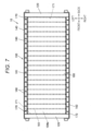
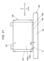
- FIG. 7 is a bottom view of the electricity storage block 100 and the thermally-conductive sheet 180. That is, FIG. 7 is a bottom view of the electricity storage module 10 without illustration of the heat transfer plate 191.
- the element stacked body 11 is pressed downward by the duct unit 110, and the thermally-conductive sheet 180 is sandwiched between the element stacked body 11 and the heat transfer plate 191 and compressed by a predetermined amount.
- the thermally-conductive sheet 180 is a rectangular sheet that has a front-back dimension almost the same as the front-back dimension of the element stacked body 11 and a right-left dimension slightly smaller than the right-left dimension of the element stacked body 11.
- the amount of compression of the thermally-conductive sheet 180 needs to be controlled without occurrence of permanent strain on the thermally-conductive sheet 180.
- the amount of compression of the thermally-conductive sheet 180 is set to about 0.2 to 0.4 mm taking into account variations in the dimensions of the cell batteries 101 pressed against the thermally-conductive sheet 180.
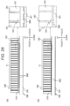
- FIG. 8 (a) is a diagram illustrating the state where the electricity storage block 100 and the cooling structure 190 are not yet thermally connected
- FIG. 8(b) is a diagram illustrating the state where the electricity storage block 100 and the cooling structure 190 are thermally connected
- FIGS. 8 (a) and 8 (b) illustrate schematically the cross section of the electricity storage module 10 from the left side, with partial enlarged views.
- the thermally-conductive sheet 180 When the element stacked body 11 is pressed against the thermally-conductive sheet 180, the thermally-conductive sheet 180 is compressed in the up-down direction (that is, the thickness direction), and is extended in the right-left and front-back directions. In addition, as illustrated in the partial enlargement view of FIG. 8(b) , a part of the thermally-conductive sheet 180 escapes and deforms in a gap between the adjacent cell batteries 101.
- the protrusion length h1 of the outer surfaces of the bottom plates 109b of the cell batteries 101 relative to the lower end surfaces of the wide surface abutment parts 161 can be set to be equal to or more than the thickness ts1 of the thermally-conductive sheet 180 (ts1 ⁇ h1), thereby to prevent contact between the wide surface abutment parts 161 and the thermally-conductive sheet 180.
- the thermally-conductive sheet 180 is compressed over the entire lower surface of the element stacked body 11. Accordingly, the lower end surfaces of the wide surface abutment parts 161 of the intermediate holders 160 are opposed to the thermally-conductive sheet 180. That is, as illustrated in the partial enlargement view of FIG. 8 (b) , the wide surface abutment parts 161 and the thermally-conductive sheet 180 are arranged on a predetermined virtual straight line VL extended in the up-down direction. Similarly, the lower end surfaces of the wide surface abutment parts 171 of the end holders 170 are opposed to the thermally-conductive sheet 180. That is, the wide surface abutment parts 171 and the thermally-conductive sheet 180 are arranged on a virtual straight line extended in the up-down direction.
- the wide surface abutment parts 161 and 171 are opposed to the thermally-conductive sheet 180.
- the wide surface abutment parts 161 and 171 have the cutouts 161c and 171c at the lower portions, and when the element stacked body 11 is pressed against the thermally-conductive sheet 180, the thermally-conductive sheet 180 and the lower end surfaces of the wide surface abutment parts 161 and 171 do not contact each other.
- the thermally-conductive sheet 180 and the lower end surfaces of the wide surface abutment parts 161 and 171 do not contact each other.
- only the bottom plates 109b of the battery cans 109 of the cell batteries 101 can be closely attached as a heat transfer surface to the thermally-conductive sheet 180.
- This embodiment was verified in the effect of reduction in compression reaction force with a comparative example in which the outer surfaces of the bottom plates 109b of the battery cans 109 and the lower end surfaces of the wide surface abutment parts 161 and 171 are flush with each other.
- the wide surface abutment parts 161 and 171 do not contact the thermally-conductive sheet 180, which reduces the contact area between the thermally-conductive sheet 180 and the element stacked body 11 as compared to the comparative example. That is, according to this embodiment, it is possible to increase the force per unit area applied to the bottom plates 109b of the cell batteries 101.
- the comparative example and this embodiment were compared in pressing force resulting from the compression of the thermally-conductive sheet 180 at the same compression rate (for example, 40%).
- this embodiment had pressing force (load) Fa necessary for the compression of the thermally-conductive sheet 180 at the compression rate of 40% and the comparative example had pressing force (load) Fb necessary for the compression of the thermally-conductive sheet 180 at the compression rate of 40%, Fa/Fb became about 0.8. That is, according to this embodiment, it is possible to reduce the compression reaction force resulting from the compressive deformation of the thermally-conductive sheet 180 by about 20 percent as compared to the case where the wide surface abutment parts 161 and 171 contact the thermally-conductive sheet 180.
- the cell batteries 101 constituting the element stacked body 11 closely to the thermally-conductive sheet 180, it is necessary to add pressing force taking into account variations in dimensions of the cell batteries 101.
- the compression reaction force can be reduced as described above. Accordingly, even when the cell batteries 101 are varied in dimensions, the cell batteries 101 can be thermally connected to the heat transfer plate 191 via the thermally-conductive sheet 180 in a stable manner.
- the element stacked body 11 includes the intermediate holders 160 that are arranged between the adjacent cell batteries 101 and are in abutment with the wide side plates 109w of the cell batteries 101 and the end holders 170 that are arranged between the cell batteries 101 and the end plates 120 and are in abutment with the wide side plates 109w of the cell batteries 101.
- the outer surfaces of the bottom plates 109b of the cell batteries 101, that is, the heat transfer surfaces of the cell batteries 101 protrude toward the heat transfer plate 191 more than the end surfaces of the wide surface abutment parts 161 and 171 at the heat transfer plate 191 side.
- single surfaces of the battery containers of the cell batteries 101 are attached closely to the thermally-conductive sheet 180 and the wide surface abutment parts 161 and 171 of the battery holders 160 and 170 are not in contact with the thermally-conductive sheet 180.
- the duct unit 110 and the integration mechanism can be simplified in structure to allow the electricity storage module 10 to be more lightweight and lower in costs.
- FIGS. 9 to 13 A second embodiment of the present invention will be described with reference to FIGS. 9 to 13 .
- the components identical or equivalent to those in the first embodiment are given the same reference signs as those in the first embodiment and descriptions thereof are omitted. The differences from the first embodiment will be described below in detail.
- FIG. 9 is similar to FIG. 3 , which is an exploded perspective view illustrating a configuration of an element stacked body 21 of an electricity storage module according to the second embodiment of the present invention.
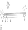
- FIG. 10 is a perspective view of an intermediate holder 260 constituting the element stacked body 21 illustrated in FIG. 9 .
- FIG. 10 illustrates the intermediate holder 260 positioned at the right end of the element stacked body 21 and a part of the cell battery 101 in abutment with the intermediate holder 260 by chain double-dashed lines.
- FIG. 11 is a perspective view of the end holder 170.
- each of the intermediate holders 160 is composed of the pair of connection parts 163 and the wide surface abutment part 161 provided between the pair of connection parts 163 (see FIG. 5 ) .
- each of the intermediate holders 260 is not provided with a wide surface abutment part in abutment with the wide side plate 109w of the cell battery 101 as illustrated in FIGS. 9 and 10 .
- an insulating film (not illustrated) with insulation property is firmly stuck to the outer surface of the battery container of the cell battery 101, and the adjacent cell batteries 101 are in contact with each other via the insulating film.
- the intermediate holders 260 are approximately rectangular parallelepiped with the longitudinal side along the up-down direction.
- the pair of intermediate holders 260 is arranged at the right and left of the cell battery 101 in abutment with the narrow side plates 109n of the cell battery 101.
- Each of the intermediate holders 260 is provided with a fitting convex 163a extended in the up-down direction along one side of the front-back direction and a fitting concave 163b extended in the up-down direction along the other side of the front-back direction.
- the right and left intermediate holders 260 in a pair are the same in shape.
- the right and left intermediate holders 260 in a pair are reversed 180 degrees.
- the right-side intermediate holder 260 has the fitting convex 163a at the front side and has the fitting concave 163b at the back side.
- the left-side intermediate holder 260 has the fitting concave 163b at the front side and has the fitting convex 163a at the back side.
- the fitting convex 163a is fitted to the fitting concave 163b of the adjacent intermediate holder 260 or a fitting concave 273b of the adjacent end holder 270.
- the fitting concave 163b is fitted to the fitting convex 163a of the adjacent intermediate holder 260 or a fitting convex 273a of the adjacent end holder 270.
- convexes 167a protruding outward in the right-left direction.
- the convexes 167a are fitted to the openings 143 of the side frames 140.
- the convexes 167a are positioned at the center in the up-down direction.
- abutment surface parts 167b Provided at the upper and lower sides of the convexes 167a are abutment surface parts 167b in abutment with side plates 141 of the side frames 140 described later.
- each of the end holders 270 includes a wide surface abutment part 271 and a pair of connection parts 273 provided at the right and left ends of the wide surface abutment part 271.
- the end holders 270 are almost rectangular flat plates and are arranged in the front-back direction as illustrated in FIG. 9 , that is, are arranged between the cell batteries 101 at both the ends of the element stacked body 21 in the direction of stacking and the end plates 120.
- the end holder 270 positioned at the front end of the element stacked body 21 and the end holder 270 positioned at the back end of the element stacked body 21 are the same in shape. Accordingly, the end holder 270 positioned at the back end of the element stacked body 21 will be described later as a representative.
- FIG. 11 illustrates arrows that show the up-down, right-left, and front-back directions relative to the posture of the end holder 270 positioned at the back end of the element stacked body 21.
- the front surface of the wide surface abutment part 271 is in abutment with the back-side wide side plate 109w of the cell battery 101 at the front side of the end holder 270.
- the back surface of the wide surface abutment part 271 is in abutment with the end plate 120 of the end holder 270.
- the right-side connection part 273 has the fitting convex 273a extended in the up-down direction on the front surface
- the left-side connection part 273 has the fitting concave 273b extended in the up-down direction on the front surface.
- the end holder 270 positioned at the front end of the element stacked body 21 is reversed 180 degrees with respect to the end holder 270 illustrated in FIG. 11 .
- the right-side connection part 273 has the fitting concave 273b extended in the up-down direction on the back surface
- the left-side connection part 273 has the fitting convex 273a extended in the up-down direction on the back surface.
- the fitting convexes 273a are fitted to the fitting concaves 163b of the adjacent intermediate holder 260.
- the fitting concaves 273b are fitted to the fitting convexes 163a of the adjacent intermediate holder 260.
- convexes 277a Provided on the right and left side surfaces of the pair of connection parts 273 are convexes 277a protruding outward in the right-left direction.
- the convexes 277a are fitted to the openings 143 of the side frames 140.
- the convexes 277a are positioned at the center in the up-down direction.
- Provided at the upper and lower sides of the convexes 277a have abutment surface parts 277b in abutment with the side plates 141 of the side frames 140.
- the wide surface abutment part 271 has a rectangular cutout 271c at the lower portion.
- the lower ends of the connection parts 273 protrude more downward than the wide surface abutment part 271.
- the lower end surfaces of the connection parts 273 are positioned more downward by the distance h1 than the lower end surface of the wide surface abutment part 271.
- the cell battery 101 is arranged such that the outer surface of the bottom plate 109b and the lower end surfaces of the connection parts 273 are flush with each other. That is, the outer surface of the bottom plate 109b of the cell battery 101 is positioned more downward by the distance h1 than the lower end surface of the wide surface abutment part 271.
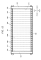
- FIG. 12 is similar to FIG. 7 , which is a bottom view of an electricity storage block 200 and the thermally-conductive sheet 180.
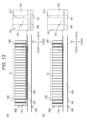
- FIGS. 13(a) and 13 (b) are similar to FIGS. 8 (a) and 8 (b) .
- FIG. 13 (a) is a diagram illustrating the state where the electricity storage block 200 and the cooling structure 190 are not yet thermally connected
- FIG. 13(b) is a diagram illustrating the state where the electricity storage block 200 and the cooling structure 190 are thermally connected.
- the lower end surfaces of the wide surface abutment parts 271 of the end holders 270 are opposed to the thermally-conductive sheet 180.
- the intermediate holders 160 have no wide surface abutment parts.
- the end holders 270 have cutouts 271c as in the first embodiment. This prevents the wide surface abutment parts 271 from contacting the thermally-conductive sheet 180 when the electricity storage block 200 and the cooling structure 190 are thermally connected.
- FIG. 14 is an exploded perspective view illustrating a configuration of an electricity storage module 30 according to the third embodiment of the present invention.
- FIG. 15 is a bottom view of an electricity storage block 300 and the thermally-conductive sheet 180.
- the outer surfaces of the bottom plates 109b of the cell batteries 101 serve as heat transfer surfaces attached closely to the thermally-conductive sheet 180, and the positive terminals 104 and the negative terminals 105 are provided on the cell covers 102 opposed to the bottom plates 109b (see FIG. 1 ).
- each of the cell batteries 101 has one of the narrow side plates 109n in a pair serving as a heat transfer surface attached closely to the thermally-conductive sheet 180 as illustrated in FIGS. 14 and 15 .
- the positive terminals 104 and the negative terminals 105 are arranged on a side surface of an element stacked body 31.
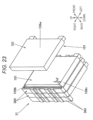
- FIG. 16 is similar to FIG. 3 , which is an exploded perspective view illustrating a configuration of the element stacked body 31.
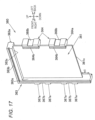
- FIG. 17 is a perspective view of an intermediate holder 360.
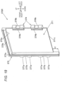
- FIGS. 18 and 19 are perspective views of a back-side end holder 370R and a front-side end holder 370F of the element stacked body 31.
- each of intermediate holders 360 has a wide surface abutment part 361, a first connection part 363 provided along the upper and right ends of the wide surface abutment part 361, and a pair of second connection parts 364 provided along the left end of the wide surface abutment part 361.
- the wide surface abutment part 361 is a rectangular flat plate that is arranged between the adjacent cell batteries 101 as illustrated in FIG. 16 . As illustrated in FIG. 17 , the front surface of the wide surface abutment part 361 is in abutment with the back-side wide side plate 109w of the cell battery 101 at the front side of the intermediate holder 360. The back surface of the wide surface abutment part 361 is in abutment with the front-side wide side plate 109w of the cell battery 101 at the back side of the intermediate holder 360.
- the wide surface abutment part 361 has a rectangular cutout 361c at the lower portion.
- the lower end of the first connection part 363 protrudes more downward than the wide surface abutment part 361.
- the lower end surface of the first connection part 363 is positioned more downward by the distance h1 than the lower end surface of the wide surface abutment part 361.
- the cell battery 101 is arranged such that the outer surface of the narrow side plate 109n arranged at the lower side and the lower end surface of the first connection part 363 are flush with each other. That is, the outer surface of the lower-side narrow side plate 109n of the cell battery 101 is positioned more downward by the distance h1 than the lower end surface of the wide surface abutment part 361.
- the first connection part 363 is approximately L-shaped as seen from the front-back direction.
- the first connection part 363 has a fitting concave 363b ranging from one to the other ends of the front surface, and has a fitting convex 363a ranging from one to the other ends of the back surface.
- the second connection parts 364 in a pair are the same in shape and are approximately rectangular parallelepipeds.
- Each of the second connection parts 364 has a fitting concave 364b extended in the up-down direction on the front surface, and a fitting convex 364a extended in the up-down direction on the back surface.
- the fitting convex 363a is fitted to the fitting concave 363b of the adjacent intermediate holder 360 or a fitting concave 373b of an adjacent end holder 370R described later.
- the fitting concave 363b is fitted to the fitting convex 363a of the adjacent intermediate holder 360 or a fitting convex 373a of the adjacent end holder 370F described later.
- the first connection part 363 has an inner surface 363s divided into two by the wide surface abutment part 361 in the front-back direction.
- the front-side inner surface 363s is in abutment with one of the narrow side plates 109n in a pair and the bottom plate 109b of the cell battery 101 at the front side of the intermediate holder 360.
- the back-side inner surface 363s is in abutment with one of the narrow side plates 109n in a pair and the bottom plate 109b of the cell battery 101 at the back side of the intermediate holder 360.
- each of the second connection parts 364 also has an inner surface 364s divided into two by the wide surface abutment part 361 in the front-back direction.
- the front-side inner surface 364s is in abutment with the battery cover 108 of the cell battery 101 at the front side of the intermediate holder 360.
- the back-side inner surface 364s is in abutment with the battery cover 108 of the cell battery 101 at the back side of the intermediate holder 360.
- the first connection part 363 has four convexes 367a protruding rightward on the outer surface.
- a fitting concave 367b is formed between the first and second convexes 367a from the top to fit with the side surface abutment part 141a of the side frame 140.
- a fitting concave 367b is formed between the third and fourth convexes 367a from the top to fit with the side surface abutment part 141a of the side frame 140.
- the second connection parts 364 in a pair are arranged at a predetermined space.
- the gas exhaust valve 108b of the battery cover 108 is arranged between the second connection parts 364 in a pair.
- Each of the second connection parts 364 has a fitting concave 368b to which the side surface abutment part 141a of the side frame 140 is fitted.
- the back-side end holder 370R arranged at the back end of the element stacked body 31 and the front-side end holder 370F arranged at the front end of the element stacked body 31 are approximately plane-symmetrical with respect to the plane orthogonal to the front-back direction. Accordingly, the back-side end holder 370R will be described as a representative with reference to FIGS. 16 and 18 . As for the front-side end holder 370F, only the parts different from the back-side end holder 370R will be described.
- the back-side end holder 370R has a wide surface abutment part 371, a first connection part 373 provided along the upper and right ends of the wide surface abutment part 371, and a pair of second connection parts 374 provided along the left end of the wide surface abutment part 371.
- the wide surface abutment part 371 is a rectangular flat plate that is arranged between the cell battery 101 and the end plate 120 as illustrated in FIG. 16 . As illustrated in FIGS. 16 and 18 , the front surface of the wide surface abutment part 371 is in abutment with the back-side wide side plate 109w of the cell battery 101 at the front side of the back-side end holder 370R. The back surface of the wide surface abutment part 371 is in abutment with the end plate 120.
- the wide surface abutment part 371 has a rectangular cutout 371c at the lower portion.
- the lower end of the first connection parts 373 protrudes more downward than the wide surface abutment part 371.
- the lower end surface of the first connection part 373 is positioned more downward by the distance h1 than the lower end surface of the wide surface abutment part 371.
- the cell battery 101 is arranged such that the outer surface of the narrow side plate 109n arranged at the lower side and the lower end surface of the first connection part 373 are flush with each other. That is, the outer surface of the lower-side narrow side plate 109n of the cell battery 101 is positioned more downward by the distance h1 than the lower end surface of the wide surface abutment part 371.
- the first connection part 373 is approximately L-shaped as seen from the front side.
- the first connection part 373 has a fitting concave 373b ranging from one to the other ends of the front surface.
- the fitting concave 373b is fitted in the convex 363a of the adjacent intermediate holder 360.
- the second connection parts 374 in a pair are the same in shape and are approximately rectangular parallelepipeds.
- Each of the second connection parts 374 has a fitting concave 374b extended in the up-down direction on the front surface.
- the fitting concave 374b is fitted to the fitting convex 364a of the adjacent intermediate holder 360.
- the first connection part 373 is provided to protrude forward from the wide surface abutment part 361.
- the inner surface 373s of the first connection part 373 is in abutment with one of the narrow side plates 109n in a pair and the bottom plate 109b of the cell battery 101 at the front side of the intermediate holder 360.
- the second connection parts 374 are also provided to protrude forward from the wide surface abutment part 371.
- the inner surfaces 364s of the second connection parts 374 are in abutment with the battery cover 108 of the cell battery 101 at the front side of the intermediate holder 360.
- the first connection part 373 has four convexes 377a protruding rightward on the outer surface.
- a fitting concave 377b is formed between the first and second convexes 377a from the top to fit with the side surface abutment part 141a of the side frame 140.
- a fitting concave 377b is formed between the third and fourth convexes 377a from the top to fit with the side surface abutment part 141a of the side frame 140.
- the second connection parts 364 in a pair are arranged at a predetermined space.
- the gas exhaust valve 108b of the battery cover 108 is arranged between the second connection parts 374 in a pair.
- Each of the second connection parts 374 has a fitting concave 378b to which the side surface abutment part 141a of the side frame 140 is fitted.
- the front-side end holder 370F and the back-side end holder 370R illustrated in FIG. 18 are approximately symmetric with respect to the plane orthogonal to the front-back direction. The two are different from each other in that, whereas the back-side end holder 370R has the fitting concaves 373b and 374b on the front surfaces of the first connection part 373 and the second connection parts 374, the front-side end holder 370F has the fitting convexes 373a and 374a on the back surfaces of the first connection part 373 and the second connection parts 374.
- the element stacked body 31 is integrated by connecting the first connection parts 363 and 373 and the second connection parts 364 and 374.
- the side surface abutment parts 141a of the left side frame 140 are fitted to the fitting concaves 368b and 378b of the element stacked body 31 (see FIG. 14 ).
- the side surface abutment parts 141a of the right side frame 140 are fitted to the fitting concaves 367b and 377b of the element stacked body 31 (see FIG. 14 ).
- the second connection parts 374 of the front-side end holder 370F are fitted to the front-side engagement part 141b of the left side frame 140
- the second connection parts 374 of the back-side end holder 370R are fitted to the back-side engagement part 141b of the left side frame 140.
- the convexes 377a of the first connection part 373 of the front-side end holder 370F engage with the front-side engagement part 141b of the right side frame 140
- the convexes 377a of the first connection part 373 of the back-side end holder 370R engage with the back-side engagement part 141b of the left side frame 140.
- the bend parts 142 of the side frames 140 are screwed into the end plates 120 by the screws 150.
- the element stacked body 31 is sandwiched and compressed by a predetermined amount between the pair of end plates 120 in the direction of stacking.
- the duct unit 110 has the guide part attachment pieces 111a screwed by the screws 152 into the end plates 120 and the leg part attachment pieces 112a screwed by the screws 151 into the heat transfer plate 191.
- the element stacked body 31 is pressed downward and the narrow side plates 109n of the cell battery 101 constituting the lower surface of the element stacked body 31 are closely attached to the thermally-conductive sheet 180.
- the wide surface abutment parts 361 and 371 of the battery holders 360, 370F, and 370R are provided with the cutouts 361c and 371c. This prevents the wide surface abutment parts 361 and 371 from contacting the thermally-conductive sheet 180 when the electricity storage block 300 and the cooling structure 190 are thermally connected.
- FIG. 21 is a bottom view of the intermediate holder 160 and the cell battery 101 illustrated in FIG. 20 .
- the lower end surfaces of the connection parts 163 are positioned more downward than the outer surface of the bottom plate 109b.
- the lower ends of the connection parts 163 are set as plate abutment parts protruding toward the heat transfer plate 191 more than the heat transfer surface of the cell battery 101.
- the lower end surfaces of the connection parts 163 abut directly with the surface of the heat transfer plate 191 when the electricity storage block 100 is thermally connected to the cooling structure 190 and the thermally-conductive sheet 180 is compressed by a predetermined amount.
- connection parts 163 When the lower end surfaces of the connection parts 163 abut with the heat transfer plate 191, a space A is formed and surrounded by the inner surfaces 163s of the connection parts 163 and the inner surfaces 173s of the connection parts 173, the outer surface of the bottom plate 109b of the cell battery 101, the heat transfer plate 191, and the pair of end plates 120.
- the thermally-conductive sheet 180 is arranged in the space A.
- the distance h2 between the lower end surfaces of the connection parts 163 and the outer surface of the bottom plate 109b of the cell battery 101 is set taking into account the compression ratio of the thermally-conductive sheet 180.
- the thickness of the thermally-conductive sheet 180 before the compression is designated as ts1
- the relationship 0 ⁇ h2 ⁇ ts1 needs to be satisfied to compress the thermally-conductive sheet 180.
- the thermally-conductive sheet 180 is compressed until the lower end surfaces of the connection parts 163 abut with the heat transfer plate 191. Accordingly, a thickness ts2 of the thermally-conductive sheet 180 after the compression becomes equal to h2.
- the thermally-conductive sheet 180 is compressed at a compression ratio of (ts1 - ts2) ⁇ 100/ts1 (%).
- the thermally-conductive sheet 180 When being compressed in the up-down direction (thickness direction), the thermally-conductive sheet 180 is deformed and extended in the front-back and right-left directions. Accordingly, the thermally-conductive sheet 180 is made slightly smaller in dimensions than the dimensions of the space A in the front-back and right-left directions, so that the dimensions of the thermally-conductive sheet 180 after the compression in the front-back and right-left directions fall within the space A.
- the thickness ts2 of the thermally-conductive sheet 180 after the compression can be equal to the distance h2. It is necessary to control the compression ratio such that the thermally-conductive sheet 180 causes no permanent strain. According to this modification example, however, the thickness ts2 of the thermally-conductive sheet 180 after the compression is determined by the protrusion length h2 of the connection parts 163 and 173 and the end plates 120, which facilitates the control of the compression ratio. Further, since the battery holders 160 and 170 and the end plates 120 are in abutment with the heat transfer plate 191, vibration and impact acting on the electricity storage module 10 are more stable than those in the first embodiment.
- the lower end surfaces of the intermediate holders 260 may be positioned more downward than the outer surfaces of the bottom plates 109b of the cell batteries 101 in order to allow the lower end surfaces of the intermediate holders 260 to abut with the heat transfer plate 191 (not according to the invention).
- the lower end surfaces of the connection parts 273 of the end holders 270 may be positioned more downward than the outer surfaces of the bottom plates 109b of the cell batteries 101 in order to allow the lower end surfaces of the connection parts 273 of the end holders 270 abut with the heat transfer plate 191.
- the lower end surfaces of the first connection parts 363 of the intermediate holders 360 may be positioned more downward than the outer surfaces of the narrow side plates 109n of the cell batteries 101.
- the lower surfaces of the first connection parts 373 of the end holders 370F and 370R may be positioned more downward than the outer surfaces of the narrow side plates 109n of the cell batteries 101 in order to allow the lower end surfaces of the first connection parts 373 of the end holders 370F and 370R to abut with the heat transfer plate 191.
- the method for connecting the duct unit 110 and the heat transfer plate 191 is not limited to the foregoing one.
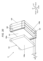
- the end plates 120 may be fixed to the heat transfer plate 191 by use of L-shaped brackets 499 and screws 498.
- the two each L-shaped brackets 499 are attached to the pair of end plates 120.
- one thermally-conductive sheet 180 is arranged on the heat transfer plate 191.
- the present invention is not limited to this configuration.
- a strip-like thermally-conductive sheet 580 may be arranged in correspondence with the bottom plate 109b of each cell battery 101, as illustrated in FIG. 25 .
- the wide surface abutment parts 161 of the intermediate holders 160 and the wide surface abutment parts 171 of the end holders 170 do not contact the thermally-conductive sheets 580, and only the bottom plates 109b of the cell batteries 101 are closely attached to the thermally-conductive sheets 580, thereby reducing the compression reaction force.
- the thermally-conductive sheet 180 has favorable heat conductivity and favorable electric insulating properties.
- the present invention is not limited to this configuration. A thermally-conductive sheet with favorable heat conductivity and an insulating sheet with favorable electric insulating properties may be stacked.
- the element stacked bodies 11, 21, and 31 are composed of a plurality of cell batteries 101 and battery holders 160, 170, 260, 270, 360, 370F, and 370R.
- the present invention is not limited to this configuration.
- spacers may be arranged between the end holders 170 and the cell batteries 101 or between the end holders 170 and the end plates 120 in order to adjust the dimensions of the element stacked body 11 in the longitudinal direction (direction of stacking).
- such spacers may be arranged.
- the end plates 120 or the battery containers of the cell batteries 101 may be provided with insulating properties to eliminate the end holders 170, 270, 370F, and 370R.
- only single side surfaces of the cell batteries 101 are the heat transfer surfaces of the cell batteries 101 to be closely attached to the thermally-conductive sheet 180 of the element stacked bodies 11, 21, and 31.
- the heat transfer surfaces of the cell batteries 101 may protrude more downward than the lower end surfaces of the wide surface abutment parts 161, 171, 271, 361, and 371.
- the lower end surfaces of the wide surface abutment parts 161 may contact a part of the thermally-conductive sheet 180 elastically deformed and escaped between the cell batteries 101. This reduces the compression reaction force as compared to the case where the lower end surfaces of the wide surface abutment parts 161 and 171 and the outer surface of the bottom plates 109b of the cell batteries 101 are flush with each other.
- the thermally-conductive sheet 180 may be used in combination with an insulating thermally-conductive gel such as silicon oil.
- the use of the thermally-conductive gel allows the heat transfer surfaces of the element stacked bodies 11, 21, and 31 and the surface of the heat transfer plate 191 to be closely attached to the thermally-conductive sheet 180. Further, in the case of using the thermally-conductive sheet 180 and the thermally-conductive gel in combination, the thermally-conductive gel plays the role of absorbing variations in the dimensions of the battery containers of the cell batteries 101. This reduces the amount of compression of the thermally-conductive sheet 180 as compared to the case of using the thermally-conductive sheet 180 alone.
- the cooling pipe 192 is arranged on the heat transfer plate 191.
- the present invention is not limited to this configuration.
- a heating pipe may be arranged on the heat transfer plate 191 to circulate a heating medium for heating the heat transfer plate 191.
- Providing the heating pipe could heat in advance the electricity storage module for use in cold climate regions or in winter season to temperatures at which the electricity storage module can offer sufficient performance.
- including the heating pipe and the cooling pipe 192 would allow temperature adjustment within the temperature range suited to the cell batteries 101.
- the electricity storage module 10 is incorporated into an electricity storage device installed in a hybrid electric automobile or a purely electric automobile.
- the present invention is not limited to this configuration.
- the present invention may also be applied to electricity storage modules usable for electricity storage devices in other electric vehicles (moving vehicles), for example, railway vehicles such as hybrid trains, shared vehicles such as buses, cargo vehicles such as motor trucks, industrial vehicles such as turret vehicles and battery-powered forklift trucks, construction machines such as cranes and loading shovels, driverless moving vehicles, and golf carts.
- the present invention may also be applied to electricity storage modules incorporated into stationary electricity storage devices.
- the present invention may also be applied as a power source for medical instruments, power storage systems, and elevators.
- the present invention can be used as an electricity storage system that charges electricity storage elements by solar power or wind power for electricity storage.
- the present invention can also be used as an electricity storage system that charges electricity storage elements by night-time power.
- the present invention can also be used as an electricity storage system usable at places beyond the earth such as space stations, space ships, or space ports.
- the lithium-ion secondary batteries are taken as an example of electricity storage elements.
- the present invention is also applicable to other secondary batteries such as nickel-hydrogen batteries.
- the present invention can also be applied to electricity storage modules having electric double-layer capacitors and lithium-ion capacitors as electricity storage elements.
Claims (4)
- Elektrizitätsspeichermodul, das umfasst:ein quadratisches Elektrizitätsspeicherelement (101) mit einem Paar breiter Flächen und einem Paar schmaler Flächen;ein Halterelement (160, 170), das so angeordnet ist, dass es einer breiten Fläche des quadratischen Elektrizitätsspeicherelements (101) gegenüberliegt;eine thermisch leitende Folie (180), die eine schmale Fläche des quadratischen Elektrizitätsspeicherelements (101) berührt;eine Wärmeübertragungsplatte (191), die die thermisch leitende Folie (180) berührt, wobeidie schmale Fläche des quadratischen Elektrizitätsspeicherelements (101) so angeordnet ist, dass sie um eine Vorsprungslänge (h1) mehr in Richtung der thermisch leitenden Folie (180) als eine Fläche des Halterelements gegenüber der breiten Fläche des quadratischen Elektrizitätsspeicherelements (101) vorsteht;dadurch gekennzeichnet, dasseine Dicke (ts) der thermisch leitenden Folie (180), bevor das quadratische Elektrizitätsspeicherelement (101) auf der thermische leitenden Folie (180) befestigt wird, gleich der Vorsprungslänge (h1) oder kleiner als diese ist.
- Elektrizitätsspeichermodul nach Anspruch 1, das ferner umfasst:
ein Druckelement, das das quadratische Elektrizitätsspeicherelement in Richtung der Wärmeübertragungsplatte (191) drückt. - Elektrizitätsspeichermodul nach Anspruch 2, wobei:
das Druckelement ein Leitungselement ist, durch das ein Gas, das von dem quadratischen Elektrizitätsspeicherelement erzeugt wird, fließt. - Elektrizitätsspeichermodul nach Anspruch 1, wobei:
das Halterelement an einem Ende einer Elektrizitätsspeichergruppe angeordnet ist, wo mehrere quadratische Elektrizitätsspeicherelemente (101), die jeweils dem quadratischen Elektrizitätsspeicherelement (101) entsprechen, gestapelt sind.
Applications Claiming Priority (4)
| Application Number | Priority Date | Filing Date | Title |
|---|---|---|---|
| JP2013119729A JP6174381B2 (ja) | 2013-06-06 | 2013-06-06 | 蓄電ブロックおよび蓄電モジュール |
| PCT/JP2014/064048 WO2014196422A1 (ja) | 2013-06-06 | 2014-05-28 | 蓄電ブロックおよび蓄電モジュール |
| EP14807786.0A EP3007249B1 (de) | 2013-06-06 | 2014-05-28 | Elektrizitätsspeicherblock und elektrizitätsspeichermodul |
| JP2017132714A JP6348641B2 (ja) | 2013-06-06 | 2017-07-06 | 蓄電モジュール、電池モジュールの製造方法 |
Related Parent Applications (2)
| Application Number | Title | Priority Date | Filing Date |
|---|---|---|---|
| EP14807786.0A Division-Into EP3007249B1 (de) | 2013-06-06 | 2014-05-28 | Elektrizitätsspeicherblock und elektrizitätsspeichermodul |
| EP14807786.0A Division EP3007249B1 (de) | 2013-06-06 | 2014-05-28 | Elektrizitätsspeicherblock und elektrizitätsspeichermodul |
Publications (2)
| Publication Number | Publication Date |
|---|---|
| EP3407403A1 EP3407403A1 (de) | 2018-11-28 |
| EP3407403B1 true EP3407403B1 (de) | 2024-03-20 |
Family
ID=61661276
Family Applications (2)
| Application Number | Title | Priority Date | Filing Date |
|---|---|---|---|
| EP18171859.4A Active EP3407403B1 (de) | 2013-06-06 | 2014-05-28 | Elektrizitätsspeicherblock und elektrizitätsspeichermodul |
| EP14807786.0A Active EP3007249B1 (de) | 2013-06-06 | 2014-05-28 | Elektrizitätsspeicherblock und elektrizitätsspeichermodul |
Family Applications After (1)
| Application Number | Title | Priority Date | Filing Date |
|---|---|---|---|
| EP14807786.0A Active EP3007249B1 (de) | 2013-06-06 | 2014-05-28 | Elektrizitätsspeicherblock und elektrizitätsspeichermodul |
Country Status (5)
| Country | Link |
|---|---|
| US (2) | US9887440B2 (de) |
| EP (2) | EP3407403B1 (de) |
| JP (2) | JP6174381B2 (de) |
| CN (2) | CN105264688B (de) |
| WO (1) | WO2014196422A1 (de) |
Families Citing this family (39)
| Publication number | Priority date | Publication date | Assignee | Title |
|---|---|---|---|---|
| JP5835315B2 (ja) * | 2013-12-26 | 2015-12-24 | 株式会社豊田自動織機 | 蓄電モジュールユニット及び蓄電モジュールユニットの製造方法 |
| WO2016076056A1 (ja) * | 2014-11-10 | 2016-05-19 | 株式会社豊田自動織機 | 電池モジュール |
| KR101806415B1 (ko) * | 2014-12-19 | 2017-12-07 | 주식회사 엘지화학 | 냉각효율이 향상된 이차전지 셀 및 이를 포함하는 모듈형 전지 |
| JP6609989B2 (ja) * | 2015-05-20 | 2019-11-27 | 株式会社豊田自動織機 | 電池モジュール |
| US10199621B2 (en) * | 2015-06-11 | 2019-02-05 | Ford Global Technologies, Llc | Battery cell spacer for establishing dielectric barriers within a battery assembly |
| US10658716B2 (en) | 2015-09-24 | 2020-05-19 | Lg Chem, Ltd. | Battery module |
| US10084217B2 (en) * | 2016-02-16 | 2018-09-25 | Lg Chem, Ltd. | Battery system |
| KR102072764B1 (ko) * | 2016-03-03 | 2020-02-03 | 주식회사 엘지화학 | 배터리 모듈 및 이를 포함하는 배터리 팩, 자동차 |
| JP6615714B2 (ja) * | 2016-07-29 | 2019-12-04 | 本田技研工業株式会社 | 電気自動車用のバッテリパック |
| DE102016009212A1 (de) * | 2016-08-01 | 2018-02-01 | Audi Ag | Batteriemodul und Batterie |
| WO2018042763A1 (ja) * | 2016-08-29 | 2018-03-08 | 三洋電機株式会社 | 電源装置 |
| WO2018163816A1 (ja) * | 2017-03-07 | 2018-09-13 | パナソニックIpマネジメント株式会社 | セパレータ、電池モジュール及び電池モジュールの製造方法 |
| JP6928826B2 (ja) * | 2017-04-12 | 2021-09-01 | パナソニックIpマネジメント株式会社 | 電池モジュールおよび蓄電ユニット |
| WO2019039116A1 (ja) * | 2017-08-22 | 2019-02-28 | 日立オートモティブシステムズ株式会社 | 電池パック |
| CN109599632B (zh) * | 2017-09-30 | 2020-11-20 | 比亚迪股份有限公司 | 车载电池的温度调节方法和温度调节系统 |
| JP6965717B2 (ja) * | 2017-12-13 | 2021-11-10 | トヨタ自動車株式会社 | 電池パックの製造方法 |
| JP6923007B2 (ja) * | 2018-01-31 | 2021-08-18 | 株式会社豊田自動織機 | 蓄電装置 |
| US11791516B2 (en) | 2018-03-23 | 2023-10-17 | Gs Yuasa International Ltd. | Energy storage apparatus |
| CN110323371B (zh) * | 2018-03-29 | 2021-02-12 | 宁德时代新能源科技股份有限公司 | 电池模组 |
| JP7310095B2 (ja) * | 2018-03-30 | 2023-07-19 | トヨタ自動車株式会社 | 電池温度調節装置 |
| FR3062521B1 (fr) * | 2018-04-10 | 2023-09-08 | Sogefi Air & Cooling | Unite de batterie avec des moyens de regulation de la temperature integres au boitier |
| JP2020030970A (ja) * | 2018-08-22 | 2020-02-27 | 株式会社デンソー | 電池モジュール |
| EP3859816A4 (de) * | 2018-09-26 | 2022-07-13 | Vehicle Energy Japan Inc. | Batteriesatz |
| DE112019006321T5 (de) * | 2018-12-20 | 2021-10-07 | Kabushiki Kaisha Toyota Jidoshokki | Stromspeichervorrichtung |
| CN209401679U (zh) * | 2018-12-29 | 2019-09-17 | 宁德时代新能源科技股份有限公司 | 电池箱 |
| JP7319376B2 (ja) | 2019-01-09 | 2023-08-01 | ビーワイディー カンパニー リミテッド | 電池パック及び電気自動車 |
| JP7151493B2 (ja) * | 2019-01-15 | 2022-10-12 | トヨタ自動車株式会社 | 電池装置 |
| KR102640879B1 (ko) * | 2019-02-08 | 2024-02-23 | 에스케이온 주식회사 | 배터리 모듈 및 이의 제조방법 |
| US11505143B2 (en) * | 2019-02-27 | 2022-11-22 | Ford Global Technologies, Llc | Supercapacitor mounting assemblies and vehicle mounting locations |
| DE102019207357A1 (de) * | 2019-05-20 | 2020-11-26 | Audi Ag | Verfahren zum Einbringen eines Wärmeleitmittels zwischen ein Batteriemodul und einen Kühlboden, Injektionssystem und Batteriemodul |
| JP7267129B2 (ja) * | 2019-07-10 | 2023-05-01 | 本田技研工業株式会社 | 蓄電モジュール |
| CN114207912A (zh) * | 2019-08-07 | 2022-03-18 | 三洋电机株式会社 | 电源装置和使用该电源装置的电动车辆以及蓄电装置 |
| CN110994044B (zh) * | 2019-11-11 | 2022-06-24 | 安徽理士电源技术有限公司 | 带有保护结构的铅酸蓄电池 |
| JP7259721B2 (ja) * | 2019-12-02 | 2023-04-18 | トヨタ自動車株式会社 | 電池モジュール |
| JP7333001B2 (ja) * | 2019-12-26 | 2023-08-24 | トヨタ自動車株式会社 | 組電池および電池ホルダー |
| JPWO2021187114A1 (de) * | 2020-03-18 | 2021-09-23 | ||
| US20230246274A1 (en) * | 2020-03-31 | 2023-08-03 | Sanyo Electric Co., Ltd. | Power source device, and vehicle and power storage device each equipped with same |
| KR20210122593A (ko) * | 2020-04-01 | 2021-10-12 | 삼성에스디아이 주식회사 | 배터리 팩 |
| US11877423B2 (en) * | 2020-10-08 | 2024-01-16 | Toyota Motor Engineering And Manufacturing North America, Inc. | Battery thermal management with large area planar heat pipes |
Family Cites Families (17)
| Publication number | Priority date | Publication date | Assignee | Title |
|---|---|---|---|---|
| JP2002216731A (ja) * | 2001-01-23 | 2002-08-02 | Toyota Motor Corp | バッテリのガス排出構造 |
| JP5181327B2 (ja) * | 2007-10-25 | 2013-04-10 | 本田技研工業株式会社 | 蓄電装置 |
| JP2009135088A (ja) * | 2007-10-29 | 2009-06-18 | Panasonic Corp | 電池パックおよび電池搭載機器 |
| JP5334420B2 (ja) | 2008-01-16 | 2013-11-06 | 三洋電機株式会社 | バッテリシステム |
| JP2009301877A (ja) * | 2008-06-13 | 2009-12-24 | Toyoda Gosei Co Ltd | 組電池装置 |
| JP2010192207A (ja) * | 2009-02-17 | 2010-09-02 | Mitsubishi Heavy Ind Ltd | 電池用冷却装置及び組電池 |
| JP2010251019A (ja) * | 2009-04-13 | 2010-11-04 | Sanyo Electric Co Ltd | バッテリシステム |
| JP2011034775A (ja) | 2009-07-31 | 2011-02-17 | Sanyo Electric Co Ltd | 組電池の冷却構造、及び、バッテリーシステム |
| KR101084933B1 (ko) * | 2009-12-04 | 2011-11-17 | 삼성에스디아이 주식회사 | 이차 전지 모듈 및 이차 전지 모듈의 전지 스페이서 |
| JP2011171029A (ja) * | 2010-02-17 | 2011-09-01 | Sanyo Electric Co Ltd | 電池モジュール |
| EP2599154B1 (de) * | 2010-07-29 | 2016-11-30 | E4V | System zur kühlung einer elektrischen batterie und batterie mit einem derartigen system |
| JP5804323B2 (ja) * | 2011-01-07 | 2015-11-04 | 株式会社Gsユアサ | 蓄電素子及び蓄電装置 |
| WO2012117681A1 (ja) * | 2011-02-28 | 2012-09-07 | 三洋電機株式会社 | 電池モジュールおよび電池モジュールの製造方法 |
| US9859532B2 (en) * | 2011-03-31 | 2018-01-02 | Johnson Controls Technology Llc | Battery module and method incorporating exterior casing and liner |
| KR101199148B1 (ko) * | 2011-04-21 | 2012-11-09 | 에스비리모티브 주식회사 | 배터리 모듈 |
| JP2012248339A (ja) * | 2011-05-25 | 2012-12-13 | Sanyo Electric Co Ltd | 電力用の電源装置及び電源装置を備える車両 |
| JPWO2017169729A1 (ja) * | 2016-03-30 | 2019-02-14 | 三洋電機株式会社 | バッテリパック |
-
2013
- 2013-06-06 JP JP2013119729A patent/JP6174381B2/ja active Active
-
2014
- 2014-05-28 EP EP18171859.4A patent/EP3407403B1/de active Active
- 2014-05-28 CN CN201480032080.7A patent/CN105264688B/zh active Active
- 2014-05-28 EP EP14807786.0A patent/EP3007249B1/de active Active
- 2014-05-28 US US14/895,665 patent/US9887440B2/en active Active
- 2014-05-28 WO PCT/JP2014/064048 patent/WO2014196422A1/ja active Application Filing
- 2014-05-28 CN CN201710784618.5A patent/CN107681076B/zh active Active
-
2017
- 2017-07-06 JP JP2017132714A patent/JP6348641B2/ja active Active
- 2017-12-26 US US15/854,297 patent/US11670814B2/en active Active
Also Published As
| Publication number | Publication date |
|---|---|
| EP3007249A1 (de) | 2016-04-13 |
| EP3007249B1 (de) | 2018-07-11 |
| CN107681076B (zh) | 2020-12-08 |
| CN105264688B (zh) | 2017-10-03 |
| EP3007249A4 (de) | 2017-02-01 |
| JP2014238928A (ja) | 2014-12-18 |
| JP6174381B2 (ja) | 2017-08-02 |
| CN107681076A (zh) | 2018-02-09 |
| EP3407403A1 (de) | 2018-11-28 |
| US11670814B2 (en) | 2023-06-06 |
| US20180123199A1 (en) | 2018-05-03 |
| JP2017212214A (ja) | 2017-11-30 |
| US20160141737A1 (en) | 2016-05-19 |
| JP6348641B2 (ja) | 2018-06-27 |
| WO2014196422A1 (ja) | 2014-12-11 |
| US9887440B2 (en) | 2018-02-06 |
| CN105264688A (zh) | 2016-01-20 |
Similar Documents
| Publication | Publication Date | Title |
|---|---|---|
| EP3407403B1 (de) | Elektrizitätsspeicherblock und elektrizitätsspeichermodul | |
| EP2538466B1 (de) | Batteriemodul mit erfassungselementen mit einer neuen struktur | |
| JP5883944B2 (ja) | 安全性の向上した電池モジュール及びこれを含む電池パック | |
| KR101601568B1 (ko) | 전기자동차의 전원 공급 유닛 | |
| JP5743356B2 (ja) | バッテリー・モジュールとこれを含むバッテリーパック | |
| US10586952B2 (en) | Battery module comprising cartridge having gripping part | |
| JP5527172B2 (ja) | 蓄電装置 | |
| EP2691999B1 (de) | Batteriemodul mit umgehäuse und auskleidung | |
| US8551632B2 (en) | Battery cooling system | |
| CN103069284B (zh) | 电压感测组件和采用电压感测组件的电池模块 | |
| KR101431717B1 (ko) | 신규한 구조의 버스 바 | |
| US8778528B2 (en) | Electricity storage device | |
| US20130045403A1 (en) | Battery module having novel structure | |
| JP5472059B2 (ja) | 蓄電装置 | |
| KR20150140120A (ko) | 배터리 팩 | |
| JP6149670B2 (ja) | 電池モジュール | |
| JP2014513380A (ja) | エネルギー貯蔵装置 | |
| CN104412439A (zh) | 具有间接空气冷却结构的电池模块 | |
| JP6506307B2 (ja) | スペーサーを含む電池パック | |
| JP2013222554A (ja) | 蓄電装置 | |
| EP4350726A1 (de) | Energiespeichervorrichtung |
Legal Events
| Date | Code | Title | Description |
|---|---|---|---|
| PUAI | Public reference made under article 153(3) epc to a published international application that has entered the european phase |
Free format text: ORIGINAL CODE: 0009012 |
|
| STAA | Information on the status of an ep patent application or granted ep patent |
Free format text: STATUS: REQUEST FOR EXAMINATION WAS MADE |
|
| 17P | Request for examination filed |
Effective date: 20180620 |
|
| AC | Divisional application: reference to earlier application |
Ref document number: 3007249 Country of ref document: EP Kind code of ref document: P |
|
| AK | Designated contracting states |
Kind code of ref document: A1 Designated state(s): AL AT BE BG CH CY CZ DE DK EE ES FI FR GB GR HR HU IE IS IT LI LT LU LV MC MK MT NL NO PL PT RO RS SE SI SK SM TR |
|
| STAA | Information on the status of an ep patent application or granted ep patent |
Free format text: STATUS: REQUEST FOR EXAMINATION WAS MADE |
|
| RAP1 | Party data changed (applicant data changed or rights of an application transferred) |
Owner name: VEHICLE ENERGY JAPAN INC. |
|
| STAA | Information on the status of an ep patent application or granted ep patent |
Free format text: STATUS: EXAMINATION IS IN PROGRESS |
|
| 17Q | First examination report despatched |
Effective date: 20210927 |
|
| STAA | Information on the status of an ep patent application or granted ep patent |
Free format text: STATUS: EXAMINATION IS IN PROGRESS |
|
| REG | Reference to a national code |
Ref document number: 602014089757 Country of ref document: DE Ref country code: DE Ref legal event code: R079 Free format text: PREVIOUS MAIN CLASS: H01M0002100000 Ipc: H01M0010613000 |
|
| RIC1 | Information provided on ipc code assigned before grant |
Ipc: H01M 50/209 20210101ALN20230712BHEP Ipc: H01M 10/627 20140101ALN20230712BHEP Ipc: H01M 10/625 20140101ALN20230712BHEP Ipc: H01M 50/249 20210101ALN20230712BHEP Ipc: H01M 50/251 20210101ALN20230712BHEP Ipc: H01M 10/647 20140101ALI20230712BHEP Ipc: H01M 10/6556 20140101ALI20230712BHEP Ipc: H01M 10/6555 20140101ALI20230712BHEP Ipc: H01M 10/04 20060101ALI20230712BHEP Ipc: H01M 10/613 20140101AFI20230712BHEP |
|
| RIC1 | Information provided on ipc code assigned before grant |
Ipc: H01M 50/209 20210101ALN20230714BHEP Ipc: H01M 10/627 20140101ALN20230714BHEP Ipc: H01M 10/625 20140101ALN20230714BHEP Ipc: H01M 50/249 20210101ALN20230714BHEP Ipc: H01M 50/251 20210101ALN20230714BHEP Ipc: H01M 10/647 20140101ALI20230714BHEP Ipc: H01M 10/6556 20140101ALI20230714BHEP Ipc: H01M 10/6555 20140101ALI20230714BHEP Ipc: H01M 10/04 20060101ALI20230714BHEP Ipc: H01M 10/613 20140101AFI20230714BHEP |
|
| GRAJ | Information related to disapproval of communication of intention to grant by the applicant or resumption of examination proceedings by the epo deleted |
Free format text: ORIGINAL CODE: EPIDOSDIGR1 |
|
| STAA | Information on the status of an ep patent application or granted ep patent |
Free format text: STATUS: GRANT OF PATENT IS INTENDED |
|
| RIC1 | Information provided on ipc code assigned before grant |
Ipc: H01M 50/209 20210101ALN20230822BHEP Ipc: H01M 10/627 20140101ALN20230822BHEP Ipc: H01M 10/625 20140101ALN20230822BHEP Ipc: H01M 50/249 20210101ALN20230822BHEP Ipc: H01M 50/251 20210101ALN20230822BHEP Ipc: H01M 10/647 20140101ALI20230822BHEP Ipc: H01M 10/6556 20140101ALI20230822BHEP Ipc: H01M 10/6555 20140101ALI20230822BHEP Ipc: H01M 10/04 20060101ALI20230822BHEP Ipc: H01M 10/613 20140101AFI20230822BHEP |
|
| GRAP | Despatch of communication of intention to grant a patent |
Free format text: ORIGINAL CODE: EPIDOSNIGR1 |
|
| INTG | Intention to grant announced |
Effective date: 20231002 |
|
| RAP3 | Party data changed (applicant data changed or rights of an application transferred) |
Owner name: VEHICLE ENERGY JAPAN INC. |
|
| GRAS | Grant fee paid |
Free format text: ORIGINAL CODE: EPIDOSNIGR3 |
|
| GRAA | (expected) grant |
Free format text: ORIGINAL CODE: 0009210 |
|
| STAA | Information on the status of an ep patent application or granted ep patent |
Free format text: STATUS: THE PATENT HAS BEEN GRANTED |
|
| AC | Divisional application: reference to earlier application |
Ref document number: 3007249 Country of ref document: EP Kind code of ref document: P |
|
| AK | Designated contracting states |
Kind code of ref document: B1 Designated state(s): AL AT BE BG CH CY CZ DE DK EE ES FI FR GB GR HR HU IE IS IT LI LT LU LV MC MK MT NL NO PL PT RO RS SE SI SK SM TR |
|
| REG | Reference to a national code |
Ref country code: GB Ref legal event code: FG4D |
|
| REG | Reference to a national code |
Ref country code: CH Ref legal event code: EP |
|
| REG | Reference to a national code |
Ref country code: DE Ref legal event code: R096 Ref document number: 602014089757 Country of ref document: DE |