WO2014192320A1 - 作業車両 - Google Patents
作業車両 Download PDFInfo
- Publication number
- WO2014192320A1 WO2014192320A1 PCT/JP2014/050427 JP2014050427W WO2014192320A1 WO 2014192320 A1 WO2014192320 A1 WO 2014192320A1 JP 2014050427 W JP2014050427 W JP 2014050427W WO 2014192320 A1 WO2014192320 A1 WO 2014192320A1
- Authority
- WO
- WIPO (PCT)
- Prior art keywords
- engine
- high temperature
- unit
- reducing agent
- injection device
- Prior art date
Links
Images


Classifications
-
- F—MECHANICAL ENGINEERING; LIGHTING; HEATING; WEAPONS; BLASTING
- F01—MACHINES OR ENGINES IN GENERAL; ENGINE PLANTS IN GENERAL; STEAM ENGINES
- F01N—GAS-FLOW SILENCERS OR EXHAUST APPARATUS FOR MACHINES OR ENGINES IN GENERAL; GAS-FLOW SILENCERS OR EXHAUST APPARATUS FOR INTERNAL COMBUSTION ENGINES
- F01N3/00—Exhaust or silencing apparatus having means for purifying, rendering innocuous, or otherwise treating exhaust
- F01N3/08—Exhaust or silencing apparatus having means for purifying, rendering innocuous, or otherwise treating exhaust for rendering innocuous
- F01N3/10—Exhaust or silencing apparatus having means for purifying, rendering innocuous, or otherwise treating exhaust for rendering innocuous by thermal or catalytic conversion of noxious components of exhaust
- F01N3/18—Exhaust or silencing apparatus having means for purifying, rendering innocuous, or otherwise treating exhaust for rendering innocuous by thermal or catalytic conversion of noxious components of exhaust characterised by methods of operation; Control
- F01N3/20—Exhaust or silencing apparatus having means for purifying, rendering innocuous, or otherwise treating exhaust for rendering innocuous by thermal or catalytic conversion of noxious components of exhaust characterised by methods of operation; Control specially adapted for catalytic conversion ; Methods of operation or control of catalytic converters
- F01N3/2066—Selective catalytic reduction [SCR]
-
- F—MECHANICAL ENGINEERING; LIGHTING; HEATING; WEAPONS; BLASTING
- F01—MACHINES OR ENGINES IN GENERAL; ENGINE PLANTS IN GENERAL; STEAM ENGINES
- F01N—GAS-FLOW SILENCERS OR EXHAUST APPARATUS FOR MACHINES OR ENGINES IN GENERAL; GAS-FLOW SILENCERS OR EXHAUST APPARATUS FOR INTERNAL COMBUSTION ENGINES
- F01N13/00—Exhaust or silencing apparatus characterised by constructional features ; Exhaust or silencing apparatus, or parts thereof, having pertinent characteristics not provided for in, or of interest apart from, groups F01N1/00 - F01N5/00, F01N9/00, F01N11/00
- F01N13/18—Construction facilitating manufacture, assembly, or disassembly
- F01N13/1805—Fixing exhaust manifolds, exhaust pipes or pipe sections to each other, to engine or to vehicle body
-
- F—MECHANICAL ENGINEERING; LIGHTING; HEATING; WEAPONS; BLASTING
- F01—MACHINES OR ENGINES IN GENERAL; ENGINE PLANTS IN GENERAL; STEAM ENGINES
- F01N—GAS-FLOW SILENCERS OR EXHAUST APPARATUS FOR MACHINES OR ENGINES IN GENERAL; GAS-FLOW SILENCERS OR EXHAUST APPARATUS FOR INTERNAL COMBUSTION ENGINES
- F01N3/00—Exhaust or silencing apparatus having means for purifying, rendering innocuous, or otherwise treating exhaust
- F01N3/02—Exhaust or silencing apparatus having means for purifying, rendering innocuous, or otherwise treating exhaust for cooling, or for removing solid constituents of, exhaust
- F01N3/021—Exhaust or silencing apparatus having means for purifying, rendering innocuous, or otherwise treating exhaust for cooling, or for removing solid constituents of, exhaust by means of filters
-
- F—MECHANICAL ENGINEERING; LIGHTING; HEATING; WEAPONS; BLASTING
- F01—MACHINES OR ENGINES IN GENERAL; ENGINE PLANTS IN GENERAL; STEAM ENGINES
- F01N—GAS-FLOW SILENCERS OR EXHAUST APPARATUS FOR MACHINES OR ENGINES IN GENERAL; GAS-FLOW SILENCERS OR EXHAUST APPARATUS FOR INTERNAL COMBUSTION ENGINES
- F01N3/00—Exhaust or silencing apparatus having means for purifying, rendering innocuous, or otherwise treating exhaust
- F01N3/08—Exhaust or silencing apparatus having means for purifying, rendering innocuous, or otherwise treating exhaust for rendering innocuous
- F01N3/10—Exhaust or silencing apparatus having means for purifying, rendering innocuous, or otherwise treating exhaust for rendering innocuous by thermal or catalytic conversion of noxious components of exhaust
- F01N3/18—Exhaust or silencing apparatus having means for purifying, rendering innocuous, or otherwise treating exhaust for rendering innocuous by thermal or catalytic conversion of noxious components of exhaust characterised by methods of operation; Control
- F01N3/20—Exhaust or silencing apparatus having means for purifying, rendering innocuous, or otherwise treating exhaust for rendering innocuous by thermal or catalytic conversion of noxious components of exhaust characterised by methods of operation; Control specially adapted for catalytic conversion ; Methods of operation or control of catalytic converters
- F01N3/2006—Periodically heating or cooling catalytic reactors, e.g. at cold starting or overheating
-
- F—MECHANICAL ENGINEERING; LIGHTING; HEATING; WEAPONS; BLASTING
- F01—MACHINES OR ENGINES IN GENERAL; ENGINE PLANTS IN GENERAL; STEAM ENGINES
- F01N—GAS-FLOW SILENCERS OR EXHAUST APPARATUS FOR MACHINES OR ENGINES IN GENERAL; GAS-FLOW SILENCERS OR EXHAUST APPARATUS FOR INTERNAL COMBUSTION ENGINES
- F01N3/00—Exhaust or silencing apparatus having means for purifying, rendering innocuous, or otherwise treating exhaust
- F01N3/08—Exhaust or silencing apparatus having means for purifying, rendering innocuous, or otherwise treating exhaust for rendering innocuous
- F01N3/10—Exhaust or silencing apparatus having means for purifying, rendering innocuous, or otherwise treating exhaust for rendering innocuous by thermal or catalytic conversion of noxious components of exhaust
- F01N3/18—Exhaust or silencing apparatus having means for purifying, rendering innocuous, or otherwise treating exhaust for rendering innocuous by thermal or catalytic conversion of noxious components of exhaust characterised by methods of operation; Control
- F01N3/20—Exhaust or silencing apparatus having means for purifying, rendering innocuous, or otherwise treating exhaust for rendering innocuous by thermal or catalytic conversion of noxious components of exhaust characterised by methods of operation; Control specially adapted for catalytic conversion ; Methods of operation or control of catalytic converters
- F01N3/2066—Selective catalytic reduction [SCR]
- F01N3/208—Control of selective catalytic reduction [SCR], e.g. dosing of reducing agent
-
- F—MECHANICAL ENGINEERING; LIGHTING; HEATING; WEAPONS; BLASTING
- F02—COMBUSTION ENGINES; HOT-GAS OR COMBUSTION-PRODUCT ENGINE PLANTS
- F02D—CONTROLLING COMBUSTION ENGINES
- F02D41/00—Electrical control of supply of combustible mixture or its constituents
- F02D41/02—Circuit arrangements for generating control signals
- F02D41/04—Introducing corrections for particular operating conditions
- F02D41/042—Introducing corrections for particular operating conditions for stopping the engine
-
- F—MECHANICAL ENGINEERING; LIGHTING; HEATING; WEAPONS; BLASTING
- F02—COMBUSTION ENGINES; HOT-GAS OR COMBUSTION-PRODUCT ENGINE PLANTS
- F02D—CONTROLLING COMBUSTION ENGINES
- F02D41/00—Electrical control of supply of combustible mixture or its constituents
- F02D41/24—Electrical control of supply of combustible mixture or its constituents characterised by the use of digital means
- F02D41/2403—Electrical control of supply of combustible mixture or its constituents characterised by the use of digital means using essentially up/down counters
-
- E—FIXED CONSTRUCTIONS
- E02—HYDRAULIC ENGINEERING; FOUNDATIONS; SOIL SHIFTING
- E02F—DREDGING; SOIL-SHIFTING
- E02F9/00—Component parts of dredgers or soil-shifting machines, not restricted to one of the kinds covered by groups E02F3/00 - E02F7/00
- E02F9/08—Superstructures; Supports for superstructures
- E02F9/0858—Arrangement of component parts installed on superstructures not otherwise provided for, e.g. electric components, fenders, air-conditioning units
- E02F9/0866—Engine compartment, e.g. heat exchangers, exhaust filters, cooling devices, silencers, mufflers, position of hydraulic pumps in the engine compartment
-
- E—FIXED CONSTRUCTIONS
- E02—HYDRAULIC ENGINEERING; FOUNDATIONS; SOIL SHIFTING
- E02F—DREDGING; SOIL-SHIFTING
- E02F9/00—Component parts of dredgers or soil-shifting machines, not restricted to one of the kinds covered by groups E02F3/00 - E02F7/00
- E02F9/26—Indicating devices
- E02F9/267—Diagnosing or detecting failure of vehicles
- E02F9/268—Diagnosing or detecting failure of vehicles with failure correction follow-up actions
-
- F—MECHANICAL ENGINEERING; LIGHTING; HEATING; WEAPONS; BLASTING
- F01—MACHINES OR ENGINES IN GENERAL; ENGINE PLANTS IN GENERAL; STEAM ENGINES
- F01N—GAS-FLOW SILENCERS OR EXHAUST APPARATUS FOR MACHINES OR ENGINES IN GENERAL; GAS-FLOW SILENCERS OR EXHAUST APPARATUS FOR INTERNAL COMBUSTION ENGINES
- F01N2240/00—Combination or association of two or more different exhaust treating devices, or of at least one such device with an auxiliary device, not covered by indexing codes F01N2230/00 or F01N2250/00, one of the devices being
- F01N2240/20—Combination or association of two or more different exhaust treating devices, or of at least one such device with an auxiliary device, not covered by indexing codes F01N2230/00 or F01N2250/00, one of the devices being a flow director or deflector
-
- F—MECHANICAL ENGINEERING; LIGHTING; HEATING; WEAPONS; BLASTING
- F01—MACHINES OR ENGINES IN GENERAL; ENGINE PLANTS IN GENERAL; STEAM ENGINES
- F01N—GAS-FLOW SILENCERS OR EXHAUST APPARATUS FOR MACHINES OR ENGINES IN GENERAL; GAS-FLOW SILENCERS OR EXHAUST APPARATUS FOR INTERNAL COMBUSTION ENGINES
- F01N2340/00—Dimensional characteristics of the exhaust system, e.g. length, diameter or volume of the apparatus; Spatial arrangements of exhaust apparatuses
- F01N2340/04—Dimensional characteristics of the exhaust system, e.g. length, diameter or volume of the apparatus; Spatial arrangements of exhaust apparatuses characterised by the arrangement of an exhaust pipe, manifold or apparatus in relation to vehicle frame or particular vehicle parts
-
- F—MECHANICAL ENGINEERING; LIGHTING; HEATING; WEAPONS; BLASTING
- F01—MACHINES OR ENGINES IN GENERAL; ENGINE PLANTS IN GENERAL; STEAM ENGINES
- F01N—GAS-FLOW SILENCERS OR EXHAUST APPARATUS FOR MACHINES OR ENGINES IN GENERAL; GAS-FLOW SILENCERS OR EXHAUST APPARATUS FOR INTERNAL COMBUSTION ENGINES
- F01N2550/00—Monitoring or diagnosing the deterioration of exhaust systems
- F01N2550/05—Systems for adding substances into exhaust
-
- F—MECHANICAL ENGINEERING; LIGHTING; HEATING; WEAPONS; BLASTING
- F01—MACHINES OR ENGINES IN GENERAL; ENGINE PLANTS IN GENERAL; STEAM ENGINES
- F01N—GAS-FLOW SILENCERS OR EXHAUST APPARATUS FOR MACHINES OR ENGINES IN GENERAL; GAS-FLOW SILENCERS OR EXHAUST APPARATUS FOR INTERNAL COMBUSTION ENGINES
- F01N2560/00—Exhaust systems with means for detecting or measuring exhaust gas components or characteristics
- F01N2560/06—Exhaust systems with means for detecting or measuring exhaust gas components or characteristics the means being a temperature sensor
-
- F—MECHANICAL ENGINEERING; LIGHTING; HEATING; WEAPONS; BLASTING
- F01—MACHINES OR ENGINES IN GENERAL; ENGINE PLANTS IN GENERAL; STEAM ENGINES
- F01N—GAS-FLOW SILENCERS OR EXHAUST APPARATUS FOR MACHINES OR ENGINES IN GENERAL; GAS-FLOW SILENCERS OR EXHAUST APPARATUS FOR INTERNAL COMBUSTION ENGINES
- F01N2610/00—Adding substances to exhaust gases
- F01N2610/02—Adding substances to exhaust gases the substance being ammonia or urea
-
- F—MECHANICAL ENGINEERING; LIGHTING; HEATING; WEAPONS; BLASTING
- F01—MACHINES OR ENGINES IN GENERAL; ENGINE PLANTS IN GENERAL; STEAM ENGINES
- F01N—GAS-FLOW SILENCERS OR EXHAUST APPARATUS FOR MACHINES OR ENGINES IN GENERAL; GAS-FLOW SILENCERS OR EXHAUST APPARATUS FOR INTERNAL COMBUSTION ENGINES
- F01N2610/00—Adding substances to exhaust gases
- F01N2610/11—Adding substances to exhaust gases the substance or part of the dosing system being cooled
-
- F—MECHANICAL ENGINEERING; LIGHTING; HEATING; WEAPONS; BLASTING
- F01—MACHINES OR ENGINES IN GENERAL; ENGINE PLANTS IN GENERAL; STEAM ENGINES
- F01N—GAS-FLOW SILENCERS OR EXHAUST APPARATUS FOR MACHINES OR ENGINES IN GENERAL; GAS-FLOW SILENCERS OR EXHAUST APPARATUS FOR INTERNAL COMBUSTION ENGINES
- F01N2610/00—Adding substances to exhaust gases
- F01N2610/14—Arrangements for the supply of substances, e.g. conduits
- F01N2610/1453—Sprayers or atomisers; Arrangement thereof in the exhaust apparatus
- F01N2610/146—Control thereof, e.g. control of injectors or injection valves
-
- F—MECHANICAL ENGINEERING; LIGHTING; HEATING; WEAPONS; BLASTING
- F01—MACHINES OR ENGINES IN GENERAL; ENGINE PLANTS IN GENERAL; STEAM ENGINES
- F01N—GAS-FLOW SILENCERS OR EXHAUST APPARATUS FOR MACHINES OR ENGINES IN GENERAL; GAS-FLOW SILENCERS OR EXHAUST APPARATUS FOR INTERNAL COMBUSTION ENGINES
- F01N2610/00—Adding substances to exhaust gases
- F01N2610/14—Arrangements for the supply of substances, e.g. conduits
- F01N2610/1473—Overflow or return means for the substances, e.g. conduits or valves for the return path
-
- F—MECHANICAL ENGINEERING; LIGHTING; HEATING; WEAPONS; BLASTING
- F02—COMBUSTION ENGINES; HOT-GAS OR COMBUSTION-PRODUCT ENGINE PLANTS
- F02D—CONTROLLING COMBUSTION ENGINES
- F02D41/00—Electrical control of supply of combustible mixture or its constituents
- F02D41/22—Safety or indicating devices for abnormal conditions
- F02D2041/228—Warning displays
-
- F—MECHANICAL ENGINEERING; LIGHTING; HEATING; WEAPONS; BLASTING
- F02—COMBUSTION ENGINES; HOT-GAS OR COMBUSTION-PRODUCT ENGINE PLANTS
- F02D—CONTROLLING COMBUSTION ENGINES
- F02D29/00—Controlling engines, such controlling being peculiar to the devices driven thereby, the devices being other than parts or accessories essential to engine operation, e.g. controlling of engines by signals external thereto
- F02D29/04—Controlling engines, such controlling being peculiar to the devices driven thereby, the devices being other than parts or accessories essential to engine operation, e.g. controlling of engines by signals external thereto peculiar to engines driving pumps
-
- Y—GENERAL TAGGING OF NEW TECHNOLOGICAL DEVELOPMENTS; GENERAL TAGGING OF CROSS-SECTIONAL TECHNOLOGIES SPANNING OVER SEVERAL SECTIONS OF THE IPC; TECHNICAL SUBJECTS COVERED BY FORMER USPC CROSS-REFERENCE ART COLLECTIONS [XRACs] AND DIGESTS
- Y02—TECHNOLOGIES OR APPLICATIONS FOR MITIGATION OR ADAPTATION AGAINST CLIMATE CHANGE
- Y02A—TECHNOLOGIES FOR ADAPTATION TO CLIMATE CHANGE
- Y02A50/00—TECHNOLOGIES FOR ADAPTATION TO CLIMATE CHANGE in human health protection, e.g. against extreme weather
- Y02A50/20—Air quality improvement or preservation, e.g. vehicle emission control or emission reduction by using catalytic converters
-
- Y—GENERAL TAGGING OF NEW TECHNOLOGICAL DEVELOPMENTS; GENERAL TAGGING OF CROSS-SECTIONAL TECHNOLOGIES SPANNING OVER SEVERAL SECTIONS OF THE IPC; TECHNICAL SUBJECTS COVERED BY FORMER USPC CROSS-REFERENCE ART COLLECTIONS [XRACs] AND DIGESTS
- Y02—TECHNOLOGIES OR APPLICATIONS FOR MITIGATION OR ADAPTATION AGAINST CLIMATE CHANGE
- Y02T—CLIMATE CHANGE MITIGATION TECHNOLOGIES RELATED TO TRANSPORTATION
- Y02T10/00—Road transport of goods or passengers
- Y02T10/10—Internal combustion engine [ICE] based vehicles
- Y02T10/12—Improving ICE efficiencies
-
- Y—GENERAL TAGGING OF NEW TECHNOLOGICAL DEVELOPMENTS; GENERAL TAGGING OF CROSS-SECTIONAL TECHNOLOGIES SPANNING OVER SEVERAL SECTIONS OF THE IPC; TECHNICAL SUBJECTS COVERED BY FORMER USPC CROSS-REFERENCE ART COLLECTIONS [XRACs] AND DIGESTS
- Y02—TECHNOLOGIES OR APPLICATIONS FOR MITIGATION OR ADAPTATION AGAINST CLIMATE CHANGE
- Y02T—CLIMATE CHANGE MITIGATION TECHNOLOGIES RELATED TO TRANSPORTATION
- Y02T10/00—Road transport of goods or passengers
- Y02T10/10—Internal combustion engine [ICE] based vehicles
- Y02T10/40—Engine management systems
Definitions
- the present invention relates to a work vehicle, and more particularly to an exhaust treatment device.
- Exhaust treatment devices are installed in work vehicles such as hydraulic excavators, bulldozers, and wheel loaders.
- Examples of the exhaust treatment device include a diesel particulate filter device (DPF), a diesel oxidation catalyst device (DOC), and a selective reduction catalyst device (SCR).
- DPF diesel particulate filter device
- DOC diesel oxidation catalyst device
- SCR selective reduction catalyst device
- the reducing agent is injected from the reducing agent injection device and mixed with the exhaust gas led to the selective reduction catalyst device (SCR) in advance.
- SCR selective reduction catalyst device
- the temperature of the reducing agent injection device may also rise, and cooling is generally performed by circulating cooling water in order to suppress the temperature rise. .
- the cooling water circulation is supplied by the cooling pump based on the engine output, the circulation stops when the engine stops. If the reducing agent injection device is in a high temperature state, the cooling function is effective when the engine stops. May not work.
- the method disclosed in the above publication is a method for notifying each time when there is a possibility that the reducing agent is solidified due to a high temperature state, and it is insufficient in grasping the degree of burden caused by heat of the reducing agent injection device.
- the present invention has been made to solve the above-described problems, and it is possible to accurately grasp the degree of heat load of the reducing agent injection device and protect the equipment of the reducing agent injection device.
- An object is to provide a simple work vehicle.
- a work vehicle includes an engine, an injection device that injects a reducing agent into exhaust gas discharged from the engine, and a determination unit that determines whether or not the temperature of the injection device is in a high temperature state.
- the determination unit determines whether or not the engine has stopped when it is determined that the injection device is in a high temperature state, and the injection device is in a high temperature state based on the determination result of the stop determination unit.
- a counter that counts the number of times the engine is stopped when it is determined that the engine is stopped, and a warning unit that notifies a warning regarding engine stop when the count value of the counter exceeds a first predetermined value.
- the number of engine stops is counted based on whether or not the engine has been stopped when the temperature of the injection device that injects the reducing agent is in a high temperature state.
- a warning is notified when the count value of the counter exceeds the first predetermined value.
- the apparatus further includes a collection device that collects particulate matter provided on the upstream side of the injection device, and the determination unit is at least one of the temperature of the exhaust gas that has passed through the collection device and the temperature of the injection device. Based on the above, it is determined whether or not the injection device is in a high temperature state.
- the injection device is determined whether or not the injection device is in a high temperature state based on at least one of the exhaust gas temperature and the injection device temperature. Therefore, it can be determined whether the injection device is in a high temperature state directly or indirectly.
- the determination unit causes the injector to And a stop prohibiting unit that prohibits the engine from being stopped when it is determined that the engine is in a state.
- the injection device since it is possible to maintain the cooling of the injection device by prohibiting the engine from being stopped when the injection device is in a high temperature state when the counter exceeds the second predetermined value, the injection device can be maintained. It is possible to protect the equipment.
- the apparatus further includes a cooling device for cooling the injection device during operation of the engine, and an idling stop execution unit capable of stopping the engine in the idling state.
- a cooling device for cooling the injection device during operation of the engine
- an idling stop execution unit capable of stopping the engine in the idling state.
- the cooling of the injection device is maintained by prohibiting the engine from being stopped by the idling stop execution unit. Therefore, it is possible to protect the equipment of the injection device.
- the cooling device operates based on power from the engine. According to the above, since the cooling device operates based on the power from the engine, it is possible to easily control the cooling device in cooperation with the engine.
- the apparatus further includes a communication unit that transmits counter information to an external device provided to be communicable with the work vehicle.
- a communication unit that transmits the counter information since the communication unit that transmits the counter information is provided, it is possible to manage the information of the counter externally and use the information for protecting the apparatus of the injection device.
- the warning unit notifies the warning when the engine is started. According to the above, it is possible to effectively notify the warning by notifying the warning when starting the engine.
- FIG. 1 It is a functional block diagram explaining the main controller 50 of the control system of the work vehicle 101 based on 1st Embodiment. It is a flowchart explaining the warning function of the control system of the work vehicle 101 based on 1st Embodiment. It is a figure explaining the judgment of the high temperature state in the high temperature state judgment part 52 based on 1st Embodiment. It is a figure explaining an example of the warning information displayed on the monitor apparatus 21 based on 1st Embodiment. It is a figure explaining the relationship between the work vehicle 101 based on 1st Embodiment, and the management server 200. FIG. It is a flowchart explaining the warning function of the control system of the work vehicle 101 based on the modification of 1st Embodiment.
- FIG. 1 is a diagram illustrating an appearance of a work vehicle 101 based on the first embodiment.
- a hydraulic excavator will be mainly described as an example.
- Work vehicle 101 mainly includes a lower traveling body 1, an upper swing body 3, and a work implement 4.
- the work vehicle main body is composed of a lower traveling body 1 and an upper swing body 3.
- the lower traveling body 1 has a pair of left and right crawler belts.
- the upper turning body 3 is mounted so as to be turnable via a turning mechanism at the top of the lower traveling body 1.
- the work machine 4 is pivotally supported in the upper swing body 3 so as to be operable in the vertical direction, and performs work such as excavation of earth and sand.
- the work machine 4 includes a boom 5, an arm 6, and a bucket 7.
- the base of the boom 5 is movably connected to the upper swing body 3.
- the arm 6 is movably connected to the tip of the boom 5.
- the bucket 7 is movably connected to the tip of the arm 6.
- the upper swing body 3 includes a cab 8 and the like.
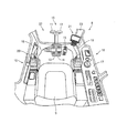
- FIG. 2 is a perspective view showing an internal configuration of the cab 8 based on the first embodiment.
- the cab 8 includes a driver's seat 9, a traveling operation unit 10, an attachment pedal 15, a side window 16, an instrument panel 17, work implement levers 18 and 19, a lock It has a lever 20, a monitor device 21, a front window 22, and a vertical frame 23.
- the driver's seat 9 is provided in the central part of the driver's cab 8.
- the travel operation unit 10 is provided in front of the driver seat 9.
- the traveling operation unit 10 includes traveling levers 11 and 12 and traveling pedals 13 and 14.
- the travel pedals 13 and 14 are movable integrally with the travel levers 11 and 12.
- the lower traveling body 1 moves forward when the operator pushes the traveling levers 11 and 12 forward. Further, the lower traveling body 1 moves backward when the operator pulls the traveling levers 11 and 12 backward.
- the attachment pedal 15 is provided in the vicinity of the traveling operation unit 10.
- the instrument panel 17 is provided in the vicinity of the right side window 16 in FIG.
- Work machine levers 18 and 19 are provided on the left and right sides of the driver's seat 9.
- the work machine levers 18 and 19 are used to move the boom 5 up and down, rotate the arm 6 and the bucket 7, rotate the upper swing body 3, and the like.
- the lock lever 20 is provided in the vicinity of the work machine lever 18.
- the lock lever 20 is for stopping functions such as operation of the work implement 4, turning of the upper revolving structure 3, and traveling of the lower traveling structure 1.
- the movement of the work implement 4 and the like can be locked (restricted) by performing an operation to position the lock lever 20 in the vertical state (here, a pull-down operation of the lock lever).
- the lock lever 20 In a state where the movement of the work implement 4 or the like is locked by the lock lever 20, even if the operator operates the work implement levers 18 and 19, the work implement 4 or the like does not operate.
- the traveling levers 11 and 12 and the traveling pedals 13 and 14 are operated, the lower traveling body 1 does not operate.
- the monitor device 21 is provided below the vertical frame 23 that partitions the front window 22 and the one side window 16 of the cab 8, and displays the engine state, guidance information, warning information, and the like of the work vehicle 101. In addition, the monitor device 21 is provided so as to be able to accept setting instructions regarding various operations of the work vehicle 101.
- the engine state is, for example, the temperature of engine cooling water, the temperature of hydraulic oil, the remaining amount of fuel, and the like.
- the guidance information is, for example, a display that prompts inspection / maintenance of the engine of the work vehicle.
- the various operations include setting of operation mode, setting related to idling stop control, and the like.
- the warning information is information that needs to call attention to the operator.
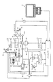
- FIG. 3 is a simplified diagram showing the configuration of the control system for work vehicle 101 based on the first embodiment.
- the control system for the work vehicle 101 includes, as an example, work machine levers 18 and 19, travel levers 11 and 12, a lock lever 20, a monitor device 21, a first hydraulic pump 31A, Second hydraulic pump 31B, swash plate driving device 32, pump controller 33, control valve 34, hydraulic actuator 35, engine 36, governor motor 37, engine controller 38, fuel dial 39, and rotation sensor 40
- control system of the work vehicle 101 includes a radiator 60, a cooling pump 61, an exhaust purification unit 62, a relay connection pipe (mixing pipe) 64, a selective reduction catalyst device 65, an exhaust pipe 66, and a cooling pipe 67. And a temperature sensor 70 and a reducing agent injection device 84.
- the reducing agent injection device 84 includes a reducing agent tank 69, a reducing agent supply pump 82, and a reducing agent injection valve 68.
- the exhaust purification unit 62 includes a diesel oxidation catalyst device 62A and a diesel particulate filter device 62B.
- the first hydraulic pump 31A discharges hydraulic oil used for driving the working machine 4 and the like.
- the second hydraulic pump 31B discharges oil used for generating hydraulic pressure (pilot pressure) according to the operation of the work machine levers 18 and 19 and the travel levers 11 and 12.
- a swash plate driving device 32 is connected to the first hydraulic pump 31A.
- the swash plate driving device 32 is driven based on an instruction from the pump controller 33 to change the inclination angle of the swash plate of the first hydraulic pump 31A.
- a hydraulic actuator 35 is connected to the first hydraulic pump 31A via a control valve 34.
- the hydraulic actuator 35 is a boom cylinder, an arm cylinder, a bucket cylinder, a turning hydraulic motor, a traveling hydraulic motor, or the like.
- the control valve 34 is connected to the work machine lever device 41.
- the work implement lever device 41 outputs a pilot pressure corresponding to the operation direction and / or the operation amount of the work implement levers 18 and 19 and the travel levers 11 and 12 to the control valve 34.
- the control valve 34 controls the hydraulic actuator 35 according to the pilot pressure.
- the work machine levers 18 and 19, the travel levers 11 and 12 and the lock lever 20 are connected to the second hydraulic pump 31B.
- the pressure sensor 47 is connected to the work machine lever device 41.
- the pressure sensor 47 outputs a lever operation signal corresponding to the operation state of the work machine levers 18 and 19 and the travel levers 11 and 12 to the main controller 50.
- the pump controller 33 determines the first hydraulic pump according to the pump absorption torque set according to the work amount, the engine speed set by the fuel dial 39, the actual engine speed, and the like. 31A performs control so as to absorb the best matching torque at each output point of the engine 36.
- the engine 36 has a drive shaft connected to the first hydraulic pump 31A, the second hydraulic pump 31B, and the cooling pump 61.
- the governor motor 37 adjusts the fuel injection amount by the fuel injection device in the engine 36.
- the engine controller 38 controls the operation of the engine 36.
- the engine 36 is a diesel engine as an example.
- the engine speed of the engine 36 is set by the fuel dial 39 or the like, and the actual engine speed is detected by the rotation sensor 40.
- the rotation sensor 40 is connected to the main controller 50.
- the fuel dial 39 is provided with a potentiometer 45.
- the amount of operation of the fuel dial 39 is detected by the potentiometer 45, and a dial command value (also referred to as a dial command value) relating to the rotational speed of the engine 36 is output to the engine controller 38.
- the target rotational speed of the engine 36 is adjusted according to the dial command value of the fuel dial 39.
- the engine controller 38 instructs the governor motor 37 based on the dial command value according to the instruction from the main controller 50, and controls the amount of fuel injected by the fuel injection device to adjust the rotational speed of the engine 36.
- the starter switch 46 is connected to the engine controller 38. When the operator operates the starter switch 46 (set to start), a start signal is output to the engine controller 38 and the engine 36 is started.
- the main controller 50 is a controller that controls the entire work vehicle 101, and includes a CPU (Central Processing Unit), a nonvolatile memory, a timer, and the like.
- the main controller 50 controls the pump controller 33, the engine controller 38, the monitor device 21, the cooling pump 61, and the like.
- the dial command value from the fuel dial 39 and the start signal from the starter switch 46 are also input to the main controller 50 via the engine controller 38.
- the dial command value related to the rotational speed of the engine 36 is input to the main controller 50 via the engine controller 38 will be described, but the present invention is not limited to this method.
- the dial command value can be directly input to the main controller 50.
- the pressure switch 42 is connected to the lock lever 20.
- the pressure switch 42 detects the operation when the lock lever 20 is operated to the lock side, and sends a signal to the valve (solenoid valve) 43.
- the valve 43 shuts off the supply of oil, so that it is possible to stop functions such as operation of the work implement 4, turning of the upper turning body 3, and running of the lower running body 1.
- the pressure switch 42 also sends a similar signal to the main controller 50.
- the main controller 50 detects a signal from the pressure switch 42 and starts control of an idling stop operation described later.
- the main controller 50 detects that the lock lever 20 has been operated to the lock side, and starts control of the idling stop operation.
- the cooling pump 61 supplies cooling water to the circulation path by driving the engine 36.
- the cooling pump 61 operates based on the power from the engine 36 to cool the radiator 60 provided in the engine 36 and the cooling pipe 67 provided in the reducing agent injection device 84.
- the diesel oxidation catalyst device 62A has a function of reducing nitrogen monoxide (NO) among nitrogen oxides (NOx) in the exhaust gas of the engine 36 and increasing nitrogen dioxide (NO 2 ).
- the diesel particulate filter device 62B is a device that processes the exhaust from the engine 36.
- the diesel particulate filter device 62B is configured to collect particulate matter contained in the exhaust of the engine 36 with a filter and incinerate the collected particulate matter.
- the filter is made of ceramic, for example.
- the selective reduction catalyst device 65 is for reducing, for example, nitrogen oxides NOx by hydrolyzing urea water as a reducing agent.
- the selective reduction catalyst device 65 is applied in principle that nitrogen oxide (NOx) is reduced to nitrogen (N 2 ) and water (H 2 O) by chemically reacting with ammonia (NH 3 ). It is a thing.
- the work vehicle 101 is equipped with a reducing agent tank 69 containing, for example, urea water.
- the reducing agent is not limited to urea water, and may be any one that can reduce nitrogen oxide NOx.
- the relay connection pipe (mixing pipe) 64 connects the diesel particulate filter device 62B and the selective reduction catalyst device 65.
- a diesel particulate filter device 62B and a selective reduction catalyst device 65 are connected by a mixing pipe 64.
- a reducing agent is injected and mixed with respect to the exhaust gas that travels from the diesel particulate filter device to the selective reduction catalyst device 65.
- the reducing agent injection device 84 injects the reducing agent (urea water) pumped up from the reducing agent tank 69 by the reducing agent supply pump 82 into the exhaust gas through the reducing agent injection valve 68.
- a cooling pipe which is a part of a cooling water circulation path for suppressing the reducing agent injection device 84 from being maintained at a high temperature by the exhaust gas. 67 is provided.
- the cooling pump 61 supplies cooling water to the cooling pipe 67 to cool the cooling pipe 67.
- the reducing agent injection device 84 including the reducing agent injection valve 68 is cooled via the cooling pipe 67 to which the cooling water is supplied.
- the temperature sensor 70 detects the temperature of the exhaust gas passing through the relay connection pipe (mixing pipe) 64 and outputs it to the main controller 50.
- the exhaust cylinder 66 is connected to the selective reduction catalyst device 65, and is used for discharging the exhaust gas after passing through the selective reduction catalyst device 65 into the atmosphere.
- the engine 36, the reducing agent injection device 84, and the diesel particulate filter device 62B are examples of the “engine”, “injection device”, and “collection device” of the present invention, respectively.
- the cooling pump 61 and the cooling pipe 67 are examples of the “cooling device” in the present invention.
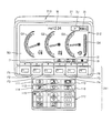
- FIG. 4 is a diagram illustrating the configuration of the monitor device 21 based on the first embodiment.
- the monitor device 21 includes an input unit 211, a display unit 212, and a display control unit 213.
- the input unit 211 receives input of various information.
- the monitor device 21 is connected to the main controller 50, and the input received by the input unit 211 is output to the main controller 50.
- the display unit 212 is realized using a liquid crystal screen or the like.
- the display control unit 213 controls the display content of the display unit 212. Specifically, the display control unit 213 displays information related to the operation of the work vehicle 101 in accordance with an instruction from the main controller 50.
- the information includes engine state information or guidance information, warning information, and the like.
- the input unit 211 will be specifically described.
- the input unit 211 includes a plurality of switches.
- the input unit 211 includes function switches F1 to F6.
- the function switches F1 to F6 are positioned below the display unit 212 and are displayed as “F1” to “F6”, respectively. Icons displayed on the display unit 212 above each switch (for example, guidance icons I1 to I3) ) Is a switch for inputting a signal corresponding to.
- the input unit 211 includes a decel switch 111, an operation mode selection switch 112, a travel speed stage selection switch 113, a buzzer cancellation switch 114, a wiper switch 115, which are provided below the function switches F1 to F6.
- a washer switch 116 and an air conditioner switch 117 are provided.
- the decel switch 111 is a switch for executing decel control for reducing the engine speed of the engine 36 to a predetermined speed after a predetermined time after the work machine levers 18 and 19 return to the neutral position.
- the “neutral position” means that the work implement levers 18 and 19 are not operated (no work state).
- the operation mode selection switch 112 is a switch for selecting an operation mode of the work vehicle 101 from a plurality of operation modes.
- the traveling speed stage selection switch 113 is a switch for selecting the traveling speed stage of the work vehicle 101 from a plurality of traveling speed stages.
- the buzzer cancel switch 114 is a switch for canceling a buzzer sound that is generated when the work vehicle 101 enters a predetermined warning state.
- the wiper switch 115 is a switch for operating a wiper (not shown) provided on the windshield of the cab 8 (see FIG. 2) of the work vehicle 101.
- the washer switch 116 is a switch that operates a washer (not shown) that injects cleaning water onto the windshield.
- the air conditioner switch 117 is a switch for operating various functions of the air conditioner in the cab 8.
- a touch panel of a resistive film type or the like can be applied as the input unit 211.
- the standard screen 301 is generated by the display control unit 213 based on data for displaying a screen stored in advance in a memory (not shown). The same applies to other screens.
- an engine water temperature gauge G1 a hydraulic oil temperature gauge G2, and a fuel level gauge G3 are displayed side by side, and the gauge needles change based on sensor signals from the corresponding sensors.
- a fuel consumption gauge G4 is displayed on the right side of the fuel level gauge G3.
- a clock W is displayed in the center above the display unit 212.
- an operation mode icon IU indicating the set operation mode
- a travel speed stage icon IS indicating the set travel speed stage are displayed.
- the letter “P” is displayed as the operation mode icon IU. This is a display when the operation mode is set to the power mode used in normal excavation work or the like.
- the letter “E” is displayed as the operation mode icon IU.
- an icon including a character string “Hi” is displayed as the traveling speed stage icon IS.
- This icon is displayed when the traveling speed stage is set to high speed.
- an icon including the character string “Lo” is displayed as the traveling speed stage icon IS.
- an icon including the character string “Mi” is displayed as the traveling speed stage icon IS.
- Guidance icons I1 to I3 corresponding to the function switches F4 to F6 are displayed at positions below the standard screen 301 and above the function switches F4 to F6, respectively.
- the guidance icon I1 is an icon that means switching the screen displayed on the display unit 212 to the camera screen.
- the camera screen is a screen that is installed on the exterior of the work vehicle 101 and outputs an image signal acquired by a CCD camera or the like (not shown) that captures the outside of the work vehicle 101.
- the guidance icon I2 is an icon that means switching the display of the clock W to the display of the service meter.
- the guidance icon I3 is an icon that means switching the screen displayed on the display unit 212 to the user mode screen. Therefore, for example, when the function switch F4 corresponding to the guidance icon I1 is pressed, the screen displayed on the display unit 212 is switched to the camera screen.
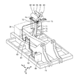
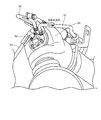
- FIG. 5 is a diagram illustrating a configuration for supplying urea to the selective reduction catalyst device of the exhaust treatment unit based on the first embodiment.
- engine 36 and the exhaust treatment unit are supported by body frame 75 independently of each other.
- the structure of the support for supporting the exhaust treatment unit on the frame includes two plate plates 71, four vertical frames (column members) 72, a horizontal frame 73, and a bracket 74. ing.
- Each of the two plate plates 71 has a flat plate shape and is attached to the vehicle body frame 75.
- Each of the four vertical frames 72 has a pillar shape and is attached to the plate plate 71.
- Each of the four vertical frames 72 extends upward from an attachment position to the plate plate 71.
- the horizontal frame 73 is attached to the vertical frame 72.
- the horizontal frame 73 is a part for supporting the exhaust purification unit 62 and the selective reduction catalyst device 65.
- the bracket 74 has a flat plate shape. It is attached to the horizontal frame 73.
- relay connection pipe (mixing pipe) 64 of the exhaust treatment unit and the reducing agent tank 69 are connected by a urea water pipe (reducing agent pipe).
- the selective reduction catalyst device 65 is for selectively reducing nitrogen oxides NOx using, for example, ammonia obtained by hydrolyzing urea water. For this reason, a device for supplying urea water to the selective catalytic reduction device 65 is required.
- the reducing agent injection device 84 mainly includes a reducing agent injection valve 68, a reducing agent tank 69, a reducing agent supply pump 82, and a reducing agent pipe 83.
- the reducing agent tank 69 is configured to store urea water.
- the reducing agent tank 69 is disposed, for example, outside the engine room, and is supported by the vehicle body frame 75.
- the reducing agent pipe 83 connects the reducing agent tank 69 and the mixing pipe 64. With this reducing agent pipe 83, the urea water stored in the reducing agent tank 69 can be guided to the mixing pipe 64.
- the reducing agent supply pump 82 is arranged in the middle of the path of the reducing agent pipe 83.
- the reducing agent supply pump 82 plays a role of sending urea water from the reducing agent tank 69 to the mixing pipe 64 through the reducing agent pipe 83.
- urea water stored in the reducing agent tank 69 is injected and supplied from the reducing agent injection valve 68 to the mixing pipe 64 through the reducing agent pipe 83. Is done.
- the reducing agent pipe 83 is connected to the mixing pipe 64 from the same side in the longitudinal direction (X direction) (front side in the figure).
- a connecting portion of the reducing agent pipe 83 to the mixing pipe 64 is upstream of the exhaust path in the mixing pipe 64.
- the urea water injected and supplied to the mixing pipe 64 is evenly mixed with the exhaust gas from the upstream side to the downstream side in the mixing pipe 64.
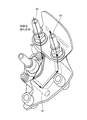
- FIG. 6 is a diagram illustrating a state around the reducing agent injection valve 68 according to the first embodiment.
- a reducing agent injection valve 68 connected to a reducing agent pipe 83 is attached to the upstream side of the exhaust path in the mixing pipe 64.
- FIG. 7 is a view for explaining the internal state of the reducing agent injection valve 68 based on the first embodiment.
- a cooling pipe 67 through which cooling water flows is provided inside the reducing agent injection valve 68.
- the cooling water pipe 92, the cooling pipe 67, and the cooling water pipe 93 By supplying cooling water through the cooling water pipe 92, the cooling pipe 67, and the cooling water pipe 93, the reducing agent injection valve 68 is cooled.
- FIG. 8 is a functional block diagram illustrating the main controller 50 of the control system for the work vehicle 101 based on the first embodiment.
- a monitor device 21 As shown in FIG. 8, the relationship between the main controller 50 and other peripheral devices is shown.
- a monitor device 21 As shown in FIG. 8, the relationship between the main controller 50 and other peripheral devices is shown.
- a monitor device 21 an engine 36, a governor motor 37, an engine controller 38, a fuel dial 39, a potentiometer 45, a starter switch 46, and a temperature sensor 70 are shown as peripheral devices.
- the main controller 50 includes a high temperature state determination unit 52, a stop determination unit 54, a memory 55, a stop prohibition unit 56, a counter 58, a warning unit 53, and a communication unit 95.
- the high temperature state determination unit 52 determines whether or not the reducing agent injection device 84 is in a high temperature state based on the temperature detected by the temperature sensor 70. When the high temperature state determination unit 52 determines that the reducing agent injection device 84 is in a high temperature state, the high temperature state determination unit 52 sets a high temperature flag stored in a predetermined area of the memory 55 to “ON”. On the other hand, when the high temperature state determination unit 52 determines that the reducing agent injection device 84 is not in the high temperature state based on the temperature detected by the temperature sensor 70, the high temperature state determination unit 52 sets the high temperature flag stored in the predetermined area of the memory 55 to “ Set to “Off”.
- the high temperature flag is “1” and the high temperature flag is “off” is set to “0” as an example. Note that the high temperature flag may be set to “0” for “on”, and the high temperature flag may be set to “1” for “off”.
- the stop determination unit 54 determines whether or not the engine 36 has stopped when the reducing agent injection device 84 is in a high temperature state.
- the stop determination unit 54 determines whether or not the engine 36 has stopped while the high temperature flag stored in the predetermined area of the memory 55 is “on”.
- the stop determination unit 54 instructs the counter 58 when determining that the engine 36 has stopped when the reducing agent injection device 84 is in a high temperature state.
- the stop determination unit 54 resets the high temperature flag stored in a predetermined area of the memory 55. Specifically, the stop determination unit 54 sets the high temperature flag to “off”.
- the counter 58 increments the count value in accordance with the instruction from the stop determination unit 54.
- the warning unit 53 instructs the monitor device 21 to notify a warning when a predetermined value (first predetermined value) is exceeded based on the count value of the counter 58. Further, when the warning unit 53 exceeds a predetermined value (second predetermined value) based on the count value of the counter 58, the warning unit 53 notifies the stop prohibition unit 56 to that effect.
- the display control unit 213 of the monitor device 21 displays predetermined warning information on the display unit 212 in accordance with an instruction from the warning unit 53.
- the communication unit 95 transmits the count value of the counter 58 to the management server according to the instruction from the warning unit 53.
- the stop prohibition unit 56 instructs the engine controller 38 not to stop the engine 36 based on the instruction from the warning unit 53 and the state of the high temperature flag set in a predetermined area of the memory 55.
- the engine controller 38 prohibits the output of the engine stop signal to the governor motor 37 in accordance with the instruction from the stop prohibiting unit 56. Thereby, it is possible to prohibit the stop of the engine 36 in accordance with an instruction from the stop prohibiting unit 56. For example, even when the operator operates the starter switch 46 to turn it off, the engine controller 38 does not stop the engine 36 if there is an instruction from the stop prohibition unit 56.
- the stop prohibition unit 56 continuously outputs an instruction to prohibit the stop when the high temperature flag is “ON”. On the other hand, when the high temperature flag is “OFF”, the instruction to prohibit the stop is terminated.
- the engine controller 38 receives an instruction for prohibiting the stop of the engine 36 from the stop prohibition unit 56, then prohibits the stop of the engine 36, and ends the instruction for prohibiting the stop of the engine 36 from the stop prohibition unit 56. The engine 36 is stopped.
- the high temperature state determination unit 52, the stop determination unit 54, the counter 58, the warning unit 53, and the communication unit 95 are the “determination unit”, “stop determination unit”, “counter”, “warning unit”, and “warning unit” of the present invention, respectively. It is an example of a "communication part.”
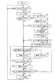
- FIG. 9 is a flowchart illustrating a warning function of the control system for work vehicle 101 based on the first embodiment.
- step S1 it is determined whether or not the starter switch 46 is “ON” (step S1). Specifically, the engine controller 38 receives an operation instruction from the starter switch 46 and determines whether or not it is turned “on”.
- step S2 If it is determined that the starter switch 46 is “ON”, the engine 36 is started (step S2). Specifically, the engine controller 38 instructs the governor motor 37 to start the engine 36. Further, the engine controller 38 outputs information indicating that the engine 36 has been started to the stop determination unit 54 of the main controller 50.
- step S3 it is determined whether or not the high temperature flag is “ON” (step S3).
- the stop determination unit 54 refers to the memory 55 and determines whether or not the high temperature flag is set to “ON”.
- step S3 If it is determined in step S3 that the high temperature flag is set to “ON” (YES in step S3), the counter is incremented (step S4). Specifically, the stop determination unit 54 refers to the memory 55 and instructs the counter 58 when determining that the high temperature flag is set to “ON”. Thereby, the counter 58 increments the count value.
- step S5 the high temperature flag is reset.
- the stop determination unit 54 refers to the memory 55 and resets the state where the high temperature flag is “on” and sets it to “off”.
- step S6 it is determined whether or not the counter number exceeds a first predetermined value. Specifically, the warning unit 53 determines whether or not the count value of the counter 58 exceeds a predetermined value (first predetermined value). For example, it is possible to set “150” as the predetermined value (first predetermined value).
- step S6 If it is determined in step S6 that the count value does not exceed the first predetermined value (NO in step S6), the process proceeds to step S10.
- step S6 when it is determined in step S6 that the count value exceeds the first predetermined value (YES in step S6), warning information is notified (step S7). Specifically, the warning unit 53 instructs the monitor device 21 to notify the warning, and the display control unit 213 of the monitor device 21 displays predetermined warning information on the display unit 212.
- step S8 it is determined whether or not the count value exceeds a second predetermined value. Specifically, the warning unit 53 determines whether or not the count value of the counter 58 exceeds a predetermined value (second predetermined value). For example, it is possible to set “200” as the predetermined value (second predetermined value).
- step S8 When it is determined in step S8 that the count value does not exceed the second predetermined value (NO in step S8), the process proceeds to step S10.
- step S8 when it is determined in step S8 that the count value exceeds the second predetermined value (YES in step S8), the engine stop prohibition determination flag is set to “on” (step S9). Specifically, when the warning unit 53 determines that the count value exceeds the second predetermined value, the warning unit 53 sets the engine stop prohibition determination flag stored in the predetermined area of the memory 55 to “ON”. . The engine stop prohibition determination flag is used in a process for prohibiting the engine 36 from being stopped when the engine 36 is instructed to stop. This point will be described later. Then, the process proceeds to the next step S10.
- step S3 determines whether the high temperature flag is not set to “ON” (NO in step S3). If it is determined in step S3 that the high temperature flag is not set to “ON” (NO in step S3), the process of steps S4 to S9 is skipped and the process proceeds to step S10.
- step S10 it is determined whether or not the reducing agent injection device is in a high temperature state. Specifically, the high temperature state determination unit 52 determines whether or not the reducing agent injection device 84 is in a high temperature state based on the temperature detected by the temperature sensor 70.
- step S10 If it is determined in step S10 that the reducing agent injection device 84 is in a high temperature state (YES in step S10), the high temperature flag is set to “ON” (step S11). Specifically, when the high temperature state determination unit 52 determines that the reducing agent injection device 84 is in a high temperature state, the high temperature state determination unit 52 sets a high temperature flag stored in a predetermined area of the memory 55 to “ON”.
- step S10 determines whether the reducing agent injection device 84 is in a high temperature state (NO in step S10). If it is determined in step S10 that the reducing agent injection device 84 is not in a high temperature state (NO in step S10), the high temperature flag is reset (step S16). Specifically, when it is determined that the reducing agent injection device 84 is not in a high temperature state, the high temperature state determination unit 52 sets a high temperature flag stored in a predetermined area of the memory 55 to “off”.
- step S12 it is determined whether there is an engine stop instruction. Specifically, the engine controller 38 receives an operation instruction from the starter switch 46 and determines whether or not it has been turned “off”. If the engine controller 38 receives an operation instruction from the starter switch 46 and determines that the engine controller 38 has been turned off, the engine controller 38 notifies the stop prohibition unit 56 that there has been an instruction to stop the engine. The stop prohibition unit 56 determines whether a notification input indicating that there has been an instruction to stop the engine from the engine controller 38 has been received.
- step S12 If it is determined in step S12 that there is no engine stop instruction, the process returns to step S10. If it is determined that there is an engine stop instruction (YES in step S12), it is determined whether or not the high temperature flag is “ON”. (Step S13). Specifically, the stop prohibition unit 56 determines whether or not the stop of the engine 36 is prohibited in accordance with a notification input indicating that there has been an instruction to stop the engine from the engine controller 38. The stop prohibition unit 56 determines whether or not the high temperature flag stored in the predetermined area of the memory 55 is set to “ON”.
- step S13 If it is determined in step S13 that the high temperature flag is “ON” (YES in step S13), it is determined whether the engine stop prohibition determination flag is “ON” (step S14). Specifically, the stop prohibition unit 56 determines whether an engine stop prohibition determination flag stored in a predetermined area of the memory 55 is “ON”.
- step S14 If it is determined in step S14 that the engine stop prohibition determination flag is “ON” (YES in step S14), the process returns to step S10 and the engine 36 is not stopped. Specifically, the stop prohibiting unit 56 determines that the high temperature flag stored in a predetermined area of the memory 55 is “ON” and the engine stop prohibition determination flag is “ON”, and then the engine 36 Is instructed not to stop the engine controller 38. Thereby, the engine controller 38 processes the engine stop instruction as invalid.
- step S13 when it is determined in step S13 that the high temperature flag is not “ON” (NO in step S13), the engine is stopped (step S15). Specifically, the stop prohibition unit 56 notifies the engine controller 38 that the stop of the engine 36 is not prohibited, and the engine controller 38 instructs the governor motor 37 to stop the engine 36. . As a result, the engine 36 stops.
- step S14 If it is determined in step S14 that the engine stop prohibition determination flag is not “ON” (NO in step S14), the engine is stopped (step S15). Specifically, the stop prohibition unit 56 notifies the engine controller 38 that the stop of the engine 36 is not prohibited, and the engine controller 38 instructs the governor motor 37 to stop the engine 36. . As a result, the engine 36 stops.
- the stop prohibition unit 56 stops the engine 36 when it is determined that the high temperature flag indicating the temperature state of the reducing agent injection device 84 is “ON” and the engine stop prohibition determination flag is “ON”. It is possible to prevent this. Then, when the high temperature flag indicating the temperature state of the reducing agent injection device 84 is turned “off” (when the temperature of the reducing agent injection device 84 has dropped and has disappeared in the high temperature state), the stop prohibition unit 56 Ends the instruction to prohibit the stop. Thereby, the engine 36 can be stopped. Therefore, it is possible to suppress the burden on the reducing agent injection device 84 by preventing the engine 36 from stopping when the reducing agent injection device 84 is in a high temperature state.
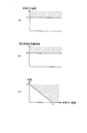
- FIG. 10 is a diagram for explaining the determination of the high temperature state in the high temperature state determination unit 52 based on the first embodiment.
- the high temperature state determination unit 52 determines that the reducing agent injection device 84 is in a high temperature state when the exhaust gas temperature detected by the temperature sensor 70 is equal to or higher than a predetermined temperature X1.
- the high temperature state can be defined in accordance with the relationship with the heat resistant temperature determined based on the material and characteristics of the components of the reducing agent injection device 84. For example, as an example, when the temperature is in the vicinity of the heat resistant temperature, the high temperature state can be achieved.
- the high temperature state determination unit 52 sets the high temperature flag of the memory 55 to “ON”.
- the high temperature state determination unit 52 indirectly detects the temperature of the reducing agent injection device 84 by detecting the exhaust gas temperature near the exhaust port discharged from the diesel particulate filter device 62B by the temperature sensor 70. A case where the measurement is performed and it is determined that the reducing agent injection device 84 is in a high temperature state will be described.
- the present invention is not limited to this method, and the state of the reducing agent injection device 84 may be determined by another method.
- the temperature sensor 70 may be attached to the reducing agent injection valve 68 and the temperature of the reducing agent injection device 84 may be directly measured to determine whether or not the reducing agent injection device 84 is in a high temperature state. .
- the reducing agent injection device 84 determines whether or not the reducing agent injection device 84 is in a high temperature state based on the relationship between the exhaust gas temperature and the coolant temperature.
- the case where the exhaust gas temperature at which the reducing agent injection device 84 is determined to be in a high temperature state increases as the coolant temperature decreases.
- the present invention is not limited to this, and the exhaust in the vicinity of the inlet of the selective reduction catalyst device 65 is described.
- the gas temperature may be detected to determine whether or not the reducing agent injection device 84 is in a high temperature state.
- the method of determining whether or not the reducing agent injection device 84 is in a high temperature state based on the temperature detected by the temperature sensor 70 has been described.
- the reducing agent injection is not performed without providing the temperature sensor 70.
- the exhaust gas temperature is also related to the engine output.
- the rotation sensor 40 that measures the output rotation speed of the engine may be used to determine whether or not the reducing agent injection device 84 is in a high temperature state based on the measurement result measured by the rotation sensor 40.
- the engine output speed is estimated based on the output command value (rotation command) output from the potentiometer 45 of the fuel dial 39 instead of the engine output speed measured by the rotation sensor 40, and the estimation result Based on the above, it may be determined whether the temperature of the reducing agent injection device 84 according to the exhaust gas temperature is in a high temperature state.
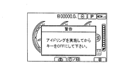
- FIG. 11 is a diagram illustrating an example of warning information displayed on the monitor device 21 based on the first embodiment.
- warning information is notified to the display unit 212 of the monitor device 21 as shown in FIG. Specifically, a warning message “Please turn off the key after idling” is displayed.
- the warning unit 53 notifies warning information when the count value of the counter 58 exceeds a predetermined value (first predetermined value).
- the reducing agent injection device 84 By notifying the operator of the warning information, when the engine 36 is stopped for the operator, the reducing agent injection device 84 is not stopped when the reducing agent injection device 84 is in a high temperature state. When the engine is not in a high temperature state, it is possible to prompt the engine 36 to stop. For this reason, it is possible to protect the equipment of the reducing agent injection device 84.
- the counter 58 counts the number of times the engine 36 has stopped when the reducing agent injection device 84 is in a high temperature state, and when the count value exceeds a predetermined value (first predetermined value), The warning information is notified to the operator. Therefore, it is possible to accurately protect the degree of burden on the reducing agent injection apparatus 84 and to protect the equipment of the reducing agent injection apparatus 84 by notifying the operator of warning information according to the degree of burden on the reducing agent injection apparatus 84. It becomes possible.
- the predetermined value (first predetermined value) is set in consideration of the degree of burden applied to the reducing agent injection device 84 when the engine 36 is stopped when the reducing agent injection device 84 is in a high temperature state. If it is a person skilled in the art, it can be appropriately set to an appropriate value. An appropriate value may be set by simulation. The same applies to the predetermined value (second predetermined value).
- the present invention is not limited to this, and the message may be output by voice, or an icon associated with the message Can be displayed to notify the operator of warning information. Further, as the notification method, it is possible to vibrate the monitor device 21 using the vibration function, or to perform processing such as blinking the display of the display unit 212 using the light emitting function.
- the content of the message is not limited to the above, and any message may be used as long as it prompts the engine 36 to stop when the reducing agent injection device 84 is not in a high temperature state. It is also possible to notify information such as maintenance or maintenance inspection.
- the warning information is notified to the display unit 212 when the count value exceeds a predetermined value (first predetermined value).
- the start of the engine 36 means not only the timing at which the engine 36 is started but also the period from the start to the elapse of a predetermined period.
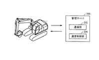
- FIG. 12 is a diagram illustrating the relationship between the work vehicle 101 and the management server 200 based on the first embodiment.
- the management server 200 is located away from the work vehicle 101 and is communicable with the work vehicle 101.
- the management server 200 includes a communication unit 202 and a communication control unit 204.
- Communication unit 202 communicates with communication unit 95 of main controller 50 of work vehicle 101 via a network (not shown).
- the communication unit 202 communicates with the communication unit 95 and receives information related to the counter 58 of the main controller 50.
- the communication control unit 204 executes predetermined information processing via the communication unit 202. As the predetermined information processing, analysis processing or the like based on the received information about the counter 58 is executed.
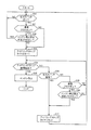
- FIG. 13 is a flowchart illustrating a warning function of the control system for work vehicle 101 based on the modification of the first embodiment.
- step S7A is further added. Since other configurations are the same as those described above, detailed description thereof will not be repeated.
- step S7 If it is determined in step S7 that the count value exceeds the first predetermined value (YES in step S6), warning information is notified (step S7).
- the count value is transmitted (step S7A). Specifically, the warning unit 53 instructs the communication unit 95 to transmit the count value of the counter 58 to the management server 200.
- the communication unit 95 transmits to the communication unit 202 of the management server 200 according to the instruction.
- step S8 it is determined whether or not the count value exceeds a second predetermined value (step S8). Since the subsequent processing is the same, detailed description thereof will not be repeated.
- the work vehicle 101 can transmit the count value to the management server 200 when the count value exceeds the first predetermined value. It is possible to accurately grasp the degree of burden on the injection device 84.
- the communication control unit 204 an analysis process based on the received information (count value) about the counter 58 is executed, the degree of burden is analyzed in more detail, and the work vehicle 101 from the management server 200 side is analyzed.
- other warning information may be notified via the communication unit 202.
- the management server 200 acquires information on the counter 58 from each work vehicle 101, thereby varying the degree of burden on the reducing agent injection device 84 or the state of the burden.
- the information obtained based on the analysis result can be used as information for protecting the reducing agent injection device 84.
- the communication unit 95 has been described with respect to the method of transmitting the count value to the management server 200 when the count value exceeds the first predetermined value.
- the communication unit 95 may transmit information regarding the counter 58 to the management server 200 accordingly.
- the management server 200 can recognize the count value of the counter 58 in synchronization with the work vehicle 101. Therefore, the management server 200 determines whether or not the count value exceeds the first predetermined value, and if it is determined that the count value exceeds the first predetermined value, the management server 200 communicates.
- the warning information may be transmitted to the work vehicle 101 via the unit 202 and displayed.
- warning information display determination or the like is executed on the management server 200 side, so it is necessary to reduce the processing load on the work vehicle 101 and to change the content of message display and the like by version upgrade, function expansion, and the like. Even if it exists, there exists an advantage that it can respond easily.
- the stop prohibiting unit 56 indicates that the high temperature flag indicating the temperature state of the reducing agent injection device 84 is “ON” and the engine stop prohibition determination flag is set. A method for preventing the engine 36 from stopping when it is determined to be “on” has been described.
- the stop of the engine 36 is not based only on an instruction accompanying an operator's key operation, and the engine 36 may be stopped depending on other states.
- the idling stop function is a function that automatically stops the engine when the idling state of the work vehicle continues for a predetermined time.
- the idling state means a state where the work vehicle stands by while the engine is operating. There is a possibility that the engine 36 is stopped by the idling stop function.
- FIG. 14 is a functional block diagram illustrating a main controller 50A of the control system for work vehicle 101 based on the second embodiment.
- the main controller 50 ⁇ / b> A further includes an operation state detection unit 94 and an idling stop control unit 51, as compared with the main controller 50. Moreover, the case where the pressure switch 42 and the lock lever 20 are further provided as another peripheral device is shown.
- the pressure switch 42 is connected to the lock lever 42 and detects the operation when the lock lever 20 is operated to the lock side.
- the operation state detection unit 94 detects the state of the pressure switch 42.
- the idling stop control unit 51 controls an idling stop operation.
- the idling stop control unit 51 includes an idling stop timer 59 and an idling stop execution unit 57.
- the idling stop execution unit 57 outputs an engine stop signal to the engine controller 38 so as to execute an idling stop operation for stopping the engine 36 when a predetermined condition is satisfied.
- the “idling stop operation” means an operation for stopping the engine 36 in a state where the work vehicle is on standby while the engine 36 is operating.
- This predetermined condition is an execution condition for executing the “idling stop operation”, and mainly means a condition relating to a predetermined time during which the idling state of the work vehicle continues.
- the “predetermined time” is also referred to as an idling stop time.
- the idling stop execution unit 57 operates in accordance with an instruction from the operation state detection unit 94, refers to the memory 55 in accordance with an instruction from the operation state detection unit 94, and performs idling based on the states of the high temperature flag and the engine stop prohibition determination flag.
- the stop timer 59 is operated.
- the idling stop timer 59 is a timer that counts time according to an instruction from the idling stop execution unit 57. Then, the count result is output to the idling stop execution unit 57. The idling stop execution unit 57 determines whether or not the idling stop time has elapsed based on the count result (timer value) counted by the idling stop timer 59. Output to the controller 38.
- the engine controller 38 receives the engine stop signal from the idling stop execution unit 57 and instructs the governor motor 37 to stop the engine 36.
- the idling stop execution unit 57 in this example does not operate the idling stop timer 59 when the high temperature flag is “ON” and the engine stop prohibition determination flag is “ON”. Thereby, it is possible not to start the idling stop operation.
- the idling stop execution unit 57 is an example of the “idling stop execution unit” in the present invention.
- FIG. 15 is a flowchart of the idling stop control process of the idling stop control unit 51 based on the second embodiment.
- the idling stop control unit 51 determines whether or not the lock lever 20 is operated to the lock side and the pressure switch 42 is turned on (step S30). Specifically, the operation state detection unit 94 detects that the lock lever 20 is operated to the lock side and the pressure switch 42 is turned on, and outputs it to the idling stop execution unit 57. The idling stop execution unit 57 determines that the pressure switch 42 is turned on based on the detection signal input from the operation state detection unit 94.
- step S30 determines that the pressure switch 42 is not turned on (NO in step S30)
- the idling stop control unit 51 returns to step S30 and determines that the pressure switch 42 is turned on (ON) ( If YES in step S30, it is determined whether the high temperature flag is “ON” (step S31).
- the idling stop execution unit 57 determines whether or not the high temperature flag stored in the memory 55 is “ON”.
- “ON” or “OFF” of the high temperature flag stored in the memory 55 is set by the high temperature state determination unit 52 based on the temperature detected by the temperature sensor 70 as described above. Is possible.
- the high temperature state determination unit 52 determines that the reducing agent injection device 84 is in a high temperature state
- the high temperature state stored in a predetermined area of the memory 55 is set to “on”, and the high temperature state If it is determined that it is not, the high temperature flag is set to “off”.
- step S31 when the idling stop control unit 51 determines that the high temperature flag is “ON” (YES in step S31), next, it is determined whether or not the engine stop prohibition determination flag is “ON”. Judgment is made (step S32).
- the idling stop execution unit 57 refers to the memory 55 and determines whether or not the engine stop prohibition determination flag stored in the memory 55 is “ON”.
- “ON” of the engine stop prohibition determination flag stored in the memory 55 is set by the warning unit 53 based on the count value of the counter 58 as described above.
- the warning unit 53 determines that the count value of the counter 58 exceeds the second predetermined value, the warning unit 53 sets the engine stop prohibition determination flag stored in the predetermined area of the memory 55 to “ON”. Set.
- step S32 when the idling stop control unit 51 determines that the engine stop prohibition determination flag is “on” (YES in step S32), the idling stop timer is not started (started), and the process returns to step S30. .
- the high temperature flag is “on” and the engine stop prohibition determination flag is “on”, the idling stop operation is not executed.
- the idling stop control unit 51 does not execute the idling stop operation when the reducing agent injection device 84 is in a high temperature state and the engine stop prohibition determination flag is “ON”.
- the engine 36 of the work vehicle 101 is not automatically stopped by the idling stop function, and the reductant injection device 84 is suppressed from being stopped in a high temperature state, so that the equipment of the reductant injection device 84 can be protected. It is.
- step S31 the idling stop control unit 51 determines that the high temperature flag is not “ON” (NO in step S31), or determines that the engine stop prohibition determination flag is not “ON” in step S32 (step S31).
- NO in S32 the idling stop timer 59 is started (started) (step S33). Specifically, the idling stop execution unit 57 instructs the idling stop timer 59 to count the time. Then, the idling stop timer 59 outputs the counted timer value to the idling stop execution unit 57.
- the idling stop control unit 51 determines whether or not the idling stop time has elapsed (step S34). Specifically, the idling stop execution unit 57 determines whether or not the time counted by the idling stop timer 59 has exceeded the idling stop time.
- step S34 when it is determined that the idling stop time has elapsed (YES in step S34), the idling stop control unit 51 stops the engine 36 (step S35). Specifically, the idling stop execution unit 57 outputs an engine stop signal to the engine controller 38. As a result, the engine controller 38 instructs the governor motor 37 to stop the engine 36.
- step S34 determines whether or not the pressure switch 42 is released (OFF) (step S34).
- step S34 determines whether or not the pressure switch 42 is released (OFF) (step S34).
- step S34 determines whether or not the pressure switch 42 is released (OFF) (step S34).
- step S34 determines whether or not the pressure switch 42 is released (OFF) (step S34).
- step S36 the operation state detection unit 94 detects that the pressure switch 42 has been released (OFF), and sends a detection signal indicating that the pressure switch 42 has been released (OFF) to the idling stop execution unit 57. Output.
- the idling stop execution unit 57 determines that the pressure switch 42 has been released based on the input of the detection signal from the operation state detection unit 94.
- step S36 when it is determined that the pressure switch 42 has been released (OFF) (YES in step S36), the idling stop control unit 51 resets the idling stop timer 59 (step S37). Specifically, the idling stop execution unit 57 stops counting the time with respect to the idling stop timer 59 based on the input of the detection signal and resets the count value.
- step S30 the idling stop control part 51 waits until the pressure switch 42 turns on again (ON).
- step S36 when it is determined in step S36 that the pressure switch 42 is not released (OFF) (NO in step S36), the idling stop control unit 51 determines whether or not the high temperature flag is “ON” (step S36). Step S38). Specifically, the idling stop execution unit 57 determines whether or not the high temperature flag stored in the memory 55 is “ON”.
- step S38 when the idling stop control unit 51 determines that the high temperature flag is “ON” (YES in step S38), it next determines whether the engine stop prohibition determination flag is “ON”. Judgment is made (step S39). Specifically, the idling stop execution unit 57 refers to the memory 55 and determines whether or not the engine stop prohibition determination flag stored in the memory 55 is “ON”.
- step S39 the idling stop control unit 51 resets the idling stop timer 59 when it is determined that the engine stop prohibition determination flag is “ON” (YES in step S39) (step S37). Specifically, the idling stop execution unit 57 stops counting the time with respect to the idling stop timer 59 based on the input of the detection signal and resets the count value.
- step S30 returns to step S30 and the idling stop control part 51 repeats said process again.
- step S38 determines in step S38 that the high temperature flag is not “ON” (NO in step S38) or in step S39, the engine stop prohibition determination flag is determined not to be “ON” (step S39). If NO in S39, the process returns to step S34 and waits until the idling stop time has elapsed.
- step S34 when it is determined that the idling stop time has elapsed (YES in step S34), the idling stop control unit 51 stops the engine 36 (step S35). Specifically, the idling stop execution unit 57 outputs an engine stop signal to the engine controller 38. As a result, the engine controller 38 instructs the governor motor 37 to stop the engine 36.
- the idling stop control part 51 complete
- the idling stop function is disabled. It is possible to prevent the engine 36 from automatically stopping. It is possible to stop the engine 36 when the temperature of the reducing agent injection device 84 is lowered and disappears in a high temperature state (a state where the high temperature flag is “off”). As a result, the burden on the reducing agent injection device 84 can be suppressed.
- a hydraulic excavator has been described as an example of a work vehicle.
- the present invention can also be applied to a work vehicle such as a bulldozer or a wheel loader, and is a working machine provided with an engine 36. It can be applied to anything.
Abstract
Description
上記によれば、エンジンからの動力に基づいて冷却装置が動作するためエンジンと連携して冷却装置を簡易に制御することが可能である。
上記によれば、エンジンの始動の際に警告を通知することにより効果的に警告を通知することが可能である。
(第1実施形態)
<全体構成>
図1は、第1実施形態に基づく作業車両101の外観を説明する図である。
図2は、第1実施形態に基づく運転室8の内部構成を示す斜視図である。
図3は、第1実施形態に基づく作業車両101の制御システムの構成を示す簡略図である。
次に、モニタ装置21の構成を説明する。
図8は、第1実施形態に基づく作業車両101の制御システムのメインコントローラ50を説明する機能ブロック図である。
図9は、第1実施形態に基づく作業車両101の制御システムの警告機能を説明するフロー図である。
また、ステップS14において、エンジン停止禁止判定フラグが「オン」で無いと判定した場合(ステップS14においてNO)には、エンジンを停止する(ステップS15)。具体的には、停止禁止部56は、エンジンコントローラ38に対してエンジン36の停止が禁止されていない旨を通知し、エンジンコントローラ38は、ガバナモータ37に対してエンジン36を停止するように指示する。これによりエンジン36は停止する。
したがって、停止禁止部56は、還元剤噴射装置84の温度状態を示す高温フラグが「オン」で、かつエンジン停止禁止判定フラグが「オン」であると判定される場合には、エンジン36が停止することを防止することが可能である。そして、停止禁止部56は、還元剤噴射装置84の温度状態を示す高温フラグが「オフ」となった場合(還元剤噴射装置84の温度が下がって高温状態で無くなった場合)に、エンジン36の停止を禁止する指示を終了する。これにより、エンジン36を停止することが可能である。したがって、還元剤噴射装置84が高温状態でエンジン36が停止することを防止することにより還元剤噴射装置84に対する負担を抑制することが可能である。
本例においては、高温状態判断部52は、温度センサ70によるディーゼル微粒子捕集フィルター装置62Bから排出された排出口付近の排気ガス温度を検出することにより間接的に還元剤噴射装置84の温度を測定して、還元剤噴射装置84が高温状態であることを判定する場合について説明するが、当該方式に限られず、別の方式により還元剤噴射装置84の状態を判断するようにしても良い。
図11は、第1実施形態に基づくモニタ装置21に表示される警告情報の一例を説明する図である。
<管理サーバ>
図12は、第1実施形態に基づく作業車両101と管理サーバ200との関係を説明する図である。
通信部202は、ネットワーク(図示せず)を介して作業車両101のメインコントローラ50の通信部95と通信する。本例においては、一例として通信部202は、通信部95と通信して、メインコントローラ50のカウンタ58に関する情報を受信する。
図13は、第1実施形態の変形例に基づく作業車両101の制御システムの警告機能を説明するフロー図である。
上記の第1実施形態においては、エンジン36の停止指示があった場合に停止禁止部56は、還元剤噴射装置84の温度状態を示す高温フラグが「オン」で、かつエンジン停止禁止判定フラグが「オン」であると判定される場合には、エンジン36が停止することを防止する方式について説明した。
図14は、第2実施形態に基づく作業車両101の制御システムのメインコントローラ50Aを説明する機能ブロック図である。
アイドリングストップ制御部51は、アイドリングストップ動作を制御する。
図15は、第2実施形態に基づくアイドリングストップ制御部51のアイドリングストップ制御処理のフロー図である。
一方、ステップS34において、アイドリングストップ制御部51は、アイドリングストップ時間が経過していないと判断した場合(ステップS34においてNO)には、圧力スイッチ42が解除(OFF)されたかどうかを判断する(ステップS36)。具体的には、操作状態検出部94は、圧力スイッチ42が解除(OFF)されたことを検出して、アイドリングストップ実行部57に圧力スイッチ42が解除(OFF)されたことを示す検出信号を出力する。そして、アイドリングストップ実行部57は、操作状態検出部94から当該検出信号の入力に基づいて圧力スイッチ42が解除されたと判断する。
当該処理、還元剤噴射装置84の温度状態を示す高温フラグが「オン」で、かつエンジン停止禁止判定フラグが「オン」であると判定される場合には、アイドリングストップ機能を無効にすることにより、エンジン36が自動的に停止することを防止することが可能である。還元剤噴射装置84の温度が下がって高温状態で無くなった場合(高温フラグが「オフ」の状態)にエンジン36を停止することが可能である。これにより還元剤噴射装置84に対する負担を抑制することが可能である。
Claims (7)
- エンジンと、
前記エンジンから排出される排気ガスに対して還元剤を噴射する噴射装置と、
前記噴射装置の温度が高温状態であるか否かを判断する判断部と、
前記判断部の判断結果として前記噴射装置が高温状態であると判断される場合に前記エンジンが停止したか否かを判定する停止判定部と、
前記停止判定部の判定結果に基づいて、前記噴射装置が高温状態であると判断される場合の前記エンジンの停止回数をカウントするカウンタと、
前記カウンタのカウント値が第1の所定値を超えた場合に前記エンジンの停止に関して警告を通知する警告部とを備える、作業車両。 - 前記噴射装置の上流側に設けられた粒子状物質を捕集する捕集装置をさらに備え、
前記判断部は、前記捕集装置を通過した排気ガスの温度および前記噴射装置の温度の少なくともいずれか一方に基づいて前記噴射装置が高温状態であるか否かを判断する、請求項1記載の作業車両。 - 前記エンジンの作動中に前記噴射装置を冷却するための冷却装置と、
前記カウンタのカウント値が前記第1の所定値より大きい第2の所定値を超えた場合において、前記判断部によって、前記噴射装置が高温状態であると判断されるとき、前記エンジンの停止を禁止する停止禁止部とをさらに備える、請求項1または2記載の作業車両。 - 前記エンジンの作動中に前記噴射装置を冷却するための冷却装置と、
アイドリング状態の前記エンジンを停止させることが可能なアイドリングストップ実行部とをさらに備え、
前記アイドリングストップ実行部は、前記カウンタが前記第1の所定値より大きい第2の所定値を超えた場合に前記判断部によって前記噴射装置が高温状態であると判断されるとき、前記アイドリング状態の前記エンジンを停止しない、請求項1または2に記載の作業車両。 - 前記冷却装置は、前記エンジンからの動力に基づいて動作する、請求項3または4に記載の作業車両。
- 前記作業車両と通信可能に設けられた外部装置に対して前記カウンタの情報を送信する通信部をさらに備える、請求項1~5のいずれか一項に記載の作業車両。
- 前記警告部は、前記エンジンの始動の際に前記警告を通知する、請求項1~6のいずれか一項に記載の作業車両。
Priority Applications (7)
| Application Number | Priority Date | Filing Date | Title |
|---|---|---|---|
| JP2014506013A JP5562503B1 (ja) | 2014-01-14 | 2014-01-14 | 作業車両 |
| US14/354,943 US9249710B2 (en) | 2014-01-14 | 2014-01-14 | Work vehicle |
| PCT/JP2014/050427 WO2014192320A1 (ja) | 2014-01-14 | 2014-01-14 | 作業車両 |
| IN6418DEN2015 IN2015DN06418A (ja) | 2014-01-14 | 2014-01-14 | |
| KR1020157017798A KR101665278B1 (ko) | 2014-01-14 | 2014-01-14 | 작업 차량 |
| DE201411000009 DE112014000009B3 (de) | 2014-01-14 | 2014-01-14 | Baufahrzeug |
| CN201480000241.4A CN104040133B (zh) | 2014-01-14 | 2014-01-14 | 作业车辆 |
Applications Claiming Priority (1)
| Application Number | Priority Date | Filing Date | Title |
|---|---|---|---|
| PCT/JP2014/050427 WO2014192320A1 (ja) | 2014-01-14 | 2014-01-14 | 作業車両 |
Publications (1)
| Publication Number | Publication Date |
|---|---|
| WO2014192320A1 true WO2014192320A1 (ja) | 2014-12-04 |
Family
ID=51417041
Family Applications (1)
| Application Number | Title | Priority Date | Filing Date |
|---|---|---|---|
| PCT/JP2014/050427 WO2014192320A1 (ja) | 2014-01-14 | 2014-01-14 | 作業車両 |
Country Status (7)
| Country | Link |
|---|---|
| US (1) | US9249710B2 (ja) |
| JP (1) | JP5562503B1 (ja) |
| KR (1) | KR101665278B1 (ja) |
| CN (1) | CN104040133B (ja) |
| DE (1) | DE112014000009B3 (ja) |
| IN (1) | IN2015DN06418A (ja) |
| WO (1) | WO2014192320A1 (ja) |
Cited By (4)
| Publication number | Priority date | Publication date | Assignee | Title |
|---|---|---|---|---|
| EP3051106A1 (en) * | 2015-02-02 | 2016-08-03 | Toyota Jidosha Kabushiki Kaisha | Control device for internal combustion engine |
| US9518499B2 (en) * | 2015-01-21 | 2016-12-13 | Deere & Company | DEF injector cooling system and method |
| JP6951816B1 (ja) * | 2021-06-03 | 2021-10-20 | 株式会社スリークロス | 移動体遠隔制御システム及び移動体動作制御装置 |
| WO2023054245A1 (ja) * | 2021-09-30 | 2023-04-06 | 株式会社小松製作所 | 作業機械のための表示システムおよび作業機械のための表示方法 |
Families Citing this family (9)
| Publication number | Priority date | Publication date | Assignee | Title |
|---|---|---|---|---|
| US9587380B2 (en) * | 2013-11-19 | 2017-03-07 | Komatsu Ltd. | Display device of work vehicle and display method for the same |
| DE112014000021B4 (de) * | 2014-02-26 | 2017-11-09 | Komatsu Ltd. | Baufahrzeug |
| USD834064S1 (en) * | 2014-04-17 | 2018-11-20 | Deere & Company | Display screen or portion thereof with icon |
| JP6307019B2 (ja) * | 2014-11-28 | 2018-04-04 | 日立建機株式会社 | 建設機械 |
| KR20160097616A (ko) * | 2015-02-09 | 2016-08-18 | 현대자동차주식회사 | 도징모듈 |
| JP6365513B2 (ja) | 2015-11-20 | 2018-08-01 | コベルコ建機株式会社 | 建設機械 |
| US10124779B2 (en) * | 2016-05-20 | 2018-11-13 | Toyota Jidosha Kabushiki Kaisha | Supervising method for dynamic and large data loads in automotive systems |
| CN112145261B (zh) * | 2020-08-05 | 2021-12-07 | 中船澄西船舶修造有限公司 | 一种船用低温自清洁式尿素舱 |
| FR3124826A1 (fr) * | 2021-06-30 | 2023-01-06 | Faurecia Systemes D'echappement | Injecteur de fluide, ensemble et ligne d’échappement comprenant un tel injecteur |
Citations (2)
| Publication number | Priority date | Publication date | Assignee | Title |
|---|---|---|---|---|
| JPH11101172A (ja) * | 1997-09-26 | 1999-04-13 | Yamaha Motor Co Ltd | 船舶のエンジンの排気装置 |
| JP2012137037A (ja) * | 2010-12-27 | 2012-07-19 | Bosch Corp | 排気浄化システム及び排気浄化システムの制御方法 |
Family Cites Families (9)
| Publication number | Priority date | Publication date | Assignee | Title |
|---|---|---|---|---|
| US5976475A (en) | 1997-04-02 | 1999-11-02 | Clean Diesel Technologies, Inc. | Reducing NOx emissions from an engine by temperature-controlled urea injection for selective catalytic reduction |
| US6063350A (en) | 1997-04-02 | 2000-05-16 | Clean Diesel Technologies, Inc. | Reducing nox emissions from an engine by temperature-controlled urea injection for selective catalytic reduction |
| US7500358B2 (en) * | 2006-08-11 | 2009-03-10 | Fleetguard, Inc | Apparatus, system, and method for enhancing soot filter protection |
| US8266894B2 (en) * | 2008-12-23 | 2012-09-18 | GM Global Technology Operations LLC | Thermal protection system for reducing agent injector |
| US8413432B2 (en) * | 2010-06-30 | 2013-04-09 | GM Global Technology Operations LLC | Particulate filter regeneration interruption systems and methods |
| US8516800B2 (en) * | 2010-12-22 | 2013-08-27 | Caterpillar Inc. | System and method for introducing a reductant agent |
| US9212582B2 (en) | 2010-12-27 | 2015-12-15 | Bosch Corporation | Exhaust gas purification system and method for controlling the same |
| JP2011137037A (ja) | 2011-03-04 | 2011-07-14 | Ajinomoto Co Inc | コラーゲン合成促進アミノ酸組成物 |
| US8997467B2 (en) * | 2013-03-15 | 2015-04-07 | Caterpillar Inc. | System and method for post-shutdown temperature management and purge |
-
2014
- 2014-01-14 JP JP2014506013A patent/JP5562503B1/ja active Active
- 2014-01-14 CN CN201480000241.4A patent/CN104040133B/zh active Active
- 2014-01-14 DE DE201411000009 patent/DE112014000009B3/de active Active
- 2014-01-14 WO PCT/JP2014/050427 patent/WO2014192320A1/ja active Application Filing
- 2014-01-14 IN IN6418DEN2015 patent/IN2015DN06418A/en unknown
- 2014-01-14 KR KR1020157017798A patent/KR101665278B1/ko active IP Right Grant
- 2014-01-14 US US14/354,943 patent/US9249710B2/en active Active
Patent Citations (2)
| Publication number | Priority date | Publication date | Assignee | Title |
|---|---|---|---|---|
| JPH11101172A (ja) * | 1997-09-26 | 1999-04-13 | Yamaha Motor Co Ltd | 船舶のエンジンの排気装置 |
| JP2012137037A (ja) * | 2010-12-27 | 2012-07-19 | Bosch Corp | 排気浄化システム及び排気浄化システムの制御方法 |
Cited By (5)
| Publication number | Priority date | Publication date | Assignee | Title |
|---|---|---|---|---|
| US9518499B2 (en) * | 2015-01-21 | 2016-12-13 | Deere & Company | DEF injector cooling system and method |
| EP3051106A1 (en) * | 2015-02-02 | 2016-08-03 | Toyota Jidosha Kabushiki Kaisha | Control device for internal combustion engine |
| JP6951816B1 (ja) * | 2021-06-03 | 2021-10-20 | 株式会社スリークロス | 移動体遠隔制御システム及び移動体動作制御装置 |
| JP6951818B1 (ja) * | 2021-06-03 | 2021-10-20 | 株式会社スリークロス | 移動体遠隔制御システム及び移動体動作制御装置 |
| WO2023054245A1 (ja) * | 2021-09-30 | 2023-04-06 | 株式会社小松製作所 | 作業機械のための表示システムおよび作業機械のための表示方法 |
Also Published As
| Publication number | Publication date |
|---|---|
| KR20150089089A (ko) | 2015-08-04 |
| JPWO2014192320A1 (ja) | 2017-02-23 |
| KR101665278B1 (ko) | 2016-10-24 |
| JP5562503B1 (ja) | 2014-07-30 |
| IN2015DN06418A (ja) | 2015-07-31 |
| US9249710B2 (en) | 2016-02-02 |
| DE112014000009B3 (de) | 2015-03-26 |
| DE112014000009T5 (de) | 2015-05-13 |
| CN104040133B (zh) | 2015-12-30 |
| CN104040133A (zh) | 2014-09-10 |
| US20150198074A1 (en) | 2015-07-16 |
Similar Documents
| Publication | Publication Date | Title |
|---|---|---|
| JP5562503B1 (ja) | 作業車両 | |
| JP5685679B1 (ja) | 作業車両 | |
| WO2014185117A1 (ja) | 作業車両 | |
| US9534551B2 (en) | Working machine | |
| JP5572770B1 (ja) | 作業車両の表示装置及びその表示方法 | |
| JP5702033B1 (ja) | 作業車両および作業車両の制御方法 | |
| JP4852024B2 (ja) | 作業車両の排ガス後処理装置 | |
| KR101698287B1 (ko) | 작업 차량 | |
| US20130312616A1 (en) | Exhaust purification system for working machine | |
| WO2013021703A1 (ja) | 作業機械のエンジン制御システム | |
| JP5839471B2 (ja) | 建設機械の排ガス浄化装置 | |
| JP6392728B2 (ja) | 作業機械の排気ガス浄化装置 | |
| JP6403332B2 (ja) | 作業車両 | |
| JP6949162B2 (ja) | 作業車 | |
| JP2014240640A (ja) | 排気浄化装置 | |
| JP2013113291A (ja) | 作業機 |
Legal Events
| Date | Code | Title | Description |
|---|---|---|---|
| ENP | Entry into the national phase |
Ref document number: 2014506013 Country of ref document: JP Kind code of ref document: A |
|
| WWE | Wipo information: entry into national phase |
Ref document number: 14354943 Country of ref document: US |
|
| WWE | Wipo information: entry into national phase |
Ref document number: 1120140000094 Country of ref document: DE Ref document number: 112014000009 Country of ref document: DE |
|
| 121 | Ep: the epo has been informed by wipo that ep was designated in this application |
Ref document number: 14803671 Country of ref document: EP Kind code of ref document: A1 |
|
| ENP | Entry into the national phase |
Ref document number: 20157017798 Country of ref document: KR Kind code of ref document: A |
|
| 122 | Ep: pct application non-entry in european phase |
Ref document number: 14803671 Country of ref document: EP Kind code of ref document: A1 |