WO2014132304A1 - 系統連系する電力変換装置 - Google Patents
系統連系する電力変換装置 Download PDFInfo
- Publication number
- WO2014132304A1 WO2014132304A1 PCT/JP2013/006190 JP2013006190W WO2014132304A1 WO 2014132304 A1 WO2014132304 A1 WO 2014132304A1 JP 2013006190 W JP2013006190 W JP 2013006190W WO 2014132304 A1 WO2014132304 A1 WO 2014132304A1
- Authority
- WO
- WIPO (PCT)
- Prior art keywords
- power
- unit
- generator
- voltage
- command value
- Prior art date
Links
Images


Classifications
-
- H—ELECTRICITY
- H02—GENERATION; CONVERSION OR DISTRIBUTION OF ELECTRIC POWER
- H02M—APPARATUS FOR CONVERSION BETWEEN AC AND AC, BETWEEN AC AND DC, OR BETWEEN DC AND DC, AND FOR USE WITH MAINS OR SIMILAR POWER SUPPLY SYSTEMS; CONVERSION OF DC OR AC INPUT POWER INTO SURGE OUTPUT POWER; CONTROL OR REGULATION THEREOF
- H02M7/00—Conversion of ac power input into dc power output; Conversion of dc power input into ac power output
- H02M7/42—Conversion of dc power input into ac power output without possibility of reversal
- H02M7/44—Conversion of dc power input into ac power output without possibility of reversal by static converters
- H02M7/48—Conversion of dc power input into ac power output without possibility of reversal by static converters using discharge tubes with control electrode or semiconductor devices with control electrode
- H02M7/53—Conversion of dc power input into ac power output without possibility of reversal by static converters using discharge tubes with control electrode or semiconductor devices with control electrode using devices of a triode or transistor type requiring continuous application of a control signal
- H02M7/537—Conversion of dc power input into ac power output without possibility of reversal by static converters using discharge tubes with control electrode or semiconductor devices with control electrode using devices of a triode or transistor type requiring continuous application of a control signal using semiconductor devices only, e.g. single switched pulse inverters
- H02M7/5387—Conversion of dc power input into ac power output without possibility of reversal by static converters using discharge tubes with control electrode or semiconductor devices with control electrode using devices of a triode or transistor type requiring continuous application of a control signal using semiconductor devices only, e.g. single switched pulse inverters in a bridge configuration
- H02M7/53871—Conversion of dc power input into ac power output without possibility of reversal by static converters using discharge tubes with control electrode or semiconductor devices with control electrode using devices of a triode or transistor type requiring continuous application of a control signal using semiconductor devices only, e.g. single switched pulse inverters in a bridge configuration with automatic control of output voltage or current
- H02M7/53875—Conversion of dc power input into ac power output without possibility of reversal by static converters using discharge tubes with control electrode or semiconductor devices with control electrode using devices of a triode or transistor type requiring continuous application of a control signal using semiconductor devices only, e.g. single switched pulse inverters in a bridge configuration with automatic control of output voltage or current with analogue control of three-phase output
-
- H—ELECTRICITY
- H02—GENERATION; CONVERSION OR DISTRIBUTION OF ELECTRIC POWER
- H02M—APPARATUS FOR CONVERSION BETWEEN AC AND AC, BETWEEN AC AND DC, OR BETWEEN DC AND DC, AND FOR USE WITH MAINS OR SIMILAR POWER SUPPLY SYSTEMS; CONVERSION OF DC OR AC INPUT POWER INTO SURGE OUTPUT POWER; CONTROL OR REGULATION THEREOF
- H02M7/00—Conversion of ac power input into dc power output; Conversion of dc power input into ac power output
- H02M7/42—Conversion of dc power input into ac power output without possibility of reversal
- H02M7/44—Conversion of dc power input into ac power output without possibility of reversal by static converters
- H02M7/48—Conversion of dc power input into ac power output without possibility of reversal by static converters using discharge tubes with control electrode or semiconductor devices with control electrode
- H02M7/53—Conversion of dc power input into ac power output without possibility of reversal by static converters using discharge tubes with control electrode or semiconductor devices with control electrode using devices of a triode or transistor type requiring continuous application of a control signal
- H02M7/537—Conversion of dc power input into ac power output without possibility of reversal by static converters using discharge tubes with control electrode or semiconductor devices with control electrode using devices of a triode or transistor type requiring continuous application of a control signal using semiconductor devices only, e.g. single switched pulse inverters
- H02M7/539—Conversion of dc power input into ac power output without possibility of reversal by static converters using discharge tubes with control electrode or semiconductor devices with control electrode using devices of a triode or transistor type requiring continuous application of a control signal using semiconductor devices only, e.g. single switched pulse inverters with automatic control of output wave form or frequency
-
- H—ELECTRICITY
- H02—GENERATION; CONVERSION OR DISTRIBUTION OF ELECTRIC POWER
- H02P—CONTROL OR REGULATION OF ELECTRIC MOTORS, ELECTRIC GENERATORS OR DYNAMO-ELECTRIC CONVERTERS; CONTROLLING TRANSFORMERS, REACTORS OR CHOKE COILS
- H02P21/00—Arrangements or methods for the control of electric machines by vector control, e.g. by control of field orientation
- H02P21/0003—Control strategies in general, e.g. linear type, e.g. P, PI, PID, using robust control
- H02P21/0017—Model reference adaptation, e.g. MRAS or MRAC, useful for control or parameter estimation
-
- H—ELECTRICITY
- H02—GENERATION; CONVERSION OR DISTRIBUTION OF ELECTRIC POWER
- H02P—CONTROL OR REGULATION OF ELECTRIC MOTORS, ELECTRIC GENERATORS OR DYNAMO-ELECTRIC CONVERTERS; CONTROLLING TRANSFORMERS, REACTORS OR CHOKE COILS
- H02P9/00—Arrangements for controlling electric generators for the purpose of obtaining a desired output
- H02P9/10—Control effected upon generator excitation circuit to reduce harmful effects of overloads or transients, e.g. sudden application of load, sudden removal of load, sudden change of load
- H02P9/102—Control effected upon generator excitation circuit to reduce harmful effects of overloads or transients, e.g. sudden application of load, sudden removal of load, sudden change of load for limiting effects of transients
-
- H—ELECTRICITY
- H02—GENERATION; CONVERSION OR DISTRIBUTION OF ELECTRIC POWER
- H02P—CONTROL OR REGULATION OF ELECTRIC MOTORS, ELECTRIC GENERATORS OR DYNAMO-ELECTRIC CONVERTERS; CONTROLLING TRANSFORMERS, REACTORS OR CHOKE COILS
- H02P9/00—Arrangements for controlling electric generators for the purpose of obtaining a desired output
- H02P9/10—Control effected upon generator excitation circuit to reduce harmful effects of overloads or transients, e.g. sudden application of load, sudden removal of load, sudden change of load
- H02P9/105—Control effected upon generator excitation circuit to reduce harmful effects of overloads or transients, e.g. sudden application of load, sudden removal of load, sudden change of load for increasing the stability
-
- H—ELECTRICITY
- H02—GENERATION; CONVERSION OR DISTRIBUTION OF ELECTRIC POWER
- H02J—CIRCUIT ARRANGEMENTS OR SYSTEMS FOR SUPPLYING OR DISTRIBUTING ELECTRIC POWER; SYSTEMS FOR STORING ELECTRIC ENERGY
- H02J2300/00—Systems for supplying or distributing electric power characterised by decentralized, dispersed, or local generation
- H02J2300/10—The dispersed energy generation being of fossil origin, e.g. diesel generators
-
- H—ELECTRICITY
- H02—GENERATION; CONVERSION OR DISTRIBUTION OF ELECTRIC POWER
- H02J—CIRCUIT ARRANGEMENTS OR SYSTEMS FOR SUPPLYING OR DISTRIBUTING ELECTRIC POWER; SYSTEMS FOR STORING ELECTRIC ENERGY
- H02J2300/00—Systems for supplying or distributing electric power characterised by decentralized, dispersed, or local generation
- H02J2300/20—The dispersed energy generation being of renewable origin
- H02J2300/22—The renewable source being solar energy
- H02J2300/24—The renewable source being solar energy of photovoltaic origin
-
- H—ELECTRICITY
- H02—GENERATION; CONVERSION OR DISTRIBUTION OF ELECTRIC POWER
- H02J—CIRCUIT ARRANGEMENTS OR SYSTEMS FOR SUPPLYING OR DISTRIBUTING ELECTRIC POWER; SYSTEMS FOR STORING ELECTRIC ENERGY
- H02J2300/00—Systems for supplying or distributing electric power characterised by decentralized, dispersed, or local generation
- H02J2300/30—The power source being a fuel cell
-
- H—ELECTRICITY
- H02—GENERATION; CONVERSION OR DISTRIBUTION OF ELECTRIC POWER
- H02J—CIRCUIT ARRANGEMENTS OR SYSTEMS FOR SUPPLYING OR DISTRIBUTING ELECTRIC POWER; SYSTEMS FOR STORING ELECTRIC ENERGY
- H02J2310/00—The network for supplying or distributing electric power characterised by its spatial reach or by the load
- H02J2310/10—The network having a local or delimited stationary reach
-
- H—ELECTRICITY
- H02—GENERATION; CONVERSION OR DISTRIBUTION OF ELECTRIC POWER
- H02J—CIRCUIT ARRANGEMENTS OR SYSTEMS FOR SUPPLYING OR DISTRIBUTING ELECTRIC POWER; SYSTEMS FOR STORING ELECTRIC ENERGY
- H02J3/00—Circuit arrangements for ac mains or ac distribution networks
- H02J3/38—Arrangements for parallely feeding a single network by two or more generators, converters or transformers
- H02J3/381—Dispersed generators
-
- H—ELECTRICITY
- H02—GENERATION; CONVERSION OR DISTRIBUTION OF ELECTRIC POWER
- H02J—CIRCUIT ARRANGEMENTS OR SYSTEMS FOR SUPPLYING OR DISTRIBUTING ELECTRIC POWER; SYSTEMS FOR STORING ELECTRIC ENERGY
- H02J3/00—Circuit arrangements for ac mains or ac distribution networks
- H02J3/38—Arrangements for parallely feeding a single network by two or more generators, converters or transformers
- H02J3/388—Islanding, i.e. disconnection of local power supply from the network
-
- H—ELECTRICITY
- H02—GENERATION; CONVERSION OR DISTRIBUTION OF ELECTRIC POWER
- H02M—APPARATUS FOR CONVERSION BETWEEN AC AND AC, BETWEEN AC AND DC, OR BETWEEN DC AND DC, AND FOR USE WITH MAINS OR SIMILAR POWER SUPPLY SYSTEMS; CONVERSION OF DC OR AC INPUT POWER INTO SURGE OUTPUT POWER; CONTROL OR REGULATION THEREOF
- H02M1/00—Details of apparatus for conversion
- H02M1/0003—Details of control, feedback or regulation circuits
- H02M1/0009—Devices or circuits for detecting current in a converter
-
- Y—GENERAL TAGGING OF NEW TECHNOLOGICAL DEVELOPMENTS; GENERAL TAGGING OF CROSS-SECTIONAL TECHNOLOGIES SPANNING OVER SEVERAL SECTIONS OF THE IPC; TECHNICAL SUBJECTS COVERED BY FORMER USPC CROSS-REFERENCE ART COLLECTIONS [XRACs] AND DIGESTS
- Y02—TECHNOLOGIES OR APPLICATIONS FOR MITIGATION OR ADAPTATION AGAINST CLIMATE CHANGE
- Y02E—REDUCTION OF GREENHOUSE GAS [GHG] EMISSIONS, RELATED TO ENERGY GENERATION, TRANSMISSION OR DISTRIBUTION
- Y02E10/00—Energy generation through renewable energy sources
- Y02E10/50—Photovoltaic [PV] energy
- Y02E10/56—Power conversion systems, e.g. maximum power point trackers
Definitions
- the present invention relates to a power converter connected to a power system used for a distributed power source or the like.
- such a system also called a microgrid
- the power system is alternating current and the power generator is direct current.
- a power conversion device that converts power between alternating current and direct current is necessary.
- a self-sustained operation that is operated independently of the commercial power system and a connected operation that is operated in conjunction with the commercial power system are assumed. It is important to realize a stable power supply in any operation. And it is requested
- the Applicant recently developed a control method for a power converter having characteristics (generator model) equivalent to a generator connected to the grid, and provides stable power not only during grid operation but also during independent operation.
- a power converter that realizes an uninterrupted transition from interconnected operation to independent operation.
- a differential equation describing the dynamics of a generator called Park's equation is incorporated in a control system as a generator model.
- the dynamics are simplified by expressing the generator model with a phasor diagram, and the simplified generator model is incorporated into the control system of the power converter.
- JP 2009-081942 A Japanese Patent Laid-Open No. 2011-155795 JP 2009-225599 A JP 2012-143018 A
- the power converter device of patent document 4 is equipped with the PLL circuit for the frequency detection of a system
- the PLL circuit since the PLL circuit has a control time delay, its response time is set. Since the work to decide and the adjustment of the time constant are necessary, the handling requires a high level of specialized knowledge. Also, when the system voltage fluctuates due to load fluctuations or system faults, the PLL circuit tends to be sensitive to the effects, so the same phenomenon as the actual generator step-out occurs in the generator model. In this case, there is a problem that the intended operation continuation is hindered.
- the present invention has been made to solve the above-described problems, has characteristics equivalent to a generator, does not use a PLL circuit for system frequency detection, and is resistant to fluctuations in system voltage or frequency.
- An object of the present invention is to provide a power conversion device capable of continuing operation.
- a power conversion device configured to convert input DC power into AC power and output the AC power to an output line connected to a power system. And a control unit configured to control the power conversion unit so that the power conversion unit operates as a virtual generator, and the control unit is ineffective that the power conversion unit outputs to the output line.
- An AVR model configured to calculate an induced voltage of the virtual generator according to a deviation of the output voltage from the voltage command value based on the power and the output voltage, the reactive power command value, and the voltage command value Unit, the active power output from the power converter to the output line, the active power command value, the angular velocity command value, and the angular velocity of the rotor of the virtual generator, based on the angular velocity command value of the angular velocity Depending on the deviation of In addition, a governor for calculating the drive torque of the virtual drive source that drives the virtual generator and the drive source model unit, the induced voltage and the q-axis current command value calculated by the AVR model unit, or the output current of the power conversion unit A power generation torque calculation unit that calculates the power generation torque of the virtual generator based on the q-axis component of the power generation torque, and a power generation torque calculated by the power generation torque calculation unit from the drive torque calculated by the governor and the drive source model unit Rotation angle that calculates the acceleration torque of the virtual generator rotor
- a generator that calculates a d-axis current command value and a q-axis current command value corresponding to the d-axis component and the q-axis component of the armature current of the virtual generator based on the d-axis component and the q-axis component of the output voltage A model unit; and a power conversion control unit that controls the power conversion unit to output a current corresponding to the d-axis current command value and the q-axis current command value calculated by the generator model unit.
- the concept of “output voltage of power converter” and “output current of power converter” includes not only the voltage and current on the primary side but also the voltage on the secondary side when a transformer exists in the output line. And current respectively.
- the voltage and current on the secondary side of the transformer are obtained by converting the voltage value and current value of the power directly output from the power converter according to the turn ratio between the primary winding and the secondary winding. Because it is not too much.
- “computing” includes “calculating” by software and performing analog operation by hardware (for example, an electronic circuit).
- the control system of the power conversion device is simplified.
- the governor and the drive source model unit calculate the drive torque of the virtual drive source according to the frequency (angular speed of the rotor of the virtual generator), and the power generation torque calculation unit calculates the load current (q-axis current command value or output current).
- the rotation angle calculator subtracts the generated torque from the drive torque to calculate the acceleration torque of the rotor of the virtual generator.
- a load current corresponding to the rotation angle is output.
- the q-axis current command value is calculated. Therefore, for example, when the rotation angle of the rotor of the virtual generator increases due to some disturbance, the q-axis current command value increases accordingly, thereby increasing the power generation torque of the virtual generator and decreasing the acceleration torque. To do. As a result, the rotational angle of the rotor of the virtual generator decreases. Therefore, the virtual generator tries to maintain a constant rotor rotation angle even when there is a disturbance.
- the control unit may further include a power generation torque braking unit that brakes the vibration of the power generation torque calculated by the power generation torque calculation unit and outputs the vibration to the rotation angle calculation unit.
- the braking unit may be configured with a filter and a phase advance compensator, for example.
- the control unit further includes a voltage limiting unit that limits a value of a d-axis component and a q-axis component of the output voltage supplied to the generator model unit via the voltage dq conversion unit to a predetermined value. Also good.
- each variable value of the virtual generator is prevented from greatly fluctuating and deviating from the stable operating range of the generator, thus avoiding step-out. And driving can be continued.
- the output voltage may be limited before or after the dq conversion.
- the control unit may further include a current limit control unit that controls the d-axis and q-axis current command values calculated by the generator model to be limited within predetermined limits.
- a power conversion device that has characteristics equivalent to a generator, does not use a PLL circuit for system frequency detection, and can continue operation with respect to system voltage and frequency fluctuations. it can.
- FIG. 1 is a block diagram showing a configuration example of a microgrid using the power conversion device according to Embodiment 1 of the present invention.
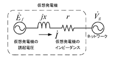
- FIG. 2 is an equivalent circuit of a modeled virtual generator included in the control unit of the power conversion apparatus of FIG.
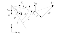
- FIG. 3 is a phasor diagram showing the relationship among the induced voltage, the phase voltage, and the line current in the equivalent circuit of the virtual generator of FIG.
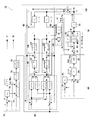
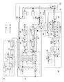
- FIG. 4 is an equivalent block diagram at the time of control of the control unit of the power conversion device of FIG. 1.
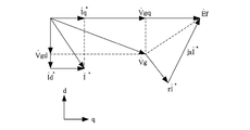
- FIG. 5 is a phasor diagram showing the relationship among the induced voltage, phase voltage, and line current in the equivalent block diagram of FIG. FIG.
- FIG. 6 is an equivalent block diagram during control of the control unit of the power conversion device according to Embodiment 2 of the present invention.
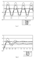
- FIG. 7 is a graph showing a simulation result by the power conversion device of FIG. 6.
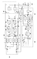
- FIG. 8 is an equivalent block diagram during control of the control unit of the power conversion device according to Embodiment 3 of the present invention.
- FIG. 9 is a graph showing a simulation result by the power conversion device of FIG. 8.
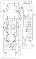
- FIG. 10 is an equivalent block diagram during control of the control unit of the power conversion device according to Embodiment 4 of the present invention.
- FIG. 11 is a graph showing a simulation result by the power conversion device of FIG. 10.
- FIG. 1 is a block diagram showing a configuration example of a microgrid using the power conversion device according to Embodiment 1 of the present invention.
- a load 11 and a DC power source 1 are connected to a distribution line (AC circuit) 9 of a microgrid (small-scale distribution network).
- the DC power source 1 is connected to the distribution line 9 via the power converter PC and the output line 2.
- Examples of the DC power source 1 include a DC power generator and a secondary battery.
- Examples of the DC power generator include a solar battery, a fuel battery, and an AC generator (for example, a gas turbine generator, an engine generator) provided with a rectifier.
- the DC power supply 1 and the power conversion device PC constitute an AC power supply device.
- the microgrid is provided with a microgrid control device (not shown) that manages the microgrid based on the setting of the operator operating the microgrid in the area of the microgrid.
- a microgrid control device (not shown) that manages the microgrid based on the setting of the operator operating the microgrid in the area of the microgrid.
- Each of the AC power supply device and the load 11 connected to the distribution line 9 of the microgrid is provided with a monitoring unit (measuring device such as electric power: not shown) for monitoring each state.
- the monitoring unit and the microgrid control device can communicate with each other via, for example, a signal line (not shown).
- the microgrid control device receives the monitoring status (measured value) from each monitoring unit, and transmits a command value such as an output power target value to the AC power supply device in accordance with the monitoring status.
- These command values are set (programmed) by the operator so as to be determined according to the monitoring status of each monitoring unit.
- the microgrid is operated independently of the commercial power system (large-scale power system) without being connected to the commercial power system (hereinafter referred to as “independent form”) and connected to the commercial power system.
- independent form There is a form (hereinafter referred to as “interconnected form”).
- interconnected form the microgrid distribution line 9 is connected to the commercial power system via, for example, a circuit breaker (not shown).
- the power conversion device PC performs the interconnection operation.
- the circuit breaker When the grid is connected to the grid, if an abnormality occurs in the commercial power system, the circuit breaker is opened and the state is the same as in the independent mode.
- the switching of the circuit breaker is controlled by, for example, a commercial power system control system (not shown).
- the power conversion device PC detects the single operation state from changes in the frequency and voltage of the output line, opens a switch (not shown), and shifts to the independent operation.
- the microgrid is operated by the interconnection
- the AC power supply device is connected to a microgrid distribution line 9 via a transformer 8.
- the power converter PC of the present embodiment constitutes an AC power supply device together with the DC power supply 1.
- the power conversion device PC converts the input DC power into AC power and outputs it to the output line 2 connected to the power system, and the three-phase output from the power conversion unit 3
- Current sensor (current measurement PC) 4 that detects output currents ia, ib, ic of each phase (a phase, b phase, c phase), output reactor 5, and each phase (a phase, b phase, c phase) )
- a voltage sensor (not shown) for detecting the voltage of the DC power supply 1 may be provided. Further, the number of phases of the wiring 9 and the output line 2 is not limited.
- the voltage sensor (voltage measurement PT) 6 detects the voltage on the secondary side of the transformer 8 here, but may detect the voltage on the primary side.
- the power conversion unit 3 includes, for example, six switching elements 3a to 3f each including a diode connected in antiparallel.
- the power converter 3 is formed of a semiconductor element, and IGBTs are used for the switching elements 3a to 3f, for example.
- the control unit 12 outputs a control signal (PWM signal) input to the control terminals (for example, the gate terminals of the IGBTs) of the switching elements 3a to 3f to the power conversion unit 3, and turns on / off the switching elements 3a to 3f.
- PWM signal control signal
- the control unit 12 is configured to control the power conversion unit 3 so that the power conversion unit 3 operates as a virtual generator.
- the control unit 12 is configured such that the virtual generator includes a generator, an AVR (automatic voltage regulator) that controls the induced voltage of the generator, a drive source that drives the generator, and a governor.
- a generator model unit 30, an AVR model unit 70, and a drive source and governor model unit 80 that define the input / output relationships of the assumed generator, AVR, drive source, and governor.
- the generator model unit 30 is a calculation unit that calculates an output with respect to the input of the generator
- the AVR model unit 70 is a calculation unit that calculates an output with respect to the input of the AVR
- the drive source and governor model unit 80 is The calculation unit calculates the output with respect to the input of the drive source and the governor.
- the concept of “the output voltage of the power converter 3” and “the output current of the power converter 3” includes not only the voltage and current on the primary side of the transformer 8 existing in the output line 2 but also the secondary side. Voltage and current are also included.
- This control unit is composed of arithmetic units such as FPGA (field programmable gate array), PLC (programmable logical controller), microcontroller, etc., and the generator model unit 30 and the power conversion control unit 20 are included in the arithmetic unit. It is a functional block realized by executing a program built in the program.
- arithmetic units such as FPGA (field programmable gate array), PLC (programmable logical controller), microcontroller, etc.
- an adder a subtracter, and an adder / subtractor are referred to as an adder / subtracter without distinction.
- the control unit 12 includes a generator model unit 30, an AVR model unit 70, a drive source and governor model unit 80, a power generation torque calculation unit 40, a rotation angle calculation unit 50, a current dq conversion unit 10, and a voltage dq conversion.
- the unit 60 although not shown, it has a power detection unit and the like.
- the power detection unit receives the output currents ia, ib, ic detected by the current sensor 4 and the output voltages va, vb, vc detected by the voltage sensor 6, and outputs the active power P and the reactive power Q from them.
- the calculated active power P is output to the drive source and governor model unit 80, and the reactive power Q is output to the AVR model unit 70.
- the power detection unit may detect the active power using, for example, a wattmeter provided on the output line 2.
- the governor and drive source model unit 80 includes an active power P output from the power conversion unit 3 to the output line 2, an active power command value P * , an angular velocity command value ⁇ *, and an angular velocity ⁇ R of the virtual generator rotor. based on, in accordance with the deviation and the deviation from the angular velocity command value of the angular velocity omega R omega * from the effective power command value of the effective power P P *, the drive torque T m of a virtual drive source for driving the virtual generator Calculate (calculate). Specifically, in the drive source and governor model unit 80, the active power command value P * and the angular velocity command value ⁇ * are input from the outside (here, the microgrid control device).
- active power P is input from the power detection unit, and angular velocity ⁇ R is input from a rotation angle calculation unit 50 described later.
- the adder / subtractor 81 outputs a value obtained by subtracting the active power P from the active power command value P * to the droop block 82.
- the droop block 82 outputs to the adder / subtractor 83 a value obtained by multiplying the output of the adder / subtractor 81 by a predetermined calculation according to the drooping characteristic of the governor (for example, a product of a real constant gain K gd ).
- Subtractor 83 a value obtained by subtracting the angular velocity omega R from the value obtained by adding the output value of the angular velocity command value omega * and the loop block 82, and outputs to the PI control block 84.
- the PI control block 84 performs proportional-integral compensation on the output of the adder / subtractor 83 by, for example, a PI regulator.
- the PI control block 84 simulates the response delay of the governor and the drive source. Note that the PI control block 84 may perform only proportional compensation.
- Driving torque output unit 85 converts the output of the PI control block 84 to the drive torque T m of a virtual drive source (e.g., gas turbines) (e.g. by multiplying a predetermined coefficient) to the rotation angle calculator 50.
- a virtual drive source e.g., gas turbines
- the angular velocity ⁇ R and the rotation angle ⁇ R of the virtual generator rotor are calculated based on at least the acceleration torque T and the inertia of the virtual generator rotor.
- the adder / subtractors 51 and 52 subtract the value obtained by subtracting the power generation torque Te input from the power generation torque calculation unit 40 and the friction torque input from the damping block 53 from the drive torque Tm. Output to.
- the unit inertia constant block 54 calculates the angular velocity ⁇ R of the rotor of the virtual generator by performing predetermined arithmetic processing using the output of the adder / subtractor 52 and the unit inertia constant J g simulating the inertia of the rotor, and the integrator 55, and output to the adder / subtractor 83 and the damping block 53.
- the damping block 53 performs a predetermined calculation using the angular velocity ⁇ R of the rotor and the damper coefficient D g that simulates the dynamic friction of the rotor, calculates the friction torque, and outputs this to the adder / subtractor 52. Note that when the calculation of the angular velocity ⁇ R of the rotor is simplified, the damping block 53 may be omitted.
- the integrator 55 integrates the input angular velocity ⁇ R of the rotor to calculate the rotation angle ⁇ R of the rotor of the virtual generator, and the voltage dq conversion unit 60, current dq conversion unit 10 and dq. Output to the inverse transform unit 25.
- AVR model unit 70 based on the reactive power Q and the output voltage V g by the power converting unit 3 and outputs to the output line 2, and the reactive power command value Q * and the voltage command value V *, the reactive power of the reactive power Q is configured to calculate the command values Q * deviation from the output voltage V g the induced voltage E f of the virtual generator in accordance with the deviation from the voltage command value V * of.
- the AVR model unit 70 receives a reactive power command value Q * and a voltage command value V * from the outside (here, a microgrid control device). Further, the reactive power Q is input from the power detection unit, the effective voltage V g is input and from the effective voltage calculation unit (not shown).
- the effective voltage calculator calculates the execution voltage V g from V gq and V gd calculated by the voltage dq converter 60 using the following equation.
- the power detection unit calculates the reactive power Q from V gq , V gd and i q , i d using the following equation.
- the adder / subtractor 71 outputs a value (reactive power deviation) obtained by subtracting the reactive power Q from the reactive power command value Q * to the droop block 72.
- the droop block 72 outputs, to the block 74, a value obtained by performing a predetermined operation on the output of the adder / subtractor 71 in accordance with the drooping characteristic of AVR (for example, a product of a real constant gain K ad ).
- the block 74 gives a first-order delay to the output of the droop block 72 and outputs this to the adder / subtractor 73.
- the reason for providing the first-order lag is to prevent the response to the reactive power deviation from becoming sensitive.
- the voltage command value V * is input to the adder / subtractor 73.
- Subtracter 73 adds the output and the voltage command value V * of block 74, further a value obtained by subtracting the effective voltage V g from the added value (voltage deviation in consideration of the reactive power deviation), the PI control block 75 Output.
- the PI control block 75 performs proportional integration compensation on the output of the adder / subtractor 73 by, for example, a PI regulator to calculate the induced voltage E f, and outputs this to the generator model unit 30 and the power generation torque calculator 40.
- the generator model unit 30 is based on the induced voltage E f calculated by the AVR model unit 70 and the d-axis component V gd and q-axis component V gq of the output voltage calculated by the voltage dq converter 60.
- a d-axis current command value i d * and a q-axis current command value i q * corresponding to the d-axis component and the q-axis component of the armature current of the generator are calculated.
- the generator model unit 30 simulates a synchronous generator using an algebraic expression defined by a phasor diagram.
- the generator model unit 30 of the present embodiment will be specifically described.
- FIG. 2 is an equivalent circuit of a modeled virtual generator included in the control unit 12 of the power conversion apparatus of FIG.
- the virtual generator generates virtual power by the induced voltage E f of the virtual generator field, the winding reactance x of the virtual armature of the virtual generator, and the winding resistance r. This is modeled using the impedance of the machine and the voltage V g (complex voltage vector) and current I (complex current vector) output from the virtual generator.
- FIG. 3 is a phasor diagram showing the relationship among the induced voltage, phase voltage (output voltage), and line current (output current (more precisely, current command value)) in the equivalent circuit of the virtual generator of FIG.
- the induced voltage E f is a q-axis reference vector. The relationship between each complex vector from the phasor diagram shown in FIG. 3 is expressed as follows.
- FIG. 4 is an equivalent block diagram during control of the control unit 12 of the power conversion device PC.
- FIG. 4 a specific configuration example of each block in FIG. 1, there is shown an equivalent circuit 130 of the feedback path of the variations in the case where the rotation angle theta R of the rotor of the virtual generator varies the .
- the equivalent circuit 130 will be described later together with the operation of the power conversion device PC.
- the algebraic expression (5) is represented by a control block as shown in block 30 of the block diagram of FIG.
- This control block when given the induced voltage E f of the virtual generator and the output voltage vectors V gq and V gd , gives a command value (d-axis current command value i d ) of the current type inverter (power converter 3). * And q-axis current command value i q ) can be calculated. Therefore, in the present embodiment, the generator model unit 30 is configured as a control model that calculates a command value for current feedback control using the algebraic expression (5) defined in the phasor diagram of FIG.
- the algebraic expression (5) includes the induced voltage E f of the synchronous generator, the d-axis component V gd and the q-axis component V gq of the output voltage, the d-axis current command value i d * and the q-axis current command. It defines the relationship between the value i q * and the winding reactance x and winding resistance r of the virtual armature of the virtual generator.
- the generator model unit 30 receives the induced voltage E f and the d-axis current command value i d * that satisfies the algebraic expression (5) for the d-axis component V gd and the q-axis component V gq of the output voltage.
- the q-axis current command value i q * is calculated.
- Generator torque calculating section 40 calculates a power generation torque T e of the virtual generator based on the calculated in AVR model portion 70 a and the induced voltage E f q-axis current command value i q * and. Specifically, as shown in the equivalent block diagram of FIG. 4, the power generation torque calculator 40 calculates the power generation torque Te by the following equation. Note that ⁇ is a time differential value of the rotation angle ⁇ of the system voltage. In this embodiment, ⁇ is a preset value.
- T e (E f / ⁇ ) ⁇ i q * (6)
- Generation torque T e of the thus virtual generator which is calculated, as described above, it is output to the rotation angle calculation unit 50, used for the calculation of acceleration torque T of the rotor of the virtual generator in the rotation angle calculation unit 50 It is done.
- the current value used to calculate the power generation torque Te in Equation (6) may be a q axis component i q of the output current of the power converter 3.
- the voltage dq converter 60 receives the output voltages va, vb, and vc of the power converter 3 detected by the voltage sensor 6.
- Voltage d-q converting section 60 calculates the d-axis component V gd and q-axis component V gq of the output voltage using the rotational angle theta R of the rotor of the virtual generator which is calculated by the rotation angle calculation unit 50. Further, the output current ia, ib, ic of the power converter 3 detected by the current sensor 4 is input to the current dq converter 10.
- Current d-q converting section 10 calculates the d-axis component i d and the q-axis component i q of the output current using the rotation angle theta R of the rotor of the virtual generator which is calculated by the rotation angle calculation unit 50. Specifically, the voltage dq conversion unit 60 and the current dq conversion unit 10 calculate V gd , V gq and i q , i d using the following equations, respectively.
- va, vb, vc, and ia, ib, ic are the output voltage and output current of the power converter 3.
- v g0 and i 0 are not used in the calculation in this embodiment.
- the generator model unit 30 the rotation angle ⁇ of the output voltage calculated by using the R d-axis component V gd and q-axis component V gq and the induced voltage calculated by the AVR model 70 on the basis of the E f, is calculated the rotational angle theta d-axis current command value as a load current corresponding to R is output i d * and the q-axis current command value i q *.
- the power conversion control unit 20 performs power conversion so as to output a current corresponding to the d-axis current command value i d * and the q-axis current command value i q * calculated by the generator model unit 30.
- Control part 3 the power conversion control unit 20 includes adders / subtractors 21 and 22, PI control blocks 23 and 24, a dq inverse conversion unit 25, and a PWM generation unit 26.
- Subtracter 21 from the d-axis current command value i d * that is input from the generator model unit 30 subtracts the d-axis component i d of the output current inputted from the current d-q power conversion unit 10, the The d-axis error current is output to the PI control block 23.
- the PI control block 23 subjects the d-axis error current to proportional integration compensation by a PI regulator, and outputs this to the dq inverse conversion unit 25.
- the adder / subtracter 22 subtracts the q-axis component i q of the output current input from the current dq power converter 10 from the q-axis current command value i q * input from the generator model unit 30.
- the q-axis error current is output to the PI control block 24.
- the PI control block 24 performs proportional-integral compensation on the q-axis error current by the PI regulator, and outputs this to the dq inverse conversion unit 25.
- d-q inverse conversion section 25 uses the rotation angle theta R of the rotor output from the integrator 55 of the rotational angle calculation unit 50, the proportional integral compensation d-axis error current and the q-axis error current the d-q
- the current command is generated by reverse conversion and is output to the PWM generator 26.
- the PWM generator 26 converts this current command into a PMW control signal and outputs it to the power converter 3. Thereby, feedback control is performed so that the output current of the power conversion unit 3 becomes a current corresponding to the d-axis current command value i d * and the q-axis current command value i q * calculated by the generator model unit 30. .
- the characteristics equivalent to the generator are realized in the power conversion device PC.
- the generator model unit 30 models the steady state of the virtual generator using a phasor diagram, thereby realizing characteristics equivalent to the generator in the power converter PC, it is called a conventional Park equation.
- the control system of the power converter is simplified.
- Figure 5 is a phasor diagram showing the relationship between the induced voltage and the phase voltage and the line current virtual generator (output current and the current command value) in a case where the rotation angle theta R of the rotor is varied.
- ⁇ is the internal phase difference angle of the virtual generator
- ⁇ is the rotation angle of the system voltage (output voltage).
- V gd and V gq are expressed by the following equations from the phasor diagram of FIG.
- V gq V g ⁇ cos ⁇ (8)
- V gd ⁇ V g ⁇ sin ⁇ (9)
- V gd, and V gq of formula (8) and (9) it is expressed from the V gq different those equivalent.
- V gd and V gq calculated by the voltage dq converter 60 are calculated from the phase voltages va, vb, and vc using Expression (7), and are used for actual control of the power converter 3.
- V gd and V gq in the equations (8) and (9) are derived from the phasor diagram of FIG. 5 and expressed using the internal phase difference angle ⁇ in order to explain the synchronization force. It is. The internal phase difference angle ⁇ is not used for actual control of the power converter 3.
- the minute change components of V gd and V gq with respect to the minute change of ⁇ are expressed by the following equations.
- block 130 shows an equivalent circuit of the feedback path of the variations in the case where the rotation angle theta R of the rotor of the virtual generator is varied.
- the block 76 in the AVR model unit 70 is a field coil transfer function. Since this transfer function has a slow response, when considering the operation of the synchronizing force of the control unit 12 (virtual generator) in the equivalent block diagram of FIG.
- Block (5, 8) represents a transfer function of the circuit of the output reactor 5 and the transformer 8 in FIG.
- R F and L F are the resistance and reactance of the output reactor 5 and the transformer 8.
- the power conversion control unit 20 has a fast response speed, and when considering the operation of the synchronization force, the influence is small and may be ignored. Therefore, as described above, in Equation (6) of the generator torque calculating section 40, q-axis current command value i q * are used in the calculation of the generation torque T e.
- V gq is positive and V gd is negative from the phasor diagram of FIG.
- the arrows indicated by dotted lines in FIG. 4 indicate positive value flows, and the arrows indicated by alternate long and short dash lines indicate negative value flows.
- T e the rotor angular velocity calculated in the rotation angle calculation unit 50 (rpm)
- rpm the rotor angular velocity calculated in the rotation angle calculation unit 50
- FIG. 6 is an equivalent block diagram at the time of control by the control unit 12 of the power conversion device according to Embodiment 2 of the present invention.
- This embodiment is different from the first embodiment, the control unit 12, the power generation torque brake and outputting the braking vibrations of the generator torque T e calculated by the power generation torque calculating section 40 in the rotation angle calculation unit 50 The difference is that 90 is further provided.
- Embodiment 1 there are two integrators in the signal transmission path, which is a typical second-order lag system, which is a so-called simple vibration model.
- a braking effect is obtained by providing a braking winding between the rotor and the stator. Therefore, in the present embodiment, a pseudo differential element is added to the calculation result of the power generation torque by the power generation torque braking unit 90 as shown in FIG.
- the braking unit is configured by a phase advance compensator as represented by the following equation.
- FIG. 7 is a graph showing a simulation result by the power conversion device of the present embodiment.
- changes with time in generator torque dotted line
- active power solid line
- reactive power two-dot chain line
- angular velocity one-dot chain line
- the graph in the upper part (a) of FIG. 7 shows the result in the case of Embodiment 1 that does not include the power generation torque braking unit 90 as a comparative example
- the results are shown respectively.
- the power generation torque of the comparative example is greatly oscillated, and the angular velocity is not constant.
- the reactive power exceeds the active power.
- FIG. 7A the power generation torque of the comparative example is greatly oscillated, and the angular velocity is not constant.
- the reactive power exceeds the active power.
- the power generation torque of the present embodiment converges the vibration and the angular velocity is substantially constant.
- the active power exceeds the reactive power.
- the generator torque braking unit 90 virtually realizes the braking winding of the synchronous generator in the virtual generator, reduces the fluctuation of the rotor of the virtual generator, and can obtain a braking effect.
- FIG. 8 is an equivalent block diagram at the time of control of the control unit 12 of the power conversion apparatus according to Embodiment 3 of the present invention.
- the control unit 12 outputs the d-axis component V gd and the q-axis component V of the output voltage supplied to the generator model unit 30 via the voltage dq conversion unit 60.
- the difference is that voltage limiting units 100 and 110 that limit the value of gq to a predetermined value are further provided.
- Embodiment 1 when the system voltage fluctuates greatly, each variable of the virtual generator moves greatly, and deviates from the range in which the generator operates stably. For this reason, the step-out occurs like the actual generator, and the operation cannot be continued. Therefore, in the present embodiment, the following processing is performed in the voltage limiting units 100 and 110. Specifically, first, it is determined whether or not the following conditional expression (12) is satisfied.
- the present inventors performed a simulation using the power conversion device of the present embodiment.
- the upper graph (a) in FIG. 9 shows the temporal change in the phase difference
- the lower graph (b) in FIG. 9 shows the temporal change in the u-phase current.
- fluctuations in the system voltage are generated around 2.4 seconds from the start.
- the phase difference is about 3.2 seconds from the start and converges to about 0 due to the synchronization action of the virtual generator.
- the u-phase current is temporarily overcurrent in the vicinity of 3 seconds from the start, but after 3.2 seconds, due to the effect of the voltage limit control by the voltage limiter 100. It is within the rated range of -150 (A) to 150 (A).
- the output of the voltage dq converter 60 is provided with the voltage limiters 100 and 110, and the output voltage is limited after the dq conversion.
- the output voltage may be limited before conversion.
- FIG. 10 is an equivalent block diagram when controlling the control unit of the power conversion device according to the fourth embodiment of the present invention.
- the present embodiment is such that the control unit 12 controls the d-axis and q-axis current command values calculated by the generator model unit 30 to be limited within predetermined limits.
- the difference is that the unit 120 is further provided.
- a current limiter is provided for the current command value in the current limit control unit 120.
- i d is in the range of -0.5pu ⁇ 0.5pu
- i q is in the range of -1.1pu ⁇ 1.1pu.
- the present inventors performed a simulation using the power conversion device of the present embodiment.
- the upper part (a) of FIG. 11 shows the time change of the phase difference
- the lower part (b) of FIG. 11 shows a graph of the time change of the u-phase current.
- fluctuations in the system voltage are generated around 2.3 seconds from the start.
- the phase difference converges to 0 around 3.2 seconds from the start due to the synchronization action of the virtual generator.
- current is not limited, and thus an overcurrent is temporarily generated.
- the u-phase current is within the rated range of ⁇ 150 (A) to 150 (A).
- the present invention can be used for a power conversion device having an interconnected operation function that operates in conjunction with an electric power system.
Abstract
系統周波数検知のためのPLL回路を用いず、且つ系統電圧又は周波数の変動に対して運転を継続することが可能な電力変換装置を提供する。 電力変換装置は、入力される直流電力を交流電力に変換する電力変換部(3)と、電力変換部(3)が仮想発電機として動作するよう電力変換部3を制御する制御部(12)を備える。制御部(12)は、仮想発電機の誘起電圧を演算するAVRモデル部(70)と、仮想発電機を駆動する駆動トルクを演算するガバナ及び駆動源モデル部(80)と、仮想発電機の発電トルクを演算する発電トルク演算部(40)と、少なくとも仮想発電機ロータの加速トルクと慣性とに基づいてロータの回転角度を演算する回転角度演算部(50)と、ロータの回転角度を用いて出力電圧のd軸成分及びq軸成分を演算する電圧d-q変換部(60)と、同期発電機の誘起電圧と相電圧と線電流との関係を表すフェーザ図で規定される代数式を用いて、仮想発電機の電機子電流のd軸成分及びq軸成分に相当するd軸電流指令値及び前記q軸電流指令値を演算する発電機モデル部(30)とを含む。
Description
本発明は、分散電源などに用いられる電力系統と連系する電力変換装置に関する。
近年、ガスエンジン発電機や燃料電池等の分散型電源を利用した電力供給システムに関心が高まっている。例えば、特定エリアにおいて、上記の分散型電源と呼ばれる発電装置を用い、この発電装置から複数の負荷へ電力供給を行うシステムが提案されている(例えば特許文献1及び特許文献2参照)。
ところで、マイクログリッドとも呼ばれるこのようなシステムは、その内部の電力系統に、上記の発電装置に加え、その発電装置の発電電力の変動や負荷変動を補償するために二次電池等を備えた電力貯蔵装置が接続されて構成されることが多い。また、電力系統が交流で発電装置が直流である場合がある。このような場合、電力を交流と直流との間で変換する電力変換装置が必要である。また、このような分散型電源を利用したシステムでは、商用電力系統とは独立して運用される自立運転と、商用電力系統と連系して運用される連系運転とが想定されており、いずれの運転においても安定した電力供給を実現することが重要である。そして、電力変換装置にもこのような安定した電力供給を可能にする機能を備えることが要求される。
そこで、本件出願人は最近、系統連系する発電機相当の特性(発電機モデル)を有する電力変換装置の制御手法を開発し、連系運転時だけでなく、自立運転時でも安定した電力を供給するとともに、連系運転から自立運転への無瞬断での移行を実現する電力変換装置を提案した。特許文献3に記載された電力変換装置では、発電機モデルとして、Parkの方程式と呼ばれる発電機のダイナミックスを記述する微分方程式が制御系に組み込まれる。一方、特許文献4に記載された従来の電力変換装置では、発電機モデルをフェーザ図で表現することによりダイナミックスを簡素化し、簡素化した発電機モデルが電力変換装置の制御系に組み込まれる。
しかしながら、特許文献3に記載の電力変換装置は、発電機モデルが、実際の発電機を模擬するためのParkの方程式と呼ばれる微分方程式系を含むために、制御回路あるいは制御プログラムが複雑化するという課題がある。
また、特許文献4に記載の電力変換装置は、系統の周波数検知のためのPLL回路を制御系の入力段に備えているが、PLL回路は制御的な時間遅れを有するので、その応答時間を決める作業や時定数の調整が必要となるため、その取扱いには高度な専門的知識が必要となる。また、系統電圧が負荷変動や系統事故によって変動した際には、PLL回路はその影響を過敏に受けやすいため、発電機モデルで実際の発電機の脱調と同様な現象が発生してしまう場合があり、その場合は所期の運転継続が阻害されてしまうという課題がある。
本発明は以上のような課題を解決するためになされたものであり、発電機相当の特性を有し、系統周波数検知のためのPLL回路を用いず、且つ系統電圧又は周波数の変動に対して運転を継続することが可能な電力変換装置を提供することを目的とする。
上記の課題を解決するために、本発明のある態様に係る電力変換装置は、入力される直流電力を交流電力に変換し、電力系統に接続される出力線へ出力するよう構成された電力変換部と、前記電力変換部が仮想発電機として動作するよう当該電力変換部を制御するよう構成された制御部と、を備え、前記制御部は、前記電力変換部が前記出力線に出力する無効電力及び出力電圧と、無効電力指令値と電圧指令値とに基づいて、前記出力電圧の前記電圧指令値からの偏差に応じた前記仮想発電機の誘起電圧を演算するように構成されたAVRモデル部と、前記電力変換部が前記出力線に出力する有効電力と、有効電力指令値と、角速度指令値と、前記仮想発電機のロータの角速度とに基づいて、当該角速度の前記角速度指令値からの偏差に応じた、前記仮想発電機を駆動する仮想駆動源の駆動トルクを演算するガバナ及び駆動源モデル部と、前記AVRモデル部で演算された誘起電圧とq軸電流指令値又は前記電力変換部の出力電流のq軸成分とに基づいて前記仮想発電機の発電トルクを演算する発電トルク演算部と、前記ガバナ及び駆動源モデル部で演算された駆動トルクから前記発電トルク演算部で演算された発電トルクを減算して前記仮想発電機のロータの加速トルクを演算し、少なくとも当該加速トルクと前記仮想発電機のロータの慣性とに基づいて前記仮想発電機のロータの前記角速度及び回転角度を演算する回転角度演算部と、前記回転角度演算部で演算された前記回転角度を用いて前記電力変換部の出力電圧のd軸成分及びq軸成分を演算する電圧d-q変換部と、同期発電機の誘起電圧と相電圧と線電流との関係を表すフェーザ図で規定される代数式を用いて、前記AVRモデル部で演算された誘起電圧と前記d-q変換部で演算された前記出力電圧のd軸成分及びq軸成分とに基づいて前記仮想発電機の電機子電流のd軸成分及びq軸成分に相当するd軸電流指令値及び前記q軸電流指令値を演算する発電機モデル部と、前記発電機モデル部で演算されたd軸電流指令値及び前記q軸電流指令値に対応する電流を出力するよう前記電力変換部を制御する電力変換制御部と、を含む。ここで「電力変換器の出力電圧」及び「電力変換器の出力電流」の概念には、出力線に変圧器が存在する場合には、一次側の電圧及び電流のみならず二次側の電圧及び電流もそれぞれ含まれる。変圧器の二次側の電圧及び電流は、電力変換器から直接出力される電力の電圧値及び電流値が単に一次巻線と二次巻線との巻き数比に応じて変換されたものに過ぎないからである。また、「演算する」ことには、ソフトウエアによって「計算する」こととハードウエア(例えば電子回路)によってアナログ演算することとを含む。
この構成によれば、仮想発電機の定常状態を、フェーザ図を用いてモデル化された発電機モデル部により発電機相当の特性が実現されるので、電力変換装置の制御系が簡素化される。また、ガバナ及び駆動源モデル部が周波数(仮想発電機のロータの角速度)の偏差に応じた仮想駆動源の駆動トルクを演算し、発電トルク演算部が負荷電流(q軸電流指令値又は出力電流のq軸成分)に応じた仮想発電機の発電トルクを演算し、回転角度演算部が駆動トルクからこの発電トルクを減算して仮想発電機のロータの加速トルクを演算する。そして、発電機モデルがこの回転角度を用いて算出された出力電圧のd軸成分及びq軸成分とAVRモデル部で演算された誘起電圧とに基づいて、当該回転角度に応じた負荷電流が出力されるようなq軸電流指令値を演算する。従って、例えば、何等かの外乱で仮想発電機のロータの回転角度が増大すると、それに応じてq軸電流指令値が増大し、それにより、仮想発電機の発電トルクが増大して加速トルクが減少する。その結果、仮想発電機のロータの回転角度が減少する。従って、仮想発電機は外乱があっても一定のロータの回転角度を維持しようとする。すなわち、制御部では、同期発電機と同様の同期化力が作用する。従って、電力系統の位相が変動した場合でも、同期化力により仮想発電機のロータの回転角度を電力系統の電圧の位相に追従させることができる。従って、PLL回路が無くても、運転を継続することができる。
前記制御部は、前記発電トルク演算部で演算された発電トルクの振動を制動して前記回転角演算部に出力する発電トルク制動部を更に備えてもよい。
この構成により、仮想発電機において、同期発電機の制動巻線が仮想的に実現されるので、仮想発電機のロータの動揺が低減され、制動効果を得ることができる。制動部は、例えば、フィルタ、位相進み補償器で構成されてもよい。
前記制御部は、前記電圧d-q変換部を介して前記発電機モデル部に与えられる前記出力電圧のd軸成分及びq軸成分の値を所定の値に制限する電圧制限部を更に備えてもよい。
この構成により、系統電圧(出力電圧)が大きく変動した場合でも、仮想発電機の各変数値が大きく変動して発電機として安定動作する範囲を逸脱するのが防止されるので、脱調を回避し、運転を継続することができる。出力電圧の制限は、d-q変換の前でも後でもよい。
前記制御部は、前記発電機モデルが演算した前記d軸及びq軸電流指令値を所定の限度内に制限するように制御する電流制限制御部を更に備えてもよい。
この構成により、定常状態における電流に比べて、変動時の電流が大きくなる現象が発生した場合でも、電力変換装置の容量を超えることがないので、運転を停止することなく継続することができる。
本発明によれば、発電機相当の特性を有し、系統周波数検知のためのPLL回路を用いず、且つ系統電圧や周波数の変動に対して運転を継続することが可能な電力変換装置を提供できる。
本発明の上記目的、他の目的、特徴、及び利点は、添付図面参照の下、以下の好適な実施態様の詳細な説明から明らかにされる。
本発明の実施の形態を、図面を参照しつつ説明する。以下では、全ての図面を通じて同一又は相当する要素には同じ符号を付して、重複する説明は省略する。
(実施の形態1)
[構成]
図1は、本発明の実施の形態1に係る電力変換装置を用いたマイクログリッドの構成例を示すブロック図である。
[構成]
図1は、本発明の実施の形態1に係る電力変換装置を用いたマイクログリッドの構成例を示すブロック図である。
図1に示すように、マイクログリッド(小規模配電網)の配電線(交流電路)9に、負荷11及び直流電源1が接続されている。直流電源1は電力変換装置PC及び出力線2を介して配電線9に接続されている。直流電源1として、直流発電装置、二次電池等が例示される。直流発電装置として、太陽電池、燃料電池、整流器を備えた交流発電機(例えばガスタービン発電機、エンジン発電機)等が例示される。直流電源1と電力変換装置PCとで交流電源装置が構成される。また、マイクログリッドには、マイクログリッドを運用する事業者の設定に基づいて、マイクログリッドを統括管理するマイクログリッド制御装置(図示せず)がマイクログリッドのエリア内に設けられている。マイクログリッドの配電線9と接続されている交流電源装置及び負荷11には、それぞれ、各々の状況を監視する監視ユニット(電力等の計測装置:図示せず)が設けられており、これらの各監視ユニットとマイクログリッド制御装置とは、例えば信号線(図示せず)を介して通信可能である。マイクログリッド制御装置は、各監視ユニットからの監視状況(計測値)を受信し、それらの監視状況に応じて、交流電源装置に対して出力電力目標値等の指令値を送信する。これらの指令値は、各監視ユニットの監視状況に応じて決まるように、事業者によって設定されている(プログラムされている)。
また、マイクログリッドは、商用電力系統(大規模電力系統)と連系することなく独立して運用される形態(以下、「独立形態」という)と、商用電力系統と連系して運用される形態(以下、「連系形態」という)とがある。連系形態の場合には、マイクログリッドの配電線9が、例えば遮断器(図示せず)を介して商用電力系統と接続される。このとき交流電源装置では、電力変換装置PCは連系運転を行っている。
マイクログリッドが連系形態の場合において、商用電力系統に異常等が発生した場合には、遮断器が開かれて、独立形態と同様の状態になる。遮断器の開閉は、例えば商用電力系統の制御システム(図示せず)によって制御される。このとき交流電源装置では、電力変換装置PCは出力線の周波数や電圧の変化から単独運転状態を検出し、図示しない開閉器を開いて自立運転へ移行する。以下では、独立形態であることに言及しない限り、マイクログリッドは連系形態で運用されており、電力変換装置PCは連系運転を行っているものとする。
交流電源装置は、変圧器8を介してマイクログリッドの配電線9と接続されている。本実施の形態の電力変換装置PCは、直流電源1とともに、交流電源装置を構成している。ここで、電力変換装置PCは、入力される直流電力を交流電力に変換し、電力系統に接続される出力線2へ出力する電力変換部3と、電力変換部3から出力される三相の各相(a相、b相、c相)の出力電流ia,ib,icを検出する電流センサ(電流測定用PC)4と、出力リアクトル5と、各相(a相、b相、c相)の出力電圧va,vb,vcを検出する電圧センサ(電圧測定用PT)6と、フィルタキャパシタ7と、電力変換部3を制御する制御部12とを備えている。なお、マイクログリッドを制御するために、直流電源1の電圧を検出する電圧センサ(図示せず)を設けてもよい。また、配線9及び出力線2の相数は限定されない。電圧センサ(電圧測定用PT)6は、ここでは変圧器8の二次側の電圧を検出しているが、一次側の電圧を検出してもよい。
電力変換部3は、例えば、それぞれ逆並列接続されたダイオードを備えた6個のスイッチング素子3a~3fにより構成されている。この電力変換部3は、半導体素子で形成され、各スイッチング素子3a~3fには例えばIGBTが用いられる。制御部12は、それぞれのスイッチング素子3a~3fの制御端子(例えばIGBTのゲート端子)に入力される制御信号(PWM信号)を電力変換部3へ出力し、各スイッチング素子3a~3fをオンオフ動作させることにより、電力変換部3をインバータとして機能させる。
制御部12は、電力変換部3が仮想発電機として動作するよう電力変換部3を制御するように構成されている。言い換えれば、制御部12は、仮想発電機が、発電機と、発電機の誘起電圧を制御するAVR(自動電圧調整器)と、発電機を駆動する駆動源及びガバナとを備えて構成されていると仮定し、仮定した発電機、AVR、駆動源及びガバナのそれぞれの入出力関係を規定する発電機モデル部30、AVRモデル部70、駆動源及びガバナモデル部80を有する。すなわち、発電機モデル部30は、発電機の入力に対する出力を演算する演算部であり、AVRモデル部70は、AVRの入力に対する出力を演算する演算部であり、駆動源及びガバナモデル部80は、駆動源及びガバナの入力に対する出力を演算する演算部である。更に、本実施の形態では、制御部12は、仮想発電機の発電トルクTeを算出する発電トルク演算部40と、仮想発電機のロータの回転角度θR等を算出する回転角度算出部50と、電力変換部3の出力電圧のd軸成分Vgd及びq軸成分Vgqを算出する電圧d-q変換部60と、電力変換部3の出力電流のd軸成分及びq軸成分を算出する電流d-q変換部10と、仮想発電機で算出された電流指令値に対応する電流を出力するよう電力変換部3を制御する電力変換制御部20とを備える。ここで、「電力変換器3の出力電圧」及び「電力変換器3の出力電流」の概念には、出力線2に存在する変圧器8の一次側の電圧及び電流のみならず二次側の電圧及び電流もそれぞれ含まれる。
この制御部は、例えば、FPGA(field programmable gate array)、PLC(programmable logic controller)、マイクロコントローラ等の演算装置で構成され、発電機モデル部30及び電力変換制御部20等は、上記演算装置においてそれに内蔵されているプログラムが実行されることにより実現される機能ブロックである。
次に、制御部12の構成について詳述する。なお、以下では、加算器、減算器及び加減算器を区別せずに、加減算器と記載する。
制御部12には、発電機モデル部30、AVRモデル部70、駆動源及びガバナモデル部80、発電トルク演算部40、回転角度算出部50、電流d-q変換部10及び電圧d-q変換部60の他、図示されていないが、電力検知部等を有する。電力検知部は、例えば、電流センサ4で検出される出力電流ia,ib,icと電圧センサ6で検出される出力電圧va,vb,vcとを受け取り、それらから有効電力P及び無効電力Qを算出し、算出した有効電力Pを駆動源及びガバナモデル部80へ出力し、無効電力QをAVRモデル部70へ出力する。なお、電力検知部は、例えば、出力線2に設けられた電力計により有効電力を検出してもよい。
ガバナ及び駆動源モデル部80は、電力変換部3が出力線2に出力する有効電力Pと、有効電力指令値P*と、角速度指令値ω*と、仮想発電機のロータの角速度ωRとに基づいて、有効電力Pの有効電力指令値P*からの偏差及び当該角速度ωRの角速度指令値ω*からの偏差に応じた、仮想発電機を駆動する仮想駆動源の駆動トルクTmを算出(演算)する。具体的には、駆動源及びガバナモデル部80では、外部(ここではマイクログリッド制御装置)から有効電力指令値P*と、角速度指令値ω*とが入力される。また、電力検知部から有効電力Pが入力され、且つ後述する回転角度算出部50から角速度ωRが入力される。加減算器81は、有効電力指令値P*から有効電力Pを減算した値をドループブロック82へ出力する。ドループブロック82は、加減算器81の出力に対しガバナの垂下特性に応じて所定の演算が施された値(例えば実定数のゲインKgdを掛けたもの)を加減算器83へ出力する。加減算器83は、角速度指令値ω*及びドループブロック82の出力値を加算した値から角速度ωRを減算した値を、PI制御ブロック84へ出力する。PI制御ブロック84は、例えば、PIレギュレータによって、加減算器83の出力に比例積分補償を施す。PI制御ブロック84は、ガバナ及び駆動源の応答遅れを模擬したものである。なお、PI制御ブロック84は比例補償のみを行ってもよい。駆動トルク出力部85は、PI制御ブロック84の出力を仮想駆動源(例えばガスタービン)の駆動トルクTmに変換して(例えば所定の係数を乗算して)回転角度算出部50へ出力する。
回転角度算出部50は、ガバナ及び駆動源モデル部80で算出された駆動トルクTmから発電トルク演算部40で算出された発電トルクTeを減算して仮想発電機のロータの加速トルクTを算出し、少なくとも当該加速トルクTと仮想発電機のロータの慣性とに基づいて仮想発電機のロータの角速度ωR及び回転角度θRを算出する。
具体的には、加減算器51及び52では、駆動トルクTmから、発電トルク演算部40から入力される発電トルクTeとダンピングブロック53から入力される摩擦トルクとを減算した値を単位慣性定数ブロック54へ出力する。単位慣性定数ブロック54は、加減算器52の出力とロータの慣性を模擬する単位慣性定数Jgを用いて所定の演算処理を行うことにより仮想発電機のロータの角速度ωRを算出し、積分器55、加減算器83及びダンピングブロック53へ出力する。ダンピングブロック53は、ロータの角速度ωRとロータの動摩擦を模擬するダンパ係数Dgを用いて所定の演算を行って摩擦トルクを算出し、これを加減算器52へ出力する。なお、ロータの角速度ωRの演算を簡略化する場合は、ダンピングブロック53を省略してもよい。積分器55は、入力されるロータの角速度ωRを積分して仮想発電機のロータの回転角度θRを算出し、電圧d-q変換部60、電流d-q変換部10及びd-q逆変換部25へ出力する。
AVRモデル部70は、電力変換部3が出力線2に出力する無効電力Q及び出力電圧Vgと、無効電力指令値Q*と電圧指令値V*とに基づいて、無効電力Qの無効電力指令値Q*からの偏差と出力電圧Vgの電圧指令値V*からの偏差とに応じた仮想発電機の誘起電圧Efを算出するように構成されている。
具体的には、AVRモデル部70は、外部(ここではマイクログリッド制御装置)から無効電力指令値Q*と電圧指令値V*とが入力される。また、電力検知部から無効電力Qが入力され、且つ実効電圧演算部(図示せず)から実効電圧Vgが入力される。ここで実効電圧演算部は、実行電圧Vgを、電圧d-q変換部60において算出されるVgq,Vgdから次式を用いて算出する。


加減算器71は、無効電力指令値Q*から無効電力Qを減算した値(無効電力偏差)をドループブロック72へ出力する。ドループブロック72は、加減算器71の出力に対しAVRの垂下特性に応じて所定の演算が施された値(例えば実定数のゲインKadを掛けたもの)をブロック74へ出力する。ブロック74は、ドループブロック72の出力に一次遅れを付与して、これを加減算器73へ出力する。一次遅れを付与する理由は、無効電力偏差に対する応答が敏感になることを防止するためである。一方、電圧指令値V*が加減算器73に入力される。加減算器73は、ブロック74の出力と電圧指令値V*とを加算し、更にその加算値から実効電圧Vgを減算した値(無効電力偏差を加味した電圧偏差)を、PI制御ブロック75へ出力する。PI制御ブロック75は、加減算器73の出力に、例えば、PIレギュレータにより比例積分補償を行って誘起電圧Efを算出し、これを発電機モデル部30及び発電トルク演算部40へ出力する。
発電機モデル部30は、AVRモデル部70で算出された誘起電圧Efと電圧d-q変換部60で算出された出力電圧のd軸成分Vgd及びq軸成分Vgqとに基づいて仮想発電機の電機子電流のd軸成分及びq軸成分に相当するd軸電流指令値id
*及びq軸電流指令値iq
*を算出する。発電機モデル部30は、フェーザ図で規定される代数式を用いて同期発電機を模擬している。以下、本実施形態の発電機モデル部30について具体的に説明する。
図2は、図1の電力変換装置の制御部12が含むモデル化された仮想発電機の等価回路である。図2の等価回路に示すように、仮想発電機は、仮想発電機の界磁による誘起電圧Efと、仮想発電機の仮想的な電機子の巻線リアクタンスx及び巻線抵抗rによる仮想発電機のインピーダンスと、仮想発電機が出力する電圧Vg(複素電圧ベクトル)及び電流I(複素電流ベクトル)と、を用いてモデル化される。
図3は、図2の仮想発電機の等価回路における誘起電圧と相電圧(出力電圧)と線電流(出力電流(正確には電流指令値))との関係を表すフェーザ図である。このフェーザ図では、誘起電圧Efがq軸の基準ベクトルである。図3に示すフェーザ図から各複素ベクトル間の関係は、以下のように表される。


代数式(5)は、図4のブロック図のブロック30に示すような制御ブロックによって表される。この制御ブロックは、仮想発電機の誘起電圧Efと出力電圧ベクトルVgq、Vgdが与えられると電流型インバータ(電力変換器3)の電流フィードバック制御の指令値(d軸電流指令値id
*及びq軸電流指令値iq)を算出することができることを意味している。そこで、本実施の形態では、発電機モデル部30は、図3のフェーザ図で規定される代数式(5)を用いて電流フィードバック制御の指令値を演算する制御モデルとして構成されている。具体的には、代数式(5)は、同期発電機の誘起電圧Efと、出力電圧のd軸成分Vgd及びq軸成分Vgqと、d軸電流指令値id
*及びq軸電流指令値iq
*と、仮想発電機の仮想的な電機子の巻線リアクタンスx及び巻線抵抗rとの関係を規定している。発電機モデル部30は、入力される、誘起電圧Efと、出力電圧のd軸成分Vgd及びq軸成分Vgqとに対し、代数式(5)を満たすd軸電流指令値id
*及びq軸電流指令値iq
*を算出する。
発電トルク演算部40は、AVRモデル部70で算出された誘起電圧Efとq軸電流指令値iq
*とに基づいて仮想発電機の発電トルクTeを算出する。具体的には、図4の等価ブロック図に示すように、発電トルク演算部40は、発電トルクTeを次式により演算する。尚、ωは系統電圧の回転角度θの時間微分値である。本実施の形態ではωは予め設定された値とする。
Te=(Ef/ω)×iq
* ・・・(6)
このようにして算出された仮想発電機の発電トルクTeは、上述のように、回転角度演算部50に出力され、回転角度演算部50において仮想発電機のロータの加速トルクTの算出に用いられる。なお、式(6)において発電トルクTeを算出するために用いる電流値は、電力変換器3の出力電流のq軸成分iqであってもよい。
このようにして算出された仮想発電機の発電トルクTeは、上述のように、回転角度演算部50に出力され、回転角度演算部50において仮想発電機のロータの加速トルクTの算出に用いられる。なお、式(6)において発電トルクTeを算出するために用いる電流値は、電力変換器3の出力電流のq軸成分iqであってもよい。
電圧d-q変換部60には、電圧センサ6で検出された電力変換部3の出力電圧va,vb,vcが入力される。電圧d-q変換部60は、回転角度演算部50で算出された仮想発電機のロータの回転角度θRを用いて当該出力電圧のd軸成分Vgd及びq軸成分Vgqを算出する。また、電流d-q変換部10には、電流センサ4で検出された電力変換部3の出力電流ia,ib,icが入力される。電流d-q変換部10は、回転角度演算部50で算出された仮想発電機のロータの回転角度θRを用いて当該出力電流のd軸成分id及びq軸成分iqを算出する。具体的には、電圧d-q変換部60及び電流d-q変換部10は、それぞれ、Vgd、Vgq及びiq,idを、次式を用いて算出する。

このように、式(7)の演算が実行され、出力電圧のd軸成分Vgd、q軸成分Vgq及び出力電流のd軸成分id及びq軸成分iqが算出される。
そして、上述のように、発電機モデル部30は、この回転角度θRを用いて算出された出力電圧のd軸成分Vgd及びq軸成分VgqとAVRモデル部70で算出された誘起電圧Efとに基づいて、当該回転角度θRに応じた負荷電流が出力されるようなd軸電流指令値id
*及びq軸電流指令値iq
*を算出する。
図1に示すように、電力変換制御部20は、発電機モデル部30で演算されたd軸電流指令値id
*及びq軸電流指令値iq
*に対応する電流を出力するよう電力変換部3を制御する。具体的には、電力変換制御部20は、加減算器21、22と、PI制御ブロック23、24と、d-q逆変換部25と、PWM生成部26とを含む。加減算器21は、発電機モデル部30から入力されるd軸電流指令値id
*から、電流d-q電力変換部10から入力される出力電流のd軸成分idを減算して、このd軸誤差電流をPI制御ブロック23に出力する。PI制御ブロック23は、このd軸誤差電流にPIレギュレータにより比例積分補償を施して、これをd-q逆変換部25に出力する。一方、加減算器22は、発電機モデル部30から入力されるq軸電流指令値iq
*から、電流d-q電力変換部10から入力される出力電流のq軸成分iqを減算して、このq軸誤差電流をPI制御ブロック24に出力する。PI制御ブロック24は、このq軸誤差電流にPIレギュレータにより比例積分補償を施して、これをd-q逆変換部25に出力する。d-q逆変換部25は、回転角度算出部50の積分器55から出力されるロータの回転角度θRを用いて、比例積分補償されたd軸誤差電流及びq軸誤差電流をd-q逆変換して電流指令を生成し、これをPWM生成部26に出力する。PWM生成部26は、この電流指令をPMW制御信号に変換して、これを電力変換部3に出力する。これにより、電力変換部3の出力電流が、発電機モデル部30で演算されたd軸電流指令値id
*及びq軸電流指令値iq
*に対応する電流になるようにフィードバック制御される。
[動作]
次に、以上のような構成の電力変換装置PCの動作を説明する。
次に、以上のような構成の電力変換装置PCの動作を説明する。
<一般的な動作>
電力変換装置PCでは、制御部12において、電力変換器3が出力する有効電力Pの有効電力指令値P*からの偏差及び仮想発電機のロータの角速度ωRの角速度指令値ω*からの偏差に応じた仮想発電機の回転角度θRが演算される。また、電力変換器3が出力する無効電力Qの無効電力指令値Q*からの偏差及び電力変換器2の出力電圧Vの電圧指令値V*からの偏差に応じた仮想発電機の誘起電圧Efが演算される。そして、これらの回転角度θR及び誘起電圧Efに応じた電流指令値id *、iq *が演算され、電力変換器3の出力電流がこれらの電流指令値id *、iq *に対応する電流になるようにフィードバック制御される。その結果、電力変換器3の出力電流が、有効電力P、無効電力Q、出力電圧、及び出力電圧の角速度が各々の指令値になる電流となるようにフィードバック制御される。
電力変換装置PCでは、制御部12において、電力変換器3が出力する有効電力Pの有効電力指令値P*からの偏差及び仮想発電機のロータの角速度ωRの角速度指令値ω*からの偏差に応じた仮想発電機の回転角度θRが演算される。また、電力変換器3が出力する無効電力Qの無効電力指令値Q*からの偏差及び電力変換器2の出力電圧Vの電圧指令値V*からの偏差に応じた仮想発電機の誘起電圧Efが演算される。そして、これらの回転角度θR及び誘起電圧Efに応じた電流指令値id *、iq *が演算され、電力変換器3の出力電流がこれらの電流指令値id *、iq *に対応する電流になるようにフィードバック制御される。その結果、電力変換器3の出力電流が、有効電力P、無効電力Q、出力電圧、及び出力電圧の角速度が各々の指令値になる電流となるようにフィードバック制御される。
かくして、電力変換装置PCにおいて発電機相当の特性が実現される。また、発電機モデル部30が仮想発電機の定常状態を、フェーザ図を用いてモデル化され、それによって電力変換装置PCにおいて発電機相当の特性が実現されるので、従来のParkの方程式と呼ばれる微分方程式を含む複雑な発電機モデルと比べて、電力変換装置の制御系が簡素化される。
<同期化力>
次に、制御部12(仮想発電機)の同期化力について、図4の等価ブロック及び図5のフェーザ図を用いて説明する。
次に、制御部12(仮想発電機)の同期化力について、図4の等価ブロック及び図5のフェーザ図を用いて説明する。
図5は、ロータの回転角度θRが変動した場合における仮想発電機の誘起電圧と相電圧と線電流(出力電流及び電流指令値)との関係を表すフェーザ図である。
図5を参照すると、δは仮想発電機の内部相差角、θは系統電圧(出力電圧)の回転角度である。例えば、系統連系中に何等かの外乱で仮想発電機のロータの回転角度θRが増大し、それに伴い内部相差角δが増加した場合を想定する。このとき図5のフェーザ図より、Vgd、Vgqは、次式で表される。
Vgq=Vg×cosδ・・・(8)
Vgd=-Vg×sinδ・・・(9)
ここで、式(8)及び式(9)のVgd、Vgqと、電圧d-q変換部60で算出されるVgd、Vgqとは表現が異なるが等価なものである。電圧d-q変換部60で算出されるVgd、Vgqは式(7)を用いて各相電圧va,vb,vcから算出され、電力変換器3の実際の制御に用いられる。これに対し、式(8)及び式(9)のVgd、Vgqは、同期化力を説明するために、図5のフェーザ図から導出され、内部相差角δを用いて表現されたものである。内部相差角δは電力変換器3の実際の制御には用いられない。式(8)及び(9)からδの微小変化分に対するVgd及びVgqの微小変化成分は次式で表される。

AVRモデル部70におけるブロック76は、界磁コイルの伝達関数である。この伝達関数は応答が遅いため、図4の等価ブロック図において制御部12(仮想発電機)の同期化力の動作について考える場合は、影響が小さいので無視してもよい。
また、ブロック(5,8)は、図1の出力リアクトル5及び変圧器8の回路の伝達関数を表している。ここでRF及びLFは、出力リアクトル5及び変圧器8の抵抗及びリアクタンスである。電力変換制御部20は応答速度が速く、同期化力の動作について考える場合は、影響が小さいので無視してもよい。従って、上述のように、発電トルク演算部40の式(6)において、発電トルクTeの演算にq軸電流指令値iq
*が用いられる。
発電機の通常の動作条件では、図5のフェーザ図より、Vgqは正、Vgdは負である。図4の点線で示した矢印は正の値の流れ、一点鎖線で示した矢印は負の値の流れをそれぞれ示している。このとき図4の点線矢印を通って、正の発電機トルクTeが戻ってきて、回転角算出部50において算出されるロータの角速度(回転数)ωRを下げようとする。これによってθRの増加率は減少し,この結果δが減少しようとする。すなわち、q軸電流指令値id*が増大し、それにより、仮想発電機の発電トルクが増大して加速トルクが減少する。その結果、仮想発電機のロータの回転角度が減少する。
次に、θRが減少して,δがそれにともない減少した場合を想定する。この場合には,上記の場合とは反対にロータの角速度(回転数)ωRを増加させようとするので、この結果、同じ理由で、δは増加するように働く。結局、δは外乱が発生してもある一定の値を取り続けようとする。従って、仮想発電機は外乱が発生しても一定のロータの回転角度を維持しようとする。すなわち、制御部12では、実際の同期発電機と同様の同期化力が作用する。
かくして、電力系統の位相が変動した場合でも、同期化力により仮想発電機のロータの回転角度を電力系統の電圧の位相に追従させることができるので、PLL回路が無くても、運転を継続することができる。
(実施の形態2)
次に、本発明の実施の形態2について、図6及び図7を用いて説明する。尚、実施の形態1と共通する構成の説明は省略し、相違する構成についてのみ説明する。
(実施の形態2)
次に、本発明の実施の形態2について、図6及び図7を用いて説明する。尚、実施の形態1と共通する構成の説明は省略し、相違する構成についてのみ説明する。
図6は、本発明の実施の形態2に係る電力変換装置の制御部12の制御時における等価ブロック図である。本実施の形態は、実施の形態1と比較すると、制御部12が、発電トルク演算部40で算出された発電トルクTeの振動を制動して回転角演算部50に出力する発電トルク制動部90を更に備える点が相違する。
実施の形態1では、信号伝達経路に積分器が二つあり、典型的な二次遅れ系となっており、いわゆる単振動モデルである。一方、現実の同期発電機ではロータとステータとの間に制動巻線を備えることにより制動効果を得ている。そこで、本実施の形態では、図5に示すような、発電トルク制動部90により、発電トルクの計算結果に対して疑似微分要素を付加する。本実施の形態では、制動部は、次式で表されるような、位相進み補償器で構成されている。

(実施の形態3)
次に、本発明の実施の形態3について、図8及び図9を用いて説明する。尚、実施の形態1と共通する構成の説明は省略し、相違する構成についてのみ説明する。
図8は、本発明の実施の形態3に係る電力変換装置の制御部12の制御時における等価ブロック図である。本実施の形態は、実施の形態1と比較すると、制御部12が、電圧d-q変換部60を介して発電機モデル部30に与えられる出力電圧のd軸成分Vgd及びq軸成分Vgqの値を所定の値に制限する電圧制限部100及び110を更に備える点が相違する。
実施の形態1では、系統電圧が大きく変動すると、仮想発電機の各変数が大きく動き、発電機として安定して動作する範囲を逸脱してしまう。このため、現実の発電機と同様に脱調が起こり、運転が継続できなくなる。そこで、本実施の形態では、電圧制限部100及び110において次のような処理を行う。具体的には、まず、次の条件式(12)が成り立つか否かを判断する。


本発明者らは、本実施の形態の電力変換装置によるシミュレーションを行った。図9の上段(a)のグラフは、位相差の時間変化を示し、図9の下段(b)のグラフは、u相電流の時間変化をそれぞれ示している。シミュレーションでは開始から2.4秒付近で系統電圧の変動を発生させている。図9(a)に示すように、位相差は開始から3.2秒付近で、仮想発電機の同期化作用により0付近まで収束している。また、図9(b)に示すようにu相電流は開始から3秒付近で一時的に過電流が発生しているが、3.2秒以降は電圧制限部100による電圧制限制御の効果により-150(A)から150(A)の定格範囲に収まっている。
このように、系統電圧(出力電圧)が大きく変動した場合でも、仮想発電機の各変数値が大きく変動し、発電機として安定動作する範囲を逸脱するのが防止されるので、脱調を回避し、運転を継続することができる。尚、本実施の形態では、電圧d-q変換部60の出力に対して電圧制限部100及び110を備える構成とし、出力電圧の制限はd-q変換後に行うようにしたが、d-q変換前に出力電圧の制限を行うような構成にしてもよい。
(実施の形態4)
次に、本発明の実施の形態4について、図10及び図11を用いて説明する。尚、実施の形態1と共通する構成の説明は省略し、相違する構成についてのみ説明する。
(実施の形態4)
次に、本発明の実施の形態4について、図10及び図11を用いて説明する。尚、実施の形態1と共通する構成の説明は省略し、相違する構成についてのみ説明する。
図10は、本発明の実施の形態4に係る電力変換装置の制御部の制御時における等価ブロック図である。本実施の形態は、実施の形態1と比較すると、制御部12が、発電機モデル部30が算出したd軸及びq軸電流指令値を所定の限度内に制限するように制御する電流制限制御部120を更に備える点が相違する。
上記実施の形態では,定常状態における電流に比べ、電圧変動時では電流が大きくなるという現象がある。この過電流が電力変換装置の容量を超えてしまって、運転が継続できない場合がある。そこで、本実施の形態では、図10のように、電流制限制御部120において電流指令値に対して,電流リミッタを設ける。
本実施の形態では電流のリミット設定値は、idは-0.5pu~0.5puの範囲とし、iqは-1.1pu~1.1puの範囲とする。
本発明者らは、本実施の形態の電力変換装置によるシミュレーションを行った。図11の上段(a)は、位相差の時間変化を示し、図11の下段(b)は、u相電流の時間変化のグラフを示している。シミュレーションでは開始から2.3秒付近で系統電圧の変動を発生させている。図11(a)に示すように、位相差は開始から3.2秒付近で仮想発電機の同期化作用により0に収束している。また、実施の形態3(図10のグラフ上段)では電流の制限を行っていないため、一時的に過電流が発生していた。しかし、本実施の形態では、図11(b)に示すように、u相電流は-150(A)から150(A)の定格範囲に収まっている。
上記構成により、定常状態における電流に比べて、変動時に過電流が発生した場合でも、電力変換装置の容量を超えることがないので、運転を停止することなく継続することができる。
上記説明から、当業者にとっては、本発明の多くの改良や他の実施形態が明らかである。従って、上記説明は、例示としてのみ解釈されるべきであり、本発明を実行する最良の態様を当業者に教示する目的で提供されたものである。本発明の精神を逸脱することなく、その構造及び/又は機能の詳細を実質的に変更できる。
本発明は、電力系統と連系して運転する連系運転機能を有する電力変換装置に用いることができる。
PC 電力変換装置
1 二次電池
2 電圧センサ
3 電力変換部
4 電流センサ
5 出力リアクトル
6 電圧センサ
7 フィルタコンデンサ
8 変圧器
9 マイクログリッドの配電線
10 電流d-q変換部
11 負荷
12 制御部
13 仮想発電機
14 マイクログリッド制御装置
15 遮断器
16 商用電力系統の配電線
20 電力変換制御部
30 発電機モデル部
40 発電トルク演算部
50 回転角度演算部
60 電圧d-q変換部
70 AVRモデル部
80 ガバナ及び駆動源モデル部
90 発電トルク制動部
100、110 電圧制限部
120 電流制限部
130 回転角度変動のフィードバック経路の等価回路
1 二次電池
2 電圧センサ
3 電力変換部
4 電流センサ
5 出力リアクトル
6 電圧センサ
7 フィルタコンデンサ
8 変圧器
9 マイクログリッドの配電線
10 電流d-q変換部
11 負荷
12 制御部
13 仮想発電機
14 マイクログリッド制御装置
15 遮断器
16 商用電力系統の配電線
20 電力変換制御部
30 発電機モデル部
40 発電トルク演算部
50 回転角度演算部
60 電圧d-q変換部
70 AVRモデル部
80 ガバナ及び駆動源モデル部
90 発電トルク制動部
100、110 電圧制限部
120 電流制限部
130 回転角度変動のフィードバック経路の等価回路
Claims (4)
- 入力される直流電力を交流電力に変換し、電力系統に接続される出力線へ出力するよう構成された電力変換部と、
前記電力変換部が仮想発電機として動作するよう当該電力変換部を制御するよう構成された制御部と、を備え、
前記制御部は、
前記電力変換部が前記出力線に出力する無効電力及び出力電圧と、無効電力指令値と電圧指令値とに基づいて、前記出力電圧の前記電圧指令値からの偏差に応じた前記仮想発電機の誘起電圧を演算するように構成されたAVRモデル部と、
前記電力変換部が前記出力線に出力する有効電力と、有効電力指令値と、角速度指令値と、前記仮想発電機のロータの角速度とに基づいて、当該角速度の前記角速度指令値からの偏差に応じた、前記仮想発電機を駆動する仮想駆動源の駆動トルクを演算するガバナ及び駆動源モデル部と、
前記AVRモデル部で演算された誘起電圧とq軸電流指令値又は前記電力変換部の出力電流のq軸成分とに基づいて前記仮想発電機の発電トルクを演算する発電トルク演算部と、
前記ガバナ及び駆動源モデル部で演算された駆動トルクから前記発電トルク演算部で演算された発電トルクを減算して前記仮想発電機のロータの加速トルクを演算し、少なくとも当該加速トルクと前記仮想発電機のロータの慣性とに基づいて前記仮想発電機のロータの前記角速度及び回転角度を演算する回転角度演算部と、
前記回転角度演算部で演算された前記回転角度を用いて前記電力変換部の出力電圧のd軸成分及びq軸成分を演算する電圧d-q変換部と、
同期発電機の誘起電圧と相電圧と線電流との関係を表すフェーザ図で規定される代数式を用いて、前記AVRモデル部で演算された誘起電圧と前記d-q変換部で演算された前記出力電圧のd軸成分及びq軸成分とに基づいて前記仮想発電機の電機子電流のd軸成分及びq軸成分に相当するd軸電流指令値及び前記q軸電流指令値を演算する発電機モデル部と、
前記発電機モデル部で演算されたd軸電流指令値及び前記q軸電流指令値に対応する電流を出力するよう前記電力変換部を制御する電力変換制御部と、を含む、電力変換装置。 - 前記制御部は、前記発電トルク演算部で演算された発電トルクの振動を制動して前記回転角演算部に出力する発電トルク制動部を更に備える、請求項1に記載の電力変換装置。
- 前記制御部は、前記電圧d-q変換部を介して前記発電機モデル部に与えられる前記出力電圧のd軸成分及びq軸成分の値を所定の値に制限する電圧制限部を更に備える、請求項1又は2に記載の電力変換装置。
- 前記制御部は、前記発電機モデルが演算した前記d軸及びq軸電流指令値を所定の限度内に制限するように制御する電流制限制御部を更に備える、請求項1乃至3のいずれかに記載の電力変換装置。
Priority Applications (2)
| Application Number | Priority Date | Filing Date | Title |
|---|---|---|---|
| US14/771,373 US9425677B2 (en) | 2013-02-28 | 2013-10-18 | Grid-interconnected power converter |
| EP13876657.1A EP2963759B1 (en) | 2013-02-28 | 2013-10-18 | Power conversion device for connection to grid |
Applications Claiming Priority (2)
| Application Number | Priority Date | Filing Date | Title |
|---|---|---|---|
| JP2013-039647 | 2013-02-28 | ||
| JP2013039647A JP6084863B2 (ja) | 2013-02-28 | 2013-02-28 | 系統連系する電力変換装置 |
Publications (1)
| Publication Number | Publication Date |
|---|---|
| WO2014132304A1 true WO2014132304A1 (ja) | 2014-09-04 |
Family
ID=51427610
Family Applications (1)
| Application Number | Title | Priority Date | Filing Date |
|---|---|---|---|
| PCT/JP2013/006190 WO2014132304A1 (ja) | 2013-02-28 | 2013-10-18 | 系統連系する電力変換装置 |
Country Status (4)
| Country | Link |
|---|---|
| US (1) | US9425677B2 (ja) |
| EP (1) | EP2963759B1 (ja) |
| JP (1) | JP6084863B2 (ja) |
| WO (1) | WO2014132304A1 (ja) |
Cited By (12)
| Publication number | Priority date | Publication date | Assignee | Title |
|---|---|---|---|---|
| CN104467001A (zh) * | 2014-12-15 | 2015-03-25 | 云南电网有限责任公司电网规划研究中心 | 一种电网电压不平衡时双馈风力发电机组直流侧电压的控制方法 |
| CN104638679A (zh) * | 2015-02-06 | 2015-05-20 | 芜湖大学科技园发展有限公司 | 一种采用自适应调节的虚拟同步发电机频率控制方法 |
| CN105305491A (zh) * | 2015-11-03 | 2016-02-03 | 国家电网公司 | 一种基于虚拟同步发电机的光伏电源控制策略 |
| CN107257138A (zh) * | 2017-07-18 | 2017-10-17 | 武汉大学 | 一种基于光伏电源的虚拟原动机输出功率调节方法 |
| CN107968591A (zh) * | 2017-12-19 | 2018-04-27 | 哈尔滨工业大学 | 基于预测公共点电压的并网逆变器虚拟惯性功率解耦控制方法 |
| CN108429290A (zh) * | 2018-04-19 | 2018-08-21 | 华北电力大学 | 基于功角稳定分析的vsg转动惯量改进自适应控制策略 |
| CN108599262A (zh) * | 2018-04-26 | 2018-09-28 | 浙江大学 | 不平衡电网下的改进虚拟同步机自同步并网运行控制方法 |
| JP2018186695A (ja) * | 2017-03-14 | 2018-11-22 | アーベーベー シュヴァイツ アクツィエンゲゼルシャフト | パワーコンバータを制御する方法および制御システム |
| CN109830986A (zh) * | 2019-03-29 | 2019-05-31 | 北方工业大学 | 一种永磁直驱风电系统的控制方法及系统 |
| CN110233505A (zh) * | 2019-06-20 | 2019-09-13 | 北方工业大学 | 基于vsg的变流器并联控制方法以及系统 |
| CN111541269A (zh) * | 2020-04-21 | 2020-08-14 | 浙江工业大学 | 虚拟同步机功率二阶解耦控制器及其功率解耦控制方法 |
| CN114128075A (zh) * | 2019-08-09 | 2022-03-01 | 三菱重工发动机和增压器株式会社 | 指令生成装置及指令生成方法 |
Families Citing this family (77)
| Publication number | Priority date | Publication date | Assignee | Title |
|---|---|---|---|---|
| EP2940826B1 (en) * | 2012-12-27 | 2018-01-31 | Kawasaki Jukogyo Kabushiki Kaisha | Combined power generation system having power converting device |
| JP6265826B2 (ja) * | 2014-04-30 | 2018-01-24 | 川崎重工業株式会社 | 単相系統に接続される電力変換装置 |
| US9948108B2 (en) * | 2014-09-30 | 2018-04-17 | Sparq Systems Inc. | DC-bus controller for an inverter |
| EP3213382A1 (en) | 2014-10-29 | 2017-09-06 | Younicos AG | System for handling short circuits on an electrical network |
| JP6437807B2 (ja) * | 2014-12-05 | 2018-12-12 | 株式会社ダイヘン | インバータ回路を制御する制御回路、および、当該制御回路を備えたインバータ装置 |
| US9543859B2 (en) * | 2015-01-23 | 2017-01-10 | Suzan EREN | System and method for active/reactive power compensation |
| JP6550897B2 (ja) * | 2015-04-27 | 2019-07-31 | 富士電機株式会社 | シミュレーション装置及びシミュレーションシステム |
| CN104953617B (zh) * | 2015-06-17 | 2017-08-11 | 清华大学 | 虚拟同步发电机带负载并网的控制方法及系统 |
| KR101546822B1 (ko) * | 2015-07-06 | 2015-08-24 | (주)누리일렉콤 | 풍력 발전기 |
| CN105071441A (zh) * | 2015-08-25 | 2015-11-18 | 南方电网科学研究院有限责任公司 | 微电网频率稳定控制方法及系统 |
| US10439507B2 (en) * | 2015-11-19 | 2019-10-08 | Ge Energy Power Conversion Technology Ltd. | Power modules with programmed virtual resistance |
| CN105811455B (zh) * | 2016-03-15 | 2020-08-28 | 中国电力科学研究院 | 一种基于虚拟同步发电特性的光储一体化控制系统 |
| CN105896614A (zh) * | 2016-04-12 | 2016-08-24 | 许继集团有限公司 | 一种光伏逆变器稳态电压平衡控制方法及系统 |
| EP3472908A1 (en) * | 2016-06-16 | 2019-04-24 | Swansea University | An energy management system and method for grid-connected and islanded micro-energy generation |
| CN105978027B (zh) * | 2016-06-21 | 2018-07-20 | 青海大学 | 一种虚拟同步发电机暂态过程的频率控制方法及系统 |
| CN106218414A (zh) * | 2016-08-26 | 2016-12-14 | 北京公共交通控股(集团)有限公司 | 无轨电车车载用电设备的供电装置及供电方法 |
| WO2018093592A1 (en) * | 2016-11-21 | 2018-05-24 | One Step Power Solutions, Inc. | Power generation system test apparatus and method |
| JP6809753B2 (ja) * | 2016-12-28 | 2021-01-06 | 川崎重工業株式会社 | 複合発電システム |
| DE102017106213A1 (de) * | 2017-03-22 | 2018-09-27 | Wobben Properties Gmbh | Verfahren zum Einspeisen elektrischer Leistung in ein elektrisches Versorgungsnetz |
| CN107069828B (zh) * | 2017-04-10 | 2019-12-10 | 华北电力大学 | 基于相差实时调整的虚拟同步发电机自同步控制方法 |
| CN106972536B (zh) * | 2017-05-08 | 2020-09-29 | 国网青海省电力公司 | 一种光伏电站虚拟同步发电机的控制方法及装置 |
| JP6834767B2 (ja) * | 2017-05-17 | 2021-02-24 | 富士電機株式会社 | 模擬装置 |
| GB2563086B (en) * | 2017-06-04 | 2020-09-16 | Zhong Qingchang | Cyber Synchronous Machine (in short, Cybersync Machine) |
| CN107102568B (zh) * | 2017-06-14 | 2020-08-04 | 华北电力科学研究院有限责任公司 | 光伏虚拟同步机并网稳定性硬件在环测试系统及方法 |
| CN107171346B (zh) * | 2017-06-14 | 2019-10-01 | 上海电力学院 | 基于虚拟同步发电机的不平衡电压控制方法 |
| CN107465189A (zh) * | 2017-08-21 | 2017-12-12 | 上海电力学院 | 基于自适应旋转惯量的虚拟同步发电机控制方法 |
| CN107591839B (zh) * | 2017-09-25 | 2020-03-31 | 江苏大学 | 基于励磁状态分析的虚拟同步发电机低电压穿越控制方法 |
| US10924035B2 (en) * | 2017-10-16 | 2021-02-16 | Mitsubishi Electric Corporation | Power conversion device |
| JP7052290B2 (ja) * | 2017-10-27 | 2022-04-12 | 東京電力ホールディングス株式会社 | 交直変換器制御装置 |
| CN107887928B (zh) * | 2017-11-27 | 2021-03-26 | 广州智光电气股份有限公司 | 一种储能系统的控制方法和装置 |
| US11451166B2 (en) * | 2017-12-11 | 2022-09-20 | Toshiba Mitsubishi-Electric Industrial Systems Corporation | Power conversion device with virtual power generation model |
| CN108134402A (zh) * | 2017-12-16 | 2018-06-08 | 西安翌飞核能装备股份有限公司 | 一种应用于光伏电站的虚拟同步发电机系统及控制方法 |
| CN108599175A (zh) * | 2017-12-16 | 2018-09-28 | 西安翌飞核能装备股份有限公司 | 一种应用于电动汽车充电桩的负荷虚拟同步发电机系统及控制方法 |
| GB2570151B (en) * | 2018-01-14 | 2020-07-15 | Zhong Qingchang | Reconfiguration of inertia, damping, and fault ride-through for a virtual synchronous machine |
| CN110137989A (zh) * | 2018-02-02 | 2019-08-16 | 中国电力科学研究院有限公司 | 一种电池储能系统的多机并联自治控制装置及方法 |
| US10305283B1 (en) * | 2018-02-22 | 2019-05-28 | General Electric Company | Power angle feedforward signal for phase locked loop in wind turbine power systems |
| EP3534522B1 (en) * | 2018-02-28 | 2021-04-28 | ABB Schweiz AG | Method and control system for controlling a voltage source converter using power-synchronisation control |
| CN108390411A (zh) * | 2018-03-21 | 2018-08-10 | 广东电网有限责任公司电力科学研究院 | 一种基于虚拟同步机储能阀值的惯量匹配方法及装置 |
| CN110311402A (zh) * | 2018-03-27 | 2019-10-08 | 中国电力科学研究院有限公司 | 一种虚拟同步发电机的控制方法及系统 |
| CN108683212B (zh) * | 2018-04-24 | 2021-10-08 | 上海电力学院 | 一种基于功率解耦的混合储能型虚拟同步发电机控制方法 |
| CN108599264B (zh) * | 2018-05-10 | 2020-11-06 | 上海交通大学 | 一种基于虚拟同步发电机控制的频率电压无差调节方法 |
| RU2697262C1 (ru) * | 2018-05-29 | 2019-08-13 | Общество с ограниченной ответственностью "Системы Постоянного Тока" | Способ управления инвертором напряжения в системах бесперебойного питания и системах накопления электрической энергии при резкопеременной нагрузке |
| CN108964094B (zh) * | 2018-06-11 | 2022-02-18 | 全球能源互联网欧洲研究院 | 基于虚拟同步发电机的区域有功频率协调控制方法及装置 |
| CN108964117A (zh) * | 2018-06-13 | 2018-12-07 | 西安理工大学 | 一种虚拟同步发电机带不平衡负载及其并联的控制方法 |
| GB2574645B (en) * | 2018-06-14 | 2020-07-15 | Zhong Qingchang | Passive virtual synchronous machine with bounded frequency and virtual flux |
| CN108879722B (zh) * | 2018-06-19 | 2021-04-27 | 全球能源互联网欧洲研究院 | 一种虚拟同步发电机的虚拟惯量生成方法 |
| CN108832657B (zh) * | 2018-06-22 | 2021-03-02 | 太原理工大学 | 交直流混合微电网双向功率变换器虚拟同步电机控制方法 |
| CN108718097B (zh) * | 2018-06-29 | 2021-11-12 | 内蒙古工业大学 | 一种适用于虚拟同步发电机低电压穿越的无缝切换系统 |
| JP7078332B2 (ja) * | 2018-09-11 | 2022-05-31 | 一般財団法人電力中央研究所 | 電圧制御型仮想同期機制御装置及び電圧制御型仮想同期機 |
| FR3086117B1 (fr) * | 2018-09-18 | 2020-12-11 | Schneider Electric Ind Sas | Procede de controle d'un generateur |
| CN109510248B (zh) * | 2018-10-19 | 2021-08-24 | 湖南大学 | 可抑制有功振荡的虚拟同步逆变器控制方法及存储介质 |
| CN109256805B (zh) * | 2018-10-19 | 2021-11-19 | 上海电力学院 | 基于单一旋转角虚拟功率的虚拟同步发电机功率解耦方法 |
| CN109617488B (zh) * | 2018-11-24 | 2021-10-15 | 浙江大学 | 一种考虑励磁电路的虚拟同步机的建模方法 |
| CN109638881B (zh) * | 2018-12-21 | 2020-12-01 | 上海交通大学 | 电网强度自适应优化的储能逆变器虚拟同步方法及系统 |
| CN113474989A (zh) * | 2018-12-28 | 2021-10-01 | 维斯塔斯风力系统集团公司 | 带有虚拟同步发电机和直流链路控制的风力涡轮机 |
| JP7292042B2 (ja) | 2019-02-01 | 2023-06-16 | 三菱重工エンジン&ターボチャージャ株式会社 | 自立運転における複合発電電源システム |
| JP7112973B2 (ja) * | 2019-02-01 | 2022-08-04 | 三菱重工エンジン&ターボチャージャ株式会社 | 指令生成装置および指令生成方法 |
| CN109787284B (zh) * | 2019-02-03 | 2020-08-18 | 浙江大学 | 一种虚拟同步机并网切入的控制方法 |
| CN109861296B (zh) * | 2019-04-10 | 2020-06-26 | 合肥工业大学 | 一种孤岛虚拟同步发电机系统的惯性和阻尼辨识方法 |
| EP3961903A4 (en) * | 2019-04-25 | 2022-04-06 | Mitsubishi Electric Corporation | CONTROL DEVICE |
| CN110277797B (zh) * | 2019-05-30 | 2020-09-01 | 合肥工业大学 | 基于共直流母线的光伏虚拟同步发电机协调控制方法 |
| JP7238608B2 (ja) * | 2019-06-03 | 2023-03-14 | 東京電力ホールディングス株式会社 | インバータ制御装置、インバータ制御プログラム及びインバータ制御方法 |
| CN110266062B (zh) * | 2019-06-20 | 2023-04-07 | 上海交通大学 | 逆变型分布式电源双层自适应惯量控制方法及装置 |
| JP6981528B2 (ja) * | 2019-08-02 | 2021-12-15 | 東芝三菱電機産業システム株式会社 | 発電システムおよびプラント制御装置 |
| CN110429659B (zh) * | 2019-08-29 | 2021-03-12 | 南方电网科学研究院有限责任公司 | 虚拟同步逆变器的动态功角调整方法、系统及相关组件 |
| CN110739722B (zh) * | 2019-10-24 | 2021-04-27 | 合肥工业大学 | 级联型逆变器有功备用式变惯性虚拟同步控制方法 |
| CN110808617A (zh) * | 2019-11-14 | 2020-02-18 | 武汉大学 | 基于磁通耦合型sfcl提高vsg低电压穿越能力的系统及方法 |
| EP3832829A1 (en) * | 2019-12-02 | 2021-06-09 | ABB Schweiz AG | Grid forming vector current control |
| AU2020433062B2 (en) * | 2020-03-05 | 2024-01-25 | Meidensha Corporation | Power conversion device control system |
| JP7374816B2 (ja) | 2020-03-05 | 2023-11-07 | 東京電力ホールディングス株式会社 | 電力変換装置の制御システム |
| CN111525828B (zh) * | 2020-05-20 | 2023-03-10 | 太原理工大学 | 基于虚拟同步电机的双向隔离型谐振功率变换器控制方法 |
| CN115769482A (zh) * | 2020-07-08 | 2023-03-07 | 特拉维夫大学拉莫特有限公司 | 具有改进的电压和频率控制的虚拟同步机 |
| CN112271723B (zh) * | 2020-09-30 | 2022-09-02 | 湖南大学 | 高过载能量变换电源动态同步转矩控制方法及系统 |
| WO2022074715A1 (ja) * | 2020-10-05 | 2022-04-14 | 東芝三菱電機産業システム株式会社 | 電力変換装置の制御装置 |
| DE102021105119B4 (de) * | 2021-03-03 | 2023-01-12 | Sma Solar Technology Ag | Verfahren zum Betreiben eines Wechselrichters und Wechselrichter |
| CN113890065A (zh) * | 2021-11-09 | 2022-01-04 | 广东志成冠军集团有限公司 | 柴储独立微电网及其虚拟动态同步控制方法、系统 |
| CN115833266B (zh) * | 2023-02-14 | 2023-04-21 | 中国科学院电工研究所 | 新能源电力系统中跟网型变流器集群聚合控制方法 |
Citations (7)
| Publication number | Priority date | Publication date | Assignee | Title |
|---|---|---|---|---|
| JP2009081942A (ja) | 2007-09-26 | 2009-04-16 | Yanmar Co Ltd | 分散電源システム |
| JP2009225599A (ja) | 2008-03-18 | 2009-10-01 | Kawasaki Heavy Ind Ltd | 電力変換装置 |
| JP2011155795A (ja) | 2010-01-28 | 2011-08-11 | Toshiba Corp | 太陽光発電運用システム |
| US20110270463A1 (en) * | 2008-11-12 | 2011-11-03 | George Weiss | Static synchronous generators |
| JP2012143018A (ja) | 2010-12-28 | 2012-07-26 | Kawasaki Heavy Ind Ltd | 系統安定化装置および系統安定化方法 |
| WO2013008413A1 (ja) * | 2011-07-08 | 2013-01-17 | 川崎重工業株式会社 | 複合発電システム向け電力変換装置 |
| JP2013162623A (ja) * | 2012-02-03 | 2013-08-19 | Toshiba Corp | 給電システム |
Family Cites Families (13)
| Publication number | Priority date | Publication date | Assignee | Title |
|---|---|---|---|---|
| JPS58123394A (ja) * | 1982-01-18 | 1983-07-22 | Hitachi Ltd | 交流電動機の制御装置 |
| JPH07118956B2 (ja) * | 1987-02-17 | 1995-12-18 | 株式会社明電舎 | ベクトル制御装置 |
| CA2011563C (en) * | 1989-03-08 | 1994-05-10 | Kiyoshi Nakata | Power conversion system |
| KR100371370B1 (ko) * | 2000-08-18 | 2003-02-06 | 엘지산전 주식회사 | 벡터 제어장치 |
| JP3726713B2 (ja) * | 2001-06-14 | 2005-12-14 | 日産自動車株式会社 | 電動機の制御装置 |
| JP3928575B2 (ja) * | 2003-04-07 | 2007-06-13 | 日産自動車株式会社 | モーター制御装置 |
| KR20050003732A (ko) * | 2003-07-04 | 2005-01-12 | 현대자동차주식회사 | 유도 전동기용 벡터 제어형 듀얼 인버터 시스템 |
| JP4556572B2 (ja) * | 2004-09-09 | 2010-10-06 | アイシン・エィ・ダブリュ株式会社 | 電動駆動制御装置、電動駆動制御方法及びプログラム |
| EP1635448B1 (en) * | 2004-09-09 | 2006-12-20 | ABB Oy | Speed sensorless control of an induction machine using a PWM inverter with output LC filter |
| CN101204003B (zh) * | 2005-06-27 | 2010-05-19 | 国立大学法人德岛大学 | 电力变换控制装置以及电力变换控制方法 |
| JP4680102B2 (ja) * | 2006-03-07 | 2011-05-11 | 川崎重工業株式会社 | 電力変換装置 |
| EP2164169B1 (en) * | 2007-04-16 | 2017-08-09 | Mitsubishi Electric Corporation | Electric motor control apparatus |
| JP5146478B2 (ja) * | 2010-03-18 | 2013-02-20 | 株式会社デンソー | 回転機の制御装置 |
-
2013
- 2013-02-28 JP JP2013039647A patent/JP6084863B2/ja active Active
- 2013-10-18 EP EP13876657.1A patent/EP2963759B1/en active Active
- 2013-10-18 US US14/771,373 patent/US9425677B2/en active Active
- 2013-10-18 WO PCT/JP2013/006190 patent/WO2014132304A1/ja active Application Filing
Patent Citations (7)
| Publication number | Priority date | Publication date | Assignee | Title |
|---|---|---|---|---|
| JP2009081942A (ja) | 2007-09-26 | 2009-04-16 | Yanmar Co Ltd | 分散電源システム |
| JP2009225599A (ja) | 2008-03-18 | 2009-10-01 | Kawasaki Heavy Ind Ltd | 電力変換装置 |
| US20110270463A1 (en) * | 2008-11-12 | 2011-11-03 | George Weiss | Static synchronous generators |
| JP2011155795A (ja) | 2010-01-28 | 2011-08-11 | Toshiba Corp | 太陽光発電運用システム |
| JP2012143018A (ja) | 2010-12-28 | 2012-07-26 | Kawasaki Heavy Ind Ltd | 系統安定化装置および系統安定化方法 |
| WO2013008413A1 (ja) * | 2011-07-08 | 2013-01-17 | 川崎重工業株式会社 | 複合発電システム向け電力変換装置 |
| JP2013162623A (ja) * | 2012-02-03 | 2013-08-19 | Toshiba Corp | 給電システム |
Non-Patent Citations (1)
| Title |
|---|
| YUKO HIRASE: "A Grid Connected Inverter with Virtual Synchronous Generator Model of Algebraic Type", THE TRANSACTIONS OF THE INSTITUTE OF ELECTRICAL ENGINEERS OF JAPAN B, vol. 132, no. 4, 1 April 2012 (2012-04-01), pages 371 - 380, XP007922480 * |
Cited By (18)
| Publication number | Priority date | Publication date | Assignee | Title |
|---|---|---|---|---|
| CN104467001A (zh) * | 2014-12-15 | 2015-03-25 | 云南电网有限责任公司电网规划研究中心 | 一种电网电压不平衡时双馈风力发电机组直流侧电压的控制方法 |
| CN104638679A (zh) * | 2015-02-06 | 2015-05-20 | 芜湖大学科技园发展有限公司 | 一种采用自适应调节的虚拟同步发电机频率控制方法 |
| CN105305491A (zh) * | 2015-11-03 | 2016-02-03 | 国家电网公司 | 一种基于虚拟同步发电机的光伏电源控制策略 |
| US11239779B2 (en) | 2017-03-14 | 2022-02-01 | Abb Schweiz Ag | Method and control system for controlling a power converter |
| JP2018186695A (ja) * | 2017-03-14 | 2018-11-22 | アーベーベー シュヴァイツ アクツィエンゲゼルシャフト | パワーコンバータを制御する方法および制御システム |
| CN107257138B (zh) * | 2017-07-18 | 2020-04-10 | 武汉大学 | 一种基于光伏电源的虚拟原动机输出功率调节方法 |
| CN107257138A (zh) * | 2017-07-18 | 2017-10-17 | 武汉大学 | 一种基于光伏电源的虚拟原动机输出功率调节方法 |
| CN107968591A (zh) * | 2017-12-19 | 2018-04-27 | 哈尔滨工业大学 | 基于预测公共点电压的并网逆变器虚拟惯性功率解耦控制方法 |
| CN107968591B (zh) * | 2017-12-19 | 2020-04-14 | 哈尔滨工业大学 | 基于预测公共点电压的并网逆变器虚拟惯性功率解耦控制方法 |
| CN108429290A (zh) * | 2018-04-19 | 2018-08-21 | 华北电力大学 | 基于功角稳定分析的vsg转动惯量改进自适应控制策略 |
| CN108599262B (zh) * | 2018-04-26 | 2020-04-28 | 浙江大学 | 不平衡电网下的改进虚拟同步机自同步并网运行控制方法 |
| CN108599262A (zh) * | 2018-04-26 | 2018-09-28 | 浙江大学 | 不平衡电网下的改进虚拟同步机自同步并网运行控制方法 |
| CN109830986A (zh) * | 2019-03-29 | 2019-05-31 | 北方工业大学 | 一种永磁直驱风电系统的控制方法及系统 |
| CN109830986B (zh) * | 2019-03-29 | 2021-03-26 | 北方工业大学 | 一种永磁直驱风电系统的控制方法及系统 |
| CN110233505A (zh) * | 2019-06-20 | 2019-09-13 | 北方工业大学 | 基于vsg的变流器并联控制方法以及系统 |
| CN114128075A (zh) * | 2019-08-09 | 2022-03-01 | 三菱重工发动机和增压器株式会社 | 指令生成装置及指令生成方法 |
| CN114128075B (zh) * | 2019-08-09 | 2024-03-22 | 三菱重工发动机和增压器株式会社 | 指令生成装置及指令生成方法 |
| CN111541269A (zh) * | 2020-04-21 | 2020-08-14 | 浙江工业大学 | 虚拟同步机功率二阶解耦控制器及其功率解耦控制方法 |
Also Published As
| Publication number | Publication date |
|---|---|
| JP6084863B2 (ja) | 2017-02-22 |
| EP2963759B1 (en) | 2018-09-19 |
| US20160006338A1 (en) | 2016-01-07 |
| US9425677B2 (en) | 2016-08-23 |
| JP2014168351A (ja) | 2014-09-11 |
| EP2963759A4 (en) | 2017-04-19 |
| EP2963759A1 (en) | 2016-01-06 |
Similar Documents
| Publication | Publication Date | Title |
|---|---|---|
| JP6084863B2 (ja) | 系統連系する電力変換装置 | |
| JP5408889B2 (ja) | 電力変換装置 | |
| JP4680102B2 (ja) | 電力変換装置 | |
| Hirase et al. | Analysis of resonance in microgrids and effects of system frequency stabilization using a virtual synchronous generator | |
| US8698461B2 (en) | Direct power control with component separation | |
| JP6265826B2 (ja) | 単相系統に接続される電力変換装置 | |
| JP6386718B2 (ja) | 電力変換装置 | |
| JP5956991B2 (ja) | 複合発電システム向け電力変換装置 | |
| WO2019187411A1 (ja) | 分散電源の制御装置 | |
| Kassem et al. | Robust control of an isolated hybrid wind–diesel power system using linear quadratic Gaussian approach | |
| US8861239B2 (en) | Regulating output characteristics of static energy supply units | |
| JP6006637B2 (ja) | 電力変換制御装置 | |
| US20210175711A1 (en) | Power supply system and control method | |
| Hirase et al. | Effects of suppressing frequency fluctuations by parallel operation of virtual synchronous generator in microgrids | |
| Khajesalehi et al. | Fault-tolerant virtual synchronous generator control of inverters in synchronous generator-based microgrids | |
| CN114204860A (zh) | 基于虚拟同步发电技术的三相逆变器控制方法及系统 | |
| Ryan et al. | Frequency response of motor drive loads in microgrids | |
| EP3968484A1 (en) | Control for electrical converters | |
| Hirase et al. | Effects and analysis of suppressing frequency fluctuations in microgrids using virtual synchronous generator control | |
| Uthayakumar et al. | Sensor fault control scheme for a variable speed wind energy system in a stand‐alone DC micro grid | |
| JP6113561B2 (ja) | 系統連系インバータ及び系統連系インバータの制御装置 | |
| Silva et al. | Rotor flux vector control of DFIG without currents rotor sensor | |
| JP5693337B2 (ja) | 発電機の制御装置 | |
| JP7139585B2 (ja) | 電力変換器の制御装置、制御方法、制御プログラム | |
| WO2023203641A1 (ja) | 分散電源統合管理装置及び電力システム |
Legal Events
| Date | Code | Title | Description |
|---|---|---|---|
| 121 | Ep: the epo has been informed by wipo that ep was designated in this application |
Ref document number: 13876657 Country of ref document: EP Kind code of ref document: A1 |
|
| NENP | Non-entry into the national phase |
Ref country code: DE |
|
| WWE | Wipo information: entry into national phase |
Ref document number: 14771373 Country of ref document: US |
|
| WWE | Wipo information: entry into national phase |
Ref document number: 2013876657 Country of ref document: EP |