WO2014128978A1 - Cabine de machine de construction et machine de construction - Google Patents
Cabine de machine de construction et machine de construction Download PDFInfo
- Publication number
- WO2014128978A1 WO2014128978A1 PCT/JP2013/056772 JP2013056772W WO2014128978A1 WO 2014128978 A1 WO2014128978 A1 WO 2014128978A1 JP 2013056772 W JP2013056772 W JP 2013056772W WO 2014128978 A1 WO2014128978 A1 WO 2014128978A1
- Authority
- WO
- WIPO (PCT)
- Prior art keywords
- hollow tube
- hole
- handle
- dimension
- cab
- Prior art date
Links
Images


Classifications
-
- E—FIXED CONSTRUCTIONS
- E05—LOCKS; KEYS; WINDOW OR DOOR FITTINGS; SAFES
- E05B—LOCKS; ACCESSORIES THEREFOR; HANDCUFFS
- E05B85/00—Details of vehicle locks not provided for in groups E05B77/00 - E05B83/00
- E05B85/10—Handles
- E05B85/14—Handles pivoted about an axis parallel to the wing
-
- E—FIXED CONSTRUCTIONS
- E02—HYDRAULIC ENGINEERING; FOUNDATIONS; SOIL SHIFTING
- E02F—DREDGING; SOIL-SHIFTING
- E02F9/00—Component parts of dredgers or soil-shifting machines, not restricted to one of the kinds covered by groups E02F3/00 - E02F7/00
- E02F9/16—Cabins, platforms, or the like, for drivers
- E02F9/163—Structures to protect drivers, e.g. cabins, doors for cabins; Falling object protection structure [FOPS]; Roll over protection structure [ROPS]
-
- E—FIXED CONSTRUCTIONS
- E05—LOCKS; KEYS; WINDOW OR DOOR FITTINGS; SAFES
- E05B—LOCKS; ACCESSORIES THEREFOR; HANDCUFFS
- E05B79/00—Mounting or connecting vehicle locks or parts thereof
- E05B79/10—Connections between movable lock parts
- E05B79/20—Connections between movable lock parts using flexible connections, e.g. Bowden cables
-
- E—FIXED CONSTRUCTIONS
- E05—LOCKS; KEYS; WINDOW OR DOOR FITTINGS; SAFES
- E05B—LOCKS; ACCESSORIES THEREFOR; HANDCUFFS
- E05B83/00—Vehicle locks specially adapted for particular types of wing or vehicle
- E05B83/36—Locks for passenger or like doors
- E05B83/42—Locks for passenger or like doors for large commercial vehicles, e.g. trucks, construction vehicles or vehicles for mass transport
Definitions
- the present invention relates to a cab for a construction machine and a construction machine, and more particularly, to a cab for a construction machine including a door and a door opening / closing mechanism for opening and closing the door, and a construction machine including the cab.
- Patent Document 1 A door handle of a work vehicle is disclosed in, for example, US Patent Application Publication No. 2010/0045052 (Patent Document 1).
- This US Patent Application Publication No. 2010/0045052 describes a door lock mechanism that allows an operator to release a door lock from the inside of a vehicle such as an agricultural machine by pressing a remote activation button provided on a transverse tube. Yes.
- the operator can push the remote operation button into the transverse tube by grasping the remote operation button together with the transverse tube, and can unlock the door with a simple operation.
- the present invention has been made in view of the above problems, and an object of the present invention is to provide a construction machine cab that can open and close a door with a simple operation and that does not allow an operator to pinch fingers or palms when the door is opened and closed. It is to provide a construction machine equipped.
- the construction machine cab of the present invention is a construction machine cab provided with a door and a door opening / closing mechanism for opening and closing the door.
- the door opening / closing mechanism includes a hollow tube and a handle.
- the hollow tube has a hollow space inside and a hole connecting the hollow space and the outside.
- the handle has a root portion located from outside through the hole into the hollow space, and a grip portion located at the outer end facing the hollow space end of the root portion, and the hollow space. It is supported by the hollow tube so as to be movable in the direction of pushing to the side.
- the hole includes a first hole portion located at one end of the root portion along the length direction of the hollow tube, and a second hole portion located from the first hole portion to the other end side in the length direction. Have.
- the dimension in the width direction orthogonal to the length direction of the grip part is larger than the dimension in the width direction of the root part and larger than the dimension in the width direction of the second hole part.
- the handle is supported by the hollow tube so as to be movable in the direction of pushing into the hollow space side.
- the operator can open and close the door by a simple operation of grasping both the hollow tube and the handle and pushing the handle into the hollow space.
- the dimension in the width direction of the grip part is larger than the dimension in the width direction of the root part, and larger than the dimension in the width direction of the second hole part.
- the dimension in the width direction of the first hole is larger than the dimension in the width direction of the second hole.
- the gap between the corner and the first hole at one end of the root portion where the operator's finger is easily pinched can be increased. It is possible to suppress the operator's finger from being pinched. Further, since the gap in the width direction between the base portion and the second hole can be reduced by reducing the width direction dimension of the second hole portion, the handle becomes loose against the hollow tube due to the increase in the gap. Can be suppressed.
- the hollow tube is a round pipe. Accordingly, the operator's finger or palm can easily escape from between the grip portion and the hollow tube along the outer peripheral surface of the hollow tube of the round pipe. For this reason, it becomes more difficult for an operator to pinch a finger or a palm in the gap between the root of the handle and the hole of the hollow tube.
- the dimension in the width direction of the grip portion is smaller than the dimension in the width direction of the hollow tube.
- the dimension of the root portion in the direction from the hollow space side to the outer side is larger than the dimension in the height direction of the hollow tube.
- the root portion is supported by the hollow tube so as to be rotatable on the other end side in the length direction, and the one end of the root portion is separated from the rotation center of the handle as the grip portion is approached. Has an inclination.
- the grip portion has an inclined portion at one end that is separated from the hollow tube toward the one end from the other end side.
- the operator can recognize the position of his / her index finger with respect to the grip portion of the handle without visually observing the inclined portion at one end. Further, the handle can be operated with a small operating force by pushing the inclined portion at one end farthest from the other end side as the rotation center into the hollow space side with the index finger.
- a construction machine according to the present invention includes the construction machine cab described above. According to the construction machine of the present invention, it is possible to open and close the door with a simple operation, and it is difficult for the operator to pinch fingers and palms when the door is opened and closed.
- FIG. 3 is an enlarged perspective view (A) and an exploded perspective view (B) showing a configuration of a cab door opening / closing mechanism shown in FIG. 2. It is a figure for demonstrating the dimension of the hole of the hollow tube in the door opening / closing mechanism of the cab shown in FIG. It is a figure which shows operation
- the partially broken side view (A) which shows the state before a handle is pushed into the hollow space side, and the state where the handle was pushed into the hollow space side
- Embodiment 1 of the present invention a configuration of a wheel loader as an example of a construction machine according to Embodiment 1 of the present invention will be described with reference to FIG. 1.
- the present invention is applied to a construction machine having a cab having a door opening / closing mechanism such as a hydraulic excavator or a bulldozer. Is possible.
- the wheel loader 30 of the present embodiment mainly includes a front frame 21, a rear vehicle body 22, and a work implement 23.
- a front wheel 24 a is attached to each of both sides of the front frame 21, and a rear wheel 24 b is attached to each of both sides of the rear vehicle body 22.
- the front frame 21 and the rear vehicle body 22 are attached to a left and right swingable by a center pin (not shown) to constitute an articulate structure. That is, the front frame 21 and the rear vehicle body 22 are connected by a pair of left and right steering cylinders (not shown). By extending and contracting the left and right steering cylinders, the front frame 21 and the rear vehicle body 22 have a center pin. It is configured to swing left and right as a center and steer.
- the front frame 21 and the rear vehicle body 22 constitute a vehicle body of the wheel loader 30.
- a work machine 23 is attached in front of the front frame 21.
- the work machine 23 has a boom 23a whose base end is swingably attached to the front frame 21, and a bucket 23b swingably attached to the distal end of the boom 23a.
- the front frame 21 and the boom 23a are connected by a pair of boom cylinders 23c, and the boom 23a swings by extending and contracting the pair of boom cylinders 23c.
- the work machine 23 includes a bell crank 23d that is swingably supported by the boom 23a at a substantially central portion thereof, a bucket cylinder 23e that connects the base end portion of the bell crank 23d and the front frame 21, and a bell crank.
- a link 23f that connects the tip of 23d and the bucket 23b.
- An engine chamber 22b is disposed behind the rear vehicle body 22, and a hydraulic oil tank 22a is disposed in front of the engine chamber 22b.
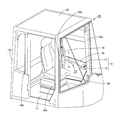
- a cab 20 is provided for an operator to enter the inside and operate the wheel loader 30.
- the cab 20 of the present embodiment includes a door opening / closing mechanism 10, a door 15, a driver's seat 16, a floor plate 17, a pair of front pillars 18a, a pair of center pillars 18b, A pair of rear pillars 18c and a roof 19 are mainly provided.
- a pair of front pillars 18a, a pair of center pillars 18b, and a pair of rear pillars 18c are erected.
- a roof 19 is supported on the upper ends of the pillars 18a, 18b, and 18c.
- a driver seat 16 for an operator to sit is disposed in the space surrounded by the floor plate 17, the pillars 18 a, 18 b, 18 c and the roof 19, a driver seat 16 for an operator to sit is disposed.
- a door 15 is disposed on the side of the driver's seat 16 (in the width direction of the vehicle body) and between the front pillar 18a and the center pillar 18b. The door 15 is used by an operator to enter and exit the cab 20 and is attached to the cab 20 so as to be openable and closable.
- a door opening / closing mechanism 10 for opening and closing the door 15 is attached to the door 15 and the front pillar 18a.
- the door opening / closing mechanism 10 mainly includes a lock assembly 13 having a catcher 11 and a striker 12, a hollow tube 1, and a handle 2.
- the one end of the hollow tube 1 is connected to a catcher 11, and the other end of the hollow tube 1 is connected to a tube 14 extending in the vertical direction of the vehicle body.
- the pipe 14 is attached to the door 15 at both ends.
- the catcher 11 has a claw portion (not shown), and this claw portion can be engaged with a bar member (not shown) of the striker 12.
- the handle 2 is attached to the hollow tube 1. By pushing the handle 2 toward the hollow tube 1, the engagement state between the claw portion of the catcher 11 and the bar member of the striker 12 can be released, and the door 15 can be opened.
- the door opening / closing mechanism 10 includes a fixture 3, a bolt 4, a rotating portion 5, and a wire in addition to the hollow tube 1 and the handle 2. 6.
- the hollow tube 1 has a pipe shape having a hollow space 1e inside, for example, a round pipe shape having a circular cross section.
- the hollow tube 1 has a hole 1a that connects the hollow space 1e and the outside.
- the handle 2 has a root portion 2a and a grip portion 2b.
- the root portion 2a and the grip portion 2b are integrally formed, and are formed by integral resin molding, for example.
- the root portion 2a is located over the hollow space 1e from the outside of the hollow tube 1 through the hole 1a.
- the root portion 2a has a hollow space side end portion 2a 1 and an outer side end portion 2a 2 which are opposed to each other in the height direction of the handle 2 (in the direction of arrow H in the figure).
- the root portion 2a has a pair of side surfaces 2ac that face each other in the width direction of the handle (in the direction of arrow W in the figure).
- the pair of side surfaces 2ac face each other between the hollow space side end 2a 1 and the outer side end 2a 2 so as to be parallel to each other.
- a hole 2ad is formed in each of the pair of side surfaces 2ac on the one end 2aa side of the root portion 2a along the length direction (arrow L direction in the drawing) of the hollow tube 1, and the pair of side surfaces on the other end 2ab side.
- a hole 2ae is formed in each 2ac.
- the width direction W is a direction orthogonal to the length direction L
- the height direction H is a direction orthogonal to both the length direction L and the width direction W.
- the grip portion 2b is located at the outer end 2a 2 of the root portion 2a, and is a portion that comes into contact with the operator's finger when the operator performs the door opening / closing operation. For this reason, on the surface opposite to the base portion 2a side of the grip portion 2b, gently wavy unevenness for attaching four fingers (index finger, middle finger, ring finger, little finger) is formed. In addition, since there is an inclined portion that is further away from the hollow tube 1 toward the front in front of the grip portion 2b, the operator can recognize the position of his / her finger relative to the grip portion 2b without looking at the handle. In the opening / closing operation of the door 15 (FIG. 2), the four fingers can be prevented from shifting from the grip portion 2b.
- the handle 2 is supported by the hollow tube 1 so as to be movable at least in the direction of being pushed into the hollow space 1e, and specifically has the following configuration.
- the fixture 3 is disposed in the hollow space 1 e of the hollow tube 1.
- the bolt 4 passes through the insertion hole 1 d of the hollow tube 1 and is screwed into the screw hole 3 b of the fixture 3.
- the fixture 3 is fixed to the hollow tube 1 in the hollow space 1 e by the bolt 4.
- This fixing tool 3 has a pair of shaft portions 3a protruding sideways from each of both side portions thereof.
- the pair of shaft portions 3a extends, for example, in a direction parallel to the tangent to the outer peripheral surface of the hollow tube 1 in a state where the fixture 3 is attached to the hollow tube 1. Yes.
- the fixture 3 is disposed between the pair of side surfaces 2ac of the root portion 2a.
- Each of the pair of shaft portions 3 a is inserted into the pair of holes 2 ae of the base portion 2 a and is disposed so as to extend along the width direction W of the handle 2.
- the handle 2 can be rotated around the pair of shaft portions 3a with respect to the hollow tube 1, and is supported by the hollow tube 1 so as to be movable in the direction of pushing into the hollow space 1e and in the opposite direction. Yes.
- the handle 2 is configured so as to be able to perform an operation such as pulling the wire 6 connected to the catcher 11 (FIG. 2) by the above movement operation (for example, a rotation operation). It has the structure as follows.
- the rotating part 5 is disposed between a pair of side surfaces 2ac of the root part 2a. Moreover, the rotation part 5 has a pair of axial part 5a which protrudes to the side from each of both side parts in the one end 5b side. Each of the pair of shaft portions 5 a is inserted into the pair of holes 2 ad of the root portion 2 a and is disposed so as to extend along the width direction W of the handle 2. Thereby, the rotation part 5 can rotate with respect to the handle
- the wire 6 is attached to the other end 5c side of the rotating portion 5, and the wire 6 extends in the hollow space 1e of the hollow tube 1 and reaches the catcher 11 (FIG. 2).
- the rotating unit 5 rotates with respect to the handle 2, an operation such as pulling the wire 6 is possible.
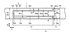
- hole 1a has a first hole 1c and a second hole 1b.
- the first hole portion 1 c is located at one end 2 aa of the root portion 2 a along the length direction L of the hollow tube 1.
- the second hole 1b is located on the other end 2ab side of the root 2a from the end of the first hole 1c.
- the dimension W2b in the width direction W of the grip part 2b of the handle 2 is larger than the dimension W2a in the width direction W of the root part 2a and larger than the dimension W1a in the width direction W of the second hole 1b.
- the dimension W1b in the width direction W of the first hole 1c is larger than the dimension W1a in the width direction W of the second hole 1b.
- the dimension G2 in the width direction W of the gap between the corner portion P1 and the first hole portion 1c at the one end 2aa of the root portion 2a is between the side surface 2ac of the root portion 2a and the second hole portion 1b. Is larger than the dimension G1 in the width direction W of the gap.
- the dimension W2b in the width direction W of the grip portion 2b is smaller than the dimension W1 (for example, the diameter D) in the width direction W of the hollow tube 1.
- the boundary B between the first hole 1c and the second hole 1b is located on the other end 2ab side by a predetermined length L1 from one end 2aa of the root portion 2a.
- the dimension W2b is preferably greater than or equal to the dimension W1b.
- the dimension G3 in the length direction L of the gap between the one end 2aa of the root portion 2a and the first hole 1c is the gap between the other end 2ab of the root portion 2a and the second hole 1b. It is larger than the dimension G4 in the length direction L.
- the insertion hole 1d is a long hole, and the length direction L of the gap between the one end 2aa of the root portion 2a and the first hole portion 1c even if the position of the handle is adjusted back and forth (L direction).
- the dimension G3 can secure a predetermined gap.
- a wide portion 1ba that widens the width of the second hole portion 1b may be formed on the other end side in the length direction L of the second hole portion 1b.
- the dimension W1c in the width direction W of the second hole 1b in the part where the wide part 1ba is formed is larger than the dimension W1a in the width direction W of the second hole 1b in the part where the wide part 1ba is not formed. Is also big.
- the handle 2 is not in contact with the inner peripheral surface of the hollow tube 1 before the handle 2 is pushed into the hollow space 1e side of the hollow tube 1. That is, the portion P2 located closest to the hollow space 1e at the one end 2aa of the root portion 2a is spaced apart from the portion P3 on the inner peripheral surface of the hollow tube 1 that intersects the rotation locus (one-dot chain line CC). Away. In this state, the other end 5 c side of the rotating portion 5 is in contact with the inner peripheral surface of the hollow tube 1.
- the handle 2 rotates until the portion P2 of the root portion 2a contacts the portion P3 of the inner peripheral surface of the hollow tube 1 by the above operation.
- the rotating portion 5 rotates with respect to the handle 2 around the shaft portion 5a.
- the other end 5 c side of the rotating unit 5 moves to the other end 2 ab side (left side in the drawing) in the length direction L while contacting the inner peripheral surface of the hollow tube 1.
- the wire 6 attached to the other end 5c side of the rotating part 5 is pulled to the other end 2ab side in the length direction L.
- claw part of the catcher 11 shown in FIG. 2 and the bar member of the striker 12 can be cancelled
- the grip portion 2b and the hollow tube 1 are located at a position where the grip portion 2b and the hollow tube 1 are closest to each other.
- the handle 2 is configured such that a gap G is generated therebetween. Further, the handle 2 is configured such that a gap G3 is generated at the front end of the handle 2 in the most depressed state.
- a height H2 (root portion 2a) from the root portion 2a at a position where the grip portion 2b and the hollow tube 1 are closest to each other.
- the dimension H2 in the direction from the hollow space 1e side to the outer side of the hollow tube 1 is larger than the dimension H1 (for example, diameter D) in the height direction H of the hollow tube 1.
- the one end 2aa of the root portion 2a has an inclination away from the rotation center O (shaft portion 3a) of the handle 2 as it approaches the grip portion 2b. That is, assuming a hypothetical curve CC that is equidistant from the rotation center O to the portion P2 located closest to the hollow space 1e at one end 2aa of the root portion 2a, one end of the root portion 2a is assumed. As the distance 2aa approaches the grip portion 2b from the portion P2, the inclination 2aa is inclined away from the virtual curve CC in the radial direction with the rotation center O as the center.
- One end 2aa of the root portion 2a is inclined at an angle ⁇ 2 of the one end 2aa of the root portion 2a with respect to the virtual straight line EE extending in the length direction L before the handle 2 is pushed into the hollow space 1e. Is preferably less than 90 °.
- the grip portion 2b has an inclined portion located on the one end 2aa side of the root portion 2a and an uneven portion located on the other end 2ab side of the root portion 2a.
- This inclined part has an inclination which leaves
- the inclined portion is inclined at an angle ⁇ 1 of less than 90 ° with respect to the boundary line between the root portion 2a and the uneven portion of the grip portion 2b.
- the handle 2 is supported by the hollow tube 1 so as to be movable in the direction of being pushed into the hollow space 1e.
- the operator grasps both the hollow tube 1 and the handle 2 and pushes the handle 2 toward the hollow space 1e. Can be opened and closed.
- the width W of the grip portion 2b is larger than the dimension W2a of the root portion 2a in the width direction W and larger than the width W of the second hole 1b in the width direction W1a. Therefore, as shown in FIG. 6C, when the operator pushes both the hollow tube 1 and the handle 2 to push the handle 2 into the hollow space 1e, the grip portion 2b has a large width W2b. It becomes difficult for a finger or palm to enter between the grip portion 2 b and the hollow tube 1. This makes it difficult for an operator to put a finger or palm in the gap between the root 2a of the handle 2 and the hole 1a of the hollow tube 1.
- the dimension W1b in the width direction W of the first hole 1c is larger than the dimension W1a in the width direction W of the second hole 1b.
- the dimension G2 of the gap in the width direction W can be increased, and the operator's finger can be prevented from being caught at this portion.
- the dimension G1 of the gap in the width direction W between the root part 2a and the second hole 1b can be reduced. For this reason, rattling of the handle 2 with respect to the hollow tube 1 can be suppressed.
- the hollow tube 1 is a round pipe.
- the operator's finger and palm are the round pipe hollow tube 1 as shown by the arrows in the figure. It becomes easy to escape from between the grip part 2b and the hollow tube 1 along the outer peripheral surface. For this reason, it becomes more difficult for an operator to pinch a finger or a palm into the gap between the root portion 2a of the handle 2 and the hole 1a of the hollow tube 1.
- the dimension W2b in the width direction W of the grip portion 2b is smaller than the dimension W1 in the width direction W of the hollow tube 1.
- the grip portion 2b and the hollow tube 1 are located at a position where the grip portion 2b and the hollow tube 1 are closest to each other. There is a gap G between them. Thereby, even if the handle 2 is pushed most into the hollow space 1e side, the grip portion 2b and the hollow tube 1 do not contact each other. Further, the handle 2 is configured such that a gap G3 is generated at the front end of the handle 2 in the most depressed state.
- the height H2 of the root portion 2a from the hollow space 1e side toward the outside is larger than the dimension H1 (for example, diameter D) in the height direction H of the hollow tube 1.
- the root portion 2a is rotatably supported by the hollow tube 1 on the other end 2ab side in the length direction L, and the one end 2aa of the root portion 2a is supported by the grip portion 2b.
- the grip portion 2b has an inclined portion at one end that is separated from the hollow tube 1 toward the one end 2aa from the other end 2ab side.
- the operator can recognize the position of his / her index finger with respect to the grip portion 2b of the handle 2 without looking at the inclined portion at one end. Further, by pushing the inclined portion at one end farthest from the other end side that becomes the rotation center O into the hollow space side with the index finger, the handle can be operated with a small operating force.
Abstract
Selon l'invention, une poignée (2) est portée dans un tuyau creux (1) de façon à être mobile sur le côté d'espace creux (1e) dans la direction de poussée. Un trou (1a) menant jusqu'à l'espace creux (1e) du tuyau creux (1) a une première partie de trou (1c) située à une extrémité (2aa) d'une section de base (2a) qui suit la direction de la longueur (L) du tuyau creux (1), et une seconde partie de trou (1b) située à partir de la première partie de trou (1c) vers l'autre extrémité (2ab) dans la direction de la longueur (L). La mesure (W2b) dans la direction de la largeur (W) d'un élément de saisie (2b) de la poignée (2) est supérieure à la mesure (W2a) dans la direction de la largeur (W) de la section de base (2a) de la poignée (2), et est supérieure à la mesure (W1a) dans la direction de la largeur (W) de la seconde partie de trou (1b). Par conséquent, une cabine pour machine de construction et une machine de construction la comportant peuvent être réalisées de telle sorte qu'une porte peut être ouverte et fermée à l'aide d'une opération simple et que les doigts et les paumes ne sont pas facilement pincés quand un opérateur ouvre ou ferme la porte.
Priority Applications (3)
| Application Number | Priority Date | Filing Date | Title |
|---|---|---|---|
| EP13759110.3A EP2792821B1 (fr) | 2013-02-22 | 2013-03-12 | Cabine de machine de construction et machine de construction |
| CN201380001013.4A CN104126046B (zh) | 2013-02-22 | 2013-03-12 | 用于工程机械的驾驶室和工程机械 |
| US14/003,328 US9221319B2 (en) | 2013-02-22 | 2013-03-12 | Cab for construction machine and construction machine |
Applications Claiming Priority (2)
| Application Number | Priority Date | Filing Date | Title |
|---|---|---|---|
| JP2013-033323 | 2013-02-22 | ||
| JP2013033323A JP5319029B1 (ja) | 2013-02-22 | 2013-02-22 | 建設機械用キャブおよび建設機械 |
Publications (1)
| Publication Number | Publication Date |
|---|---|
| WO2014128978A1 true WO2014128978A1 (fr) | 2014-08-28 |
Family
ID=49595805
Family Applications (1)
| Application Number | Title | Priority Date | Filing Date |
|---|---|---|---|
| PCT/JP2013/056772 WO2014128978A1 (fr) | 2013-02-22 | 2013-03-12 | Cabine de machine de construction et machine de construction |
Country Status (4)
| Country | Link |
|---|---|
| EP (1) | EP2792821B1 (fr) |
| JP (1) | JP5319029B1 (fr) |
| CN (1) | CN104126046B (fr) |
| WO (1) | WO2014128978A1 (fr) |
Families Citing this family (5)
| Publication number | Priority date | Publication date | Assignee | Title |
|---|---|---|---|---|
| JP2016008034A (ja) * | 2014-06-26 | 2016-01-18 | ヤンマー株式会社 | 作業車両 |
| JP2016008035A (ja) * | 2014-06-26 | 2016-01-18 | ヤンマー株式会社 | 作業車両 |
| JP6566667B2 (ja) * | 2015-03-12 | 2019-08-28 | 株式会社アルファ | 車両のハンドル装置 |
| JP7119323B2 (ja) * | 2017-09-25 | 2022-08-17 | 株式会社アイシン | 車両用アウトサイドハンドル装置 |
| CN109610959B (zh) * | 2018-10-31 | 2021-07-02 | 广西柳工机械股份有限公司 | 驾驶室门限位锁双控解锁装置 |
Citations (2)
| Publication number | Priority date | Publication date | Assignee | Title |
|---|---|---|---|---|
| JPS6328756U (fr) * | 1986-08-09 | 1988-02-25 | ||
| US20100045052A1 (en) | 2007-04-12 | 2010-02-25 | D. La Porte Soehne Gmbh | Near and remote controlled vehicle door lock |
Family Cites Families (7)
| Publication number | Priority date | Publication date | Assignee | Title |
|---|---|---|---|---|
| US3767238A (en) * | 1972-05-04 | 1973-10-23 | Von Duperin Inc | Push plate panic exit device |
| JPH0610041Y2 (ja) * | 1987-08-31 | 1994-03-16 | 国産金属工業株式会社 | 自動車用アウトドアハンドル |
| DE19952012A1 (de) * | 1999-10-28 | 2001-05-03 | Porte Soehne D La | Türschloß, insbesondere für Traktoren |
| US7198308B2 (en) * | 2004-03-29 | 2007-04-03 | Tri/Mark Corporation | Operating mechanism for a movable closure element |
| US7137662B2 (en) * | 2004-04-30 | 2006-11-21 | Takeuchi Mfg., Co., Ltd. | Operator cab for construction machine |
| US8011699B2 (en) * | 2007-10-04 | 2011-09-06 | Tri Mark Corp | Cable actuated latch system |
| KR101625677B1 (ko) * | 2009-12-08 | 2016-05-31 | 두산인프라코어 주식회사 | 건설 중장비용 전방 도어의 개폐 제어 장치 |
-
2013
- 2013-02-22 JP JP2013033323A patent/JP5319029B1/ja active Active
- 2013-03-12 WO PCT/JP2013/056772 patent/WO2014128978A1/fr active Application Filing
- 2013-03-12 EP EP13759110.3A patent/EP2792821B1/fr active Active
- 2013-03-12 CN CN201380001013.4A patent/CN104126046B/zh active Active
Patent Citations (2)
| Publication number | Priority date | Publication date | Assignee | Title |
|---|---|---|---|---|
| JPS6328756U (fr) * | 1986-08-09 | 1988-02-25 | ||
| US20100045052A1 (en) | 2007-04-12 | 2010-02-25 | D. La Porte Soehne Gmbh | Near and remote controlled vehicle door lock |
Non-Patent Citations (1)
| Title |
|---|
| See also references of EP2792821A4 * |
Also Published As
| Publication number | Publication date |
|---|---|
| EP2792821A1 (fr) | 2014-10-22 |
| CN104126046B (zh) | 2016-02-17 |
| CN104126046A (zh) | 2014-10-29 |
| EP2792821A4 (fr) | 2014-12-03 |
| JP2014163071A (ja) | 2014-09-08 |
| JP5319029B1 (ja) | 2013-10-16 |
| EP2792821B1 (fr) | 2016-03-02 |
Similar Documents
| Publication | Publication Date | Title |
|---|---|---|
| JP5319029B1 (ja) | 建設機械用キャブおよび建設機械 | |
| CN107075835B (zh) | 作业车辆 | |
| EP2290175B1 (fr) | Dispositif de poignée de porte pour véhicules | |
| JP5043200B2 (ja) | 建設機械用のキャブ | |
| US9221319B2 (en) | Cab for construction machine and construction machine | |
| JP6555245B2 (ja) | トラクター | |
| JP5490297B1 (ja) | 建設機械用キャブおよび建設機械 | |
| JP2018099978A5 (fr) | ||
| JP7067449B2 (ja) | 車両用ドア構造 | |
| JP5200183B1 (ja) | 天窓清掃用ワイパ装置、キャブおよび建設機械 | |
| WO2013137040A1 (fr) | Structure de fixation | |
| JP5174131B2 (ja) | 車両用開閉扉の開閉操作装置 | |
| JP5122334B2 (ja) | 旋回作業車 | |
| CN104024549B (zh) | 施工机械用驾驶室及施工机械 | |
| JP4602245B2 (ja) | ドアハンドル構造 | |
| JP5909220B2 (ja) | 車両用ドア構造 | |
| JP2003328623A (ja) | 車両用ドアロック装置 | |
| JP2018009369A (ja) | 建設機械のドアロック解除装置 | |
| WO2018211623A1 (fr) | Liaison d'outil de travail munie d'un crochet et engin de chantier | |
| JP7289897B2 (ja) | 作業車両 | |
| JP6985078B2 (ja) | 作業車両 | |
| JP5527823B2 (ja) | グラップル付バケット装置 | |
| JP2011245961A (ja) | 車両ドア | |
| JP6084185B2 (ja) | 車両用ドアハンドル装置の組み付け構造と、車両用ドアハンドル装置の組み付け方法と、車両用ドアハンドル装置 | |
| JPH0437765Y2 (fr) |
Legal Events
| Date | Code | Title | Description |
|---|---|---|---|
| WWE | Wipo information: entry into national phase |
Ref document number: 201380001013.4 Country of ref document: CN |
|
| WWE | Wipo information: entry into national phase |
Ref document number: 14003328 Country of ref document: US |
|
| WWE | Wipo information: entry into national phase |
Ref document number: 2013759110 Country of ref document: EP |
|
| 121 | Ep: the epo has been informed by wipo that ep was designated in this application |
Ref document number: 13759110 Country of ref document: EP Kind code of ref document: A1 |
|
| NENP | Non-entry into the national phase |
Ref country code: DE |