WO2013137040A1 - Structure de fixation - Google Patents
Structure de fixation Download PDFInfo
- Publication number
- WO2013137040A1 WO2013137040A1 PCT/JP2013/055803 JP2013055803W WO2013137040A1 WO 2013137040 A1 WO2013137040 A1 WO 2013137040A1 JP 2013055803 W JP2013055803 W JP 2013055803W WO 2013137040 A1 WO2013137040 A1 WO 2013137040A1
- Authority
- WO
- WIPO (PCT)
- Prior art keywords
- main shaft
- fitting
- shaft
- tip
- case
- Prior art date
Links
Images


Classifications
-
- E—FIXED CONSTRUCTIONS
- E05—LOCKS; KEYS; WINDOW OR DOOR FITTINGS; SAFES
- E05B—LOCKS; ACCESSORIES THEREFOR; HANDCUFFS
- E05B79/00—Mounting or connecting vehicle locks or parts thereof
- E05B79/02—Mounting of vehicle locks or parts thereof
- E05B79/08—Mounting of individual lock elements in the lock, e.g. levers
-
- E—FIXED CONSTRUCTIONS
- E05—LOCKS; KEYS; WINDOW OR DOOR FITTINGS; SAFES
- E05B—LOCKS; ACCESSORIES THEREFOR; HANDCUFFS
- E05B85/00—Details of vehicle locks not provided for in groups E05B77/00 - E05B83/00
- E05B85/02—Lock casings
Definitions
- the present invention relates to a fitting structure of a main shaft having a circular cross section and a shaft fitting component having a fitting hole into which the main shaft is fitted.
- a door lock device for latching a vehicle door in a closed state is known as having a fitting structure of this type (see, for example, Patent Document 1).
- This door lock device is a main shaft body (the main shaft body is formed projecting from the case of the door lock device inside a fitting hole formed through the shaft fitting part (lock lever, sub lock lever, etc. in Patent Document 1)).
- the spindles 102a and 102c and the like in Patent Document 1 are inserted, and the shaft fitting component and the main shaft are fitted in a state with almost no rattling.
- JP 2011-196084 A (paragraph [0020], FIG. 8)
- a frusto-conical guide surface is formed on the outer periphery of the tip end of the main shaft, and it is possible to insert them even if the center of the fitting hole and the center of the main shaft are slightly offset. Is considered.
- the guide surface can be formed only in the range of the thickness of the cylindrical wall constituting the cylindrical body, so sufficient improvement of workability can be achieved. I could not figure it out.
- This invention is made in view of the said situation, and an object of this invention is to provide the fitting structure which can fully improve the assembly
- the invention according to claim 2 is the fitting structure according to claim 1, wherein the first case structure and the second case structure, which are combined to form a case, and the first case structure to the second case structure.
- a main shaft having a tip-opened cylindrical shape protruding toward the end and having a tip inclined surface formed on the open surface, and a cross-sectional circular shape protruding from the second case construction and fitted inside the cylindrical main shaft And the shaft fitting part accommodated in the case.
- the "tip inclined surface” in the invention of claim 2 means the inclined surface constituting the tip end surface of the cylindrical wall of the cylindrical body, and the opening area on the inner side of the cylindrical wall flush with the inclined surface as the central axis. It means the thing of the inclined surface comprised from the virtual inclined surface which diagonally crosses with respect to it.
- the invention according to claim 3 is the fitting structure according to claim 2, wherein the turning lever as the shaft fitting part rotatably supported by the main shaft and the outside of the main shaft are loosely fitted. It has a coil part and has a feature in the place provided with a torsion coil spring as a shaft fitting part which biases a rotation lever in one direction.
- the invention according to claim 4 is the fitting structure according to claim 3, wherein the center of the outer periphery of the main shaft with respect to the center of the main shaft is such that the inner surface approaches the portion opposite to the tip inclined surface. Is characterized in that it comprises a coil section arranged eccentrically.
- the invention according to claim 5 is the fitting structure according to claim 4, wherein a case supporting or accommodating a latch mechanism configured to latch a vehicle door in a closed state and a handle provided on the door release the latch.
- a case supporting or accommodating a latch mechanism configured to latch a vehicle door in a closed state and a handle provided on the door release the latch.
- a rotation lever configured to transmit the operation force to the latch mechanism.
- the invention according to claim 6 is the fitting structure according to claim 5, which is one of a plurality of components constituting the door lock device, and supports other components constituting the door lock device. Or it has a feature in the place provided with the above-mentioned case made of resin to store.
- the fitting structure according to the invention of claim 7 is located at a tip end of the main shaft, a shaft fitting part having a main shaft having a circular cross section, a fitting hole in which the main shaft is fitted, and the main shaft It has a feature in that it has a first end face smaller than half of a circular cross-section of the body and a second end face which is located closer to the tip of the main shaft and is stepped on the proximal end side than the first end face. .
- the length of the main shaft can be kept short. That is, when the center of the coil portion of the torsion coil spring is decentered with respect to the center of the main shaft without adopting the invention of claim 4, in order to prevent the coil portion of the torsion coil spring from falling off, It is necessary to make the whole of the inclined surface project from the coil part, and the main shaft becomes longer accordingly. On the other hand, according to the invention of claim 4, since the portion on the opposite side to the tip end inclined surface is decentered so as to approach the inner surface of the coil portion, the coil portion is prevented from coming off even without lengthening the main shaft. be able to.
- the assembling operation is improved by applying the fitting structure of the present invention to the case supporting or housing the latch mechanism, and the door lock device as in the invention of claim 6.
- the fitting structure of the present invention may be applied not only to the door lock device of the vehicle but also to a lock device for locking a door or window sash of a building.
- the front end of the main shaft body is divided into a first end surface smaller than half of the cross section circular shape of the main shaft body and a second end surface shifted to the base end side from the first end surface. Since the stepped shape is used, it is not necessary to center the fitting hole and the main shaft before starting the fitting operation, and the first of the main shaft which is sufficiently smaller than the fitting hole and its cross section The first end face of the main shaft can be easily passed through the fitting hole only by aligning the end face with the about.
- the outer surface of the main shaft is used as a guide and the insertion is deepened while sliding the outer surface and the edge of the fitting hole, the outer edge of the second end face and the fitting hole Since the fitting operation can be completed without the operation being stuck by the edge and being stuck, the workability of assembling the shaft fitting component to the main shaft can be sufficiently improved.
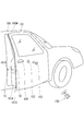
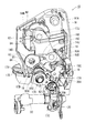
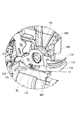
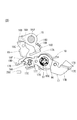
- the perspective view of the door lock device concerning the embodiment to which the present invention is applied A perspective view of part of a vehicle Back-side perspective view of the door lock device Side view of the door lock device seen from the sheet metal cover side Sectional view of the door lock apparatus which saw the AA cut surface in FIG.
- the door lock device 10 is generally shown in FIG. 1A, and has a structure in which a plurality of parts are assembled to a resin body 11.
- the resin body 11 is provided with a resin body main body 90 which is L-shaped as a whole when viewed from above as shown in FIG.
- the resin body main body 90 has first and second component storage portions 90A and 90B on both side surfaces adjacent to each other with the outer corner portion therebetween, and is disposed on the short side of the L-shape of the resin body main body 90 While the first resin cover 91 is assembled to the resin body main body 90 so as to close the side opening of the one component storage portion 90A, the side surface of the second component storage portion 90B disposed on the long side of the L shape of the resin body main body 90 A second resin cover 92 is assembled to the resin body 90 so as to close the opening.
- the first and second resin covers 91 and 92 and the resin body 90 constitute the resin body 11.
- the resin body 11 corresponds to the "case” of the present invention
- the resin body main body 90 corresponds to the "first case component” of the present invention
- the first resin cover 91 corresponds to the "third case” of the present invention. It corresponds to "2 case structure”.
- the first resin cover 91 is provided with a side protruding wall 91A that protrudes to the second resin cover 92 side, and the second resin cover 92 is attached to the resin body main body 90 first, and then the second resin cover The edge portion of the first resin cover 91 is assembled from the outside on the edge portion 92.
- a sheet metal cover 93 is fixed to the outer surface of the first resin cover 91 in a stacked state.
- a latch mechanism accommodation recess 91B is formed in a portion covered by the sheet metal cover 93, and a latch 13 and a ratchet 14 (see FIG. 12) which constitute the latch mechanism 10R are accommodated in the latch mechanism accommodation recess 91B.
- a groove main body 12A extending in the horizontal direction is formed in the back surface of the latch mechanism accommodation concave portion 91B, and in the portion facing the groove main body 12A of the sheet metal cover 93, the horizontal groove 12B. Is formed.
- the groove main body 12A and the horizontal groove 12B constitute a striker receiving groove 12, and one end of the striker receiving groove 12 is opened to the side projecting wall 91A to form a striker receiving opening 12K.
- a reinforcing plate 94 made of sheet metal is stacked on the inner surface of the first resin cover 91, and a pair of metal rotation support pins 13J, between the reinforcing plate 94 and the sheet metal cover 93, The sheet metal cover 93 and the reinforcing plate 94 are fixed to the first resin cover 91 by being connected by 14J.
- one rotation support pin 13J is disposed above the striker receiving groove 12, and the other rotation support pin 14J is disposed below the striker receiving groove 12.
- the latch 13 is rotatably supported by the upper rotation support pin 13J, and the ratchet 14 is rotatably supported by the lower rotation support pin 14J.
- the inner surface side to which the reinforcing plate 94 is fixed is accommodated in the first component accommodation portion 90A of the resin body main body 90, and in the back wall 90C of the first component accommodation portion 90A.
- the first resin cover 91 is fixed to the resin body main body 90 by tightening the holes 94N (see FIG. 6).
- the door lock device 10 is disposed inside the door 101 in a state where the sheet metal cover 93 is disposed on the inner surface of the end wall 101A of the door 101 and the second resin cover 92 is opposed to the interior wall side of the door 101 See Figure 5). Then, the bolt passed through the through hole provided in the end wall 101 A of the door 101 is tightened to the screw hole N 3 (see FIG. 1A) of the sheet metal cover 93 to fix the door lock device 10 to the door 101. Further, as shown in FIG. 1B, the striker receiving groove 12 of the door lock device 10 is superimposed on the notch groove 101B provided in the door 101. Then, the striker 15 provided on the inner surface of the door frame 100W of the vehicle 100 main body enters the striker receiving groove 12 from the striker receiving port 12K when the door 101 is closed.
- the latch 13 has first and second locking claws 13A and 13B parallel to each other, and a striker is received between the first and second locking claws 13A and 13B. It becomes part 13C. Then, a pivoting support pin 13J described above passes through a portion connecting the first and second locking claws 13A and 13B in the latch 13.
- the latch 13 is biased in the unlatching direction (clockwise direction in FIG. 12) by a torsion coil spring (not shown) provided between the latch 13 and the resin body 11. Then, when the door 101 is opened, the latch 13 is positioned at the unlatched position (the position shown in FIG. 12) by the abutment between the stopper abutting portion 13D provided in the latch 13 and the stopper 11X provided in the resin body 11. Be done.
- the first locking claw 13A retracts above the striker receiving groove 12 and the second locking claw 13B crosses the striker receiving groove 12 so that the open end of the striker receiving portion 13C is a striker. It faces the striker receiving port 12 K side of the receiving groove 12. Then, the striker 15 entering the striker receiving groove 12 is received in the striker receiving portion 13C, and the striker 15 pushes the second locking claw 13B to turn the latch 13 in the latch direction (counterclockwise direction in FIG. 12). Move. As a result, as shown in FIG. 13, the striker receiving port 12 K side of the striker receiving groove 12 from the striker receiving groove 12 is closed by the first locking claw 13 A, and the latch 13 is engaged with the striker 15.
- the ratchet 14 is rotatably supported by the rotation support pin 14J, and has the latch rotation restriction piece 14A and the stopper piece 14B protruding in opposite directions. Further, the ratchet 14 is biased in the counterclockwise direction in FIG. 12 by the torsion coil spring 14S. Thus, the ratchet 14 is normally positioned at the home position where the stopper piece 14B is in contact with the ratchet stopper 11D provided on the resin body 11.
- the latch rotation restricting piece 14A of the ratchet 14 interferes with the first locking claw 13A and the second locking claw 13B of the latch 13, and the ratchet 14 rotates clockwise from the home position and releases When it reaches the position, the latch rotation restricting piece 14A of the ratchet 14 and the first locking claw 13A and the second locking claw 13B of the latch 13 do not interfere with each other.
- the base end part of the spindle 97 mentioned later has penetrated the inner side of the coil part of the torsion coil spring 14S.
- the ratchet 14 engages with the latch 13 as follows. That is, when the door 101 is closed, the second locking claw 13B and the first locking claw 13A of the latch 13 which are turned by being pushed by the striker 15 sequentially depress the latch rotation restriction piece 14A of the ratchet 14 pass. Then, when the door 101 reaches a position where the soundproof member 101C (see FIG. 1B) between the door frame 100W and the door frame 100W is maximally crushed, the latch 13 receives the second locking from the latch rotation restricting piece 14A of the ratchet 14. The claws 13B reach the slightly separated overstroke position, whereby the ratchet 14 returns to the home position.
- the latch rotation restricting piece 14A of the ratchet 14 abuts against the first locking claw 13A of the latch 13 from the opposite side of the striker receiving portion 13C. 13 is positioned in the latch position. As a result, the rotation of the latch 13 in the latch releasing direction is restricted, and the door 101 is held in the fully closed state.
- the rotation restriction of the latch 13 by the ratchet 14 is either the outside door handle 104 provided on the exterior surface of the door 101 shown in FIG. 1B or the inside door handle (not shown) provided on the interior surface (inner surface) of the door 101. It can be released by the operation of The lift lever 16 shown in FIG. 14A is attached to the ratchet 14 so as to rotate integrally with the ratchet 14 in order to transmit the operation force from the outside door handle 104 and the inside door handle to the ratchet 14.
- the lift lever 16 is pivotally supported by a portion of the pivot support pin 14J which is sandwiched between the first resin cover 91 and the reinforcing plate 94.
- the striker receiving port 12K side (hereinafter referred to as “front side”) of the striker receiving groove 12 (see FIG. 12) from the pivoting support pin 14J Is referred to as “rear side”), and a second tilting arm 16C which protrudes rearward and obliquely downward from the rotation support pin 14J.
- the engagement projection 16K bent at a right angle from the upper edge of the second tilting arm 16C engages with the engagement hole 14C (see FIG.
- the first tilting arm 16A is provided with a tip contact portion 16B formed by bending its front end at a right angle, and the second tilting arm 16C is bent a rear end at a right angle and a second tilting arm An abutting projection 16D is provided which is projected obliquely downward on the front side of 16C.
- a support shaft 97 described later is disposed at an obliquely lower position on the rear side of the rotation support pin 14J, and the outside open lever 17 is provided outside the support projection 95 that constitutes the support shaft 97. Is rotatably supported.
- the outside open lever 17 corresponds to the “shaft fitting part” and the “pivotal lever” of the present invention, and protrudes to the rear side from the support arm 17A that protrudes to the front side from the support projection 95 and the support projection 95 And a control arm 17D.
- the outside open lever 17 is restricted in its rotation range as the upper edge of the operating arm 17D abuts against a stopper 90S (see FIGS. 7 and 8) integrally formed on the resin body 90.
- FIG. 14A and FIG. 14B It pivots between the home position shown in FIG. 14A and FIG. 14B and the operating position (see FIGS. 15A and 15B) rotated clockwise by a predetermined angle from the home position.
- the support arm 17A is inclined downward to the front (see FIG. 14A), and when the outside open lever 17 is in the operation position, the support arm 17A is horizontally oriented. And slightly inclined forward and downward (see FIG. 15A).
- the outside open lever 17 is biased toward the origin by the torsion coil spring 18 (see FIGS. 4, 6 and 14A) loosely fitted to the outside of the support projection 95 (support shaft 97).
- the outside open lever 17 has a locking projection 17X bent at a right angle in a direction parallel to the support shaft 97, and one spring end projecting laterally from the coil portion 18C of the torsion coil spring 18 The portion is locked to the locking projection 17X, and the other spring end portion is locked to the upper surface of the stopper portion 90S (see FIG. 7).
- the torsion coil spring 18 corresponds to the “shaft fitting part” in the present invention.
- an engagement hole 17B is penetratingly formed in a direction parallel to the axial direction of the support shaft 97.
- the engagement hole 17B has a shape in which a pair of chevrons 17T and 17T project toward the side approaching each other from two positions 180 degrees apart on the inner circumferential surface.
- the pressure receiving piece 17C is bent and protrudes from the lower edge of the front end of the support arm 17A. Then, when the inside door handle is operated, the inside open lever 20 described later abuts on the pressure receiving piece 17C from below to turn the outside open lever 17 from the home position to the operating position.
- the engagement portion 17E is bent at a right angle and protrudes toward the sheet metal cover 93 side.
- a through hole is formed in the engaging portion 17E, and the resin ring 17V is attached to the through hole.
- one end of a rod (not shown) is connected to the inside of the resin ring 17V, and the other end of the rod is connected to the outside door handle 104. Then, when the outside door handle 104 is operated, the engaging portion 17E is pushed downward, and the outside open lever 17 rotates from the home position to the operating position.
- the engagement protrusion 19A of the open link 19 is rotatably engaged with the engagement hole 17B of the outside open lever 17.
- the open link 19 has a shape extending in the vertical direction as a whole, and the engagement protrusion 19A described above protrudes in the axial direction of the support shaft 97 from the lower end.
- the open link 19 is restricted in its rotation range by the pair of chevrons 17T and 17T in the engagement hole 17B, and it is between the unlock position which has fallen to the front and the lock position which has fallen to the rear. Rotate.
- a torsion coil spring 29 (not shown in FIGS. 14B, 15A and 15B) is provided between the open link 19 and the outside open lever 17, and the open link 19 is unlocked by the torsion coil spring 29. It is biased by
- a push-up projection 19 C is bent in the axial direction of the support shaft 97 and protrudes.
- the push-up projection 19C is positioned below the tip contact portion 16B of the lift lever 16, and in this state the outside open lever 17
- the push-up projection 19C pushes up the tip contact portion 16B of the lift lever 16.
- the lift lever 16 pivots from the home position to the release position together with the ratchet 14 (see FIG. 13), the engagement between the ratchet 14 and the latch 13 is released, and the door 101 is opened.
- a lower end arm 19F protrudes forward from a lower end position of the open link 19, and an unlocking piece 19B is bent in the axial direction of the support shaft 97 and protrudes forward from the lower edge portion of the lower end arm 19F. Then, the open link 19 is switched from the unlock position to the lock position by pushing the lock release piece 19B upward by an active lever 25 described later.
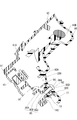
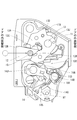
- the inside open lever 20, the active lever 25, the connecting bar 30, the relay lever 31 and the like shown in FIG. 16 are housed in the second component housing portion 90B of the resin body main body 90 described above.
- the surface facing the second resin cover 92 (the surface facing the front side of the sheet of FIG. 16) is referred to as the "outside" of the part, and the opposite side is the part "Inside" of the.
- the inside open lever 20 is rotatably supported by a support shaft 20J disposed at a position closer to the lower end on the right side in FIG. 16 of the second component storage unit 90B.
- the support shaft 20J is formed by fitting a shaft having a circular cross section and a cylindrical body protruding from the back surface of the second component storage portion 90B and the back surface of the second resin cover 92. The same applies to spindles 24J and 25J described later.
- a push-up contact portion 20B which extends from the support shaft 20J toward the central side in the lateral direction of the resin body 11 and whose tip is bent in the axial direction of the support shaft 20J
- a connecting projection 20C is provided, which protrudes downward from the portion 20B and whose tip is a wire locking portion 20A.
- the inside door handle is connected to the wire locking portion 20A via a wire (not shown). Then, by operating the inside door handle, the inside open lever 20 is pivoted from the home position to the working position, during which the push-up abutment portion 20B of the inside open lever 20 pushes up the pressure receiving piece 17C of the outside open lever 17 described above.
- the outside open lever 17 also pivots from the home position to the operating position. At this time, if the open link 19 is disposed at the unlock position, the door 101 is opened as described above, and if the open link 19 is disposed at the lock position, the door 101 is not opened.
- the active lever 25 is rotatably supported by a support shaft 25J located at the center in both the vertical and horizontal directions in the second component storage unit 90B.
- the active lever 25 has a first fan-shaped projection 25A projecting upward from the support shaft 25J, a sector-shaped second sector-shaped projection 25D extending obliquely downward to the left from the support shaft 25J, and a diagonal right side from the support shaft 25J. And a projecting active acting arm 25C.
- the tip of the active action arm 25C is opposed to the unlocking piece 19B of the open link 19 from below. Then, when the active lever 25 pivots from the unlock position to the lock position, as shown in the changes in FIG. 14B to FIG. 14A, the active action arm 25C pushes up the unlocking piece 19B to unlock the open link 19. Move from to the lock position.
- the wire connection piece 25E protrudes from the lower end of the second fan-shaped projection 25D.
- a lock operating portion provided on the inner surface of the door 101 is connected to the wire connection piece 25E via a wire (not shown). Then, by operating the lock operation unit, the active lever 25 can be switched between the unlock position and the lock position.
- the active lever 25 can be switched between the unlock position and the lock position by means of the in-vehicle centralized lock or the wireless key 108 (see FIG. 1B) as well as the lock operation portion on the inner surface of the door 101.
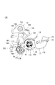
- the motor 22 shown in FIG. 16 is attached to the resin body 11.
- a worm gear 23 is fixed to a rotational output shaft of the motor 22 and a worm wheel 24 meshing with the worm gear 23 is rotatably supported on a support shaft 24 J provided on the resin body main body 90.
- a pair of rotation pressing protrusions 24A provided on the worm wheel 24 (only one rotation pressing protrusion 24A is shown in FIG. 16) and unevenness (not shown) provided on the inner surface of the first sector protrusion 25A.
- the power of the motor 22 can be transmitted to the active lever 25 to switch the active lever 25 between the locked position and the unlocked position.
- the active lever 25 can also be switched between the unlock position and the lock position by inserting the key 103 (see FIG. 1B) into the key cylinder 102 provided in the door 101 and performing key operation.
- the key connecting lever 32 connected to the key cylinder 102 is disposed on the back side of the resin body main body 90, and the pivoting axis passes through the resin body main body 90, as shown in FIG.
- the relay lever 31 disposed in the second component storage unit 90B are connected to the relay lever 31 disposed in the second component storage unit 90B.
- the relay lever 31 and the active lever 25 are connected by a connecting bar 30.
- the active lever 25 is also switched between the unlock position and the lock position by the operation of the key cylinder 102.
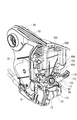
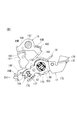
- the support structure 97 according to the present invention is applied to the support shaft 97 that rotatably supports the outside open lever 17.
- the structure of the support shaft 97 will be described below.
- the support projection 95 protrudes toward the back wall 90C (the front side of the sheet of FIG. 11) of the first component storage portion 90A.
- the support projection 95 includes a first cylindrical portion 95A protruding from the first resin cover 91, and a second cylindrical portion 95C protruding from a tip wall 95B closing the tip of the first cylindrical portion 95A. And have. Further, the second cylindrical portion 95C is disposed at a position eccentric downward with respect to the center of the first cylindrical portion 95A.
- the coil portion of the torsion coil spring 14S is loosely fitted to the outside of the first cylindrical portion 95A.
- a pivoting support cylinder 96 (corresponding to the “main shaft” of the present invention) is formed in a projecting manner on the back wall 90C of the first component housing 90A in the resin body main body 90.
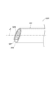
- the rotation support cylinder 96 has a cylindrical shape with an open tip, and a tip inclined surface 96F according to the present invention is formed on the open surface.
- the pivoting support cylinder 96 has an acute-angled wedge shape (shape like the tip of a bamboo basket) whose tip is diagonally cut off with respect to the central axis J1.
- the whole of the open surface 96 is constituted by a flat tip inclined surface 96 F diagonally crossing the central axis J 1 of the rotation support cylinder 96.
- the tip opening edge of the rotation support cylinder 96 is chamfered in a tapered shape, and the tip outer peripheral edge of the rotation support cylinder 96 is R-chamfered.
- the tip end inclined face 96F is an inclined face that constitutes the end face of the cylindrical wall of the rotation support cylinder 96, and the opening area on the inner side of the cylindrical wall is oblique to the central axis J1.
- a through hole 96A is formed at the center of a portion of the back wall 90C surrounded by the rotation support cylinder 96. Then, the first resin cover 91 is assembled to the resin body main body 90 in a state in which the rotation support cylinder 96 is inserted in the circular fitting hole 17H formed through the outside open lever 17 and the coil portion 18C of the torsion coil spring 18 The second cylindrical portion 95C corresponding to the “sub-shaft” of the present invention is inserted into the inside of the rotation support cylinder 96.
- the first resin cover 91 is fixed to the resin body main body 90 by tightening the screw N2, which is a self-tapping screw inserted into the through hole 96A, into the screw lower hole 95D penetrating the center of the second cylindrical portion 95C.
- the second cylindrical portion 95C and the rotation support cylinder 96 are integrated to form a support shaft 97 on which the outside open lever 17 and the torsion coil spring 18 are supported.
- the fitting hole 17H may not be circular, and may be, for example, a polygon circumscribing the outer peripheral surface of the rotation support cylinder 96.
- the center hole of the rotation support cylinder 96 may not be circular in cross section, and may be, for example, a polygonal cross section circumscribing the outer peripheral surface of the second cylindrical portion 95C.
- the second cylindrical portion 95C is fitted to the inside of the rotation support cylinder 96, and the resin body main body 90 and the first resin cover 91 are integrally fixed by the screws N1 and N2.
- various components such as the motor 22, the worm wheel 24, and the active lever 25 are assembled in the second component storage portion 90B of the resin body main body 90.
- the second resin cover 92 is put on the side opening of the second component storage section 90B, and the shaft constituting the spindles 20J, 24J, 25J and the cylindrical body (not shown) are engaged with each other in a concavo-convex manner.
- the outer edge portion of the resin body main body 90 and the outer edge portion of the second resin cover 92 are superimposed on each other, and they are joined by, for example, laser welding.
- the outside open lever 17 in which the open link 19 and the torsion coil spring 29 are integrally assembled in advance is assembled in the first component accommodating portion 90A of the resin body main body 90. That is, the rotary support cylinder 96 projecting from the back wall 90C of the first component storage portion 90A is inserted into the inside of the circular fitting hole 17H formed in the outside open lever 17 and these are fitted.
- a tip inclined surface 96F obliquely crossing the central axis J1 is formed on the open surface of the tip of the rotation support cylinder 96, and the tip of the rotation support cylinder 96 has an acute angle.
- the distal end inclined surface 96F of the pivoting support cylinder 96 is engaged with the outer edge portion of the pivoting support cylinder 96 also The edge of the hole 17H may hit halfway and the work will not be delayed. Specifically, even if the centers of the rotation support cylinder 96 and the fitting hole 17H are shifted at the beginning of the fitting operation, the centers gradually approach each other in the process of the subsequent fitting operation, and finally, as shown in FIG. As shown in 17C, the rotation support cylinder 96 and the fitting hole 17H are centered.
- the rotary support cylinder 96 is inserted into the coil portion 18C of the torsion coil spring 18.
- the one spring end of the torsion coil spring 18 is locked to the locking projection 17X of the outside open lever 17, and the other spring end is locked to the stopper 90S of the resin body 90.
- the torsion coil spring 18 is twisted and the outside open lever 17 is urged to the home position where it abuts against the stopper portion 90S, and the inner surface of the coil portion 18C of the torsion coil spring 18 is the outer surface of the rotation support cylinder 96.
- the coil portion 18C is disposed at a position where the center of the coil portion 18C is eccentric with respect to the center of the rotation support cylinder 96 while abutting a part. At this time, the coil portion 18C is disposed so as to abut the portion of the outer peripheral surface of the rotation support cylinder 96 opposite to the tip inclined surface 96F.
- the tip inclined surface 96F is formed on the opposite side to the portion to which the inner surface of the coil portion 18C approaches. By doing this, it is possible to prevent the coil portion 18C from coming off the rotation support cylinder 96 while keeping the length of the rotation support cylinder 96 short.
- the outside open lever 17 is assembled on the proximal end side of the rotation support cylinder 96, and the torsion coil spring 18 is assembled on the distal end side.
- the rotation support cylinder 96 may be lengthened. That is, since the support state of the outside open lever 17 becomes unstable when the front end inclined surface 96F is disposed inside the fitting hole 17H of the outside open lever 17, the whole front end inclined surface 96F is a fitting hole It is necessary to make it project from 17H, and the rotation support cylinder 96 becomes longer accordingly. In this respect, according to the configuration of the present embodiment, the length of the rotation support cylinder 96 can be kept short.
- the first resin cover 91 is assembled to the resin body main body 90. That is, the inner surface side (the reinforcing plate 94 side) of the first resin cover 91 is brought close to the back wall 90C of the first component storage portion 90A, and the entire inner surface side of the first resin cover 91 is in the first component storage portion 90A. And the edge of the side protruding wall 91A of the first resin cover 91 is overlapped with the edge of the second resin cover 92 from the outside. Then, the locking hole 91A1 formed in the edge of the side protruding wall 91A and the locking protrusion 92A formed in the edge of the second resin cover 92 are locked. Further, the second cylindrical portion 95C of the support projection 95 formed to project from the first resin cover 91 is inserted into the inside of the rotation support cylinder 96. As a result, the resin body 90 and the first resin cover 91 are temporarily fixed.
- the rotation support cylinder 96 is covered with the first resin cover 91 and it becomes difficult to visually recognize, but the tip of the rotation support cylinder 96 is the tip. Since the inclined surface 96F is provided, the fitting operation between the rotation support cylinder 96, which is difficult to visually recognize, and the second cylindrical portion 95C can be performed relatively easily.
- the tip of the second cylindrical portion 95C is Since it can be inserted into the inside of the rotation support cylinder 96 from the tip inclined surface 96F side, the fitting operation can be easily performed as compared with the one without the tip inclined surface 96F.
- the resin body main body 90 and the first resin cover 91 After temporarily fixing the resin body main body 90 and the first resin cover 91, finally, pass the screw N1 through the through hole 90D provided in the back wall 90C of the first component housing 90A and screw the screw N1 into the screw hole of the reinforcing plate 94.
- the screw N2 is inserted into the through hole 96A provided on the back wall 90C and is fixed to the screw lower hole 95D of the second cylindrical portion 95C inserted inside the rotary support cylinder 96 while being fixed to 94N.
- the first resin cover 91 is completely fixed to the resin body 90.
- the support shaft 97 is double-supported, and the support state of the outside open lever 17 and the torsion coil spring 18 is stabilized.
- the above is the manufacturing method of the door lock device 10.
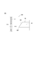
- the tip inclined surface 96F obliquely crossing the central axis J1 of the rotation support cylinder 96 is formed on the open surface of the tip of the rotation support cylinder 96, Before starting the fitting operation, it is not necessary to center the fitting hole 17H and the rotation support cylinder 96, and the tip end of the rotation support cylinder 96 sufficiently smaller than the fitting hole 17H and the cross section thereof The tip end portion 96P of the rotation support cylinder 96 can be easily passed through the fitting hole 17H simply by aligning the position 96P with the outline.
- the outer edge portion and the fitting hole of the tip inclined surface 96F of the turning support cylinder 96 can be inserted even in the process of the subsequent fitting work, as long as the foremost end 96P of the turning support cylinder 96 can be inserted into the fitting hole 17H. Since the operation does not get stuck due to the end of the edge 17H, the assembling workability of the outside open lever 17 with respect to the rotation support cylinder 96 can be sufficiently improved. Further, by providing the front end inclined surface 96F, the operation of fitting the second cylindrical portion 95C to the inside of the rotation support cylinder 96 can be performed relatively easily. That is, according to the present embodiment, it is possible to improve the assembling workability of the fitting parts (the outside open lever 17 and the second cylindrical portion 95C) with respect to the inside and outside of the rotation support cylinder 96.
- the outer peripheral edge of the tip of the cylindrical body to improve the assembling workability. It is also conceivable to provide a truncated cone-shaped guide surface at the tip opening edge, but since these guide surfaces can be formed only within the range of the wall thickness of the cylinder wall constituting the cylinder, it can be felt by the operator It is difficult to improve the workability to some extent.
- the assembling workability of the fitting component to the inside and outside of the rotation support cylinder 96 can be sufficiently improved.
- the fitting structure of the present invention is applied to the support shaft 97 that rotatably supports the outside open lever 17.
- the support shaft that rotatably supports the inside open lever 20 The fitting structure of the present invention may be applied to 20J, a spindle 24J rotatably supporting the worm wheel 24, and a spindle 25J rotatably supporting the active lever 25.
- the inside open lever 20, the worm wheel 24, and the active lever 25 correspond to the "shaft fitting part" of the present invention
- the inside open lever 20 and the active lever 25 correspond to the "pivotal lever" of the present invention.
- the tip inclined surface 96F formed at the tip of the rotation support cylinder 96 is configured as a flat surface, but the rotation support of the fitting structure 200V shown in FIG. 18A
- the tip inclined surface 96F1 may be configured by a curved surface that bulges to the tip side
- the tip inclined surface 96F2 is It may be composed of a curved surface that is recessed on the proximal side.
- the tip sloped surface 96F3 is formed of a curved curved surface that merges the tip sloped surfaces 96F1 and 96F2 shown in FIGS. 18A and 18B. It may be done.
- the tip inclined surface 96F may be configured of two or more inclined surfaces having different inclination angles with respect to the central axis J1.
- the entire open surface of the rotation support cylinder 96 is the tip inclined surface 96F.
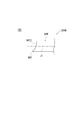
- the rotation support cylinder of the fitting structure 200Y shown in FIG. Like 96Y, a part of the open surface is a perpendicular surface 96G perpendicular to the central axis J1, and the remainder is a tip inclined surface 96F4 larger than half of the cross-sectional circular of the rotation support cylinder 96Y (hatched portion in FIG. ) May be used.
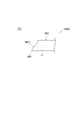
- the first end face 96K whose tip is smaller than half of the circular cross section of the pivoting support cylinder 96Z and its first end face 96K It may be divided into a stepped end surface 96L on the base end side to be stepped.
- the technical scope of the present invention is also provided with three or more end faces divided in a stepped shape, such as providing a third end face 96M shifted in a stepped shape on the base end side of the second end face 96L. include.
- the same effect as the fitting structure 200 of the above embodiment can be obtained. That is, it is not necessary to make the center of the fitting hole 17H of the outside open lever 17 and the center of the turning support cylinder 96Z coincide with each other at the beginning of the fitting operation, and turning of the fitting hole 17H and its cross section sufficiently smaller
- the first end face 96K of the rotary support cylinder 96Z can be easily passed through the fitting hole 17H simply by aligning the first end surface 96K of the support cylinder 96 with the about.
- the fitting operation is completed without any delay. Therefore, the workability of the fitting between the rotation support cylinder 96Z and the outside open lever 17 can be sufficiently improved. In addition, the fitting operation for fitting the second cylindrical portion 95C inside the rotation support cylinder 96Z can be easily performed.
- the pivoting support cylinder 96 having a cylindrical structure is exemplified as the "main shaft body" of the present invention, but as in the fitting structure 201 shown in FIG.
- An outside open lever 17 or an inside open lever 20 as a “pivotal lever” of the present invention is formed with a tip inclined face 98F according to the present invention at the tip of a rotary support column 98 having a real cylindrical structure. It may be configured to support the active lever 25 or the like, or may be configured to support the worm wheel 24 as the “shaft fitting part” of the present invention.
- the fitting structure 200 of the present invention is applied to the door lock device 10 for locking the door 101 for getting on and off the vehicle 100, but the door lock device for locking the back door
- the present invention may be applied to Also, the present invention may be applied to a locking device for locking a door or window sash of a building. Furthermore, the present invention may be applied to the fitting structure of the main shaft and the shaft fitting part provided in products other than the above-mentioned lock device.
Landscapes
- Lock And Its Accessories (AREA)
- Furniture Connections (AREA)
Abstract
Priority Applications (2)
| Application Number | Priority Date | Filing Date | Title |
|---|---|---|---|
| IN7722DEN2014 IN2014DN07722A (fr) | 2012-03-14 | 2013-03-04 | |
| CN201390000319.3U CN204212565U (zh) | 2012-03-14 | 2013-03-04 | 嵌合构造 |
Applications Claiming Priority (2)
| Application Number | Priority Date | Filing Date | Title |
|---|---|---|---|
| JP2012057778A JP6037496B2 (ja) | 2012-03-14 | 2012-03-14 | 嵌合構造 |
| JP2012-057778 | 2012-03-14 |
Publications (1)
| Publication Number | Publication Date |
|---|---|
| WO2013137040A1 true WO2013137040A1 (fr) | 2013-09-19 |
Family
ID=49160953
Family Applications (1)
| Application Number | Title | Priority Date | Filing Date |
|---|---|---|---|
| PCT/JP2013/055803 WO2013137040A1 (fr) | 2012-03-14 | 2013-03-04 | Structure de fixation |
Country Status (4)
| Country | Link |
|---|---|
| JP (1) | JP6037496B2 (fr) |
| CN (1) | CN204212565U (fr) |
| IN (1) | IN2014DN07722A (fr) |
| WO (1) | WO2013137040A1 (fr) |
Cited By (2)
| Publication number | Priority date | Publication date | Assignee | Title |
|---|---|---|---|---|
| US20150376918A1 (en) * | 2014-01-24 | 2015-12-31 | Mitsui Kinzoku Act Corporation | Vehicle door latch device |
| US10273724B2 (en) * | 2014-06-24 | 2019-04-30 | U-Shin Ltd. | Door lock device |
Families Citing this family (2)
| Publication number | Priority date | Publication date | Assignee | Title |
|---|---|---|---|---|
| JP6652709B2 (ja) * | 2016-07-15 | 2020-02-26 | 株式会社アンセイ | 車両用ドアロック装置 |
| JP6627671B2 (ja) * | 2016-07-15 | 2020-01-08 | 株式会社アンセイ | 車両用ドアロック装置 |
Citations (3)
| Publication number | Priority date | Publication date | Assignee | Title |
|---|---|---|---|---|
| JPS6256314B2 (fr) * | 1981-09-11 | 1987-11-25 | Ooi Seisakusho Kk | |
| JPH0325767U (fr) * | 1989-07-25 | 1991-03-15 | ||
| JPH09281587A (ja) * | 1996-04-18 | 1997-10-31 | Olympus Optical Co Ltd | フィルム装填装置 |
Family Cites Families (1)
| Publication number | Priority date | Publication date | Assignee | Title |
|---|---|---|---|---|
| JP3034103B2 (ja) * | 1991-11-26 | 2000-04-17 | 富士写真フイルム株式会社 | レンズ付きフイルムユニット用のフイルム従動スプロケット |
-
2012
- 2012-03-14 JP JP2012057778A patent/JP6037496B2/ja not_active Expired - Fee Related
-
2013
- 2013-03-04 CN CN201390000319.3U patent/CN204212565U/zh not_active Expired - Fee Related
- 2013-03-04 IN IN7722DEN2014 patent/IN2014DN07722A/en unknown
- 2013-03-04 WO PCT/JP2013/055803 patent/WO2013137040A1/fr active Application Filing
Patent Citations (3)
| Publication number | Priority date | Publication date | Assignee | Title |
|---|---|---|---|---|
| JPS6256314B2 (fr) * | 1981-09-11 | 1987-11-25 | Ooi Seisakusho Kk | |
| JPH0325767U (fr) * | 1989-07-25 | 1991-03-15 | ||
| JPH09281587A (ja) * | 1996-04-18 | 1997-10-31 | Olympus Optical Co Ltd | フィルム装填装置 |
Cited By (2)
| Publication number | Priority date | Publication date | Assignee | Title |
|---|---|---|---|---|
| US20150376918A1 (en) * | 2014-01-24 | 2015-12-31 | Mitsui Kinzoku Act Corporation | Vehicle door latch device |
| US10273724B2 (en) * | 2014-06-24 | 2019-04-30 | U-Shin Ltd. | Door lock device |
Also Published As
| Publication number | Publication date |
|---|---|
| JP6037496B2 (ja) | 2016-12-07 |
| CN204212565U (zh) | 2015-03-18 |
| IN2014DN07722A (fr) | 2015-06-26 |
| JP2013189823A (ja) | 2013-09-26 |
Similar Documents
| Publication | Publication Date | Title |
|---|---|---|
| US6913308B2 (en) | Forward facing rear door assembly for motor vehicles | |
| KR101334210B1 (ko) | 차량용 도어 래치 장치에서의 액추에이터 | |
| US8414038B2 (en) | Vehicle door latch structure | |
| US7530610B2 (en) | Door handle for vehicle | |
| JP5546521B2 (ja) | ドアロック装置 | |
| WO2013137040A1 (fr) | Structure de fixation | |
| JP4866668B2 (ja) | 車両用ドアラッチ装置 | |
| JP2008013935A (ja) | 車両用ドアラッチ装置 | |
| JP5743912B2 (ja) | ドアロック装置 | |
| CN108350708B (zh) | 锁止装置 | |
| WO2013105408A1 (fr) | Dispositif de serrure de portière | |
| JP2016089349A (ja) | 車両用ドアラッチ装置および車両用ドアラッチ装置の組立方法 | |
| JP2007270573A (ja) | 車両用ドアロック装置 | |
| JP5995591B2 (ja) | ドアロック装置 | |
| JP5743911B2 (ja) | ドアロック装置 | |
| JP4936381B2 (ja) | 自動車用ドアハンドル装置 | |
| JP4921219B2 (ja) | 車両用ドアクローザ装置 | |
| JP4917919B2 (ja) | 自動車の開閉体用ロック装置 | |
| JP2005120769A (ja) | 扉用プッシュプル錠 | |
| WO2021002073A1 (fr) | Dispositif d'ouverture de porte | |
| JP3912714B2 (ja) | 車両用ロック装置 | |
| JP6566005B2 (ja) | 車両のドア構造およびその組立方法 | |
| JPH11159212A (ja) | 車両用ドアロック装置 | |
| JP2006214081A (ja) | 錠装置 | |
| JP2016205047A (ja) | 車両用ドアハンドル装置 |
Legal Events
| Date | Code | Title | Description |
|---|---|---|---|
| WWE | Wipo information: entry into national phase |
Ref document number: 201390000319.3 Country of ref document: CN |
|
| 121 | Ep: the epo has been informed by wipo that ep was designated in this application |
Ref document number: 13761345 Country of ref document: EP Kind code of ref document: A1 |
|
| NENP | Non-entry into the national phase |
Ref country code: DE |
|
| WWE | Wipo information: entry into national phase |
Ref document number: IDP00201406152 Country of ref document: ID |
|
| 122 | Ep: pct application non-entry in european phase |
Ref document number: 13761345 Country of ref document: EP Kind code of ref document: A1 |