WO2014125605A1 - 二次電池モジュール - Google Patents
二次電池モジュール Download PDFInfo
- Publication number
- WO2014125605A1 WO2014125605A1 PCT/JP2013/053615 JP2013053615W WO2014125605A1 WO 2014125605 A1 WO2014125605 A1 WO 2014125605A1 JP 2013053615 W JP2013053615 W JP 2013053615W WO 2014125605 A1 WO2014125605 A1 WO 2014125605A1
- Authority
- WO
- WIPO (PCT)
- Prior art keywords
- secondary battery
- battery module
- stacking direction
- width direction
- battery
- Prior art date
Links
Images


Classifications
-
- H—ELECTRICITY
- H01—ELECTRIC ELEMENTS
- H01M—PROCESSES OR MEANS, e.g. BATTERIES, FOR THE DIRECT CONVERSION OF CHEMICAL ENERGY INTO ELECTRICAL ENERGY
- H01M10/00—Secondary cells; Manufacture thereof
- H01M10/04—Construction or manufacture in general
- H01M10/0481—Compression means other than compression means for stacks of electrodes and separators
-
- H—ELECTRICITY
- H01—ELECTRIC ELEMENTS
- H01M—PROCESSES OR MEANS, e.g. BATTERIES, FOR THE DIRECT CONVERSION OF CHEMICAL ENERGY INTO ELECTRICAL ENERGY
- H01M50/00—Constructional details or processes of manufacture of the non-active parts of electrochemical cells other than fuel cells, e.g. hybrid cells
- H01M50/20—Mountings; Secondary casings or frames; Racks, modules or packs; Suspension devices; Shock absorbers; Transport or carrying devices; Holders
- H01M50/204—Racks, modules or packs for multiple batteries or multiple cells
- H01M50/207—Racks, modules or packs for multiple batteries or multiple cells characterised by their shape
- H01M50/209—Racks, modules or packs for multiple batteries or multiple cells characterised by their shape adapted for prismatic or rectangular cells
-
- H—ELECTRICITY
- H01—ELECTRIC ELEMENTS
- H01M—PROCESSES OR MEANS, e.g. BATTERIES, FOR THE DIRECT CONVERSION OF CHEMICAL ENERGY INTO ELECTRICAL ENERGY
- H01M50/00—Constructional details or processes of manufacture of the non-active parts of electrochemical cells other than fuel cells, e.g. hybrid cells
- H01M50/20—Mountings; Secondary casings or frames; Racks, modules or packs; Suspension devices; Shock absorbers; Transport or carrying devices; Holders
- H01M50/289—Mountings; Secondary casings or frames; Racks, modules or packs; Suspension devices; Shock absorbers; Transport or carrying devices; Holders characterised by spacing elements or positioning means within frames, racks or packs
- H01M50/291—Mountings; Secondary casings or frames; Racks, modules or packs; Suspension devices; Shock absorbers; Transport or carrying devices; Holders characterised by spacing elements or positioning means within frames, racks or packs characterised by their shape
-
- Y—GENERAL TAGGING OF NEW TECHNOLOGICAL DEVELOPMENTS; GENERAL TAGGING OF CROSS-SECTIONAL TECHNOLOGIES SPANNING OVER SEVERAL SECTIONS OF THE IPC; TECHNICAL SUBJECTS COVERED BY FORMER USPC CROSS-REFERENCE ART COLLECTIONS [XRACs] AND DIGESTS
- Y02—TECHNOLOGIES OR APPLICATIONS FOR MITIGATION OR ADAPTATION AGAINST CLIMATE CHANGE
- Y02E—REDUCTION OF GREENHOUSE GAS [GHG] EMISSIONS, RELATED TO ENERGY GENERATION, TRANSMISSION OR DISTRIBUTION
- Y02E60/00—Enabling technologies; Technologies with a potential or indirect contribution to GHG emissions mitigation
- Y02E60/10—Energy storage using batteries
-
- Y—GENERAL TAGGING OF NEW TECHNOLOGICAL DEVELOPMENTS; GENERAL TAGGING OF CROSS-SECTIONAL TECHNOLOGIES SPANNING OVER SEVERAL SECTIONS OF THE IPC; TECHNICAL SUBJECTS COVERED BY FORMER USPC CROSS-REFERENCE ART COLLECTIONS [XRACs] AND DIGESTS
- Y02—TECHNOLOGIES OR APPLICATIONS FOR MITIGATION OR ADAPTATION AGAINST CLIMATE CHANGE
- Y02P—CLIMATE CHANGE MITIGATION TECHNOLOGIES IN THE PRODUCTION OR PROCESSING OF GOODS
- Y02P70/00—Climate change mitigation technologies in the production process for final industrial or consumer products
- Y02P70/50—Manufacturing or production processes characterised by the final manufactured product
Definitions
- the present invention relates to a secondary battery module having a plurality of battery cells and capable of releasing and storing electric energy.
- Patent Document 1 discloses a structure in which a battery stack and an elastic body are housed in a space formed by combining an L-shaped first frame and a second frame.
- the secondary battery module described in Patent Document 1 has a structure in which a plurality of prismatic secondary batteries in a stacked state and an elastic body are fastened and fixed by a pair of frames. For this reason, the dimensional accuracy in the stacking direction of the battery is deteriorated, and the pressing load of the elastic body may vary.
- the secondary battery module is stacked such that a plurality of secondary batteries having a flat rectangular battery container are opposed so that wide side surfaces having a large area among the side surfaces of the battery container face each other.
- a battery stack, a pair of end plates disposed opposite to one side and the other side in the stacking direction of the battery stack, and one side and the other in the cell width direction perpendicular to the stacking direction of the battery stack One end of the cell width direction on one side and the other side, respectively, and one end is engaged with the end plate on the one side in the stacking direction and the other end is on the end plate on the other side in the stacking direction.
- a pair of side frames to be engaged, an end surface on one side in the stacking direction of the battery stack, and an end plate on one side in the stacking direction, and an elastic body that presses the battery stack in the stacking direction are provided. That.
- (A) is a schematic diagram which shows the form pressed in a 1st attitude
- (b) is a schematic diagram which shows the form pressed in a 2nd attitude
- (A) is a perspective view which shows the leaf
- (b) is provided in the secondary battery module which concerns on the modification of 2nd Embodiment. The perspective view which shows a leaf
- FIG.12 (A) is a perspective view which shows the leaf
- (A) is a schematic diagram which shows the pressing position of the leaf
- plate spring provided in the secondary battery module which concerns on a modification.
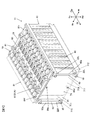
- FIG. 1 is a perspective view showing an appearance of the secondary battery module 11 according to the first embodiment
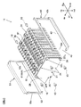
- FIG. 2 is a perspective view showing a state where the side frames 41 and 51 are removed from the secondary battery module 11.
- FIG. 3 is a perspective view showing the configuration of the secondary battery module 11, and
- FIG. 4 is a plan view of the secondary battery module 11.
- the secondary battery module 11 includes a plurality of rectangular batteries 61, a cell holder that holds each rectangular battery 61, a pair of end plates 21 and 31, and a pair of side frames 41 and 51. It is comprised including.
- FIG. 5 is a perspective view showing the external appearance of the prismatic battery 61.
- the rectangular battery 61 includes a battery container composed of a rectangular parallelepiped battery can 62 and a rectangular flat battery cover 63, and charging / discharging elements are accommodated in the battery can 62 via an insulating case.
- the opening 62 ⁇ / b> A is sealed by the battery lid 63.
- a positive terminal 64 and a negative terminal 65 project from the battery lid 63.
- the positive electrode terminal 64 and the negative electrode terminal 65 are terminals for outputting power generated by the charge / discharge element in the battery can 62 to the outside and charging the charge / discharge element with the power generated outside.
- the battery can 62 is made of metal and has a depth dimension larger than the dimension of the short side of the opening by a deep drawing method.
- the battery can 62 is a flat container having a bottomed rectangular parallelepiped shape, and is formed by a wide side surface 62W having a large area, a narrow side surface 62N having a small area, and a bottom surface (can bottom surface) 62B which is a bottom surface of the container.
- An opening 62A is provided.
- the battery lid 63 is fixed to the opening 62A of the battery can 62 by a laser beam welding method.
- the battery lid 63 is formed with a through hole through which the positive electrode terminal 64 and the negative electrode terminal 65 are inserted.
- the battery lid 63 is provided with a liquid injection hole 63A and a safety valve 63B.
- the liquid injection hole 63A is sealed by laser beam welding of the liquid injection stopper after the electrolytic solution is injected into the battery can 62.
- the safety valve 63B is cleaved when the pressure in the battery can 62 rises above a predetermined value, and releases the pressure in the battery can 62.
- the plurality of prismatic batteries 61 are stacked so that the wide side surfaces 62W face each other to constitute a battery stack 60.
- the plurality of prismatic batteries 61 constituting the battery stack 60 are secured in a state of being stacked by a pair of end plates 21 and 31 and a pair of side frames 41 and 51.
- the pair of end plates 21 and 31 are disposed to face the one side Df and the other side Dr in the stacking direction of the battery stack 60.
- the pair of side frames 41 and 51 are disposed to face the one side Wl and the other side Wr, respectively, in the cell width direction orthogonal to the stacking direction of the battery stack 60.
- the pair of side frames 41 and 51 are engaged with the end plate 21 on one side Df in the stacking direction on one side Wl and the other side Wr in the cell width direction, and the end plate 31 on the other side Dr in the stacking direction. And the other end is engaged.
- FIG. 6 is a perspective view of the end plates 21 and 31.
- the end plate 21 on the one side Df in the stacking direction and the end plate 31 on the other side Dr in the stacking direction have the same configuration.
- the end plates 21 and 31 each have a rectangular plate shape having a predetermined thickness and a rectangular shape having substantially the same size as the end surface of the battery stack 60 in the stacking direction.
- the outer surface of the end plate 21 has an end on one side Wl in the cell width direction and a protrusion 22L projecting on one side Df in the stacking direction at each end in the cell height direction, and an end on the other side Wr in the cell width direction.
- a protrusion 22R that protrudes to one side Df in the stacking direction at both ends in the cell height direction.
- Protrusions 32R projecting to the other side Dr in the stacking direction are provided at the ends of Wr and at both ends in the cell height direction.
- the projecting portions 22L and 32L have a columnar shape and have a shape that is substantially the same as the thickness of the side frame 41.
- the projecting portions 22R and 32R have a columnar shape and have a shape that has substantially the same projecting dimension as the plate thickness of the side frame 51.
- the protrusions 22L and 32L and the protrusions 22R and 32R may have a cubic shape.
- it is desirable that the end portions are inclined so that end edge portions 42a, 42b, 52a, 52b of openings of side frames 41, 51 described later can be easily inserted.
- the end plate 21 is provided with a pin hole 24 and a screw hole (fastening hole) 26.
- the end plate 31 is provided with a pin hole 34 and a screw hole (fastening hole) 36.
- the screw holes 26 and 36 are for fastening the fixing screws 10 that fix the side frames 41 and 51 to the end plates 21 and 32.
- the screw holes 26 are provided at the four corners of the end plate 21, and the screw holes 36 are provided at the four corners of the end plate 31.
- the pin hole 24 is a through hole into which guide pins 86u and 86d of an end cell holder 81f described later are inserted.
- the pin holes 24 are provided at both end portions in the cell height direction at the center position in the cell width direction of the end plate 21.
- the pin hole 34 is a through hole into which guide pins 86u and 86d of an end cell holder 81r described later are inserted.
- the pin hole 34 is provided at each of both end portions in the cell height direction at the center position in the cell width direction of the end plate 31. As will be described later, when the guide pins 86u and 86d of the end cell holder 81r are omitted, the pin hole 34 can be omitted.
- the side frame 41 on one side Wl in the cell width direction has a protrusion 22L (see FIGS. 2 and 6A) on the end plate 21 on one side Df in the stacking direction
- the projections 22L and 32L on the one side Wl in the cell width direction of the end plates 21 and 31 are opened by opening between the projections 32L (see FIG. 6B) of the end plate 31 on the other side Dr in the direction.
- Each has an opening 42 into which each is inserted.
- the side frame 51 on the other side Wr in the cell width direction includes the protrusion 22R (see FIGS. 2 and 6A) of the end plate 21 on the one side Df in the stacking direction and the end plate on the other side Dr in the stacking direction.
- 31 is opened between the protrusion 32R on the other side Wr in the cell width direction (see FIG. 6B), and the protrusions 22R and 32R on the other side Wr in the cell width direction of the end plates 21 and 31.
- Each has an opening 52 into which each is inserted.
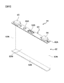
- FIG. 7 is a perspective view of the side frame 51 (41). In the following description, only the configuration of the side frame 51 will be described, and the configuration of the side frame 41 is the same as that of the side frame 51. Description is omitted.
- the side frame 51 (41) is made of a plate member having a substantially rectangular shape in plan view and facing the end surface of the battery stack 60 in the cell width direction.
- the side frame 51 (41) has a constant height dimension substantially equal to the cell height dimension of the battery stack 60 and a size extending between the pair of end plates 21 and 31.
- the side frame 51 (41) has a rectangular flat plate portion 50 (40) that is in contact with the cell holder, and both longitudinal ends of the flat plate portion 50 (40) are bent 90 degrees inward in the cell width direction.
- Flanges 53 (43) and ribs 56 (46) formed by bending both ends in the short direction of the flat plate portion 50 (40) 90 degrees outward in the cell width direction. In some cases, the rib 56 (46) may be omitted.
- the side frame 51 (41) is provided with an opening 52 (42) having a certain height and opening from one end to the other end.
- the opening 52 (42) extends from one flange 53 (43) along the shape of the side frame 51 (41) so that the end surface of the battery stack 60 on the other side Wr in the cell width direction can be exposed.
- the other flange 53 (43) is opened.
- the opening 52 (42) includes an upper edge portion 52c (42c) and a lower edge portion 52d (42d) formed from the flat plate portion 50 (40) to the flange 53 (43), and a pair of flanges 53 (43). And edge portions 52a (42b) and 52b (42a).
- the upper edge portion 52c (42c) and the lower edge portion 52d (42d) extend in parallel to each other across the one end portion and the other end portion.
- the edge part 52a (42b) and the edge part 52b (42a) extend in parallel to each other along the cell height direction at one end part and the other end part.
- the pair of edge portions 52a and 52b of the opening 52 are opposed to each other at the inner positions in the cell width direction of the protrusions 22R and 32R on the other side Wr of the end plates 21 and 31 in the cell width direction.
- the pair of edge portions 42a and 42b of the opening 42 are in contact with each other at the inner positions in the cell width direction of the protrusions 22L and 32L on one side Wl of the end plates 21 and 31 in the cell width direction.
- the pair of flanges 53 (43) are bent in the same direction at one end and the other end of the side frame 51 (41), respectively, and the outer end surface of the end plate 21 on the one side Df in the stacking direction and the other in the stacking direction.
- the side Dr is configured to face the outer end surface of the end plate 31.
- each flange 53 (43) a through hole 55 (45) through which the fixing screw (fastening member) 10 is inserted is formed.
- the through hole 55 (45) is arranged so as to overlap the screw holes 26 and 36 of the end plates 21 and 31 with the side frame 51 (41) attached, and the fixing screw 10 is inserted from the outside in the stacking direction to the screw hole. 26 and 36 can be screwed.
- the side frames 51 and 41 may be fastened and fixed using bolts, rivets, caulking, or the like instead of using the fixing screws 10.
- the pair of ribs 56 (46) extends along the upper end and the lower end of the side frame 51 (41), and the cross section viewed from one side Df in the stacking direction is substantially U-shaped.
- the pair of ribs 56 (46) can improve the rigidity of the side frame 51 (41) and can prevent the side frame 51 (41) from being deformed. Accordingly, it is possible to prevent the engagement with the protrusions 22R (22L) and 32R (32L) of the end plates 21 and 31 due to the twist of the side frame 51 (41) or the like.
- the battery stack 60 is disposed between the end plate 21 and the end plate 31, and a later-described leaf spring 71 is disposed between the end plate 21 and the battery stack 60. Is done.
- the leaf spring 71 is disposed in an elastically deformed state so as to be compressed, and applies a pressing force in the stacking direction so as to separate the end plate 21 and the battery stack 60.
- the end plates 21 and 31 are regulated in the stacking direction by the flanges 43 at both ends of the side frame 41 and the flanges 53 at both ends of the side frame 51. Therefore, the dimension in the stacking direction of the secondary battery module 11 is determined by the dimension between the flanges 43 of the side frame 41 and the dimension between the flanges 53 of the side frame 51.
- the end plate 21 and the end plate 31 move in directions away from each other in the stacking direction due to the pressing force in the stacking direction by the leaf springs 71. Therefore, the battery stack 60 is secured from both sides in the stacking direction.
- the plurality of cell holders include a pair of end cell holders 81f and 81r interposed between the end plates 21 and 31 and the square battery 61, and a square battery 61 on one side Df in the stacking direction.
- An intermediate cell holder 91 is provided between the pair of end cell holders 81f and 81r, and a plurality of intermediate cell holders 91 that are connectable in the stacking direction are interposed between the square battery 61 on the other side Dr in the stacking direction.
- the prismatic battery 61 is held in a state of being sandwiched from both sides in the stacking direction by connecting the end cell holders 81f and 81r, the intermediate cell holder 91, and the intermediate cell holders 91 to each other in the stacking direction.
- the end cell holders 81f and 81r are respectively inserted into the openings 42 and 52 of the pair of side frames 41 and 51 on one side Wl and the other side Wr in the cell width direction of the battery stack 60, respectively.
- the convex portion 84C is provided at the center position in the cell height direction, and the flat plate portions 40, 50 of the side frames 41, 51 are respectively provided on one side Hu in the cell height direction and the other side Hd in the cell height direction of the convex portion 84C.
- the contact surface portions 84Bu and 84Bd that contact the surface are provided.
- Each of the intermediate cell holders 91 is inserted into each of the openings 42 and 52 of the pair of side frames 41 and 51 on one side Wl and the other side Wr of the battery stack 60 in the cell width direction, and the pair of side frames 41 and 51. It has the convex part 94C engaged with.
- the convex portion 94C is provided at a central position in the cell height direction, and the flat plate portions 40, 50 of the side frames 41, 51 are respectively provided on one side Hu of the convex portion 94C in the cell height direction and the other side Hd in the cell height direction.
- the contact surface portions 94Bu and 94Bd that contact the surface are provided.
- the contact surface portions 84Bu and 84Bd are in contact with the side frames 41 and 51, thereby restricting movement of the end cell holders 81f and 81r in the cell width direction.
- the contact surface portions 94Bu and 94Bd are in contact with the side frames 41 and 51, thereby restricting the movement of the intermediate cell holder 91 in the cell width direction.
- the convex portion 84C is inserted into the openings 42 and 52 of the side frames 41 and 51, the upper end portion of the convex portion 84C is opposed to the upper end portions 42c and 52c of the opening portions 42 and 52, and the lower end of the convex portion 84C.
- the portion faces the lower end portions 42d and 52d of the openings 42 and 52, and restricts movement of the end cell holders 81f and 81r in the cell height direction.
- FIG. 8 is a perspective view of the end cell holder 81f on one side Df in the stacking direction.
- the end cell holder 81 f has a contact portion 82 that contacts the wide side surface 62 ⁇ / b> W of the prismatic battery 61.
- a frame portion 83 that rises perpendicularly from the contact portion 82 is provided at the periphery of the contact portion 82.
- the convex portions 84C and the contact surface portions 84Bu and 84Bd described above are provided on the side surfaces of both ends of the frame portion 83 in the cell width direction.
- One surface of the contact portion 82 is a contact surface that contacts the wide side surface 62 ⁇ / b> W of the prismatic battery 61, and the other surface is a spring receiving surface 82 a that contacts the leaf spring 71.
- a pair of guide pins 86u and 86d are provided on the spring receiving surface 82a. The pair of guide pins 86u and 86d are provided so as to be spaced apart from each other in the cell height direction and extend in the stacking direction.
- the end cell holder 81r on the other side Dr in the stacking direction has the same configuration as the end cell holder 81f on the one side Df in the stacking direction. Since the leaf spring 71 is not disposed between the end cell holder 81r on the other side Dr in the stacking direction and the end plate 31, the guide pins 86u and 86d may be omitted. Note that the guide pins 86u and 86d are preferable because the end pins 31 can be easily positioned by inserting the guide pins 86u and 86d into the pin holes 34 of the end plate 31.
- a leaf spring 71 is disposed between the end surface of the battery stack 60 on one side Df in the stacking direction and the end plate 21 on the one side Df in the stacking direction.
- the leaf spring 71 is an elastic body that applies an elastic force to the rectangular battery 61 and presses the battery stack 60 in the stacking direction via the end cell holder 81f.
- FIG. 9 is a perspective view showing a leaf spring 71 provided in the secondary battery module according to the first embodiment.
- the leaf spring 71 is made of a metal material and has a rectangular flat plate portion 710, a pair of inclined portions 711 extending from both ends of the flat plate portion 710 in the cell width direction, and a pair of And curved end portions 712 provided at respective end portions of the inclined portion 711.
- the flat plate portion 710 has a flat contact surface 710 a with which one surface is in contact with the end surface of the end plate 21.
- a pair of pin holes 716 through which the above-described guide pins 86u and 86d of the end cell holder 81f are inserted are provided at both ends in the cell height direction at the center position in the cell width direction of the flat plate portion 710.
- the pair of inclined portions 711 are bent from the both edges in the cell width direction of the flat plate portion 710 toward the other side Dr in the stacking direction, and inclined with respect to the flat plate portion 710. It is extended. As shown in FIG. 4, the pair of inclined portions 711 are inclined so that the distance between the inclined portions 711 in the cell width direction becomes wider as approaching the tip in plan view.
- the tip of the inclined portion 711 is curved toward the one side Df in the stacking direction to form a curved end 712.
- Each of the pair of curved end portions 712 is provided along the narrow side surface 62N, that is, parallel to the cell height direction.
- the surface of the curved end portion 712 on the other side Dr in the stacking direction is a contact curved surface portion 712a that contacts the end cell holder 81f.
- the leaf spring 71 is disposed in an elastically deformed state, that is, in a compressed state so that the distance between the flat plate portion 710 and the curved end portion 712 approaches, and separates the end plate 21 and the end cell holder 81f. Generate elastic force in the direction.
- the elastic force of the leaf spring 71 is transmitted to the prismatic battery 61 located on the outermost side of the stacking direction one side Df among the plurality of prismatic batteries 61 constituting the battery stack 60 through the end cell holder 81f.
- the prismatic battery 61 positioned on the outermost side in the stacking direction one side Df is referred to as a first prismatic battery 61A.
- the end cell holder 81f is made of a resin material.
- the end cell holder 81f is pressed by the contact curved surface portion 712a of the curved end portion 712, the pressed portion, that is, the vicinity of both ends in the cell width direction of the end cell holder 81f is the other side Dr in the stacking direction. It is elastically deformed so as to swell toward the surface. As a result, the elastic force of the leaf spring 71 is transmitted to two locations near both ends in the cell width direction on the wide side surface 62W of the first rectangular battery 61A through the end cell holder 81f (FIG. 10 (a )reference).
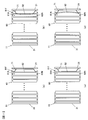
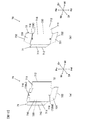
- FIG. 10 is a diagram schematically showing a pressing position 66s of the leaf spring 71 against the wide side surface 62W of the first rectangular battery 61A.
- the pressing position 66s of the leaf spring 71 shown in FIG. 9 is near the corners (both ends in the cell width direction) of the battery container on the wide side surface 62W of the first prismatic battery 61A, as shown in FIG. It becomes.
- the pressing position 66s with respect to the first rectangular battery 61A is As shown in FIG.
- the pressing position 66s in the first posture takes into consideration the position of the charge / discharge element accommodated in the battery case, and when the wide side surface 62W is viewed from the front, it is between the narrow side surface 62N and the charge / discharge element. It is preferable to set.
- the plate spring 71 is rotated 180 degrees around an axis parallel to the cell height direction, the flat plate portion 710 is brought into contact with the end cell holder 81f, and the curved end portion 712 is brought into contact with the end plate 21.
- the pressing position 66c of the leaf spring 71 against the wide side surface 62W is the central portion excluding the vicinity of the corner of the battery case on the wide side surface 62W.
- the leaf spring 71 is configured to be installable in either a form that presses in the first attitude or a form that presses in a second attitude different from the first attitude.
- Elastic force is applied to the battery stack 60 at a position different from the first posture.
- FIG. 11 is an explanatory diagram comparing the form of pressing in the first position and the form of pressing in the second position.
- the rectangular battery 61 includes a battery that easily swells due to charge and discharge and a battery that does not easily swell.
- FIG. 11A is a schematic diagram when the battery stack 60 composed of the rectangular batteries 61 that are difficult to swell due to charging / discharging is pressed in the first posture
- FIG. 11B is a rectangular battery that is difficult to swell due to charging / discharging. It is a schematic diagram when the battery laminated body 60 comprised by 61 is pressed with a 2nd attitude
- FIG. 11C is a schematic diagram when the battery stack 60 composed of the rectangular batteries 61 that easily swell due to charging / discharging is pressed in the second position
- FIG. 11D is a rectangular battery that easily swells due to charging / discharging. It is a schematic diagram when the battery laminated body 60 comprised by 61 is pressed in the 1st attitude
- the pressing load of the leaf spring 71 acting on the wide side surface 62W of the first rectangular battery 61A is received by the side plate constituting the narrow side surface 62N. For this reason, when a pressing load is applied to the rectangular battery 61 that does not easily swell due to charge / discharge, the amount of deflection can be suppressed as the pressing position is closer to the side plate that forms the narrow side surface 62N that serves as a fulcrum on the wide side surface 62W.
- the mode of pressing in the first posture (see FIGS. 10A and 11A) is used.
- an appropriate pressing force can be applied to the battery stack 60.
- the battery stack is adopted by adopting a mode of pressing in the second posture (see FIGS. 10B and 11B). Appropriate pressing force can be applied to 60.
- the secondary battery module 11 includes a battery stack 60, a pair of end plates 21 and 31 disposed to face the stacking direction one side Df and the other side Dr of the battery stack 60, and the cell width direction. Between the pair of side frames 41 and 51 disposed to face the one side Wl and the other side Wr, the end surface on one side Df in the stacking direction of the battery stack 60, and the end plate 21 on the one side Df in the stacking direction And a leaf spring 71 that presses the battery stack 60 in the stacking direction.
- the pair of side frames 41 and 51 are engaged with the end plate 21 on one side Df in the stacking direction on one side Wl and the other side Wr in the cell width direction, and the end plate 31 on the other side Dr in the stacking direction. And the other end is engaged. Therefore, the dimension in the stacking direction of the secondary battery module 11 is set by the side frames 41 and 51. For this reason, favorable dimensional accuracy can be obtained in the stacking direction. As a result, it is possible to suppress variations in the pressing load that acts on the battery stack 60 from the leaf spring 71.
- the battery stack is sandwiched between the L-shaped first frame and the second frame, and the first frame and the second frame are Since it is set as the structure which adjusts a space
- the dimension in the stacking direction is determined by the side frames 41 and 51, it is not necessary to adjust the position in the stacking direction dimension, a good dimensional accuracy can be easily obtained, and an appropriate pressing load is applied to the battery stack. It can be applied to the body 60.
- Protrusions 22L and 32L projecting in the stacking direction on the one side Wl in the cell width direction are provided on the outer surfaces of the end plates 21 and 31, and projecting in the stacking direction on the other side Wr in the cell width direction.
- Protrusions 32L and 32R are provided.
- the protrusions 22L and 32L on one side Wl in the cell width direction are inserted into the flanges 43 at both ends engaged with the pair of end plates 21 and 31, respectively.
- An opening is provided, and edge portions 42a and 42b of the opening are engaged with the inner side in the cell width direction of the protrusions 22L and 32L on one side Wl in the cell width direction.
- the protrusions 22R and 32R on the other side Wr in the cell width direction are inserted into the flanges 53 at both ends engaged with the pair of end plates 21 and 31, respectively.
- An opening is provided, and edge portions 52a and 52b of the opening are engaged with the inner side in the cell width direction of the protrusions 22R and 32R on the other side Wr in the cell width direction.
- the leaf spring 71 Since the leaf spring 71 is disposed between the battery stack 60 and the end plate 21, the end plates 21 and 31 are pressed against the flanges 43 and 53 of the side frames 41 and 51 by the elastic force of the leaf spring 71. . Therefore, the side frames 41 and 51 can be self-fastened by the elastic force of the leaf spring 71 before attaching the fixing screw 10 during the assembly work. Since the projections 22L, 32L, 22R, and 32R of the end plates 21 and 31 are engaged with the end edges 42a, 42b, 52a, and 52b, the side frames 41 and 51 are prevented from being displaced and dropped off easily. Can be positioned. As a result, assembly work can be easily performed.
- FIG. 12A is a perspective view showing a leaf spring assembly 75 provided in the secondary battery module according to the second embodiment
- FIG. 13A is a perspective view showing a leaf spring for combination.
- FIG. 14A is a diagram schematically showing the pressing positions 66s and 66d of the leaf spring assembly 75.
- a single leaf spring 71 is used at two locations in the vicinity of the corner of the battery container that are both ends of the wide side surface 62W in the cell width direction. It was set as the structure which provides the elastic force to the battery laminated body 60 in a position.
- the end of the cell height direction other side Hd that is, the position near the corner of the battery container on the bottom surface 62B side is also included. It is set as the structure pressed.
- the leaf spring assembly 75 is obtained by overlapping an additional spring 72, which is a leaf spring for combination shown in FIG. 13A, on the leaf spring 71 shown in FIG.
- the additional spring 72 includes a flat plate portion 720 that is in contact with the flat plate portion 710 of the plate spring 71 and the other side Hd of the flat plate portion 720 in the cell height direction. And an inclined portion 721 extending from the end edge.
- the flat plate portion 720 has a pin hole 726u through which the guide pin 86u on one side Hu in the cell height direction provided in the end cell holder 81f is inserted, and the other side Hd in the cell height direction provided on the end cell holder 81f.
- a pin hole 726d through which the guide pin 86d is inserted is provided.
- the inclined portion 721 is bent from the edge of the flat plate portion 720 on the other side Hd in the cell height direction toward the other side Dr in the stacking direction, and extends so as to be inclined with respect to the flat plate portion 720.
- the tip of the inclined portion 721 is curved toward the one side Df in the stacking direction to form a curved end portion 722.
- the curved end 722 is provided along the bottom surface 62B, that is, parallel to the cell width direction.
- the surface of the curved end portion 722 on the other side Dr in the stacking direction is a contact curved surface portion that contacts the end cell holder 81f.
- the leaf spring 71 and the additional spring 72 are arranged so as to overlap in the stacking direction of the battery stack 60, and the flat plate portion 720 of the additional spring 72 is replaced with the flat plate portion 710 of the plate spring 71.
- the pair of pin holes 716 of the leaf spring 71 and the pair of pin holes 726u, 726d of the additional spring 72 are disposed so as to overlap each other, and the pair of guide pins 86u, 86d of the end cell holder 81f are inserted therethrough. Is formed.
- the leaf spring assembly 75 is disposed in an elastically deformed state, that is, in a compressed state so that the distance in the stacking direction between the flat plate portions 710 and 720 and the curved end portions 712 and 722 approaches, and is directed outward in the stacking direction. To generate elastic force.
- the wide side surface The first prismatic battery 60A can be pressed at a pressing position 66d near the corner on the bottom surface 62B side in 62W.
- the pressing position can be changed by inverting and installing the leaf
- FIG. 12B is a perspective view showing a leaf spring assembly 76 provided in a secondary battery module according to a modification of the second embodiment
- FIG. 13B is a perspective view showing a combination leaf spring
- FIG. 14B is a diagram schematically showing the pressing position of the leaf spring assembly 76.
- a cell spring direction of the wide side surface 62W is obtained by a plate spring assembly 75 in which a plate spring 71 and an additional spring 72 are stacked.
- the elastic force is applied to the battery stack 60 at three positions in the vicinity of the corner of the battery container that is both ends and the corner of the battery container that is the end of the wide side surface 62W on the other side Hd in the cell height direction. It was supposed to be granted.
- an additional spring 73 is used instead of the additional spring 72 of the second embodiment.
- a plate spring assembly 76 is formed by being overlapped with the plate spring 71, and in addition to both ends of the wide side surface 62W in the cell width direction and the end of the cell height direction other side Hd, the cell height direction one side Hu, that is, the battery. The position near the corner of the battery container on the lid 63 side is also pressed.
- the leaf spring assembly 76 is obtained by superposing the leaf spring 71 shown in FIG. 9 with an additional spring 73, which is a leaf spring for combination shown in FIG. 13B.
- the additional spring 73 includes a flat plate portion 730 that is in contact with the flat plate portion 710 of the plate spring 71, and extending from both ends of the flat plate portion 730 in the cell height direction. And a pair of existing inclined portions 731.
- a pair of pin holes 736 into which the above-described guide pins 86u and 86d of the end cell holder 81f are inserted are provided at both ends in the cell height direction at the center position in the cell width direction of the flat plate portion 730.
- Each of the pair of inclined portions 731 is bent from the both end edges in the cell height direction of the flat plate portion 730 toward the other side Dr in the stacking direction, and extends so as to be inclined with respect to the flat plate portion 730.
- the pair of inclined portions 731 are inclined so that the distance in the cell height direction between the inclined portions 731 increases as the distance from the one end W1 in the cell width direction approaches the tip.
- the tip of the inclined portion 731 is curved toward the one side Df in the stacking direction to form a curved end 732.
- the pair of curved end portions 732 are respectively provided along the battery lid 63 and the bottom surface 62B, that is, parallel to the cell width direction.
- the surface of the curved end portion 732 on the other side Dr in the stacking direction is a contact curved surface portion that contacts the end cell holder 81f.
- the leaf spring 71 and the additional spring 73 are disposed so as to overlap in the stacking direction of the battery stack 60, and the flat plate portion 730 of the additional spring 73 is replaced with the flat plate portion 710 of the plate spring 71.
- the pair of pin holes 716 of the leaf spring 71 and the pair of pin holes 736 of the additional spring 73 are arranged so as to overlap each other, and the pair of guide pins 86u and 86d of the end cell holder 81f are inserted to form the leaf spring assembly 76. Is done.
- the leaf spring assembly 76 is disposed in an elastically deformed state, that is, in a compressed state so that the distance in the stacking direction between the flat plate portions 710 and 730 and the curved end portions 712 and 732 approaches, and is directed outward in the stacking direction. To generate elastic force.
- the first prismatic battery 60A can be pressed at a total of four locations: a pressing position 66d near the corner on the bottom surface 62B side and a pressing position 66u near the corner on the battery lid 63 side on the narrow side surface 62W.
- the leaf spring assembly 76 can be reversed and installed to change the pressing position (see FIG. 10B).
- the leaf spring 71 and the leaf spring assemblies 75 and 76 are employed as an elastic body disposed between the end surface on the one side Df in the stacking direction of the battery stack 60 and the end plate 21 on the one side Df in the stacking direction.
- the present invention is not limited to this. Any elastic body that presses the battery stack 60 in the stacking direction may be used.
- a continuous corrugated metal plate is connected to the end cell holder 81f and the end. You may arrange
- the wave spring 78 shown in FIG. 15A has a continuous wave shape when viewed from one side Hu in the cell height direction, and a curved surface portion 78r1 formed on one surface is in contact with the end plate 21.
- the curved surface portion 78r2 formed on the other surface is brought into contact with the end cell holder 81f.
- the wave spring 78 is arranged in an elastically deformed state so as to be compressed in the stacking direction, and applies an elastic force to the wide side surface 62W of the first rectangular battery 61A via the end cell holder 81f.
- the waveform spring 79 shown in FIG. 15B has a continuous waveform shape when viewed from one side Wl in the cell width direction, and a curved surface portion 79r1 formed on one surface is in contact with the end plate 21, The curved surface portion 79r2 formed on the other surface is brought into contact with the end cell holder 81f.
- the wave spring 79 is disposed in an elastically deformed state so as to be compressed in the stacking direction, and applies an elastic force to the wide side surface 62W of the first rectangular battery 61A via the end cell holder 81f.
- the side frames 41 and 51 can increase the dimensional accuracy of the distance between the end plate 21 and the end plate 31. Therefore, variation in pressing load acting on the battery stack 60 can be suppressed.
- the cross-sectional shape of the side frames 41 and 51 is not limited to the above example.
- the ribs 46 and 56 at the lower end portions of the side frames 41 and 51 may be omitted and only the upper end ribs 46 and 56 may have a substantially L-shaped cross section.
- a single leaf spring 71 is provided, and in the second embodiment and the modified example of the second embodiment, two leaf springs are stacked in the stacking direction.
- the leaf spring assemblies 75 and 76 are provided, the present invention is not limited to this.
- the battery stack 60 may be pressed in the stacking direction by three or more elastic bodies.
- the elastic body is not limited to a plate spring formed by processing a metal plate-like member.
- Various elastic bodies that can press the battery stack 60 in the stacking direction can be employed.
- the lithium ion secondary battery has been described as an example of the square battery constituting the secondary battery module, the present invention is not limited to this.
- the present invention can be applied to various prismatic secondary batteries in which charging / discharging elements such as nickel metal hydride batteries are accommodated in a container.
Abstract
Description
図1は第1の実施の形態に係る二次電池モジュール11の外観を示す斜視図であり、図2は二次電池モジュール11からサイドフレーム41,51を取り外した状態を示す斜視図である。図3は二次電池モジュール11の構成を示す斜視図であり、図4は二次電池モジュール11の平面図である。
突起部22L,32Lおよび突起部22R,32Rは、立方形状であっても良い。なお、後述するサイドフレーム41,51の開口の端縁部42a,42b,52a,52bが挿入し易いよう端部が傾斜していることが望ましい。
(1)二次電池モジュール11は、電池積層体60と、電池積層体60の積層方向一方側Dfと他方側Drにそれぞれ対向して配置される一対のエンドプレート21,31と、セル幅方向一方側Wlと他方側Wrにそれぞれ対向して配置される一対のサイドフレーム41,51と、電池積層体60の積層方向一方側Dfの端面と、積層方向一方側Dfのエンドプレート21との間に配置され、電池積層体60を積層方向に押圧する板バネ71とを備える。一対のサイドフレーム41,51は、セル幅方向一方側Wlと他方側Wrにおいて、それぞれ、積層方向一方側Dfのエンドプレート21に一方端部が係合されかつ積層方向他方側Drのエンドプレート31に他方端部が係合されている。したがって、二次電池モジュール11の積層方向寸法は、サイドフレーム41,51によって設定される。このため、積層方向において良好な寸法精度を得ることができる。その結果、板バネ71から電池積層体60に作用する押圧荷重のばらつきを抑えることができる。
図12(a)、図13(a)および図14(a)を参照して第2の実施の形態に係る二次電池モジュールを説明する。なお、図中、第1の実施の形態と同一もしくは相当部分には同一の参照番号を付し、相違点を主に説明する。図12(a)は第2の実施の形態に係る二次電池モジュールに設けられる板バネ組立体75を示す斜視図であり、図13(a)は組合せ用の板バネを示す斜視図である。図14(a)は、板バネ組立体75の押圧位置66s,66dを模式的に示した図である。
図12(b)、図13(b)および図14(b)を参照して第2の実施の形態の変形例に係る二次電池モジュールを説明する。なお、図中、第2の実施の形態と同一もしくは相当部分には同一の参照番号を付し、相違点を主に説明する。図12(b)は第2の実施の形態の変形例に係る二次電池モジュールに設けられる板バネ組立体76を示す斜視図であり、図13(b)は組合せ用の板バネを示す斜視図である。図14(b)は、板バネ組立体76の押圧位置を模式的に示した図である。
(1)電池積層体60の積層方向一方側Dfの端面と、積層方向一方側Dfのエンドプレート21との間に配置される弾性体として、板バネ71や板バネ組立体75,76を採用したが、本発明はこれに限定されない。電池積層体60を積層方向に押圧する弾性体であればよく、たとえば、図15(a)および図15(b)に示すように、連続波形形状の金属板を、エンド用セルホルダ81fと、エンドプレート21との間に配置させてもよい。
Claims (10)
- 二次電池モジュールであって、
扁平角形の電池容器を有する複数の二次電池が、前記電池容器の側面のうちで大きな面積を有する幅広側面同士が対向するように積層配置されてなる電池積層体と、
前記電池積層体の積層方向一方側と他方側にそれぞれ対向して配置される一対のエンドプレートと、
前記電池積層体の積層方向に直交するセル幅方向一方側と他方側にそれぞれ対向して配置されて、前記セル幅方向一方側と他方側において、それぞれ、前記積層方向一方側のエンドプレートに一方端部が係合されかつ前記積層方向他方側のエンドプレートに他方端部が係合される一対のサイドフレームと、
前記電池積層体の積層方向一方側の端面と、前記積層方向一方側のエンドプレートとの間に配置され、前記電池積層体を前記積層方向に押圧する弾性体とを備える二次電池モジュール。 - 請求項1に記載の二次電池モジュールにおいて、
前記各エンドプレートの外側面には、前記セル幅方向一方側と他方側のそれぞれにおいて、前記積層方向に突出する突起部が設けられ、
前記セル幅方向一方側のサイドフレームには、前記一対のエンドプレートに係合される両端部のそれぞれに、前記セル幅方向一方側の突起部が挿入される開口が設けられ、該開口の縁が前記セル幅方向一方側の突起部のセル幅方向内側と係合し、
前記セル幅方向他方側のサイドフレームには、前記一対のエンドプレートに係合される両端部のそれぞれに、前記セル幅方向他方側の突起部が挿入される開口が設けられ、該開口の縁が前記セル幅方向他方側の突起部のセル幅方向内側と係合するように構成されている二次電池モジュール。 - 請求項1または2に記載の二次電池モジュールにおいて、
前記弾性体は、少なくとも一つ設けられ、少なくとも2カ所以上の位置で、前記電池積層体に弾性力を付与している二次電池モジュール。 - 請求項1または2に記載の二次電池モジュールにおいて、
前記弾性体は、第1の姿勢で押圧する形態、および、前記第1の姿勢とは異なる第2の姿勢で押圧する形態のいずれでも設置可能に構成され、前記第2の姿勢では、前記第1の姿勢とは異なる位置で、前記電池積層体に弾性力を付与している二次電池モジュール。 - 請求項1または2に記載の二次電池モジュールにおいて、
前記弾性体は、複数設けられ、
前記複数の弾性体は、積層方向に重ねて配置されている二次電池モジュール。 - 請求項1または2に記載の二次電池モジュールにおいて、
前記二次電池に対する前記弾性体の押圧位置が、前記二次電池の幅広側面における前記電池容器の角部近傍となるように、前記弾性体が設けられている二次電池モジュール。 - 請求項1または2に記載の二次電池モジュールにおいて、
前記二次電池に対する前記弾性体の押圧位置が、前記二次電池の幅広側面における前記電池容器の角部近傍を除く中央部分となるように、前記弾性体が設けられている二次電池モジュール。 - 請求項1または2に記載の二次電池モジュールにおいて、
前記弾性体は、連続波形形状とされている二次電池モジュール。 - 請求項1または2に記載の二次電池モジュールにおいて、
前記電池積層体の両端部に設けられる一対のセルホルダのうちの一方には、同じ方向に延在し、互いに離間している一対のガイドピンが設けられ、
前記弾性体には、前記一対のガイドピンのそれぞれが挿通されるピン孔が設けられている二次電池モジュール。 - 請求項1または2に記載の二次電池モジュールにおいて、
前記弾性体は板バネである二次電池モジュール。
Priority Applications (5)
| Application Number | Priority Date | Filing Date | Title |
|---|---|---|---|
| US14/655,940 US20150340669A1 (en) | 2013-02-15 | 2013-02-15 | Secondary Battery Module |
| CN201380069463.7A CN105051935B (zh) | 2013-02-15 | 2013-02-15 | 二次电池组件 |
| EP13874873.6A EP2958165B1 (en) | 2013-02-15 | 2013-02-15 | Secondary battery module |
| JP2015500048A JP6081568B2 (ja) | 2013-02-15 | 2013-02-15 | 二次電池モジュール |
| PCT/JP2013/053615 WO2014125605A1 (ja) | 2013-02-15 | 2013-02-15 | 二次電池モジュール |
Applications Claiming Priority (1)
| Application Number | Priority Date | Filing Date | Title |
|---|---|---|---|
| PCT/JP2013/053615 WO2014125605A1 (ja) | 2013-02-15 | 2013-02-15 | 二次電池モジュール |
Publications (1)
| Publication Number | Publication Date |
|---|---|
| WO2014125605A1 true WO2014125605A1 (ja) | 2014-08-21 |
Family
ID=51353635
Family Applications (1)
| Application Number | Title | Priority Date | Filing Date |
|---|---|---|---|
| PCT/JP2013/053615 WO2014125605A1 (ja) | 2013-02-15 | 2013-02-15 | 二次電池モジュール |
Country Status (5)
| Country | Link |
|---|---|
| US (1) | US20150340669A1 (ja) |
| EP (1) | EP2958165B1 (ja) |
| JP (1) | JP6081568B2 (ja) |
| CN (1) | CN105051935B (ja) |
| WO (1) | WO2014125605A1 (ja) |
Cited By (24)
| Publication number | Priority date | Publication date | Assignee | Title |
|---|---|---|---|---|
| JP2016091991A (ja) * | 2014-10-31 | 2016-05-23 | 株式会社豊田自動織機 | 電池モジュール |
| JP2016091780A (ja) * | 2014-11-04 | 2016-05-23 | 株式会社豊田自動織機 | 電池モジュール及び電池パック |
| JP2016149244A (ja) * | 2015-02-12 | 2016-08-18 | 本田技研工業株式会社 | 蓄電モジュール |
| WO2016129474A1 (ja) * | 2015-02-12 | 2016-08-18 | 株式会社豊田自動織機 | 電池パック |
| JP2016181482A (ja) * | 2015-03-25 | 2016-10-13 | 株式会社Gsユアサ | 蓄電装置、及び蓄電装置の製造方法 |
| EP3082176A1 (en) * | 2015-04-15 | 2016-10-19 | SK Innovation Co., Ltd. | Secondary battery pack with variable compression |
| JP2016213104A (ja) * | 2015-05-12 | 2016-12-15 | 株式会社豊田自動織機 | 電池パック |
| JP2016225263A (ja) * | 2015-06-04 | 2016-12-28 | 株式会社豊田自動織機 | 電池モジュール |
| JP2017021960A (ja) * | 2015-07-09 | 2017-01-26 | 株式会社豊田自動織機 | 電池パック |
| JP2017027673A (ja) * | 2015-07-16 | 2017-02-02 | 株式会社豊田自動織機 | 電池モジュール |
| CN106410101A (zh) * | 2015-07-27 | 2017-02-15 | 株式会社Lg化学 | 电池模块、包括电池模块的电池组和包括电池组的车辆 |
| JP2017037789A (ja) * | 2015-08-11 | 2017-02-16 | 株式会社東芝 | バッテリーモジュール |
| WO2017063873A1 (en) * | 2015-10-16 | 2017-04-20 | Robert Bosch Gmbh | Force generating assembly for a battery pack |
| JP2017183071A (ja) * | 2016-03-30 | 2017-10-05 | トヨタ自動車株式会社 | 組電池 |
| JPWO2016166972A1 (ja) * | 2015-04-16 | 2018-02-08 | パナソニックIpマネジメント株式会社 | 組電池 |
| JP2018073642A (ja) * | 2016-10-31 | 2018-05-10 | 株式会社豊田自動織機 | 電池モジュール |
| JP2018533825A (ja) * | 2016-05-31 | 2018-11-15 | エルジー・ケム・リミテッド | バッテリーモジュール及びそれを含むバッテリーパック、自動車 |
| CN109891663A (zh) * | 2017-04-13 | 2019-06-14 | 株式会社Lg化学 | 用于测试端板的装置和方法 |
| KR20190095048A (ko) * | 2018-02-06 | 2019-08-14 | 주식회사 엘지화학 | 판 스프링을 이용한 배터리 모듈 지지 구조를 갖는 배터리 팩 및 이를 구비한 자동차 |
| JP2019194957A (ja) * | 2018-05-02 | 2019-11-07 | トヨタ自動車株式会社 | 組電池 |
| US10511046B2 (en) * | 2014-06-25 | 2019-12-17 | Toyota Jidosha Kabushiki Kaisha | Fuel cell assembling method and fuel cell assembling apparatus |
| KR20200064114A (ko) * | 2017-09-29 | 2020-06-05 | 로베르트 보쉬 게엠베하 | 셀 억제를 포함하는 배터리 팩 |
| WO2023172092A1 (ko) * | 2022-03-11 | 2023-09-14 | 주식회사 엘지에너지솔루션 | 배터리 팩 및 이를 포함하는 자동차 |
| WO2023195053A1 (ja) * | 2022-04-04 | 2023-10-12 | 株式会社オートネットワーク技術研究所 | 蓄電ユニット |
Families Citing this family (22)
| Publication number | Priority date | Publication date | Assignee | Title |
|---|---|---|---|---|
| JP6168599B2 (ja) * | 2013-09-02 | 2017-07-26 | 株式会社Gsユアサ | 蓄電装置 |
| JP6161199B2 (ja) | 2013-09-02 | 2017-07-12 | 株式会社Gsユアサ | 蓄電装置 |
| US10312485B2 (en) * | 2015-07-23 | 2019-06-04 | Ford Global Technologies, Llc | Battery assembly array plate |
| AU2016204458B2 (en) * | 2016-03-07 | 2018-02-22 | Kabushiki Kaisha Toshiba | Battery module |
| DE102016205929A1 (de) * | 2016-04-08 | 2017-10-12 | Robert Bosch Gmbh | Batteriepack |
| CN205828488U (zh) | 2016-07-28 | 2016-12-21 | 宁德时代新能源科技股份有限公司 | 电池端板以及电池模组 |
| JP6310989B1 (ja) * | 2016-10-26 | 2018-04-11 | 本田技研工業株式会社 | バッテリモジュール固定構造 |
| CN206250253U (zh) * | 2016-12-27 | 2017-06-13 | 宁德时代新能源科技股份有限公司 | 电池模组端板及电池模组 |
| EP3373360B1 (en) | 2017-03-07 | 2020-06-03 | Kabushiki Kaisha Toshiba | Battery module |
| JP6928826B2 (ja) * | 2017-04-12 | 2021-09-01 | パナソニックIpマネジメント株式会社 | 電池モジュールおよび蓄電ユニット |
| JP6994674B2 (ja) * | 2017-06-26 | 2022-01-14 | パナソニックIpマネジメント株式会社 | 蓄電装置 |
| CN107331791B (zh) | 2017-07-20 | 2019-01-29 | 上海天马有机发光显示技术有限公司 | 有机发光显示面板及其制备方法、有机发光显示装置 |
| WO2019187315A1 (ja) * | 2018-03-30 | 2019-10-03 | 三洋電機株式会社 | 電源装置と電源装置を備える電動車両 |
| DE102018205628A1 (de) * | 2018-04-13 | 2019-10-17 | Ford Global Technologies, Llc | Hochvoltbatterie für ein Kraftfahrzeug |
| DE102018114226A1 (de) * | 2018-06-14 | 2019-12-19 | Volkswagen Aktiengesellschaft | Lasttragendes Batteriemodul für ein Kraftfahrzeug und Kraftfahrzeug |
| CN111653697B (zh) * | 2019-03-04 | 2021-08-13 | 东莞新能安科技有限公司 | 包装壳体及电池组 |
| CN209401761U (zh) | 2019-04-18 | 2019-09-17 | 宁德时代新能源科技股份有限公司 | 电池模块 |
| DE102019205777A1 (de) | 2019-04-23 | 2020-10-29 | Audi Ag | Spanneinrichtung für ein Batteriemodul, Batteriemodul und Kraftfahrzeug |
| FR3099296A1 (fr) | 2019-07-25 | 2021-01-29 | Psa Automobiles Sa | Procede de fabrication d’une cellule de batterie de vehicule electrique ou hybride |
| EP3883007A1 (en) | 2020-03-20 | 2021-09-22 | Samsung SDI Co., Ltd. | A battery module, a method for assembling a battery module and a vehicle including a battery pack comprising at least one battery module |
| US20210391630A1 (en) * | 2020-06-11 | 2021-12-16 | China Lithium Battery Technology Co., Limited | Battery module |
| CN111640896A (zh) * | 2020-06-11 | 2020-09-08 | 中航锂电(洛阳)有限公司 | 电池模块框架及电池模块 |
Citations (8)
| Publication number | Priority date | Publication date | Assignee | Title |
|---|---|---|---|---|
| JP2009081056A (ja) * | 2007-09-26 | 2009-04-16 | Toyota Motor Corp | 蓄電モジュール |
| JP2009200051A (ja) * | 2007-07-23 | 2009-09-03 | Toyota Motor Corp | 組電池の製造方法 |
| JP2010009989A (ja) * | 2008-06-27 | 2010-01-14 | Sanyo Electric Co Ltd | 二次電池の充放電方法とバッテリ装置 |
| JP2011023302A (ja) * | 2009-07-17 | 2011-02-03 | Sanyo Electric Co Ltd | 組電池及びこれを備える車両並びに組電池用のバインドバー |
| JP2011228306A (ja) * | 2010-04-21 | 2011-11-10 | Sb Limotive Co Ltd | バッテリ・モジュール、バッテリ・パック及び電気自動車 |
| JP2012160347A (ja) | 2011-01-31 | 2012-08-23 | Sanyo Electric Co Ltd | 電源装置及び電源装置を備える車両 |
| JP2012221689A (ja) * | 2011-04-07 | 2012-11-12 | Sumitomo Electric Ind Ltd | 閉鎖型溶融塩組電池 |
| JP2013501333A (ja) * | 2009-08-05 | 2013-01-10 | ベール ゲーエムベーハー ウント コー カーゲー | エネルギー蓄積器の締め付け装置 |
Family Cites Families (2)
| Publication number | Priority date | Publication date | Assignee | Title |
|---|---|---|---|---|
| JP2005197179A (ja) * | 2004-01-09 | 2005-07-21 | Toyota Motor Corp | 単電池および組電池 |
| KR101320393B1 (ko) * | 2012-03-23 | 2013-10-23 | 삼성에스디아이 주식회사 | 배터리 모듈 |
-
2013
- 2013-02-15 CN CN201380069463.7A patent/CN105051935B/zh active Active
- 2013-02-15 JP JP2015500048A patent/JP6081568B2/ja active Active
- 2013-02-15 EP EP13874873.6A patent/EP2958165B1/en active Active
- 2013-02-15 US US14/655,940 patent/US20150340669A1/en not_active Abandoned
- 2013-02-15 WO PCT/JP2013/053615 patent/WO2014125605A1/ja active Application Filing
Patent Citations (8)
| Publication number | Priority date | Publication date | Assignee | Title |
|---|---|---|---|---|
| JP2009200051A (ja) * | 2007-07-23 | 2009-09-03 | Toyota Motor Corp | 組電池の製造方法 |
| JP2009081056A (ja) * | 2007-09-26 | 2009-04-16 | Toyota Motor Corp | 蓄電モジュール |
| JP2010009989A (ja) * | 2008-06-27 | 2010-01-14 | Sanyo Electric Co Ltd | 二次電池の充放電方法とバッテリ装置 |
| JP2011023302A (ja) * | 2009-07-17 | 2011-02-03 | Sanyo Electric Co Ltd | 組電池及びこれを備える車両並びに組電池用のバインドバー |
| JP2013501333A (ja) * | 2009-08-05 | 2013-01-10 | ベール ゲーエムベーハー ウント コー カーゲー | エネルギー蓄積器の締め付け装置 |
| JP2011228306A (ja) * | 2010-04-21 | 2011-11-10 | Sb Limotive Co Ltd | バッテリ・モジュール、バッテリ・パック及び電気自動車 |
| JP2012160347A (ja) | 2011-01-31 | 2012-08-23 | Sanyo Electric Co Ltd | 電源装置及び電源装置を備える車両 |
| JP2012221689A (ja) * | 2011-04-07 | 2012-11-12 | Sumitomo Electric Ind Ltd | 閉鎖型溶融塩組電池 |
Non-Patent Citations (1)
| Title |
|---|
| See also references of EP2958165A4 |
Cited By (38)
| Publication number | Priority date | Publication date | Assignee | Title |
|---|---|---|---|---|
| US10511046B2 (en) * | 2014-06-25 | 2019-12-17 | Toyota Jidosha Kabushiki Kaisha | Fuel cell assembling method and fuel cell assembling apparatus |
| JP2016091991A (ja) * | 2014-10-31 | 2016-05-23 | 株式会社豊田自動織機 | 電池モジュール |
| JP2016091780A (ja) * | 2014-11-04 | 2016-05-23 | 株式会社豊田自動織機 | 電池モジュール及び電池パック |
| JP2016149244A (ja) * | 2015-02-12 | 2016-08-18 | 本田技研工業株式会社 | 蓄電モジュール |
| WO2016129474A1 (ja) * | 2015-02-12 | 2016-08-18 | 株式会社豊田自動織機 | 電池パック |
| JPWO2016129474A1 (ja) * | 2015-02-12 | 2017-09-28 | 株式会社豊田自動織機 | 電池パック |
| JP2016181482A (ja) * | 2015-03-25 | 2016-10-13 | 株式会社Gsユアサ | 蓄電装置、及び蓄電装置の製造方法 |
| KR102271384B1 (ko) * | 2015-04-15 | 2021-06-29 | 에스케이이노베이션 주식회사 | 이차 전지 팩 |
| KR20160123091A (ko) * | 2015-04-15 | 2016-10-25 | 에스케이이노베이션 주식회사 | 이차 전지 팩 |
| EP3082176A1 (en) * | 2015-04-15 | 2016-10-19 | SK Innovation Co., Ltd. | Secondary battery pack with variable compression |
| US10199676B2 (en) * | 2015-04-15 | 2019-02-05 | Sk Innovation Co., Ltd. | Secondary battery pack comprising movable wall and elastic member |
| JPWO2016166972A1 (ja) * | 2015-04-16 | 2018-02-08 | パナソニックIpマネジメント株式会社 | 組電池 |
| JP2016213104A (ja) * | 2015-05-12 | 2016-12-15 | 株式会社豊田自動織機 | 電池パック |
| JP2016225263A (ja) * | 2015-06-04 | 2016-12-28 | 株式会社豊田自動織機 | 電池モジュール |
| JP2017021960A (ja) * | 2015-07-09 | 2017-01-26 | 株式会社豊田自動織機 | 電池パック |
| JP2017027673A (ja) * | 2015-07-16 | 2017-02-02 | 株式会社豊田自動織機 | 電池モジュール |
| CN106410101A (zh) * | 2015-07-27 | 2017-02-15 | 株式会社Lg化学 | 电池模块、包括电池模块的电池组和包括电池组的车辆 |
| US9972811B2 (en) | 2015-08-11 | 2018-05-15 | Kabushiki Kaisha Toshiba | Battery module |
| JP2017037789A (ja) * | 2015-08-11 | 2017-02-16 | 株式会社東芝 | バッテリーモジュール |
| WO2017063873A1 (en) * | 2015-10-16 | 2017-04-20 | Robert Bosch Gmbh | Force generating assembly for a battery pack |
| US10062882B2 (en) | 2015-10-16 | 2018-08-28 | Bosch Battery Systems Llc | Force generating assembly for a battery pack |
| JP2017183071A (ja) * | 2016-03-30 | 2017-10-05 | トヨタ自動車株式会社 | 組電池 |
| US11380955B2 (en) | 2016-05-31 | 2022-07-05 | Lg Energy Solution, Ltd. | Battery module, and battery pack and vehicle comprising the same |
| JP2018533825A (ja) * | 2016-05-31 | 2018-11-15 | エルジー・ケム・リミテッド | バッテリーモジュール及びそれを含むバッテリーパック、自動車 |
| JP2018073642A (ja) * | 2016-10-31 | 2018-05-10 | 株式会社豊田自動織機 | 電池モジュール |
| CN109891663A (zh) * | 2017-04-13 | 2019-06-14 | 株式会社Lg化学 | 用于测试端板的装置和方法 |
| CN109891663B (zh) * | 2017-04-13 | 2021-09-14 | 株式会社Lg化学 | 用于测试端板的装置和方法 |
| KR20200064114A (ko) * | 2017-09-29 | 2020-06-05 | 로베르트 보쉬 게엠베하 | 셀 억제를 포함하는 배터리 팩 |
| JP2020535616A (ja) * | 2017-09-29 | 2020-12-03 | ローベルト ボツシユ ゲゼルシヤフト ミツト ベシユレンクテル ハフツングRobert Bosch Gmbh | セル拘束手段を含むバッテリパック |
| JP6991321B2 (ja) | 2017-09-29 | 2022-01-12 | ローベルト ボツシユ ゲゼルシヤフト ミツト ベシユレンクテル ハフツング | セル拘束手段を含むバッテリパック |
| KR102411235B1 (ko) * | 2017-09-29 | 2022-06-22 | 로베르트 보쉬 게엠베하 | 셀 억제를 포함하는 배터리 팩 |
| US11837692B2 (en) | 2017-09-29 | 2023-12-05 | Robert Bosch Battery Systems GmbH | Battery pack including cell restraint |
| KR20190095048A (ko) * | 2018-02-06 | 2019-08-14 | 주식회사 엘지화학 | 판 스프링을 이용한 배터리 모듈 지지 구조를 갖는 배터리 팩 및 이를 구비한 자동차 |
| KR102429185B1 (ko) * | 2018-02-06 | 2022-08-04 | 주식회사 엘지에너지솔루션 | 판 스프링을 이용한 배터리 모듈 지지 구조를 갖는 배터리 팩 및 이를 구비한 자동차 |
| JP7033255B2 (ja) | 2018-05-02 | 2022-03-10 | トヨタ自動車株式会社 | 組電池 |
| JP2019194957A (ja) * | 2018-05-02 | 2019-11-07 | トヨタ自動車株式会社 | 組電池 |
| WO2023172092A1 (ko) * | 2022-03-11 | 2023-09-14 | 주식회사 엘지에너지솔루션 | 배터리 팩 및 이를 포함하는 자동차 |
| WO2023195053A1 (ja) * | 2022-04-04 | 2023-10-12 | 株式会社オートネットワーク技術研究所 | 蓄電ユニット |
Also Published As
| Publication number | Publication date |
|---|---|
| EP2958165A4 (en) | 2016-10-12 |
| EP2958165A1 (en) | 2015-12-23 |
| CN105051935A (zh) | 2015-11-11 |
| JPWO2014125605A1 (ja) | 2017-02-02 |
| EP2958165B1 (en) | 2017-09-20 |
| CN105051935B (zh) | 2017-09-05 |
| US20150340669A1 (en) | 2015-11-26 |
| JP6081568B2 (ja) | 2017-02-15 |
Similar Documents
| Publication | Publication Date | Title |
|---|---|---|
| JP6081568B2 (ja) | 二次電池モジュール | |
| JP5823532B2 (ja) | 二次電池モジュール | |
| US9947958B2 (en) | Power source module | |
| KR101173870B1 (ko) | 전지 모듈 | |
| EP3133669B1 (en) | Battery module having improved safety and operational lifespan | |
| JP5924522B2 (ja) | 蓄電素子、蓄電素子群 | |
| JP4926393B2 (ja) | 蓄電体セルのパッケージ構造 | |
| CN106935749B (zh) | 蓄电装置 | |
| JP6172037B2 (ja) | 蓄電装置 | |
| US20150064543A1 (en) | Battery module | |
| KR20150086189A (ko) | 축전 소자 | |
| US20140356664A1 (en) | Battery module | |
| US20120251872A1 (en) | Battery pack | |
| JP6136407B2 (ja) | 電源モジュール | |
| JP2020024782A (ja) | 二次電池及び電池パック | |
| JP5573319B2 (ja) | 蓄電装置および蓄電装置の製造方法 | |
| KR20170053434A (ko) | 배터리 모듈용 엔드 플레이트 | |
| JP7307069B2 (ja) | 電池モジュールの固定構造 | |
| WO2014103746A1 (ja) | 電池モジュール | |
| JP6876119B2 (ja) | 電池モジュール | |
| WO2021161587A1 (ja) | 電池モジュール | |
| KR102115624B1 (ko) | 축전 소자 | |
| JP2015125824A (ja) | 電源モジュールおよび蓄電素子 | |
| US20220294069A1 (en) | Buffer member and electrical storage module | |
| WO2021199592A1 (ja) | 電池モジュール |
Legal Events
| Date | Code | Title | Description |
|---|---|---|---|
| WWE | Wipo information: entry into national phase |
Ref document number: 201380069463.7 Country of ref document: CN |
|
| 121 | Ep: the epo has been informed by wipo that ep was designated in this application |
Ref document number: 13874873 Country of ref document: EP Kind code of ref document: A1 |
|
| ENP | Entry into the national phase |
Ref document number: 2015500048 Country of ref document: JP Kind code of ref document: A |
|
| WWE | Wipo information: entry into national phase |
Ref document number: 14655940 Country of ref document: US |
|
| REEP | Request for entry into the european phase |
Ref document number: 2013874873 Country of ref document: EP |
|
| WWE | Wipo information: entry into national phase |
Ref document number: 2013874873 Country of ref document: EP |
|
| NENP | Non-entry into the national phase |
Ref country code: DE |