WO2014109387A1 - 木質部材の接合構造に使用する座具 - Google Patents
木質部材の接合構造に使用する座具 Download PDFInfo
- Publication number
- WO2014109387A1 WO2014109387A1 PCT/JP2014/050330 JP2014050330W WO2014109387A1 WO 2014109387 A1 WO2014109387 A1 WO 2014109387A1 JP 2014050330 W JP2014050330 W JP 2014050330W WO 2014109387 A1 WO2014109387 A1 WO 2014109387A1
- Authority
- WO
- WIPO (PCT)
- Prior art keywords
- hole
- plate
- seat
- sitting tool
- sitting
- Prior art date
Links
Images


Classifications
-
- E—FIXED CONSTRUCTIONS
- E04—BUILDING
- E04B—GENERAL BUILDING CONSTRUCTIONS; WALLS, e.g. PARTITIONS; ROOFS; FLOORS; CEILINGS; INSULATION OR OTHER PROTECTION OF BUILDINGS
- E04B1/00—Constructions in general; Structures which are not restricted either to walls, e.g. partitions, or floors or ceilings or roofs
- E04B1/18—Structures comprising elongated load-supporting parts, e.g. columns, girders, skeletons
- E04B1/26—Structures comprising elongated load-supporting parts, e.g. columns, girders, skeletons the supporting parts consisting of wood
- E04B1/2604—Connections specially adapted therefor
- E04B2001/2652—Details of nailing, screwing, or bolting
-
- E—FIXED CONSTRUCTIONS
- E04—BUILDING
- E04B—GENERAL BUILDING CONSTRUCTIONS; WALLS, e.g. PARTITIONS; ROOFS; FLOORS; CEILINGS; INSULATION OR OTHER PROTECTION OF BUILDINGS
- E04B1/00—Constructions in general; Structures which are not restricted either to walls, e.g. partitions, or floors or ceilings or roofs
- E04B1/18—Structures comprising elongated load-supporting parts, e.g. columns, girders, skeletons
- E04B1/26—Structures comprising elongated load-supporting parts, e.g. columns, girders, skeletons the supporting parts consisting of wood
- E04B2001/2696—Shear bracing
Definitions
- the present invention relates to a sitting tool used for a joining structure of wooden members. More specifically, in a joining structure in which a joining portion of a wooden member such as a column member or a beam member is fastened and joined with a connecting bolt that crosses diagonally, the sitting tool is used for fixing the connecting bolt, It is related with the thing which can suppress the looseness and deformation
- a wooden shaft structure is constructed by joining wooden members such as pillar members and beam members, which are constituent members, via a connecting tool such as a connecting bolt or a connecting bracket.
- a wooden shaft structure is widely applied as a framework of various structures such as a wooden bridge and a roof.
- a joining structure in which the joint is not visible or difficult to see from the outside is mainly employed.
- the connecting bolts 82 and 83 are adjacently crossed at the joining portion, so that the structure is simple but the joining surfaces 88 and 89 of the wooden members 8 and 8a are joined.
- each connecting bolt 82 and 83 has a through hole 85 at a required angle such as 45 ° with respect to the axial direction of the wooden members 8 and 8a.
- 86a and through-holes 85a, 86 are fastened and fixed by nuts 84.
- the wood members 8 and 8a are provided with holes 80 and the seat surface 81 is inclined, and a general washer 87 is brought into close contact with the seat surface 81. is doing.
- the hole 80 of the joining structure shown in FIG. 13 has a rectangular shape in plan view, and has a V-shaped cross section.
- the angle of the seat surface 81 on the side close to the joint surfaces 88 and 89 of the wooden members 8 and 8a in the hole 80 (the surface to which the washer 87 adheres) is set to 45 ° with respect to the upper surfaces of the wooden members 8 and 8a.
- wood has a difference in load resistance with respect to the load in the wood fiber direction and in the direction perpendicular to the wood fiber direction, and the difference is from 1: 0.34 to 1: 0.4. It is said to be about.
- the shape of the sitting tool is set to the direction of the wood fiber on the seating surface to which the sitting tool of the wooden member is closely attached. Considering that the proof stress is different in the direction perpendicular to the wood fiber direction, it is necessary to make the shape so that the support force of the sitting tool works most effectively and effectively, and the present invention realizes this.
- An object of the present invention is a seating fixture used for fixing a connection bolt in a connection structure in which a connection part of a wooden member such as a column member or a beam member is fastened and fixed with a connection bolt crossed obliquely, After construction of a structure such as a wooden shaft structure, suppressing deformation of the wood surface due to a load such as a tightening force acting on the wood surface by a sitting tool or a load such as a weight of a wood member after construction It is to provide a sitting tool that can prevent loosening and deformation of the chair.
- the present invention In a joint structure in which the joint portions of the wooden members are fastened and fixed with connecting bolts crossing diagonally, the seat members are used for fixing the connecting bolts, and the wooden members to be joined are strongly resistant to load and are not easily deformed.
- a seat comprising It is.
- the present invention In a joint structure in which the joining parts of wood members are fastened and joined with connecting bolts crossing diagonally, they are seating tools used to fix the connecting bolts, and are formed on the wood fiber surface in the wood members to be joined. And a plate-like first abutting member that is applied to the inner side surface orthogonal to the wood fiber direction, which has a strong load resistance and is difficult to deform, among the planar inner side surfaces of the sitting tool hole having a rectangular parallelepiped space.
- One or both of the second abutting members are formed integrally with a triangular cylinder, and through holes for passing connection bolts are formed in at least two plate parts constituting the triangular cylindrical part, respectively.
- the through hole is shaped Plate part not the first contact member and the second contact member of the a plate portion is seat member and a seat member which has a seat plate.
- the seating tool joins the plate-like first abutting member when used for fixing the connecting bolt in a connecting structure in which the connecting portion of the wooden member is fastened and fixed by the connecting bolt crossed obliquely.
- the wooden member is applied to a surface perpendicular to the direction of the wood fiber, which is strongly resistant to the load and hardly deforms, and the plate-like second abutting member is deformed to be weaker than the surface perpendicular to the direction of the wooden fiber in the wooden member to be joined. It is designed to touch the surface in the direction of wood fiber that is easy to do.
- the seat member is formed in the shape of a triangular cylinder, the seat has a very high rigidity as a whole, and since the cylindrical body has a hollow structure, the weight can be reduced compared to a solid one. . Furthermore, the seat can be easily manufactured by, for example, welding a V-shaped plate to the abutting member, and can be easily made thicker, unlike the press work. As a sitting tool, it can be manufactured with sufficient strength to withstand heavy loads.
- the through holes that pass through at least two plate portions of the triangular cylindrical portion are formed, the through holes and the through holes are spaced apart, and the connection bolt can be supported at two points (both ends). 4 points on the side), the shaft of the connecting bolt is less likely to swing, making it possible to perform construction with higher accuracy and robustness.
- the load acting on the wood surface by the abutting member acts on the crossed slanted coupling bolt Since the load is supported by the contact between the surfaces, the load is evenly distributed and the wooden surface that receives the seating member of the sitting tool, that is, a tree with high strength Large deformation is unlikely to occur not only on the surface perpendicular to the fiber direction but also on the surface in the wood fiber direction where the yield strength is weak.
- the position of the seating tool in the wood fiber direction is less likely to shift due to the above component force.
- the seat can be stabilized when the connecting bolt is fixed.
- the present invention relates to a joining structure in which a joining portion of a wood member is fastened and joined with a connecting bolt that crosses diagonally, and the first contact member is strongly deformed with respect to a load when used for fixing the connecting bolt.
- the second abutting member is applied to a surface in the direction of the wood fiber that is weak in the load resistance and easily deforms.
- the seat plate through which the connection bolt is formed is formed so as to be inclined with respect to the abutting member. As the component force of the pulling force acting on the connecting bolt decreases, the load is supported by the contact between the surfaces, so the load is evenly distributed, and the surface in the wood fiber direction that receives the seating member of the sitting tool and Large deformation is unlikely to occur on the surface perpendicular to the wood fiber direction.
- the wood material caused by the load such as the tightening force of the tightening nut acting on the surface in the wood fiber direction and the surface orthogonal to the wood fiber direction by the seating tool, or the load such as the weight of the wood member after construction, etc. Since deformation of the surface can be suppressed, loosening and deformation after construction of a structure such as a wooden shaft structure can be prevented.
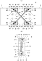
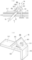
- FIG. 1st Embodiment of the sitting tool which concerns on this invention is shown, (a) is sectional explanatory drawing of a use condition, (b) is a perspective view. It is a perspective explanatory view of the junction structure using the sitting tool shown in FIG. The joining structure using the sitting tool shown in FIG. 1 is shown, (a) is front view explanatory drawing, (b) is side view explanatory drawing.
- the 2nd Embodiment of the sitting tool which concerns on this invention is shown, (a) is sectional explanatory drawing of a use condition, (b) is a perspective view.
- 3rd Embodiment of the sitting tool which concerns on this invention is shown, (a) is sectional explanatory drawing of a use condition, (b) is a perspective view.
- the 4th Embodiment of the sitting tool which concerns on this invention is shown, (a) is sectional explanatory drawing of a use condition, (b) is a perspective view. It is sectional explanatory drawing of the use condition which shows 5th thru
- FIGS. 8 to 10 show a sitting tool used together with the sitting tool of the present invention in the joint structure of FIGS. 8 to 10, wherein FIG. It is sectional explanatory drawing of the use condition which shows the other example of the sitting tool used with the sitting tool of this invention. It is explanatory drawing at the time of using a general washer in the joining structure which clamps and fixes and joins the junction part of a wooden member with the connecting bolt which cross
- the sitting tool 9 is made of metal having sufficient strength, and a contact plate 910 that is a rectangular second contact member, and a contact member that is a first contact member that is formed at a right angle at one end of the contact plate 910. Plate 911.
- a seat plate 912 and a support plate 913 that are formed in a mountain shape and at a right angle in the middle portion are fixed to the surface of the contact plate 910 where the contact plate 911 is provided.
- a triangular cylindrical seat member 90 is integrally formed with the contact plate 910 by a part of the contact plate 910, which is the second contact member, the seat plate 912, and the support plate 913.
- the seat plate 912 is set at an angle of 45 ° with respect to the contact plate 910.
- a circular through-hole 914 is formed in the center of the seat plate 912, and a through-hole 915 is formed in an oblique direction parallel to the support plate 913 near the support plate 913 of the contact plate 910.
- a sitting tool hole 20 (the sitting tool hole 10 in the beam member 1; see FIG.
- the beam member 1 has a flat bottom surface 106 and a flat inner surface 107 (see FIG. 2).
- the sitting tool 9 brings the contact plate 910 into contact with the bottom surface 206 (the bottom surface 106 in the beam member 1) of the sitting tool hole 20 (the sitting tool hole 10 in the beam member 1) formed in the beam member 2. Is used by being brought into contact with the inner side surface 207 (the inner side surface 107 in the beam member 1).
- the connecting bolt 3a passed through the through hole 27 passes through the through holes 915 and 914 of each seating tool 9 from the hole opening 270, and screws the nut 32 into the male screw portion 30 protruding from the seat plate 912.
- the nut 32 is fastened and fixed using the plate 912 as a seat. If necessary, as shown in FIG. 1A, a lid 916 can be placed over the sitting tool hole 20.
- each member such as each connecting bolt is indicated by a solid line so that the drawings can be easily seen and the joining structure can be easily understood.
- the joint structure J is a joint structure in which the beam member 1 and the beam member 2 are joined in the horizontal direction.
- the joint structure J has a beam member 1 and a beam member 2 that are slightly flat and rectangular.
- the joint side of the beam member 1 and the beam member 2 is individually the same structure, and has a symmetrical structure in a state where the joint surfaces 100 and 200 that are the ends of the beam members are in contact with each other.
- the joint surfaces 100 and 200 are formed by rectangular cut surfaces orthogonal to the longitudinal direction (wood fiber direction) of the beam member 1 and the beam member 2.
- sitting tool holes 10 and 20 are formed at positions slightly separated from the joint surfaces 100 and 200 on one surface (upper surface in FIGS. 2 and 3) 11 and 21.
- the sitting hole 10, 20 is a hole having a rectangular parallelepiped space (or a hole formed by providing a rectangular parallelepiped space), and is perpendicular to the bottom surface 106, 206, which is a surface in the wood fiber direction, and the wood fiber direction. It has a structure having inner side surfaces 107 and 207, which are surfaces, an outer side surface, and both side surfaces (both are omitted from the reference numerals).
- the beam member 1 and the beam member 2 are provided with sitting tool holes 15 and 25 at positions slightly away from the joint surfaces 100 and 200 on the other surfaces (lower surfaces in FIGS. 2 and 3) 14 and 24. Yes.
- the sitting tool holes 15 and 25 are the same in structure as the sitting tool holes 10 and 20 except for the orientation. For this reason, in FIG. 2, FIG. 3, in each part of the sitting tool holes 15 and 25, the same code
- the positions of the sitting tool holes 15 and 25 are slightly shifted from the sitting tool holes 10 and 20 in the thickness direction of the beam member 1 and the beam member 2 (left and right direction in FIG. 3B).
- the sitting tool holes 10 and 25 are formed closer to the front (left side in FIG. 3B) 18 and 28 of the beam member 1 and the beam member 2, and the sitting tool holes 15 and 20 are formed on the beam member 1 and the beam member.
- the back surface of the member 2 (right side in FIG. 3B) 19 and 29 is formed (see FIG. 2).
- the beam member 1 is formed with a through hole 17 inclined at 45 ° with respect to the longitudinal direction of the beam member 1 between the bottom surface 106 of the sitting tool hole 10 and the joint surface 100. Between the seat surface 102 and the joint surface 100, a through hole 17 a inclined at 45 ° (inclined opposite to the through hole 17) with respect to the longitudinal direction of the beam member 1 is formed.
- the holes 171 and 173 on the joint surface 100 side connected to the holes 170 and 172 on the bottom surface 106 side of the through holes 17 and 17 a are arranged side by side so as to be substantially in contact with each other in the thickness direction of the beam member 1.
- a through hole 27 inclined at 45 ° with respect to the longitudinal direction of the beam member 2 is formed between the bottom surface 206 of the sitting tool hole 20 and the joint surface 200. Between the bottom face 206 and the joint surface 200, a through hole 27a inclined at 45 ° with respect to the longitudinal direction of the beam member 2 (inclined opposite to the through hole 27) is formed.
- the hole ports 271 and 273 on the joint surface 200 side connected to the hole ports 270 and 272 on the bottom surface 206 side of the through holes 27 and 27 a are arranged side by side so as to be substantially in contact with each other in the thickness direction of the beam member 2.
- the beam member 1 and the beam member 2 are in contact with the joint surfaces 100 and 200, the hole ports 171 and 173 of the joint surface 100 are combined with the hole ports 271 and 273 of the joint surface 200, and the through hole 17.
- the through hole 27a are connected to form a linear hole, and the through hole 17a and the through hole 27 are connected to form a linear hole.
- the through-hole 17 and the through-hole 17a, and the through-hole 27 and the through-hole 27a are arrange
- the sitting tool 9 abuts the abutting plate 910 against the inner side surfaces 107 and 207 by bringing the abutting plate 910 into contact with the bottom surfaces 106 and 206 of the sitting tool holes 10, 15, 20 and 25 formed in the beam member 2. It is fitted in contact.
- the connecting bolt 3 is passed through the through hole 17 and the through hole 27a connected as described above, and the connecting bolt 3a is passed through the through hole 17a and the through hole 27.
- the connecting bolts 3 and 3a have male screw portions 30 on both ends.
- the lengths of the connecting bolts 3 and 3a are set so that the male screw portions 30 at both ends receive the seat holes 10 and 20 when the through bolts 17 and 27a and the through holes 17a and the through holes 27 pass through the connecting bolts 3 and 3a. It is formed to have a length slightly protruding from the through hole 914 of the seat plate 912 of the tool 9. And the nut 32 is screwed and fastened to each male screw part 30 of the both ends of the connecting bolts 3 and 3a. As a result, the beam member 1 and the beam member 2 are attracted to each other, the joining surfaces 100 and 200 are in close contact, and the beam member 1 and the beam member 2 are joined.
- the joining structure J In the joint structure J, a pulling force acting on the crossed diagonally connected connecting bolts 3 and 3a is generated by applying a pulling direction load acting on the beam member 1 and the beam member 2 and a shearing direction load acting on the joint surfaces 100 and 200. Can be shared and supported by the power of. Therefore, the joining structure J is a simple structure, but when a shearing load is applied to the joining surfaces 100 and 200 in any of the vertical directions, the joining structure J can be received with a component force in the direction opposite to the force.
- the beam members 1 and 2 to be joined have a weak load resistance against the load and are easily deformed, that is, the surface in the wood fiber direction, that is, the sitting tool hole. 10, 15, 20, 25, and the bottom surfaces 106, 206 and the surface perpendicular to the direction of the wood fiber, which is strong and difficult to deform, that is, the inner surfaces 107, 207 of the sitting tool holes 10, 15, 20, 25 It has become.
- the tightening force by the nut 32 acting on the sitting tool 9 becomes a component force with respect to the bottom surfaces 106 and 206 and the inner side surfaces 107 and 207, and the surface receiving the abutment plates 911 and 910 of the sitting tool 9, that is, the direction of wood fiber having a strong proof stress.
- the bottom surfaces 106 and 206 that are weakly proof in the wood fiber direction are not likely to be greatly deformed.
- the component force of the tensile force acting on the connecting bolts 3 and 3a (the component force different from the component force acting on the bottom surfaces 106 and 206 in the wood fiber direction) is orthogonal to the wood fiber direction having a higher proof strength against the load. It acts on the inner side surfaces 107 and 207. Thereby, the position shift of the sitting tool 9 in the wood fiber direction due to the above component force hardly occurs, and the sitting tool 9 can be stabilized when the connecting bolts 3 and 3a are fixed.
- the load such as the tightening force by the nut 32 acting on the bottom surfaces 106 and 206 and the inner surfaces 107 and 207 of the seat holes 10, 15, 20, and 25 by the seat 9 or the beam member 1 after construction.
- the load such as the tightening force by the nut 32 acting on the bottom surfaces 106 and 206 and the inner surfaces 107 and 207 of the seat holes 10, 15, 20, and 25 by the seat 9 or the beam member 1 after construction.
- the sitting tool 9a is made of metal having sufficient strength, and a contact plate 905 that is a rectangular second contact member, and a contact member that is a first contact member formed at a right angle at one end of the contact plate 905.
- a plate 906 and a seat plate 907 hung on the inner surface of the contact plate 905 and the contact plate 906 at an angle of 45 °.
- a circular through hole 908 is formed at the center of the seat plate 907, and a through hole 909 is formed at a corner portion formed by the contact plate 905 and the contact plate 906.
- a triangular cylindrical seat member 90 a is integrally formed with the contact plates 905 and 906 by a part of the contact plate 905, a part of the contact plate 906 and the seat plate 907.
- the sitting tool 9a is used in a sitting tool hole 20a formed in the beam member 2a as shown in FIG.
- a sitting tool hole (not shown) is provided on the opposite side, and the sitting tool 9a is housed in the sitting tool hole.
- the sitting tool hole 20a is a hole having a rectangular parallelepiped space (or a hole formed by providing a rectangular parallelepiped space), and has a flat bottom face 206a and a flat inner side face 207a, an outer face, and both side faces ( All have a symbol omitted).
- the sitting tool 9a is fitted with the contact plate 905 in contact with the bottom surface 206a of the sitting tool hole 20a and the contact plate 906 in contact with the inner surface 207a. Further, the connecting bolt 3 a passed through the through hole 27 passes through the through holes 909 and 908 of each seating tool 9 a from the hole opening 270 a, and screws the nut 32 into the male screw portion 30 protruding from the seat plate 907. The nut 32 is fastened and fixed using the seat plate 907 as a seat.
- action of the sitting tool 9a since it is substantially the same as the said sitting tool 9, description is abbreviate
- the sitting tool 9b is different from the sitting tools 9 and 9a in that it is fixed to the surface of the column member or the beam member 2b, and no sitting tool hole is formed in the beam member or the like. Therefore, the hole 270b of each through hole (the through hole 27 is shown in FIG. 6A) is opened on the surface of the beam member 2b.
- the sitting tool 9b is made of metal and has a rectangular abutting plate 917 as a second abutting member and a vertical plate 918 as a first abutting member formed at right angles to one end of the abutting plate 917. ing.
- a seat plate 919 and a support plate 920 that are formed in a mountain shape and at a right angle in the middle part are fixed to the surface (upper surface in FIG. 5) opposite to the side on which the vertical plate 918 is provided. Yes.
- the seat plate 919 is set at an angle of 45 ° with respect to the contact plate 917.
- a circular through hole 921 is formed in the center of the seat plate 919, and a through hole 922 is formed in the oblique direction parallel to the support plate 920 near the vertical plate 918 of the contact plate 917.
- a triangular cylindrical seat member 90 b is integrally formed with the contact plate 917 by a part of the contact plate 917, the seat plate 919, and the support plate 920.
- the sitting tool 9b has a vertical plate 918 attached to the surface of the beam member 2b so that the through hole 922 is aligned with the hole 270b of each through hole (the through hole 27 is shown in FIG. 6A) of the column member or the beam member 2b. Then, the contact plate 917 is fixed in close contact with the surface of the beam member or the like.
- the connecting bolt 3a passed through the through hole 27 passes through the through holes 922 and 921 from the hole opening 270b, screws the nut 32 into the male screw portion 30 protruding from the seat plate 919, and attaches the seat plate 919 to the seat portion.
- the nut 32 is fastened and fixed.
- the seating tool 9b can disperse the tightening force by the nut 32 as in the case of the seating tools 9 and 9a, and can prevent deformation of the portion to which the seating tool 9b is fixed by the contact plate 917 of the seating tool 9b. .
- the sitting tool 9b has a structure that is directly fixed to the surface of a wooden member such as a beam member as described above, unlike the sitting tools 9 and 9a, a housing part such as a sitting tool hole is provided on the wooden member side. Therefore, there is an advantage that the joining structure can be further simplified.
- the sitting tool 9c is a specification attached to the surface of a column member or the beam member 2c similarly to the said sitting tool 9b, and a sitting tool hole is not formed in a beam member etc. Therefore, the hole 270c of each through hole (the through hole 27 is shown in FIG. 6A) is open to the surface of the beam member 2c.
- the sitting tool 9c is made of metal and has a rectangular contact plate 923 as a second contact member and vertical plates 924 and 925 as first contact members formed at right angles to both ends of the contact plate 923. is doing.
- a seat formed in a mountain shape and at a right angle in the middle, slightly closer to the vertical plate 924 than the center of the surface opposite to the side on which the vertical plates 924 and 925 are provided (the upper surface in FIG. 6).
- a plate 926 and a support plate 927 are fixed.
- the seat plate 926 is set at an angle of 45 ° with respect to the contact plate 923.
- a circular through hole 928 is formed at the center of the seat plate 926, and a through hole 929 is formed below the seat plate 926 and the support plate 927 of the contact plate 923 in an oblique direction parallel to the support plate 927.
- a triangular cylindrical seat member 90c is formed integrally with the contact plate 923 by a part of the contact plate 923, the seat plate 926, and the support plate 927.
- the sitting tool 9c is configured such that the vertical plates 924 and 925 are arranged as beam members so that the through holes 929 are aligned with the hole openings 270c of the respective through holes (the through hole 27 is shown in FIG. 6A) such as a column member and a beam member.
- the contact plate 923 is fixed to the surface of the beam member 2c in close contact with the surface of the beam member 2c.
- the connecting bolt 3a passed through the through hole 27 passes through the through holes 929 and 928 through the hole 270c, and the nut 32 is screwed into the male screw portion 30 protruding from the seat plate 926, and the seat plate 926 is used as the seat portion.
- the nut 32 is fastened and fixed.
- the operation of the sitting tool 9c is substantially the same as that of the sitting tool 9b described above except that the fixing force to the wooden member becomes stronger by the amount of two vertical plates driven into the wooden member such as a beam member. Since there is, description is abbreviate
- FIG. 7 5th-8th Embodiment of the sitting tool based on this invention is described.
- FIG. 7 in order to briefly explain the structure and mounting structure of each seat 9d to 9g, illustration of through holes and hole openings is omitted, and connection bolts are simply represented by straight lines and symbols are omitted. is doing.
- symbol of wooden members, such as a beam member is also abbreviate
- Each of the sitting tools 9d to 9g shown in FIG. 7 has a through hole through which the connecting bolt of the sitting tools 9 to 9c is passed or a screwed tube to be screwed at one place, whereas the through holes through which the connecting bolt is passed. Is different in that it can be passed through two connecting bolts.
- portions that are substantially equivalent to the sitting tools 9 to 9c are denoted by the same reference numerals.
- the seat 9d of the fifth embodiment shown in FIG. 7A has a structure in which the seat 9 is roughly combined (each seat plate 912 is gathered in one seat member 90d). .
- the through holes 915 and 915a formed in the plate 910 are shifted in the depth direction in the drawing in the same manner as the through holes 914 formed in each seat plate 912.
- the seat 9e according to the sixth embodiment shown in FIG. 7 (b) has a structure in which the seat 9 is roughly combined (the seat member 90e having the seat plate 12 is provided at two required intervals). It is in).
- the through holes 915b and 915c formed in the abutting plate 910 are shifted in the depth direction in the drawing similarly to the through holes 914 formed in each seat plate 912.
- the sitting tool 9f of the seventh embodiment shown in FIG. 7C has a structure in which seat plates 926 are formed in two places on the seat member 90f of the sitting tool 9c.
- the through holes 915d and 915e formed in the contact plate 923 are shifted in the depth direction in the drawing similarly to the through holes 928 formed in each seat plate 926.
- the seat 9g of the eighth embodiment shown in FIG. 7 (d) has a structure in which the seat member is formed in two places with a required interval in the seat 9c, that is, the seat member 90g is formed in two places. It has a structure.
- the through holes 915f and 915g formed in the contact plate 923 are shifted in the depth direction in the drawing in the same manner as the through holes 928 formed in each seat plate 926.
- the operation of the seats 9d to 9g is that the two connecting bolts can be fixed with one seating tool in different pulling directions because the through holes for passing the connecting bolts are formed in two places. Except for the above, the operation of the seats 9 and 9c, which are the basis of the structure, is almost the same, and the description thereof is omitted.
- FIG. 8 a use state when the sitting tool is used for the joint structure of the column member 4 and the beam members 1 and 2 will be described.
- crossed diagonal connecting bolts 3 b and 3 c are used for joining the column member 4 and the beam member 1
- crossed obliquely connected bolts are used for joining the column member 4 and the beam member 2.
- 3d and 3e are used.
- a sitting tool 9c that is paired at both ends of each connecting bolt and a sitting tool 9h described later are provided. in use.
- the sitting tool 9h has a structure in which the connecting bolts 3b, 3c, 3d, and 3e are rotated and screwed into the female screw portion 934 to be fixed, the same sitting tool 9h is not used on the pair side.
- the work can be simplified by fixing the one end side of the connecting bolts 3b, 3c, 3d, and 3e by screwing into the female screw portion 934.
- connecting bolts 3h and 3i arranged and fixed in the crossing direction are used for joining the columns of the take-out beam 6 and the beams.
- the sitting tool 9c and the sitting tool 9h that are paired at both ends of each connecting bolt are used.
- work by fixing the one end side of connecting bolt 3h, 3i to the internal thread part 934 of the seat 9h is the same as that of the joining structure shown in FIG.
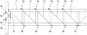
- connecting bolts 3k and 3m are used for joining the columns of the truss beam structure 7 and the truss beams, and connecting bolts 3j arranged and fixed for reinforcement in the crossing direction of the truss beams are used.
- a sitting tool used for fixing the connecting bolts 3k and 3m a sitting tool 9c and a sitting tool 9i which are paired at both ends of each connecting bolt are used, and a sitting tool used for fixing each connecting bolt 3j.
- a pair of sitting tool 9c, sitting tool 9h, and sitting tool 9i are used at both ends of each connecting bolt.
- the connection bolts 3k, 3m, and 3j are fixed on one end side by screwing the seating tool 9h and the seating tool 9i into the female threaded portion 934. It is the same as the joint structure shown in FIG.
- the sitting tool used with the sitting tool based on this invention is demonstrated.
- the sitting tool 9h is made of metal and has a rectangular contact plate 930 and vertical plates 931 and 932 formed at right angles to both ends of the contact plate 930.
- a female threaded portion 934 through which a threaded tube 933 passes the center is located slightly closer to the vertical plate 931 than the center of the surface (the lower surface in FIG. 11) on the same side as the side on which the vertical plates 931 and 932 of the plate 930 are provided. Is fixed through the contact plate 930. Further, the direction of the center line of the threaded tube 933 is set at an angle of 45 ° with respect to the contact plate 930.
- the sitting tool 9h has a female thread portion of the threaded tube 933 in the hole 270h (formed on the inclined surface) of each through hole (the through hole 27 is shown in FIG. 11A) of the column member or the beam member 2h.
- Vertical plates 931 and 932 are driven into the surface of the beam member so as to match 934, and the contact plate 930 is closely attached to the surface of the beam member 2h and fixed.
- tube 933 fits is formed in the surface previously.
- the connecting bolt 3 a passed through the through hole 27 is fixed by screwing the male screw portion 30 into the female screw portion 934.
- the seat 9i shown in FIG. 12 (a) is roughly formed with the threaded tube 933 of the seat 9h at two locations with a predetermined interval so that the female screw portion 934 faces each other although the angle of the axis is different. Has a structured. Each threaded tube 933 is shifted in position in the depth direction of the drawing.
- the sitting tool 9j shown in FIG. 12 (b) has a structure in which the screwing tube of the sitting tool 9h is formed at two positions with a predetermined interval, that is, a screwing pipe 933a is formed at two positions.
- the female screw portion 934a has a structure formed so as to face in opposite directions to each other although the angle of the axis is different. Each threaded tube 933a is shifted in position in the depth direction in the figure.
Landscapes
- Engineering & Computer Science (AREA)
- Architecture (AREA)
- Physics & Mathematics (AREA)
- Electromagnetism (AREA)
- Civil Engineering (AREA)
- Structural Engineering (AREA)
- Joining Of Building Structures In Genera (AREA)
Abstract
本発明の座具は、木質部材の接合部を、斜めに交差させた連結ボルトで締め付け固定して接合する接合構造において使用され、木質部材の荷重に対する耐力が強く変形しにくい面に当てる当板と、荷重に対する耐力が弱く変形しやすい面に当てる当板と、当板の一部と一体的に三角筒状に形成され、三角筒状部を構成する当板と座板に連結ボルトを通す通孔が形成されており、木質の面に対し作用する荷重による当該面の変形を抑えて、木軸構造体等の施工後の緩みや変形を防止できる。
Description
本発明は、木質部材の接合構造に使用する座具に関するものである。更に詳しくは、柱部材又は梁部材等の木質部材の接合部を斜めに交差させた連結ボルトで締め付け固定して接合する接合構造において、連結ボルトの固定に使用する座具であって、座具が密着する木部の、締付ナット等による締付力、或いは施工後の荷重による変形を抑えて、木軸構造体等の施工後の構造体の緩みや変形を防止できるものに関する。
例えば木軸構造体は、構成部材である柱部材や梁部材等の木質部材を連結ボルトや連結金具等の連結具を介し接合して構築されている。このような木軸構造体は、木質の橋や屋根等の各種構造物の骨組としても広く応用されている。
軸組構造体の各木質部材の接合には、一般に接合具が外部から見えないか、又は見えにくいようにした接合構造が主に採用されている。このような接合構造には、図13に示すように、接合部において連結ボルト82、83を隣接して交差させることにより、構造が簡易でありながら木質部材8、8aの接合面88、89における引っ張り方向の荷重だけでなく、同時にスラスト方向の荷重に対しても十分な耐力を有する構造としたものがある。
このように連結ボルト82、83を隣接して交差させる接合構造では、各連結ボルト82、83は、木質部材8、8aの軸方向に対して、例えば45°等の所要の角度をもって貫通孔85、86a及び貫通孔85a、86に通してナット84で締め付け固定されている。そして、連結ボルト82、83をナット84で締め付けるために、木質部材8、8aに穴80を設けて座面81を傾斜させて形成し、座面81に一般的な座金87を密着させて使用している。
図13に示している接合構造の穴80は、平面視で長方形状であり、断面形状がV字形である。この例では、穴80において木質部材8、8aの接合面88、89に近い側の座面81(座金87が密着する面)の角度は、木質部材8、8aの上面に対し45°に設定されている。
しかしながら、上記のように一般的な座金を使用し、交差した斜張りの連結ボルトで固定する接合構造においては、次のような課題があった。
すなわち、従来から知られているように、木材は、木繊維方向と、木繊維方向と直角方向とで荷重に対する耐力に差があり、その差は、1:0.34~1:0.4程度とされている。
すなわち、従来から知られているように、木材は、木繊維方向と、木繊維方向と直角方向とで荷重に対する耐力に差があり、その差は、1:0.34~1:0.4程度とされている。
このため、図13に示すように、交差した斜張りの連結ボルトで斜め方向に引っ張り力を作用させると、一般のボルトナット用の座金を使用した場合では、座面の耐力が方向によってアンバランスであるために、座金は座面の耐力の弱い方向(木繊維方向と直角方向)に、より大きく木部を変形させ、座金の位置がずれたり、木部にめり込んだりして、木軸構造体そのものに大きな変形を生じるおそれがあった。
すなわち、上記のような交差した斜張りの連結ボルトを木部に対し十分に有効な耐力をもって固定するには、座具の形状を、木質部材の座具が密着する座面の木繊維方向と木繊維方向と直角方向で耐力が異なることを勘案して、座具の支持力が最も有効、且つ効果的に働くような形状とする必要があり、本発明はこれを実現するものである。
(本発明の目的)
本発明の目的は、柱部材又は梁部材等の木質部材の接合部を斜めに交差させた連結ボルトで締め付け固定して接合する接合構造において、連結ボルトの固定に使用する座具であって、座具により木質の面に対し作用する締付力等の荷重、或いは施工後の木質部材の重み等の荷重等による木質の面の変形を抑えて、木軸構造体等の構造体の施工後の緩みや変形を防止できる座具を提供することである。
本発明の目的は、柱部材又は梁部材等の木質部材の接合部を斜めに交差させた連結ボルトで締め付け固定して接合する接合構造において、連結ボルトの固定に使用する座具であって、座具により木質の面に対し作用する締付力等の荷重、或いは施工後の木質部材の重み等の荷重等による木質の面の変形を抑えて、木軸構造体等の構造体の施工後の緩みや変形を防止できる座具を提供することである。
上記課題を解決するために本発明が講じた手段は次のとおりである。
(1)本発明は、
木質部材の接合部を斜めに交差させた連結ボルトで締め付け固定して接合する接合構造において、連結ボルトの固定に使用する座具であって、接合する木質部材において荷重に対する耐力が強く変形しにくい木繊維方向と直交する面に当てる板状の第1の当て部材と、接合する木質部材において荷重に対する耐力が前記木繊維方向と直交する面より弱く変形しやすい木繊維方向の面に当てる板状の第2の当て部材と、前記第1の当て部材と前記第2の当て部材の一方又は双方の一部と一体的に三角筒状に形成され、該三角筒状部を構成する少なくとも二枚の板部に連結ボルトを通す通孔がそれぞれ形成されており、該通孔が形成された板部のうち前記第1の当て部材又は前記第2の当て部材でない板部が座板となっている座部材とを備える座具である。
(2)本発明は、
木質部材の接合部を斜めに交差させた連結ボルトで締め付け固定して接合する接合構造において、連結ボルトの固定に使用する座具であって、接合する木質部材において、木繊維方向の面に形成され、直方体形状の空間を有する座具穴の平面状の内側面のうち、荷重に対する耐力が強く変形しにくい木繊維方向と直交する内側面に当てる板状の第1の当て部材と、接合する木質部材において荷重に対する耐力が前記木繊維方向と直交する前記座具穴の内側面より弱く変形しやすい木繊維方向の底面に当てる板状の第2の当て部材と、前記第1の当て部材と前記第2の当て部材の一方又は双方の一部と一体的に三角筒状に形成され、該三角筒状部を構成する少なくとも二枚の板部に連結ボルトを通す通孔がそれぞれ形成されており、該通孔が形成された板部のうち前記第1の当て部材又は前記第2の当て部材でない板部が座板となっている座部材とを備える座具である。
木質部材の接合部を斜めに交差させた連結ボルトで締め付け固定して接合する接合構造において、連結ボルトの固定に使用する座具であって、接合する木質部材において、木繊維方向の面に形成され、直方体形状の空間を有する座具穴の平面状の内側面のうち、荷重に対する耐力が強く変形しにくい木繊維方向と直交する内側面に当てる板状の第1の当て部材と、接合する木質部材において荷重に対する耐力が前記木繊維方向と直交する前記座具穴の内側面より弱く変形しやすい木繊維方向の底面に当てる板状の第2の当て部材と、前記第1の当て部材と前記第2の当て部材の一方又は双方の一部と一体的に三角筒状に形成され、該三角筒状部を構成する少なくとも二枚の板部に連結ボルトを通す通孔がそれぞれ形成されており、該通孔が形成された板部のうち前記第1の当て部材又は前記第2の当て部材でない板部が座板となっている座部材とを備える座具である。
(作用)
本発明に係る座具の作用を説明する。
座具は、木質部材の接合部を斜めに交差させた連結ボルトで締め付け固定して接合する接合構造において、連結ボルトの固定に使用する際に、板状の第1の当て部材を、接合する木質部材において荷重に対する耐力が強く変形しにくい木繊維方向と直交する面に当て、板状の第2の当て部材を、接合する木質部材において荷重に対する耐力が木繊維方向と直交する面より弱く変形しやすい木繊維方向の面に当てるようになっている。
本発明に係る座具の作用を説明する。
座具は、木質部材の接合部を斜めに交差させた連結ボルトで締め付け固定して接合する接合構造において、連結ボルトの固定に使用する際に、板状の第1の当て部材を、接合する木質部材において荷重に対する耐力が強く変形しにくい木繊維方向と直交する面に当て、板状の第2の当て部材を、接合する木質部材において荷重に対する耐力が木繊維方向と直交する面より弱く変形しやすい木繊維方向の面に当てるようになっている。
そして、座部材は三角筒状に形成されているので、座具は全体として極めて高い剛性を有し、しかも筒状体は中抜き構造であるため、中実なものと比較して軽量化できる。更に、座具は、例えば当て部材にV字型の板を溶接する等して製作が容易にでき、プレス加工とは相違して肉厚にすることも簡単にできるので、木軸構造に使用する座具として、大荷重に絶え得る充分な強度で製作することができる。
また、三角筒状部の少なくとも二枚の板部に通す通孔がそれぞれ形成されていることにより、通孔と通孔は間隔が開いており、連結ボルトを二点で支えることができる(両端側で合計四点)ので、連結ボルトの軸が振れにくく、より精度が高く強固な施工が可能になる。
通孔が形成され連結ボルトが通される座板は、当て部材に対し傾斜して形成されているので、当て部材により木質の面に対し作用する荷重は、交差した斜張りの連結ボルトに作用する引っ張り力の分力となって小さくなり、しかもその荷重は面と面の当接により支えられるので、荷重が均等に分散し、座具の当て部材を受ける木質の面、すなわち耐力が強い木繊維方向と直交する面はもとより、耐力が弱い木繊維方向の面にも大きな変形は生じにくい。
なお、連結ボルトに作用する引っ張り力の分力が、荷重に対し耐力がより強い木繊維方向と直交する面に作用するので、上記分力による木繊維方向の座具の位置のずれが起こりにくく、連結ボルトの固定時において座具を安定させることができる。
なお、連結ボルトに作用する引っ張り力の分力が、荷重に対し耐力がより強い木繊維方向と直交する面に作用するので、上記分力による木繊維方向の座具の位置のずれが起こりにくく、連結ボルトの固定時において座具を安定させることができる。
このように、座具により木繊維方向とは直交する面及び木繊維方向の面に対し作用するナットの締付力等の荷重、或いは施工後の木質部材の重み等の荷重等による木質の面の変形を抑えることができるので、木軸構造体等の施工後の構造体の緩みや変形を防止することができる。
本発明は、木質部材の接合部を斜めに交差させた連結ボルトで締め付け固定して接合する接合構造において、連結ボルトの固定に使用する際に、第1の当て部材を荷重に対する耐力が強く変形しにくい木繊維方向と直交する面に当て、第2の当て部材を荷重に対する耐力が弱く変形しやすい木繊維方向の面に当てるようになっている。そして、通孔が形成され連結ボルトが通される座板は、当て部材に対し傾斜して形成されているので、当て部材により木繊維方向の面に対し作用する荷重は、交差した斜張りの連結ボルトに作用する引っ張り力の分力となって小さくなり、しかもその荷重は面と面の当接により支えられるので荷重が均等に分散し、座具の当て部材を受ける木繊維方向の面及び木繊維方向と直交する面に大きな変形は生じにくい。
このように、座具により木繊維方向の面及び木繊維方向と直交する面に対し作用する締付ナットの締付力等の荷重、或いは施工後の木質部材の重み等の荷重等による木質の面の変形を抑えることができるので、木軸構造体等の構造体の施工後の緩みや変形を防止することができる。
このように、座具により木繊維方向の面及び木繊維方向と直交する面に対し作用する締付ナットの締付力等の荷重、或いは施工後の木質部材の重み等の荷重等による木質の面の変形を抑えることができるので、木軸構造体等の構造体の施工後の緩みや変形を防止することができる。
本発明を図面に示した実施の形態に基づき詳細に説明する。
まず、図1を参照する。
座具9は、十分な強度を有する金属製であり、長方形状の第2の当て部材である当板910と、当板910の一端に直角に形成された、第1の当て部材である当板911とを有している。当板910の当板911が設けられている側の面には、中間部で山型に且つ直角に形成された座板912と支持板913が固着されている。
まず、図1を参照する。
座具9は、十分な強度を有する金属製であり、長方形状の第2の当て部材である当板910と、当板910の一端に直角に形成された、第1の当て部材である当板911とを有している。当板910の当板911が設けられている側の面には、中間部で山型に且つ直角に形成された座板912と支持板913が固着されている。
これにより、第2の当て部材である当板910の一部と座板912と支持板913により、三角筒状の座部材90が当板910と一体的に形成されている。座板912は、当板910に対し45°の角度に設定されている。また、座板912の中央には円形の通孔914が形成されており、当板910の支持板913寄りには、支持板913と平行な斜め方向に通孔915が形成されている。梁部材2に形成された座具穴20(梁部材1では座具穴10:図2参照)は、直方体形状の空間を有する穴で、平面状の底面206及び同じく平面状の内側面207(梁部材1では平面状の底面106及び同じく平面状の内側面107:図2参照)を有している。
座具9は、当板910を梁部材2に形成されている座具穴20(梁部材1では座具穴10)の底面206(梁部材1では底面106)に当接させ、当板911を内側面207(梁部材1では内側面107)に当接させて収められて使用される。貫通孔27に通された連結ボルト3aは、孔口270から各座具9の各通孔915、914を貫通し、座板912から突出した雄ネジ部30にナット32を螺合し、座板912を座部としてナット32を締め付けて固定されている。なお、必要であれば、図1(a)に示すように、座具穴20に蓋916を被せることもできる。
ここで、図2及び図3を参照して、上記座具9を使用した木質部材の接合構造を説明する。
なお、図2及び図3においては、図面を見やすく、接合構造をわかりやすくために各連結ボルト等の各部材を実線で表している。
なお、図2及び図3においては、図面を見やすく、接合構造をわかりやすくために各連結ボルト等の各部材を実線で表している。
接合構造Jは、梁部材1と梁部材2とを水平方向に接ぎ合わせる接合構造である。
接合構造Jは、やや扁平な四角柱状の梁部材1と梁部材2を有している。梁部材1と梁部材2の接合側は、個々では互いに同一構造であり、木口である接合面100、200を当接させた状態で対称構造を有している。接合面100、200は、梁部材1と梁部材2の長手方向(木繊維方向)と直交する長方形状の切断面で形成されている。
接合構造Jは、やや扁平な四角柱状の梁部材1と梁部材2を有している。梁部材1と梁部材2の接合側は、個々では互いに同一構造であり、木口である接合面100、200を当接させた状態で対称構造を有している。接合面100、200は、梁部材1と梁部材2の長手方向(木繊維方向)と直交する長方形状の切断面で形成されている。
梁部材1と梁部材2には、一方の面(図2、図3では上面)11、21において接合面100、200からやや離れた位置に座具穴10、20が形成されている。座具穴10、20は、直方体形状の空間を有する穴(又は直方体形状の空間を設けることで形成された穴)で、木繊維方向の面である底面106、206、木繊維方向と直交する面である内側面107、207、外側面及び両側側面(何れも符号省略)を有する構造である。
また、梁部材1と梁部材2には、他方の面(図2、図3では下面)14、24において、接合面100、200からやや離れた位置に座具穴15、25が形成されている。座具穴15、25は、上記座具穴10、20とは向きが異なるだけで、構造は同一である。このため、図2、図3では、座具穴15、25の各部において、座具穴10、20と同等箇所に同じ符号を付し、構造の説明は省略する。
座具穴15、25の位置は、上記座具穴10、20とは、梁部材1と梁部材2の厚み方向(図3(b)で左右方向)に、ややずらしてある。なお、上記座具穴10、25は、梁部材1と梁部材2の正面(図3(b)で左側)18、28寄りに形成され、座具穴15、20は、梁部材1と梁部材2の背面(図3(b)で右側)19、29寄りに形成されている(図2参照)。
更に、梁部材1には、座具穴10の底面106と接合面100の間に、梁部材1の長手方向に対し45°で傾斜した貫通孔17が形成されており、上記座具穴15の座面102と接合面100の間に、梁部材1の長手方向に対し45°で傾斜(上記貫通孔17とは反対に傾斜)した貫通孔17aが形成されている。貫通孔17、17aの底面106側の孔口170、172とつながる接合面100側の孔口171、173は、梁部材1の厚み方向にほぼ接するように並設されている。
梁部材2には、上記座具穴20の底面206と接合面200の間に、梁部材2の長手方向に対し45°で傾斜した貫通孔27が形成されており、上記座具穴25の底面206と接合面200の間に、梁部材2の長手方向に対し45°で傾斜(上記貫通孔27とは反対に傾斜)した貫通孔27aが形成されている。貫通孔27、27aの底面206側の孔口270、272とつながる接合面200側の孔口271、273は、梁部材2の厚み方向にほぼ接するように並設されている。
そして、梁部材1と梁部材2は、接合面100、200を当接させた状態で、接合面100の孔口171、173は、接合面200の孔口271、273と合わさり、貫通孔17と貫通孔27aがつながって直線状の孔となると共に、貫通孔17aと貫通孔27がつながって直線状の孔となる。また、貫通孔17と貫通孔17a、及び貫通孔27と貫通孔27aは、それぞれ交点でほぼ接するように直交状態に配置されているが、所要距離を隔てた状態に配置してもよいし、交差する角度も適宜設定することができる。
なお、座具9は、当板910を梁部材2に形成されている座具穴10、15、20、25の底面106、206に当接させ、当板911を内側面107、207に当接させて嵌装されている。上記のようにつながった貫通孔17と貫通孔27aには連結ボルト3が通され、貫通孔17aと貫通孔27には連結ボルト3aが通されている。連結ボルト3、3aは、両端側に雄ネジ部30を有している。
連結ボルト3、3aの長さは、貫通孔17と貫通孔27a及び貫通孔17aと貫通孔27に通したときに、両端側の雄ネジ部30が、座具穴10、20に収容した座具9の座板912の通し孔914からやや突出する長さに形成されている。そして、連結ボルト3、3aの両端部の各雄ネジ部30には、ナット32が螺合され、締め込まれている。これにより、梁部材1と梁部材2は互いに引き寄せられ、接合面100、200は強く密着し、梁部材1と梁部材2は接合される。
なお、各連結ボルト3、3aと各貫通孔17、17a、27、27aの間の空隙(符号省略)に起因する接合構造の変形や歪みを防止するため、あるいは接合構造Jの強度を更に高めるために、エポキシ樹脂等の高強度樹脂を連結ボルト3、3a周りの空隙に充填することもできる。
(作用)
接合構造Jは、梁部材1と梁部材2に作用する引き寄せ方向の荷重と、接合面100、200に作用する剪断方向の荷重を、交差した斜張りの連結ボルト3、3aに作用する引っ張り力の分力で分担して支えることができる。したがって、接合構造Jは、簡易な構造でありながら、接合面100、200に上下方向の何れかに剪断方向の荷重が作用したときは、その力と反対方向の分力で受けることができる。
接合構造Jは、梁部材1と梁部材2に作用する引き寄せ方向の荷重と、接合面100、200に作用する剪断方向の荷重を、交差した斜張りの連結ボルト3、3aに作用する引っ張り力の分力で分担して支えることができる。したがって、接合構造Jは、簡易な構造でありながら、接合面100、200に上下方向の何れかに剪断方向の荷重が作用したときは、その力と反対方向の分力で受けることができる。
また、座具9は、上記したように連結ボルト3、3aの固定に使用する際に、接合する梁部材1、2において荷重に対する耐力が弱く変形しやすい木繊維方向の面、すなわち座具穴10、15、20、25の底面106、206及び耐力が強く変形しにくい木繊維方向と直交する面、すなわち座具穴10、15、20、25の内側面107、207に対して当てるようになっている。
そして、座具9に作用するナット32による締め付け力は、底面106、206及び内側面107、207に対する分力となり、座具9の当板911、910を受ける面、すなわち耐力が強い木繊維方向とは直交する面である内側面107、207はもとより、耐力が弱い木繊維方向の面である底面106、206にも大きな変形は生じにくい。
また、連結ボルト3、3aに作用する引っ張り力の分力(木繊維方向の底面106、206に作用する分力とは異なる分力)が、荷重に対し耐力がより強い木繊維方向と直交する内側面107、207に作用する。これにより、上記分力による木繊維方向の座具9の位置のずれが起こりにくく、連結ボルト3、3aの固定時において座具9を安定させることができる。
このように、座具9により座具穴10、15、20、25の底面106、206及び内側面107、207に対し作用するナット32による締付力等の荷重、或いは施工後の梁部材1、2等、木質部材の重みによる荷重等による変形を抑えることができるので、木軸構造体等の施工後の構造体の緩みや変形を防止することができる。
図4を参照し、本発明の第2実施の形態を説明する。
座具9aは、十分な強度を有する金属製であり、長方形状の第2の当て部材である当板905と、当板905の一端に直角に形成された、第1の当て部材である当板906と、当板905と当板906の内側の面に45°の角度で掛けられた座板907を有している。座板907の中央には円形の通孔908が形成されており、当板905と当板906が形成する角部には、通孔909が形成されている。これにより、当板905の一部と当板906の一部及び座板907により、三角筒状の座部材90aが当板905、906と一体的に形成されている。
座具9aは、十分な強度を有する金属製であり、長方形状の第2の当て部材である当板905と、当板905の一端に直角に形成された、第1の当て部材である当板906と、当板905と当板906の内側の面に45°の角度で掛けられた座板907を有している。座板907の中央には円形の通孔908が形成されており、当板905と当板906が形成する角部には、通孔909が形成されている。これにより、当板905の一部と当板906の一部及び座板907により、三角筒状の座部材90aが当板905、906と一体的に形成されている。
座具9aは、図4(a)に示すように梁部材2aに形成されている座具穴20aに収められて使用される。実際の使用では、上記接合構造Jの場合と同様に、対向する側にも座具穴(図示省略)が設けられ、座具穴に座具9aが収められて使用されるが、ここでは説明の便宜上、一箇所の座具穴における使用状態を説明する(後で説明する座具9b、9c、9d、9eも同様)。
座具穴20aは、直方体形状の空間を有する穴(又は直方体形状の空間を設けることで形成された穴)で、平面状の底面206a及び同じく平面状の内側面207a、外側面及び両側面(何れも符号省略)を有している。
座具穴20aは、直方体形状の空間を有する穴(又は直方体形状の空間を設けることで形成された穴)で、平面状の底面206a及び同じく平面状の内側面207a、外側面及び両側面(何れも符号省略)を有している。
座具9aは、当板905を座具穴20aの底面206aに当接させ、当板906を内側面207aに当接させて嵌装されている。また、貫通孔27に通された連結ボルト3aは、孔口270aから各座具9aの各通孔909、908を貫通し、座板907から突出した雄ネジ部30にナット32を螺合し、座板907を座部としてナット32を締め付けて固定されている。
なお、座具9aの作用については、上記座具9と実質的に同様であるので、説明を省略する。
なお、座具9aの作用については、上記座具9と実質的に同様であるので、説明を省略する。
図5を参照し、本発明の第3実施の形態を説明する。
座具9bは、上記座具9、9aとは相違して、柱部材や梁部材2bの表面に固定する仕様であり、梁部材等には座具穴は形成されない。したがって、各貫通孔(図6(a)では貫通孔27を図示)の孔口270bは、梁部材2bの表面に開口している。
座具9bは、上記座具9、9aとは相違して、柱部材や梁部材2bの表面に固定する仕様であり、梁部材等には座具穴は形成されない。したがって、各貫通孔(図6(a)では貫通孔27を図示)の孔口270bは、梁部材2bの表面に開口している。
座具9bは、金属製であり、第2の当て部材である長方形状の当板917と、当板917の一端に直角に形成された、第1の当て部材である縦板918を有している。当板917の縦板918が設けられている側と反対側の面(図5で上面)には、中間部で山型に且つ直角に形成された座板919と支持板920が固着されている。座板919は、当板917に対し45°の角度に設定されている。また、座板919の中央には円形の通孔921が形成されており、当板917の縦板918寄りには、支持板920と平行な斜め方向に通孔922が形成されている。
これにより、当板917の一部と座板919及び支持板920により、三角筒状の座部材90bが当板917と一体的に形成されている。
これにより、当板917の一部と座板919及び支持板920により、三角筒状の座部材90bが当板917と一体的に形成されている。
座具9bは、柱部材や梁部材2bの各貫通孔(図6(a)では貫通孔27を図示)の孔口270bに上記通孔922を合わせるようにして縦板918を梁部材2b表面に打ち込み、当板917を梁部材等の表面に密着させて固定する。そして、貫通孔27に通した連結ボルト3aは、孔口270bから通孔922、921を貫通し、座板919から突出した雄ネジ部30にナット32を螺合し、座板919を座部としてナット32を締め付けて固定されている。
なお、座具9bは、上記座具9、9aと同様にナット32による締め付け力を分散でき、座具9bの当板917による、座具9bが固定された部分の変形を防止できる作用を有する。また、座具9bは、上記したように梁部材等の木部材の表面に直接固定する構造であるため、座具9、9aとは相違して、木部材側に座具穴等の収容部を必要としないので、接合構造をより簡略化できる利点がある。
図6を参照し、本発明の第4実施の形態を説明する。
なお、座具9cは、上記座具9bと同様に、柱部材や梁部材2cの表面に取り付ける仕様であり、梁部材等には座具穴が形成されない。したがって、各貫通孔(図6(a)では貫通孔27を図示)の孔口270cは、梁部材2cの表面に開口している。
なお、座具9cは、上記座具9bと同様に、柱部材や梁部材2cの表面に取り付ける仕様であり、梁部材等には座具穴が形成されない。したがって、各貫通孔(図6(a)では貫通孔27を図示)の孔口270cは、梁部材2cの表面に開口している。
座具9cは、金属製であり、第2の当て部材である長方形状の当板923と、当板923の両端に直角に形成された第1の当て部材である縦板924、925を有している。当板923の縦板924、925が設けられている側と反対側の面(図6で上面)の中央よりやや縦板924寄りには、中間部で山型に且つ直角に形成された座板926と支持板927が固着されている。
座板926は、当板923に対し45°の角度に設定されている。また、座板926の中央には円形の通孔928が形成されており、当板923の座板926と支持板927下方には、支持板927と平行な斜め方向に通孔929が形成されている。これにより、当板923の一部と座板926及び支持板927により、三角筒状の座部材90cが当板923と一体的に形成されている。
座具9cは、柱部材や梁部材等の各貫通孔(図6(a)では貫通孔27を図示)の孔口270cに上記通孔929を合わせるようにして縦板924、925を梁部材2c表面に打ち込み、当板923を梁部材2cの表面に密着させて固定する。そして、貫通孔27に通した連結ボルト3aは孔口270cから通孔929、928を貫通し、座板926から突出した雄ネジ部30にナット32を螺合し、座板926を座部としてナット32を締め付けて固定されている。
なお、座具9cの作用については、梁部材等の木部材に打ち込む縦板が二枚になる分だけ木部材に対する固定力がより強くなる以外は、上記した座具9bと実質的に同様であるので、説明を省略する。
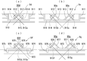
図7を参照し、本発明に係る座具の第5ないし第8実施の形態を説明する。
図7においては、各座具9d~9gの構造と取付構造を簡潔に説明するために、貫通孔、孔口の図示を省略しており、連結ボルトは直線で簡易的に表して符号を省略している。また、梁部材等の木部材の符号も省略している。
図7においては、各座具9d~9gの構造と取付構造を簡潔に説明するために、貫通孔、孔口の図示を省略しており、連結ボルトは直線で簡易的に表して符号を省略している。また、梁部材等の木部材の符号も省略している。
図7に示す各座具9d~9gは、上記座具9~9cの連結ボルトを通す通孔又は螺合する螺合管が一箇所に形成されているのに対し、連結ボルトを通す通孔が二本の連結ボルトを通すことができるように形成されている点で相違している。なお、図7に示す座具9d~9gにおいて、上記座具9~9cと実質的に同等箇所には、同一の符号を付している。
図7(a)に示す第5実施の形態の座具9dは、大体において上記座具9を組み合わせた構造を有している(各座板912は一箇所の座部材90dにまとまっている)。当板910に形成されている通孔915、915aは、各座板912に形成されている各通孔914と同様に図の奥行き方向において位置をずらしてある。
図7(b)に示す第6実施の形態の座具9eは、大体において上記座具9を組み合わせた構造を有している(座板12を有する座部材90eは所要間隔をおいて二箇所にある)。当板910に形成されている通孔915b、915cは、各座板912に形成されている各通孔914と同様に図の奥行き方向において位置をずらしてある。
図7(c)に示す第7実施の形態の座具9fは、大体において上記座具9cの座部材90fに座板926を二箇所に形成した構造を有している。当板923に形成されている通孔915d、915eは、各座板926に形成されている各通孔928と同様に図の奥行き方向において位置をずらしてある。
図7(d)に示す第8実施の形態の座具9gは、大体において上記座具9cで座部材を所要間隔をおいて二箇所に形成した構造、すなわち座部材90gを二箇所に形成した構造を有している。当板923に形成されている通孔915f、915gは、各座板926に形成されている各通孔928と同様に図の奥行き方向において位置をずらしてある。
なお、上記座具9d~9gの作用は、連結ボルトを通す通孔がそれぞれ二箇所に形成されていることで、一つの座具で二本の連結ボルトを引っ張り方向を違えて固定できる点を除き、それぞれ構造の基本となった座具9、9cの作用とほぼ同様であるので、説明を省略する。
図8を参照し、座具を柱部材4と梁部材1、2の接合構造に使用する場合の使用状態を説明する。
この接合構造では、柱部材4と梁部材1の接合には、交差した斜張りの連結ボルト3b、3cが使用され、柱部材4と梁部材2の接合には、交差した斜張りの連結ボルト3d、3eが使用されている。また、この接合構造では、連結ボルト3b、3c及び連結ボルト3d、3eの固定に使用される座具として、各連結ボルトの両端において対となる座具9cと、後で説明する座具9hが使用されている。
この接合構造では、柱部材4と梁部材1の接合には、交差した斜張りの連結ボルト3b、3cが使用され、柱部材4と梁部材2の接合には、交差した斜張りの連結ボルト3d、3eが使用されている。また、この接合構造では、連結ボルト3b、3c及び連結ボルト3d、3eの固定に使用される座具として、各連結ボルトの両端において対となる座具9cと、後で説明する座具9hが使用されている。
座具9hは、連結ボルト3b、3c、3d、3eを回して雌ネジ部934に螺合し固定する構造であるので、対となる側には、同じ座具9hは使用せず、座具9cのようにナット32で締め込むタイプの座具を使用する。このように、連結ボルト3b、3c、3d、3eの一端側の固定を雌ネジ部934への螺合で行うことにより、作業を簡略化できる利点がある。
図9を参照し、座具を持出梁の取付構造に使用する場合の使用状態を説明する。
この接合構造では、持出梁6の柱と梁の接合には、交差方向に配置固定した連結ボルト3h、3iが使用されている。
また、連結ボルト3h、3iの固定に使用される座具として、各連結ボルトの両端において対となる上記座具9cと座具9hが使用されている。なお、連結ボルト3h、3iの一端側の固定を座具9hの雌ネジ部934への螺合で行うことにより、作業を簡略化できる点は、図8に示す接合構造と同様である。
この接合構造では、持出梁6の柱と梁の接合には、交差方向に配置固定した連結ボルト3h、3iが使用されている。
また、連結ボルト3h、3iの固定に使用される座具として、各連結ボルトの両端において対となる上記座具9cと座具9hが使用されている。なお、連結ボルト3h、3iの一端側の固定を座具9hの雌ネジ部934への螺合で行うことにより、作業を簡略化できる点は、図8に示す接合構造と同様である。
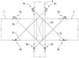
図10を参照し、座具をトラス梁に使用する場合の使用状態を説明する。
この接合構造では、トラス梁構造7の柱とトラス梁の接合には連結ボルト3k、3mが使用され、トラス梁の交差方向に補強のために配置固定した連結ボルト3jが使用されている。また、連結ボルト3k、3mの固定に使用される座具として、各連結ボルトの両端において対となる座具9c及び座具9iが使用され、各連結ボルト3jの固定に使用される座具として、各連結ボルトの両端において対となる座具9c及び座具9h及び座具9iが使用されている。
なお、各連結ボルト3k、3m、3jの一端側の固定を座具9h及び座具9iの雌ネジ部934への螺合で行うことにより、作業を簡略化できる点は、図8、図9に示す接合構造と同様である。
この接合構造では、トラス梁構造7の柱とトラス梁の接合には連結ボルト3k、3mが使用され、トラス梁の交差方向に補強のために配置固定した連結ボルト3jが使用されている。また、連結ボルト3k、3mの固定に使用される座具として、各連結ボルトの両端において対となる座具9c及び座具9iが使用され、各連結ボルト3jの固定に使用される座具として、各連結ボルトの両端において対となる座具9c及び座具9h及び座具9iが使用されている。
なお、各連結ボルト3k、3m、3jの一端側の固定を座具9h及び座具9iの雌ネジ部934への螺合で行うことにより、作業を簡略化できる点は、図8、図9に示す接合構造と同様である。
図11を参照し、本発明に係る座具と共に使用する座具を説明する。
座具9hは、金属製であり、長方形状の当板930と、当板930の両端に直角に形成された縦板931、932を有している。当板930の縦板931、932が設けられている側と同じ側の面(図11で下面)の中央よりやや縦板931寄りには、螺合管933がその中心を通る雌ネジ部934を当板930に貫通させて固着されている。また、螺合管933の中心線方向は、当板930に対し45°の角度に設定されている。
座具9hは、金属製であり、長方形状の当板930と、当板930の両端に直角に形成された縦板931、932を有している。当板930の縦板931、932が設けられている側と同じ側の面(図11で下面)の中央よりやや縦板931寄りには、螺合管933がその中心を通る雌ネジ部934を当板930に貫通させて固着されている。また、螺合管933の中心線方向は、当板930に対し45°の角度に設定されている。
座具9hは、柱部材や梁部材2hの各貫通孔(図11(a)では貫通孔27を図示)の孔口270h(斜面に形成されている)に上記螺合管933の雌ネジ部934を合わせるようにして縦板931、932を梁部材の表面に打ち込み、当板930を梁部材2h表面に密着させて固定する。なお、表面には、螺合管933が収まる凹部20eが予め形成されている。
そして、上記したように貫通孔27に通した連結ボルト3aは、雌ネジ部934に雄ネジ部30をネジ込んで固定される。
そして、上記したように貫通孔27に通した連結ボルト3aは、雌ネジ部934に雄ネジ部30をネジ込んで固定される。
図12(a)に示す座具9iは、大体において上記座具9hの螺合管933を所要の間隔をおいて二箇所に、雌ネジ部934が軸線の角度は違うが互いに向き合うように形成された構造を有している。各螺合管933は、図の奥行き方向において位置をずらしてある。
図12(b)に示す座具9jは、大体において上記座具9hの螺合管を所要の間隔をおいて二箇所に形成した構造、すなわち螺合管933aを二箇所に形成した構造を有すると共に、雌ネジ部934aが軸線の角度は違うが互いに逆方向を向くように形成された構造を有している。各螺合管933aは、図の奥行き方向において位置をずらしてある。
9 座具
90 座部材
910 当板
911 当板
912 座板
913 支持板913
914、915 通孔
916 蓋
J 接合構造
1 梁部材
100 接合面
10、15 座具穴
106 底面
107 内側面
2 梁部材
200 接合面
20、25 座具穴
206 底面
207 内側面
11、21 面
14、24 面
18、28 正面
19、29 背面
17、17a 貫通孔
170、172 孔口
171、173 孔口
27、27a 貫通孔
270、272 孔口
271、273 孔口
3、3a 連結ボルト
30 雄ネジ部
32 ナット
9a 座具
905 当板
906 当板
907 座板
908 通孔
909 通孔
90a 座部材
2a 梁部材
20a 座具穴
206a 底面
207a 内側面
270a 孔口
9b 座具
2b 梁部材
270b 孔口
917 当板
918 縦板
919 座板
920 支持板
921 通孔
922 通孔
90b 座部材
9c 座具
2c 梁部材
270c 孔口
923 当板
924、925 縦板
926 座板
927 支持板
928 通孔
929 通孔
90c 座部材
270c 孔口
9d 座具
90d 座部材
915a 通孔
9e 座具
90e 座部材
915b、915c 通孔
9f 座具
90f 座部材
915d、915e 通孔
9g 座具
90g 座部材
915f、915g 通孔
4 柱部材
3b、3c、3d、3e 連結ボルト
9h 座具
6 持出梁
3h、3i 連結ボルト
7 トラス梁構造
3k、3m 連結ボルト
3j 連結ボルト
9i 座具
9h 座具
930 当板
931、932 縦板
933 螺合管
934 雌ネジ部
2h 梁部材
270h 孔口
20e 凹部
9i 座具
9j 座具
933a 螺合管
934a 雌ネジ部
Claims (2)
- 木質部材の接合部を斜めに交差させた連結ボルトで締め付け固定して接合する接合構造において、連結ボルトの固定に使用する座具であって、
接合する木質部材において荷重に対する耐力が強く変形しにくい木繊維方向と直交する面に当てる板状の第1の当て部材と、
接合する木質部材において荷重に対する耐力が前記木繊維方向と直交する面より弱く変形しやすい木繊維方向の面に当てる板状の第2の当て部材と、
前記第1の当て部材と前記第2の当て部材の一方又は双方の一部と一体的に三角筒状に形成され、該三角筒状部を構成する少なくとも二枚の板部に連結ボルトを通す通孔がそれぞれ形成されており、該通孔が形成された板部のうち前記第1の当て部材又は前記第2の当て部材でない板部が座板となっている座部材とを備える
座具。 - 木質部材の接合部を斜めに交差させた連結ボルトで締め付け固定して接合する接合構造において、連結ボルトの固定に使用する座具であって、
接合する木質部材において、木繊維方向の面に形成され、直方体形状の空間を有する座具穴の平面状の内側面のうち、荷重に対する耐力が強く変形しにくい木繊維方向と直交する内側面に当てる板状の第1の当て部材と、
接合する木質部材において荷重に対する耐力が前記木繊維方向と直交する前記座具穴の内側面より弱く変形しやすい木繊維方向の底面に当てる板状の第2の当て部材と、
前記第1の当て部材と前記第2の当て部材の一方又は双方の一部と一体的に三角筒状に形成され、該三角筒状部を構成する少なくとも二枚の板部に連結ボルトを通す通孔がそれぞれ形成されており、該通孔が形成された板部のうち前記第1の当て部材又は前記第2の当て部材でない板部が座板となっている座部材とを備える
座具。
Applications Claiming Priority (2)
| Application Number | Priority Date | Filing Date | Title |
|---|---|---|---|
| JP2013-003932 | 2013-01-11 | ||
| JP2013003932A JP5613784B2 (ja) | 2013-01-11 | 2013-01-11 | 木質部材の接合構造に使用する座具 |
Publications (1)
| Publication Number | Publication Date |
|---|---|
| WO2014109387A1 true WO2014109387A1 (ja) | 2014-07-17 |
Family
ID=51167033
Family Applications (1)
| Application Number | Title | Priority Date | Filing Date |
|---|---|---|---|
| PCT/JP2014/050330 WO2014109387A1 (ja) | 2013-01-11 | 2014-01-10 | 木質部材の接合構造に使用する座具 |
Country Status (2)
| Country | Link |
|---|---|
| JP (1) | JP5613784B2 (ja) |
| WO (1) | WO2014109387A1 (ja) |
Families Citing this family (1)
| Publication number | Priority date | Publication date | Assignee | Title |
|---|---|---|---|---|
| JP6245592B1 (ja) * | 2017-06-30 | 2017-12-13 | 木構造システム株式会社 | 座具、それを使用した木質部材の接合構造及び木質部材の接合方法 |
Citations (6)
| Publication number | Priority date | Publication date | Assignee | Title |
|---|---|---|---|---|
| JPH01116129A (ja) * | 1987-10-28 | 1989-05-09 | Nippon Jutaku Panel Kogyo Kyodo Kumiai | 柱と基礎の接合装置 |
| JPH08260567A (ja) * | 1995-03-20 | 1996-10-08 | Katsuo Kageyama | 木造建築の筋違い構造 |
| JPH09144133A (ja) * | 1995-09-15 | 1997-06-03 | Fujio Sakata | 軸組工法の木造建築物の鉄筋筋違受金物 |
| JPH11256687A (ja) * | 1998-03-13 | 1999-09-21 | Hatsuo Fujita | 軸組構造及び軸組工法 |
| JP2004143779A (ja) * | 2002-10-23 | 2004-05-20 | Sekisui Chem Co Ltd | ユニット建物 |
| JP2007217949A (ja) * | 2006-02-16 | 2007-08-30 | Kagoshima Univ | 木造部材の接合金具及び接合方法 |
Family Cites Families (4)
| Publication number | Priority date | Publication date | Assignee | Title |
|---|---|---|---|---|
| JPS55124612U (ja) * | 1979-02-24 | 1980-09-04 | ||
| JPS59123721U (ja) * | 1983-02-10 | 1984-08-20 | 株式会社カネシン | 火打ばり締着ボルト用板金製座金 |
| JP2002030730A (ja) * | 2000-05-10 | 2002-01-31 | Nippon Sumikaru:Kk | テーパ座金、板状金具部材、板状金具部材の取付け方法、及び免震補強金具 |
| JP3548090B2 (ja) * | 2000-05-31 | 2004-07-28 | 株式会社カナイ | 座金付きナット、座金付きボルト |
-
2013
- 2013-01-11 JP JP2013003932A patent/JP5613784B2/ja active Active
-
2014
- 2014-01-10 WO PCT/JP2014/050330 patent/WO2014109387A1/ja active Application Filing
Patent Citations (6)
| Publication number | Priority date | Publication date | Assignee | Title |
|---|---|---|---|---|
| JPH01116129A (ja) * | 1987-10-28 | 1989-05-09 | Nippon Jutaku Panel Kogyo Kyodo Kumiai | 柱と基礎の接合装置 |
| JPH08260567A (ja) * | 1995-03-20 | 1996-10-08 | Katsuo Kageyama | 木造建築の筋違い構造 |
| JPH09144133A (ja) * | 1995-09-15 | 1997-06-03 | Fujio Sakata | 軸組工法の木造建築物の鉄筋筋違受金物 |
| JPH11256687A (ja) * | 1998-03-13 | 1999-09-21 | Hatsuo Fujita | 軸組構造及び軸組工法 |
| JP2004143779A (ja) * | 2002-10-23 | 2004-05-20 | Sekisui Chem Co Ltd | ユニット建物 |
| JP2007217949A (ja) * | 2006-02-16 | 2007-08-30 | Kagoshima Univ | 木造部材の接合金具及び接合方法 |
Also Published As
| Publication number | Publication date |
|---|---|
| JP2014134072A (ja) | 2014-07-24 |
| JP5613784B2 (ja) | 2014-10-29 |
Similar Documents
| Publication | Publication Date | Title |
|---|---|---|
| KR20090095443A (ko) | 철골기둥 및 철골빔의 접합구조 | |
| JP5002308B2 (ja) | 木質ラーメン構造における接合構造 | |
| JP3990715B1 (ja) | 木質ラーメン架構 | |
| JP2010281192A (ja) | 建築用接合金具、固定金具、及び、固定ピン | |
| JP3757292B2 (ja) | 木質部材の接合部及び接合用木質部材 | |
| WO2014109387A1 (ja) | 木質部材の接合構造に使用する座具 | |
| JP7252795B2 (ja) | 梁床接合構造 | |
| JP2014109111A (ja) | 梁部材と梁部材との接合構造及び柱部材と梁部材との接合構造 | |
| JP6089241B2 (ja) | 木材接合部の補強部材および木材の接合構造 | |
| JP6934285B2 (ja) | 木質柱梁接合構造 | |
| JP4476358B2 (ja) | 木製柱と木製梁の接合構造 | |
| JP4276007B2 (ja) | 木質強化構造材及び建築物の強化構造体 | |
| JP2013011133A (ja) | 柱と梁の接合構造 | |
| WO2015140894A1 (ja) | 柱構造及びベース部材 | |
| JP4277872B2 (ja) | 木造建築における軸組接合金物及び同接合金物を用いた軸組接合の方法、並びにこれらを構成し用いる共通部材を組み合わせ用いた柱脚接合の方法。 | |
| JP6757218B2 (ja) | 接合構造 | |
| JP7276852B2 (ja) | 木材の接合構造 | |
| JP7449254B2 (ja) | 耐震壁の構築方法 | |
| JP4774319B2 (ja) | 柱と土台の接合装置 | |
| JPH11229494A (ja) | 柱梁取付金物 | |
| JP5437856B2 (ja) | 柱梁接合構造 | |
| JP5571896B2 (ja) | ブレース材 | |
| JP3997020B2 (ja) | 木造住宅用免震接合金物 | |
| JP2018091099A (ja) | コンクリート橋脚用補強金具、コンクリート橋脚用補強器具およびコンクリート橋脚の補強工法 | |
| JP2015094112A (ja) | 木材の接合金具及び木材の接合構造 |
Legal Events
| Date | Code | Title | Description |
|---|---|---|---|
| 121 | Ep: the epo has been informed by wipo that ep was designated in this application |
Ref document number: 14737553 Country of ref document: EP Kind code of ref document: A1 |
|
| DPE1 | Request for preliminary examination filed after expiration of 19th month from priority date (pct application filed from 20040101) | ||
| NENP | Non-entry into the national phase |
Ref country code: DE |
|
| 122 | Ep: pct application non-entry in european phase |
Ref document number: 14737553 Country of ref document: EP Kind code of ref document: A1 |