WO2014091692A1 - タイヤ盗難警報システム - Google Patents
タイヤ盗難警報システム Download PDFInfo
- Publication number
- WO2014091692A1 WO2014091692A1 PCT/JP2013/006923 JP2013006923W WO2014091692A1 WO 2014091692 A1 WO2014091692 A1 WO 2014091692A1 JP 2013006923 W JP2013006923 W JP 2013006923W WO 2014091692 A1 WO2014091692 A1 WO 2014091692A1
- Authority
- WO
- WIPO (PCT)
- Prior art keywords
- vehicle
- tire
- alarm
- air pressure
- acceleration
- Prior art date
- Legal status (The legal status is an assumption and is not a legal conclusion. Google has not performed a legal analysis and makes no representation as to the accuracy of the status listed.)
- Ceased
Links
Images





Classifications
-
- B—PERFORMING OPERATIONS; TRANSPORTING
- B60—VEHICLES IN GENERAL
- B60R—VEHICLES, VEHICLE FITTINGS, OR VEHICLE PARTS, NOT OTHERWISE PROVIDED FOR
- B60R25/00—Fittings or systems for preventing or indicating unauthorised use or theft of vehicles
- B60R25/10—Fittings or systems for preventing or indicating unauthorised use or theft of vehicles actuating a signalling device
- B60R25/102—Fittings or systems for preventing or indicating unauthorised use or theft of vehicles actuating a signalling device a signal being sent to a remote location, e.g. a radio signal being transmitted to a police station, a security company or the owner
-
- B—PERFORMING OPERATIONS; TRANSPORTING
- B60—VEHICLES IN GENERAL
- B60C—VEHICLE TYRES; TYRE INFLATION; TYRE CHANGING; CONNECTING VALVES TO INFLATABLE ELASTIC BODIES IN GENERAL; DEVICES OR ARRANGEMENTS RELATED TO TYRES
- B60C23/00—Devices for measuring, signalling, controlling, or distributing tyre pressure or temperature, specially adapted for mounting on vehicles; Arrangement of tyre inflating devices on vehicles, e.g. of pumps or of tanks; Tyre cooling arrangements
- B60C23/02—Signalling devices actuated by tyre pressure
- B60C23/04—Signalling devices actuated by tyre pressure mounted on the wheel or tyre
- B60C23/0408—Signalling devices actuated by tyre pressure mounted on the wheel or tyre transmitting the signals by non-mechanical means from the wheel or tyre to a vehicle body mounted receiver
- B60C23/0422—Signalling devices actuated by tyre pressure mounted on the wheel or tyre transmitting the signals by non-mechanical means from the wheel or tyre to a vehicle body mounted receiver characterised by the type of signal transmission means
- B60C23/0433—Radio signals
- B60C23/0435—Vehicle body mounted circuits, e.g. transceiver or antenna fixed to central console, door, roof, mirror or fender
- B60C23/0437—Means for detecting electromagnetic field changes not being part of the signal transmission per se, e.g. strength, direction, propagation or masking
-
- B—PERFORMING OPERATIONS; TRANSPORTING
- B60—VEHICLES IN GENERAL
- B60C—VEHICLE TYRES; TYRE INFLATION; TYRE CHANGING; CONNECTING VALVES TO INFLATABLE ELASTIC BODIES IN GENERAL; DEVICES OR ARRANGEMENTS RELATED TO TYRES
- B60C23/00—Devices for measuring, signalling, controlling, or distributing tyre pressure or temperature, specially adapted for mounting on vehicles; Arrangement of tyre inflating devices on vehicles, e.g. of pumps or of tanks; Tyre cooling arrangements
- B60C23/02—Signalling devices actuated by tyre pressure
- B60C23/04—Signalling devices actuated by tyre pressure mounted on the wheel or tyre
- B60C23/0408—Signalling devices actuated by tyre pressure mounted on the wheel or tyre transmitting the signals by non-mechanical means from the wheel or tyre to a vehicle body mounted receiver
- B60C23/0418—Sharing hardware components like housing, antenna, receiver or signal transmission line with other vehicle systems like keyless entry or brake control units
-
- B—PERFORMING OPERATIONS; TRANSPORTING
- B60—VEHICLES IN GENERAL
- B60C—VEHICLE TYRES; TYRE INFLATION; TYRE CHANGING; CONNECTING VALVES TO INFLATABLE ELASTIC BODIES IN GENERAL; DEVICES OR ARRANGEMENTS RELATED TO TYRES
- B60C23/00—Devices for measuring, signalling, controlling, or distributing tyre pressure or temperature, specially adapted for mounting on vehicles; Arrangement of tyre inflating devices on vehicles, e.g. of pumps or of tanks; Tyre cooling arrangements
- B60C23/02—Signalling devices actuated by tyre pressure
- B60C23/04—Signalling devices actuated by tyre pressure mounted on the wheel or tyre
- B60C23/0408—Signalling devices actuated by tyre pressure mounted on the wheel or tyre transmitting the signals by non-mechanical means from the wheel or tyre to a vehicle body mounted receiver
- B60C23/0479—Communicating with external units being not part of the vehicle, e.g. tools for diagnostic, mobile phones, electronic keys or service stations
-
- B—PERFORMING OPERATIONS; TRANSPORTING
- B60—VEHICLES IN GENERAL
- B60C—VEHICLE TYRES; TYRE INFLATION; TYRE CHANGING; CONNECTING VALVES TO INFLATABLE ELASTIC BODIES IN GENERAL; DEVICES OR ARRANGEMENTS RELATED TO TYRES
- B60C23/00—Devices for measuring, signalling, controlling, or distributing tyre pressure or temperature, specially adapted for mounting on vehicles; Arrangement of tyre inflating devices on vehicles, e.g. of pumps or of tanks; Tyre cooling arrangements
- B60C23/02—Signalling devices actuated by tyre pressure
- B60C23/04—Signalling devices actuated by tyre pressure mounted on the wheel or tyre
- B60C23/0486—Signalling devices actuated by tyre pressure mounted on the wheel or tyre comprising additional sensors in the wheel or tyre mounted monitoring device, e.g. movement sensors, microphones or earth magnetic field sensors
- B60C23/0488—Movement sensor, e.g. for sensing angular speed, acceleration or centripetal force
-
- B—PERFORMING OPERATIONS; TRANSPORTING
- B60—VEHICLES IN GENERAL
- B60R—VEHICLES, VEHICLE FITTINGS, OR VEHICLE PARTS, NOT OTHERWISE PROVIDED FOR
- B60R25/00—Fittings or systems for preventing or indicating unauthorised use or theft of vehicles
- B60R25/10—Fittings or systems for preventing or indicating unauthorised use or theft of vehicles actuating a signalling device
- B60R25/1001—Alarm systems associated with another car fitting or mechanism, e.g. door lock or knob, pedals
-
- B—PERFORMING OPERATIONS; TRANSPORTING
- B60—VEHICLES IN GENERAL
- B60R—VEHICLES, VEHICLE FITTINGS, OR VEHICLE PARTS, NOT OTHERWISE PROVIDED FOR
- B60R25/00—Fittings or systems for preventing or indicating unauthorised use or theft of vehicles
- B60R25/30—Detection related to theft or to other events relevant to anti-theft systems
- B60R25/34—Detection related to theft or to other events relevant to anti-theft systems of conditions of vehicle components, e.g. of windows, door locks or gear selectors
Definitions
- This disclosure relates to a tire theft alarm system.
- Patent Literature 1 discloses a technique in which a vehicle issues a warning by sound and light when a change in tire air pressure when a tire is removed from the vehicle is detected.
- the technology using light and sound as described above can be an effective means for notifying the user of an abnormality when the distance between the vehicle parking position and the user position (for example, a house) is long. Absent.
- the tire theft alarm system includes an on-vehicle device disclosure mounted on a vehicle disclosure and a portable device disclosure carried by a user of the vehicle.
- the vehicle-mounted device detects and transmits the pressure of the tire disclosed in the tire or the acceleration applied to the tire mounted on the vehicle. Based on the change, a radio wave including the first alarm is transmitted.
- the portable device issues a warning notification to the user based on the reception of the radio wave including the first warning transmitted by the vehicle-mounted device.
- the vehicle-mounted device transmits the first alarm by radio wave based on the change in the tire pressure or acceleration, and the portable device receives the radio wave to warn the user. Notification. Therefore, even when the vehicle issues a sound and light alarm, the first alarm is notified from the in-vehicle device to the portable device by radio waves, so that the user can be informed of the theft of the tire.
- the vehicle-mounted device controls the display in accordance with the tire air pressure received from the sensor transmitter when the main power is on and stops operating when the main power is off.
- TPMS on-board device disclosure and at least door control on-vehicle device disclosure that controls locking and unlocking of the vehicle door by communicating with the portable device when the main power is off.
- the sensor transmitter transmits the detected tire air pressure to the TPMS on-board device, and when the main power is off, the sensor transmitter detects the detected tire air pressure.
- the door control on-board unit transmits the radio wave to the portable unit based on the change in the tire air pressure received from the sensor transmitter. Send the first alarm.
- the first alarm can be transmitted to the portable device using the door control vehicle-mounted device that operates at least when the traveling drive power is off, it is not necessary to operate the TPMS on-vehicle device when the traveling drive power is off. . Therefore, it is not necessary to extend the operating time of the TPMS on-board device that is assumed to be operated during travel and is not designed to reduce power consumption, and to reduce the power consumption of the vehicle without the need to extend the operating time for warning of tire theft. it can.
- the drawing 1 is a configuration diagram of a tire theft alarm system according to a first embodiment of the present disclosure. It is a block diagram of a sensor transmitter. It is a flowchart of the process which TPMS onboard equipment performs. It is a flowchart of the process which a door control vehicle-mounted device performs in 1st Embodiment. It is a sequence diagram of operation
- the tire theft alarm system is attached to each of a plurality of tires 1a to 1d mounted on a vehicle 10 that travels with the power of an engine that is an internal combustion engine.
- Sensor transmitters 2a to 2d a TPMS (tire pressure monitoring system) vehicle-mounted device 3, a door control vehicle-mounted device 4, a wide-area communication device 5 mounted on the vehicle body of the vehicle 10, and a key portable device 30 carried by the user of the vehicle 10 And.
- TPMS tire pressure monitoring system
- Each of the sensor transmitters 2a to 2d always operates regardless of whether the vehicle IG is on or off (the vehicle main power is on or off). Then, the air pressure of the tires 1a to 1d to be attached and the acceleration applied to the tire due to vibration, rotation, etc. of the tire (for example, acceleration in the radial direction of the tire) are detected, and the latest detected value (air pressure) And acceleration) periodically and periodically.
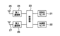
- each of the sensor transmitters 2a to 2d includes an air pressure sensor 21, an acceleration sensor 22, a control unit 23, a first communication unit 24, a first antenna 25, and a second communication unit, as shown in FIG. 26 and the second antenna 27 are provided.
- the units 21 to 27 are driven based on power supply from a battery (not shown) provided in the sensor transmitter.
- the air pressure sensor 21 is constituted by a diaphragm type pressure sensor, for example, and outputs a detection signal corresponding to the air pressure of the tire at the attachment destination.
- the acceleration sensor 22 is used to detect acceleration (acceleration due to movement and rotation, and gravitational acceleration) applied to the tire due to vibration, rotation, and the like of the mounting destination tire. A detection signal corresponding to the acceleration in the radial direction is output.
- the control unit 23 is a microcomputer including a CPU, a memory, and the like, and executes a predetermined process according to a program stored in the memory. Specifically, the control unit 23 periodically and repeatedly acquires tire pressure information based on the detection signal output from the air pressure sensor 21, and information on acceleration based on the detection signal output from the acceleration sensor 22. Are periodically acquired, both the tire air pressure information and the acceleration information are stored in the frame, and the frame is transmitted at a predetermined periodic timing.
- the transmission destination may be the TPMS on-board unit 3 or the door control on-board unit 4 in some cases.
- the first communication unit 24 is a wireless transmission circuit that performs processing such as amplification and modulation on a frame to be transmitted, and transmits the resulting signal to the first antenna 25.
- the second communication unit 26 is a wireless transmission circuit that performs processing such as amplification and modulation on a frame to be transmitted, and transmits the resulting signal to the second antenna 27.
- the first communication unit 24 and the first antenna 25 are configured to transmit a frame to the TPMS on-vehicle device 3, and the second communication unit 26 and the second antenna 27 are configured to transmit a frame to the door control on-vehicle device 4. It is the composition.
- the first communication unit 24 uses a frequency (for example, 314.98 MHz), a modulation scheme (for example, FSK), the TPMS onboard device 3 can receive the frame, And a signal with a data rate (for example, several tens of kbps) is transmitted to the first antenna 25.
- a frequency for example, 314.98 MHz
- a modulation scheme for example, FSK
- FSK modulation scheme
- the TPMS onboard device 3 can receive the frame
- a signal with a data rate for example, several tens of kbps
- the second communication unit 26 receives the frame at a frequency (for example, 314.35 MHz) that can be received by the door control vehicle-mounted device 4 and a modulation method (for example, The signal may be FSK or ASK) and a data rate (for example, several kbps) and transmitted to the second antenna 27.
- a frequency for example, 314.35 MHz
- the signal may be FSK or ASK
- a data rate for example, several kbps
- the first communication unit 24 also has a function of demodulating a signal (for example, an IG off notification signal) transmitted from the TPMS on-vehicle device 3 and received by the first antenna 25 and outputting the resultant data to the control unit 23. is doing.
- a signal for example, an IG off notification signal
- first antenna 25 and the second antenna 27 may be configured to be combined into one as long as both the frequency that can be received by the TPMS on-board unit 3 and the frequency that can be received by the door control on-board unit 4 can be covered.
- the TPMS vehicle-mounted device 3 is attached to the body of the vehicle 10, and during operation, displays according to the tire pressure and acceleration received wirelessly from the sensor transmitters 2a to 2d (for example, display of air pressure and acceleration to a meter) To control.
- the TPMS in-vehicle device 3 of the present embodiment includes a wireless transmission unit for transmitting an IG OFF notification to each of the sensor transmitters 2a to 2d.
- the door control vehicle-mounted device 4 operates both when the IG is on and when it is off, and controls the locking and unlocking of the door of the vehicle 10 by communicating with the key portable device 30 during the operation. For example, when a door lock signal is received from the key portable device 30, the door is locked, and when a door unlock signal is received from the key portable device 30, the door is unlocked.
- the door control vehicle-mounted device 4 transmits a request signal to the key portable device 30, receives an answer signal from the key portable device 30 as a response to the request signal, and further touches the door knob based on the user touching the door knob. May be unlocked.
- the door lock signal is a signal transmitted from the key portable device 30 based on the user performing a predetermined door lock operation on the key portable device 30.
- the door unlock signal is a signal transmitted by the key portable device 30 when the user performs a predetermined door unlock operation on the key portable device 30.
- the door control vehicle-mounted device 4 of the present embodiment has a wireless transmission unit for transmitting the first alarm to the key portable device 30.
- the wide area communication device 5 is a wireless communication unit for communicating with a destination farther than the transmission range of the first alarm, and operates even when the IG is on or off.
- a center 33 (corresponding to an example of a transmission destination) connected to the communication network 32 by wirelessly connecting to a wireless base station 31 connected to the communication network 32 (cellular communication network, Internet, etc.) Communicate with. Further, it communicates with a user terminal 35 (corresponding to an example of a transmission destination) such as a smart phone via another wireless base station 34 connected to the communication network 32.
- the user terminal 35 is a terminal carried by the user of the vehicle 10, but is a terminal different from the key portable device 30.
- a wide-area communication device 5 a well-known DCM (Data Communication Module) can be used.
- the wireless communication range of the wide area communication device 5 is far wider than the transmission range of the first alarm by the door control vehicle-mounted device 4 (for example, within a radius of 30 meters centered on the door control on-vehicle device 4) (for example, wide area). (Within a radius of 5 kilometers centered on the communication device 5).
- the key portable device 30 is carried by the user of the vehicle 10 and communicates with the door control vehicle-mounted device 4. By this communication, the door control vehicle-mounted device 4 controls the locking and unlocking of the door of the vehicle 10 as described above.
- the key portable device 30 may be a known smart key (a key used for smart entry) or a known RKE key (a key used for keyless entry).
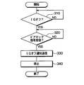
- the TPMS in-vehicle device 3 transmits the IG OFF notification to the sensor transmitters 2a to 2d and stops the processing shown in FIG. 3 simultaneously with the processing for display according to the tire pressure and acceleration described above. Also comes to run.
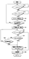
- the door control vehicle-mounted device 4 is configured to execute the processing shown in FIG. 4 both when the IG is on and when it is off. First, the operation from before the IG off to the warning notification in the key portable device 30 will be described with reference to FIG. 3, FIG. 4, and FIG.
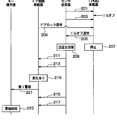
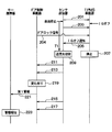
- each of the sensor transmitters 2a to 2d detects the air pressure and acceleration of the tires 1a to 1d to which they are attached while the IG is on, and repeatedly and periodically indicates signals indicating the latest detection values (air pressure and acceleration). 201 is transmitted to TPMS onboard equipment 3.
- TPMS onboard equipment 3 In FIGS. 5 and 7, only one arbitrary sensor transmitter 2a to 2d is shown for simplicity, but the operation of the other sensor transmitters is basically the same.
- the TPMS vehicle-mounted device 3 controls the display of the pressure of each tire 1a to 1d (for example, the control to display the pressure and acceleration of each tire on a meter). )I do.
- the TPMS on-vehicle device 3 determines that the IG is not OFF (ON) in step 310 based on the voltage of the IG signal line (not shown) in the process of FIG. Repeat the determination process.
- step 105 the door control vehicle-mounted device 4 makes a determination based on the voltage of an IG signal line (not shown), and as a result, the determination process in step 105 is repeated.
- the TPMS on-vehicle device 3 determines that the IG is turned off in step 310 based on the voltage of the IG signal line (not shown) in the process of FIG. It is determined that no signal has been received, and the process of step 320 is repeated.
- the door control vehicle-mounted device 4 makes a determination based on the voltage of an IG signal line (not shown), and as a result, proceeds to step 110 and the door is not locked. Determine and repeat the process of step 110.
- each of the sensor transmitters 2a to 2d detects the air pressure and acceleration of the tires 1a to 1d to which they are attached and repeatedly and periodically updates the latest information.
- a signal 203 indicating the detected value (air pressure and acceleration) is transmitted to the TPMS on-vehicle device 3. Further, the TPMS on-board unit 3 performs display control of the tire pressures of the tires 1a to 1d based on the received tire pressure and acceleration signals (signal 203, etc.).
- step 115 the door lock signal 204 is output to the TPMS on-vehicle device 3, and the state shifts to a warning state.
- the TPMS on-vehicle device 3 that has received this door lock signal 204 determines that it has received the door lock signal in step 320 and proceeds to step 330.
- the IG-off notification signal 205 is transmitted to each of the sensor transmitters 2a to 2d, and then the operation is stopped in step 340 (step 207 in FIG. 5).
- Each of the sensor transmitters 2a to 2d that has received the IG-off notification signal 205 performs transmission destination switching processing (step 209) so that the transmission destination of the detected tire air pressure and acceleration is transferred from the TPMS in-vehicle device 3 to the door. Switch to the control vehicle-mounted device 4.
- a frame including the tire air pressure information and the acceleration information is output to the first communication unit 24, thereby including a signal including the frame (for example, the signal 201, 203) was transmitted to the TPMS on-board unit 3.
- the output destination of the frame including tire pressure information and acceleration information is switched from the first communication unit 24 to the second communication unit 25.
- the second communication unit 25 wirelessly transmits the signal of the frame (for example, signals 211, 213, 215, and 217 described later) to the door control vehicle-mounted device 4 instead of the TPMS vehicle-mounted device 3. Send.
- the content of the frame to be output is switched depending on whether the frame is output to the first communication unit 24 or the second communication unit 26.
- the frame when outputting to the first communication unit 24, the frame is configured and output in the frame format for the TPMS on-vehicle device 3, and when outputting to the second communication unit 26, the door control on-vehicle device.
- a frame is configured with a frame format for 4 and output.
- the frame format for the TPMS on-vehicle device 3 and the frame format for the door control on-vehicle device 4 are different.
- the frame format for the door control on-vehicle device 4 is the same as the frame format of the door lock signal and the door unlock signal (hereinafter referred to as RKE format) transmitted from the key portable device 30 to the door control on-vehicle device 4. Then, TPMS data (air pressure, acceleration, etc. data) is included in the RKE format data area (area for storing the encrypted code).
- RKE format the frame format of the door lock signal and the door unlock signal
- tag information indicating that the data is transmitted by the sensor transmitters 2a to 2d is included in the key ID area (area for storing the ID of the key portable device 30) in the RKE format or the data area.
- the door control vehicle-mounted device 4 determines whether the received frame is from the sensor transmitters 2a to 2d or the key portable device 30 based on the presence or absence of the tag information. Can be determined.
- the TPMS in-vehicle device 3 resumes its operation when the IG is turned on later, and transmits an IG on notification signal (not shown) to each of the sensor transmitters 2a to 2d.
- the sensor transmitters 2a to 2d switch the transmission destination of the detected tire pressure and acceleration from the door control vehicle-mounted device 4 to the TPMS vehicle-mounted device 3 based on the reception of the IG-on notification.
- the door control vehicle-mounted device 4 waits for reception of a frame signal including the tag information (for example, one of signals 211, 213, 215, and 217). Then, it is determined whether or not both physical quantities included in the frame (that is, a set of tire air pressure and acceleration) have exceeded a predetermined reference.
- a frame signal including the tag information for example, one of signals 211, 213, 215, and 217.
- an air pressure change reference value for comparison with the absolute value of the change amount of the air pressure obtained this time (that is, the latest) with respect to the reference air pressure recorded in advance is adopted. More specifically, the absolute value of the amount of change when the tire is deflated to steal the tire exceeds the air pressure change reference value, and the amount of change due to a slight load change such as a cat jumping on the vehicle body
- the air pressure change reference value is set in advance so that the absolute value does not exceed the air pressure change reference value.
- the air pressure of the same tire when a certain time (for example, 1 minute) has passed since the engine of the vehicle 10 stopped may be recorded and used.
- the air pressure of the same tire at the time (for example, the air pressure of the same tire included in the first frame 211 after the time when the door lock signal 204 is transmitted) may be recorded and used.
- an acceleration change reference value for comparison with the absolute value of the change amount of acceleration acquired this time (that is, the latest) with respect to the reference acceleration recorded in advance is adopted. More specifically, the acceleration change reference value is set in advance so that the absolute value of the change amount when the wheel nut attached to the tire is loosened to steal the tire exceeds the acceleration change reference value. Keep it.
- the acceleration of the same tire at the time when a certain time (for example, 1 minute) has passed since the engine of the vehicle 10 stopped may be recorded and used. You may record and use the acceleration of the same tire at the time.
- step 120 If the absolute value of the difference between the air pressure received by the door control vehicle-mounted device 4 this time and the reference air pressure is equal to or less than the air pressure change reference value, it is determined in step 120 that there is no change. Also, if the absolute value of the difference between the acceleration currently received by the door control vehicle-mounted device 4 and the reference acceleration is equal to or less than the acceleration change reference value, it is determined in step 120 that there is no change.
- step 120 is executed again through steps 105, 110, and 115. As described above, the state in which the determinations in steps 105, 110, 115, and 120 are repeated continues until it is determined in step 120 that there is a change.
- the absolute value of the difference between the air pressure received by the door control vehicle-mounted device 4 and the reference air pressure exceeds the air pressure change reference value, and the absolute difference between the acceleration received by the door control on-vehicle device 4 and the reference acceleration is absolute. If the value exceeds the acceleration change reference value, it is determined in step 120 that there is a change (see step 219 in FIG. 5), and the process proceeds to step 130.
- the cause of the determination that there has been a change in step 120 is, for example, that a tire thief prevents a vehicle body from being lowered by sandwiching a brick or the like under the vehicle body, and the tires 1a to 1d.
- the air pressure of the one tire suddenly drops.
- the tire theft criminals put a brick or the like under the car body so that the car body does not go down.
- vibration is generated in the one tire, and as a result, the acceleration applied to the one tire may be drastically decreased.
- the first alarm 221 is transmitted to the key portable device 30 by radio waves (for example, radio waves in the RF band) in order to notify the user of a sign of tire theft.
- the key portable device 30 that has directly received this radio wave within the transmission range of the first alarm 221 is a user carrying the key portable device 30 based on the fact that the first alarm 221 is included in the received radio wave.
- a warning notification is performed (step 223).
- the warning notification method may be a method of operating a vibration generating device attached to the key portable device 30, a method of operating a light emitting device attached to the key portable device 30, or a method attached to the key portable device 30. Alternatively, a method of operating a sound generator may be used.
- the door control vehicle-mounted device 4 transmits the first alarm 221 by radio waves based on the change in the tire pressure or acceleration, and the key portable device 30 directly transmits the radio waves. Receiving and alerting the user. Therefore, even when the vehicle 10 itself issues a sound and light alarm, it is difficult to be transmitted to the user (for example, when the vehicle 10 is stopped at the entrance of the user's house and the user is in the user's house). Since the first alarm is notified from the door control vehicle-mounted device 4 to the key portable device 30, it is possible to notify the user of tire theft.
- the door control vehicle-mounted device 4 proceeds to step 140 in FIG. 4 to determine whether or not a callback is received from the key portable device 30. Proceed to step 150. In step 150, it is determined whether any one of the received signal strengths (RSSI) of the radio waves received from the sensor transmitters 2a to 2d has changed beyond a predetermined reference.
- RSSI received signal strengths
- an intensity change reference value for comparison with the absolute value of the signal intensity change amount is adopted. More specifically, the intensity change reference value is set in advance so that the absolute value of the change amount when the tire is removed from the vehicle body in order to steal the tire exceeds the intensity change reference value.
- step 150 determines that there is no change, and proceeds to step 160.
- step 160 it is determined whether or not a predetermined period (for example, 1 minute, 5 minutes, or 10 minutes) has elapsed since the last transmitted first alarm 221 was transmitted. If not, return to Step 140.
- a predetermined period for example, 1 minute, 5 minutes, or 10 minutes
- the door control vehicle-mounted device 4 repeats steps 140, 150, and 160 in this order.
- the callback operation 225 may be, for example, a pressing operation of a button dedicated to the callback operation attached to the key portable device 30, or a door lock button and a door unlock button attached to the key portable device 30.
- the simultaneous pressing operation may be used.
- the key portable device 30 transmits a predetermined callback 227 by radio waves based on the presence of the callback operation 225.
- the transmission unit used for transmitting the callback may be the same as the transmission unit for transmitting the door lock signal and the door unlock signal or the answer signal described above, or a different transmission unit may be used. Also good.
- the frequency of the radio wave including the callback modulation method and the callback signal is the same as that of the door lock signal and the door unlock signal or the answer signal.
- step 180 the alarm is canceled (step 229 in FIG. 6), and the process returns to step 105.
- the door control vehicle-mounted device 4 changes the intensity exceeding the intensity change reference value in the reception intensity from any of the sensor transmitters 2a to 2d before the predetermined period has elapsed since the transmission of the first alarm 221. If no callback is received from the key portable device 30 when there is not, the alarm is canceled without transmitting a second alarm request to be described later.
- the fact that the callback is received within the predetermined period means that the user has noticed the warning notification based on the first alarm.
- the first alarm 221 is transmitted due to the above-described action by the tire thief (ie, deflation of the tire, jack-up)
- the user should immediately go to the location of the vehicle 10 to confirm the cause of the warning notification. There is no need to send the second alarm to the destination.
- the first alarm 221 is transmitted due to the user's own work such as car washing, it is clear that the tire is not stolen, so there is no need to transmit the second alarm to the remote destination.
- a communication fee, service fee, etc. are often required, so by not sending the second alarm unnecessarily, you can reduce the communication fee, service fee, etc. Can be saved.
- the door control vehicle-mounted device 4 does not receive a callback as in the first operation example, and the received intensity from any of the sensor transmitters 2 a to 2 d Steps 140, 150, and 160 are repeated in this order as long as there is no change exceeding the intensity change reference value and a predetermined period has not elapsed since the transmission of the first alarm 221.
- the received signal strength (RSSI) of the radio wave received from one of the sensor transmitters 2 a to 2 d changes more than a predetermined standard. Suppose there was.
- the door control vehicle-mounted device 4 periodically receives the tire air pressures 231, 233, 235, and 237 by radio waves from each of the sensor transmitters 2a to 2d.
- the received signal strength of the previous tire pressure 235 received from a specific sensor transmitter is compared with the latest (that is, the current) tire pressure 237 received signal strength, the latter change with respect to the former It is assumed that the absolute value of the quantity exceeds the intensity change reference value.
- Such a situation occurs, for example, when the first one of the four tires targeted by the tire thief is removed from the vehicle body.
- the door control vehicle-mounted device 4 determines in step 150 in FIG. 4 that there is a change in the signal reception intensity (step 239 in FIG. 7), and proceeds to step 170.
- step 170 a request 241 for transmitting the second alarm to the remote transmission destination is output to the wide area communication device 5.
- the wide area communication device 5 that has received the request 241 transmits a second alarm to a predetermined remote destination (step 243).
- the second alarm may include vehicle 10 identification information (such as license plate information) and vehicle 10 position information.
- vehicle 10 identification information such as license plate information
- vehicle 10 position information such as license plate information
- the position information of the vehicle 10 may be obtained from, for example, a GPS receiver mounted on the vehicle.
- the center 33 In the center 33 that has received this second alarm, the center 33 automatically or the operator of the center 33 notifies the security company or the like that there is a risk of tire theft using a telephone or the like.
- This notification includes identification information and position information of the vehicle 10.
- the security company that has received this report can take action in response to tire theft to prevent damage from theft or to minimize damage.
- the wide area communication device 5 wirelessly connects to the nearest base station 31 to thereby establish a communication network 32.
- the second alarm same as the above is transmitted by e-mail, for example, to the user terminal 35 existing within the communication range of the base station 34 via the base station 34 connected to (step 243).
- the user terminal that has received the second alarm displays the content of the second alarm to the user and notifies the user that there is a risk of tire theft.
- the damage of the tire can be prevented or the damage can be minimized.
- the first alarm is received by the key portable device 30, but even if the first alarm does not reach the key portable device 30, the door control vehicle-mounted device 4 and the wide area communication device There is no change in the operation of 5.
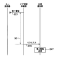
- the door control vehicle-mounted device 4 does not receive a callback as in the first operation example, and the received intensity from any of the sensor transmitters 2 a to 2 d Steps 140, 150, and 160 are repeated in this order as long as there is no change exceeding the intensity change reference value and a predetermined period has not elapsed since the transmission of the first alarm 221.
- a predetermined period 30 has elapsed since the transmission of the first alarm 221 while no callback is received and the received intensity from any of the sensor transmitters 2a to 2d does not exceed the intensity change reference value. To do.
- the user carrying the key portable device 30 is located far from the vehicle 10 (for example, the user's commuting destination when the vehicle 10 is at home), and the thief wears a tire.
- the signal reception intensity does not change within the predetermined period 30, or the thief uses some clever means to remove the tire without changing the signal reception intensity.
- the first alarm does not reach the key portable device 30, and a predetermined period elapses from the transmission of the first alarm 221 while the received intensity does not change beyond the intensity change reference value.
- the door control vehicle-mounted device 4 determines in step 160 of FIG. 4 that a predetermined period has elapsed since the transmission of the first alarm, and proceeds to step 170.
- a request 245 for transmitting the second alarm to the remote transmission destination is output to the wide area communication device 5.
- the wide area communication device 5 that has received the request 241 transmits a second alarm to a predetermined remote destination (step 247).
- the specific method for transmitting the second alarm is the same as that in Step 243 of the second operation example. In this way, as in the second operation example, damage from tire theft can be prevented in advance, or damage can be minimized even if it is not.
- a first alarm is transmitted to the key portable device 30 based on a change in the air pressure and acceleration of any tire, and thereafter, from the sensor transmitters 2a to 2d. If the received signal strength changes, or if there is no callback within the predetermined period 30 even if the received signal strength from the sensor transmitters 2a to 2d does not change, the second alarm is sent to the remote center 33 or the user. Transmit to the terminal 35.
- the data receivers of the sensor transmitters 2a to 2d are switched to the door control vehicle-mounted device 4 that is always in a standby state. Therefore, it is determined that the tire is likely to be stolen when there is a change in the tire pressure and acceleration from the initial parking state because the vehicle 10 is jacked up, a block or the like is put under the vehicle and the tire air is removed. And a 1st alarm can be made using the door control vehicle equipment 4 as a theft sign. Therefore, the initial movement of the user is accelerated. Moreover, since the wide area communication device 5 is not used suddenly, it is possible to suppress useless communication costs.
- the emergency earthquake prediction bulletin is a bulletin that notifies the user in advance of the occurrence of an earthquake (or a major motion caused by an earthquake), and can be received by the wide area communication device 5.
- the wide area communication device 5 receives this emergency earthquake prediction bulletin, it notifies the door control vehicle-mounted device 4 that the emergency earthquake prediction bulletin has been received.
- the door control vehicle-mounted device 4 determines whether or not an emergency earthquake prediction bulletin has been received depending on whether or not this notification has been received.
- step 117 If it is determined in step 117 that the emergency earthquake prediction bulletin has not been received, the process proceeds to step 120. Therefore, the determination in steps 105, 110, 115, 117, and 120 is repeated while it is in the alert state, has not received the emergency earthquake prediction breaking news, and has determined that there is no change in step 120. The operation after it is determined in step 120 that there is a change is the same as in the first embodiment.
- the sensor transmitters 2a to 2d since the sensor transmitters 2a to 2d receive the IG-off notification, the sensor transmitters 2a to 2d detect the arrival of the switching timing of the transmission destination of the frame including the air pressure and acceleration based on the tire air pressure and acceleration detected by itself.
- the operations of the devices other than the sensor transmitters 2a to 2d and the TPMS on-vehicle device 3 are the same as those in the first and second embodiments.
- step 320 The operation of the TPMS in-vehicle device 3 is different from that of the first and second embodiments.
- the process proceeds to step 340 without executing step 330. It is only the point which advances and stops the operation (step 207 in FIG. 5).
- control for switching the transmission destination of the frame realizes the switching of the transmission destination of the frame by performing the processing shown in the flowcharts of FIGS. .
- FIG. 12 is an alternative to the operation shown in FIG. Note that the operations in FIGS. 6 to 8 are executed in the same manner in this embodiment. Hereinafter, the operation of FIG. 12 will be described with respect to differences from the operation of FIG.
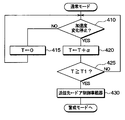
- control unit 23 of each of the sensor transmitters 2a to 2d executes the process of FIG. 10 in the normal mode, and determines whether or not the acceleration change is stopped in Step 410.
- the maximum value and the minimum value are extracted from the detected accelerations of the past several times (for example, twice) including the latest acceleration detected using the acceleration sensor 22, and the difference between the maximum value and the minimum value is predetermined. If it is less than a threshold acceleration (for example, acceleration equal to gravitational acceleration), it is determined that the acceleration change has stopped. In other cases, it is determined that the acceleration change has not stopped.
- a threshold acceleration for example, acceleration equal to gravitational acceleration
- step 415 the value of the time variable T is reset to zero, and the process returns to step 410. Therefore, before the vehicle stops, the processes of steps 410 and 415 are repeated.
- the control unit 23 detects the air pressure and acceleration of the tires 1a to 1d to which the tires are attached, and uses the first communication unit 24 and the first antenna 25 to indicate the latest detection values (air pressure and acceleration) ( For example, the signal 201) is repeatedly and periodically transmitted to the TPMS vehicle-mounted device 3.
- FIGS. 5 and 7 only one arbitrary sensor transmitter 2a to 2d is shown for simplicity, but the operation of the other sensor transmitters is basically the same.
- the TPMS vehicle-mounted device 3 controls the display of the pressure of each tire 1a to 1d (for example, the control to display the pressure and acceleration of each tire on a meter). )I do.
- the TPMS on-vehicle device 3 determines that the IG is not OFF (ON) in step 310 based on the voltage of the IG signal line (not shown) in the process of FIG. Repeat the determination process.
- step 105 the door control vehicle-mounted device 4 makes a determination based on the voltage of an IG signal line (not shown), and as a result, the determination process in step 105 is repeated.
- step 410 the acceleration change has stopped.
- step 420 the value of the time variable T is increased by a predetermined increment ⁇ .
- This predetermined increment ⁇ corresponds to the repetition period of step 420 when steps 410, 420, and 425 are repeated in this order.
- step 425 it is determined whether or not the time variable T is equal to or longer than the predetermined time T1, and if it is equal to or longer than the predetermined time T1, the process returns to step 410. While the vehicle continues to stop, the control unit 23 repeats steps 410, 420, and 425, whereby the time variable T increases in synchronization with the elapsed time from when the acceleration does not change for the first time.
- the TPMS on-vehicle device 3 determines that the IG is turned off in step 310 based on the voltage of the IG signal line (not shown) in the process of FIG. It is determined that the door lock signal has not been received, and the process of step 320 is repeated.
- the door control vehicle-mounted device 4 makes a determination based on the voltage of an IG signal line (not shown), and as a result, proceeds to step 110 and the door is not locked. Determine and repeat the process of step 110.
- step 115 the door lock signal 204 is output to the TPMS on-vehicle device 3, and the state shifts to a warning state.
- the TPMS on-vehicle device 3 that has received the door lock signal 204 determines that the door lock signal has been received in step 320, bypasses step 330, and proceeds to step 340.
- step 340 the operation is stopped (step 207 in FIG. 5).
- each control unit 23 of the sensor transmitters 2a to 2d it is assumed that the time variable T that has been increased by the repetition of step 420 becomes equal to or longer than a predetermined time T1 (for example, 5 minutes). Then, the control unit 23 determines in step 425 that the time variable T is equal to or greater than the predetermined time T1, and proceeds to step 430. Thus, the control unit 23 determines that the vehicle has stopped based on the fact that the acceleration change has stopped for a predetermined time T1 or more.
- step 430 the control unit 23 of each of the sensor transmitters 2a to 2d performs transmission destination switching processing (step 209), so that the transmission destination of the frame including the detected tire air pressure and acceleration is determined.
- step 209 transmission destination switching processing
- the process transits to a warning mode and starts executing the process of FIG.
- the second communication unit 25 sends the signal of the frame (for example, signals 211, 213, 215, and 217 described later) to the door control vehicle-mounted device instead of the TPMS vehicle-mounted device 3. 4 is transmitted wirelessly.
- the signal of the frame for example, signals 211, 213, 215, and 217 described later
- step 410 it is first determined in step 410 whether or not the air pressure change amount exceeds a predetermined threshold amount P1.
- the air pressure increase amount is the latest air pressure increase amount detected by using the air pressure sensor 21 with respect to the reference air pressure.
- the reference air pressure for example, the detected value of the air pressure immediately before or immediately after the last transition from the normal mode to the alert mode is adopted. It is determined whether or not a person has boarded the vehicle based on whether or not the amount of increase in air pressure exceeds a predetermined threshold amount P1.
- step 450 While the person is not in the vehicle, the air pressure increase amount does not exceed the threshold amount P1, and the process of step 450 is repeated. Thereafter, when a person gets on the vehicle, it is determined in step 450 that the air pressure increase amount exceeds the threshold amount P1, and the process proceeds to step 455.
- step 455 it is determined whether or not the acceleration has changed. Specifically, the maximum value and the minimum value are extracted from the detected accelerations of the past several times (for example, twice) including the latest acceleration detected using the acceleration sensor 22, and the difference between the maximum value and the minimum value is predetermined. If it is equal to or greater than a threshold acceleration (for example, acceleration equal to gravitational acceleration), it is determined that there is an acceleration change. In other cases, it is determined that there is no acceleration change, and the process returns to step 450. Even if a person gets on the vehicle, if the vehicle does not start to travel, it is determined in step 455 that there is no change in acceleration, so the processing in steps 450 and 455 is repeated.
- a threshold acceleration for example, acceleration equal to gravitational acceleration
- step 450 it is determined in step 450 that the air pressure increase amount exceeds the threshold amount P1, and in step 455, it is determined that there is a change in acceleration, so the process proceeds to step 460.
- step 460 the control unit 23 of each of the sensor transmitters 2a to 2d performs transmission destination switching processing, so that the transmission destination of the frame including the detected tire pressure and acceleration is transmitted from the door control vehicle-mounted device 4 to the TPMS vehicle-mounted device. Switch to vessel 3. Thereafter, the process returns to the normal mode, and the process of FIG. 10 is started.
- the specific method of switching the transmission destination in step 460 is realized by switching the output destination of the frame including the tire air pressure information and the acceleration information from the second communication unit 25 to the first communication unit 24. Therefore, after the switching, the first communication unit 24 wirelessly transmits the signal of the frame to the TPMS onboard unit 3 instead of the door control onboard unit 4.
- the content of the output frame is changed to the frame format for TPMS OBE 3.
- the on / off of the IG of the vehicle 10 that runs with the power of the engine that is the internal combustion engine is cited as an example of the on / off of the main power supply of the vehicle.
- the vehicle 10 is an electric vehicle that runs with the power of the electric motor, the main power supply of the vehicle does not have to be turned on or off.
- the door control vehicle-mounted device 4 determines that the absolute value of the difference between the air pressure received this time by the door control vehicle-mounted device 4 and the reference air pressure exceeds the air pressure change reference value in step 120 of FIG. And only when the absolute value of the difference between the acceleration received by the door control vehicle-mounted device 4 this time and the reference acceleration exceeds the acceleration change reference value, the routine proceeds to step 130.
- step 120 of FIG. 4 the absolute value of the difference between the air pressure received by the door control vehicle-mounted device 4 and the reference air pressure exceeds the air pressure change reference value, or the door control vehicle-mounted device 4 received this time.
- the process may proceed to step 130, and otherwise, the process may return to step 105.
- the key portable devices 30, such as a smart key and a RKE key are illustrated as an example of a portable device.
- the portable device of the present disclosure is not limited to a communication device for locking and unlocking a vehicle door, and may be a portable device such as a mobile phone or a PDA.
Landscapes
- Engineering & Computer Science (AREA)
- Mechanical Engineering (AREA)
- Physics & Mathematics (AREA)
- Electromagnetism (AREA)
- Burglar Alarm Systems (AREA)
- Lock And Its Accessories (AREA)
- Emergency Alarm Devices (AREA)
Abstract
Description
以下、本開示の第1実施形態について説明する。図1に記載の通り、本実施形態に係るタイヤ盗難警報システムは、内燃機関であるエンジンの動力で走行する車両10に装着された複数本のタイヤ1a~1dのそれぞれに1個ずつ取り付けられたセンサ送信器2a~2dと、車両10の車体に搭載されるTPMS(tire pressure monitoring system)車載器3、ドア制御車載器4、広域通信器5と、車両10のユーザが携帯するキー携帯器30と、を備えている。
次に、本開示の第2実施形態について説明する。本実施形態が第1実施形態と異なるのは、ドア制御車載器4が図4の処理に代えて図9の処理を実行するようになっている点である。なお、なお、図4と図9において同一の符号が付されたステップは、互いに同一の処理を行うものであり、ここではそれらのステップについての説明は省略または簡略化する。
次に、本開示の第3実施形態について説明する。本実施形態は、第1、第2実施形態の一部を変更したものである。本実施形態が第1、第2実施形態と異なるのは、TPMS車載器3が無線送信機能を有しておらず、その結果、センサ送信機2a~2dにIGオフ通知を送信する機能を有していない点である。
なお、本開示は上記した実施形態に限定されるものではなく、特許請求の範囲に記載した範囲内において適宜変更が可能である。また、上記各実施形態は、互いに無関係なものではなく、組み合わせが明らかに不可な場合を除き、適宜組み合わせが可能である。また、上記各実施形態において、実施形態を構成する要素は、特に必須であると明示した場合および原理的に明らかに必須であると考えられる場合等を除き、必ずしも必須のものではないことは言うまでもない。また、上記各実施形態において、実施形態の構成要素の個数、数値、量、範囲等の数値が言及されている場合、特に必須であると明示した場合および原理的に明らかに特定の数に限定される場合等を除き、その特定の数に限定されるものではない。また、上記各実施形態において、構成要素等の形状、位置関係等に言及するときは、特に明示した場合および原理的に特定の形状、位置関係等に限定される場合等を除き、その形状、位置関係等に限定されるものではない。
Claims (5)
- 車両(10)に搭載される車載器(3、4)と、
前記車両のユーザに携帯される携帯器(30)と、を備え、
前記車載器は、前記車両の主電源がオフのとき、前記車両に装着されたタイヤ(1a~1d)の空気圧またはタイヤにかかる加速度を検出して送信するセンサ送信器(2a~2d)が検出した前記タイヤの空気圧または加速度に変化があったことに基づいて、第1警報を含む電波で送信し、
前記携帯器は、前記車載器が送信した前記第1警報を含む電波を受信したことに基づいて、前記ユーザに警告報知を行うタイヤ盗難警報システム。 - 前記車載器は、前記主電源がオンのときには前記センサ送信器から受信した前記タイヤの空気圧に応じた表示を制御すると共に前記主電源がオフのときには作動を停止するTPMS車載器(3)と、少なくとも前記主電源がオフのときに前記携帯器と通信することで前記車両のドアのロックおよびアンロックを制御するドア制御車載器(4)と、を有し、
前記センサ送信器は、前記主電源がオンのときには、検出した前記タイヤの空気圧を前記TPMS車載器に送信し、前記主電源がオフのときには、検出した前記タイヤの空気圧を前記ドア制御車載器に送信し、
前記ドア制御車載器は、前記主電源がオフのとき、前記センサ送信器から受信した前記タイヤの空気圧に変化があったことに基づいて、前記携帯器に前記電波で前記第1警報を送信する請求項1に記載のタイヤ盗難警報システム。 - 前記車載器は、前記第1警報を電波で送信した後、前記センサ送信器(2a~2d)からの受信電力強度に変化があったことに基づいて、前記車両に搭載される広域通信器(5)にリクエストを出力することで、前記広域通信器に、前記第1警報の送信範囲外にある所定の送信先(33、35)へ第2警報を送信させる請求項1または2に記載のタイヤ盗難警報システム。
- 前記携帯器は、前記車載器が送信した前記電波を受信したことに基づいて前記ユーザに警告報知を行った後に、前記ユーザから所定の操作を受けたことに基づいて、前記車載器にコールバックを送信し、
前記車載器は、前記第1警報を送信してから所定期間が経過するまでに前記コールバックを受信しなかったことに基づいて、前記車両に搭載される広域通信器(5)にリクエストを出力することで、前記広域通信器が、前記第1警報の送信範囲外にある所定の送信先(23、25)に第2警報を送信し、前記第1警報を送信してから前記所定期間が経過するまでに前記コールバックを受信したことに基づいて、前記広域通信器にリクエストを出力しない請求項1ないし3のいずれか1つに記載のタイヤ盗難警報システム。 - 前記車載器は、緊急地震予知速報を受信した直後の所定のウエイト期間中は、前記第1警報の送信を禁止する請求項1ないし4のいずれか1つに記載のタイヤ盗難警報システム。
Priority Applications (3)
| Application Number | Priority Date | Filing Date | Title |
|---|---|---|---|
| CN201380065147.2A CN104870266B (zh) | 2012-12-13 | 2013-11-26 | 轮胎失盗警报系统 |
| DE112013005977.0T DE112013005977B4 (de) | 2012-12-13 | 2013-11-26 | Reifendiebstahl-Alarmsystem |
| US14/651,470 US9738254B2 (en) | 2012-12-13 | 2013-11-26 | Tire theft alarm system |
Applications Claiming Priority (2)
| Application Number | Priority Date | Filing Date | Title |
|---|---|---|---|
| JP2012-272445 | 2012-12-13 | ||
| JP2012272445A JP6060665B2 (ja) | 2012-12-13 | 2012-12-13 | タイヤ盗難警報システム |
Publications (1)
| Publication Number | Publication Date |
|---|---|
| WO2014091692A1 true WO2014091692A1 (ja) | 2014-06-19 |
Family
ID=50934000
Family Applications (1)
| Application Number | Title | Priority Date | Filing Date |
|---|---|---|---|
| PCT/JP2013/006923 Ceased WO2014091692A1 (ja) | 2012-12-13 | 2013-11-26 | タイヤ盗難警報システム |
Country Status (5)
| Country | Link |
|---|---|
| US (1) | US9738254B2 (ja) |
| JP (1) | JP6060665B2 (ja) |
| CN (1) | CN104870266B (ja) |
| DE (1) | DE112013005977B4 (ja) |
| WO (1) | WO2014091692A1 (ja) |
Cited By (2)
| Publication number | Priority date | Publication date | Assignee | Title |
|---|---|---|---|---|
| GB2556182A (en) * | 2016-09-27 | 2018-05-23 | Ford Global Tech Llc | Vehicle wheel anti-theft system and method |
| DE102015115376B4 (de) | 2014-09-16 | 2023-11-16 | GM Global Technology Operations LLC | Systeme und Verfahren zum Erkennen von Manipulationen an Radbaugruppen |
Families Citing this family (21)
| Publication number | Priority date | Publication date | Assignee | Title |
|---|---|---|---|---|
| CN104590207A (zh) * | 2014-11-28 | 2015-05-06 | 奇瑞汽车股份有限公司 | 一种汽车防盗系统及其控制方法 |
| US9821766B2 (en) * | 2015-08-26 | 2017-11-21 | Terrence Gaskin | System and method for anti-theft and tracking of an automobile and automobile wheels |
| JP6143817B2 (ja) * | 2015-08-31 | 2017-06-07 | 株式会社東芝 | 電子機器及び車両監視方法 |
| JP6451588B2 (ja) * | 2015-10-20 | 2019-01-16 | 株式会社オートネットワーク技術研究所 | タイヤ空気圧監視システム、検出装置及び監視装置 |
| US10857844B2 (en) * | 2016-01-15 | 2020-12-08 | Infineon Technologies Ag | Tire parameter monitoring system |
| CN105751830B (zh) * | 2016-02-24 | 2018-03-13 | 北京汽车股份有限公司 | 一种轮胎监测系统和汽车 |
| JP6752082B2 (ja) * | 2016-08-19 | 2020-09-09 | 矢崎エナジーシステム株式会社 | 車載器及び警報システム |
| DE102016225982B4 (de) * | 2016-12-22 | 2021-10-28 | Continental Automotive Gmbh | System und Verfahren zum Diebstahlschutz für Fahrzeugräder eines Fahrzeuges |
| CN107933213A (zh) * | 2017-11-15 | 2018-04-20 | 华晨汽车集团控股有限公司 | 一种基于车联网技术的轮胎防盗报警系统 |
| JP2019099060A (ja) | 2017-12-06 | 2019-06-24 | 株式会社ブリヂストン | タイヤ盗難監視システム、タイヤ盗難監視装置およびタイヤ盗難監視方法 |
| JP2019099061A (ja) * | 2017-12-06 | 2019-06-24 | 株式会社ブリヂストン | タイヤ盗難防止システム、車両制御装置および車両制御方法 |
| JP6791173B2 (ja) * | 2018-01-09 | 2020-11-25 | 株式会社Soken | 携帯機位置検出装置 |
| JP6986461B2 (ja) * | 2018-02-09 | 2021-12-22 | アルプスアルパイン株式会社 | 盗難防止システム、タイヤ側送信機およびtpms |
| CN110315915B (zh) * | 2018-03-29 | 2021-08-06 | 长城汽车股份有限公司 | 轮胎防盗系统、方法及机器可读存储介质 |
| WO2021026501A1 (en) | 2019-08-07 | 2021-02-11 | Neuromatic Devices, Inc. | Physically secured device for vehicle intrusion detection |
| WO2022106353A1 (en) * | 2020-11-19 | 2022-05-27 | Telecom Italia S.P.A. | Anti-theft alarm device for wheels / tires of vehicles |
| FR3119814B1 (fr) * | 2021-02-17 | 2025-06-06 | Continental Automotive Gmbh | Calculateur de véhicule automobile pour détection de vol de roue |
| JP2022137870A (ja) * | 2021-03-09 | 2022-09-22 | 株式会社デンソー | 車輪監視システム |
| JP7740148B2 (ja) * | 2022-07-15 | 2025-09-17 | トヨタ自動車株式会社 | タイヤ空気圧警報システム |
| US12403730B2 (en) * | 2022-11-30 | 2025-09-02 | The Goodyear Tire & Rubber Company | Detecting tire or wheel theft activity |
| US20240425015A1 (en) * | 2023-06-20 | 2024-12-26 | The Goodyear Tire & Rubber Company | Theft event detection and classification |
Citations (4)
| Publication number | Priority date | Publication date | Assignee | Title |
|---|---|---|---|---|
| JPS621658A (ja) * | 1985-06-26 | 1987-01-07 | Mazda Motor Corp | 無線式車両保安装置 |
| JP2001088661A (ja) * | 1999-09-28 | 2001-04-03 | Mazda Motor Corp | 車両用盗難防止装置 |
| JP2009097272A (ja) * | 2007-10-18 | 2009-05-07 | Denso Corp | 車載装置、および車両用複合制御システム |
| JP2010228486A (ja) * | 2009-03-26 | 2010-10-14 | Denso Corp | 車両用検出装置 |
Family Cites Families (25)
| Publication number | Priority date | Publication date | Assignee | Title |
|---|---|---|---|---|
| JP3603825B2 (ja) | 2001-08-27 | 2004-12-22 | オムロン株式会社 | 監視システム、中央監視装置、および車載監視装置 |
| JP3789335B2 (ja) * | 2001-09-13 | 2006-06-21 | アルプス電気株式会社 | タイヤ圧モニタを兼ねたキーレスエントリー装置 |
| JP3964764B2 (ja) | 2002-09-11 | 2007-08-22 | アルプス電気株式会社 | タイヤ空気圧異常の警告装置及び方法 |
| JP2004106802A (ja) * | 2002-09-20 | 2004-04-08 | Nippon Telegr & Teleph Corp <Ntt> | 盗難検出装置及び盗難監視装置 |
| US7224263B2 (en) * | 2003-02-12 | 2007-05-29 | Fujitsu Ten Limited | Security apparatus |
| KR20050042319A (ko) * | 2003-11-01 | 2005-05-09 | 기아자동차주식회사 | 티피엠에스를 이용한 차량도난 및 견인 통보 방법 및 시스템 |
| JP4144521B2 (ja) | 2003-12-18 | 2008-09-03 | 株式会社デンソー | タイヤ盗難検知装置 |
| JP2006076320A (ja) * | 2004-09-07 | 2006-03-23 | Matsushita Electric Ind Co Ltd | 車載装置 |
| DE602006003634D1 (de) * | 2005-04-13 | 2008-12-24 | Toyota Motor Co Ltd | Diebstahlschutzsystem für ein Fahrzeug |
| JP4513660B2 (ja) * | 2005-06-14 | 2010-07-28 | トヨタ自動車株式会社 | 車両用盗難防止システム |
| JP4770357B2 (ja) | 2005-09-22 | 2011-09-14 | 横浜ゴム株式会社 | タイヤ空気圧監視装置 |
| DE202005015165U1 (de) * | 2005-09-27 | 2005-12-29 | Huf Hülsbeck & Fürst Gmbh & Co. Kg | Fernsteuerbare Schließvorrichtung für ein Fahrzeug |
| US7541915B2 (en) | 2005-10-28 | 2009-06-02 | Denso Corporation | Anti-theft system for vehicle |
| JP4635906B2 (ja) | 2006-02-28 | 2011-02-23 | 株式会社デンソー | 盗難防止システム |
| JP5119820B2 (ja) * | 2007-09-12 | 2013-01-16 | 三菱電機ビルテクノサービス株式会社 | エレベータの制御装置 |
| DE102007046494B4 (de) * | 2007-09-28 | 2018-10-18 | Continental Automotive Gmbh | Diebstahlsicherung durch Reifenabmontageerkennung |
| JP2009248959A (ja) * | 2008-04-11 | 2009-10-29 | Denso Corp | 監視装置 |
| JP2010010893A (ja) * | 2008-06-25 | 2010-01-14 | Nakayo Telecommun Inc | 緊急速報に対応した電話装置 |
| CN201333990Y (zh) * | 2008-09-01 | 2009-10-28 | 于维广 | 汽车轮胎防盗报警器 |
| JP2010253964A (ja) * | 2009-04-21 | 2010-11-11 | Honda Motor Co Ltd | 車両の走行制御装置 |
| JP5425649B2 (ja) * | 2010-01-26 | 2014-02-26 | アルインコ株式会社 | セキュリテイシステム |
| CN201685785U (zh) * | 2010-05-31 | 2010-12-29 | 三峡大学 | 车用防盗报警器 |
| US9649895B2 (en) * | 2010-11-24 | 2017-05-16 | General Motors Llc | Method of detecting a vehicle tire theft |
| JP5548150B2 (ja) * | 2011-02-14 | 2014-07-16 | 株式会社東海理化電機製作所 | 通信方式変更システム |
| JP2012171470A (ja) * | 2011-02-21 | 2012-09-10 | Tokai Rika Co Ltd | タイヤ空気圧監視システム |
-
2012
- 2012-12-13 JP JP2012272445A patent/JP6060665B2/ja not_active Expired - Fee Related
-
2013
- 2013-11-26 US US14/651,470 patent/US9738254B2/en not_active Expired - Fee Related
- 2013-11-26 DE DE112013005977.0T patent/DE112013005977B4/de not_active Expired - Fee Related
- 2013-11-26 WO PCT/JP2013/006923 patent/WO2014091692A1/ja not_active Ceased
- 2013-11-26 CN CN201380065147.2A patent/CN104870266B/zh not_active Expired - Fee Related
Patent Citations (4)
| Publication number | Priority date | Publication date | Assignee | Title |
|---|---|---|---|---|
| JPS621658A (ja) * | 1985-06-26 | 1987-01-07 | Mazda Motor Corp | 無線式車両保安装置 |
| JP2001088661A (ja) * | 1999-09-28 | 2001-04-03 | Mazda Motor Corp | 車両用盗難防止装置 |
| JP2009097272A (ja) * | 2007-10-18 | 2009-05-07 | Denso Corp | 車載装置、および車両用複合制御システム |
| JP2010228486A (ja) * | 2009-03-26 | 2010-10-14 | Denso Corp | 車両用検出装置 |
Cited By (3)
| Publication number | Priority date | Publication date | Assignee | Title |
|---|---|---|---|---|
| DE102015115376B4 (de) | 2014-09-16 | 2023-11-16 | GM Global Technology Operations LLC | Systeme und Verfahren zum Erkennen von Manipulationen an Radbaugruppen |
| GB2556182A (en) * | 2016-09-27 | 2018-05-23 | Ford Global Tech Llc | Vehicle wheel anti-theft system and method |
| US10131320B2 (en) | 2016-09-27 | 2018-11-20 | Ford Global Technologies, Llc | Vehicle wheel anti-theft system and method |
Also Published As
| Publication number | Publication date |
|---|---|
| JP6060665B2 (ja) | 2017-01-18 |
| US9738254B2 (en) | 2017-08-22 |
| DE112013005977T5 (de) | 2015-10-01 |
| CN104870266B (zh) | 2018-01-30 |
| JP2014117971A (ja) | 2014-06-30 |
| CN104870266A (zh) | 2015-08-26 |
| US20150314752A1 (en) | 2015-11-05 |
| DE112013005977B4 (de) | 2020-01-16 |
Similar Documents
| Publication | Publication Date | Title |
|---|---|---|
| JP6060665B2 (ja) | タイヤ盗難警報システム | |
| US9487055B2 (en) | Vehicle theft alert system | |
| JP5186475B2 (ja) | キーレスエントリー機能を備えたタイヤ状態監視装置 | |
| KR100530438B1 (ko) | 차량 도난 방지 장치 | |
| JP2022137870A (ja) | 車輪監視システム | |
| JP4735728B2 (ja) | 車載無線通信装置 | |
| CN103129522A (zh) | 一种车载防盗告警设备及车辆防盗告警方法 | |
| JP2003132441A (ja) | 盗難防止装置 | |
| JP2015021245A (ja) | 紛失防止装置 | |
| JP2003072519A (ja) | 盗難防止装置 | |
| JP6986461B2 (ja) | 盗難防止システム、タイヤ側送信機およびtpms | |
| RU2399521C2 (ru) | Система тревожной сигнализации | |
| JP2004161121A (ja) | 盗難通報装置及び緊急通報システム | |
| CN103029681A (zh) | 一种汽车安全防盗装置 | |
| CN203111118U (zh) | 一种汽车安全防盗装置 | |
| JP2017128208A (ja) | 車両盗難防止システム | |
| JP7755511B2 (ja) | 車両盗難検出システム、車両盗難検出方法、車載機 | |
| JP7122563B2 (ja) | 無線通信システム及び無線通信装置 | |
| JP2004054600A (ja) | 盗難防止装置 | |
| JP2005199803A (ja) | 自動車のタイヤ盗難防止システム | |
| JPH11170981A (ja) | 車両盗難発見・通報方法及びその装置 | |
| JP2005321888A (ja) | 盗難車両発見システム、車両盗難防止装置、盗難車両発見装置及び盗難車両発見方法 | |
| JP2024047195A (ja) | 車載装置 | |
| CN118953269A (zh) | 具有禁用的定位或通信系统的交通工具的众包跟踪 | |
| JP2005297867A (ja) | 車両盗難追跡システム、車両盗難監視装置及び車両盗難追跡方法 |
Legal Events
| Date | Code | Title | Description |
|---|---|---|---|
| 121 | Ep: the epo has been informed by wipo that ep was designated in this application |
Ref document number: 13862218 Country of ref document: EP Kind code of ref document: A1 |
|
| WWE | Wipo information: entry into national phase |
Ref document number: 14651470 Country of ref document: US |
|
| WWE | Wipo information: entry into national phase |
Ref document number: 1120130059770 Country of ref document: DE Ref document number: 112013005977 Country of ref document: DE |
|
| 122 | Ep: pct application non-entry in european phase |
Ref document number: 13862218 Country of ref document: EP Kind code of ref document: A1 |