WO2014069191A1 - 回転電機 - Google Patents
回転電機 Download PDFInfo
- Publication number
- WO2014069191A1 WO2014069191A1 PCT/JP2013/077408 JP2013077408W WO2014069191A1 WO 2014069191 A1 WO2014069191 A1 WO 2014069191A1 JP 2013077408 W JP2013077408 W JP 2013077408W WO 2014069191 A1 WO2014069191 A1 WO 2014069191A1
- Authority
- WO
- WIPO (PCT)
- Prior art keywords
- stator
- segment conductor
- shaped segment
- thermistor
- deformed
- Prior art date
- Legal status (The legal status is an assumption and is not a legal conclusion. Google has not performed a legal analysis and makes no representation as to the accuracy of the status listed.)
- Ceased
Links
Images



Classifications
-
- H—ELECTRICITY
- H02—GENERATION; CONVERSION OR DISTRIBUTION OF ELECTRIC POWER
- H02K—DYNAMO-ELECTRIC MACHINES
- H02K11/00—Structural association of dynamo-electric machines with electric components or with devices for shielding, monitoring or protection
- H02K11/20—Structural association of dynamo-electric machines with electric components or with devices for shielding, monitoring or protection for measuring, monitoring, testing, protecting or switching
- H02K11/25—Devices for sensing temperature, or actuated thereby
-
- H—ELECTRICITY
- H02—GENERATION; CONVERSION OR DISTRIBUTION OF ELECTRIC POWER
- H02K—DYNAMO-ELECTRIC MACHINES
- H02K3/00—Details of windings
- H02K3/04—Windings characterised by the conductor shape, form or construction, e.g. with bar conductors
- H02K3/12—Windings characterised by the conductor shape, form or construction, e.g. with bar conductors arranged in slots
-
- H—ELECTRICITY
- H02—GENERATION; CONVERSION OR DISTRIBUTION OF ELECTRIC POWER
- H02K—DYNAMO-ELECTRIC MACHINES
- H02K3/00—Details of windings
- H02K3/46—Fastening of windings on the stator or rotor structure
- H02K3/48—Fastening of windings on the stator or rotor structure in slots
-
- H—ELECTRICITY
- H02—GENERATION; CONVERSION OR DISTRIBUTION OF ELECTRIC POWER
- H02K—DYNAMO-ELECTRIC MACHINES
- H02K3/00—Details of windings
-
- H—ELECTRICITY
- H02—GENERATION; CONVERSION OR DISTRIBUTION OF ELECTRIC POWER
- H02K—DYNAMO-ELECTRIC MACHINES
- H02K3/00—Details of windings
- H02K3/02—Windings characterised by the conductor material
-
- H—ELECTRICITY
- H02—GENERATION; CONVERSION OR DISTRIBUTION OF ELECTRIC POWER
- H02K—DYNAMO-ELECTRIC MACHINES
- H02K3/00—Details of windings
- H02K3/46—Fastening of windings on the stator or rotor structure
- H02K3/50—Fastening of winding heads, equalising connectors, or connections thereto
Definitions
- the present invention relates to a rotating electrical machine, and more particularly to a rotating electrical machine suitable for measuring the temperature of a stator winding.
- Patent Document 1 discloses a plurality of annular stator cores, a plurality of slot portions formed in the stator core, a rectangular cross section, and a plurality of slot portions that are wound according to a predetermined winding method to form a coil portion. And a coil end portion in which a plurality of rectangular wires protrude from the axial end surface of the stator core, wherein the plurality of rectangular wires have one of the rectangular cross-section planes parallel to the stator core end surface.
- a coil end portion disposed in parallel with each other along the circumferential direction; and a temperature sensor disposed at the coil end portion.
- the coil end portions are parallel to each other along the circumferential direction of the stator core.
- two flat wires that are spaced apart from each other in the radial direction of the stator core are disposed between the spaced intervals.
- the coil end further protrudes in the axial direction of the coil end and has a parallel spaced wall space formed, and the temperature sensor is housed and arranged in the spaced wall space of the coil end.
- the temperature measuring element portion of the thermistor is housed in the gap between the stator windings at the stator coil end of the stator winding.
- the temperature measuring element part of the thermistor is generally protected by a tube or a resin because of its low mechanical strength.
- a rotating electrical machine that drives the vehicle may be mounted in the transmission.
- the temperature measuring element portion of the thermistor is often covered with some protective member in order to ensure oil resistance.
- the temperature measuring element part of the thermistor has a certain size, and it is not easy to fit in the gap between the stator windings.
- the stator coil end has low rigidity due to the thin wire diameter of the stator windings, and the thermistor temperature measuring element section is inserted into the windings. It was possible to form a gap.
- the wire diameter of the stator winding is generally large or a flat wire. Therefore, the rigidity of the stator coil end and the stator winding constituting the stator coil end is high, and a gap for inserting the temperature measuring element portion of the thermistor cannot be formed.
- the temperature measuring element part of the thermistor is installed over the stator windings on the stator coil end surface, and is used with lacing yarn or adhesive. It is common to fix.
- the temperature measurement element of the thermistor is not completely surrounded by the stator winding that generates heat, so the temperature detection accuracy of the thermistor is poor, and the follow-up to sudden changes in the stator winding temperature can also be poor. There is sex.
- variations in temperature detection among individual stators may increase due to variations in the contact state between the temperature measuring element portion of the thermistor and the stator windings.
- the temperature measuring element portion of the thermistor is installed over the stator coil end surface of the stator winding. Therefore, although the three sides of the thermistor's temperature measurement element are surrounded by the stator winding, one of them is exposed to the outside of the stator winding, and the temperature detection accuracy of the thermistor and the stator winding temperature It is expected that the follow-up performance to a sudden change is not good. And after installing the temperature measurement element part of a thermistor in a stator coil end, it is imagined that it must be fixed with a lacing yarn or an adhesive.
- An object of the present invention is to provide a rotating electrical machine in which the temperature detection accuracy of the thermistor is improved and the followability to a sudden change in the stator winding temperature is improved.
- the present invention has a rotor configured on a pivotally supported rotating shaft, and a stator disposed on the outer periphery of the rotor via a minute gap, and the fixed
- the stator includes a stator core having a plurality of slots formed in the circumferential direction, a stator winding connecting a plurality of segment conductors inserted into the slots of the stator core, and a temperature of the stator winding.
- the stator winding is a rotating electrical machine comprising a slot portion housed in the slot and a connection portion connecting the end portions of the slot portion, and the temperature of the thermistor
- the measuring element section includes a plurality of the segment conductors arranged in slots of the stator core, whereby the segments of the stator coil end formed by connecting the connection portions of the segment conductors to the end of the stator core. Conductor connection In which are housed between the small gap sandwiched between.
- the temperature detection accuracy of the thermistor is improved, and the followability to a sudden change in the stator winding temperature can be improved.
- the temperature detection accuracy of the thermistor is improved, and the followability to a sudden change in the stator winding temperature can be improved.
- FIG. 1 It is sectional drawing which shows the whole structure of the rotary electric machine by one Embodiment of this invention. It is a perspective view which shows the structure of the stator used for the rotary electric machine by one Embodiment of this invention. It is a front view which shows the structure of the U-shaped segment conductor used for the stator of the rotary electric machine by one Embodiment of this invention. It is a front view which shows the structure of the deformed segment conductor used for the stator of the rotary electric machine by one Embodiment of this invention. It is a partial expansion perspective view which shows the structure of the stator used for the rotary electric machine by one Embodiment of this invention.
- FIG. 1 is a cross-sectional view showing the overall configuration of a rotating electrical machine according to an embodiment of the present invention.
- the rotating electrical machine 100 includes a rotor 50 configured on a rotating shaft supported by a bearing 52, and a stator 30 disposed on the outer periphery of the rotor 50 via a minute gap.
- One of the two bearings 52 is attached to the front bracket FB, and the other is attached to the rear bracket RB.
- the front bracket FB is fixed to one open end of the cylindrical housing HS
- the rear bracket RB is fixed to the other open end of the housing HS.
- the stator 30 is fixed to the inner peripheral side of the housing HS.
- the stator 30 includes a stator core 32 having a plurality of slots formed in the circumferential direction, a stator winding 34 made of a segment conductor, and a thermistor 38 that measures the temperature of the stator winding 34.
- the temperature measuring element unit 1 of the thermistor 38 is attached to the stator coil end 36 of the stator winding 34.
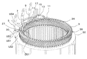
- FIG. 2 is a perspective view showing a configuration of a stator used in the rotating electrical machine according to the embodiment of the present invention.
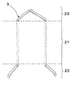
- FIG. 3 is a front view showing the configuration of the U-shaped segment conductor used in the stator of the rotating electrical machine according to the embodiment of the present invention.
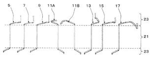
- FIG. 4 is a front view showing the configuration of the deformed segment conductor used in the stator of the rotating electrical machine according to the embodiment of the present invention.
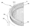
- FIG. 5 is a partially enlarged perspective view showing the configuration of the stator used in the rotating electrical machine according to the embodiment of the present invention.
- FIG. 6 is a cross-sectional view showing the main configuration of the stator used in the rotating electrical machine according to the embodiment of the present invention.
- symbol as FIG. 1 has shown the same part.
- the stator 30 measures the temperature of a stator core 32 having a plurality of slots formed in the circumferential direction, a stator winding 34 composed of segment conductors, and the stator winding 34.
- a thermistor 38 is provided.
- the temperature measuring element unit 1 of the thermistor 38 is accommodated in a minute gap of the stator coil end 36 of the stator winding 34.
- the stator winding 34 connects the U-shaped segment conductor 3 having a substantially U-shape and the odd-shaped segment conductors 5, 7, 9, 11, 13, 15, 17 having a different shape from the U-shaped segment conductor. Configured.
- the U-shaped segment conductor 3 includes a slot portion 21 housed in two slots apart from the stator core 32 shown in FIG. 2, and a connection for connecting them at the end of the slot portion. It consists of the part 23, and has a substantially U shape.
- the odd-shaped segment conductors 5, 7, 9, 11A, 11B, 13, 15, and 17 are slot portions 21 that are accommodated in two slots apart from the stator core 32 shown in FIG. And a connecting portion 23 connected from the end of the slot to a UVW lead terminal, a neutral point, and a crossover portion.
- the odd-shaped segment conductors 5, 7, 9, 11A, 11B, 13, 15, and 17 are different in shape from the U-shaped segment conductor, and are crank-shaped segment conductors as shown in the figure.
- the deformed segment conductor 11A and the deformed segment conductor 11B are connected at the upper end of the figure and used as the deformed segment conductor 11 shown in FIG. Therefore, like the deformed segment conductor 11A and the deformed segment conductor 11B shown in FIG. 4, after configuring as two members, the end portions may be connected or configured as one member having a shape in which both are connected in advance. Is also good.
- the U-shaped segment conductor 3 and the deformed segment conductors 5, 7, 9, 11, 13, 15, 17 are arranged in the slots of the plurality of stator cores 32.
- the connection portion 23 of the U-shaped segment conductor 3 and the connection portion 23 of the deformed segment conductors 5, 7, 9, 11, 13, 15, 17 are arranged at the end of the stator core 32, and the stator coil end 36 is formed.
- the stator of the rotating electrical machine shown in FIG. 2 is a three-phase one.
- the stator windings are star-connected.
- the stator winding of each phase consists of two windings, and both are connected in series.
- a gap 27 is always present between the U-shaped segment conductor 3 and the deformed segment conductor 11 in the stator coil end 36.
- the gap 27 is not only between the U-shaped segment conductor 3 and the deformed segment conductor 11, but also between the U-shaped segment conductor 3 and the deformed segment conductor 5, between the U-shaped segment conductor 3 and the deformed segment conductor 7, Between the U-shaped segment conductor 3 and the deformed segment conductor 9, between the U-shaped segment conductor 3 and the deformed segment conductor 13, between the U-shaped segment conductor 3 and the deformed segment conductor 15, or between the U-shaped segment conductor 3 and the deformed segment conductor. It also exists between the conductors 17.
- the temperature measuring element portion 1 of the thermistor is inserted into the stator coil end 36 through a gap 27 formed between the adjacent U-shaped segment conductor 3 and the deformed segment conductor 11, and is fixed as shown in FIG. It is stored in a minute gap sandwiched between the connection portions 23 of the U-shaped segment conductor 3 and the deformed segment conductor 11 of the child coil end 36.
- FIG. 6 shows a cross-sectional view of the thermistor at the temperature measuring element portion 1.
- the temperature measuring element unit 1 has a cylindrical shape.
- FIG. 6A is a cross-sectional view of the surface of the temperature measuring element portion 1 that is perpendicular to the cylindrical central axis.
- FIG. 6B is a cross-sectional view of a surface including the central axis of the cylindrical shape of the temperature measuring element unit 1.
- the segment conductor indicated by the symbol DS1 is the deformed segment conductor 11 shown in FIG. 5, and the correspondence between FIGS. 5 and 6 is clearly shown by adding the symbol DS1 to FIG.
- Reference numerals US1, US2, US3, and US4 are U-shaped segment conductors 3 shown in FIG. 5, respectively, and reference numerals US1, US2, US3, and US4 are added to FIG. Is specified.
- the temperature measuring element portion 1 of the thermistor is housed in a minute gap sandwiched between adjacent U-shaped segment conductors 3 and deformed segment conductors 11. .
- the temperature measuring element portion 1 of the thermistor is inserted from a gap 27 formed between the U-shaped segment conductor 3 and the deformed segment conductor 11 connected to the crossing. 36 may be inserted through a gap 27 formed between the U-shaped segment conductor 3 and the odd-shaped segment conductors 5, 7, 9, 13, 15, 17.
- the temperature measuring element of the thermistor is completely embedded in the stator coil end. Therefore, the temperature measuring element is surrounded by the stator winding that generates heat, and the temperature detection accuracy of the thermistor and the actual stator The followability to the winding temperature can be improved.
- the temperature measuring element portion of the thermistor is stably sandwiched from the rigid stator winding. Therefore, the position of the temperature measurement element part of the thermistor is stable and the contact state with the appropriate stator winding is obtained, so that temperature detection variation does not easily occur in each stator, and the temperature measurement element part of the thermistor is inserted. After that, there is no need to fix with lacing yarn or adhesive. Therefore, the temperature measuring element portion of the thermistor can be accurately and stably attached to the stator.
- the gap formed between the U-shaped segment conductor into which the temperature measuring element portion of the thermistor is inserted and the deformed segment conductor has a large stator winding diameter or a flat wire. Therefore, since the gap is relatively large and the position is stable, the temperature measuring element portion 1 of the thermistor can be automatically inserted by equipment, or the workability can be improved by manual insertion.
- the thermistor can be attached to the stator winding with high reliability.
- the temperature detection accuracy of the thermistor can be improved, and the followability to a sudden change in the stator winding temperature can be improved.
- the temperature measuring element part of the thermistor can be attached to the stator accurately and stably.
- the mounting operation can be automated or improved, and the thermistor can be mounted with high reliability.
- the overall configuration of the rotating electrical machine according to the present embodiment is the same as that shown in FIG. Moreover, the structure of the stator used for the rotary electric machine by this embodiment is the same as that of what was shown in FIG.
- FIG. 7 is a partially enlarged perspective view showing a configuration of a stator used in a rotating electrical machine according to another embodiment of the present invention.
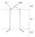
- FIG. 8 is a front view showing a configuration of a U-shaped segment conductor used in a stator of a rotating electrical machine according to another embodiment of the present invention.
- the U-shaped segment conductor 3 and the modified U-shaped segment conductor 19 are arranged in the slots of the plurality of stator cores 32, thereby connecting the U-shaped segment conductor 3 and the modified U-shaped segment conductor.
- a stator coil end 36 is formed, in which 19 deformed connection portions are arranged at the end of the stator core 32.
- the temperature measuring element portion 1 of the thermistor is inserted into the stator coil end 36 through a gap formed between the adjacent U-shaped segment conductor 3 and the deformed U-shaped segment conductor 19. As a result, the temperature measuring element portion 1 of the thermistor is accommodated between the minute gaps sandwiched between the connecting portion 23 of the U-shaped segment conductor 3 of the stator coil end 36 and the deformed connecting portion 25 of the deformed U-shaped segment conductor 19. ing.
- the modified U-shaped segment conductor 19 includes a slot portion 21 accommodated in two slots apart from the stator core 32 and a connection portion 23 for connecting them at the end of the slot portion.
- the connection part of the upper side of the U-shaped segment conductor 3 is a different shape, and consists of the deformed connection part 25 which has the convex part 19A.
- the temperature measuring element of the thermistor is completely embedded in the stator coil end. Therefore, the temperature measuring element is surrounded by the stator winding that generates heat, and the temperature detection accuracy of the thermistor and the actual stator The followability to the winding temperature can be improved.
- the temperature measuring element portion of the thermistor is stable because of the highly rigid stator winding. Since the position of the thermistor's temperature measurement element is stable and the contact state with the appropriate stator winding is obtained, the temperature detection variation of each stator is less likely to occur, and thermistor temperature measurement After the element portion is inserted, there is no need to fix it with a lacing thread or an adhesive. Therefore, the temperature measuring element portion of the thermistor can be accurately and stably attached to the stator.
- the gap formed between the U-shaped segment conductor into which the temperature measuring element portion of the thermistor is inserted and the deformed segment conductor has a large stator winding diameter or a flat wire. Therefore, since the gap becomes relatively large and the position is stable, the temperature measuring element portion of the thermistor can be automatically inserted by equipment, or the workability can be improved by manual insertion.
- the temperature detection accuracy of the thermistor can be improved, and the followability to a sudden change in the stator winding temperature can be improved.
- the temperature measuring element part of the thermistor can be attached to the stator accurately and stably.
- the mounting operation can be automated or improved, and the thermistor can be mounted with high reliability.
- the temperature measuring element portion 1 of the thermistor shown in FIGS. 5 and 7 is housed in a minute gap sandwiched between the segment conductor connecting portions of the stator coil end.
- the temperature measuring element unit 1 is fixed with a varnish.
- the temperature measuring element portion of the thermistor is completely embedded in the stator coil end, so that the temperature measuring element portion is surrounded from all sides by the stator winding that generates heat, and the stator winding by the varnish. Since the heat transfer from the wire is improved, the temperature detection accuracy of the thermistor and the followability to the actual stator winding temperature can be improved.
Landscapes
- Engineering & Computer Science (AREA)
- Power Engineering (AREA)
- Microelectronics & Electronic Packaging (AREA)
- Windings For Motors And Generators (AREA)
Abstract
サーミスタの温度検出精度が向上し、また、固定子巻線温度の急激な変化に対する追従性を向上した回転電機を提供することにある。 回転電機100は、軸支された回転軸上に構成された回転子50と、回転子の外周に微小隙間を介して配置された固定子30とを有する。固定子30は、周方向に複数形成されたスロットを有した固定子コア32と、固定子コアのスロットに挿入される複数のセグメント導体を接続した固定子巻線34と、固定子巻線の温度を測定するサーミスタ38とを有する。固定子巻線34は、スロット内に収納されるスロット部21と、スロット部の端部を連結する接続部23とからなる。サーミスタ38の温度測定素子部1は、固定子コイルエンドの、セグメント導体の接続部同士に挟まれた微小隙間27の間に収められている。
Description
本発明は、回転電機に係り、特に、固定子巻線の温度を測定するのに好適な回転電機に関する。
回転電機の固定子巻線の温度を測定するサーミスタの取り付け方として、例えば、特許文献1に記載のものが知られている。特許文献1は、環状のステータコアと、ステータコアに形成された複数のスロット部と、矩形断面を有し、複数のスロット部に予め定められた巻回方法に従って巻回されてコイル部を形成する複数の平角線材と、複数の平角線材がステータコアの軸方向端面に突き出す部分であるコイルエンド部であって、複数の平角線材がその矩形断面の平面の1つをステータコア端面に平行として、ステータステータコアの周方向に沿って相互に平行に配置されて配置されるコイルエンド部と、コイルエンド部に配置される温度センサと、を備え、コイルエンド部は、ステータコアの周方向に沿って相互に平行に配置される複数の平角線材のうち、ステータコアの径方向に互いに離間間隔を開けて配置される2本の平角線材を、離間間隔の間に配置される他の平角線材に比べ、コイルエンドの軸方向にさらに突き出させて、形成される平行な離間壁空間を有し、温度センサは、コイルエンドの離間壁空間に収納されて配置されることを特徴とする回転電機を開示している。
サーミスタの温度測定素子部は、固定子巻線の固定子コイルエンドにおける固定子巻線同士の隙間に収められるのが一般的である。
しかし、サーミスタの温度測定素子部は機械的強度が低いため、チューブや樹脂により保護されているのが一般的である。また、昨今の地球温暖化という問題を回避するために開発が盛んに行われているハイブリッドカーにおいて、車両を駆動する回転電機がトランスミッション内に搭載される場合がる。この場合、回転電機はオートマチックトランスミッションフルード(ATF)に晒されることとなるため、耐油性を確保する上でも、サーミスタの温度測定素子部は何らかの保護部材に覆われていることが多い。
よって、サーミスタの温度測定素子部はある程度の寸法を持っており、固定子巻線同士の隙間に収めるのは容易ではない。
また、分布巻き固定子巻線で構成される固定子においては、固定子巻線の線径が細いため固定子コイルエンドの剛性が低く、サーミスタの温度測定素子部を巻線内に挿入するための隙間を形成することができた。しかし、セグメント導体の固定子巻線で構成される固定子では、固定子巻線の線径が太かったり、平角線であったりすることが一般的である。そのため、固定子コイルエンド及びそれを構成する固定子巻線の剛性が高く、サーミスタの温度測定素子部を挿入するための隙間を形成することができない。
これらのことから、セグメント導体固定子巻線で構成される固定子では、サーミスタの温度測定素子部は、固定子コイルエンド表面の固定子巻線に這わせて設置し、レーシング糸や接着剤により固定するのが一般的である。この取り付け方法は、サーミスタの温度測定素子部が発熱する固定子巻線に完全に囲まれないため、サーミスタの温度検出精度が悪く、固定子巻線温度の急激な変化に対する追従性も悪くなる可能性がある。また、サーミスタの温度測定素子部と固定子巻線の接触状態のばらつきにより、固定子個々の温度検出ばらつきが大きくなることが懸念される。
また、特許文献1の取り付け方においても、サーミスタの温度測定素子部は、固定子巻線の固定子コイルエンド表面に這わせて設置している。そのため、サーミスタの温度測定素子部の三方が固定子巻線に囲まれているものの、一方が固定子巻線の外部にむき出しとなっており、サーミスタの温度検出精度や、固定子巻線温度の急激な変化に対する追従性も良くないことが予想される。そして、サーミスタの温度測定素子部を固定子コイルエンドに設置した後は、レーシング糸や接着剤により固定しなくてはならないことが想像される。
すなわち、これらの従来のサーミスタ取り付け方法では、サーミスタの温度検出精度や、固定子巻線温度の急激な変化に対する追従性が悪く、固定子個々における検出温度のばらつきが発生しやすい問題がある。
本発明の目的は、サーミスタの温度検出精度が向上し、また、固定子巻線温度の急激な変化に対する追従性を向上した回転電機を提供することにある。
上記目的を達成するために、本発明は、軸支された回転軸上に構成された回転子と、該回転子の外周に微小隙間を介して配置された固定子とを有し、該固定子は、周方向に複数形成されたスロットを有した固定子コアと、該固定子コアのスロットに挿入される複数のセグメント導体を接続した固定子巻線と、該固定子巻線の温度を測定するサーミスタとを有し、前記固定子巻線は、前記スロット内に収納されるスロット部と、前記スロット部の端部を連結する接続部とからなる回転電機であって、前記サーミスタの温度測定素子部は、前記セグメント導体を複数前記固定子コアのスロットに配列することにより、前記セグメント導体の接続部が前記固定子コア端部に配列されて形成される固定子コイルエンドの、前記セグメント導体の接続部同士に挟まれた微小隙間の間に収められているものである。
かかる構成により、サーミスタの温度検出精度が向上し、また、固定子巻線温度の急激な変化に対する追従性を向上し得るものとなる。
本発明によれば、サーミスタの温度検出精度が向上し、また、固定子巻線温度の急激な変化に対する追従性を向上し得るものとなる。
以下、図1~図6を用いて、本発明の一実施形態による回転電機の構成について説明する。
最初に、図1を用いて、本実施形態による回転電機の全体構成について説明する。
図1は、本発明の一実施形態による回転電機の全体構成を示す断面図である。
最初に、図1を用いて、本実施形態による回転電機の全体構成について説明する。
図1は、本発明の一実施形態による回転電機の全体構成を示す断面図である。
回転電機100は、軸受け52により軸支された回転軸上に構成された回転子50と、回転子50の外周に微小隙間を介して配置された固定子30を備えている。2個の軸受け52の内一方は、フロントブラケットFBに取り付けられ、他方はリアブラケットRBに取り付けられている。フロントブラケットFBは、円筒状のハウジングHSの一方の開放端に固定され、リアブラケットRBは、ハウジングHSの他方の開放端に固定されている。固定子30は、ハウジングHSの内周側に固定されている。
固定子30は、周方向に複数形成されたスロットを有した固定子コア32と、セグメント導体からなる固定子巻線34と、固定子巻線34の温度を測定するサーミスタ38を備えている。サーミスタ38の温度測定素子部1は、固定子巻線34の固定子コイルエンド36に、取り付けられている。
次に、図2~図6を用いて、本実施形態による回転電機に用いる固定子の構成について説明する。
図2は、本発明の一実施形態による回転電機に用いる固定子の構成を示す斜視図である。図3は、本発明の一実施形態による回転電機の固定子に用いるU字セグメント導体の構成を示す正面図である。図4は、本発明の一実施形態による回転電機の固定子に用いる異形セグメント導体の構成を示す正面図である。図5は、本発明の一実施形態による回転電機に用いる固定子の構成を示す部分拡大斜視図である。図6は、本発明の一実施形態による回転電機に用いる固定子の要部構成を示す断面図である。なお、各図において、図1と同一符号は、同一部分を示している。
図2は、本発明の一実施形態による回転電機に用いる固定子の構成を示す斜視図である。図3は、本発明の一実施形態による回転電機の固定子に用いるU字セグメント導体の構成を示す正面図である。図4は、本発明の一実施形態による回転電機の固定子に用いる異形セグメント導体の構成を示す正面図である。図5は、本発明の一実施形態による回転電機に用いる固定子の構成を示す部分拡大斜視図である。図6は、本発明の一実施形態による回転電機に用いる固定子の要部構成を示す断面図である。なお、各図において、図1と同一符号は、同一部分を示している。
図2に示すように、固定子30は、周方向に複数形成されたスロットを有した固定子コア32と、セグメント導体からなる固定子巻線34と、固定子巻線34の温度を測定するサーミスタ38を備えている。サーミスタ38の温度測定素子部1は、固定子巻線34の固定子コイルエンド36の微小隙間の間に収められている。
固定子巻線34は、概略U字の形状をしたU字セグメント導体3と、U字セグメント導体とは形状の異なる異形セグメント導体5,7,9,11,13,15,17と、を接続して構成される。
図3に示すように、U字セグメント導体3は、図2に示した固定子コア32の離れた2つのスロット内に収納されるスロット部21と、それらをスロット部の端部で連結する接続部23からなり、概略U字の形状をしている。
図4に示すように、異形セグメント導体5,7,9,11A,11B,13,15,17は、図2に示した固定子コア32の離れた2つのスロット内に収納されるスロット部21と、スロットの端部からUVW口出し端子や中性点や渡り部に連結される接続部23からなる。そして、異形セグメント導体5,7,9,11A,11B,13,15,17は、U字セグメント導体とは形状の異なるものであり、図示のように、クランク形状のセグメント導体である。
異形セグメント導体11Aと異形セグメント導体11Bとは、図示の上方の端部で接続され、図2に示した異形セグメント導体11として用いられる。従って、図4に示す異形セグメント導体11Aと異形セグメント導体11Bのように、2部材として構成した後、端部を接続しても良いし、両者が予め接続された形状の1部材として構成しても良いものである。
そして、本実施形態においては、図2に示すように、U字セグメント導体3と異形セグメント導体5,7,9,11,13,15,17を複数固定子コア32のスロットに配列することにより、U字セグメント導体3の接続部23と、異形セグメント導体5,7,9,11,13,15,17の接続部23とが、固定子コア32の端部に配列されて固定子コイルエンド36が形成される。
図2に示す回転電機の固定子は、3相のものである。固定子巻線はスター結線されている。また、各相の固定子巻線は2つの巻線からなり、両者は直列接続されている。
そして、図2に示す固定子コア32が72個のスロットを備えている場合、図3に示したU字セグメント導体3は、72個用いられる。図4に示した異形セグメント導体5,7,9は、3相のUVW口出し端子として用いられるため、それぞれ、1個づつ用いられる。異形セグメント導体11となる、異形セグメント導体11A,11Bは、各相毎の2直列構成とするための渡り部として用いられるため、それぞれ、3個づつ用いられる。異形セグメント導体13,15,17は、中性点として用いられるため、それぞれ1個づつ用いられる。
図5に示すように、固定子コイルエンド36において、U字セグメント導体3と異形セグメント導体11の間には、隙間27がかならず存在する。なお、隙間27は、U字セグメント導体3と異形セグメント導体11の間だけでなく、U字セグメント導体3と異形セグメント導体5の間や、U字セグメント導体3と異形セグメント導体7の間や、U字セグメント導体3と異形セグメント導体9の間や、U字セグメント導体3と異形セグメント導体13の間や、U字セグメント導体3と異形セグメント導体15の間や、U字セグメント導体3と異形セグメント導体17の間にも存在する。
サーミスタの温度測定素子部1は、隣り合ったU字セグメント導体3と、異形セグメント導体11の間に形成される隙間27から固定子コイルエンド36内に挿入され、図2に示すように、固定子コイルエンド36のU字セグメント導体3や異形セグメント導体11の接続部23同士に挟まれた微小隙間の間に収められている。
図6は、サーミスタの温度測定素子部1の位置における断面図を示している。温度測定素子部1は円柱形状である。そして、図6(A)は、温度測定素子部1の円柱形状の中心軸に直交する面における断面図である。図6(B)は、温度測定素子部1の円柱形状の中心軸を含む面における断面図である。
符号DS1で示されるセグメント導体は、図5に示した異形セグメント導体11であり、図5に符号DS1を付して図5と図6の対応関係を明示している。また、符号US1,US2,US3,US4は、それぞれ、図5に示したU字セグメント導体3であり、図5に符号US1,US2,US3,US4を付して図5と図6の対応関係を明示している。
図6(A)(B)から理解されるように、サーミスタの温度測定素子部1は、隣り合ったU字セグメント導体3や異形セグメント導体11に挟まれた微小隙間の間に収められている。
従来の特許文献1記載のものでは、温度測定素子部の三方が固定子巻線に囲まれているが、一方が固定子巻線の外部にむき出しとなっている。それに対して本実施形態のものでは、四方が固定子巻線に囲まれた状態として温度測定素子部1が配置されるため、サーミスタの温度検出精度が向上し、固定子巻線温度の急激な変化に対する追従性も良くなる。
図2では、U字セグメント導体3と、渡りへ接続される異形セグメント導体11の間に形成される隙間27からサーミスタの温度測定素子部1を挿入しているが、それ以外の固定子コイルエンド36における、U字セグメント導体3と異形セグメント導体5,7,9,13,15,17の間に形成される隙間27から挿入してもよいものである。
サーミスタの温度測定素子部が、固定子コイルエンド内に完全に埋め込まれるため、温度測定素子部が発熱する固定子巻線に四方から囲まれることになり、サーミスタの温度検出精度及び実際の固定子巻線温度への追従性を向上させることができる。
また、U字セグメント導体と、異形セグメント導体の間に形成される隙間から固定子コイルエンド内に挿入されるため、サーミスタの温度測定素子部は剛性の高い固定子巻線から安定的に挟まれるため、サーミスタの温度測定素子部の位置が安定し、かつ適切な固定子巻線との接触状態が得られるため、固定子個々に温度検出ばらつきが発生しにくく、またサーミスタの温度測定素子部挿入後は、レーシング糸や接着剤により固定する必要はない。従って、サーミスタの温度測定素子部を固定子へ正確に、かつ安定的に取り付けることができる。
サーミスタの温度測定素子部を挿入するU字セグメント導体と、異形セグメント導体の間に形成される隙間は、固定子巻線の線径が太かったり、平角線であったりすることが一般的であるため、比較的大きな隙間となり、また位置も安定することから、サーミスタの温度測定素子部1を設備により自動で挿入させたり、また手作業による挿入でも作業性を向上させることができる。
これらのことから、固定子巻線へ高い信頼性でサーミスタを取り付けられることができるのである。
本実施形態によれば、サーミスタの温度検出精度が向上し、また、固定子巻線温度の急激な変化に対する追従性を向上することができる。
また、サーミスタの温度測定素子部を固定子へ正確に、かつ安定的に取り付けることができる。
さらに、取り付け作業の自動化または作業性を向上でき、高い信頼性でサーミスタを取り付けられるものとなる。
次に、図7及び図8を用いて、本発明の他の実施形態による回転電機の構成について説明する。なお、本実施形態による回転電機の全体構成は、図1に示したものと同様である。また、本実施形態による回転電機に用いる固定子の構成は、図2に示したものと同様である。
図7は、本発明の他の実施形態による回転電機に用いる固定子の構成を示す部分拡大斜視図である。図8は、本発明の他の実施形態による回転電機の固定子に用いるU字セグメント導体の構成を示す正面図である。
図5に示した例では、72個のU字セグメント導体3を用いていた。それに対して、本実施形態では、71個のU字セグメント導体3と、図8で詳述する1個の異形U字セグメント導体19を用いている。なお、図3に示した異形セグメント導体3,5,7,9,11,13,15,17は、第1の実施形態と同様に用いる。
図7に示すように、U字セグメント導体3と異形U字セグメント導体19とを、複数固定子コア32のスロットに配列することにより、U字セグメント導体3の接続部と、異形U字セグメント導体19の異形接続部とが、固定子コア32端部に配列されて形成される固定子コイルエンド36が構成される。
サーミスタの温度測定素子部1は、隣り合ったU字セグメント導体3と、異形U字セグメント導体19の間に形成される隙間から固定子コイルエンド36内に挿入される。これにより、サーミスタの温度測定素子部1は、固定子コイルエンド36のU字セグメント導体3の接続部23や異形U字セグメント導体19の異形接続部25に挟まれた微小隙間の間に収められている。
図8に示すように、異形U字セグメント導体19は、固定子コア32の離れた2つのスロット内に収納されるスロット部21と、それらをスロット部の端部で連結するための接続部23と、U字セグメント導体3の上側の接続部は異なる形状であり、凸部19Aを有する異形接続部25とからなる。
サーミスタの温度測定素子部が、固定子コイルエンド内に完全に埋め込まれるため、温度測定素子部が発熱する固定子巻線に四方から囲まれることになり、サーミスタの温度検出精度及び実際の固定子巻線温度への追従性を向上させることができる。
また、U字セグメント導体と、異形U字セグメント導体の間に形成される隙間から固定子コイルエンド内に挿入されるため、サーミスタの温度測定素子部は剛性の高い固定子巻線のから安定的に挟まれるため、サーミスタの温度測定素子部の位置が安定し、かつ適切な固定子巻線との接触状態が得られるため、固定子個々に温度検出ばらつきが発生しにくく、またサーミスタの温度測定素子部挿入後は、レーシング糸や接着剤により固定する必要はない。従って、サーミスタの温度測定素子部を固定子へ正確に、かつ安定的に取り付けることができる。
サーミスタの温度測定素子部を挿入するU字セグメント導体と、異形セグメント導体の間に形成される隙間は、固定子巻線の線径が太かったり、平角線であったりすることが一般的であるため、比較的大きな隙間となり、また位置も安定することから、サーミスタの温度測定素子部を設備により自動で挿入させたり、また手作業による挿入でも作業性を向上させることができる。
本実施形態によれば、サーミスタの温度検出精度が向上し、また、固定子巻線温度の急激な変化に対する追従性を向上することができる。
また、サーミスタの温度測定素子部を固定子へ正確に、かつ安定的に取り付けることができる。
さらに、取り付け作業の自動化または作業性を向上でき、高い信頼性でサーミスタを取り付けられるものとなる。
なお、図5及び図7に示したサーミスタの温度測定素子部1は、固定子コイルエンドの、セグメント導体の接続部同士に挟まれた微小隙間の間に収められている。その上で、温度測定素子部1は、ワニスにより固定されている。これにより、サーミスタの温度測定素子部が、固定子コイルエンド内に完全に埋め込まれるため、温度測定素子部が発熱する固定子巻線に四方から囲まれることになり、かつ、ワニスにより固定子巻線からの熱伝達が良くなるため、サーミスタの温度検出精度及び実際の固定子巻線温度への追従性を向上させることができる。
1…サーミスタ温度測定素子部
3…U字セグメント導体
5…異形セグメント導体(U相口出し)
7…異形セグメント導体(V相口出し)
9…異形セグメント導体(W相口出し)
11…異形セグメント導体(渡り)
13…異形セグメント導体(U相中性点)
15…異形セグメント導体(V相中性点)
17…異形セグメント導体(W相中性点)
19…異形U字セグメント導体
21…セグメント導体スロット部
23…セグメント導体接続部
25…セグメント導体異形接続部
27…サーミスタ温度測定素子部挿入隙間
30…固定子
32…固定子コア
34…固定子巻線
36…固定子コイルエンド
38…サーミスタ
50…回転子
52…軸受け
100…回転電機
3…U字セグメント導体
5…異形セグメント導体(U相口出し)
7…異形セグメント導体(V相口出し)
9…異形セグメント導体(W相口出し)
11…異形セグメント導体(渡り)
13…異形セグメント導体(U相中性点)
15…異形セグメント導体(V相中性点)
17…異形セグメント導体(W相中性点)
19…異形U字セグメント導体
21…セグメント導体スロット部
23…セグメント導体接続部
25…セグメント導体異形接続部
27…サーミスタ温度測定素子部挿入隙間
30…固定子
32…固定子コア
34…固定子巻線
36…固定子コイルエンド
38…サーミスタ
50…回転子
52…軸受け
100…回転電機
Claims (4)
- 軸支された回転軸上に構成された回転子と、該回転子の外周に微小隙間を介して配置された固定子とを有し、
該固定子は、周方向に複数形成されたスロットを有した固定子コアと、該固定子コアのスロットに挿入される複数のセグメント導体を接続した固定子巻線と、該固定子巻線の温度を測定するサーミスタとを有し、
前記固定子巻線は、前記スロット内に収納されるスロット部と、前記スロット部の端部を連結する接続部とからなる回転電機であって、
前記サーミスタの温度測定素子部は、前記セグメント導体を複数前記固定子コアのスロットに配列することにより、前記セグメント導体の接続部が前記固定子コア端部に配列されて形成される固定子コイルエンドの、前記セグメント導体の接続部同士に挟まれた微小隙間の間に収められていることを特徴とする回転電機。 - 請求項1記載の回転電機において、
前記セグメント導体は、
前記固定子コアの離れた2つのスロット内に収納されるスロット部と、それらを前記スロット部の端部で連結する接続部からなる概略U字の形状をしたU字セグメント導体と、 前記スロット内に収納されるスロット部と、スロット部の端部からUVW口出し端子や中性点や渡り部に連結される接続部からなり、前記U字セグメント導体とは形状の異なる異形セグメント導体と、からなり、
前記U字セグメント導体と前記異形セグメント導体とを、複数前記固定子コアのスロットに配列することにより、前記U字セグメント導体の接続部と前記異形セグメント導体の接続部とが、前記固定子コア端部に配列されて形成される固定子コイルエンドを形成し、 前記サーミスタの温度測定素子部は、隣り合った前記U字セグメント導体と、前記異形セグメント導体の間に形成される隙間から前記固定子コイルエンド内に挿入され、前記固定子コイルエンドの前記U字セグメント導体や前記異形セグメント導体の接続部同士に挟まれた微小隙間の間に収められていることを特徴とする回転電機。 - 請求項1記載の回転電機において、
前記セグメント導体は、
前記固定子コアの離れた2つのスロット内に収納されるスロット部と、それらを前記スロット部の端部で連結する接続部からなる概略U字の形状をしたU字セグメント導体と、 前記固定子コアの離れた2つのスロット内に収納されるスロット部と、それらを前期スロット部の端部で連結し、前記U字セグメント導体の接続部とは異なる凸状の形状をした異形接続部からなる異形U字セグメント導体と、からなり、
前記U字セグメント導体と前記異形U字セグメント導体とを、複数前記固定子コアのスロットに配列することにより、前記U字セグメント導体の接続部と、前記異形U字セグメント導体の異形接続部とが、前記固定子コア端部に配列されて固定子コイルエンドを形成し、
前記サーミスタの温度測定素子部は、隣り合った前記U字セグメント導体と、前記異形U字セグメント導体の間に形成される隙間から前記固定子コイルエンド内に挿入され、前記固定子コイルエンドの前記U字セグメント導体や前記異形U字セグメント導体の接続部または異形接続部同士に挟まれた微小隙間の間に収められていることを特徴とする回転電機。 - 請求項2若しくは請求項3のいずれかに記載の回転電機において、
前記サーミスタの温度測定素子部は、ワニスにより前記セグメント導体の接続部同士に挟まれた微小隙間の間に固定されていることを特徴とする回転電機。
Priority Applications (1)
| Application Number | Priority Date | Filing Date | Title |
|---|---|---|---|
| US14/439,109 US9735659B2 (en) | 2012-10-29 | 2013-10-09 | Electric rotating machine having a thermistor in a gap between U-shaped and odd-shaped coil ends |
Applications Claiming Priority (2)
| Application Number | Priority Date | Filing Date | Title |
|---|---|---|---|
| JP2012238132A JP6022896B2 (ja) | 2012-10-29 | 2012-10-29 | 回転電機 |
| JP2012-238132 | 2012-10-29 |
Publications (1)
| Publication Number | Publication Date |
|---|---|
| WO2014069191A1 true WO2014069191A1 (ja) | 2014-05-08 |
Family
ID=50627105
Family Applications (1)
| Application Number | Title | Priority Date | Filing Date |
|---|---|---|---|
| PCT/JP2013/077408 Ceased WO2014069191A1 (ja) | 2012-10-29 | 2013-10-09 | 回転電機 |
Country Status (3)
| Country | Link |
|---|---|
| US (1) | US9735659B2 (ja) |
| JP (1) | JP6022896B2 (ja) |
| WO (1) | WO2014069191A1 (ja) |
Cited By (1)
| Publication number | Priority date | Publication date | Assignee | Title |
|---|---|---|---|---|
| JP2022170392A (ja) * | 2021-04-28 | 2022-11-10 | 澤藤電機株式会社 | ステータおよびそのステータを備えた回転電機 |
Families Citing this family (26)
| Publication number | Priority date | Publication date | Assignee | Title |
|---|---|---|---|---|
| JP6137552B2 (ja) * | 2014-07-08 | 2017-05-31 | 株式会社デンソー | 回転電機 |
| JP6405775B2 (ja) * | 2014-08-07 | 2018-10-17 | 株式会社デンソー | ダブルステータ型回転電機 |
| CN108473197B (zh) * | 2015-12-31 | 2022-10-28 | 日本电产株式会社 | 多旋翼机 |
| FR3046506B1 (fr) * | 2016-01-05 | 2019-06-21 | Valeo Equipements Electriques Moteur | Stator pour une machine electrique tournante |
| JP6725296B2 (ja) * | 2016-03-31 | 2020-07-15 | 株式会社小松製作所 | ステータ |
| JP6692674B2 (ja) | 2016-03-31 | 2020-05-13 | 株式会社小松製作所 | ステータ |
| WO2017217271A1 (ja) * | 2016-06-16 | 2017-12-21 | 三菱電機株式会社 | 回転電機の固定子 |
| JP6799962B2 (ja) * | 2016-08-03 | 2020-12-16 | 本田技研工業株式会社 | バスバーユニット |
| US11374468B2 (en) * | 2017-11-15 | 2022-06-28 | Hitachi Astemo, Ltd. | Rotating electric machine |
| JP2019205260A (ja) * | 2018-05-22 | 2019-11-28 | 本田技研工業株式会社 | ステータおよび回転電機 |
| US10965196B2 (en) | 2018-08-06 | 2021-03-30 | Ford Global Technologies, Llc | Electric machine thermal management |
| US10923991B2 (en) | 2018-08-06 | 2021-02-16 | Ford Global Technologies, Llc | Electric machine thermal management |
| US10931176B2 (en) | 2018-08-06 | 2021-02-23 | Ford Global Technologies, Llc | Electric machine thermal management |
| JP2020072576A (ja) * | 2018-10-31 | 2020-05-07 | 株式会社小松製作所 | 回転電機ステータ |
| DE102019204002A1 (de) * | 2019-03-25 | 2020-10-01 | Audi Ag | Verfahren zum Herstellen eines Bauteils |
| WO2020240762A1 (ja) * | 2019-05-30 | 2020-12-03 | 日立オートモティブ電動機システムズ株式会社 | 回転電機 |
| DE102019134785A1 (de) * | 2019-12-17 | 2021-06-17 | Grob-Werke Gmbh & Co. Kg | Vorrichtung und Verfahren zum Biegen von Draht für ein Maschinenelement einer elektrischen Maschine |
| US11309761B2 (en) | 2020-03-24 | 2022-04-19 | Ford Global Technologies, Llc | Hairpin winding electric machine |
| US11539255B2 (en) | 2020-03-24 | 2022-12-27 | Ford Global Technologies, Llc | Hairpin winding electric machine |
| US11368066B2 (en) | 2020-04-03 | 2022-06-21 | Ford Global Technologies, Llc | Hairpin winding electric machine |
| DE112021000861T5 (de) | 2020-04-07 | 2022-11-24 | Hitachi Astemo, Ltd. | Stator einer rotierenden elektrischen maschine und rotierende elektrische maschine |
| JP7510786B2 (ja) | 2020-05-15 | 2024-07-04 | 株式会社Subaru | ステータおよびその製造方法 |
| JP7688505B2 (ja) * | 2021-03-31 | 2025-06-04 | 株式会社Subaru | 回転電機 |
| CN115360870A (zh) * | 2022-06-27 | 2022-11-18 | 广州广重企业集团有限公司 | 一种发电机 |
| US20240415278A1 (en) * | 2023-06-14 | 2024-12-19 | Steelcase Inc. | Conference table and components and method for the use thereof |
| US20260155712A1 (en) * | 2024-12-02 | 2026-06-04 | Shilla Industry Co., Ltd. | Stator assembly with improved structure for installing sensor |
Citations (4)
| Publication number | Priority date | Publication date | Assignee | Title |
|---|---|---|---|---|
| JPS63249445A (ja) * | 1987-04-02 | 1988-10-17 | Mitsubishi Electric Corp | 回転電機のサ−マルリレ−取付方法 |
| JPH0670510A (ja) * | 1992-08-12 | 1994-03-11 | Mitsuba Electric Mfg Co Ltd | 電動機のコイルに対する温度センサの埋め込み方法 |
| JP2007089295A (ja) * | 2005-09-21 | 2007-04-05 | Toyota Motor Corp | 回転電機およびレゾルバ |
| JP2011112563A (ja) * | 2009-11-27 | 2011-06-09 | Hitachi Automotive Systems Ltd | 温度センサおよび回転電機 |
Family Cites Families (22)
| Publication number | Priority date | Publication date | Assignee | Title |
|---|---|---|---|---|
| US2471840A (en) * | 1945-09-13 | 1949-05-31 | Gen Electric | Electric protective means |
| US4188553A (en) * | 1978-02-08 | 1980-02-12 | A. O. Smith Corporation | Pocket receptacle for securing a sensing element within electrical windings |
| US4571518A (en) * | 1984-12-12 | 1986-02-18 | Sundstrand Corporation | Temperature sensor pocket for dynamoelectric machine winding |
| US5343613A (en) * | 1993-01-27 | 1994-09-06 | Sundstrand Corporation | Method of installing thermal protection for an electric motor stator |
| JP3419721B2 (ja) * | 1999-12-06 | 2003-06-23 | 三菱電機株式会社 | 車両用交流発電機 |
| FR2819117B1 (fr) * | 2000-12-21 | 2004-10-29 | Valeo Equip Electr Moteur | Alternateur a elements conducteurs en epingle pour vehicule automobile |
| DE10143222C1 (de) * | 2001-09-04 | 2003-04-17 | Siemens Linear Motor Systems G | Temperaturmeßvorrichtung für einen Elektromotor |
| US6787961B2 (en) * | 2002-12-19 | 2004-09-07 | Visteon Global Technologies, Inc. | Automotive alternator stator assembly with varying end loop height between layers |
| JP4046270B2 (ja) * | 2002-05-24 | 2008-02-13 | 三菱電機株式会社 | 回転電機の固定子 |
| FR2840464B1 (fr) * | 2002-05-28 | 2004-09-03 | Valeo Equip Electr Moteur | Alternateur muni d'un stator a entrees vrillees |
| FR2868620B1 (fr) * | 2004-03-31 | 2006-07-21 | Valeo Equip Electr Moteur | Induit polyphase pour machine electrique tournante, notamment un alternateur pour vehicule automobile, et son procede de fabrication |
| JP2006211810A (ja) * | 2005-01-27 | 2006-08-10 | Denso Corp | セグメント連接型回転電機 |
| JP2007043873A (ja) * | 2005-08-05 | 2007-02-15 | Toyota Motor Corp | 回転電機およびそれを搭載した自動車 |
| US20090140596A1 (en) * | 2007-11-30 | 2009-06-04 | Gm Global Technology Operations, Inc. | Methods and apparatus for a bar-wound stator with parallel connections |
| JP5167939B2 (ja) * | 2008-05-12 | 2013-03-21 | 株式会社デンソー | 回転電機のコイル組立体製造方法 |
| CN102027657B (zh) * | 2008-05-16 | 2013-10-16 | 三菱电机株式会社 | 旋转电机 |
| JP4751942B2 (ja) * | 2009-06-17 | 2011-08-17 | アイシン精機株式会社 | ステータ |
| JP2011223673A (ja) * | 2010-04-06 | 2011-11-04 | Toyota Motor Corp | 回転電機 |
| JP5672984B2 (ja) * | 2010-11-04 | 2015-02-18 | アイシン精機株式会社 | 回転電機のステータ |
| JP5516562B2 (ja) * | 2011-02-09 | 2014-06-11 | 株式会社豊田自動織機 | コイル、ステータ、コイルの製造方法 |
| US20130069474A1 (en) * | 2011-09-16 | 2013-03-21 | Remy Technologies, L.L.C. | Composite conductor insulation |
| US20130187494A1 (en) * | 2012-01-25 | 2013-07-25 | Remy Technologies, L.L.C. | Stator assembly for an electric machine |
-
2012
- 2012-10-29 JP JP2012238132A patent/JP6022896B2/ja active Active
-
2013
- 2013-10-09 US US14/439,109 patent/US9735659B2/en active Active
- 2013-10-09 WO PCT/JP2013/077408 patent/WO2014069191A1/ja not_active Ceased
Patent Citations (4)
| Publication number | Priority date | Publication date | Assignee | Title |
|---|---|---|---|---|
| JPS63249445A (ja) * | 1987-04-02 | 1988-10-17 | Mitsubishi Electric Corp | 回転電機のサ−マルリレ−取付方法 |
| JPH0670510A (ja) * | 1992-08-12 | 1994-03-11 | Mitsuba Electric Mfg Co Ltd | 電動機のコイルに対する温度センサの埋め込み方法 |
| JP2007089295A (ja) * | 2005-09-21 | 2007-04-05 | Toyota Motor Corp | 回転電機およびレゾルバ |
| JP2011112563A (ja) * | 2009-11-27 | 2011-06-09 | Hitachi Automotive Systems Ltd | 温度センサおよび回転電機 |
Cited By (2)
| Publication number | Priority date | Publication date | Assignee | Title |
|---|---|---|---|---|
| JP2022170392A (ja) * | 2021-04-28 | 2022-11-10 | 澤藤電機株式会社 | ステータおよびそのステータを備えた回転電機 |
| JP7687853B2 (ja) | 2021-04-28 | 2025-06-03 | 澤藤電機株式会社 | ステータおよびそのステータを備えた回転電機 |
Also Published As
| Publication number | Publication date |
|---|---|
| JP6022896B2 (ja) | 2016-11-09 |
| JP2014090546A (ja) | 2014-05-15 |
| US20150295477A1 (en) | 2015-10-15 |
| US9735659B2 (en) | 2017-08-15 |
Similar Documents
| Publication | Publication Date | Title |
|---|---|---|
| JP6022896B2 (ja) | 回転電機 | |
| JP6070665B2 (ja) | 回転電機ステータ | |
| JP4270307B2 (ja) | 渡り線モジュール | |
| JP6844614B2 (ja) | モータ | |
| JP5789570B2 (ja) | ステータ | |
| CN105830311B (zh) | 旋转电机 | |
| JP6281499B2 (ja) | 回転電機用ステータ | |
| JP2013223293A5 (ja) | ||
| JP2015061465A (ja) | 回転電機ステータ | |
| JP2018061389A (ja) | 回転電機のステータ | |
| JP6443303B2 (ja) | 回転電機ステータ | |
| JP7342654B2 (ja) | 回転電機 | |
| EP3518392B1 (en) | Motor | |
| JP6568473B2 (ja) | ステータ | |
| KR102288301B1 (ko) | 스테이터 및 이를 포함하는 모터 | |
| JP2012244703A (ja) | 電動機のステータ | |
| JP6233217B2 (ja) | 回転電機のステータ | |
| JP5260112B2 (ja) | 回転電機 | |
| JP2016052234A (ja) | リード線付回転電機ステータの製造方法 | |
| JP4875857B2 (ja) | 回転電機 | |
| JP5677503B2 (ja) | 回転電機及び回転電機の製造方法 | |
| JP2014217105A (ja) | 回転電機の固定子および回転電機 | |
| WO2022234824A1 (ja) | 接続コネクタ及び多相モータ | |
| JP7517213B2 (ja) | 回転電機 | |
| JP2009201203A (ja) | 回転電機 |
Legal Events
| Date | Code | Title | Description |
|---|---|---|---|
| 121 | Ep: the epo has been informed by wipo that ep was designated in this application |
Ref document number: 13850526 Country of ref document: EP Kind code of ref document: A1 |
|
| WWE | Wipo information: entry into national phase |
Ref document number: 14439109 Country of ref document: US |
|
| NENP | Non-entry into the national phase |
Ref country code: DE |
|
| 122 | Ep: pct application non-entry in european phase |
Ref document number: 13850526 Country of ref document: EP Kind code of ref document: A1 |