WO2020240762A1 - 回転電機 - Google Patents
回転電機 Download PDFInfo
- Publication number
- WO2020240762A1 WO2020240762A1 PCT/JP2019/021468 JP2019021468W WO2020240762A1 WO 2020240762 A1 WO2020240762 A1 WO 2020240762A1 JP 2019021468 W JP2019021468 W JP 2019021468W WO 2020240762 A1 WO2020240762 A1 WO 2020240762A1
- Authority
- WO
- WIPO (PCT)
- Prior art keywords
- coil
- segment
- slot
- layer
- stator core
- Prior art date
Links
Images


Classifications
-
- H—ELECTRICITY
- H02—GENERATION; CONVERSION OR DISTRIBUTION OF ELECTRIC POWER
- H02K—DYNAMO-ELECTRIC MACHINES
- H02K3/00—Details of windings
- H02K3/04—Windings characterised by the conductor shape, form or construction, e.g. with bar conductors
- H02K3/12—Windings characterised by the conductor shape, form or construction, e.g. with bar conductors arranged in slots
-
- H—ELECTRICITY
- H02—GENERATION; CONVERSION OR DISTRIBUTION OF ELECTRIC POWER
- H02K—DYNAMO-ELECTRIC MACHINES
- H02K3/00—Details of windings
- H02K3/04—Windings characterised by the conductor shape, form or construction, e.g. with bar conductors
- H02K3/24—Windings characterised by the conductor shape, form or construction, e.g. with bar conductors with channels or ducts for cooling medium between the conductors
-
- H—ELECTRICITY
- H02—GENERATION; CONVERSION OR DISTRIBUTION OF ELECTRIC POWER
- H02K—DYNAMO-ELECTRIC MACHINES
- H02K3/00—Details of windings
- H02K3/04—Windings characterised by the conductor shape, form or construction, e.g. with bar conductors
- H02K3/28—Layout of windings or of connections between windings
-
- H—ELECTRICITY
- H02—GENERATION; CONVERSION OR DISTRIBUTION OF ELECTRIC POWER
- H02K—DYNAMO-ELECTRIC MACHINES
- H02K3/00—Details of windings
- H02K3/46—Fastening of windings on the stator or rotor structure
- H02K3/52—Fastening salient pole windings or connections thereto
-
- H—ELECTRICITY
- H02—GENERATION; CONVERSION OR DISTRIBUTION OF ELECTRIC POWER
- H02K—DYNAMO-ELECTRIC MACHINES
- H02K15/00—Methods or apparatus specially adapted for manufacturing, assembling, maintaining or repairing of dynamo-electric machines
- H02K15/04—Methods or apparatus specially adapted for manufacturing, assembling, maintaining or repairing of dynamo-electric machines of windings, prior to mounting into machines
- H02K15/0414—Windings consisting of separate elements, e.g. bars, hairpins, segments, half coils
- H02K15/0421—Windings consisting of separate elements, e.g. bars, hairpins, segments, half coils consisting of single conductors, e.g. hairpins
-
- H—ELECTRICITY
- H02—GENERATION; CONVERSION OR DISTRIBUTION OF ELECTRIC POWER
- H02K—DYNAMO-ELECTRIC MACHINES
- H02K2213/00—Specific aspects, not otherwise provided for and not covered by codes H02K2201/00 - H02K2211/00
- H02K2213/03—Machines characterised by numerical values, ranges, mathematical expressions or similar information
Definitions
- the present invention relates to a rotary electric machine, and particularly relates to a rotary electric machine having a stator core having a plurality of slots and a stator having a plurality of segment coils housed in the slots of the stator core.
- the driving force is obtained by a rotary electric machine.
- the rotary electric machine includes a stator core having a plurality of slots and a plurality of copper cores housed in the slots of the stator core.
- a rotary electric machine having a stator with a segment coil of the above is used.
- a rotary electric machine provided with such a stator is described in, for example, Japanese Patent Application Laid-Open No. 2017-189020 (Patent Document 1).
- the rotary electric machine described in Patent Document 1 includes a stator core having a plurality of axially extending slots on the inner peripheral surface, and a copper segment coil inserted into the slots, and has a stator.
- a parallel portion substantially parallel to the end face portion of the stator core is formed at the top of the bent side (so-called turn portion) of the coil end of the segment coil protruding axially from the end face portion of the core.
- an intermediate inclined portion having an inclination formed by one predetermined angle is formed, and on the other intermediate inclined portion, two different predetermined angles are formed.
- An intermediate inclined portion having a stepped inclination is formed.
- segment coil having such a configuration, it is possible to provide a stator of a rotary electric machine in which the length of the coil end is suppressed while avoiding mechanical interference between adjacent coils at the bending side coil end of the segment coil. Is possible.
- the present invention aims to solve the above-mentioned problems in this type of rotary electric machine.
- an object of the present invention is to provide a novel rotary electric machine capable of suppressing an increase in the length of the coil end on the side where the turn portion is located and improving the cooling performance around the turn portion of the segment coil. is there.
- the feature of the present invention is The segment coil is fixed from one end face of the stator core, a first straight portion inserted into a specific slot, a second straight portion inserted into another specific slot different from the specific slot, and a stator core.
- Each slot has a turn portion extending outward in the axial direction of the child core and having a top connecting a first straight portion and a second straight portion, and each slot is radially from the inner peripheral side.
- the straight portions of the plurality of segment coils are inserted and arranged so as to be laminated on the outer peripheral side, and a bent portion is formed between each straight portion and the turn portion of the segment coils laminated in the radial direction. This bend is where the top of the turn is tilted towards the end face of the stator core.
- the turn portion extending from the end face portion of the stator core is bent outward in the radial direction, so that a sufficient gap is formed between the turn portions of the respective segment coils.
- the cooling performance can be improved by making it easier for the cooling medium to enter the gap or by increasing the substantial contact area between the coil and the cooling medium.
- FIG. 1 It is sectional drawing which shows the cross section in the axial direction of the rotary electric machine to which this invention is applied. It is a perspective view of the stator of the rotary electric machine shown in FIG. 1 seen from diagonally above. It is a front view which shows the shape of the segment coil shown in FIG. It is an enlarged cross-sectional view of a part of the end face part of the stator core which is the plane orthogonal to the axis of the stator core shown in FIG. It is explanatory drawing for demonstrating the arrangement state of each segment coil inserted into a slot. It is an enlarged perspective view explaining the relationship between the shape of the turn part of a segment coil and a slot.
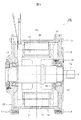
- FIG. 1 is a cross-sectional view of a rotary electric machine 100 to which the present invention is applied.
- the rotary electric machine 100 of the present embodiment is mounted on an automobile such as an electric vehicle having no internal combustion engine or a hybrid vehicle having an internal combustion engine, and has a function as an electric motor for generating a driving force and generates power when the automobile is braked. It has a function as a generator to perform.
- the generated electric power is stored in a battery or the like mounted on the automobile.
- the rotary electric machine 100 mainly includes a rotor 10 and a stator 20.
- the rotor 10 and the stator 20 are housed in a storage space formed of an annular housing 14 having openings on both sides, a front cover 15 closing the openings on both sides of the housing 14, and a rear cover 16.
- the front cover 15 and the rear cover 16 are fixed to the housing 14 by bolts 17.
- the rotor 10 is fixed to, for example, a substantially cylindrical rotor core 11 formed by laminating a plurality of flat plate-shaped electromagnetic steel plates along the direction of the axis L, and inside the center of the rotor core 11.
- the drive shaft 12 is provided.
- the rotor core 11 has a plurality of magnet insertion holes provided at equal intervals in the circumferential direction and a plurality of magnets (neodymium) inserted and fixed in the magnet insertion holes. Magnets and ferrite magnets) are provided.
- the drive shaft 12 is rotatably supported by two bearings 13 located at both ends, and is integrally rotated with the rotor core 11 around the axis L of the rotor core 11.
- the bearing 13 is arranged inside the front cover 15 and the rear cover 16.
- the bearing 13 on the side of the front cover 15 is supported by the retainer 18, and the retainer 18 is fixed to the front cover 15 by bolts 19.
- the drive shaft 12 applies a rotational force to the drive wheels (not shown) via a reduction mechanism (not shown), and also applies a rotational force from the drive wheels.
- the stator 20 is wound around, for example, a substantially annular-shaped stator core 21 formed by laminating a plurality of flat-plate-shaped electromagnetic steel sheets along the direction of the axis L, and the stator core 21. It is provided with a coil 30.
- the rotor core 11 is rotatably arranged with a minute gap in the radial direction D2 of the stator core 21, and the axis L of the stator core 21 and the axis of the rotor core 11 are rotatably arranged. It matches with L. Since the rotary electric machine having these configurations is a well-known configuration, further description thereof will be omitted.
- FIG. 2 is a view of the stator 20 of the rotary electric machine 100 shown in FIG. 1 taken out and viewed from diagonally above.
- a plurality of slit-shaped slots 22 are provided on the inner circumference of the annular stator core 21 at equal intervals in the circumferential direction D1 and extend radially outward in the radial direction D2. See).
- the slot 22 penetrates from one end face portion 21a to the other end face portion 21b along the direction of the axis L of the stator core 21 when viewed in the direction of the axis L of the stator core 21.
- the inner peripheral surface of the stator core 21 has an opening (slit) 22a continuous from one end surface portion 21a to the other end surface portion 21b along the direction of the axis L.
- stator core 21 for example, 48 slots 22 are formed at equal angles in the circumferential direction D1, and coils 30 are arranged in each slot 22. In this way, the slots 22 are formed radially on the stator core 21 with the axis L as the center.
- the coil 30 of the stator 20 has a first coil group 30A arranged on the inner peripheral side in the radial direction D2 of the stator core 21 and an outer peripheral side of the first coil group 30A. It is composed of a second coil group 30B arranged in.
- the first coil group 30A and the second coil group 30B are an aggregate of copper segment coils 31A and 31B.
- One coil end 35A, 35B of the coil 30 constitutes a first coil group 30A and a second coil group 30B in the direction of the axis L of the stator core 21, and the turn portions 33 of the segment coils 31A and 31B (FIG. 3). See). Further, the other coil ends 36A and 36B of the coil 30 are composed of a connecting portion 32 for connecting predetermined segment coils 31A and 31B having the same phase.
- the turn portion 33 is a bending side coil end 35A, 35B
- the connecting portion 32 is a connecting side coil end 36A, 36B
- the slot insertion portion 34 (see FIG. 3) is in between.
- the slot insertion portion 34 may be referred to as a straight portion 34.
- connection side coil ends 36A and 36B adjacent to each coil group are connected to each other by TIG welding by a connecting portion 32 for sequentially connecting the segment coils 31A and 31B. That is, the connecting portions 32 of the adjacent segment coils 31A of the first coil group 30A are sequentially connected, and the connecting portions 32 of the adjacent segment coils 31B of the second coil group 30B are sequentially connected. Since these configurations are also well known, further description will be omitted.
- the turn of the segment coil 31 constituting the coil 30 is performed.
- the shape of the portion 33 is important.
- FIG. 3 shows the shapes of the segment coils 31A and 31B. Since the segment coils 31A and 31B are formed in substantially the same shape, the configurations of the segment coils 31A and 31B will be described together. However, the segment coils 31A and 31B are characterized by a turn portion 33 that is bent outward in the radial direction when inserted into the slot 22, and this will be described in detail with reference to FIG.
- the segment coil 31 includes a pair of straight portions 34a and 34r arranged in the slot 22, and a turn portion 33 is formed so as to connect one side of the pair of straight portions 34a and 34r. Further, the other side of the pair of straight portions 34a and 34r is opened to form the connecting portions 32a and 32r. As a result, the bending side coil end 35 and the connecting side coil end 36 are formed.
- the turn portion 33 has a top 33c formed near the center, and the top 33c has segment coils 31 (plural) incorporated in the stator core 21 when the segment coil 31 is incorporated in the stator core 21.
- the top portions 33c are arranged so as to be in a positional relationship parallel to the core end face portion 21a.
- the turn portion 33 has a “mountain-shaped” shape from the viewpoint of the radial direction with the segment coil 31 arranged in the slot 22.
- the connecting portion 33aa between the intermediate inclined portion 33ba and the straight portion 34a and the connecting portion 33ar between the intermediate inclined portion 33br and the straight portion 34r have a bent shape, whereby the intermediate inclined portion 33ba and the top portion 33c, A pair of straight lines 34a and 34r are connected via the intermediate inclined portion 33br. Therefore, the segment coil 31 is formed in a substantially "U" shape from the pair of straight portions 34a and 34r and the turn portion 33 bent so as to connect the pair of straight portions 34a and 34r. ..
- the straight line portion on the front side in the clockwise rotation direction is set as the straight line portion 34a, and the clockwise rotation direction.
- the straight portion on the rear side is the straight portion 34r.
- the linear portions 34a and 34r of the segment coils 31A and 31B forming the first coil group 30A and the second coil group 30B are arranged in a form in which they are laminated in the radial direction.
- the laminated state is as shown in FIG. 4, which will be described with reference to FIG.
- the straight line portion 34r is arranged in an odd number layer, and the straight line portion 34a is arranged in an even number layer.
- the layer located on the innermost peripheral side of the slot 22 is the first layer, and the second layer, the third layer, and the fourth layer are formed toward the outer peripheral side.
- the coils 30 include a first coil group 30A arranged on the inner peripheral side in the radial direction D2 and a second coil group 30B arranged on the outer peripheral side of the first coil group 30A. have.
- the first coil group 30A and the second coil group 30B have two coil groups, but as in Patent Document 1, three or more coil groups are provided. Needless to say, it's okay.
- the coil 30 is composed of segment coils 31A and 31B having a rectangular wire having a rectangular cross-sectional shape from the viewpoint of suppressing a decrease in the space factor.
- segment coils 31A and 31B made of flat wire are used.
- an insulator 40 made of insulating paper or the like is arranged on the inner peripheral wall surface of each slot 22, and the segment coils 31A forming the first coil group 30A and the second coil group 30B, It covers the circumference of 31B.
- the pair of linear portions 34a and 34r of the segment coils 31A and 31B are inserted and arranged in the slot 22 extending in the direction of the axis L of the stator core 21 so as to be laminated in the radial direction D2.
- the part 34r is the first layer.
- the straight portion 34a of the second segment coil 31A constituting the first coil group 30A which is located outside the straight portion 34r of the first layer located on the innermost peripheral side, is a stator with respect to the first layer. It is a second layer adjacent to the outside of the radial D2 of the core 21.
- the first segment coil 31A and the second segment coil 31A are segment coils having the same shape, and the linear portions 34r and 34a of the respective segment coils 31A are separated by a predetermined pitch to form a stator core. It is arranged in a plurality of slots 22 arranged in a ring shape in 21, and a set of these slots constitutes a first coil group 30A.
- the straight portion located outside the second layer when viewed in the radial direction D2 of the stator core 21. 34r is the third layer.
- the linear portion 34a of the fourth segment coil 31B constituting the second coil group 30B is a fourth layer adjacent to the outer side of the stator core 21 in the radial direction D2 with respect to the third layer.
- the third segment coil 31B and the fourth segment coil 31B are also segment coils having the same shape, and the linear portions 34r and 34a of the respective segment coils 31B are separated by a predetermined pitch to form a stator core. It is arranged in a plurality of slots 22 arranged in a ring shape in 21, and a second coil group 30B is formed by a set thereof.
- the length (line length) of the turn portion 33 is formed longer than that of the segment coil 31A arranged on the inner peripheral side.
- the straight portion 34r of the segment coils 31A and 31B is arranged in the odd-numbered layer, and the straight portion 34a of the segment coils 31A and 31B is arranged in the even-numbered layer.
- the pair of linear portions 34a and 34r of the respective segment coils 31A and 31B are arranged in different slots 22 separated by a predetermined pitch interval in the circumferential direction D1 of the stator core 21.
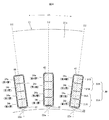
- FIG. 5 shows the arrangement relationship of the segment coils 31A and 31B when the slot 22 is viewed from the inside to the outside in the radial direction.
- the segment coil 31A of the first coil group 30A is shown by omitting the display of the segment coil 31B of the second coil group 39B. Further, in the slot 22 (region R) on the right side, the segment coil 31B of the second coil group 30B is shown in which the display of the segment coil 31A of the first coil group 30A is omitted.
- the straight portion 34r of the first segment coil 31A forming the first layer As shown in the region (L), the straight portion 34r of the first segment coil 31A forming the first layer, which is located on the innermost peripheral side of the slot 22, has an intermediate inclined portion 33br diagonally upward to the right in the drawing. It extends toward the slot 22 after the next predetermined pitch via.
- the straight portion 34a of the second segment coil 31A forming the second layer adjacent to the outer peripheral side in the radial direction of the first layer has a predetermined pitch via the intermediate inclined portion 33ba on the diagonally lower side in the drawing. It extends from the previous slot 22.
- the straight portion 34r of the third segment coil 31B forming the third layer located on the outer peripheral side of the second layer of the slot 22 is obliquely upward to the right when viewed in the drawing. It extends toward the slot 22 after the next predetermined pitch via the intermediate inclined portion 33br.
- the straight portion 34a of the fourth segment coil 31B forming the fourth layer adjacent to the outer peripheral side in the radial direction of the third layer is obliquely downward in the drawing via the intermediate inclined portion 33ba and before a predetermined pitch. It extends from slot 22 of.
- the odd-numbered straight line portion 34r laminated in the slot 22 faces the slot 22 after the next predetermined pitch via the intermediate inclined portion 33br on the diagonally upper right side in the drawing.
- the straight portion 34a of the even-numbered layer extends diagonally downward from the slot 22 before a predetermined pitch via the intermediate inclined portion 33ba as seen in the drawing.
- FIG. 6 shows the configuration of the turn portion 33 in a state where one segment coil 31 shown in FIG. 4 is inserted into the slot 22.
- the segment coil 31B of the second coil group 30B is shown, and as described above, the cross section of the segment coil 31B is formed in a rectangular shape in order to increase the space factor.
- the segment coil 31B constituting the second coil group 30B includes a turn portion 33 protruding from the slot 22 in the direction of the axis L of the stator core 21, and a pair of straight portions 34a and 34r penetrating the two predetermined slots 22. It is configured to have.
- the rotary electric machine 100 of the present embodiment is characterized by the shape of the turn portion 33 of the segment coil 31 wound around the slot 22 of the stator core 21.
- the open end side of the pair of straight portions 34a and 34r of the segment coil 31B penetrates the slot 22 in the direction of the axis L of the stator core 21 from the end face portion 21b on the opposite side of the end face portion 21a of the stator core 21. It projects outward along the direction of the axis L.
- the open end protruding in the direction of the axis L from the end face portion 21b of the stator core 21 on the opposite side of the turn portion 33 becomes the connection side coil end 36 and is sequentially connected by the connection portion 32 as shown in FIG. ..
- the turn portion 33 of the segment coil 31B is the top portion 33c formed of a “one side” that is farthest from the end face portion 21a of the stator core 21 and substantially parallel to the end face portion 21a when viewed in the direction of the axis L. have.
- the turn portion 33 is connected to both ends of the top portion 33c and has a pair of intermediate inclined portions 33ba and 33br extending downward in the drawing so as to approach the end surface portion 21a of the stator core 21. There is.
- the intermediate inclined portions 33ba and 33br are connected to the pair of straight portions 34a and 34r via the connecting portions 33aa and 33ar, respectively.
- the other straight line portion 34a is the second layer.
- the other straight line portion 34a is the fourth layer.
- the intermediate inclined portion 33br, the top portion 33c, and the intermediate inclined portion 33ba from one straight portion 34r (odd layer) to the other straight portion 34a (even layer) are orthogonal to the end face portion 21a of the stator core 21. Seen from the viewpoint, it is inclined by one layer from the inner peripheral side to the outer peripheral side.
- the turn portion 33 is curved in a "mountain shape" shape having the top 33c as the apex as a whole. Then, the top portions 33c and the intermediate inclined portions 33ba and 33br forming the turn portion 33 are located outside the pair of straight portions 34a and 33r in the radial direction D2 of the stator core 21 so that the bent portions 37a, It has an inclined shape that is bent outward in the radial direction starting from 37r and in a direction approaching the end face portion 21a.
- the apex 33c and the pair of intermediate inclined portions 33ba and 33br constituting the turn portion 33 are inclined so as to expand outward in the radial direction as they approach the apex 33c, starting from the bent portions 37a and 37r. Has and is bent.
- the segment coils 31A and 31B are preformed into the above-mentioned shape before being inserted into the slot 22.
- the top portion 33c and the pair of intermediate inclined portions 33ba and 33br constituting the turn portion 33 have the diameter of the stator core 21 when viewed from a viewpoint orthogonal to the end face portion 21a of the stator core 21 as described above. In the direction D2, it is inclined by one layer from the inner peripheral side to the outer peripheral side. Further, in addition to this, with respect to the axis L, the top portions 33c and the intermediate inclined portions 33ba and 33br move outward in the radial direction from the axis L and approach the end face portion 21a, starting from the bent portions 37a and 37r. It is tilted to do.
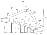
- FIG. 7 shows a state in which the second coil group 30B is removed in order to make it easier to understand the shape of the segment coil 31 constituting the coil 30.
- the pair of linear portions 34a and 34r of the individual segment coils 31A of the first coil group 30A are arranged in a pair of slots 22 separated by a predetermined pitch interval in the circumferential direction D1 of the stator core 21. Will be done.
- the pair of linear portions 34a and 34r of the respective segment coils 31A are arranged in the pair of slots 22 separated by 6 pitch intervals.
- one straight portion 34r is arranged on the innermost side of the stator core 21 in the radial direction D2 with respect to the other straight portion 34a (see FIG. 4). ..
- the pair of linear portions 34a and 34r of the respective segment coils 31 of the first coil group 30A are arranged in the pair of slots 22 separated by a predetermined pitch interval in the circumferential direction D1 of the stator core 21.
- 48 segment coils 31A are sequentially arranged in 48 slots 22 of the stator core 21.
- the first coil group 30A is composed of a plurality of segment coils 31A.
- the second coil group 30B has the same configuration.
- FIG. 8 shows an enlarged part of the first coil group 30A and the second coil group 30B constituting the coil 30 shown in FIG. In some slots 22, the display of the segment coil 31B of the fourth layer located on the outermost peripheral side is omitted.
- the turn portion 33 of the segment coil 31A constituting the first coil group 30A arranged on the inner peripheral side of the slot 22 the first coil group in the radial direction D2 of the stator core 21.
- a turn portion 33 of the segment coil 31B constituting the second coil group 30B is arranged outside the 30A.
- the segment coils 31A and 31B are inclined so as to expand outward in the radial direction D2 starting from the bent portions 37a and 37r.
- the coil 30 wound around the stator 20 is composed of the first coil group 30A and the second coil group 30B, and is wound around the slot 22 of the stator core 21 by "distributed winding of wave winding". ing. Needless to say, as described above, it may have three or more coil groups.
- the segment coils 31A and 31B are arranged in the same slot 22 in the arrangement form shown in FIG. Then, the straight line portion 34r (first layer) of the first segment coil 31A of the first coil group 30A is arranged from the inner peripheral side toward the outside in the radial direction, and the straight line portion 34r (first layer) of the first segment coil 31A of the first coil group 30A is arranged on the outer side. Part 34a (second layer) is arranged.
- a straight portion 34r (third layer) of the third segment coil 31B of the second coil group 30B is arranged outside the straight portion 34a (second layer) of the second segment coil 31A, and a third layer is arranged outside the straight portion 34r (third layer) of the third segment coil 31B.
- the straight line portion 34a (fourth layer) of the segment coil 31B of No. 4 is arranged.
- the intermediate inclined portion 33br connected to the straight portion 34r of the first layer and the third layer with the paper surface as a boundary extends so as to project toward the front side of the paper surface, and conversely, the second layer and the fourth layer
- the intermediate inclined portion 33ba connected to the straight portion 34a has a form extending from the back side of the paper surface so as to be connected to the straight portion 34a of the slot 22.
- the bent portion of the straight portion 34r arranged in the odd-numbered layer is the bent portion 37rA
- the bent portion of the straight portion 34a arranged in the even-numbered layer is bent.
- the bent portion 37aA in the segment coil 31B constituting the second coil group 30B, the bent portion of the straight portion 34r arranged in the odd-numbered layer is the bent portion 37rB
- the bent portion of the straight portion 34a arranged in the even layer is the bent portion 34a. Is described as a bent portion 37aB.
- the turn portion 33 forming the bending side coil end 35 starts from the bending portions 37aA, 37rA, portions 37aB, 37rB with the straight portions 34a, 34r of the laminated segment coils 31 as the starting points, and the axis L It has an inclined shape that is bent outward in the radial direction D2 of the stator core 21 with respect to the direction of.
- the top portion 33c constituting the turn portion 33 and the pair of intermediate inclined portions 33ba and 33br are inclined in a direction gradually moving outward from the axis L starting from the bent portions 37aA and 37rA and the portions 37aB and 37rB. In this case, the top 33c is farthest from the axis L.
- the straight portion 34r of the first segment coil 31A constituting the first layer of the first coil group 30A arranged on the innermost peripheral side of the radial direction D2 of the slot 22 is bent.
- the shape is such that the portion 37rA is not formed. That is, the straight line portion 34r extends substantially parallel to the axis L and is connected to the intermediate inclined portion 33br.
- a bent portion 37rA may be formed on the straight portion 34r of the first segment coil 31A constituting the first layer of the first coil group 30A.
- the inclination angle ⁇ of the bent portions 37aA, 37rB, 37aB of the straight portions 34a, 34r of the segment coils 31A, 31B laminated along the radial direction D2 is the straight line of the segment coils 31A, 31B.
- the portions 34a and 34r are set so large that they are located on the outer peripheral side of the slot 22 in the radial direction D2.
- the inclination angle ⁇ means the angle formed by the line segment from the bent portions 37aA, 37rB, and 37aB to the top 33c of the turn portion 33 and the axis L of the stator core 21.
- the inclination angle ⁇ 1 of the bent portion 37aA of the second layer, the inclination angle ⁇ 2 of the bent portion 37rB of the third layer, and the inclination angle ⁇ 3 of the bent portion 37aB of the fourth layer are “ ⁇ 1 ⁇ 2 ⁇ 3”.
- the inclination angle ⁇ is not limited to this, and an appropriate angle may be selected.
- angle difference ⁇ between the respective inclination angles ⁇ 1, ⁇ 2, and ⁇ 3 is set to be equal to “2.5 °”, but it goes without saying that they may be set to unequal angles. .. It is also possible to set the angle difference ⁇ to be larger toward the outside, or to set the angle difference ⁇ to be larger toward the inside.
- the bent portion 37aA of the straight portion 34a of the second layer, the bent portion 37rB of the straight portion 34r of the third layer, and the bent portion 37aB of the straight portion 34a of the fourth layer are located on the outer peripheral side of the radial direction D2 of the slot 22.
- the top portion 33c is also formed so that the turn portion 33 located on the outer peripheral side of the slit 22 in the radial direction D2 is closer to the end surface portion 21a of the stator core 21 when viewed in the direction of the axis L.
- FIG. 10 is a view of the first coil group 30A and the second coil group 30B shown in FIG. 8 from different viewpoints.
- the two segment coils 31A and 31B that are adjacent to each other in the circumferential direction D1 of the stator core 21 are located between the two tops 33c that are adjacent to each other in the circumferential direction D1 of the stator core 21. It is shown that they face each other with a gap G in the radial direction D2.
- the gap G allows the cooling medium to smoothly flow into the turn portion 33, and the coil 30 can be efficiently cooled.
- the rotary electric machine 100 of the present embodiment includes a stator core 21, a plurality of slots 22 provided in the stator core 21, and segment coils 31A and 31B arranged in the slots 22. ing.
- the segment coils 31A and 31B have a pair of straight line portions 34a and 34r arranged in different slots 22 and a turn portion 33 connecting the pair of straight line portions 34a and 34r. ..
- the turn portion 33 has a pair of intermediate inclined portions 33ba and 33br connected to the straight portions 34a and 34r.
- bent portions 37a and 37r are provided between the straight portions 34a and 34r and the turn portion 33, and the inclination angle ⁇ of the bent portions 37a and 37r becomes larger as it is located on the outer peripheral side of the radial direction D2 of the slot 22. It is set.
- the inclination angle ⁇ 1 of the bent portion 37aA formed in the straight portion 34a of the second layer the inclination angle ⁇ 2 of the bent portion 37rB formed in the straight portion 34r of the third layer, and the straight portion 34a of the fourth layer. It has a relationship of “ ⁇ 1 ⁇ 2 ⁇ 3” with the inclination angle ⁇ 3 of the bent portion 37aB formed in.
- the bent portions 37a and 37r are bent so that the turn portion 33 is inclined in the direction away from the axis L so that the segment coils 31A and 31B are located on the outer peripheral side in the radial direction D2 of the slot 22. That is, as the segment coil 31 is located on the outer peripheral side in the radial direction D2 of the slot 22, the top portion 33c and the intermediate inclined portions 33ba and 33br are closer to the end face portion 21a of the stator core 21 when viewed in the direction of the axis L. It is folded into.
- a sufficient gap is formed in the turn portions 33 adjacent to each other in the circumferential direction D1 of the stator core 21 to avoid mechanical interference, and the cooling medium can easily enter the gap, or the coil and the cooling are cooled.
- the cooling performance can be improved by increasing the substantial contact area of the medium.
- the two tops 33c adjacent to each other in the circumferential direction D1 face each other with a gap G in the radial direction D2.
- the cooling medium easily enters the gap G, or the contact area of the coil 30 with the cooling medium becomes large, so that the cooling effect can be enhanced.
- the segment coils 31A and 31B that are adjacent to each other in the circumferential direction D1 of the stator core 21 are located between the two tops 33c that are adjacent to each other in the circumferential direction D1 of the stator core 21. They face each other with a gap G in the radial direction D2.
- the cooling performance is improved by avoiding the interference of the turn portions 33 of the bending side coil ends 35A and 35B without increasing the length of the coil end 35. Can be made to.
- the inclination angle ⁇ 1 of the bent portion 37aA formed in the straight portion 34a of the second layer the inclination angle ⁇ 2 of the bent portion 37rB formed in the straight portion 34r of the third layer, and the straight line of the fourth layer.
- the inclination angle ⁇ 3 of the bent portion 37aB formed in the portion 34a has a relationship of “ ⁇ 1 ⁇ 2 ⁇ 3”.
- the inclination angle ⁇ 1 of the bent portion 37aA formed in the straight portion 34a of the second layer and the inclination angle ⁇ 2 of the bent portion 37rB formed in the straight portion 34r of the third layer are
- the turn portion 33 is configured to be inclined outward in the radial direction, so that the space where the segment coils 31A and 31B exist is large. Can be taken.
- the two tops 33c adjacent to each other in the circumferential direction D1 face each other with a gap G in the radial direction D2.
- the cooling medium easily enters the gap G, or the contact area of the coil 30 with the cooling medium becomes large, so that the cooling effect can be enhanced.
- the two tops 33c adjacent to each other in the circumferential direction D1 face each other with a gap G in the radial direction D2 of the stator core 21.
- the line length of the turn portion 33 of the segment coil 31A located on the inner peripheral side and the line length of the turn portion 33 of the segment coil 31B located on the outer peripheral side are on the outer peripheral side having a long radius.
- the segment coil 31B located is longer. Therefore, the coil resistance increases by this amount, and the amount of heat generated also increases. If only one segment coil 31B is used, the effect is not as great as on the left, but since a plurality of segment coils 31B, for example, n segment coils 31B are connected in series, the coil resistance becomes n times and can be ignored. There is a risk that it will disappear.
- the bent portion of the straight portion 34r arranged in the odd-numbered layer is changed to the bent portion 37rA and the even-numbered layer.
- the bent portion of the linear portion 34a to be arranged is the bent portion 37aA
- the bent portion of the straight portion 34r arranged in the odd-numbered layer is arranged in the bent portion 37rB and the even-numbered layer in the segment coil 31B constituting the second coil group 30B.
- the forming positions of the bent portion 37aA of the straight portion 34a of the second layer, the bent portion 37rB of the straight portion 34r of the third layer, and the bent portion 37aB of the straight portion 34a of the fourth layer are The closer to the outer peripheral side of the slot 22 in the radial direction D2, the closer it is to the end face portion 21a of the stator core 21 when viewed in the direction of the axis L.
- the relationship between the length "S2" to the end face portion 21a of the coil 21 and the length "S3" from the bending point of the bending portion 37aB of the straight portion 34a of the fourth layer to the end face portion 21a of the stator coil 21 is "S3". It has a relationship of ⁇ S2 ⁇ S1 ".
- the length from the bent portions 37aB and 37rB of the segment coil 31B located on the outer peripheral side to the end face portion 21a of the stator coil 21 is shortened.
- the wire length of the turn portion 33 of the segment coil 31B located on the outer peripheral side can be shortened, the increase in coil resistance can be suppressed, and the amount of heat generated can also be suppressed.
- the bent portions 37rA, 37aA, 37rB, and 37aB are formed so that the lengths of the turn portion 33 of the segment coil 31A on the inner peripheral side and the segment coil 31B on the outer peripheral side are set to substantially the same length. The position is fixed.
- the segment coil has a first straight line portion inserted into a specific slot and a second straight line portion inserted into another specific slot different from the specific slot.
- a turn portion having a top extending from one end face portion of the stator core toward the outside in the axial direction of the stator core and connecting the first straight portion and the second straight portion, respectively.
- the linear portions of the plurality of segment coils are inserted and arranged so as to be laminated from the inner peripheral side to the outer peripheral side in the radial direction, and the linear portions of the segment coils laminated in the radial direction are inserted and arranged.
- a bent portion is formed between the turn portions, and the bent portion inclines the top of the turn portion toward the end face of the stator core.
- the present invention is not limited to the above-described embodiment, and includes various modifications.
- the above-described embodiment has been described in detail in order to explain the present invention in an easy-to-understand manner, and is not necessarily limited to the one including all the described configurations.
- it is possible to replace a part of the configuration of one embodiment with the configuration of another embodiment and it is also possible to add the configuration of another embodiment to the configuration of one embodiment.
Landscapes
- Engineering & Computer Science (AREA)
- Power Engineering (AREA)
- Windings For Motors And Generators (AREA)
Abstract
ターン部が位置する側のコイルエンドの高さが高くなるのを抑制し、しかもセグメントコイルのターン部周辺の冷却性能を向上できる新規な回転電機を提供する。 セグメントコイル31が、特定のスロット22に挿入される第1の直線部34rと、特定のスロット22とは異なる他の特定のスロット22に挿入される第2の直線部34aと、固定子コア21の一方の端面部から固定子コア21の軸線方向の外側に向けて延び、第1の直線部34r、及び第2の直線部34aとを接続する頂部33cを有するターン部33とを備え、夫々のスロット22には、径方向に内周側から外周側に積層されるように複数のセグメントコイル31の夫々の直線部34r、34aが挿入、配置されると共に、径方向に積層されたセグメントコイル31の夫々の直線部34r、34aとターン部33の間に屈曲部37が形成され、この屈曲部37がターン部33の頂部33cを固定子コア21の端面に近づく方向に傾斜させている。
Description
本発明は回転電機に係り、特に複数のスロットを有する固定子コアと、この固定子コアのスロットに収納される複数のセグメントコイルとを備えた固定子を有する回転電機に関するものである。
電気自動車やハイブリッド車においては、回転電機によって駆動力を得る構成とされており、この回転電機としては、複数のスロットを有する固定子コアと、この固定子コアのスロットに収納される銅製の複数のセグメントコイルとを備えた固定子を有する回転電機が使用されている。このような固定子を備えた回転電機は、例えば特開2017-189020号公報(特許文献1)に記載されている。
この特許文献1に記載された回転電機においては、内周面に複数の軸方向に延びたスロットを有する固定子コアと、このスロットに挿入された銅製のセグメントコイルとを備えており、固定子コアの端面部から軸方向に突出したセグメントコイルのコイルエンドの折り曲げ側(いわゆるターン部と称されている)の部位の頂部に、固定子コアの端面部と略平行な平行部が形成されている。
そして、この平行部を境にして一方の中間傾斜部には、1つの所定角度からなる傾斜を有する中間傾斜部が形成され、他方の中間傾斜部には、2つの異なった所定角度からなる2段傾斜を有する中間傾斜部が形成されている。
このような構成のセグメントコイルによれば、セグメントコイルの折り曲げ側コイルエンドにおける、隣接するコイル間の機械的な干渉を避けつつ、コイルエンドの長さを抑えた回転電機の固定子を提供することが可能となる。
ところで、この種の回転電機においては、固定子コアの端面部から突出したセグメントコイルの折り曲げ側コイルエンドを形成するターン部と、これに隣接するセグメントコイルの折り曲げ側コイルエンドのターン部との空間距離が小さい場合、電流を通電した時のコイルに発生した熱が空気、或いは油等の冷却媒体中に発散され難いため、コイルの電気抵抗が上昇して回転電機の性能低下を招く虞がある。
この対策として、固定子コアの端面部とセグメントコイルのターン部との空間距離を大きくすることで、冷却媒体がターン部と接する接触面積を大きくする方法があるが、ターン部の高さ、即ち折り曲げ側コイルエンドの長さが増加して小型化を阻害するという課題がある。このため、折り曲げ側コイルエンドの長さを長くしなくても、折り曲げ側コイルエンドの充分な冷却が可能な回転電機が求められている。
本発明は、この種の回転電機における、上述の様な課題を解決することを目的としたものである。
即ち、本発明の目的は、ターン部が位置する側のコイルエンドの長さが長くなるのを抑制し、しかもセグメントコイルのターン部周辺の冷却性能を向上できる新規な回転電機を提供することにある。
本発明の特徴は、
セグメントコイルが、特定のスロットに挿入される第1の直線部と、特定のスロットとは異なる他の特定のスロットに挿入される第2の直線部と、固定子コアの一方の端面部から固定子コアの軸線方向の外側に向けて延び、第1の直線部、及び第2の直線部とを接続する頂部を有するターン部とを備え、夫々のスロットには、径方向に内周側から外周側に積層されるように複数のセグメントコイルの夫々の直線部が挿入、配置されると共に、径方向に積層されたセグメントコイルの夫々の直線部とターン部の間に屈曲部が形成され、この屈曲部がターン部の頂部を固定子コアの端面に近づく方向に傾斜させている、ところにある。
セグメントコイルが、特定のスロットに挿入される第1の直線部と、特定のスロットとは異なる他の特定のスロットに挿入される第2の直線部と、固定子コアの一方の端面部から固定子コアの軸線方向の外側に向けて延び、第1の直線部、及び第2の直線部とを接続する頂部を有するターン部とを備え、夫々のスロットには、径方向に内周側から外周側に積層されるように複数のセグメントコイルの夫々の直線部が挿入、配置されると共に、径方向に積層されたセグメントコイルの夫々の直線部とターン部の間に屈曲部が形成され、この屈曲部がターン部の頂部を固定子コアの端面に近づく方向に傾斜させている、ところにある。
本発明によれば、固定子コアの端面部から延びたターン部が径方向で外側に向かって折り曲げられていることで、夫々のセグメントコイルのターン部の間に充分な間隙が形成され、この間隙に冷却媒体が進入し易くなる、或いはコイルと冷却媒体の実質的な接触面積が大きくなることで、冷却性能の向上を図ることができる。
以下、本発明の実施形態について図面を用いて詳細に説明するが、本発明は以下の実施形態に限定されることなく、本発明の技術的な概念の中で種々の変形例や応用例をもその範囲に含むものである。
図1は、本発明が適用される回転電機100の断面図である。本実施形態の回転電機100は、例えば、内燃機関を有しない電気自動車や内燃機関を有するハイブリッド車等の自動車に搭載され、駆動力を発生させる電動機としての機能と、自動車の制動時等に発電を行う発電機としての機能とを備えている。尚、発電された電力は自動車に搭載されているバッテリ等に蓄電される。
回転電機100は、主に、回転子10と固定子20とを備えている。回転子10と固定子20は、両側が開口された円環状のハウジング14と、このハウジング14の両側の開口を塞ぐフロントカバー15、及びリアカバー16から形成された収納空間に収納されている。フロントカバー15、及びリアカバー16は、ハウジング14にボルト17によって固定されている。
回転子10は、例えば、複数の平板状の電磁鋼鈑を軸線Lの方向に沿って積層することによって構成された概ね円柱形状の回転子コア11と、この回転子コア11の中央内部に固定された駆動シャフト12とを備えている。尚、図示は省略しているが、回転子コア11は、周方向に等角度の間隔で設けられた複数の磁石挿入孔と、この磁石挿入孔に挿入されて固定された複数の磁石(ネオジム磁石やフェライト磁石)とが備えられている。
駆動シャフト12は、両端に位置する2つの軸受13によって回転自在に軸支され、回転子コア11の軸線Lを中心に回転子コア11と一体的に回転される。軸受13は、フロントカバー15、及びリアカバー16の内側に配置されている。フロントカバー15の側の軸受13は、リテーナ18によって支持され、リテーナ18はボルト19によってフロントカバー15に固定されている。尚、駆動シャフト12は、減速機構(図示せず)を介して、駆動輪(図示せず)に回転力を与え、また、駆動輪から回転力が与えられる。
固定子20は、例えば、複数の平板状の電磁鋼鈑を軸線Lの方向に沿って積層することによって構成された概ね円環形状の固定子コア21と、この固定子コア21に巻回されたコイル30とを備えている。
固定子コア21の内側には、固定子コア21の径方向D2に微小な隙間を有して回転子コア11が回転自在に配置され、固定子コア21の軸線Lと回転子コア11の軸線Lとが一致している。これらの構成の回転電機は良く知られた構成であるので、これ以上の説明は省略する。
図2は、図1に示す回転電機100の固定子20を取り出して斜め上方から見たものである。図2において、円環状の固定子コア21の内周には、周方向D1に等角度の間隔で設けられ、径方向D2で外側に向かって放射状に延びる複数のスリット状のスロット22(図4参照)を有している。
スロット22は、固定子コア21の軸線Lの方向で見て、一方の端面部21aから他方の端面部21bまで、固定子コア21の軸線Lの方向に沿って貫通している。そして、固定子コア21の内周面に、軸線Lの方向にそって一方の端面部21aから他方の端面部21bまで連続する開口部(スリット)22aを有している。
固定子コア21は、例えば48箇のスロット22が、周方向D1に等角度に形成されており、各スロット22にコイル30が配置されている。このように、スロット22は、軸線Lを中心にして、固定子コア21に放射状に形成されることになる。
また、図2に示すように、固定子20のコイル30は、固定子コア21の径方向D2において、内周側に配置された第1コイル群30Aと、この第1コイル群30Aの外周側に配置された第2コイル群30Bとによって構成されている。第1コイル群30A、及び第2コイル群30Bは、銅製のセグメントコイル31A、31Bの集合体である。
固定子コア21の軸線Lの方向において、コイル30の一方のコイルエンド35A、35Bは、第1コイル群30Aと第2コイル群30Bを構成する、セグメントコイル31A、31Bのターン部33(図3参照)によって構成されている。また、コイル30の他方のコイルエンド36A、36Bは、同相の所定のセグメントコイル31A、31Bを接続する接続部32によって構成されている。
ここで、ターン部33は、折り曲げ側コイルエンド35A、35Bとされ、接続部32は、接続側コイルエンド36A、36Bとされ、その間はスロット挿入部34(図3参照)とされている。尚、スロット挿入部34は図3に示すように、直線部34と記載することもある。
また、コイル群毎に隣接する接続側コイルエンド36A、36Bは、セグメントコイル31A、31Bを順次接続する接続部32によって互いにTIG溶接によって接続されている。つまり、第1コイル群30Aの隣接するセグメントコイル31Aの接続部32が順次接続され、第2コイル群30Bの隣接するセグメントコイル31Bの接続部32が順次接続されている。これらの構成も良く知られているので、これ以上の説明は省略する。
そして、固定子コア21の軸線Lの方向において、固定子コア21の一方の端面部21aから突出する折り曲げ側コイルエンド35の冷却性能を向上するには、コイル30を構成するセグメントコイル31のターン部33の形状が重要になる。
以下、本実施形態の回転電機100の特徴であるセグメントコイル31のターン部33の構成について、図面を使用しながら詳細に説明する。
図3にセグメントコイル31A、31Bの形状を示している。セグメントコイル31A、31Bは実質的に同じ形状に形成されているので、セグメントコイル31A、31Bの構成をまとめて説明する。ただ、セグメントコイル31A、31Bは、スロット22に挿入した時における、径方向で外側に折り曲げられたターン部33に特徴があり、これについては、図9で詳細に説明する。
図3において、セグメントコイル31は、スロット22に配置される一対の直線部34a、34rを備えており、一対の直線部34a、34rの一方側を繋ぐようにターン部33が形成されている。また、一対の直線部34a、34rの他方側が開放されて、接続部32a、32rが形成されている。これによって、折り曲げ側コイルエンド35と、接続側コイルエンド36が形成されている。
ターン部33は、中央付近に頂部33cが形成されており、この頂部33cは、固定子コア21にセグメントコイル31が組み込まれたときに、固定子コア21に組み込まれたセグメントコイル31(複数)の頂部33cの並びがコア端面部21aと平行な位置関係になるように形成されている。
そして、この頂部33cの一方の側で、中間傾斜部33baを介して直線部34aに接続され、頂部33cの他方の側で、中間傾斜部33brを介して直線部34rに接続されている。したがって、ターン部33は、セグメントコイル31をスロット22に配置した状態で、径方向から見た視点で、形状が「山形」の形状とされている。
尚、中間傾斜部33baと直線部34aの接続部33aaと、中間傾斜部33brと直線部34rの接続部33arは、折り曲げられた形状となっており、これによって、中間傾斜部33ba、頂部33c、及び中間傾斜部33brを介して、一対の直線部34a、34rを繋いでいる。したがって、一対の直線部34a、34rと、この一対の直線部34a、34rを接続するように折り曲げられたターン部33とから、セグメントコイル31は略「U」字形状に形成されることになる。
ここで、一対の直線部34a、34rは、セグメントコイル31を所定ピッチ分だけ離間した2つのスロット22に配置した状態において、時計回転方向で前側にある直線部を直線部34aとし、時計回転方向で後側にある直線部を直線部34rとしている。
後述するように、スロット22には、第1コイル群30A、及び第2コイル群30Bを形成するセグメントコイル31A、31Bの直線部34a、34rが、径方向に向けて積層される形態に配置される。積層された状態は図4に示している通りであり、これについては図4を用いて説明する。
そして、1つのスロット22内において、直線部34rは奇数層に配置され、直線部34aは偶数層に配置される構成となっている。尚、本実施形態では、スロット22の最も内周側に位置する層を第1層とし、外周側に行くにしたがって第2層、第3層、第4層としている。
図4に示しているように、コイル30は、径方向D2の内周側に配置された第1コイル群30Aと、この第1コイル群30Aの外周側に配置された第2コイル群30Bとを有している。尚、本発明の実施形態では、第1コイル群30A、及び第2コイル群30Bからなる2つのコイル群を有しているが、特許文献1のように3つ以上のコイル群を有していても良いことはいうまでもない。
また、コイル30は、占積率の低下を抑制する観点から、断面形状が矩形である平角線からなるセグメントコイル31A、31Bによって構成することが望ましい。もちろん、回転電機の仕様によっては、断面形状が円形のコイルを使用することも可能である。本実施形態では、平角線からなるセグメントコイル31A、31Bを使用している。
図4に示しているように、夫々のスロット22の内周壁面には、絶縁紙等からなるインシュレータ40が配置され、第1コイル群30A、及び第2コイル群30Bを構成するセグメントコイル31A、31Bの周囲を覆っている。セグメントコイル31A、31Bの一対の直線部34a、34rは、固定子コア21の軸線Lの方向に延びたスロット22に、径方向D2に積層される形で挿入、配置されている。
そして、第1コイル群30Aを構成する第1のセグメントコイル31Aの一対の直線部34a、34rのうち、固定子コア21の径方向D2で見て、スロット22の最も内周側に位置する直線部34rは第1層とされている。また、最も内周側に位置する第1層の直線部34rの外側に位置する、第1コイル群30Aを構成する第2のセグメントコイル31Aの直線部34aは、第1層に対して固定子コア21の径方向D2の外側に隣接する第2層とされている。
このように、第1のセグメントコイル31Aと、第2のセグメントコイル31Aは、同じ形状のセグメントコイルであり、夫々のセグメントコイル31Aの直線部34r、34aは所定ピッチだけ離間して、固定子コア21に環状に配置された複数のスロット22に配置され、これらの集合で第1コイル群30Aが構成される。
同様に、第2コイル群30Bを構成する第3のセグメントコイル31Bの一対の直線部34a、34rのうち、固定子コア21の径方向D2で見て、第2層の外側に位置する直線部34rは第3層とされている。また、第2コイル群30Bを構成する第4セグメントコイル31Bの直線部34aは、第3層に対して固定子コア21の径方向D2の外側に隣接する第4層とされている。
このように、第3のセグメントコイル31Bと、第4のセグメントコイル31Bも、同じ形状のセグメントコイルであり、夫々のセグメントコイル31Bの直線部34r、34aは所定ピッチだけ離間して、固定子コア21に環状に配置された複数のスロット22に配置され、これらの集合で第2コイル群30Bが構成される。
ただ、セグメントコイル31Bは外周側に配置されるので、内周側に配置されるセグメントコイル31Aに比べて、ターン部33の長さ(線長)が長く形成されている。
このように、本実施形態においては、奇数層にはセグメントコイル31A、31Bの直線部34rが配置され、偶数層にはセグメントコイル31A、31Bの直線部34aが配置されている。上述したように、夫々のセグメントコイル31A、31Bの一対の直線部34a、34rは、固定子コア21の周方向D1で所定のピッチ間隔で離れた異なるスロット22に配置される。
図5は、スロット22を径方向で内側から外側方向を見た時の、夫々のセグメントコイル31A、31Bの配置関係を示している。
左側のスロット22(領域L)においては、第2コイル群39Bのセグメントコイル31Bの表示を省略した、第1コイル群30Aのセグメントコイル31Aを示している。また、右側のスロット22(領域R)においては、第1コイル群30Aのセグメントコイル31Aの表示を省略した、第2コイル群30Bのセグメントコイル31Bを示している。
領域(L)に示すように、スロット22の最も内周側に位置する、第1層を形成する第1のセグメントコイル31Aの直線部34rは、図面で見て右斜め上側に中間傾斜部33brを介して次の所定ピッチ後のスロット22に向かって延びている。一方、第1層の径方向で外周側に隣接する第2層を形成する第2のセグメントコイル31Aの直線部34aは、図面で見て斜め下側に中間傾斜部33baを介して、所定ピッチ前のスロット22から延びてきている。
同様に、領域(R)に示すように、スロット22の第2層の外周側に位置する第3層を形成する第3のセグメントコイル31Bの直線部34rは、図面で見て右斜め上側に中間傾斜部33brを介して次の所定ピッチ後のスロット22に向かって延びている。一方、第3層の径方向で外周側に隣接する第4層を形成する第4のセグメントコイル31Bの直線部34aは、図面で見て斜め下側に中間傾斜部33baを介して所定ピッチ前のスロット22から延びてきている。
このように、セグメントコイル31A、31Bにおいて、スロット22に積層される奇数層の直線部34rは、図面で見て右斜め上側に中間傾斜部33brを介して次の所定ピッチ後のスロット22に向かって延び、偶数層の直線部34aは、図面で見て斜め下側に中間傾斜部33baを介して所定ピッチ前のスロット22から延びてきている。
図6は、図4に示す1つのセグメントコイル31をスロット22に挿入した状態のターン部33の構成を示している。ここでは、第2コイル群30Bのセグメントコイル31Bを示しており、上述したようにセグメントコイル31Bの断面は、占積率を高めるために矩形状に形成されている。
第2コイル群30Bを構成するセグメントコイル31Bは、スロット22から固定子コア21の軸線Lの方向に突出するターン部33と、所定の2つのスロット22を貫通する一対の直線部34a、34rとを有する構成とされている。そして、本実施形態の回転電機100は、この固定子コア21のスロット22に巻回されたセグメントコイル31のターン部33の形状に特徴を有している。
セグメントコイル31Bの一対の直線部34a、34rの開放端側は、固定子コア21の軸線Lの方向にスロット22を貫通し、固定子コア21の端面部21aとは反対側の端面部21bから軸線Lの方向に沿って外側に突出する。ターン部33と反対側の固定子コア21の端面部21bから軸線Lの方向に突出した開放端は、接続側コイルエンド36となって、図2に示すように接続部32によって順次接続される。
セグメントコイル31Bのターン部33は、図6に示すように、軸線Lの方向で見て、固定子コア21の端面部21aから最も離れ、端面部21aと略平行な「一辺」よりなる頂部33cを有している。
また、ターン部33は、この頂部33cの両端に接続され、固定子コア21の端面部21aに近づくように、図面で下側に傾斜して延びる一対の中間傾斜部33ba、33brを有している。そして、夫々の中間傾斜部33ba、33brは、接続部33aa、33arを介して一対の直線部34a、34rと接続されている。
上述したように、第1コイル群30Aのセグメントコイル31Aの一方の直線部34rが第1層の場合、他方の直線部34aは第2層となる。同様に、第2コイル群30Bのセグメントコイル31Bの一方の直線部34rが第3層の場合、他方の直線部34aは第4層となる。
したがって、一方の直線部34r(奇数層)から他方の直線部34a(偶数層)に至る、中間傾斜部33br、頂部33c、及び中間傾斜部33baは、固定子コア21の端面部21aに直交する視点で見て、内周側から外周側に向けて一層分だけ傾斜していることになる。
また、図6に示しているように、ターン部33は、全体として頂部33cを頂点とする「山形」の形状に湾曲している。そして、ターン部33を構成する頂部33c、及び中間傾斜部33ba、33brは、一対の直線部34a、33rに対して固定子コア21の径方向D2で外側に位置するように、屈曲部37a、37rを起点として径方向で外側に、端面部21aに接近する方向に折り曲げられた傾斜形状とされている。
つまり、ターン部33を構成する頂部33c、及び一対の中間傾斜部33ba、33brは、屈曲部37a、37rを起点にして、頂部33cに近づくほど径方向で外側に大きく拡開するように傾斜を有して折り曲げられている。尚、セグメントコイル31A、31Bは、スロットに22に挿入される前に、上述した形状に予め成形されている。
したがって、ターン部33を構成する、頂部33c、及び一対の中間傾斜部33ba、33brは、上述したように、固定子コア21の端面部21aに直交する視点で見て、固定子コア21の径方向D2で内周側から外周側に向かって1層分だけ傾斜している。また、これに加えて軸線Lに対して、屈曲部37a、37rを起点にして、頂部33c、及び中間傾斜部33ba、33brが、軸線Lから径方向で外側に遠ざかり、しかも端面部21aに接近するように傾斜している。
そして、このように形成されたセグメントコイル31は、夫々のスロット22に挿入、配置されることになる。図7においては、コイル30を構成するセグメントコイル31の形状を理解しやすくするために、第2コイル群30Bを取り外した状態を示している。
図7に示すように、第1コイル群30Aの個々のセグメントコイル31Aの一対の直線部34a、34rは、固定子コア21の周方向D1に所定のピッチ間隔で離れた一対のスロット22に配置される。図7に示す例においては、夫々のセグメントコイル31Aの一対の直線部34a、34rは、6ピッチ間隔で離れた一対のスロット22に配置されている。夫々のセグメントコイル31Aの一対の直線部34a、34rのうち、一方の直線部34rは、他方の直線部34aよりも固定子コア21の径方向D2の最も内側に配置(図4参照)される。
このように、第1コイル群30Aの夫々のセグメントコイル31の一対の直線部34a、34rは、固定子コア21の周方向D1に所定のピッチ間隔で離れた一対のスロット22に配置される。本実施形態においては、固定子コア21の48箇のスロット22に、48個のセグメントコイル31Aが順次配置される。
そして、スロット22に配置された夫々のセグメントコイル31Aの一対の直線部34a、34rのターン部33とは反対側の端部(接続側コイルエンド)を接続部32a,32rによって順次接続することで、複数のセグメントコイル31Aによって第1コイル群30Aが構成される。もちろん、第2コイル群30Bも同様の構成となっていることは言うまでもない。
図8は、図2に示すコイル30を構成する第1コイル群30Aと第2コイル群30Bの一部を拡大して示している。尚、一部のスロット22では、最も外周側に位置する第4層のセグメントコイル31Bの表示を省略している。
図8に示すように、スロット22の内周側に配置された第1コイル群30Aを構成するセグメントコイル31Aのターン部33に対して、固定子コア21の径方向D2で、第1コイル群30Aの外側に、第2コイル群30Bを構成するセグメントコイル31Bのターン部33が配置されている。そして、夫々のセグメントコイル31A、31Bは、屈曲部37a、37rを起点として、径方向D2で外側に向けて拡開するように傾斜されている。
このように、固定子20に巻回されるコイル30は、第1コイル群30Aと第2コイル群30Bによって構成され、「波巻きの分布巻き」で固定子コア21のスロット22に巻回されている。尚、上述したように、3つ以上のコイル群を有しても良いことはいうまでもない。
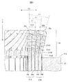
次に、本実施形態の特徴となるターン部33の具体的な形状について、図9を基に詳細に説明する。ここで、図9においては、図4におけるスロット22を径方向で軸線Lの方向に延びる面で断面しているので、複数のセグメントコイル31の断面が表示されている。以下では、本実施形態に関係する部分について説明する。
図9に示すように、同一のスロット22において、図5に示した配置形態で夫々のセグメントコイル31A、31Bが配置されている。そして、径方向で外側に向けて内周側から、第1コイル群30Aの第1のセグメントコイル31Aの直線部34r(第1層)が配置され、その外側に第2のセグメントコイル31Aの直線部34a(第2層)が配置されている。
更に、第2のセグメントコイル31Aの直線部34a(第2層)の外側に、第2コイル群30Bの第3のセグメントコイル31Bの直線部34r(第3層)が配置され、その外側に第4のセグメントコイル31Bの直線部34a(第4層)が配置されている。
したがって、紙面を境にして、第1層、及び第3層の直線部34rに繋がる中間傾斜部33brは、紙面の手前側に突出するように延び、逆に第2層、及び第4層の直線部34aに繋がる中間傾斜部33baは、紙面の奥側からスロット22の直線部34aに繋がるように延びる形態となっている。
尚、図9においては、第1コイル群30Aを構成するセグメントコイル31Aで、奇数層に配置される直線部34rの屈曲部を屈曲部37rA、偶数の層に配置される直線部34aの屈曲部を屈曲部37aAと表記し、第2コイル群30Bを構成するセグメントコイル31Bで、奇数層に配置される直線部34rの屈曲部を屈曲部37rB、偶数層に配置される直線部34aの屈曲部を屈曲部37aBと表記している。
そして、同一のスロット22において、折り曲げ側コイルエンド35を形成するターン部33は、積層されたセグメントコイル31の直線部34a、34rを屈曲部37aA、37rA、部37aB、37rBを起点として、軸線Lの方向に対して固定子コア21の径方向D2で外側に向かって折り曲げられた傾斜形状とされている。
つまり、ターン部33を構成する頂部33c、及び一対の中間傾斜部33ba、33brは、屈曲部37aA、37rA、部37aB、37rBを起点として、軸線Lから外側に次第に遠ざかる方向に傾斜されている。この場合、頂部33cが最も軸線Lから遠ざかることになる。
ここで、図9に示すように、スロット22の径方向D2の最も内周側に配置される第1コイル群30Aの第1層を構成する第1のセグメントコイル31Aの直線部34rは、屈曲部37rAを形成しない形状とされている。つまり、軸線Lと略平行に直線部34rが延びて中間傾斜部33brに接続されている形状とされている。
尚、必要に応じて、第1コイル群30Aの第1層を構成する第1のセグメントコイル31Aの直線部34rに、屈曲部37rAを形成する構成としても何ら差し支えないものである。
そして、同一のスロット22内において、径方向D2に沿って積層されたセグメントコイル31A、31Bの直線部34a、34rの屈曲部37aA、37rB、37aBの傾斜角θは、セグメントコイル31A、31Bの直線部34a、34rがスロット22の径方向D2の外周側に位置するほど大きく設定されている。ここで、傾斜角θは、屈曲部37aA、37rB、37aBを起点として、ターン部33の頂部33cに至る線分と、固定子コア21の軸線Lとのなす角を意味している。
図9に示されている通り、第1のセグメントコイル31Aの第1層を形成する直線部34rの屈曲部37rAの傾斜は上述した通り、傾斜角θが「θ=0°」、すなわち軸線Lと平行とされている。また、第1層に隣接する第2のセグメントコイル31Aの第2層を形成する直線部34aの屈曲部37aAの傾斜は、第1層を基準として傾斜角θが「θ=θ1」とされている。
同様に、第2層に隣接する第3のセグメントコイル31Bの第3層を形成する直線部34rの屈曲部37rAの傾斜は、第1層を基準として傾斜角θが「θ=θ2」とされている。また、第3層に隣接する第4のセグメントコイル31Bの第4層を形成する直線部34aの屈曲部37aAの傾斜は、第1層を基準として傾斜角θが「θ=θ3」とされている。
したがって、第2層の屈曲部37aAの傾斜角θ1と、第3層の屈曲部37rBの傾斜角θ2と、第4層の屈曲部37aBの傾斜角θ3とは、「θ1<θ2<θ3」の関係を有している。例えば、本実施形態では、「θ1=5°」「θ2=7.5°」「θ3=10°」と設定されている。尚、傾斜角θは、これに限定されることなく、適切な角度を選択すれば良い。
また、夫々の傾斜角θ1、θ2、θ3の間の角度差Δθは「2.5°」と等角度に設定されているが、不等角度に設定されていても良いことはいうまでもない。また、外側に位置するほど角度差Δθを大きく設定する、或いは内側に位置するほど角度差Δθを大きく設定することも可能である。
ここで、第2層の直線部34aの屈曲部37aA、第3層の直線部34rの屈曲部37rB、第4層の直線部34aの屈曲部37aBは、スロット22の径方向D2の外周側に位置するほど、軸線Lの方向で見て固定子コア21の端面部21aに近付くように形成されている。同様に頂部33cも、スリット22の径方向D2の外周側に位置するターン部33ほど、軸線Lの方向で見て固定子コア21の端面部21aに近付くように形成されている。
これによって、外周側に位置するセグメントコイル31Bのターン部の線長を短くできる効果がある。これについては図12、図13で説明する。
図10は、図8に示す第1コイル群30Aと第2コイル群30Bを異なる視点から見たものである。図10に示すように、固定子コア21の周方向D1に相互に隣接する2つのセグメントコイル31A、31Bは、周方向D1に相互に隣接する2つの頂部33cの間で、固定子コア21の径方向D2に間隙Gを有して対向していることが示されている。この間隙Gによって冷却媒体が円滑にターン部33に流入することができ、コイル30を効率的に冷却することができる。
本実施形態の回転電機100は、上述したように、固定子コア21と、この固定子コア21に設けられた複数のスロット22と、このスロット22に配置されたセグメントコイル31A、31Bとを備えている。
また、セグメントコイル31A、31Bは、図3に示すように、異なるスロット22に配置された一対の直線部34a、34rと、一対の直線部34a、34rを接続するターン部33を有している。そして、ターン部33は、直線部34a、34rに接続された一対の中間傾斜部33ba、33brを有している。
また、直線部34a、34rとターン部33の間には屈曲部37a、37rが設けられ、この屈曲部37a、37rの傾斜角θは、スロット22の径方向D2の外周側に位置するほど大きく設定されている。上述したように、第2層の直線部34aに形成した屈曲部37aAの傾斜角θ1と、第3層の直線部34rに形成した屈曲部37rBの傾斜角θ2と、第4層の直線部34aに形成した屈曲部37aBの傾斜角θ3とは、「θ1<θ2<θ3」の関係を有している。
このように、屈曲部37a、37rは、セグメントコイル31A、31Bがスロット22の径方向D2で外周側に位置するほど、軸線Lから遠ざかる方向にターン部33を傾斜させるように折り曲げられている。つまり、セグメントコイル31がスロット22の径方向D2で外周側に位置するほど、頂部33c、及び中間傾斜部33ba、33brは、軸線Lの方向で見て固定子コア21の端面部21aに近付くように折り曲げられている。
これにより、第1コイル群30A、及び第2コイル群30Bを構成する2つのセグメントコイル31A、31Bにおいて、夫々のターン部33を形成する頂部33C、及び中間傾斜部33ba、33brの間の空間を、径方向D2の外側に拡大することができる。
したがって、固定子コア21の周方向D1に相互に隣接するターン部33に充分な間隙が形成されて機械的な干渉を回避でき、しかもこの間隙に冷却媒体が進入し易くなる、或いはコイルと冷却媒体の実質的な接触面積が大きくなることで、冷却性能の向上を図ることができる。
また、周方向D1に相互に隣接する2つの頂部33cは、径方向D2に間隙Gを有して対向している。これにより、間隙Gに冷却媒体が進入しやすく、或いはコイル30の冷却媒体との接触面積が大きくなるため、冷却効果を高めることができる。
また、固定子コア21の周方向D1に相互に隣接するセグメントコイル31A、31Bは、図10に示すように、周方向D1に相互に隣接する2つの頂部33cの間で、固定子コア21の径方向D2に間隙Gを有して対向している。
これにより、上述したように、固定子コア21の周方向D1に相互に隣接する、セグメントコイル31A、31Bの機械的な干渉をより効果的かつ確実に回避することができる。
以上説明したように、本実施形態の回転電機100によれば、コイルエンド35の長さを長くすることなく、折り曲げ側コイルエンド35A、35Bのターン部33の干渉を回避して冷却性能を向上させることができる。
次に本発明の第2の実施形態について説明する。第1の実施形態では、第2層の直線部34aに形成した屈曲部37aAの傾斜角θ1と、第3層の直線部34rに形成した屈曲部37rBの傾斜角θ2と、第4層の直線部34aに形成した屈曲部37aBの傾斜角θ3とは、「θ1<θ2<θ3」の関係を有している。
これに対して、第2の実施形態では、第2層の直線部34aに形成した屈曲部37aAの傾斜角θ1と、第3層の直線部34rに形成した屈曲部37rBの傾斜角θ2と、第4層の直線部34aに形成した屈曲部37aBの傾斜角θ3とは、「θ1=θ2=θ3」の関係を有していることを特徴としている。
図11に示されている通り、第1のセグメントコイル31Aの第1層を形成する直線部34rの屈曲部37rAの傾斜は上述した通り、傾斜角θが「θ=0°」、すなわち軸線Lと平行とされている。また、第1層に隣接する第2のセグメントコイル31Aの第2層を形成する直線部34aの屈曲部37aAの傾斜は、第1層を基準として傾斜角θが「θ=θ1」とされている。
同様に、第2層に隣接する第3のセグメントコイル31Bの第3層を形成する直線部34rの屈曲部37rAの傾斜は、第1層を基準として傾斜角θが「θ=θ2」とされている。また、第3層に隣接する第4のセグメントコイル31Bの第4層を形成する直線部34aの屈曲部37aAの傾斜は、第1層を基準として傾斜角θが「θ=θ3」とされている。
そして、第2層の屈曲部37aAの傾斜角θ1と、第3層の屈曲部37rBの傾斜角θ2と、第4層の屈曲部37aBの傾斜角θ3とは、「θ1=θ2=θ3」の関係を有している。例えば、本実施形態では、「θ1=θ2=θ3=10°」と設定されている。
このように傾斜角θが同じに設定された場合であっても、ターン部33が径方向で外側に傾斜される構成とされているので、夫々のセグメントコイル31A、31Bが存在する空間が大きくとれる。
これによって、固定子コア21の周方向D1に相互に隣接するターン部33に充分な間隙が形成されて機械的な干渉を回避でき、しかもこの間隙に冷却媒体が進入し易くなる、或いはコイルと冷却媒体の実質的な接触面積が大きくなることで、冷却性能の向上を図ることができる。
また、周方向D1に相互に隣接する2つの頂部33cは、径方向D2に間隙Gを有して対向している。これにより、間隙Gに冷却媒体が進入しやすく、或いはコイル30の冷却媒体との接触面積が大きくなるため、冷却効果を高めることができる。
また、第1の実施形態と同様に、周方向D1に相互に隣接する2つの頂部33cの間で、固定子コア21の径方向D2に間隙Gを有して対向している。これにより、上述したように、固定子コア21の周方向D1に相互に隣接する、セグメントコイル31A、31Bの機械的な干渉をより効果的かつ確実に回避することができる。
次に内周側のセグメントコイル31Aと外周側のセグメントコイル31Bのターン部33の線長について説明する。
図12に示しているように、内周側に位置するセグメントコイル31Aのターン部33の線長と、外周側に位置するセグメントコイル31Bのターン部33の線長は、半径が長い外周側に位置するセグメントコイル31Bの方が長くなっている。このため、この分だけコイル抵抗が大きくなり、また発熱量も増えることになる。1個だけのセグメントコイル31Bだと左程の影響はないが、セグメントコイル31Bは、複数、例えばn個のセグメントコイル31Bが直列接続して用いられるので、コイル抵抗はn倍となって無視できなくなる恐れが生じる。
一方、第1の実施形態、及び第2の実施形態では、第1コイル群30Aを構成するセグメントコイル31Aで、奇数層に配置される直線部34rの屈曲部を屈曲部37rA、偶数の層に配置される直線部34aの屈曲部を屈曲部37aAとし、第2コイル群30Bを構成するセグメントコイル31Bで、奇数層に配置される直線部34rの屈曲部を屈曲部37rB、偶数層に配置される直線部34aの屈曲部を屈曲部37aBとしたとき、以下の関係を有している。
つまり、図13に示しているように、第2層の直線部34aの屈曲部37aA、第3層の直線部34rの屈曲部37rB、第4層の直線部34aの屈曲部37aBの形成位置は、スロット22の径方向D2の外周側に位置するほど、軸線Lの方向で見て固定子コア21の端面部21aに近付くように決められている。
したがって、第2層の直線部34aの屈曲部37aAの屈曲点から固定子コイル21の端面部21aまでの長さ「S1」、第3層の直線部34rの屈曲部37rBの屈曲点から固定子コイル21の端面部21aまでの長さ「S2」、第4層の直線部34aの屈曲部37aBの屈曲点から固定子コイル21の端面部21aまでの長さ「S3」の関係は、「S3<S2<S1」の関係を有している。
このため、外周側に位置しているセグメントコイル31Bの屈曲部37aB、37rBから固定子コイル21の端面部21aまでの長さが短くなる。これによって、外周側に位置するセグメントコイル31Bのターン部33の線長を短くでき、コイル抵抗が大きくなるのを抑制し、また発熱量も抑制できる効果を奏する。本実施形態では、内周側のセグメントコイル31Aと、外周側のセグメントコイル31Bのターン部33の長さがほぼ同じ長さに設定されるように、屈曲部37rA、37aA、37rB、37aBの形成位置が決められている。
以上述べた通り、本発明によれば、セグメントコイルが、特定のスロットに挿入される第1の直線部と、特定のスロットとは異なる他の特定のスロットに挿入される第2の直線部と、固定子コアの一方の端面部から固定子コアの軸線方向の外側に向けて延び、第1の直線部、及び第2の直線部とを接続する頂部を有するターン部とを備え、夫々のスロットには、径方向に内周側から外周側に積層されるように複数のセグメントコイルの夫々の直線部が挿入、配置されると共に、径方向に積層されたセグメントコイルの夫々の直線部とターン部の間に屈曲部が形成され、この屈曲部がターン部の頂部を固定子コアの端面に近づく方向に傾斜させている、構成とした。
これによれば、固定子コアの端面部から延びたターン部が径方向外側に向かって折り曲げられていることで、夫々のセグメントコイルのターン部間に充分な間隙が形成され、この間隙に冷却媒体が進入し易くなる、或いはコイルと冷却媒体の実質的な接触面積が大きくなる、といった理由で冷却性能の向上を図ることができる。
尚、本発明は上記した実施形態に限定されるものではなく、様々な変形例が含まれる。例えば、上記した実施形態は本発明を分かりやすく説明するために詳細に説明したものであり、必ずしも説明した全ての構成を備えるものに限定されるものではない。また、ある実施形態の構成の一部を他の実施形態の構成に置き換えることが可能であり、また、ある実施形態の構成に他の実施形態の構成を加えることも可能である。また、各実施形態の構成の一部について、他の構成の追加・削除・置換をすることが可能である。
21…固定子コア、22…スロット、30…コイル、30A…第1コイル群、30B…第2コイル群、31A…セグメントコイル、31B…セグメントコイル、33…ターン部、33aa…接続部、33ar…接続部、33ba…中間傾斜部、33br…中間傾斜部、33c…頂部、34a…直線部、34r…直線部、37aA…屈曲部、37rA…屈曲部、37aB…屈曲部、37rB…屈曲部100…回転電機、D1…周方向、D2…径方向、G…間隙、L…軸線。
Claims (10)
- 複数のスロットを有する固定子コアと、前記固定子コアの前記スロットの夫々に収納される複数のセグメントコイルとを備えた固定子を有する回転電機であって、
前記セグメントコイルは、特定の前記スロットに挿入される第1の直線部と、特定の前記スロットとは異なる他の特定の前記スロットに挿入される第2の直線部と、前記固定子コアの一方の端面部から前記固定子コアの軸線方向の外側に向けて延び、前記第1の直線部、及び前記第2の直線部とを接続するように折り曲げられた頂部を有するターン部とを備え、
夫々の前記スロットには、径方向に内周側から外周側に積層されるように複数の前記セグメントコイルの夫々の前記直線部が挿入、配置されると共に、
径方向に積層された前記セグメントコイルの夫々の前記直線部と前記ターン部の間に屈曲部が形成され、前記屈曲部は前記ターン部の前記頂部が前記固定子コアの端面に近づく方向に前記ターン部を傾斜させている
ことを特徴とする回転電機。 - 請求項1に記載の回転電機であって、
前記セグメントコイルの夫々の前記ターン部は、前記スロットの外周側に位置する前記セグメントコイルほど大きく傾斜されている
ことを特徴とする回転電機。 - 請求項1に記載の回転電機であって、
前記セグメントコイルの夫々の前記ターン部は、前記スロットの前記セグメントコイルの位置に関係なく等しく傾斜されていることを特徴とする回転電機。 - 請求項2或いは請求項3に記載の回転電機であって、
複数の前記セグメントコイルは、少なくとも、前記固定子コアの内周側に配置された第1コイル群、及び前記第1コイル群の外周側に配置された第2コイル群を形成し、
前記第1コイル群の前記セグメントコイルの前記ターン部の線長と、前記第2コイル群の前記セグメントコイルの前記ターン部の線長とが略同一に決められている
ことを特徴とする回転電機。 - 請求項4に記載の回転電機であって、
前記ターン部が傾斜する起点となる前記屈曲部の位置は、前記スロットの外周側に位置する前記セグメントコイルほど前記固定子コアの前記端面部に近づくように設定されている
ことを特徴とする回転電機。 - 請求項2或いは請求項3に記載の回転電機であって、
複数の前記セグメントコイルは、少なくとも、前記固定子コアの内周側に配置された第1コイル群、及び前記第1コイル群の外周側に配置された第2コイル群を形成し、
前記セグメントコイルの前記ターン部には、前記第1の直線部と前記第2の直線部を繋ぐ中間傾斜部の間に前記頂部が形成され、
前記第1コイル群と前記第2コイル群を形成する前記セグメントコイルの相互に隣接する2つの前記ターン部は、隣接する2つの前記頂部の間で前記固定子コアの径方向に間隙を有して対向されている
ことを特徴とする回転電機。 - 複数のスロットを有する固定子コアと、前記固定子コアの前記スロットの夫々に収納される複数のセグメントコイルとを備えた固定子を有する回転電機であって、
前記セグメントコイルは、特定の第1のスロットに挿入される第1の直線部と、特定の前記第1のスロットとは異なる特定の第2のスロットに挿入される第2の直線部と、
記第1の直線部、及び前記第2の直線部とを接続するように折り曲げられた頂部を有するターン部とを備え、
複数の前記セグメントコイルは、少なくとも、前記固定子コアの内周側に配置された第1コイル群、及び前記第1コイル群の外周側に配置された第2コイル群を形成し、
前記第1のスロット、及び前記第2のスロットにおいて、前記第1コイル群を形成する前記セグメントコイルの前記第1の直線部は、前記第1のスロット、及び前記第2のスロットの最も内周側に第1層として配置され、前記第1コイル群を形成する前記セグメントコイルの前記第2の直線部は、前記第1のスロット、及び前記第2のスロットの前記第1層の外周側に第2層として配置され、
前記第1のスロット、及び前記第2のスロットにおいて、前記第2コイル群を形成する前記セグメントコイルの前記第1の直線部は、前記第1のスロット、及び前記第2のスロットの前記第2層の外周側に第3層として配置され、前記第2コイル群を形成する前記セグメントコイルの前記第2の直線部は、前記第1のスロット、及び前記第2のスロットの前記第3層の外周側に第4層として配置され、
前記第2層から前記第4層までの前記直線部から延びる前記ターン部との間には屈曲部が形成され、前記屈曲部は、前記屈曲部を起点として前記頂部に至る線分が径方向で外側に向かって前記固定子コアの軸線から遠ざかる方向に傾斜するように折り曲げられている
ことを特徴とする回転電機。 - 請求項7に記載の回転電機であって、
前記屈曲部を起点として前記ターン部の前記頂部に至る線分と、前記固定子コアの軸線とのなす角度を傾斜角θとした時、
前記第2層の前記頂部に至る線分は傾斜角θ1で傾斜され、前記第3層の前記頂部に至る線分は傾斜角θ2で傾斜され、前記第4層の前記頂部に至る線分は傾斜角θ3で傾斜されると共に、
夫々の前記傾斜角θ1、θ2、θ3は、θ1<θ2<θ3の関係を有している
ことを特徴とする回転電機。 - 請求項7に記載の回転電機であって、
前記屈曲部を起点として前記ターン部の前記頂部に至る線分と、前記固定子コアの軸線とのなす角度を傾斜角θとした時、
前記第2層の前記頂部に至る線分は傾斜角θ1で傾斜され、前記第3層の前記頂部に至る線分は傾斜角θ2で傾斜され、前記第4層の前記頂部に至る線分は傾斜角θ3で傾斜されると共に、
夫々の前記傾斜角θ1、θ2、θ3は、θ1=θ2=θ3の関係を有している
ことを特徴とする回転電機。 - 請求項8或いは請求項9に記載の回転電機であって、
前記ターン部が傾斜する起点となる夫々の前記屈曲部の位置は、前記スロットの外周側に位置する前記セグメントコイルほど前記固定子コアの端面部に近づくように決められている
ことを特徴とする回転電機。
Priority Applications (5)
| Application Number | Priority Date | Filing Date | Title |
|---|---|---|---|
| US17/605,727 US20220181938A1 (en) | 2019-05-30 | 2019-05-30 | Dynamo-electrical machine |
| CN201980096286.9A CN113812066A (zh) | 2019-05-30 | 2019-05-30 | 旋转电机 |
| PCT/JP2019/021468 WO2020240762A1 (ja) | 2019-05-30 | 2019-05-30 | 回転電機 |
| EP19930552.5A EP3979468A4 (en) | 2019-05-30 | 2019-05-30 | DYNAMO-ELECTRIC MACHINE |
| JP2021521679A JP7361106B2 (ja) | 2019-05-30 | 2019-05-30 | 回転電機 |
Applications Claiming Priority (1)
| Application Number | Priority Date | Filing Date | Title |
|---|---|---|---|
| PCT/JP2019/021468 WO2020240762A1 (ja) | 2019-05-30 | 2019-05-30 | 回転電機 |
Publications (1)
| Publication Number | Publication Date |
|---|---|
| WO2020240762A1 true WO2020240762A1 (ja) | 2020-12-03 |
Family
ID=73552791
Family Applications (1)
| Application Number | Title | Priority Date | Filing Date |
|---|---|---|---|
| PCT/JP2019/021468 WO2020240762A1 (ja) | 2019-05-30 | 2019-05-30 | 回転電機 |
Country Status (5)
| Country | Link |
|---|---|
| US (1) | US20220181938A1 (ja) |
| EP (1) | EP3979468A4 (ja) |
| JP (1) | JP7361106B2 (ja) |
| CN (1) | CN113812066A (ja) |
| WO (1) | WO2020240762A1 (ja) |
Cited By (2)
| Publication number | Priority date | Publication date | Assignee | Title |
|---|---|---|---|---|
| JP2022128408A (ja) * | 2021-02-22 | 2022-09-01 | ドクター エンジニール ハー ツェー エフ ポルシェ アクチエンゲゼルシャフト | 電動機の固定子及び電動機 |
| US11990807B2 (en) | 2021-10-04 | 2024-05-21 | Mitsubishi Electric Corporation | Electric rotating machine |
Citations (5)
| Publication number | Priority date | Publication date | Assignee | Title |
|---|---|---|---|---|
| JP2004088993A (ja) * | 2002-06-26 | 2004-03-18 | Denso Corp | 車両用交流発電機 |
| WO2009084473A1 (ja) * | 2007-12-27 | 2009-07-09 | Aisin Aw Co., Ltd. | ステータ及びこれを用いた回転電機 |
| JP2014197968A (ja) * | 2013-03-29 | 2014-10-16 | 株式会社デンソー | 回転電機 |
| JP2017189020A (ja) | 2016-04-06 | 2017-10-12 | 日立オートモティブシステムズ株式会社 | 回転電機の固定子、及びこれを備えた回転電機 |
| JP2018026964A (ja) * | 2016-08-10 | 2018-02-15 | 富士電機株式会社 | 固定子及びそれを備えた回転電機 |
Family Cites Families (7)
| Publication number | Priority date | Publication date | Assignee | Title |
|---|---|---|---|---|
| JP3786059B2 (ja) * | 2002-06-25 | 2006-06-14 | 株式会社デンソー | 回転電機のセグメント順次接合ステータコイルおよびその製造方法 |
| JP3734166B2 (ja) | 2002-06-25 | 2006-01-11 | 株式会社デンソー | 回転電機のセグメント順次接合ステータコイルおよびその製造方法 |
| US6794785B2 (en) * | 2002-06-26 | 2004-09-21 | Denso Corporation | Alternator for vehicles |
| JP5070248B2 (ja) * | 2009-06-30 | 2012-11-07 | 日立オートモティブシステムズ株式会社 | 回転電機とその製造方法 |
| JP5712660B2 (ja) * | 2011-02-18 | 2015-05-07 | トヨタ自動車株式会社 | ステータ製造方法 |
| JP2013121296A (ja) * | 2011-12-08 | 2013-06-17 | Toyota Motor Corp | 固定子、固定子の製造方法、及びその製造装置 |
| JP6022896B2 (ja) * | 2012-10-29 | 2016-11-09 | 日立オートモティブシステムズ株式会社 | 回転電機 |
-
2019
- 2019-05-30 US US17/605,727 patent/US20220181938A1/en active Pending
- 2019-05-30 JP JP2021521679A patent/JP7361106B2/ja active Active
- 2019-05-30 CN CN201980096286.9A patent/CN113812066A/zh active Pending
- 2019-05-30 WO PCT/JP2019/021468 patent/WO2020240762A1/ja unknown
- 2019-05-30 EP EP19930552.5A patent/EP3979468A4/en active Pending
Patent Citations (5)
| Publication number | Priority date | Publication date | Assignee | Title |
|---|---|---|---|---|
| JP2004088993A (ja) * | 2002-06-26 | 2004-03-18 | Denso Corp | 車両用交流発電機 |
| WO2009084473A1 (ja) * | 2007-12-27 | 2009-07-09 | Aisin Aw Co., Ltd. | ステータ及びこれを用いた回転電機 |
| JP2014197968A (ja) * | 2013-03-29 | 2014-10-16 | 株式会社デンソー | 回転電機 |
| JP2017189020A (ja) | 2016-04-06 | 2017-10-12 | 日立オートモティブシステムズ株式会社 | 回転電機の固定子、及びこれを備えた回転電機 |
| JP2018026964A (ja) * | 2016-08-10 | 2018-02-15 | 富士電機株式会社 | 固定子及びそれを備えた回転電機 |
Cited By (2)
| Publication number | Priority date | Publication date | Assignee | Title |
|---|---|---|---|---|
| JP2022128408A (ja) * | 2021-02-22 | 2022-09-01 | ドクター エンジニール ハー ツェー エフ ポルシェ アクチエンゲゼルシャフト | 電動機の固定子及び電動機 |
| US11990807B2 (en) | 2021-10-04 | 2024-05-21 | Mitsubishi Electric Corporation | Electric rotating machine |
Also Published As
| Publication number | Publication date |
|---|---|
| EP3979468A4 (en) | 2023-01-04 |
| EP3979468A1 (en) | 2022-04-06 |
| CN113812066A (zh) | 2021-12-17 |
| US20220181938A1 (en) | 2022-06-09 |
| JP7361106B2 (ja) | 2023-10-13 |
| JPWO2020240762A1 (ja) | 2020-12-03 |
Similar Documents
| Publication | Publication Date | Title |
|---|---|---|
| JP5554383B2 (ja) | 回転電機の固定子、及びその固定子の製造方法 | |
| JP4886624B2 (ja) | 永久磁石式回転電機、及び永久磁石式回転電機システム | |
| JP5480879B2 (ja) | 回転電機の固定子および回転電機 | |
| US7923884B2 (en) | Rotary electric machine having stator coil with U-shaped segment | |
| JP5716505B2 (ja) | 回転電機の固定子 | |
| US20100013350A1 (en) | Rotor and rotating electric machine with the rotor | |
| WO2017047247A1 (ja) | 回転電機 | |
| US11309760B2 (en) | Rotary electric machine | |
| JP4936117B2 (ja) | モータ | |
| WO2020240762A1 (ja) | 回転電機 | |
| CN105706339B (zh) | 定子及具备该定子的旋转电机 | |
| US20160248290A1 (en) | Stator for rotating electric machine | |
| JP5248048B2 (ja) | 回転電機の回転子及び回転電機 | |
| JP5105143B2 (ja) | モータ | |
| JP6640910B2 (ja) | 回転電機 | |
| JP5163278B2 (ja) | 回転電機の固定子 | |
| WO2021039581A1 (ja) | モータ | |
| JP2019533422A (ja) | 電気機械のためのスリーブおよびシャフト | |
| JP6667634B2 (ja) | 回転電機 | |
| US11545859B2 (en) | Manufacturing method of stator for vehicle rotary electric machine | |
| JP7306040B2 (ja) | モータ | |
| JP2018170814A (ja) | 回転電機の固定子及びそれを用いた回転電機 | |
| JP2018074698A (ja) | 回転電機の固定子および固定子巻線の製造方法 | |
| JP5256835B2 (ja) | 回転電機の固定子及び回転電機 | |
| JP5105144B2 (ja) | モータおよび電機子の製造方法 |
Legal Events
| Date | Code | Title | Description |
|---|---|---|---|
| 121 | Ep: the epo has been informed by wipo that ep was designated in this application |
Ref document number: 19930552 Country of ref document: EP Kind code of ref document: A1 |
|
| ENP | Entry into the national phase |
Ref document number: 2021521679 Country of ref document: JP Kind code of ref document: A |
|
| NENP | Non-entry into the national phase |
Ref country code: DE |
|
| ENP | Entry into the national phase |
Ref document number: 2019930552 Country of ref document: EP Effective date: 20220103 |