WO2014065400A1 - ディスクブレーキ装置及びディスクブレーキ装置用ブレーキパッド - Google Patents
ディスクブレーキ装置及びディスクブレーキ装置用ブレーキパッド Download PDFInfo
- Publication number
- WO2014065400A1 WO2014065400A1 PCT/JP2013/078953 JP2013078953W WO2014065400A1 WO 2014065400 A1 WO2014065400 A1 WO 2014065400A1 JP 2013078953 W JP2013078953 W JP 2013078953W WO 2014065400 A1 WO2014065400 A1 WO 2014065400A1
- Authority
- WO
- WIPO (PCT)
- Prior art keywords
- brake device
- rotor
- disc brake
- sleeve
- brake pad
- Prior art date
Links
Images


Classifications
-
- F—MECHANICAL ENGINEERING; LIGHTING; HEATING; WEAPONS; BLASTING
- F16—ENGINEERING ELEMENTS AND UNITS; GENERAL MEASURES FOR PRODUCING AND MAINTAINING EFFECTIVE FUNCTIONING OF MACHINES OR INSTALLATIONS; THERMAL INSULATION IN GENERAL
- F16D—COUPLINGS FOR TRANSMITTING ROTATION; CLUTCHES; BRAKES
- F16D65/00—Parts or details
- F16D65/005—Components of axially engaging brakes not otherwise provided for
- F16D65/0068—Brake calipers
-
- F—MECHANICAL ENGINEERING; LIGHTING; HEATING; WEAPONS; BLASTING
- F16—ENGINEERING ELEMENTS AND UNITS; GENERAL MEASURES FOR PRODUCING AND MAINTAINING EFFECTIVE FUNCTIONING OF MACHINES OR INSTALLATIONS; THERMAL INSULATION IN GENERAL
- F16D—COUPLINGS FOR TRANSMITTING ROTATION; CLUTCHES; BRAKES
- F16D55/00—Brakes with substantially-radial braking surfaces pressed together in axial direction, e.g. disc brakes
- F16D55/02—Brakes with substantially-radial braking surfaces pressed together in axial direction, e.g. disc brakes with axially-movable discs or pads pressed against axially-located rotating members
- F16D55/22—Brakes with substantially-radial braking surfaces pressed together in axial direction, e.g. disc brakes with axially-movable discs or pads pressed against axially-located rotating members by clamping an axially-located rotating disc between movable braking members, e.g. movable brake discs or brake pads
- F16D55/224—Brakes with substantially-radial braking surfaces pressed together in axial direction, e.g. disc brakes with axially-movable discs or pads pressed against axially-located rotating members by clamping an axially-located rotating disc between movable braking members, e.g. movable brake discs or brake pads with a common actuating member for the braking members
- F16D55/225—Brakes with substantially-radial braking surfaces pressed together in axial direction, e.g. disc brakes with axially-movable discs or pads pressed against axially-located rotating members by clamping an axially-located rotating disc between movable braking members, e.g. movable brake discs or brake pads with a common actuating member for the braking members the braking members being brake pads
- F16D55/226—Brakes with substantially-radial braking surfaces pressed together in axial direction, e.g. disc brakes with axially-movable discs or pads pressed against axially-located rotating members by clamping an axially-located rotating disc between movable braking members, e.g. movable brake discs or brake pads with a common actuating member for the braking members the braking members being brake pads in which the common actuating member is moved axially, e.g. floating caliper disc brakes
- F16D55/2265—Brakes with substantially-radial braking surfaces pressed together in axial direction, e.g. disc brakes with axially-movable discs or pads pressed against axially-located rotating members by clamping an axially-located rotating disc between movable braking members, e.g. movable brake discs or brake pads with a common actuating member for the braking members the braking members being brake pads in which the common actuating member is moved axially, e.g. floating caliper disc brakes the axial movement being guided by one or more pins engaging bores in the brake support or the brake housing
- F16D55/227—Brakes with substantially-radial braking surfaces pressed together in axial direction, e.g. disc brakes with axially-movable discs or pads pressed against axially-located rotating members by clamping an axially-located rotating disc between movable braking members, e.g. movable brake discs or brake pads with a common actuating member for the braking members the braking members being brake pads in which the common actuating member is moved axially, e.g. floating caliper disc brakes the axial movement being guided by one or more pins engaging bores in the brake support or the brake housing by two or more pins
-
- F—MECHANICAL ENGINEERING; LIGHTING; HEATING; WEAPONS; BLASTING
- F16—ENGINEERING ELEMENTS AND UNITS; GENERAL MEASURES FOR PRODUCING AND MAINTAINING EFFECTIVE FUNCTIONING OF MACHINES OR INSTALLATIONS; THERMAL INSULATION IN GENERAL
- F16D—COUPLINGS FOR TRANSMITTING ROTATION; CLUTCHES; BRAKES
- F16D65/00—Parts or details
- F16D65/0006—Noise or vibration control
-
- F—MECHANICAL ENGINEERING; LIGHTING; HEATING; WEAPONS; BLASTING
- F16—ENGINEERING ELEMENTS AND UNITS; GENERAL MEASURES FOR PRODUCING AND MAINTAINING EFFECTIVE FUNCTIONING OF MACHINES OR INSTALLATIONS; THERMAL INSULATION IN GENERAL
- F16D—COUPLINGS FOR TRANSMITTING ROTATION; CLUTCHES; BRAKES
- F16D65/00—Parts or details
- F16D65/005—Components of axially engaging brakes not otherwise provided for
- F16D65/0087—Brake housing guide members, e.g. caliper pins; Accessories therefor, e.g. dust boots
-
- F—MECHANICAL ENGINEERING; LIGHTING; HEATING; WEAPONS; BLASTING
- F16—ENGINEERING ELEMENTS AND UNITS; GENERAL MEASURES FOR PRODUCING AND MAINTAINING EFFECTIVE FUNCTIONING OF MACHINES OR INSTALLATIONS; THERMAL INSULATION IN GENERAL
- F16D—COUPLINGS FOR TRANSMITTING ROTATION; CLUTCHES; BRAKES
- F16D65/00—Parts or details
- F16D65/02—Braking members; Mounting thereof
- F16D65/04—Bands, shoes or pads; Pivots or supporting members therefor
- F16D65/092—Bands, shoes or pads; Pivots or supporting members therefor for axially-engaging brakes, e.g. disc brakes
- F16D65/095—Pivots or supporting members therefor
- F16D65/097—Resilient means interposed between pads and supporting members or other brake parts
- F16D65/0973—Resilient means interposed between pads and supporting members or other brake parts not subjected to brake forces
- F16D65/0974—Resilient means interposed between pads and supporting members or other brake parts not subjected to brake forces acting on or in the vicinity of the pad rim in a direction substantially transverse to the brake disc axis
- F16D65/0977—Springs made from sheet metal
- F16D65/0978—Springs made from sheet metal acting on one pad only
-
- F—MECHANICAL ENGINEERING; LIGHTING; HEATING; WEAPONS; BLASTING
- F16—ENGINEERING ELEMENTS AND UNITS; GENERAL MEASURES FOR PRODUCING AND MAINTAINING EFFECTIVE FUNCTIONING OF MACHINES OR INSTALLATIONS; THERMAL INSULATION IN GENERAL
- F16D—COUPLINGS FOR TRANSMITTING ROTATION; CLUTCHES; BRAKES
- F16D65/00—Parts or details
- F16D65/02—Braking members; Mounting thereof
- F16D65/04—Bands, shoes or pads; Pivots or supporting members therefor
- F16D65/092—Bands, shoes or pads; Pivots or supporting members therefor for axially-engaging brakes, e.g. disc brakes
- F16D65/095—Pivots or supporting members therefor
- F16D65/097—Resilient means interposed between pads and supporting members or other brake parts
- F16D65/0973—Resilient means interposed between pads and supporting members or other brake parts not subjected to brake forces
- F16D65/0979—Resilient means interposed between pads and supporting members or other brake parts not subjected to brake forces acting on the rear side of the pad or an element affixed thereto, e.g. spring clips securing the pad to the brake piston or caliper
-
- F—MECHANICAL ENGINEERING; LIGHTING; HEATING; WEAPONS; BLASTING
- F16—ENGINEERING ELEMENTS AND UNITS; GENERAL MEASURES FOR PRODUCING AND MAINTAINING EFFECTIVE FUNCTIONING OF MACHINES OR INSTALLATIONS; THERMAL INSULATION IN GENERAL
- F16D—COUPLINGS FOR TRANSMITTING ROTATION; CLUTCHES; BRAKES
- F16D65/00—Parts or details
- F16D65/14—Actuating mechanisms for brakes; Means for initiating operation at a predetermined position
- F16D65/16—Actuating mechanisms for brakes; Means for initiating operation at a predetermined position arranged in or on the brake
- F16D65/18—Actuating mechanisms for brakes; Means for initiating operation at a predetermined position arranged in or on the brake adapted for drawing members together, e.g. for disc brakes
-
- F—MECHANICAL ENGINEERING; LIGHTING; HEATING; WEAPONS; BLASTING
- F16—ENGINEERING ELEMENTS AND UNITS; GENERAL MEASURES FOR PRODUCING AND MAINTAINING EFFECTIVE FUNCTIONING OF MACHINES OR INSTALLATIONS; THERMAL INSULATION IN GENERAL
- F16D—COUPLINGS FOR TRANSMITTING ROTATION; CLUTCHES; BRAKES
- F16D55/00—Brakes with substantially-radial braking surfaces pressed together in axial direction, e.g. disc brakes
- F16D2055/0004—Parts or details of disc brakes
- F16D2055/0016—Brake calipers
-
- F—MECHANICAL ENGINEERING; LIGHTING; HEATING; WEAPONS; BLASTING
- F16—ENGINEERING ELEMENTS AND UNITS; GENERAL MEASURES FOR PRODUCING AND MAINTAINING EFFECTIVE FUNCTIONING OF MACHINES OR INSTALLATIONS; THERMAL INSULATION IN GENERAL
- F16D—COUPLINGS FOR TRANSMITTING ROTATION; CLUTCHES; BRAKES
- F16D55/00—Brakes with substantially-radial braking surfaces pressed together in axial direction, e.g. disc brakes
- F16D2055/0004—Parts or details of disc brakes
- F16D2055/0037—Protective covers
-
- F—MECHANICAL ENGINEERING; LIGHTING; HEATING; WEAPONS; BLASTING
- F16—ENGINEERING ELEMENTS AND UNITS; GENERAL MEASURES FOR PRODUCING AND MAINTAINING EFFECTIVE FUNCTIONING OF MACHINES OR INSTALLATIONS; THERMAL INSULATION IN GENERAL
- F16D—COUPLINGS FOR TRANSMITTING ROTATION; CLUTCHES; BRAKES
- F16D55/00—Brakes with substantially-radial braking surfaces pressed together in axial direction, e.g. disc brakes
- F16D2055/0004—Parts or details of disc brakes
- F16D2055/0041—Resilient elements interposed directly between the actuating member and the brake support, e.g. anti-rattle springs
Definitions
- the present invention relates to a disc brake device and a brake pad for the disc brake device.
- a disc brake device In order to obtain a high braking force, it is desirable to employ a large-diameter rotor. On the other hand, a disc brake device accommodated in the inner diameter of a wheel has a space problem in its arrangement. There are restrictions.
- the floating type disc brake device is known to be smaller and lighter and can be manufactured at a lower cost than the opposed disc brake device having pistons on both the inner side and the outer side of the rotor. ing.
- Patent Documents 1 and 2 In the floating type disc brake device, the type disclosed in Patent Documents 1 and 2 is known as a proposal for the purpose of reducing the size and weight.
- the disc brake devices disclosed in Patent Documents 1 and 2 usually have a backside of a brake pad in which a role of a claw portion serving as a reaction force receiving a pressing force by a piston disposed on the inner side of the rotor is disposed on the outer side. It adopts a structure that replaces the pressure plate that is a plate. That is, the pressure plate of the outer brake pad is fixed as it is as a part of the caliper body.
- the disc brake device having such a configuration can surely be reduced in size and weight. However, since the reaction force is received only by the pressure plate, there is a concern that the caliper body has insufficient strength.
- Patent Document 3 discloses a floating type disc brake device having a configuration in which a support outer bridge that has been conventionally arranged on the outer side of a rotor is eliminated to reduce the weight of the entire device.
- the pressure plate of the outer brake pad guided by the support extended to the outer side is bolted to the claw portion which is a reaction force receiver in the caliper body. The composition which is done is taken.
- the pressure plate assists the caliper body rigidity, but the thickness of the bridge in the caliper body is thin, so that the amount of tilt generated in the caliper body during braking increases and uneven wear occurs. There is a fear.
- Patent Document 4 discloses a disc brake device that includes a frame that surrounds the lower edge of the caliper in order to increase the stability and torsional rigidity of the caliper.
- the outer bridge on the support that connects the outer frame on the support on the turn-in side and the turn-out side of the rotor is eliminated, and the weight is reduced.
- the outer brake pad is spring supported by the claw so that a part of the braking torque can be received by the claw in the caliper, and the rigidity of the entire caliper is enhanced by the frame surrounding the edge of the caliper. I have to.
- the brake pads used in the disc brake device include those arranged on the inner side of the rotor (inner side brake pads) and those arranged on the outer side of the rotor (outer side brake pads).
- a floating type disc brake device is known in which the inner brake pad and the outer brake pad are held differently.
- the inner brake pad is held by a support that supports the caliper body.
- the outer side brake pad has taken the holding
- the inner brake pad is held by a rail-shaped guide provided on a bridge of the caliper body and a tubular guide attached to the support. Yes.
- the outer brake pad is held by being bolted to the claw portion of the caliper body.
- Patent Disclosure 7 discloses a disc brake device in which the inner brake pad and the outer brake pad are held in the same manner as the disc brake devices disclosed in Patent Document 3 and Patent Document 6.
- the disc brake device disclosed in Patent Document 7 employs a support that straddles the rotor, and guide pins project from the inner side and the outer side of the rotor toward the rotor arrangement side. The guide pin holds the inner brake pad and the outer brake pad.
- the outer brake pad is bolted to the claw portion, so that the support disposed on the outer side is not required, and the weight can be reduced.
- all the braking torque of the outer brake pad is received by the claw portion. For this reason, there is a concern that the amount of tilt of the caliper increases and uneven wear or the like occurs.
- the weight is reduced by eliminating the outer bridge on the support, but the weight is reduced because the frame surrounding the entire lower edge of the caliper is provided. The effect is thin.
- the outer frame of the support is arranged on the inner side of the outer periphery of the rotor, it is necessary to provide notches for preventing interference with the caliper so that the claw portion can be greatly swung, and the caliper rigidity is increased. It is lowered.
- a first object of the present invention is to provide a disc brake device that can be mounted in a narrow wheel space while maintaining an appropriate rigidity while reducing the weight.
- those that emphasize design are becoming popular.
- the outer side appearance of the disc brake device can be visually recognized from between the spokes constituting the wheel, and the customer's interest is also increased in its design.
- a vehicle or the like that employs a floating type disc brake device has been proposed to cover the entire caliper and obtain an appearance similar to an opposed disc brake device.
- the conventional cover that covers the entire caliper decreases the fuel efficiency of the vehicle by increasing the weight of the entire disc brake device.
- the assemblability is unstable, and there is a risk of falling off during traveling.
- the action of radiating heat generated during braking is reduced, and there is a possibility that the braking performance is reduced.
- the conventional cover is not only functional but also has an action against the environmental problem.
- the basic design is that the appearance design of the disc brake device can be improved, the weight is light, the assembly stability is good, and there is no risk of reducing the brake performance, and the rigidity of the caliper body is further improved.
- a second object is to provide a cover for a disc brake that can perform an enhancing action.
- the tangent at the time of braking is achieved only by the guide pins arranged on the support. It is configured to receive power.
- the guide pins arranged on the support It is configured to receive power.
- the tangential force of the outer brake pad is loaded on the distal end side of the guide pin.
- the distortion of the guide pin is increased, and there is a risk of causing uneven wear on the lining.
- the guide pin is plastically deformed, the slidability of the caliper body is deteriorated and the brake characteristics are also affected.
- the disc brake device disclosed in Patent Document 3 is configured to receive a tangential force during braking by the claw of the caliper body.
- the tangential force at the time of braking is increased, there is a problem that the inclination of the posture of the caliper body is increased and it is easy to cause uneven wear on the lining.
- the rigidity is increased by increasing the diameter of the guide pin.
- increasing the rigidity of each element is accompanied by an increase in the weight of the entire disc brake device, which deteriorates the fuel consumption characteristics and motion performance of the vehicle.
- the mounting versatility is reduced due to the increase in size.
- a brake pad for a disc brake device capable of ensuring the stability of the caliper body posture during braking and suppressing the occurrence of uneven wear of the friction member while realizing a reduction in the weight of the disc brake device.
- the third purpose is to provide it.
- the first object of the present invention is achieved by the following configurations (1) to (11).
- a cylinder portion disposed on the inner side of the rotor, and a claw portion disposed on the outer side of the rotor and having a notch on the inner circumferential side at a position facing the cylinder arrangement position, and the center bridge and the center
- a caliper body provided with a bridge as a base point and connected by side bridges arranged on the turn-in side and the turn-out side of the rotor, and an outer peripheral notch provided between the center bridge and the side bridge;
- a guide pin guide portion that is exposed to the outside of the caliper body from the outer circumferential cutout portion and is disposed within the thickness range of the spine that constitutes the center bridge and the side bridge is formed between the cylinder portion and the claw portion.
- a support pin provided therebetween, a guide pin sliding on the guide pin guide portion of the support, and an inner side and an outer side of the rotor;
- the disc brake device screwed into the opposing surface of the rotor.
- the guide pin guide portion includes a sleeve made of a member having the same strength as the guide pin. Disc brake device that slides on the inner circumference of the sleeve.
- the sliding surface of the guide pin is made of a member having the same strength. It becomes the inner peripheral surface of the constructed sleeve. For this reason, there is no risk of electrical corrosion (electrochemical corrosion) or scratches on the sliding surface, leading to deterioration of sliding performance, and wear of either one of the members (the side constituted by the soft member) There is no fear of easy progress.
- the sleeve (guide pin disposed in the sleeve) receives the tangential force from the outer brake pad.
- the sleeve receives the tangential force from the outer brake pad.
- the outer circumferential side notch portion has a contact surface with the sleeve on a side bridge side wall located on a side of the rotor.
- the contact surface provided on the side bridge is pulled into an anchor state with respect to the tangential force at the time of braking, and the ear portion of the outer brake pad is in a push anchor state.
- the ear when the tangential force at the time of braking increases, the ear can push and pull against the sleeve to obtain an anchor action.
- the disc brake device having any one of the constitutions (4) to (6) above, wherein an axis parallel to a straight line passing through the rotation center of the rotor and the center of the cylinder arrangement position is defined as a Y axis.
- the two or four contact surfaces with respect to the sleeve are parallel to each other and arranged in parallel to the Y axis.
- a disc brake device having any one of the constitutions (3) to (7), wherein the pressure plate is provided on the claw portion on the side facing the claw portion for screwing.
- a disc brake device provided with a boss capable of being fitted into the formed through hole.
- a disc brake device having any one of the constitutions (2) to (8) above, wherein an anti-rattle spring is provided between the caliper body and the sleeve.
- a disc brake device having any one of the constitutions (3) to (9), wherein at least one of a contact portion with the outer brake pad and a contact portion with the caliper body in the sleeve.
- a disc brake including a cover plate that covers a contact portion, and a main body plate interposed between the pressure plate and the claw portion, and provided with a pad clip that connects the cover plate and the main body plate with a spring member apparatus.
- a disc brake device having the structure according to any one of (1) to (10) above, wherein a cover is provided to fill a step between the inner peripheral notch portion and the claw portion.
- the appearance design of the disc brake device can be improved.
- the second object of the present invention is achieved by the following configurations (12) to (13).
- the cover includes a pressure plate of the outer brake pad, a base plate interposed between the claw portions, and a claw portion.
- a disc brake device comprising: a cover plate exposed to the outer side through the formed inner circumferential notch.
- the appearance design of the disc brake device can be improved, and it is lightweight and has good assembly stability, and there is no possibility of causing a decrease in brake performance.
- the rigidity of the caliper body can be increased by the cover.
- the assembly state of the cover with respect to the caliper can be made more reliable.
- the third object of the present invention is achieved by the following configurations (14) to (18).
- (14) A brake pad for a disc brake device having a friction member and a pressure plate to which the friction member is attached, wherein the pressure plate protrudes on a surface opposite to the surface to which the friction member is attached. , At least two bosses and torque receiving portions arranged on each of the rotor entrance and exit sides are provided, and the pressure plate is fixed to the caliper body on the projecting surface of the boss.
- a brake pad for a disc brake device in which a female screw hole used in is provided along the protruding direction of the boss.
- a brake pad for a disc brake device having the configuration of (14) above, wherein the boss is arranged at a position on the inner peripheral side with respect to the outer diameter of the rotor, and the torque receiving portion is A brake pad for a disc brake device disposed at a position on the outer peripheral side with respect to the outer diameter of the rotor.
- the boss of the pressure plate is placed in a range where the tangential force is applied during braking, and in the assembled state, the tangential force can be transmitted to the caliper body without loss. It becomes.
- the torque receiving part of the pressure plate on the outer peripheral side with respect to the outer diameter of the rotor, it is necessary to arrange the support, guide pins, etc., which are anchors in the disc brake device, up to the outer side surface of the rotor. Disappears. Therefore, the weight of the entire disc brake device can be reduced. Further, by arranging the torque receiving portion of the pressure plate on the outer peripheral side with respect to the friction member, it is possible to reduce the tangential force applied to the support, the guide pin and the like serving as the anchor.
- a brake pad for a disc brake device having the configuration of (15) above, wherein the boss is a straight line along the load direction of the tangential force received during braking by a straight line connecting the centers of two bosses forming a pair. And a brake pad for a disc brake device that is disposed at a position that overlaps the cylinder center of the caliper body or a position that passes through the vicinity of the cylinder center in a front view in the assembled state.
- Such a configuration can minimize the transmission loss of the tangential force loaded during braking to the caliper body.
- a brake pad for a disc brake device having the structure according to any one of (14) to (16) above, wherein the torque receiving portion has a concave notch having an opening in an inner circumferential direction of the rotor. And a brake pad for a disc brake device in which the opposing surface of the concave notch is a torque receiving surface.
- the anchor is arranged in the concave notch. Moreover, it becomes possible to transmit a tangential force by pushing or pulling on the anchor regardless of the rotation direction of the rotor. Further, after the brake pad is fastened and fixed to the caliper body, the brake pad can be assembled to the support so that the caliper body is covered from the outer peripheral side of the rotor.
- a brake pad for a disc brake device having the configuration of (17) above, wherein opposing surfaces of the concave notch are parallel to each other and at a position overlapping the cylinder center and the rotation center of the rotor.
- a brake pad for a disc brake device which is provided in parallel to a Y axis that is a straight line parallel to a straight line passing through the overlapping position.
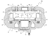
- FIG. 1 is a front view showing a configuration of a disc brake device according to a first embodiment of the present invention.
- FIG. 2 is a left side view showing the configuration of the disc brake device according to the first embodiment of the present invention.
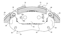
- FIG. 3 is a rear view showing the configuration of the disc brake device according to the first embodiment of the present invention.
- FIG. 4 is a top view showing the configuration of the disc brake device according to the first embodiment of the present invention.
- FIG. 5 is a bottom view showing the configuration of the disc brake device according to the first embodiment of the present invention.
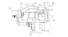
- 6 is a cross-sectional view taken along the line AA in FIG.
- FIG. 7 is a view showing the arrangement of the support with the caliper body removed and the inner brake pads.
- FIG. 8 is a view showing a BB cross section in FIG.
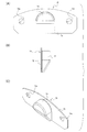
- FIG. 9 is a view showing a cover that can be used in the disc brake device according to this embodiment.
- FIG. 9A is a front view
- FIG. 9B is a left side view
- FIG. 9C is a perspective view.
- FIG. 10 is a diagram for explaining the relationship between the ear portion and the sleeve in the outer brake pad, and is a diagram showing a configuration in which the push anchor is shifted to the push / pull anchor.
- FIG. 11 is a view for explaining the relationship between the ear portion and the sleeve in the outer side brake pad, and is a view showing a configuration in which the pull anchor is shifted to the pull anchor.
- FIG. 10 is a diagram for explaining the relationship between the ear portion and the sleeve in the outer brake pad, and is a view showing a configuration in which the pull anchor is shifted to the pull anchor.
- FIG. 12 is a view showing a configuration of a disc brake device according to a second embodiment of the present invention, and is a view showing a CC cross section when FIG. 1 is used.
- FIG. 13 is a view showing a configuration of a disc brake device according to a second embodiment of the present invention, and is a view showing a BB cross section when FIG. 2 is used.
- FIG. 14 is a front view showing a configuration of an outer brake pad used in the disc brake device according to the second embodiment.
- FIG. 15 is a bottom view showing the configuration of the outer brake pad shown in FIG.
- FIG. 16 is a left side view showing the configuration of the outer brake pad shown in FIG. FIG.
- FIG. 17 is a view for explaining an applied form of the outer brake pad applicable to the disc brake device according to the second embodiment of the present invention.
- FIG. 18 is a front view showing a configuration of a disc brake device of a type using a part of the caliper body as an anchoring element.
- 19 is a cross-sectional view of FIG. 18 corresponding to the BB cross section of FIG.
- FIG. 20 is a view showing the arrangement of the caliper body, the sleeve, and the guide pin during non-braking.
- FIG. 21 is a diagram showing the behavior of the caliper body, the sleeve, and the guide pin at the initial stage of braking, and shows a state where the guide pin on the rotor introduction side is in contact with the inner wall of the sleeve.
- FIG. 22 is a diagram showing the behavior of the caliper body, the sleeve, and the guide pin at the initial stage of braking, and shows a state where the guide pins on the rotor introduction side and the extraction side are in contact with the inner wall of the sleeve.
- FIG. 23 is a diagram showing the behavior of the caliper body and the sleeve during braking, and shows a state in which the contact surface e formed in the notch portion on the rotor turn-in side is in contact with the outer peripheral surface of the sleeve.
- FIG. 24 is a diagram illustrating the behavior of the caliper body and the sleeve during braking. The contact surface e formed in the notch portion on the rotor introduction side contacts the outer peripheral surface of the sleeve, and the rotation on the outer brake pad. A state in which the contact surface c provided on the output ear is in contact with the outer peripheral surface of the sleeve is shown.
- FIG. 25 is a view showing the form of an anti-rattle spring used in the disc brake device according to the embodiment shown in FIGS. 18 and 19, wherein FIG. 25 (A) is a front view, FIG. 25 (B) is a plan view, 25 (C) shows the right side.
- FIG. 26 is a view showing an example of a specific configuration of a pad clip applicable to the disc brake device according to the present invention.
- FIG. 26 (A) is a front view
- FIG. 26 (B) is a plan view
- FIG. C) is a right side view
- FIG. 26D is a perspective view.
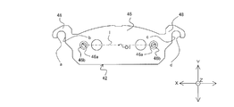
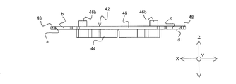
- the disc brake device 10 is configured based on the caliper body 12, the support 24, the inner side brake pad 34, the outer side brake pad 42, and the rotor 60.
- the caliper body 12 has a cylinder part 14, a claw part 16, a center bridge 18, and a side bridge 20.
- the cylinder part 14 is a drive source of the disc brake device 10 according to the first embodiment, and includes a piston 14a and a cylinder 14b for accommodating and projecting the piston 14a.
- the cylinder portion 14 is provided with a guide pin assembly portion 22 for assembling a guide pin 52 which will be described in detail later.
- the guide pin assembly portion 22 is provided so as to be located outside the outer periphery of the rotor 60. This is because the assembled guide pin 52 is positioned outside the outer periphery of the rotor 60 to avoid interference between the rotor 60 and the guide pin 52.
- the claw portion 16 is a reaction force receiver for the pressing force generated by the piston 14a.
- the claw portion 16 is provided with a notch portion 16a (inner peripheral side notch portion) at a position facing the cylinder forming position in the cylinder portion. This is because the inner peripheral machining of the cylinder 14b in the cylinder portion 14 is performed using the notch portion 16a.
- Each block (two blocks in the example shown in this embodiment) constituting the claw portion 16 is formed with a through hole 16b (see FIG. 12) for inserting a bolt.
- the through hole 16b is a step hole, and it is desirable that the bolt head of the bolt 17 used for fastening does not protrude outward.
- the caliper body 12 is disposed in a limited space between the rotor 60 and the wheel inner wall 95, interference with the wheel can be suppressed by reducing the protruding portion from the caliper body 12, and the flat surface It is because it leads to the improvement of aesthetics by formation.
- the cylinder part 14 and the claw part 16 are connected by a center bridge 18 and a side bridge 20 that straddle the outer side of the outer periphery of the rotor 60.
- a through hole 19 is provided in the center of the center bridge 18.
- the side bridge 20 is provided on the turn-in side (I) and the turn-out side (O) of the rotor 60 with the center bridge 18 as a base point.
- the thickness of the center bridge 18 is reduced while braking.
- the opening between the cylinder part 14 and the claw part 16 and the distortion (tilt) in the rotor rotation direction can be suppressed.
- the caliper body 12 can be disposed in the gap even when the gap between the wheel inner wall 95 of the wheel and the outer periphery of the rotor 60 is narrow.
- the caliper body 12 does not fit between the wheel inner wall 95 and the outer periphery of the rotor 60, it is necessary to take measures such as wheel inch up and rotor size down. In such a case, for example, when the wheel is increased in inches, it is necessary to reduce the flatness of the tire, which may cause a deterioration in ride comfort and an increase in cost due to the mounting of a large-diameter wheel. Further, when the size of the rotor is reduced, it is necessary to secure a wide pressing surface when the piston diameter is increased and the same hydraulic pressure is applied to the rotor. This is because when a high pressing force is applied to the rotor by increasing the hydraulic pressure, the spread between the cylinder portion and the claw portion that occurs during braking increases. In addition, when a large-diameter piston is employed, there are concerns that problems such as an increase in weight and deterioration of the touch feeling of the pedal during a brake operation may occur.
- the overall weight of the disc brake device 10 can be reduced, which can contribute to an improvement in the motion performance of the vehicle. .
- a notch portion 21 (outer peripheral side notch portion) formed so as to be hooked on the claw portion 16 is provided.
- the notch portion 21 is provided at a position corresponding to the guide pin assembly portion 22 in the cylinder portion 14. This is to avoid interference between the caliper body 12 and the guide pin guide portion 32 (the sleeve 50 provided in the guide pin guide portion 32 in the present embodiment) in the support 24 for sliding the guide pin 52.
- the notch portion 21 on the claw portion 16 side is provided in a range of a portion corresponding to the outer side of the outer periphery of the rotor 60.
- part becomes small, and the bending in the said connection site
- the support 24 is fixed to the vehicle body and plays a role of slidably supporting the caliper body 12.
- the support 24 is disposed between the cylinder portion 14 and the claw portion 16 in the caliper body 12, that is, in the frame of the caliper body 12.
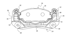
- the support 24 includes at least an anchor 26, a bridge 28, a mounting hole 30, and a guide pin guide portion 32.
- the anchor 26 is disposed on each of the return side (I) and the return side (O) of the rotor 60.
- the anchor 26 supports the inner brake pad 34 and also serves as a torque receiver that receives the force that the inner brake pad 34 tries to rotate around the rotor 60 during braking.
- the bridge 28 is a connecting member that connects the anchor 26 arranged on the turn-in side (I) of the rotor 60 and the anchor 26 arranged on the turn-out side (O).
- the mounting holes 30 are provided in the connecting portions between the anchors 26 and the bridges 28, and are holes for fastening the support 24 to the mounting holes (not shown) provided in the vehicle via bolts (not shown). is there.
- the guide pin guide portion 32 is a through hole or a bag hole provided at the tip of the pair of anchors 26 and located outside the outer periphery of the rotor 60 in the assembled state.
- the guide pin guide portion 32 is a through hole, and a sleeve 50 formed in a bag shape is disposed in the through hole, and the guide pin 52 is configured to slide in the sleeve 50. .
- the support 24 is formed of a light metal such as aluminum
- a steel material such as iron is used for the guide pin 52 that is a sliding member.
- electric corrosion electrochemical corrosion
- the sleeve 50 is disposed at a position where the sliding member comes into contact, and the sleeve 50 is made of the same material as the guide pin 52, so that it is possible to prevent electric corrosion occurring between the two and to reduce the weight.
- the support 24 component member is softer than the guide pin 52 component member, the guide pin guide portion 32 may be worn due to sliding, but the hard sleeve 50 is disposed. According to this, this can be prevented.
- the guide pin 52 is a rod-like member that is assembled to the guide pin assembly portion 22 of the cylinder portion 14 in the caliper body 12 described above. Regarding the assembly, the base end of the guide pin 52 is disposed on the cylinder portion 14 and the distal end is disposed on the claw portion 16 side.
- the length of the guide pin 52 may be such a length as to reach the opposing surface of the rotor 60 in the claw portion 16 in the assembled state.
- the guide pin guide portion 32, the sleeve 50, and the guide pin 52 are arranged so as to be positioned in the notch portion 21 formed in the caliper body 12 in the assembled state.
- the guide pin guide portion 32, the sleeve 50, and the guide pin 52 are all inside the arc formed by connecting the center bridge 18 and the two side bridges 20 in the caliper body 12 (that is, the thickness of the back portion). In the range).
- the inner brake pad 34 is a brake pad that is disposed on the inner side of the rotor 60 and is pressed directly by the piston 14 a provided in the cylinder portion 14.
- the inner brake pad 34 includes a lining 36 that is a friction member that comes into contact with the sliding surface of the rotor 60, and a pressure plate 38 that is a steel plate to which the lining 36 is attached.
- the inner brake pad 34 is held by the anchor 26 of the support 24 and is configured to slide in the axial direction of the rotor 60. For this reason, the end portion of the pressure plate 38 (the end portion located on the turn-in side (I) and the turn-out side (O) of the rotor 60 in the assembled state) has a concave shape formed inside the anchor 26.
- Corresponding convex ears 40 are formed. At the time of assembly, a pad clip 54 is disposed between the anchor 26 and the ear portion 40 to suppress rattling of the inner brake pad 34 and to maintain slidability in the axial direction. (See FIG. 7).
- the outer brake pad 42 is disposed on the outer side of the rotor 60, and is a brake pad that is pressed toward the rotor 60 by the claw 16 by a reaction force caused by the inner brake pad 34 being pressed against the rotor 60.
- the outer brake pad 42 is also composed of a lining 44 and a pressure plate 46, which are friction members.
- the lining 44 is affixed to one surface of the pressure plate 46 that is located on the side of the arrangement surface of the rotor 60 (see, for example, FIGS. 1 and 2) in the assembled state.
- the difference between the inner brake pad 34 and the outer brake pad 42 in the present embodiment is in the form of a pressure plate 46.
- the disc brake device 10 employs a configuration in which the outer brake pad 42 is screwed into the claw portion, that is, fixed by the bolt 17. Therefore, the pressure plate 46 is formed with a female screw hole 46a for bolting (see FIG. 8).
- the formation position of the female screw hole 46 a may be a position corresponding to the through hole 16 b provided in the claw portion 16.
- the outer side brake pad 42 can be fixed to the claw part 16 by the bolt 17 through the through hole 16b.
- the pressure plate 46 of the steel plate is bolted so that the claw part 16 and the pressure plate 46 can be regarded as a single structure.
- the rigidity of the claw portion 16 (caliper body 12) can be improved by using the pressure plate 46 as a strength member.
- the outer brake pad 42 since the outer brake pad 42 is fixed to the claw portion 16, sliding support by the support 24 becomes unnecessary. Therefore, it is not necessary to form the outer frame on the support 24, and the area of the notch 21 in the caliper body 12 provided for preventing interference is suppressed in addition to reducing the manufacturing cost and weight by reducing the size of the support 24. Can also contribute.
- the female screw hole 46a is arranged on the inner side (the inner peripheral side of the rotor 60) with the outer periphery of the rotor 60 as a base point. Further, the female screw hole 46a is arranged within the range of the friction surface in the lining 44 when the outer brake pad 42 is viewed from the front.
- the female screw hole 46a has a straight line l connecting the centers of the two female screw holes 46a in the assembled state, and the center O1 of the cylinder arrangement position of the cylinder 14b provided in the caliper body 12. Arrange to pass through the vicinity.
- the braking torque transmitted from the rotor 60 to the outer brake pad 42 bolted to the claw portion 16 can be transmitted to the caliper body 12 (claw portion 16) without waste. That is, the integrity of the claw portion 16 and the outer brake pad 42 can be enhanced in the tangential direction in which the torque during braking is applied.
- the sleeve 50 and the support 24 are provided. A tangential force can be transmitted to
- the ears 48 formed on the pressure plate 46 are arranged so as to contact the sleeve 50 during braking.
- the ear portion 48 of the outer brake pad 42 contacts the sleeve 50, so that the sleeve 50 serves as an anchor, and the center bridge 18, the side bridge 20, and the claws This is because the load applied to the part 16 can be reduced.
- the guide pin 52 accommodated in the sleeve 50 has a length from the cylinder portion 14 to the opposing surface of the rotor 60 in the claw portion 16.
- the ear portion 48 of the pressure plate 46 in the outer brake pad 42 is a hanger type that covers the sleeve 50 from above and faces the radially inner periphery of the rotor 60. And a torque receiving portion in which a concave notch having an open portion is formed.
- the tip end side of the ear portion 48 abuts on the sleeve 50, and a so-called pulling anchor state is established.
- the proximal end side of the ear portion 48 comes into contact with the sleeve 50 and is in a so-called pushing anchor state. Further, according to such a configuration, the caliper body 12 can be assembled to the support 24 on which the sleeve 50 is disposed after the outer brake pad 42 is assembled to the claw portion 16.
- an axis parallel to a straight line passing through the rotation center O0 of the rotor 60 and the center O1 (cylinder center) of the cylinder arrangement position of the cylinder 14b in plan view is defined as the Y axis.
- a straight line orthogonal to the Y axis is defined as the X axis
- a straight line that intersects the Y axis and the X axis and is parallel to the rotation axis of the rotor 60 is defined as the Z axis.
- the four surfaces of the contact surface a, the contact surface b, the contact surface c, and the contact surface d which are contact surfaces of the ear portion 48 and the sleeve 50, are respectively It is formed to be parallel.
- the ear portion 48 is a torque receiving portion in which a concave notch is formed.
- d is a torque receiving surface.
- the contact surfaces a to d are formed in parallel to the Y axis, more specifically, the surface formed by the Y axis and the Z axis (YZ surface).
- the outer peripheral surface of the sleeve 50 is disposed in parallel with the Z-axis, so that the transmission loss of the braking torque at the time of contact is reduced by adopting such a configuration.
- the shape of the ear portion 48 is such, by adjusting the gap between the ear portion 48 and the sleeve 50, only the push anchor, only the pull anchor, or the push anchor ( Alternatively, it is possible to use only a pull anchor and a pull anchor and a pull anchor (or a pull anchor and a push anchor) during the main braking.
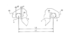
- FIGS. 10 and 11 An example of the relationship between the push-pull anchor and the sleeve is shown in FIGS. 10 and 11, respectively. In the following description, as shown in FIG. 8, the rotation direction of the rotor 60 is assumed to be clockwise (clockwise).
- FIG. 10 shows an example in which the center-to-center distance L2 of the hook part (concave notch) of the ear part 48 is longer than the center-to-center distance L1 of the sleeve 50 (guide pin 52).
- the gap d2 generated between the sleeve 50 and the hook portion of the ear 48 is closer to the gap d2 generated on the end side of the pressure plate than the gap d1 generated on the center side of the pressure plate 46. Becomes larger.
- the sleeve 50 including the caliper body 12 or the guide pin 52 is less bent at the initial stage of braking, the sleeve 50 and the ear portion 48 disposed on the delivery side (O) of the rotor 60 are The gap d1 becomes zero, and the contact surface c comes into contact with the sleeve 50 to be in a pushing anchor state. Thereafter, when the tangential force increases, the gap d2 between the sleeve 50 and the ear portion 48 disposed on the turn-in side (I) of the rotor 60 becomes zero, and the contact surface a and the sleeve 50 come into contact with each other to pull the anchor. It becomes a state. That is, in the case of L1 ⁇ L2, d1 ⁇ d2 is obtained, and the structure reaches from the push anchor to the push / pull anchor state.
- the example shown in FIG. 11 shows an example in which the center distance L2 of the hook portion of the ear 48 is shorter than the center distance L1 of the sleeve 50 (guide pin 52).
- the gap d2 generated between the sleeve 50 and the hook portion of the ear 48 is closer to the gap d2 generated on the end side of the pressure plate than the gap d1 generated on the center side of the pressure plate 46. Becomes smaller.
- the rotor 60 is a rotating plate disposed between the inner brake pad 34 and the outer brake pad 42, and has a sliding surface at a position facing the linings 36 and 44 in each brake pad.
- the rotor 60 is fixed so as to rotate with a wheel (not shown).
- the disc brake device 10 is provided with a cover 70 that covers the notch portion 16a formed in the claw portion 16.
- the cover 70 smoothes the unevenness generated on the outer side surface (front surface) of the caliper body 12 and changes the appearance impression of the caliper body 12.
- the cover 70 includes a base plate 72 and a cover plate 74.
- the base plate 72 is a plate for fixing the cover 70 to the caliper body 12.
- the base plate 72 in the case of this embodiment is disposed between the pressure plate 46 of the outer brake pad 42 and the claw portion 16, and is fastened together by bolts 17 that fix the pressure plate 46 to the claw portion 16.
- the base plate 71 is formed with a fixing hole 72a through which the bolt 17 is inserted.
- the cover plate 74 is a main part of the cover 70, and its shape varies widely. For example, in the case of this embodiment, it is formed so as to be convex with respect to the base plate 72 so as to smooth the step between the pressure plate 46 caused by the notch 16a and the outer side surface of the claw 16. Yes.
- the cover plate 74 formed in a convex shape is inclined along the thin portion of the claw portion 16 so that the convex thickness is reduced toward the direction of the inner diameter side of the rotor 60. It has been. In this way, the notch 16a covers the step formed on the outer side surface of the caliper body 12, and the appearance impression is changed, thereby improving the design of the disc brake device 10 and giving a so-called high-class feeling and individuality. It becomes possible.
- the notch portion 16a is covered by the bolt-fixable cover 70, it is possible to easily give a change or accent to the appearance of the caliper body 12 simply by exchanging it. Moreover, since it is not the structure which covers the caliper body 12 whole, heat dissipation can be kept favorable and brake performance can be maintained favorable. Further, it is lighter than that covering the entire caliper body 12. For this reason, when it sees as the whole vehicle, it leads also to an improvement in a fuel consumption.
- FIG. 12 is a cross-sectional view showing a characteristic configuration of the disc brake device according to the second embodiment. When FIG. 1 is used, it corresponds to a CC cross section.
- FIG. 13 is a cross-sectional view taken along the line BB when FIG. 2 is used.
- the difference between the disc brake device 10a according to the second embodiment and the disc brake device 10 according to the first embodiment lies in the configuration of the outer brake pad 42.
- the pressure plate 46 constituting the outer brake pad 42 is provided with a boss 46b that fits into the through hole 16b formed in the claw portion 16.
- the pressure plate 46 of the outer brake pad 42 according to the second embodiment includes a plate body, a boss 46b, and an ear 48.
- the plate body is an area for attaching the lining 44 described above, and is formed to be slightly larger than the outer shape of the lining 44.
- the boss 46b protrudes from the other surface of the pressure plate 46 opposite to the surface to which the lining 44 is attached, that is, the surface facing the claw portion 16 of the caliper body 12 in the assembled state (for example, (See FIGS. 1 and 2). For this reason, when the pressure plate 46 is viewed from the front, the boss 46 b is provided within the range of the friction surface of the lining 44.
- the bosses 46b are provided in at least a pair (two), and are provided so as not to be positioned on the inner peripheral side of the cylinder 14b in the cylinder portion 14 when viewed from the front in the assembled state (for example, FIGS. 8 and 10). reference).
- the paired bosses 46b are provided at positions corresponding to the claw portions 16 located on the turn-in side (I) of the rotor 60 and the claw portions 16 located on the turn-out side (O) of the rotor 60, respectively. .
- the boss 46b can be fitted into the through hole 16b formed in the claw portion 16, and the claw portion 16 and the pressure plate 46 can be integrated.
- the straight line l connecting the centers of the paired bosses 46b overlaps the cylinder portion 14 with the position overlapping the rotation center O0 of the rotor 60 when the disc brake device 10 with the outer brake pad 42 assembled is viewed from the front.
- An axis parallel to a straight line passing through a position overlapping the center O1 of the cylinder arrangement position of the cylinder 14b formed on the cylinder 14b and parallel to the plate surface of the pressure plate 46 is defined as a Y axis
- the tangent of the rotor 60 to the Y axis When an axis parallel to a straight line orthogonal to the direction (a straight line along the load direction of the tangential force received during braking) is defined as the X axis, the center O1 of the cylinder arrangement position of the cylinder 14b is parallel to the X axis, or It passes through the vicinity (see FIG.
- the boss 46b By providing the boss 46b in such an arrangement, the direction of the tangential force applied to the center of pressing by the piston 14a (actually, the pressing portion by the claw portion 16 that receives a reaction force against pressing) and the straight line l are obtained. Overlap. Therefore, the integrity of the claw portion 16 and the outer brake pad 42 can be improved in the direction in which the tangential force is applied, and the tangential force can be transmitted to the claw portion 16 of the caliper body 12 without loss. Can do. That is, the outer side brake pad 42 can act as a strength member of the caliper body 12.
- the vicinity of the center O1 of the cylinder arrangement position here is an allowable range of the deviation width of the straight line 1 along the Y-axis direction, and is, for example, about the diameter of the boss 46b or the diameter of a female screw hole 46a described later. It can be a range.
- Each of the bosses 46b is formed with a female screw hole 46a along the protruding direction of the boss 46b (in the case of defining the axis, an axis parallel to the axial direction of the rotor 60 (Z axis)). Since the female screw hole 46a is provided in the boss 46b, the boss 46b fitted into the through hole 16b formed in the claw portion 16 is screwed by the bolt 17 and can be stably fastened to the claw portion 16 ( (See FIG. 12). As a result, the pressure plate 46 in the outer brake pad 42 can be regarded as a single body structure with the claw portion 16, and the outer brake pad 42 (pressure plate 46) is used as a strength member and the two notches 16 a are used as two members. The rigidity of the claw part 16 (caliper body 12) divided into blocks can be improved.
- the ear 48 abuts against a guide pin 52 (see a sleeve 50 described in detail later in the second embodiment: see FIG. 6 and the like) during braking, and receives a tangential force with the guide pin 52 and the sleeve 50 as anchors. Take on. For this reason, when the caliper body 12 bends during braking, the ear portion 48 of the outer brake pad 42 abuts on the sleeve 50, and the caliper body 12 can be prevented from bending. For this reason, the tangential force at the time of braking is transmitted to the caliper body 12 and transmitted from the ear portion 48 to the sleeve 50 as a part of the caliper body 12.
- the tangential force is transmitted from the caliper body 12 directly to the base side of the guide pin 52 connected to the support 24 in addition to the transmission from the ear 48 to the sleeve 50. For this reason, the partial wear of the lining 44 due to the inclination of the posture of the caliper body 12 and the distortion of the sleeve 50 (guide pin 52) can be suppressed.
- the guide pin 52 accommodated in the sleeve 50 has a length from the cylinder portion 14 to the opposing surface of the rotor 60 in the claw portion 16. For this reason, when the pressure plate 46 of the outer side brake pad 42 fixed to the opposing surface of the rotor 60 in the claw portion 16 contacts the sleeve 50, the guide pin 52 is disposed therein. Therefore, there is no possibility that the sleeve 50 is damaged such as a dent due to the contact of the ear 48.
- the guide pin 52 (sleeve 50) is disposed on the outer peripheral side of the rotor 60. It is assumed that the disc brake device 10 (10a) is assembled. For this reason, the ear
- a disc brake device having a guide pin that protrudes toward the rotor side on the inner peripheral side of the rotor outer diameter after the support straddles the rotor is also provided.
- the weight of the support is increased, and it is necessary to provide guide pins on the inner side and the outer side of the rotor. It is desirable to employ the disc brake device 10a as in the embodiment.
- the reliability in terms of safety can be further improved compared to the disc brake device 10 according to the first embodiment.
- the outer side brake pad 42a corresponding to the present embodiment is different in the form of the ear 48 from the outer side brake pad 42 described in the above embodiments.
- the ear portion 48 of the outer side brake pad 42 described in each of the above embodiments is a hanger type, whereas the ear portion 48a of the outer side brake pad 42a in this embodiment is a contact surface 49 cut off linearly.
- the contact surface 49 formed on the ear portion 48a is configured in parallel to the Y axis, more specifically, the surface formed by the Y axis and the Z axis (YZ plane), as in the above embodiments. Is done.
- the anchor effect by the sleeve 50 can be obtained at the time of braking since the contact surface 49 with the sleeve 50 is provided.
- the ear portion 48a in this embodiment is a cut-off contact surface 49, it is not possible to obtain an anchor effect by a so-called pull anchor.
- the anchor effect is only due to the pushing anchor against the sleeve 50 located on the delivery side (O) of the rotor 60.
- a thing like this form is employ
- adopted as a form of the pressure plate 46 a plate-formability will improve compared with what was demonstrated in said each embodiment. For this reason, the material cost and weight can be reduced, and the processing cost accompanying simplification of the outer shape can be reduced.
- the claw portion 16 integrated with the outer brake pad 42b by fixing via the bolt 17 is used as a torque receiving element. It is the same as the form. Therefore, portions having the same configuration are denoted by the same reference numerals in the drawings, and detailed description thereof is omitted.
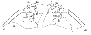
- a specific difference from the disc brake devices 10 and 10a according to the above embodiments is the configuration of the notch 21.
- the notch portion 21 is provided so as to avoid interference between the caliper body 12 and the sleeve 50.
- the contact surfaces e and f are formed on the side wall of the claw portion 16 located on the side bridge 20 side in the notch portion 21 provided in the caliper body 12. (See FIG. 20).
- the contact surface e provided in the notch 21 contacts the sleeve 50 on the turn-in side (I) of the rotor 60, thereby forming a pulling anchor and On the outlet side (O), the contact surface c provided on the ear portion 48b of the pressure plate 46 comes into contact with the sleeve 50, thereby forming a push anchor (see FIG. 20).
- the caliper body 12 fastened to the pressure plate 46 since a part of the caliper body 12 fastened to the pressure plate 46 is used as an anchor element and an anchor effect is exerted, there is no need to use a hanger type with a wide plate width of the ear portion. For this reason, even when the gap with the wheel inner wall 95 is narrow, it is possible to realize the pulling anchor on the turn-in side (I) of the rotor 60. Furthermore, in order to form the contact surfaces e and f in the notch portion 21, by forming the portions in a convex shape, the opening area of the notch portion 21 is substantially reduced. For this reason, the rigidity of the caliper body 12 can be increased.
- the contact surfaces e and f of the caliper body 12 are processed by inserting the cutting tool from the radial direction of the rotor 60 and sliding the inserted cutting tool in the axial direction. can do.
- a notch 21 is provided between the center bridge 18 and the side bridge 20 in the caliper body 12. For this reason, a cutting tool can be inserted using the notch 21.
- the gap between each contact surface and the sleeve 50 is determined as shown in FIG. That is, when the rotation direction of the rotor 60 is clockwise (rotation from right to left in the figure), the gap between the contact surface e provided on the notch 21 on the turn-in side (I) and the sleeve 50. D3 is set to be narrower than the gap D4 between the contact surface c provided on the ear portion 48b on the delivery side (O) and the sleeve 50. Further, in the disc brake device 10b according to the present embodiment, the gaps D1 and D2 between the sleeve 50 and the guide pin 52 are determined so as to satisfy D2> D1 by design.
- an anti-rattle spring is assembled to the disc brake device 10b according to the present embodiment.
- the anti-rattle spring is an element for preventing the caliper body 12 from falling and stabilizing the posture (radial positioning element).
- the anti-rattle spring 80 includes a caliper side engaging portion 82 and a sleeve side engaging portion 88, which are connected by a spring portion 92.
- 25A is a view showing a front form of the anti-rattle spring 80
- FIG. 25B is a plan view
- FIG. 25C is a right side view.
- a clip portion 84 and a load point 86 are provided in the caliper side engaging portion 82 in the anti-rattle spring 80 having the form shown in FIG.
- the clip portion 84 sandwiches a part of the caliper body 12 (in the example shown in FIG. 18, sandwiches the thinned portion of the back portion forming the through hole 19 formed in the center bridge 18. ), An element for stably holding the anti-rattle spring 80 on the caliper body 12.
- the load point 86 in the caliper side engaging portion 82 contacts the inner peripheral side of the caliper body 12 and applies a load in a direction in which the caliper body 12 is lifted (a direction toward the outer peripheral side in the radial direction of the rotor 60).
- the sleeve side engaging portion 88 has a load point 90 that comes into contact with the sleeve 50.
- the load point 90 of the sleeve side engaging portion 88 applies a load in a direction in which the sleeve 50 is pushed down (a direction toward the radially inner side of the rotor).
- the caliper body 12 When the load as described above is applied by the load points 86 and 90, the caliper body 12 is pushed up with the sleeve 50 as a base point on the claw portion 16 side, and the posture can be stabilized. it can. Thereby, the unnecessary rocking
- FIGS. 26A is a diagram showing a front view of the pad clip
- FIG. 26B is a plan view
- FIG. 26C is a right side view
- FIG. 26D is a perspective view. It is a figure which shows a form, respectively.
- the pad clip 100 is arranged such that the outer brake pad 42b (including the caliper body 12 fastened to the outer brake pad 42b) is positioned at the center between the sleeves 50 that are torque receiving portions in the circumferential direction of the rotor 60. While controlling the attitude (circumferential positioning element), it is an element for preventing the wear and wear of the covering portion.
- the pad clip 100 includes a main body plate 102 and a cover plate 106, and both are connected by a spring member 104.
- the main body plate 102 is disposed between the claw portion 16 and the pressure plate 46.
- the outer side brake pad 42 b is fastened to the claw portion 16 by the bolt 17, whereby the pad clip 100 is positioned.
- the cover plate 106 has a hanger shape and is arranged so as to cover the outer peripheral surface of the sleeve 50 from the outer peripheral side of the rotor 60. With such a configuration, contact between the ear portion 48a and the outer peripheral portion of the sleeve 50 can be avoided. As a result, it is possible to suppress wear and abrasion due to electric corrosion between different metals and impact during sliding and braking.
- the spring member 104 positions the outer brake pad 42b arranged between the two sleeves 50 in the circumferential direction. As a result, the circumferential position of the caliper body 12 integrated with the outer brake pad 42b is also stabilized.
- a claw having a cylinder portion 14 disposed on the inner side of the rotor 60 and an inner notch portion (notch portion) 16a disposed on the outer side of the rotor 60 and facing the cylinder placement position.
- the portion 16 is connected to the center bridge 18 by the side bridge 20 disposed on the turn-in side (I) and the turn-out side (O) of the rotor 60 with the center bridge 18 as a base point, and an outer peripheral side cutout portion.
- (Notch part) 21 is exposed to the outside of the caliper body from the caliper body 12 provided between the center bridge 18 and the side bridge 20 and the outer peripheral side notch part (notch part) 21,
- a guide pin guide portion 32 disposed within the thickness range of the back meat constituting the center bridge 18 and the side bridge 20 is provided between the cylinder portion 14 and the claw portion 16.
- a support 24 provided, a guide pin 52 that slides on the guide pin guide portion 32 in the support 24, an inner brake pad 34 and an outer brake pad disposed on the inner side and the outer side of the rotor 60, respectively.
- the guide pin guide portion 32 includes a sleeve 50 made of a member having the same strength as the guide pin 52, and The guide pin 52 is a disc brake device 10 that slides on the inner peripheral side of the sleeve 50.
- the disc brake device 10 having the configuration of [2] above, wherein the guide pin 52 has a length reaching the surface of the claw portion 16 facing the rotor 60 in the sleeve 50.
- the outer brake pad 42 includes a friction member (lining) 44 and a pressure plate 46 screwed into the claw portion 16, and the pressure plate 46 has an ear portion that contacts the sleeve 50 during braking.
- a disc brake device 10 provided with 48.
- the disc brake device 10a having the configuration of the above [3], in which the ear portion 48a has a contact surface 49 with respect to the sleeve 50 located on the delivery side (O) of the rotor 60. Device 10a.
- the disc brake device 10b having the configuration of the above [4], wherein the outer circumferential notch (notch) 21 is located on the turn-in side (I) of the rotor 60.
- a disc brake device 10b having contact surfaces e and f against the sleeve 50 on the side wall.
- the disc brake device 10 having the configuration of [3] above, wherein the ear portion 48 is located on both the turn-in side (I) and the turn-out side (O) of the rotor 60.
- Disc brake device 10 having contact surfaces a, b, c, d with respect to [7]
- the disc brake device 10 having the configuration of any one of [4] to [6], wherein an axis parallel to a straight line passing through the rotation center O0 of the rotor 60 and the center O1 of the cylinder arrangement position is provided.
- the disc brake device 10 in which two or four contact surfaces a, b, c, and d with respect to the sleeve 50 are arranged in parallel to the Y axis when defined as the Y axis.
- the claw portion 16 of the pressure plate 46 is disposed on the surface facing the claw portion 16 for screwing.
- the disc brake device 10a is provided with a boss 46b that can be fitted into a through hole 16b provided in the portion 16.
- a disc brake device 10b having the configuration of any one of [2] to [8], wherein an anti-rattle spring 80 is provided between the caliper body 12 and the sleeve 50.
- Device 10b [10] A disc brake device 10b having any one of the above configurations [3] to [9], wherein a contact portion of the sleeve 50 with the outer brake pad 42b and a contact portion with the caliper body 12 are provided.
- a cover plate 106 covering at least one of the contact portions, and a main body plate 102 interposed between the pressure plate 46 and the claw portion 16 are provided, and the cover plate 106 and the main body plate 102 are connected to a spring member 104.
- the disc brake device 10 having the configuration according to any one of [1] to [10] above, and a cover that fills a step between the inner peripheral notch (notch) 16a and the claw 16 Disc brake device 10 provided with 70.
- the disc brake device 10 having the above-described configuration [11], in which the cover 70 is interposed between the pressure plate 46 of the outer brake pad 42 and the claw portion 16.
- the base plate 72 is provided with a fixing hole 72a that can be fastened to the claw portion 16 together with the outer brake pad 42.
- a disc brake device brake pad (outer side brake pad) 42 having a friction member (lining) 44 and a pressure plate 46 to which the friction member (lining) 44 is affixed.
- the at least two bosses 46b projecting from the surface opposite to the surface on which the friction member (lining) 44 is affixed are disposed on each of the inlet side (I) and outlet side (O) of the rotor 60.
- a torque receiving portion (ear portion) 48 is provided, and a female screw hole 46a used for fixing the pressure plate 46 to the caliper body 12 is formed on the protruding surface of the boss 46b.
- a disc brake device brake pad (outer brake pad) 42 provided along the protruding direction. [15] A disc brake device brake pad (outer side brake pad) 42 having the configuration of [14] above, wherein the boss 46 b is disposed at a position on the inner peripheral side with respect to the outer diameter of the rotor 60.
- the torque receiving portion (ear portion) 48 is a disc brake device brake pad (outer side brake pad) 42 disposed at a position on the outer peripheral side with respect to the outer diameter of the rotor 60.
- a disc brake device brake pad (outer side brake pad) 42 having the configuration of [15] above, wherein the boss 46b has a straight line l connecting the centers of two bosses 46b forming a pair. It is arranged parallel to a straight line along the load direction of the tangential force that is sometimes received, and at a position that overlaps the cylinder center (center of the cylinder arrangement position) O1 in the caliper body 12 or a position that passes the vicinity thereof in the front view in the assembled state.
- a disc brake device brake pad (outer brake pad) 42 having the configuration of [16] above, wherein the torque receiving portion (ear portion) 48 is opened in the inner circumferential direction of the rotor 60.
- a disc brake device brake pad (outer side brake pad) 42 having the configuration of [17] above, wherein opposing surfaces (contact surfaces) a, b, c, d of the concave notches are Discs provided parallel to the Y axis, which are parallel to each other and parallel to a straight line passing through a position overlapping the cylinder center (center of the cylinder arrangement position) O1 and a position overlapping the rotation center O0 of the rotor 60.
- Brake pad for brake device (outer side brake pad) 42 having the configuration of [17] above, wherein opposing surfaces (contact surfaces) a, b, c, d of the concave notches are Discs provided parallel to the Y axis, which are parallel to each other and parallel to a straight line passing through a position overlapping the cylinder center (center of the cylinder arrangement position) O1 and a position overlapping the rotation center O0 of the rotor 60.
- the disc brake device and the disc brake device brake pad of the present invention are not limited to the above-described embodiment, and can be appropriately modified and improved.
- the material, shape, dimensions, number, arrangement location, and the like of each component in the above-described embodiment are arbitrary and are not limited as long as the present invention can be achieved.
- the present application includes a Japanese patent application filed on October 26, 2012 (Japanese Patent Application No. 2012-236574), a Japanese patent application filed on October 26, 2012 (Japanese Patent Application No. 2012-236777), and September 19, 2013. This is based on the Japanese patent application (Japanese Patent Application No. 2013-194028), the contents of which are incorporated herein by reference.
- the disc brake device it is possible to provide a disc brake device that can be mounted in a narrow wheel space while maintaining an appropriate rigidity while achieving weight reduction.
- the disc brake device can be reduced in weight, and the caliper body posture can be ensured during braking and the occurrence of uneven wear of the friction member can be suppressed. It becomes possible.
Landscapes
- Engineering & Computer Science (AREA)
- General Engineering & Computer Science (AREA)
- Mechanical Engineering (AREA)
- Braking Arrangements (AREA)
Abstract
シリンダ部14と、切欠き部16aを有する爪部16とがセンタブリッジ18とサイドブリッジ20とにより接続され、切欠き部21がセンタブリッジ18とサイドブリッジ20との間に設けられたキャリパボディ12と、ガイドピン案内部32がシリンダ部14と爪部16との間に設けられたサポート24と、ガイドピン案内部32に摺動するガイドピン52と、切欠き部16aにおけるロータ60の回入側と回出側のそれぞれにおいて、爪部16におけるロータの対向面に螺合されたアウタ側ブレーキパッド42と、を備える。
Description
本発明は、ディスクブレーキ装置及びディスクブレーキ装置用ブレーキパッドに関する。
ディスクブレーキ装置において、高い制動力を得るためには、大径のロータを採用することが望ましいとされている一方で、ホイールの内径に収容されるディスクブレーキ装置には、その配置に際してスペース的な制限が課せられている。
このような観点から、ディスクブレーキ装置を構成するキャリパボディには、小型化の要請が強い。さらに、車両の運動性能を向上させるため、軽量化といった課題も課せられている。ここで、フローティング型のディスクブレーキ装置は、ロータのインナ側とアウタ側の双方にピストンを備えるオポーズド型のディスクブレーキ装置に比べ、小型、軽量化に適し、廉価に製造することができることで知られている。
フローティング型のディスクブレーキ装置において、特に小型、軽量化を図る目的で提案されているものとして、特許文献1、2に開示されているようなタイプのものが知られている。特許文献1、2に開示されているディスクブレーキ装置は、通常、ロータのインナ側に配置されたピストンによる押圧力を受ける反力受けとなる爪部の役割をアウタ側に配置するブレーキパッドの背板であるプレッシャプレートに代用させた構造を採っている。すなわち、アウタ側ブレーキパッドのプレッシャプレートをそのまま、キャリパボディの一部として固定する構成である。
このような構成のディスクブレーキ装置は、確かに小型、軽量化を図ることができる。しかし、反力受けがプレッシャプレートのみとなるため、キャリパボディの強度不足が懸念される。
また、従来、ロータのアウタ側に配置されていたサポートのアウタブリッジを廃し、装置全体の軽量化を図った構成のフローティング型ディスクブレーキ装置が、特許文献3に開示されている。特許文献3に開示されているディスクブレーキ装置は、従来は、アウタ側に延設されたサポートにガイドされるアウタ側ブレーキパッドのプレッシャプレートが、キャリパボディにおける反力受けである爪部にボルト固定される構成を採っている。このような構成のディスクブレーキ装置では、プレッシャプレートがキャリパボディの剛性を補助する一方で、キャリパボディにおけるブリッジの肉厚が薄いため、制動時にキャリパボディに生ずるチルト量が増え、偏摩耗等が生じるおそれがある。
さらに、特許文献4には、キャリパの安定性とねじれ剛性を高めるために、キャリパの下側縁部を取り囲むフレームを備える構成としたディスクブレーキ装置が開示されている。このような構成のディスクブレーキ装置では、サポートのアウタ側フレームをロータの回入側と回出側とで接続するサポートのアウタ側ブリッジが排除され、軽量化が図られている。そして、アウタ側ブレーキパッドが爪部にバネ支持されることで、制動トルクの一部がキャリパにおける爪部で受けられるようにし、キャリパの縁部を囲むフレームにより、キャリパ全体の剛性が高められるようにしている。
ディスクブレーキ装置の性能を高める手法として、ロータの回出側と回入側における制動トルクの受け方の使い分けを適切に行うことが知られている。特許文献4や、特許文献5のように、サポートのアウタブリッジが廃されたディスクブレーキ装置では、アウタ側ブレーキパッドの制動時のトルクが摺動部材により受けられる構成としている。
また、ディスクブレーキ装置に用いられるブレーキパッドには、ロータのインナ側に配置されるもの(インナ側ブレーキパッド)と、ロータのアウタ側に配置されるもの(アウタ側ブレーキパッド)がある。特に、フローティング型のディスクブレーキ装置では、インナ側ブレーキパッドとアウタ側ブレーキパッドとにおいて、その保持形態を異ならせているものが知られている。
例えば特許文献6に開示されているディスクブレーキ装置では、インナ側ブレーキパッドは、キャリパボディを支持するサポートによって保持する形態を採っている。一方、アウタ側ブレーキパッドは、サポートから延設されているガイドピンの一端に吊下させる保持形態を採っている。
また、特許文献3に開示されているディスクブレーキ装置では、インナ側ブレーキパッドは、キャリパボディのブリッジに設けたレール状のガイドと、サポートに取り付けられた管状のガイドにより保持する形態が採られている。一方、アウタ側ブレーキパッドは、キャリパボディの爪部にボルト固定することで保持する形態が採られている。
これらの特許文献3及び特許文献6に開示されたディスクブレーキ装置に対し、インナ側ブレーキパッドとアウタ側ブレーキパッドの保持形態を同様にしているディスクブレーキ装置が、特許文献7に開示されている。特許文献7に開示されているディスクブレーキ装置では、ロータを跨ぐような形態のサポートを採用し、サポートにおけるロータのインナ側とアウタ側からそれぞれロータ配置側へ向けてガイドピンを突設し、このガイドピンにより、インナ側ブレーキパッドおよびアウタ側ブレーキパッドを保持する形態としている。
上述したように、上記特許文献1、2に開示されているディスクブレーキ装置によれば、キャリパのアウタ側に配置されていた爪部が排除されるため、従来に比べて小型化、軽量化を図ることができる。しかし、アウタ側ブレーキパッドのプレッシャプレートが、ピストンによる押圧に対する反力受けとなるため、制動時に生ずるキャリパの開きが大きくなるおそれがあり、キャリパの剛性不足が懸念される。
また、特許文献3に開示されているディスクブレーキ装置においても、アウタ側ブレーキパッドが爪部にボルト固定されることで、アウタ側に配置されるサポートが不要となり、軽量化を図ることができる。しかし、このような構成とした場合、アウタ側ブレーキパッドの制動トルクを全て爪部で受けることとなる。このため、キャリパのチルト量が増加し、偏摩耗等が生ずることが懸念される。
さらに、特許文献4に開示されているディスクブレーキ装置では、サポートのアウタ側ブリッジの排除により軽量化が図られているが、キャリパ下側縁部全域を囲うフレームが設けられているため、軽量化としての効果が薄い。また、サポートのアウタ側フレームをロータの外周よりも内側に配置しているため、キャリパとの干渉を防ぐための切欠きについても、爪部を大きくえぐるように設ける必要があり、キャリパの剛性を下げている。このため、キャリパのシリンダ部と爪部を接続するブリッジの背肉を厚くすることで、全体の剛性不足を補っているが、このような対応を採った場合には、ロータとホイール内壁との隙間を厚くした背肉分だけ広くする必要が生じてしまう。
そこで本発明では、軽量化を図りつつ適正な剛性を保ち、かつ狭隘な車輪スペースにも搭載可能なディスクブレーキ装置を提供することを第1の目的とする。
また、近年では、車輪を構成するホイールの軽量化の他、デザイン性を重視したものが流行している。このようなホイールを採用した場合、ホイールを構成するスポーク間から、ディスクブレーキ装置のアウタ側外観が視認することができ、そのデザイン性にも需要者の関心が高められている。
また、近年では、車輪を構成するホイールの軽量化の他、デザイン性を重視したものが流行している。このようなホイールを採用した場合、ホイールを構成するスポーク間から、ディスクブレーキ装置のアウタ側外観が視認することができ、そのデザイン性にも需要者の関心が高められている。
このため、フローティング型のディスクブレーキ装置を採用している車両等では、キャリパ全体を被覆し、オポーズド型のディスクブレーキ装置のような外観を得るカバーが提案されている。しかし、キャリパ全体を覆う従来のカバーは、ディスクブレーキ装置全体の重量を増加させることにより、車両としての燃費性能を低下させることとなる。また、汎用性を高めるために組付け性が不安定となっており、走行中に脱落する危険性もある。また、キャリパ全体を覆った場合、制動時に生じる熱を放熱する作用が低下し、ブレーキ性能を低下させるおそれもある。このように、従来のカバーは、機能的でないばかりでなく、環境問題対策(ecology)的にもこれに反する作用を成すものであった。
そこで本発明では、ディスクブレーキ装置の外観デザインを向上させることができ、かつ軽量で組付け安定性が良く、ブレーキ性能の低下を招くおそれの無いことを基本とし、さらには、キャリパボディの剛性を高める作用を担うことのできるディスクブレーキ用カバーを提供することを第2の目的とする。
また、特許文献7に開示されているディスクブレーキ装置におけるブレーキパッドや、特許文献6に開示されているディスクブレーキ装置におけるアウタ側ブレーキパッドでは、サポートに配置されたガイドピンのみにより、制動時の接線力を受ける構成とされている。このような構成とした場合、キャリパボディの姿勢が傾斜するおそれは無いが、アウタ側ブレーキパッドの接線力は、ガイドピンの先端側に負荷されることとなる。このため、制動時に負荷される接線力が高い場合には、ガイドピンの歪みが大きくなり、ライニングに偏摩耗を生じさせるおそれがある。さらに、ガイドピンの歪みが塑性的に生じた場合には、キャリパボディの摺動性が悪化し、ブレーキ特性にも影響を及ぼすこととなってしまう。
また、特許文献3に開示されているディスクブレーキ装置では、キャリパボディの爪により、制動時の接線力を受ける構成としている。このような構成とした場合、制動時の接線力が高くなると、キャリパボディの姿勢の傾きが大きくなり、ライニングに偏摩耗を生じさせ易くなるという問題がある。
これらの問題を解決するべく、特許文献6、7に開示されているような場合には、ガイドピンの直径を太くすることで剛性を高め、特許文献3に開示されているような場合には、キャリパボディの全体的な肉厚を増加させることで剛性を高めるという手段を採ることが考えられる。しかし、いずれの手段であっても、各要素の剛性を高めるためには、ディスクブレーキ装置全体の重量の増加を伴うこととなり、車両の燃料消費特性や、運動性能を悪化させる他、ディスクブレーキ装置の大型化による取り付け汎用性の低下も懸念されることとなる。
そこで本発明では、ディスクブレーキ装置の軽量化を実現しつつ、制動時におけるキャリパボディの姿勢の安定性を確保し、摩擦部材の偏摩耗の発生を抑制することのできるディスクブレーキ装置用ブレーキパッドを提供することを第3の目的とする。
本発明の上記第1の目的は、下記(1)~(11)の構成により達成される。
(1) ロータのインナ側に配置されたシリンダ部と、前記ロータのアウタ側に配置されてシリンダ配置位置と対向する位置に内周側切欠き部を有する爪部とが、センタブリッジと当該センタブリッジを基点として前記ロータの回入側および回出側に配置されたサイドブリッジとにより接続され、外周側切欠き部が、前記センタブリッジと前記サイドブリッジとの間に設けられたキャリパボディと、前記外周側切欠き部からキャリパボディ外部に露出し、前記センタブリッジおよび前記サイドブリッジを構成する背肉の厚みの範囲内に配置されるガイドピン案内部が、前記シリンダ部と前記爪部との間に設けられたサポートと、前記サポートにおける前記ガイドピン案内部に摺動するガイドピンと、前記ロータのインナ側およびアウタ側にそれぞれ配置されるインナ側ブレーキパッドおよびアウタ側ブレーキパッドと、備え、前記アウタ側ブレーキパッドは、前記内周側切欠き部における前記ロータの回入側と回出側のそれぞれにおいて、前記爪部の前記ロータの対向面に螺合されているディスクブレーキ装置。
(1) ロータのインナ側に配置されたシリンダ部と、前記ロータのアウタ側に配置されてシリンダ配置位置と対向する位置に内周側切欠き部を有する爪部とが、センタブリッジと当該センタブリッジを基点として前記ロータの回入側および回出側に配置されたサイドブリッジとにより接続され、外周側切欠き部が、前記センタブリッジと前記サイドブリッジとの間に設けられたキャリパボディと、前記外周側切欠き部からキャリパボディ外部に露出し、前記センタブリッジおよび前記サイドブリッジを構成する背肉の厚みの範囲内に配置されるガイドピン案内部が、前記シリンダ部と前記爪部との間に設けられたサポートと、前記サポートにおける前記ガイドピン案内部に摺動するガイドピンと、前記ロータのインナ側およびアウタ側にそれぞれ配置されるインナ側ブレーキパッドおよびアウタ側ブレーキパッドと、備え、前記アウタ側ブレーキパッドは、前記内周側切欠き部における前記ロータの回入側と回出側のそれぞれにおいて、前記爪部の前記ロータの対向面に螺合されているディスクブレーキ装置。
(2) 上記(1)の構成を有するディスクブレーキ装置であって、前記ガイドピン案内部には、前記ガイドピンと同様な強度を有する部材により構成されたスリーブが備えられ、前記ガイドピンは、前記スリーブの内周側を摺動するディスクブレーキ装置。
このような構成とすることによれば、ガイドピン構成部材とサポート構成部材とが異なる材質の部材により構成された場合であっても、ガイドピンの摺動面は、同様な強度を有する部材により構成されたスリーブの内周面となる。このため、摺動面に電蝕(電気科学的腐食)や傷などが生じ、摺動性の悪化を招くおそれが無く、いずれか一方の部材(軟らかい部材により構成されている側)の摩滅が進行し易くなるというおそれも無い。
(3) 上記(2)の構成を有するディスクブレーキ装置であって、前記ガイドピンは、前記スリーブ内において、前記爪部における前記ロータとの対向面に至る長さを有し、前記アウタ側ブレーキパッドは、摩擦部材と前記爪部に螺合されるプレッシャプレートとを有し、前記プレッシャプレートには、制動時に前記スリーブに当接する耳部が設けられているディスクブレーキ装置。
このような構成とすることによれば、キャリパが撓むことによりチルト量が増加した際には、アウタ側ブレーキパッドからの接線力をスリーブ(スリーブ内に配置されたガイドピン)が受けることとなり、チルト量の増大による偏摩耗の発生等を防ぐことが可能となる。
(4) 上記(3)の構成を有するディスクブレーキ装置であって、前記耳部は、前記ロータの回出側に位置する前記スリーブに対する当接面を有するディスクブレーキ装置。
このような構成とした場合には、制動時の接線力が大きくなった際に、スリーブに対して耳部は、押しアンカ状態となる。
(5) 上記(4)の構成を有するディスクブレーキ装置であって、前記外周側切欠き部は、前記ロータの回入側に位置する前記サイドブリッジ側の側壁に、前記スリーブに対する当接面を有するディスクブレーキ装置。
このような構成とした場合には、制動時の接線力に対し、サイドブリッジに設けた当接面が引きアンカ状態となり、アウタ側ブレーキパッドの耳部が、押しアンカ状態となる。
(6) 上記(3)の構成を有するディスクブレーキ装置であって、前記耳部は、前記ロータの回入側および回出側の双方に位置する前記スリーブに対する当接面を有するディスクブレーキ装置。
このような構成とした場合には、制動時の接線力が大きくなった際に、スリーブに対して耳部は、押し、引き、両方でアンカ作用を得ることができる。
(7) 上記(4)~(6)の何れかの構成を有するディスクブレーキ装置であって、前記ロータの回転中心と前記シリンダ配置位置の中心とを通る直線に平行な軸をY軸と定めた場合に、前記スリーブに対する2面または4面の前記当接面がそれぞれ平行で、かつ前記Y軸に平行に配置されているディスクブレーキ装置。
このような構成とすることによれば、プレッシャプレートからスリーブに対する接線力の伝達ロスが少なくなる。
(8) 上記(3)~(7)の何れかの構成を有するディスクブレーキ装置であって、前記プレッシャプレートにおける前記爪部との対向面側には、螺合のために前記爪部に設けられた貫通孔に嵌入可能なボスが設けられているディスクブレーキ装置。
このような構成とした場合には、螺合のために設けたボルトが仮に脱落した場合であっても、アウタ側ブレーキパッドは、ボスによる引っ掛かりにより保持され、脱落するおそれが無い。
(9) 上記(2)~(8)の何れかの構成を有するディスクブレーキ装置であって、前記キャリパボディと、前記スリーブとの間に、アンチラトルスプリングが設けられたディスクブレーキ装置。
このような構成とした場合には、アンチラトルスプリングが設けられることにより、キャリパボディのガタツキと共に倒れ込みも抑制することができる。このため、ラトル音を抑制することができると共に、キャリパボディの姿勢安定化に伴い、ライニングの片摩耗等を抑制し、安定した制動性能を発揮することが可能となる。
(10) 上記(3)~(9)の何れかの構成を有するディスクブレーキ装置であって、前記スリーブにおける前記アウタ側ブレーキパッドとの接触部および前記キャリパボディとの接触部のうち少なくとも一方の接触部を覆うカバープレートと、前記プレッシャプレートと前記爪部との間に介在される本体プレートとを備え、前記カバープレートと前記本体プレートとをバネ部材で接続するパッドクリップが設けられたディスクブレーキ装置。
このような構成とすることによれば、異金属間の接触による電蝕や、摺動、衝撃等による摩耗や摩滅を抑制することが可能となる。
(11) 上記(1)~(10)の何れかの構成を有するディスクブレーキ装置であって、前記内周側切欠き部と前記爪部との段差を埋めるカバーが設けられたディスクブレーキ装置。
このような構成とした場合には、ディスクブレーキ装置における外観のデザイン性を向上させることができる。
また、本発明の上記第2の目的は、下記(12)~(13)の構成により達成される。
(12) 上記(11)の構成を備えたディスクブレーキ装置であって、前記カバーが、前記アウタ側ブレーキパッドのプレッシャプレートと、前記爪部との間に介在されるベースプレートと、前記爪部に形成された前記内周側切欠き部を介してアウタ側に露出するカバープレートと、を有するディスクブレーキ装置。
(12) 上記(11)の構成を備えたディスクブレーキ装置であって、前記カバーが、前記アウタ側ブレーキパッドのプレッシャプレートと、前記爪部との間に介在されるベースプレートと、前記爪部に形成された前記内周側切欠き部を介してアウタ側に露出するカバープレートと、を有するディスクブレーキ装置。
このような構成とすることによれば、ディスクブレーキ装置の外観デザインを向上させることができ、かつ軽量で組付け安定性が良く、ブレーキ性能の低下を招くおそれが無い。また、カバーによりキャリパボディの剛性を高めることもできる。
(13) 上記(12)の構成を有するディスクブレーキ装置であって、前記ベースプレートには、前記アウタ側ブレーキパッドと共に前記爪部に共締め可能とするための固定孔が設けられたディスクブレーキ装置。
このような構成とした場合には、キャリパに対するカバーの組付け状態を、より確実なものとすることが可能となる。
また、本発明の上記第3の目的は、下記(14)~(18)の構成により達成される。
(14) 摩擦部材と前記摩擦部材が貼付されるプレッシャプレートとを有するディスクブレーキ装置用ブレーキパッドであって、前記プレッシャプレートには、前記摩擦部材を貼付した面とは反対側の面に突出する、少なくとも2つのボスと、ロータの回入側と回出側のそれぞれに配置されたトルク受け部とが設けられ、前記ボスの突出面には、キャリパボディに対して前記プレッシャプレートを固定するために用いられる雌ネジ穴が、当該ボスの突出方向に沿って設けられているディスクブレーキ装置用ブレーキパッド。
(14) 摩擦部材と前記摩擦部材が貼付されるプレッシャプレートとを有するディスクブレーキ装置用ブレーキパッドであって、前記プレッシャプレートには、前記摩擦部材を貼付した面とは反対側の面に突出する、少なくとも2つのボスと、ロータの回入側と回出側のそれぞれに配置されたトルク受け部とが設けられ、前記ボスの突出面には、キャリパボディに対して前記プレッシャプレートを固定するために用いられる雌ネジ穴が、当該ボスの突出方向に沿って設けられているディスクブレーキ装置用ブレーキパッド。
(15) 上記(14)の構成を備えたディスクブレーキ装置用ブレーキパッドであって、前記ボスは、ロータの外径に対して内周側となる位置に配置され、前記トルク受け部は、前記ロータの外径に対して外周側となる位置に配置されているディスクブレーキ装置用ブレーキパッド。
このような構成とすることにより、プレッシャプレートのボスは、制動時に接線力が負荷される範囲に配置されることとなり、組付け状態においては、接線力をロス無くキャリパボディへ伝達することが可能となる。一方、プレッシャプレートのトルク受け部をロータ外径に対して外周側へ配置することによれば、ディスクブレーキ装置においてアンカとなるサポートやガイドピン等を、ロータのアウタ側側面にまで配置する必要性が無くなる。よって、ディスクブレーキ装置全体の軽量化を図ることができる。また、摩擦部材よりも外周側にプレッシャプレートのトルク受け部が配置されることにより、アンカとなるサポートやガイドピン等に負荷される接線力を低下させることができる。
(16) 上記(15)の構成を備えたディスクブレーキ装置用ブレーキパッドであって、前記ボスは、対を成す2つのボスの中心を結ぶ直線が、制動時に受ける接線力の負荷方向に沿う直線に平行で、かつ組み付け状態の正面視においてキャリパボディにおけるシリンダ中心に重なる位置、またはその近傍を通過する位置に配置されているディスクブレーキ装置用ブレーキパッド。
このような構成とすることにより、制動時に負荷される接線力のキャリパボディへの伝達ロスを最小限に抑えることができる。
(17) 上記(14)~(16)の何れかの構成を備えたディスクブレーキ装置用ブレーキパッドであって、前記トルク受け部には、前記ロータの内周方向に開口を有する凹状の切欠きが設けられ、前記凹状の切欠きにおける対向面がトルク受け面とされたディスクブレーキ装置用ブレーキパッド。
このような構成とすることにより、凹状の切欠き内に、アンカが配置されることとなる。また、ロータの回転方向を問わず、アンカに対して押し、あるいは引きにより、接線力を伝達することが可能となる。また、ブレーキパッドをキャリパボディへ締結固定した後に、ロータの外周側からキャリパボディをかぶせるように、サポートへ組付けることが可能となる。
(18) 上記(17)の構成を備えたディスクブレーキ装置用ブレーキパッドであって、前記凹状の切欠きにおける対向面は、それぞれ平行で、かつ前記シリンダ中心に重なる位置と前記ロータの回転中心に重なる位置を通る直線に平行な直線であるY軸に平行に設けられているディスクブレーキ装置用ブレーキパッド。
このような構成とすることにより、制動時に受けた接線力をロス無くガイドピンやサポート等のアンカへ伝達することができる。よって、トルク受け面の滑りが発生することにより、キャリパボディの姿勢が傾いたり、摩擦部材に偏摩耗が生じたりするおそれがない。
以下、本発明のディスクブレーキ装置及びディスクブレーキ装置用ブレーキパッドに係る実施の形態について、図面を参照しつつ詳細に説明する。
まず、図1から図9を主に参照して、本発明のディスクブレーキ装置に係る第1の実施形態について説明する。
まず、図1から図9を主に参照して、本発明のディスクブレーキ装置に係る第1の実施形態について説明する。
本第1の実施形態に係るディスクブレーキ装置10は、キャリパボディ12、サポート24、インナ側ブレーキパッド34、アウタ側ブレーキパッド42、およびロータ60を基本として構成されている。
キャリパボディ12は、シリンダ部14と爪部16、センタブリッジ18、およびサイドブリッジ20を有する。シリンダ部14は、本第1の実施形態に係るディスクブレーキ装置10の駆動源であり、ピストン14aと、ピストン14aを収容および突出させるためのシリンダ14bとを有する。また、シリンダ部14には、詳細を後述するガイドピン52を組付けるためのガイドピン組付け部22が設けられている。ガイドピン組付け部22は、ロータ60の外周よりも外側に位置するように設けられている。組付けられたガイドピン52をロータ60の外周よりも外側に位置させ、ロータ60とガイドピン52の干渉を避けるためである。
爪部16は、ピストン14aによって生ずる押圧力に対する反力受けである。爪部16には、シリンダ部14におけるシリンダ形成位置と対向する位置に、切欠き部16a(内周側切欠き部)が設けられている。切欠き部16aを利用して、シリンダ部14におけるシリンダ14bの内周加工が行われるからである。爪部16を構成する各ブロック(本実施形態に示す例では2つのブロック)には、それぞれボルトを挿通させるための貫通孔16b(図12参照)が形成されている。貫通孔16bは、段孔とされ、締結に用いられるボルト17のボルト頭が外部に突出しない形態とすることが望ましい。キャリパボディ12は、ロータ60とホイール内壁95との限られたスペースに配置されるため、キャリパボディ12からの突出部位を減らすことにより、ホイールとの干渉を抑制することができると共に、フラット面の形成による美観の向上にも繋がるからである。
シリンダ部14と爪部16とは、ロータ60の外周よりも外側を跨ぐセンタブリッジ18とサイドブリッジ20により接続されている。本第1の実施形態に係るディスクブレーキ装置10では、センタブリッジ18の中央に、貫通孔19が設けられている。貫通孔19を設けることにより、ブレーキパッド(即ち、インナ側ブレーキパッド34およびアウタ側ブレーキパッド42)におけるライニング36,44の減り具合の視認を容易に行うことが可能となると共に、制動時に生ずる熱の放熱にも寄与させることができる。サイドブリッジ20は、センタブリッジ18を基点として、ロータ60の回入側(I)と回出側(O)にそれぞれ設けられる。サイドブリッジ20を設けることによりキャリパボディ12は、平面視で枠型のフレームを有する構造となる。このため、キャリパボディ12の剛性を高めることができる。
従って、鋳鉄よりも軟質なアルミニウム(アルミニウムを主体とした合金を含む)などによりキャリパボディ12を構成する場合であっても、センタブリッジ18の肉厚(いわゆる背肉)を薄くしつつ、制動時に生ずるシリンダ部14と爪部16との間の開きや、ロータ回転方向への歪み(チルト)を抑制することができる。センタブリッジ18やサイドブリッジ20の肉厚を薄くすることにより、車輪のホイール内壁95とロータ60の外周との隙間が狭い場合であっても、その隙間にキャリパボディ12を配置することができる。
ホイール内壁95とロータ60の外周の間にキャリパボディ12が収まらない場合、ホイールのインチアップや、ロータのサイズダウンといった対策を採る必要が生ずる。そうした場合、例えばホイールのインチアップを図ると、タイヤの偏平を小さくする必要が生じ、乗り心地の悪化を招いたり、大径ホイールの装着によるコストアップが懸念される。また、ロータのサイズダウンを図った場合には、ピストン径を大きくし、ロータに対して同じ液圧を付与した際に、広い押圧面を確保する必要が生ずる。液圧を高めることによりロータに対して高い押圧力を付与するようにした場合には、制動時に生ずるシリンダ部と爪部との間の広がりが大きくなってしまうためである。また、大径のピストンを採用する場合には、重量の増大や、ブレーキ操作時におけるペダルのタッチフィーリングの悪化等の問題が生ずることが懸念される。
また、上記のような構成とし、キャリパボディ12をアルミニウム等の軽量部材により構成することにより、ディスクブレーキ装置10全体の軽量化を図ることができ、車両の運動性能向上にも寄与することができる。
センタブリッジ18とサイドブリッジ20との間にはそれぞれ、爪部16に掛かるように形成された切欠き部21(外周側切欠き部)が設けられている。切欠き部21は、シリンダ部14におけるガイドピン組付け部22に対応する位置に設けられている。ガイドピン52を摺動させるためのサポート24におけるガイドピン案内部32(本実施形態においてはガイドピン案内部32に設けられたスリーブ50)と、キャリパボディ12との干渉を避けるためである。
また、爪部16側における切欠き部21は、ロータ60の外周よりも外側にあたる部位の範囲で設けられている。爪部16においてロータ60の外周よりも内側の範囲にまで切欠き部21を広げた場合、サイドブリッジ20に接続された爪部16の構成部位とセンタブリッジ18に接続された爪部16の構成部位との連結部位が小さくなり、当該連結部位での撓みが生じる。このため、サイドブリッジ20の剛性によりセンタブリッジ18の撓みを抑制するという効果が薄らぎ、キャリパボディ12の開きや捻れを抑制するために、センタブリッジ18の肉厚を厚くするという手段を採る必要が生じることとなる。これに対し、切欠き部21の範囲をロータ60の外周よりも外側にあたる部位といった最小限の範囲に抑えることにより、キャリパボディ12全体としての剛性を高めることができると共に、捻れや開きに関する力の分散を図ることができる。
サポート24は、車体に固定され、キャリパボディ12を摺動自在に支持する役割を担う。本実施形態においてサポート24は、キャリパボディ12におけるシリンダ部14と爪部16との間、すなわちキャリパボディ12のフレーム内に配置されている。
サポート24には、少なくとも、アンカ26と、ブリッジ28、取り付け孔30、およびガイドピン案内部32が備えられている。アンカ26は、ロータ60の回入側(I)と回出側(O)のそれぞれに配置されている。本実施形態において、アンカ26は、インナ側ブレーキパッド34を支持すると共に、インナ側ブレーキパッド34が制動時に、ロータ60の回転に供回りしようとする力を受けとめるトルク受けとしての役割を担う。
ブリッジ28は、ロータ60の回入側(I)に配置されるアンカ26と回出側(O)に配置されるアンカ26とを接続する接続部材である。取り付け孔30は、各アンカ26とブリッジ28との接続部に設けられ、車両に設けられた取り付け穴(不図示)に対してボルト(不図示)を介してサポート24を締結するための孔である。
ガイドピン案内部32は、対を成すアンカ26の先端であって、組付け状態においてはロータ60の外周よりも外側となる位置に設けられた貫通孔、あるいは袋穴である。本実施形態では、ガイドピン案内部32を貫通孔とし、当該貫通孔に袋状に形成したスリーブ50を配置する構成とし、当該スリーブ50内にガイドピン52を摺動させるように構成している。
ディスクブレーキ装置10の軽量化を図るために、サポート24がアルミニウム等の軽量金属で形成された場合であっても、摺動部材であるガイドピン52には、鉄などの鋼材が採用される。こうした場合、両者の間には構成材料の違いから、電蝕(電気科学的腐食)が生じ、摺動性能の悪化を招くおそれがある。このため、摺動部材が接触する箇所にスリーブ50を配置し、当該スリーブ50をガイドピン52と同質部材により構成することで、両者の間に生じる電蝕を防ぐことができ、かつ軽量化も図ることができる。また、サポート24構成部材がガイドピン52の構成部材よりも軟質である場合には、摺動に起因してガイドピン案内部32が摩耗するおそれがあるが、硬質のスリーブ50を配置することによれば、これを防ぐことができる。
なお、ガイドピン52は、上述したキャリパボディ12におけるシリンダ部14のガイドピン組付け部22に組付けられる棒状部材である。組付けに関しては、ガイドピン52の基端がシリンダ部14に配置され、先端が爪部16側に配置されるようにする。ここで、ガイドピン52の長さは、組付け状態において爪部16におけるロータ60の対向面に至る程度の長さとすれば良い。
ここで、ガイドピン案内部32、スリーブ50、およびガイドピン52は、組付け状態においてキャリパボディ12に形成された切欠き部21に位置するように配置されている。このような構成とすることで、ロータ60の外周よりも外側に配置されることとなるガイドピン案内部32、スリーブ50、およびガイドピン52が、キャリパボディ12と干渉することを防ぐことができる。なお、ガイドピン案内部32、スリーブ50、およびガイドピン52は、いずれもキャリパボディ12におけるセンタブリッジ18と2つのサイドブリッジ20を結ぶことで構成される円弧の内側(すなわち、背肉部の厚みの範囲内)となるように配置構成されている。このような構成とすることで、キャリパボディ12が収容可能な領域であれば、ガイドピン案内部32等がホイール等と干渉することが無いからである。
インナ側ブレーキパッド34は、ロータ60のインナ側に配置され、シリンダ部14に備えられたピストン14aにより直接押圧されるブレーキパッドである。インナ側ブレーキパッド34は、ロータ60の摺動面に当接する摩擦部材であるライニング36と、ライニング36が貼付される鋼板であるプレッシャプレート38とから構成されている。インナ側ブレーキパッド34は、サポート24のアンカ26に保持され、ロータ60の軸方向へ摺動する構成を採る。このため、プレッシャプレート38の端部(組付け状態でロータ60の回入側(I)と回出側(O)に位置する端部)には、アンカ26の内側に形成された凹形状に対応する凸状の耳部40が形成されている。なお、組付け時においては、アンカ26と耳部40との間に、インナ側ブレーキパッド34のガタつきを抑えると共に軸方向への摺動性を保つためのパッドクリップ54が配置されることとなる(図7参照)。
アウタ側ブレーキパッド42は、ロータ60のアウタ側に配置され、インナ側ブレーキパッド34がロータ60に押し付けられることによる反力で、爪部16によりロータ60側へ押圧されるブレーキパッドである。アウタ側ブレーキパッド42も、インナ側ブレーキパッド34と同様に、摩擦部材であるライニング44とプレッシャプレート46から構成されている。ライニング44は、プレッシャプレート46における一方の面であって、組付状態においては、ロータ60(例えば図1、図2参照)の配置面側に位置する面に貼付されている。本実施形態におけるインナ側ブレーキパッド34とアウタ側ブレーキパッド42との違いは、プレッシャプレート46の形態にある。本第1の実施形態に係るディスクブレーキ装置10では、アウタ側ブレーキパッド42を爪部に螺合、すなわちボルト17により固定する構成を採っている。このため、プレッシャプレート46には、ボルト締めするための雌ネジ穴46aが形成されている(図8参照)。
雌ネジ穴46aの形成位置は、爪部16に設けた貫通孔16bに対応する位置とすると良い。これにより、貫通孔16bを介してボルト17によって、アウタ側ブレーキパッド42を爪部16に固定することができる。切欠き部16aにより2つのブロックに分割された爪部16におけるそれぞれのブロックにおいて、鋼板のプレッシャプレート46がボルト締めされることにより、爪部16とプレッシャプレート46を一塊の構造体とみなすことができ、プレッシャプレート46を強度メンバとして爪部16(キャリパボディ12)の剛性を向上させることができる。また、アウタ側ブレーキパッド42が爪部16に固定されることにより、サポート24による摺動保持が不要となる。よって、サポート24にアウタ側フレームを形成する必要が無く、サポート24の小型化による製造コストの削減、および軽量化の他、干渉防止のために設けるキャリパボディ12における切欠き部21の面積を抑制することにも寄与することができる。
また、雌ネジ穴46aは、ロータ60を基準とした場合には、ロータ60の外周を基点として、その内側(ロータ60の内周側)に配置される。さらに、雌ネジ穴46aは、アウタ側ブレーキパッド42を正面から見た場合、ライニング44における摩擦面の範囲内に配置される構成とする。
また、図8に示すように、雌ネジ穴46aは、組付け状態において、2つの雌ネジ穴46aの中心を繋ぐ直線lが、キャリパボディ12に設けられたシリンダ14bのシリンダ配置位置の中心O1近傍を通るように配置する。このような構成とすることにより、ロータ60から爪部16にボルト固定されたアウタ側ブレーキパッド42に伝達された制動トルクを無駄なく、キャリパボディ12(爪部16)に伝達することができる。すなわち、制動時のトルクが負荷される接線方向に対して、爪部16とアウタ側ブレーキパッド42との一体性を高めることができ、キャリパボディ12の構成の一部として、スリーブ50およびサポート24へ、接線力を伝達することができる。
プレッシャプレート46に形成されている耳部48は、制動時に、スリーブ50に当接する配置形態とすることが望ましい。制動時にキャリパボディ12に撓みが生じた際、アウタ側ブレーキパッド42の耳部48がスリーブ50に当接することで、スリーブ50がアンカとしての役割を果たし、センタブリッジ18やサイドブリッジ20、および爪部16に掛かる負荷を軽減することができるからである。ここで、スリーブ50内に収容されているガイドピン52は上述したように、シリンダ部14を基点として、爪部16におけるロータ60の対向面に至る長さを持つ。このため、爪部16におけるロータ60の対向面に固定されたアウタ側ブレーキパッド42のプレッシャプレート46がスリーブ50に当接する際には、その内部にガイドピン52が配置されていることとなる。よって、耳部48の当接によりスリーブ50が凹み等の損傷を受けるおそれは無い。
本第1の実施形態に係るアウタ側ブレーキパッド42におけるプレッシャプレート46の耳部48は、図8に示すように、スリーブ50を上方から覆うハンガ型とし、ロータ60の半径方向内周側に向けた開口部を持つ凹状の切欠きが形成されたトルク受け部である。耳部48がこのような形態とされた場合、ロータ60の回入側(I)に位置する耳部48では、耳部48の先端側がスリーブ50に当接し、いわゆる引きアンカ状態となる。一方で、ロータ60の回出側(O)に位置する耳部48では、耳部48の基端側がスリーブ50に当接し、いわゆる押しアンカ状態となる。また、このような形態によれば、アウタ側ブレーキパッド42が爪部16に組み付けられた後、スリーブ50が配置されたサポート24に、キャリパボディ12を組付けることができる。
本第1の実施形態では図8に示すように、平面視で、ロータ60の回転中心O0とシリンダ14bのシリンダ配置位置の中心O1(シリンダ中心)とを通る直線に平行な軸をY軸と定める。また、図中Y軸に直交する直線をX軸と定め、Y軸、X軸と交差し、ロータ60の回転軸に平行な直線をZ軸と定める。
本実施形態のこのような環境下においては、耳部48とスリーブ50との当接面である当接面a、当接面b、当接面c、当接面dの4面は、それぞれ平行となるように形成されている。また、耳部48は、凹状の切欠きが形成されたトルク受け部であり、この凹状の切欠きにおける対向面である当接面a及び当接面bと、当接面c及び当接面dとがトルク受け面とされている。そして、各当接面a~dは、Y軸、より具体的にはY軸とZ軸の成す面(YZ面)と平行に形成されることとなる。スリーブ50における外周面がZ軸に平行に配置されるため、このような構成とすることにより、当接時における制動トルクの伝達ロスが少なくなるからである。なお、耳部48の形態をこのようなものとする場合、耳部48とスリーブ50との間の隙間を調整することにより、押しアンカのみ、引きアンカのみ、あるいは、制動初期時は押しアンカ(または引きアンカ)のみで、本制動時には押しアンカと引きアンカ(または引きアンカと押しアンカ)となるように構成することもできる。押し引きアンカとスリーブとの関係については、図10及び図11にそれぞれ一例を示す。なお、以下の説明は、図8に示すようにロータ60の回転方向を時計回り(右回り)と想定した際の説明である。
図10に示す例は、耳部48のフック部分(凹状の切欠き)の中心間距離L2が、スリーブ50(ガイドピン52)の中心間距離L1よりも長い場合の例を示すものである。このような構成とした場合、スリーブ50と耳部48におけるフック部分との間に生ずる隙間が、プレッシャプレート46の中心側に生じる隙間d1よりも、プレッシャプレートの端部側に生じる隙間d2の方が大きくなる。このため、制動初期時であって、キャリパボディ12あるいはガイドピン52を含むスリーブ50の撓みが少ない場合には、ロータ60の回出側(O)に配置されたスリーブ50と耳部48との隙間d1がゼロとなり、当接面cがスリーブ50と接触して押しアンカ状態となる。その後、接線力が高まった場合、ロータ60の回入側(I)に配置されたスリーブ50と耳部48との隙間d2がゼロとなり、当接面aとスリーブ50とが接触して引きアンカ状態となる。つまり、L1<L2とした場合には、d1<d2となり、押しアンカから押し引きアンカの状態に至る構成となる。
一方、図11に示す例は、耳部48のフック部分の中心間距離L2が、スリーブ50(ガイドピン52)の中心間距離L1よりも短い場合の例を示すものである。このような構成とした場合、スリーブ50と耳部48におけるフック部分との間に生ずる隙間が、プレッシャプレート46の中心側に生じる隙間d1よりも、プレッシャプレートの端部側に生じる隙間d2の方が小さくなる。このため、制動初期時であって、キャリパボディ12あるいはガイドピン52を含むスリーブ50の撓みが少ない場合には、ロータ60の回入側(I)に配置されたスリーブ50と耳部48との隙間d2がゼロとなり、当接面aがスリーブ50と接触して引きアンカ状態となる。その後、接線力が高まった場合、ロータ60の回出側(O)に配置されたスリーブ50と耳部48との隙間d1がゼロとなり、当接面cがスリーブ50と接触して押しアンカ状態となる。つまり、L1>L2とした場合には、d1>d2となり、引きアンカから引き押しアンカの状態に至る構成となる。
なお、本説明では、ロータ60の回転方向が時計回り(右回り)の場合を想定して説明したために、スリーブ50と接触する当接面は、当接面aと当接面cとなったが、ロータ60の回転方向を反時計回り(左回り)とした場合には、当接面bと当接面dがスリーブ50と接触することとなる。また、図10および図11では、説明の理解を促すために、スリーブ50と各当接面a~dの間に明らかな隙間があるように記載しているが、実際には、スリーブ50と各当接面a~dの間の隙間は、ごく僅か、あるいはほぼ接触している状態となっており、制動時に、各当接面a~dに接線力が負荷されることとなる。
ロータ60は、インナ側ブレーキパッド34とアウタ側ブレーキパッド42との間に配置される回転板であり、各ブレーキパッドにおけるライニング36,44の対向位置に摺動面を有する。ロータ60は、図示しない車輪と共に供回りするように固定されている。
また、本第1の実施形態に係るディスクブレーキ装置10には、爪部16に形成される切欠き部16aを覆うカバー70が備えられている。カバー70は、キャリパボディ12のアウタ側側面(正面)に生ずる凹凸を平滑化し、キャリパボディ12の外観的な印象を変化させる。
図9の(A)~(C)に示すように、カバー70は、ベースプレート72とカバープレート74から構成されている。ベースプレート72は、カバー70をキャリパボディ12に固定するためのプレートである。本実施形態の場合のベースプレート72は、アウタ側ブレーキパッド42のプレッシャプレート46と、爪部16との間に配置され、プレッシャプレート46を爪部16に固定するボルト17により、共締めされる。このため、ベースプレート71には、ボルト17を挿通させるための固定孔72aが形成されている。このような構成とすることにより、カバー70がキャリパボディ12から脱落するおそれが無くなる。
カバープレート74は、カバー70の主体部分であり、その形状は多岐に亙る。例えば本実施形態の場合、切欠き部16aにより生ずるプレッシャプレート46と、爪部16のアウタ側面との間の段差を平滑化するように、ベースプレート72に対して凸状となるように形成されている。そして、爪部16の肉薄部分に沿うように、凸状に形成されたカバープレート74にも、ロータ60の内径側に配置される方向へ向けて、凸の厚みが薄くなるように傾斜が設けられている。このように、切欠き部16aによってキャリパボディ12のアウタ側側面に生ずる段差を被覆し、外観の印象を変化させることで、ディスクブレーキ装置10のデザイン性を向上させ、いわゆる高級感や個性を出すことが可能となる。
ボルト固定可能なカバー70により切欠き部16aを覆う構成とすることにより、その交換をするだけで、手軽にキャリパボディ12の外観に変化やアクセントを与えることが可能となる。また、キャリパボディ12全体を被覆する構成としていないため、放熱性を良好に保つことができ、ブレーキ性能を良好に維持することができる。さらに、キャリパボディ12全体を被覆するものに比べて軽量である。このため、車両全体として見た場合には、燃費の向上にもつながる。
次に、本発明のディスクブレーキ装置に係る第2の実施形態について、図12及び図13を参照して説明する。本第2の実施形態に係るディスクブレーキ装置10aのほとんどの構成は、上述した第1の実施形態に係るディスクブレーキ装置10と同様である。よって、その構成を同一とする箇所には、図面に同一符号を付して、詳細な説明は省略すると共に、概観図については、第1の実施形態に係るディスクブレーキ装置10に関するものを援用するものとする。なお、図12は、本第2の実施形態に係るディスクブレーキ装置の特徴的構成を示す断面図であり、図1を援用した場合には、C-C断面にあたる図である。また、図13は、図2を援用した場合に、B-B断面にあたる図である。
本第2の実施形態に係るディスクブレーキ装置10aと、上記第1の実施形態に係るディスクブレーキ装置10との相違点は、アウタ側ブレーキパッド42の構成にある。具体的には、アウタ側ブレーキパッド42を構成するプレッシャプレート46に、爪部16に形成した貫通孔16bに嵌合するボス46bを設けた点にある。
ここで、図14から図16を主に参照して、本発明のディスクブレーキ装置用ブレーキパッドに係る実施形態について、アウタ側ブレーキパッド42を例に挙げて詳細に説明する。
本第2の実施形態に係るアウタ側ブレーキパッド42のプレッシャプレート46には、プレート本体とボス46b、及び耳部48が備えられている。プレート本体は、上述したライニング44を貼付するための領域であり、ライニング44の外形よりも一回り大きく形成されている。ボス46bは、プレッシャプレート46の他方の面であってライニング44を貼付した面と反対側の面、すなわち組付け状態においてキャリパボディ12における爪部16と対向する面に突設されている(例えば図1、図2参照)。このためプレッシャプレート46を正面視した際には、ボス46bは、ライニング44の摩擦面の範囲内に設けられることとなる。
本第2の実施形態に係るアウタ側ブレーキパッド42のプレッシャプレート46には、プレート本体とボス46b、及び耳部48が備えられている。プレート本体は、上述したライニング44を貼付するための領域であり、ライニング44の外形よりも一回り大きく形成されている。ボス46bは、プレッシャプレート46の他方の面であってライニング44を貼付した面と反対側の面、すなわち組付け状態においてキャリパボディ12における爪部16と対向する面に突設されている(例えば図1、図2参照)。このためプレッシャプレート46を正面視した際には、ボス46bは、ライニング44の摩擦面の範囲内に設けられることとなる。
ボス46bは、少なくとも一対(2個)設けられ、それぞれ組付け状態において、正面から見た際に、シリンダ部14におけるシリンダ14bの内周側に位置しないように設けられる(例えば図8及び図10参照)。換言すると、対を成すボス46bがそれぞれ、ロータ60の回入側(I)に位置する爪部16と、ロータ60の回出側(O)に位置する爪部16に対応する位置に設けられる。このような配置形態とすることで、ボス46bを爪部16に形成した貫通孔16bに嵌合させることが可能となり、爪部16とプレッシャプレート46との一体性を持たせることができる。
また、対を成すボス46bの中心を結ぶ直線lは、アウタ側ブレーキパッド42を組付けたディスクブレーキ装置10を正面から見た際に、ロータ60の回転中心O0と重なる位置と、シリンダ部14に形成されたシリンダ14bのシリンダ配置位置の中心O1と重なる位置を通る直線に平行で、かつプレッシャプレート46の板面に平行な軸をY軸と定め、当該Y軸に対してロータ60の接線方向に直交する直線(制動時に受ける接線力の負荷方向に沿う直線)に平行な軸をX軸と定めた場合に、X軸に平行であり、かつシリンダ14bのシリンダ配置位置の中心O1、あるいはその近傍を通過する(図8参照)。このような配置形態でボス46bが設けられることにより、ピストン14aによる押圧中心(実際には、押圧に対する反力を受ける爪部16による押圧部分)に付与される接線力の方向と直線lとが重なる。そのため、接線力が負荷される方向に対して、爪部16とアウタ側ブレーキパッド42との一体性を高めることができ、キャリパボディ12における爪部16に対してロス無く接線力を伝達することができる。すなわち、アウタ側ブレーキパッド42を、キャリパボディ12の強度メンバとして作用させることができる。なお、ここでいうシリンダ配置位置の中心O1の近傍とは、Y軸方向に沿った直線lのズレ幅の許容範囲であり、例えばボス46bの直径、あるいは後述する雌ネジ穴46aの直径程度の範囲とすることができる。
また、ボス46bにはそれぞれ、ボス46bの突出方向(軸を定める場合には、ロータ60の軸線方向に平行な軸(Z軸))に沿って、雌ネジ穴46aが形成されている。ボス46bに雌ネジ穴46aが設けられることにより、爪部16に形成した貫通孔16bに嵌合させたボス46bがボルト17により螺合され、爪部16に安定的に締結することができる(図12参照)。これにより、アウタ側ブレーキパッド42におけるプレッシャプレート46は、爪部16と一塊の構造体とみなすことができ、アウタ側ブレーキパッド42(プレッシャプレート46)を強度メンバとして、切欠き部16aにより2つのブロックに分割されている爪部16(キャリパボディ12)の剛性を向上させることができる。
また、このような保持形態を採ることによれば、アウタ側ブレーキパッド42をサポートにより保持する必要が無くなる。よって、サポート24にアウタ側フレームを形成する必要が無く、サポート24の小型化による製造コストの削減、および軽量化を図ることができる。なお、ボス46bを爪部16における貫通孔16bに嵌合させる構成を採ることによれば、爪部16とプレッシャプレート46を締結しているボルト17が脱落した場合であっても、アウタ側ブレーキパッド42が爪部16から脱落することを防ぐことができる。よって、安全面における信頼性も高めることができる。また、嵌合により、爪部16に対する組付け時の位置決めが容易となると共に、位置がズレた状態で組付けが完了したと誤認するおそれが無い。
耳部48は、制動時にガイドピン52(本第2の実施形態では詳細を後述するスリーブ50:図6等を参照)に当接し、ガイドピン52やスリーブ50をアンカとして、接線力を受ける役割を担う。このため、制動時にキャリパボディ12に撓みが生じた際、アウタ側ブレーキパッド42の耳部48がスリーブ50に当接し、キャリパボディ12の撓みを抑えることができる。このため、制動時の接線力は、キャリパボディ12に伝達され、キャリパボディ12の一部として耳部48からスリーブ50へと伝達されることとなる。また、接線力は耳部48からのスリーブ50への伝達の他に、キャリパボディ12から直接、サポート24に接続されたガイドピン52の基部側へ伝達されることとなる。このため、キャリパボディ12の姿勢の傾きや、スリーブ50(ガイドピン52)の歪みによるライニング44の偏摩耗を抑制することができる。
なお、本第2の実施形態においては、スリーブ50内に収容されているガイドピン52は、シリンダ部14を基点として、爪部16におけるロータ60の対向面に至る長さを持つ。このため、爪部16におけるロータ60の対向面に固定されたアウタ側ブレーキパッド42のプレッシャプレート46がスリーブ50に当接する際には、その内部にガイドピン52が配置されていることとなる。よって、耳部48の当接によりスリーブ50が凹み等の損傷を受けるおそれは無い。
本第2の実施形態では、耳部48がガイドピン52、あるいはガイドピン52を被覆するスリーブ50に当接する構成を採るため、ガイドピン52(スリーブ50)が、ロータ60の外周側に配置されるディスクブレーキ装置10(10a)に組付けられることを前提とする。このため、プレッシャプレート46のトルク受け部となる耳部48は、ロータ60の回入側(I)と回出側(O)のそれぞれに、ロータ60の外径に対して外周側となる位置に配置されることとなる。これに対してボス46bは、ロータ60の外径に対して内周側に配置されることとなる。なお、特許文献7に開示されているディスクブレーキ装置のように、サポートがロータを跨いだ後、ロータ外径の内周側に、ロータ側へ突出させたガイドピンを備える形態のディスクブレーキ装置も存在する。しかしながら、このような形態のディスクブレーキ装置では、サポートの重量が増える他、ガイドピンをロータのインナ側とアウタ側に設ける必要が生じ、部品点数も増加するといった難点が生じるため、本第2の実施形態のようなディスクブレーキ装置10aを採ることが望ましい。
また、プレッシャプレート46のトルク受け部に負荷される制動トルクをτ[N・m]とした場合、τ=半径r×接線方向の力Fで示すことができる。よって、プレッシャプレート46のトルク受け部である耳部48をロータ60の外径の外周側に配置することにより、内周側に配置する場合に比べてrを大きくすることができ、接線方向の力(接線力)Fを小さくすることができる。このため、プレッシャプレート46のトルク受け部となる耳部48をロータ60の外径よりも外周側に配置するブレーキパッドとすることで、制動時に、ガイドピン52やスリーブ50に掛かる負荷を低減することができる。
なお、ボス46bを設けたプレッシャプレート46を採用した場合であっても、爪部16に対してボルト17を介して固定されることとなるが、プレッシャプレート46の爪部16との対向面に、貫通孔16bに嵌入可能なボス46bを形成することにより、アウタ側ブレーキパッド42を固定するボルト17が仮に脱落した場合であっても、アウタ側ブレーキパッド42が落下するおそれが無い。
このように、本第2の実施形態に係るディスクブレーキ装置10aでは、第1の実施形態に係るディスクブレーキ装置10に対し、安全面における信頼性をより高めることが可能となる。
次に、上記各実施形態に対して対応可能なアウタ側ブレーキパッドについて、図17を参照して説明する。本形態に対応するアウタ側ブレーキパッド42aは、上記各実施形態において説明したアウタ側ブレーキパッド42と比較すると、耳部48の形態が異なる。上記各実施形態において説明したアウタ側ブレーキパッド42の耳部48がハンガ型であったのに対し、本形態におけるアウタ側ブレーキパッド42aの耳部48aは、直線状に切り落とされた当接面49とされ、簡略化された形態となっている。ここで、耳部48aに構成される当接面49は、上記各実施形態と同様に、Y軸、より具体的にはY軸とZ軸により構成される面(YZ面)に平行に構成される。
アウタ側ブレーキパッド42aの耳部48aをこのような形態とした場合であっても、スリーブ50に対する当接面49を有することより、制動時においては、スリーブ50によるアンカ効果を得ることができる。しかし、本形態における耳部48aは、切り落としの当接面49であるため、いわゆる引きアンカによるアンカ効果を得ることはできない。このため、アンカ効果は、ロータ60の回出側(O)に位置するスリーブ50に対する押しアンカによるもののみとなる。なお、プレッシャプレート46の形態として、本形態のようなものを採用した場合には、上記各実施形態において説明したものに比べ、板取性が向上することとなる。このため、材料コスト、および重量を低減できる他、外形形状の単純化に伴う加工コストの低減も図ることができる。
次に、図17に示したような耳部48aを直線状に切り落としたタイプのアウタ側ブレーキパッド42aや、図18及び図19に示すような耳部48bをハンガ型としないタイプのアウタ側ブレーキパッド42bを用いて引きアンカと押しアンカ双方のアンカ効果を奏することを可能とするディスクブレーキ装置10bについて説明する。
本実施形態では、ボルト17を介した固定によりアウタ側ブレーキパッド42bと一体化されている爪部16が、トルク受け要素として利用されるが、その他の構成、作用等に関しては、上述した各実施形態と同様である。よって、その構成を同一とする箇所には、図面に同一符号を付して、その詳細な説明を省略することとする。
上記各実施形態に係るディスクブレーキ装置10,10aとの具体的な相違点としては、切欠き部21の構成にある。上述した各実施形態に係るディスクブレーキ装置10,10aにおけるキャリパボディ12では、キャリパボディ12とスリーブ50との干渉を避けるように切欠き部21が設けられていた。これに対し本実施形態に係るディスクブレーキ装置10bでは、キャリパボディ12に設けた切欠き部21のうち、サイドブリッジ20側に位置する爪部16の側壁に当接面e,fが構成されている(図20参照)。
このような構成とすることにより、ロータ60の回入側(I)においては、切欠き部21に設けた当接面eがスリーブ50に接触することで、引きアンカを構成し、ロータ60の回出側(O)では、プレッシャプレート46の耳部48bに設けた当接面cがスリーブ50に接触することで、押しアンカを構成する(図20参照)。また、上述したように、耳部48bの形状をハンガ型としたものに比べ、板取性の向上、材料コスト、重量、および加工コストの低減を図ることが可能となる。また、プレッシャプレート46に締結されたキャリパボディ12の一部をアンカ要素として引きアンカの効果を奏するため、耳部の板幅を広げたハンガ型とする必要性が無い。このため、ホイール内壁95との隙間が狭い場合であっても、ロータ60の回入側(I)における引きアンカを実現させることができる。さらに、切欠き部21に当接面e,fを構成するために、当該部分を凸状に形成することによれば、実質的に切欠き部21の開口面積を縮小することとなる。このため、キャリパボディ12の剛性を高めることができる。
このような特徴的な構成を有するディスクブレーキ装置10bでは、キャリパボディ12における当接面e,fは、刃具をロータ60の半径方向から挿入し、挿入した刃具を軸方向へスライドさせることで加工することができる。キャリパボディ12におけるセンタブリッジ18とサイドブリッジ20との間には、切欠き部21が設けられている。このため、切欠き部21を利用して刃具を挿入することができる。
本実施形態に係るディスクブレーキ装置10bでは、各当接面とスリーブ50との隙間が、図20に示すように定められている。すなわち、ロータ60の回転方向を時計回り(図中右から左への回転)とした場合、回入側(I)の切欠き部21に設けた当接面eとスリーブ50との間の隙間D3が、回出側(O)の耳部48bに設けた当接面cとスリーブ50との間の隙間D4よりも狭くなるように設定されている。また、本実施形態に係るディスクブレーキ装置10bでは、スリーブ50とガイドピン52との間の隙間D1,D2について、設計上D2>D1となるように定められている。なお、図20~図24においては、説明を理解しやすくするために、各構成部材間の隙間D1~D4を、実際よりも大きく示すと共に、スリーブ50内においてガイドピン52が浮いているように示している。このような配置設定により、制動時においては、次のような挙動でトルク受けが成される。
まず、制動初期時においては、サポート24に固定されたスリーブ50に対して、キャリパボディ12がロータ60の回転方向へずれることとなる。このため、図21に示すように、ロータ60の回入側(I)に配置されたスリーブ50内において、ガイドピン52が回出側内周面に当接する(引きアンカ:隙間D1=0)。次に、図22に示すように、ロータ60の回出側(O)に配置されたスリーブ50内において、ガイドピン52が回出側内周面に当接する(押しアンカ:隙間D2=0)。このような挙動が瞬時的に成され、その後にキャリパボディ12、およびプレッシャプレート46を介したアンカリングが成される。すなわち、図23に示すように、ロータ60の回入側(I)において、切欠き部21に設けた当接面eがスリーブ50の回入側外側面に当接する(引きアンカ:隙間D3=0)。さらに制動トルクが上昇すると、図24に示すように、ロータ60の回出側(O)において、プレッシャプレート46の耳部48bに設けた当接面cが、スリーブ50における回入側外側面に当接する(押しアンカ:隙間D4=0)。
また、本実施形態に係るディスクブレーキ装置10bには、アンチラトルスプリングを組み付けている。
アンチラトルスプリングは、キャリパボディ12の倒れ込みを防止し、姿勢の安定化を図るための要素である(半径方向位置決め要素)。アンチラトルスプリング80は、例えば図25の(A)~(C)に示すように、キャリパ側係合部82と、スリーブ側係合部88とを有し、両者がバネ部92により接続されている。なお、図25の(A)は、アンチラトルスプリング80の正面形態を示す図であり、図25の(B)は平面形態、図25の(C)は右側面形態をそれぞれ示す図である。
図25に示す形態のアンチラトルスプリング80では、キャリパ側係合部82には、クリップ部84と、荷重ポイント86が設けられている。クリップ部84は、キャリパボディ12の一部を挟持し(図18で示す例では、センタブリッジ18に形成した貫通孔19を形成している背肉部のうちの薄肉化されている部分を挟持)、アンチラトルスプリング80全体をキャリパボディ12に安定保持させるための要素である。キャリパ側係合部82における荷重ポイント86は、キャリパボディ12の内周側に接触し、キャリパボディ12を持ち上げる方向(ロータ60の半径方向外周側へ向かう方向)の荷重を付与する。
一方、スリーブ側係合部88は、スリーブ50に当接する荷重ポイント90を備えていれば足りる。スリーブ側係合部88の荷重ポイント90は、スリーブ50を押し下げる方向(ロータの半径方向内周側へ向かう方向)の荷重を付与する。
各荷重ポイント86,90により、上記のような荷重が付与されることで、キャリパボディ12は、爪部16側において、スリーブ50を基点として押上げられることとなり、姿勢の安定化を図ることができる。これにより、非制動時等におけるキャリパボディ12の無用な揺動を抑制することができ、ラトル音を抑制することができる。また、制動時においても、キャリパボディ12の挙動を安定させることができ、安定した制動力を得ることができる。
また、本実施形態に係るディスクブレーキ装置10bは、図26の(A)~(D)に示すようなパッドクリップを備えるようにしても良い。なお、図26の(A)は、パッドクリップの正面形態を示す図であり、図26の(B)は平面形態、図26の(C)は右側面形態、図26の(D)は斜視形態をそれぞれ示す図である。
パッドクリップ100は、アウタ側ブレーキパッド42b(アウタ側ブレーキパッド42bに締結されたキャリパボディ12も含む)がロータ60の円周方向において、トルク受け部分であるスリーブ50間の中心に位置するように姿勢制御すると共に(円周方向位置決め要素)、被覆部の摩耗や摩滅を防止するための要素である。
具体的な構成の一例として、パッドクリップ100は、本体プレート102と、カバープレート106とを有し、両者がバネ部材104により接続されている。図26の(A)~(D)に示す形態のパッドクリップ100では、本体プレート102が爪部16とプレッシャプレート46との間に配置される。このような構成とした場合、ボルト17によりアウタ側ブレーキパッド42bが爪部16に締結されることで、パッドクリップ100の位置決めが成される。
また、カバープレート106は、ハンガ型の形状を有し、スリーブ50の外周面をロータ60の外周側から覆うように配置する。このような構成とすることで、耳部48aとスリーブ50の外周部との接触を避けることができる。これにより、異金属間における電蝕や、摺動や制動時の衝撃による摩耗や摩滅を抑制することができる。バネ部材104は、2つのスリーブ50間に配置されたアウタ側ブレーキパッド42bの円周方向における位置決めを行う。これにより、アウタ側ブレーキパッド42bと一体化されたキャリパボディ12の円周方向位置も安定することとなる。
ここで、上述した本発明に係るディスクブレーキ装置及びディスクブレーキ装置用ブレーキパッドの実施形態の特徴をそれぞれ以下に簡潔に纏めて列記する。
[1] ロータ60のインナ側に配置されたシリンダ部14と、前記ロータ60のアウタ側に配置されてシリンダ配置位置と対向する位置に内周側切欠き部(切欠き部)16aを有する爪部16とが、センタブリッジ18と当該センタブリッジ18を基点として前記ロータ60の回入側(I)および回出側(O)に配置されたサイドブリッジ20とにより接続され、外周側切欠き部(切欠き部)21が、前記センタブリッジ18と前記サイドブリッジ20との間に設けられたキャリパボディ12と、前記外周側切欠き部(切欠き部)21からキャリパボディ外部に露出し、前記センタブリッジ18および前記サイドブリッジ20を構成する背肉の厚みの範囲内に配置されるガイドピン案内部32が、前記シリンダ部14と前記爪部16との間に設けられたサポート24と、前記サポート24における前記ガイドピン案内部32に摺動するガイドピン52と、前記ロータ60のインナ側およびアウタ側にそれぞれ配置されるインナ側ブレーキパッド34およびアウタ側ブレーキパッド42と、備え、前記アウタ側ブレーキパッド42は、前記内周側切欠き部(切欠き部)16aにおける前記ロータ60の回入側(I)と回出側(O)のそれぞれにおいて、前記爪部16における前記ロータ60の対向面に螺合されているディスクブレーキ装置10。
[2] 上記[1]の構成を有するディスクブレーキ装置10であって、前記ガイドピン案内部32には、前記ガイドピン52と同様な強度を有する部材により構成されたスリーブ50が備えられ、前記ガイドピン52は、前記スリーブ50の内周側を摺動するディスクブレーキ装置10。
[3] 上記[2]の構成を有するディスクブレーキ装置10であって、前記ガイドピン52は、前記スリーブ50内において、前記爪部16における前記ロータ60との対向面に至る長さを有し、前記アウタ側ブレーキパッド42は、摩擦部材(ライニング)44と前記爪部16に螺合されるプレッシャプレート46とを有し、前記プレッシャプレート46には、制動時に前記スリーブ50に当接する耳部48が設けられているディスクブレーキ装置10。
[4] 上記[3]の構成を有するディスクブレーキ装置10aであって、前記耳部48aは、前記ロータ60の回出側(O)に位置する前記スリーブ50に対する当接面49を有するディスクブレーキ装置10a。
[5] 上記[4]の構成を有するディスクブレーキ装置10bであって、前記外周側切欠き部(切欠き部)21は、前記ロータ60の回入側(I)に位置する前記サイドブリッジ20側の側壁に、前記スリーブ50に対する当接面e,fを有するディスクブレーキ装置10b。
[6] 上記[3]の構成を有するディスクブレーキ装置10であって、前記耳部48は、前記ロータ60の回入側(I)および回出側(O)の双方に位置する前記スリーブ50に対する当接面a,b,c,dを有するディスクブレーキ装置10。
[7] 上記[4]~[6]の何れかの構成を有するディスクブレーキ装置10であって、前記ロータ60の回転中心O0と前記シリンダ配置位置の中心O1とを通る直線に平行な軸をY軸と定めた場合に、前記スリーブ50に対する2面または4面の前記当接面a,b,c,dがそれぞれ平行で、かつ前記Y軸に平行に配置されているディスクブレーキ装置10。
[8] 上記[3]~[7]の何れかの構成を有するディスクブレーキ装置10aであって、前記プレッシャプレート46における前記爪部16との対向面側には、螺合のために前記爪部16に設けられた貫通孔16bに嵌入可能なボス46bが設けられているディスクブレーキ装置10a。
[9] 上記[2]~[8]の何れかの構成を有するディスクブレーキ装置10bであって、前記キャリパボディ12と、前記スリーブ50との間に、アンチラトルスプリング80が設けられたディスクブレーキ装置10b。
[10] 上記[3]~[9]の何れかの構成を有するディスクブレーキ装置10bであって、前記スリーブ50における前記アウタ側ブレーキパッド42bとの接触部および前記キャリパボディ12との接触部のうち少なくとも一方の接触部を覆うカバープレート106と、前記プレッシャプレート46と前記爪部16との間に介在される本体プレート102とを備え、前記カバープレート106と前記本体プレート102とをバネ部材104で接続するパッドクリップ100が設けられたディスクブレーキ装置10b。
[11] 上記[1]~[10]の何れかの構成を有するディスクブレーキ装置10であって、前記内周側切欠き部(切欠き部)16aと前記爪部16との段差を埋めるカバー70が設けられたディスクブレーキ装置10。
[12] 上記[11]の構成を備えたディスクブレーキ装置10であって、前記カバー70が、前記アウタ側ブレーキパッド42のプレッシャプレート46と、前記爪部16との間に介在されるベースプレート72と、前記爪部16に形成された前記内周側切欠き部(切欠き部)16aを介してアウタ側に露出するカバープレート74と、を有するディスクブレーキ装置10。
[13] 上記[12]の構成を有するディスクブレーキ装置10であって、前記ベースプレート72には、前記アウタ側ブレーキパッド42と共に前記爪部16に共締め可能とするための固定孔72aが設けられたディスクブレーキ装置10。
[14] 摩擦部材(ライニング)44と前記摩擦部材(ライニング)44が貼付されるプレッシャプレート46とを有するディスクブレーキ装置用ブレーキパッド(アウタ側ブレーキパッド)42であって、前記プレッシャプレート46には、前記摩擦部材(ライニング)44を貼付した面とは反対側の面に突出する、少なくとも2つのボス46bと、ロータ60の回入側(I)と回出側(O)のそれぞれに配置されたトルク受け部(耳部)48とが設けられ、前記ボス46bの突出面には、キャリパボディ12に対して前記プレッシャプレート46を固定するために用いられる雌ネジ穴46aが、当該ボス46bの突出方向に沿って設けられているディスクブレーキ装置用ブレーキパッド(アウタ側ブレーキパッド)42。
[15] 上記[14]の構成を備えたディスクブレーキ装置用ブレーキパッド(アウタ側ブレーキパッド)42であって、前記ボス46bは、ロータ60の外径に対して内周側となる位置に配置され、前記トルク受け部(耳部)48は、前記ロータ60の外径に対して外周側となる位置に配置されているディスクブレーキ装置用ブレーキパッド(アウタ側ブレーキパッド)42。
[16] 上記[15]の構成を備えたディスクブレーキ装置用ブレーキパッド(アウタ側ブレーキパッド)42であって、前記ボス46bは、対を成す2つのボス46bの中心を結ぶ直線lが、制動時に受ける接線力の負荷方向に沿う直線に平行で、かつ組み付け状態の正面視においてキャリパボディ12におけるシリンダ中心(シリンダ配置位置の中心)O1に重なる位置、またはその近傍を通過する位置に配置されているディスクブレーキ装置用ブレーキパッド(アウタ側ブレーキパッド)42。
[17] 上記[16]の構成を備えたディスクブレーキ装置用ブレーキパッド(アウタ側ブレーキパッド)42であって、前記トルク受け部(耳部)48には、前記ロータ60の内周方向に開口を有する凹状の切欠きが設けられ、前記凹状の切欠きにおける対向面(当接面)a,b,c,dがトルク受け面とされたディスクブレーキ装置用ブレーキパッド(アウタ側ブレーキパッド)42。
[18] 上記[17]の構成を備えたディスクブレーキ装置用ブレーキパッド(アウタ側ブレーキパッド)42であって、前記凹状の切欠きにおける対向面(当接面)a,b,c,dは、それぞれ平行で、かつ前記シリンダ中心(シリンダ配置位置の中心)O1に重なる位置と前記ロータ60の回転中心O0に重なる位置を通る直線に平行な直線であるY軸に平行に設けられているディスクブレーキ装置用ブレーキパッド(アウタ側ブレーキパッド)42。
なお、本発明のディスクブレーキ装置及びディスクブレーキ装置用ブレーキパッドは、上述した実施形態に限定されるものではなく、適宜、変形、改良等が可能である。その他、上述した実施形態における各構成要素の材質、形状、寸法、数、配置箇所等は本発明を達成できるものであれば任意であり、限定されない。
また、本出願は、2012年10月26日出願の日本特許出願(特願2012-236574)、2012年10月26日出願の日本特許出願(特願2012-236577)及び2013年9月19日出願の日本特許出願(特願2013-194028)に基づくものであり、その内容はここに参照として取り込まれる。
また、本出願は、2012年10月26日出願の日本特許出願(特願2012-236574)、2012年10月26日出願の日本特許出願(特願2012-236577)及び2013年9月19日出願の日本特許出願(特願2013-194028)に基づくものであり、その内容はここに参照として取り込まれる。
上記のようなディスクブレーキ装置によれば、軽量化を図りつつ適正な剛性を保ち、かつ狭隘な車輪スペースにも搭載可能なディスクブレーキ装置とすることができる。
また、上記のようなディスクブレーキ装置用ブレーキパッドによれば、ディスクブレーキ装置の軽量化を実現しつつ、制動時におけるキャリパボディの姿勢の安定を確保し、摩擦部材の偏摩耗の発生を抑制することが可能となる。
また、上記のようなディスクブレーキ装置用ブレーキパッドによれば、ディスクブレーキ装置の軽量化を実現しつつ、制動時におけるキャリパボディの姿勢の安定を確保し、摩擦部材の偏摩耗の発生を抑制することが可能となる。
10,10a,10b………ディスクブレーキ装置、12………キャリパボディ、14………シリンダ部、14a………ピストン、14b………シリンダ、16………爪部、16a………切欠き部(内周側切欠き部)、16b………貫通孔、17………ボルト、18………センタブリッジ、19………貫通孔、20………サイドブリッジ、21………切欠き部(外周側切欠き部)、22………ガイドピン組付け部、24………サポート、26………アンカ、28………ブリッジ、30………取り付け孔、32………ガイドピン案内部、34………インナ側ブレーキパッド、36………ライニング、38………プレッシャプレート、40………耳部、42,42a,42b………アウタ側ブレーキパッド、44………ライニング(摩擦部材)、46………プレッシャプレート、46a………雌ネジ穴、46b………ボス、48,48a,48b………耳部、50………スリーブ、52………ガイドピン、54………パッドクリップ、60………ロータ、70………カバー、72………ベースプレート、72a………固定孔、74………カバープレート、80………アンチラトルスプリング、82………キャリパ側係合部、84………クリップ部、86………荷重ポイント、88………スリーブ側係合部、90………荷重ポイント、92………バネ部、100………パッドクリップ、102………本体プレート、104………バネ部材、106………カバープレート。
Claims (18)
- ロータのインナ側に配置されたシリンダ部と、前記ロータのアウタ側に配置されてシリンダ配置位置と対向する位置に内周側切欠き部を有する爪部とが、センタブリッジと当該センタブリッジを基点として前記ロータの回入側および回出側に配置されたサイドブリッジとにより接続され、外周側切欠き部が、前記センタブリッジと前記サイドブリッジとの間に設けられたキャリパボディと、
前記外周側切欠き部からキャリパボディ外部に露出し、前記センタブリッジおよび前記サイドブリッジを構成する背肉の厚みの範囲内に配置されるガイドピン案内部が、前記シリンダ部と前記爪部との間に設けられたサポートと、
前記サポートにおける前記ガイドピン案内部に摺動するガイドピンと、
前記ロータのインナ側およびアウタ側にそれぞれ配置されるインナ側ブレーキパッドおよびアウタ側ブレーキパッドと、を備え、
前記アウタ側ブレーキパッドは、前記内周側切欠き部における前記ロータの回入側と回出側のそれぞれにおいて、前記爪部の前記ロータの対向面に螺合されているディスクブレーキ装置。 - 前記ガイドピン案内部には、前記ガイドピンと同様な強度を有する部材により構成されたスリーブが備えられ、前記ガイドピンは、前記スリーブの内周側を摺動する請求項1に記載のディスクブレーキ装置。
- 前記ガイドピンは、前記スリーブ内において、前記爪部における前記ロータとの対向面に至る長さを有し、
前記アウタ側ブレーキパッドは、摩擦部材と前記爪部に螺合されるプレッシャプレートとを有し、前記プレッシャプレートには、制動時に前記スリーブに当接する耳部が設けられている請求項2に記載のディスクブレーキ装置。 - 前記耳部は、前記ロータの回出側に位置する前記スリーブに対する当接面を有する請求項3に記載のディスクブレーキ装置。
- 前記外周側切欠き部は、前記ロータの回入側に位置する前記サイドブリッジ側の側壁に、前記スリーブに対する当接面を有する請求項4に記載のディスクブレーキ装置。
- 前記耳部は、前記ロータの回入側および回出側の双方に位置する前記スリーブに対する当接面を有する請求項3に記載のディスクブレーキ装置。
- 前記ロータの回転中心と前記シリンダ配置位置の中心とを通る直線に平行な軸をY軸と定めた場合に、前記スリーブに対する2面または4面の前記当接面がそれぞれ平行で、かつ前記Y軸に平行に配置されている請求項4乃至6のいずれか1項に記載のディスクブレーキ装置。
- 前記プレッシャプレートにおける前記爪部との対向面側には、螺合のために前記爪部に設けられた貫通孔に嵌入可能なボスが設けられている請求項3乃至6のいずれか1項に記載のディスクブレーキ装置。
- 前記キャリパボディと、前記スリーブとの間に、アンチラトルスプリングが設けられた請求項2乃至6のいずれか1項に記載のディスクブレーキ装置。
- 前記スリーブにおける前記アウタ側ブレーキパッドとの接触部および前記キャリパボディとの接触部のうち少なくとも一方の接触部を覆うカバープレートと、
前記プレッシャプレートと前記爪部との間に介在される本体プレートとを備え、
前記カバープレートと前記本体プレートとをバネ部材で接続するパッドクリップが設けられた請求項3乃至6のいずれか1項に記載のディスクブレーキ装置。 - 前記内周側切欠き部と前記爪部との段差を埋めるカバーが設けられた請求項1乃至6のいずれか1項に記載のディスクブレーキ装置。
- 前記カバーが、
前記アウタ側ブレーキパッドのプレッシャプレートと、前記爪部との間に介在されるベースプレートと、
前記爪部に形成された前記内周側切欠き部を介してアウタ側に露出するカバープレートと、を有する請求項11に記載のディスクブレーキ装置。 - 前記ベースプレートには、前記アウタ側ブレーキパッドと共に爪部に共締め可能とするための固定孔が設けられた請求項12に記載のディスクブレーキ装置。
- 摩擦部材と前記摩擦部材が貼付されるプレッシャプレートとを有するディスクブレーキ装置用ブレーキパッドであって、
前記プレッシャプレートには、前記摩擦部材を貼付した面とは反対側の面に突出する、少なくとも2つのボスと、ロータの回入側と回出側のそれぞれに配置されたトルク受け部とが設けられ、
前記ボスの突出面には、キャリパボディに対して前記プレッシャプレートを固定するために用いられる雌ネジ穴が、当該ボスの突出方向に沿って設けられているディスクブレーキ装置用ブレーキパッド。 - 前記ボスは、前記ロータの外径に対して内周側となる位置に配置され、
前記トルク受け部は、前記ロータの外径に対して外周側となる位置に配置されている請求項14に記載のディスクブレーキ装置用ブレーキパッド。 - 前記ボスは、対を成す2つのボスの中心を結ぶ直線が、制動時に受ける接線力の負荷方向に沿う直線に平行で、かつ組み付け状態の正面視において前記キャリパボディにおけるシリンダ中心に重なる位置、またはその近傍を通過する位置に配置されている請求項15に記載のディスクブレーキ装置用ブレーキパッド。
- 前記トルク受け部には、前記ロータの内周方向に開口を有する凹状の切欠きが設けられ、前記凹状の切欠きにおける対向面がトルク受け面とされた請求項16に記載のディスクブレーキ装置用ブレーキパッド。
- 前記凹状の切欠きにおける対向面は、それぞれ平行で、かつ前記シリンダ中心に重なる位置と前記ロータの回転中心に重なる位置を通る直線に平行な直線であるY軸に平行に設けられている請求項17に記載のディスクブレーキ装置用ブレーキパッド。
Priority Applications (3)
| Application Number | Priority Date | Filing Date | Title |
|---|---|---|---|
| US14/430,725 US9920799B2 (en) | 2012-10-26 | 2013-10-25 | Disk brake device and brake pad for disk brake device |
| EP13849576.7A EP2913551B1 (en) | 2012-10-26 | 2013-10-25 | Disk brake device |
| CN201380056264.2A CN104755786B (zh) | 2012-10-26 | 2013-10-25 | 盘式制动器装置和用于盘式制动器装置的制动垫板 |
Applications Claiming Priority (6)
| Application Number | Priority Date | Filing Date | Title |
|---|---|---|---|
| JP2012236574 | 2012-10-26 | ||
| JP2012-236574 | 2012-10-26 | ||
| JP2012-236577 | 2012-10-26 | ||
| JP2012236577A JP2014084997A (ja) | 2012-10-26 | 2012-10-26 | ディスクブレーキ装置用ブレーキパッド |
| JP2013-194028 | 2013-09-19 | ||
| JP2013194028A JP6202434B2 (ja) | 2012-10-26 | 2013-09-19 | ディスクブレーキ装置 |
Publications (1)
| Publication Number | Publication Date |
|---|---|
| WO2014065400A1 true WO2014065400A1 (ja) | 2014-05-01 |
Family
ID=53593838
Family Applications (1)
| Application Number | Title | Priority Date | Filing Date |
|---|---|---|---|
| PCT/JP2013/078953 WO2014065400A1 (ja) | 2012-10-26 | 2013-10-25 | ディスクブレーキ装置及びディスクブレーキ装置用ブレーキパッド |
Country Status (4)
| Country | Link |
|---|---|
| US (1) | US9920799B2 (ja) |
| EP (1) | EP2913551B1 (ja) |
| CN (1) | CN104755786B (ja) |
| WO (1) | WO2014065400A1 (ja) |
Cited By (2)
| Publication number | Priority date | Publication date | Assignee | Title |
|---|---|---|---|---|
| DE102015114351A1 (de) * | 2015-08-28 | 2017-03-02 | Knorr-Bremse Systeme für Nutzfahrzeuge GmbH | Scheibenbremse eines Nutzfahrzeugs |
| US11002325B2 (en) * | 2017-12-15 | 2021-05-11 | Meritor Heavy Vehicle Braking Systems (Uk) Limited | Brake caliper |
Families Citing this family (10)
| Publication number | Priority date | Publication date | Assignee | Title |
|---|---|---|---|---|
| JP6680554B2 (ja) * | 2015-07-09 | 2020-04-15 | 曙ブレーキ工業株式会社 | ディスクブレーキ装置 |
| USD785520S1 (en) * | 2015-07-20 | 2017-05-02 | Freni Brembo S.P.A. | Disc brake calliper |
| JP2017082968A (ja) * | 2015-10-30 | 2017-05-18 | 曙ブレーキ工業株式会社 | ディスクブレーキ装置 |
| KR102274117B1 (ko) * | 2017-02-15 | 2021-07-06 | 현대자동차주식회사 | 브레이크 캘리퍼 어셈블리 |
| KR102440006B1 (ko) * | 2017-08-23 | 2022-09-05 | 현대모비스 주식회사 | 차량용 브레이크의 캘리퍼 장치 |
| EP3450790A1 (en) * | 2017-08-31 | 2019-03-06 | Meritor Heavy Vehicle Braking Systems (UK) Limited | A disc brake |
| JP7109954B2 (ja) * | 2018-03-27 | 2022-08-01 | 曙ブレーキ工業株式会社 | ディスクブレーキ用パッド |
| JP7084174B2 (ja) | 2018-03-27 | 2022-06-14 | 曙ブレーキ工業株式会社 | フローティング型ディスクブレーキ |
| EP3791085B1 (de) * | 2018-05-09 | 2022-03-09 | Continental Teves AG & Co. OHG | Drehrichtungsabhängig konfektionierter scheibenbremsbelag für eine festsattelscheibenbremse |
| JP7043353B2 (ja) * | 2018-06-14 | 2022-03-29 | 曙ブレーキ工業株式会社 | 対向ピストン型ディスクブレーキ装置 |
Citations (14)
| Publication number | Priority date | Publication date | Assignee | Title |
|---|---|---|---|---|
| JPS54137572A (en) | 1978-04-15 | 1979-10-25 | Tokico Ltd | Disc brake |
| JPS5680530A (en) | 1979-12-03 | 1981-07-01 | Kelsey Hayes Co | Sliding calipers disc brake |
| JPS57149629A (en) * | 1981-03-09 | 1982-09-16 | Sumitomo Electric Ind Ltd | Disc brake |
| JPH0536137U (ja) * | 1991-10-21 | 1993-05-18 | 日信工業株式会社 | 車両用デイスクブレーキ |
| JPH0849736A (ja) | 1994-08-08 | 1996-02-20 | Toyota Motor Corp | ディスクブレーキの分割型キャリパ |
| JP2001503500A (ja) | 1996-07-01 | 2001-03-13 | コンティネンタル・テーベス・アクチエンゲゼルシヤフト・ウント・コンパニー・オッフェネ・ハンデルスゲゼルシヤフト | 浮動キャリパ型ディスクブレーキ用のばね装置 |
| JP2002089596A (ja) | 2000-09-18 | 2002-03-27 | Nissin Kogyo Co Ltd | 車両用ディスクブレーキのピンスライド型キャリパボディ |
| JP2004204936A (ja) * | 2002-12-25 | 2004-07-22 | Orion Denki Kk | 薄板部材のネジ止め構造 |
| JP2005023944A (ja) * | 2003-06-30 | 2005-01-27 | Mitsubishi Electric Corp | 薄板のねじ締結構造 |
| JP2005525519A (ja) * | 2002-05-14 | 2005-08-25 | コンチネンタル・テベス・アーゲー・ウント・コンパニー・オーハーゲー | フローティングキャリパとブレーキ支持部材に直接支えられた複数の外側ブレーキパッドとを有するディスクブレーキ |
| JP2005308224A (ja) * | 2004-04-22 | 2005-11-04 | Akebono Corp North America | ワイドキャリパ組立体 |
| JP2006520450A (ja) | 2003-03-20 | 2006-09-07 | ルーカス・オートモーティブ・ゲーエムベーハー | ディスクブレーキ |
| JP2009534599A (ja) * | 2006-04-20 | 2009-09-24 | コンチネンタル・テベス・アーゲー・ウント・コンパニー・オーハーゲー | ディスクブレーキ |
| JP2012117654A (ja) * | 2010-12-03 | 2012-06-21 | Akebono Brake Ind Co Ltd | ディスクブレーキ装置 |
Family Cites Families (21)
| Publication number | Priority date | Publication date | Assignee | Title |
|---|---|---|---|---|
| US3388774A (en) * | 1966-09-01 | 1968-06-18 | Bendix Corp | Adjustable bearing means for a disc brake |
| US3532191A (en) * | 1968-10-31 | 1970-10-06 | Bendix Corp | Adjustable bearing means for a disc brake |
| US4072216A (en) | 1975-08-14 | 1978-02-07 | Tokico Ltd. | Disc brake guiding and support structure |
| US4385680A (en) * | 1978-08-28 | 1983-05-31 | The Bendix Corporation | Pin slider disc brake |
| FR2539833B1 (fr) | 1983-01-20 | 1985-07-05 | Dba | Frein a disque a etrier coulissant |
| US4540068A (en) | 1983-02-22 | 1985-09-10 | Allied Corporation | Disc brake |
| SE464592B (sv) * | 1989-02-10 | 1991-05-13 | Volvo Ab | Anordning vid skivbromsar |
| JP3211662B2 (ja) * | 1995-06-05 | 2001-09-25 | 住友電気工業株式会社 | ディスクブレーキ |
| US5860496A (en) * | 1996-12-18 | 1999-01-19 | Itt Automotive Inc. | Pin guided push-pull caliper |
| US5957245A (en) * | 1997-08-05 | 1999-09-28 | Itt Manufacturing Enterprises Inc. | Disc brake, disc brake caliper and disc brake shoe |
| US6256858B1 (en) * | 1999-04-08 | 2001-07-10 | Qualitee Internation Limited Partnership | Shim structure for sound dampening brake squeal noise |
| JP2001193769A (ja) * | 1999-12-14 | 2001-07-17 | Continental Teves Ag & Co Ohg | 自動車用部分パッド型ディスクブレーキ |
| DE10027783A1 (de) * | 2000-06-07 | 2002-01-03 | Lucas Automotive Gmbh | Befestigung des Firmenmarkenzeichens an dem Bremssattel einer Scheibenbremse |
| DE10131324A1 (de) | 2000-12-21 | 2002-07-11 | Continental Teves Ag & Co Ohg | Schwimmsattel-Scheibenbremse |
| US20040188188A1 (en) | 2003-03-24 | 2004-09-30 | Manuel Barbosa | One piece sliding brake caliper |
| US20070045064A1 (en) | 2005-08-25 | 2007-03-01 | Akebono Corporation (North America) | Mass reduction for twin piston calipers |
| US8191690B2 (en) * | 2008-04-15 | 2012-06-05 | Material Sciences Corporation | Shim structure for brake squeal attenuation |
| JP4741693B2 (ja) * | 2009-06-25 | 2011-08-03 | 本田技研工業株式会社 | 化粧プレートの取付構造 |
| KR101394126B1 (ko) | 2009-12-09 | 2014-05-14 | 주식회사 만도 | 디스크 브레이크 |
| FR2965027A1 (fr) | 2010-09-16 | 2012-03-23 | Peugeot Citroen Automobiles Sa | Frein a disque a etrier flottant pour vehicule automobile |
| JP2013204742A (ja) * | 2012-03-29 | 2013-10-07 | Honda Motor Co Ltd | ディスクブレーキ装置 |
-
2013
- 2013-10-25 EP EP13849576.7A patent/EP2913551B1/en not_active Revoked
- 2013-10-25 US US14/430,725 patent/US9920799B2/en not_active Expired - Fee Related
- 2013-10-25 WO PCT/JP2013/078953 patent/WO2014065400A1/ja active Application Filing
- 2013-10-25 CN CN201380056264.2A patent/CN104755786B/zh not_active Expired - Fee Related
Patent Citations (15)
| Publication number | Priority date | Publication date | Assignee | Title |
|---|---|---|---|---|
| JPS54137572A (en) | 1978-04-15 | 1979-10-25 | Tokico Ltd | Disc brake |
| JPS5680530A (en) | 1979-12-03 | 1981-07-01 | Kelsey Hayes Co | Sliding calipers disc brake |
| JPS57149629A (en) * | 1981-03-09 | 1982-09-16 | Sumitomo Electric Ind Ltd | Disc brake |
| JPH0536137U (ja) * | 1991-10-21 | 1993-05-18 | 日信工業株式会社 | 車両用デイスクブレーキ |
| JPH0849736A (ja) | 1994-08-08 | 1996-02-20 | Toyota Motor Corp | ディスクブレーキの分割型キャリパ |
| JP2001503500A (ja) | 1996-07-01 | 2001-03-13 | コンティネンタル・テーベス・アクチエンゲゼルシヤフト・ウント・コンパニー・オッフェネ・ハンデルスゲゼルシヤフト | 浮動キャリパ型ディスクブレーキ用のばね装置 |
| JP2002089596A (ja) | 2000-09-18 | 2002-03-27 | Nissin Kogyo Co Ltd | 車両用ディスクブレーキのピンスライド型キャリパボディ |
| JP2005525519A (ja) * | 2002-05-14 | 2005-08-25 | コンチネンタル・テベス・アーゲー・ウント・コンパニー・オーハーゲー | フローティングキャリパとブレーキ支持部材に直接支えられた複数の外側ブレーキパッドとを有するディスクブレーキ |
| JP2004204936A (ja) * | 2002-12-25 | 2004-07-22 | Orion Denki Kk | 薄板部材のネジ止め構造 |
| JP2006520450A (ja) | 2003-03-20 | 2006-09-07 | ルーカス・オートモーティブ・ゲーエムベーハー | ディスクブレーキ |
| JP4658920B2 (ja) | 2003-03-20 | 2011-03-23 | ルーカス・オートモーティブ・ゲーエムベーハー | ディスクブレーキ |
| JP2005023944A (ja) * | 2003-06-30 | 2005-01-27 | Mitsubishi Electric Corp | 薄板のねじ締結構造 |
| JP2005308224A (ja) * | 2004-04-22 | 2005-11-04 | Akebono Corp North America | ワイドキャリパ組立体 |
| JP2009534599A (ja) * | 2006-04-20 | 2009-09-24 | コンチネンタル・テベス・アーゲー・ウント・コンパニー・オーハーゲー | ディスクブレーキ |
| JP2012117654A (ja) * | 2010-12-03 | 2012-06-21 | Akebono Brake Ind Co Ltd | ディスクブレーキ装置 |
Non-Patent Citations (1)
| Title |
|---|
| See also references of EP2913551A4 * |
Cited By (3)
| Publication number | Priority date | Publication date | Assignee | Title |
|---|---|---|---|---|
| DE102015114351A1 (de) * | 2015-08-28 | 2017-03-02 | Knorr-Bremse Systeme für Nutzfahrzeuge GmbH | Scheibenbremse eines Nutzfahrzeugs |
| DE102015114351B4 (de) | 2015-08-28 | 2022-02-03 | Knorr-Bremse Systeme für Nutzfahrzeuge GmbH | Scheibenbremse eines Nutzfahrzeugs |
| US11002325B2 (en) * | 2017-12-15 | 2021-05-11 | Meritor Heavy Vehicle Braking Systems (Uk) Limited | Brake caliper |
Also Published As
| Publication number | Publication date |
|---|---|
| US9920799B2 (en) | 2018-03-20 |
| CN104755786A (zh) | 2015-07-01 |
| US20150260244A1 (en) | 2015-09-17 |
| EP2913551B1 (en) | 2019-12-18 |
| EP2913551A1 (en) | 2015-09-02 |
| EP2913551A4 (en) | 2016-10-19 |
| CN104755786B (zh) | 2017-03-15 |
Similar Documents
| Publication | Publication Date | Title |
|---|---|---|
| WO2014065400A1 (ja) | ディスクブレーキ装置及びディスクブレーキ装置用ブレーキパッド | |
| US10119581B2 (en) | Disc brake | |
| US7316301B2 (en) | Brake caliper | |
| US20050173205A1 (en) | Disc brake equipped with a floating caliper and several outer brake pads directly supported on the brake anchor plate | |
| JP6202434B2 (ja) | ディスクブレーキ装置 | |
| EP3680504A1 (en) | Vehicular disc brake | |
| KR101922258B1 (ko) | 디스크 브레이크 | |
| JP3774068B2 (ja) | ディスクブレーキ | |
| EP3222871A1 (en) | Disc brake device | |
| US20180347648A1 (en) | Brake pad | |
| JP4718422B2 (ja) | ディスクブレーキ | |
| JP5879032B2 (ja) | ディスクブレーキ | |
| RU2323376C2 (ru) | Уравновешенная опора для тормозных колодок | |
| JP5297341B2 (ja) | 車両用ディスクブレーキのキャリパボディ | |
| JP2014084997A (ja) | ディスクブレーキ装置用ブレーキパッド | |
| JP4928478B2 (ja) | ディスクブレーキ | |
| JP2016079986A (ja) | ディスクブレーキ装置 | |
| EP3575624A1 (en) | Disc brake pad and disc brake device | |
| JP4288197B2 (ja) | 車両用ディスクブレーキ | |
| JP2010242893A (ja) | ディスクブレーキ装置 | |
| JP2009068593A (ja) | 対向ピストン型ディスクブレーキ | |
| JP2010112424A (ja) | ピストン対向型ディスクブレーキ | |
| JP2006097867A (ja) | ディスクブレーキ | |
| JP2007285385A (ja) | ディスクブレーキ装置 | |
| JP3984123B2 (ja) | ピンスライド型車両用ディスクブレーキ |
Legal Events
| Date | Code | Title | Description |
|---|---|---|---|
| 121 | Ep: the epo has been informed by wipo that ep was designated in this application |
Ref document number: 13849576 Country of ref document: EP Kind code of ref document: A1 |
|
| WWE | Wipo information: entry into national phase |
Ref document number: 14430725 Country of ref document: US |
|
| WWE | Wipo information: entry into national phase |
Ref document number: 2013849576 Country of ref document: EP |
|
| NENP | Non-entry into the national phase |
Ref country code: DE |