WO2014065400A1 - Dispositif de frein à disque et garniture de frein pour dispositif de frein à disque - Google Patents
Dispositif de frein à disque et garniture de frein pour dispositif de frein à disque Download PDFInfo
- Publication number
- WO2014065400A1 WO2014065400A1 PCT/JP2013/078953 JP2013078953W WO2014065400A1 WO 2014065400 A1 WO2014065400 A1 WO 2014065400A1 JP 2013078953 W JP2013078953 W JP 2013078953W WO 2014065400 A1 WO2014065400 A1 WO 2014065400A1
- Authority
- WO
- WIPO (PCT)
- Prior art keywords
- brake device
- rotor
- disc brake
- sleeve
- brake pad
- Prior art date
Links
Images


Classifications
-
- F—MECHANICAL ENGINEERING; LIGHTING; HEATING; WEAPONS; BLASTING
- F16—ENGINEERING ELEMENTS AND UNITS; GENERAL MEASURES FOR PRODUCING AND MAINTAINING EFFECTIVE FUNCTIONING OF MACHINES OR INSTALLATIONS; THERMAL INSULATION IN GENERAL
- F16D—COUPLINGS FOR TRANSMITTING ROTATION; CLUTCHES; BRAKES
- F16D65/00—Parts or details
- F16D65/005—Components of axially engaging brakes not otherwise provided for
- F16D65/0068—Brake calipers
-
- F—MECHANICAL ENGINEERING; LIGHTING; HEATING; WEAPONS; BLASTING
- F16—ENGINEERING ELEMENTS AND UNITS; GENERAL MEASURES FOR PRODUCING AND MAINTAINING EFFECTIVE FUNCTIONING OF MACHINES OR INSTALLATIONS; THERMAL INSULATION IN GENERAL
- F16D—COUPLINGS FOR TRANSMITTING ROTATION; CLUTCHES; BRAKES
- F16D55/00—Brakes with substantially-radial braking surfaces pressed together in axial direction, e.g. disc brakes
- F16D55/02—Brakes with substantially-radial braking surfaces pressed together in axial direction, e.g. disc brakes with axially-movable discs or pads pressed against axially-located rotating members
- F16D55/22—Brakes with substantially-radial braking surfaces pressed together in axial direction, e.g. disc brakes with axially-movable discs or pads pressed against axially-located rotating members by clamping an axially-located rotating disc between movable braking members, e.g. movable brake discs or brake pads
- F16D55/224—Brakes with substantially-radial braking surfaces pressed together in axial direction, e.g. disc brakes with axially-movable discs or pads pressed against axially-located rotating members by clamping an axially-located rotating disc between movable braking members, e.g. movable brake discs or brake pads with a common actuating member for the braking members
- F16D55/225—Brakes with substantially-radial braking surfaces pressed together in axial direction, e.g. disc brakes with axially-movable discs or pads pressed against axially-located rotating members by clamping an axially-located rotating disc between movable braking members, e.g. movable brake discs or brake pads with a common actuating member for the braking members the braking members being brake pads
- F16D55/226—Brakes with substantially-radial braking surfaces pressed together in axial direction, e.g. disc brakes with axially-movable discs or pads pressed against axially-located rotating members by clamping an axially-located rotating disc between movable braking members, e.g. movable brake discs or brake pads with a common actuating member for the braking members the braking members being brake pads in which the common actuating member is moved axially, e.g. floating caliper disc brakes
- F16D55/2265—Brakes with substantially-radial braking surfaces pressed together in axial direction, e.g. disc brakes with axially-movable discs or pads pressed against axially-located rotating members by clamping an axially-located rotating disc between movable braking members, e.g. movable brake discs or brake pads with a common actuating member for the braking members the braking members being brake pads in which the common actuating member is moved axially, e.g. floating caliper disc brakes the axial movement being guided by one or more pins engaging bores in the brake support or the brake housing
- F16D55/227—Brakes with substantially-radial braking surfaces pressed together in axial direction, e.g. disc brakes with axially-movable discs or pads pressed against axially-located rotating members by clamping an axially-located rotating disc between movable braking members, e.g. movable brake discs or brake pads with a common actuating member for the braking members the braking members being brake pads in which the common actuating member is moved axially, e.g. floating caliper disc brakes the axial movement being guided by one or more pins engaging bores in the brake support or the brake housing by two or more pins
-
- F—MECHANICAL ENGINEERING; LIGHTING; HEATING; WEAPONS; BLASTING
- F16—ENGINEERING ELEMENTS AND UNITS; GENERAL MEASURES FOR PRODUCING AND MAINTAINING EFFECTIVE FUNCTIONING OF MACHINES OR INSTALLATIONS; THERMAL INSULATION IN GENERAL
- F16D—COUPLINGS FOR TRANSMITTING ROTATION; CLUTCHES; BRAKES
- F16D65/00—Parts or details
- F16D65/0006—Noise or vibration control
-
- F—MECHANICAL ENGINEERING; LIGHTING; HEATING; WEAPONS; BLASTING
- F16—ENGINEERING ELEMENTS AND UNITS; GENERAL MEASURES FOR PRODUCING AND MAINTAINING EFFECTIVE FUNCTIONING OF MACHINES OR INSTALLATIONS; THERMAL INSULATION IN GENERAL
- F16D—COUPLINGS FOR TRANSMITTING ROTATION; CLUTCHES; BRAKES
- F16D65/00—Parts or details
- F16D65/005—Components of axially engaging brakes not otherwise provided for
- F16D65/0087—Brake housing guide members, e.g. caliper pins; Accessories therefor, e.g. dust boots
-
- F—MECHANICAL ENGINEERING; LIGHTING; HEATING; WEAPONS; BLASTING
- F16—ENGINEERING ELEMENTS AND UNITS; GENERAL MEASURES FOR PRODUCING AND MAINTAINING EFFECTIVE FUNCTIONING OF MACHINES OR INSTALLATIONS; THERMAL INSULATION IN GENERAL
- F16D—COUPLINGS FOR TRANSMITTING ROTATION; CLUTCHES; BRAKES
- F16D65/00—Parts or details
- F16D65/02—Braking members; Mounting thereof
- F16D65/04—Bands, shoes or pads; Pivots or supporting members therefor
- F16D65/092—Bands, shoes or pads; Pivots or supporting members therefor for axially-engaging brakes, e.g. disc brakes
- F16D65/095—Pivots or supporting members therefor
- F16D65/097—Resilient means interposed between pads and supporting members or other brake parts
- F16D65/0973—Resilient means interposed between pads and supporting members or other brake parts not subjected to brake forces
- F16D65/0974—Resilient means interposed between pads and supporting members or other brake parts not subjected to brake forces acting on or in the vicinity of the pad rim in a direction substantially transverse to the brake disc axis
- F16D65/0977—Springs made from sheet metal
- F16D65/0978—Springs made from sheet metal acting on one pad only
-
- F—MECHANICAL ENGINEERING; LIGHTING; HEATING; WEAPONS; BLASTING
- F16—ENGINEERING ELEMENTS AND UNITS; GENERAL MEASURES FOR PRODUCING AND MAINTAINING EFFECTIVE FUNCTIONING OF MACHINES OR INSTALLATIONS; THERMAL INSULATION IN GENERAL
- F16D—COUPLINGS FOR TRANSMITTING ROTATION; CLUTCHES; BRAKES
- F16D65/00—Parts or details
- F16D65/02—Braking members; Mounting thereof
- F16D65/04—Bands, shoes or pads; Pivots or supporting members therefor
- F16D65/092—Bands, shoes or pads; Pivots or supporting members therefor for axially-engaging brakes, e.g. disc brakes
- F16D65/095—Pivots or supporting members therefor
- F16D65/097—Resilient means interposed between pads and supporting members or other brake parts
- F16D65/0973—Resilient means interposed between pads and supporting members or other brake parts not subjected to brake forces
- F16D65/0979—Resilient means interposed between pads and supporting members or other brake parts not subjected to brake forces acting on the rear side of the pad or an element affixed thereto, e.g. spring clips securing the pad to the brake piston or caliper
-
- F—MECHANICAL ENGINEERING; LIGHTING; HEATING; WEAPONS; BLASTING
- F16—ENGINEERING ELEMENTS AND UNITS; GENERAL MEASURES FOR PRODUCING AND MAINTAINING EFFECTIVE FUNCTIONING OF MACHINES OR INSTALLATIONS; THERMAL INSULATION IN GENERAL
- F16D—COUPLINGS FOR TRANSMITTING ROTATION; CLUTCHES; BRAKES
- F16D65/00—Parts or details
- F16D65/14—Actuating mechanisms for brakes; Means for initiating operation at a predetermined position
- F16D65/16—Actuating mechanisms for brakes; Means for initiating operation at a predetermined position arranged in or on the brake
- F16D65/18—Actuating mechanisms for brakes; Means for initiating operation at a predetermined position arranged in or on the brake adapted for drawing members together, e.g. for disc brakes
-
- F—MECHANICAL ENGINEERING; LIGHTING; HEATING; WEAPONS; BLASTING
- F16—ENGINEERING ELEMENTS AND UNITS; GENERAL MEASURES FOR PRODUCING AND MAINTAINING EFFECTIVE FUNCTIONING OF MACHINES OR INSTALLATIONS; THERMAL INSULATION IN GENERAL
- F16D—COUPLINGS FOR TRANSMITTING ROTATION; CLUTCHES; BRAKES
- F16D55/00—Brakes with substantially-radial braking surfaces pressed together in axial direction, e.g. disc brakes
- F16D2055/0004—Parts or details of disc brakes
- F16D2055/0016—Brake calipers
-
- F—MECHANICAL ENGINEERING; LIGHTING; HEATING; WEAPONS; BLASTING
- F16—ENGINEERING ELEMENTS AND UNITS; GENERAL MEASURES FOR PRODUCING AND MAINTAINING EFFECTIVE FUNCTIONING OF MACHINES OR INSTALLATIONS; THERMAL INSULATION IN GENERAL
- F16D—COUPLINGS FOR TRANSMITTING ROTATION; CLUTCHES; BRAKES
- F16D55/00—Brakes with substantially-radial braking surfaces pressed together in axial direction, e.g. disc brakes
- F16D2055/0004—Parts or details of disc brakes
- F16D2055/0037—Protective covers
-
- F—MECHANICAL ENGINEERING; LIGHTING; HEATING; WEAPONS; BLASTING
- F16—ENGINEERING ELEMENTS AND UNITS; GENERAL MEASURES FOR PRODUCING AND MAINTAINING EFFECTIVE FUNCTIONING OF MACHINES OR INSTALLATIONS; THERMAL INSULATION IN GENERAL
- F16D—COUPLINGS FOR TRANSMITTING ROTATION; CLUTCHES; BRAKES
- F16D55/00—Brakes with substantially-radial braking surfaces pressed together in axial direction, e.g. disc brakes
- F16D2055/0004—Parts or details of disc brakes
- F16D2055/0041—Resilient elements interposed directly between the actuating member and the brake support, e.g. anti-rattle springs
Definitions
- the present invention relates to a disc brake device and a brake pad for the disc brake device.
- a disc brake device In order to obtain a high braking force, it is desirable to employ a large-diameter rotor. On the other hand, a disc brake device accommodated in the inner diameter of a wheel has a space problem in its arrangement. There are restrictions.
- the floating type disc brake device is known to be smaller and lighter and can be manufactured at a lower cost than the opposed disc brake device having pistons on both the inner side and the outer side of the rotor. ing.
- Patent Documents 1 and 2 In the floating type disc brake device, the type disclosed in Patent Documents 1 and 2 is known as a proposal for the purpose of reducing the size and weight.
- the disc brake devices disclosed in Patent Documents 1 and 2 usually have a backside of a brake pad in which a role of a claw portion serving as a reaction force receiving a pressing force by a piston disposed on the inner side of the rotor is disposed on the outer side. It adopts a structure that replaces the pressure plate that is a plate. That is, the pressure plate of the outer brake pad is fixed as it is as a part of the caliper body.
- the disc brake device having such a configuration can surely be reduced in size and weight. However, since the reaction force is received only by the pressure plate, there is a concern that the caliper body has insufficient strength.
- Patent Document 3 discloses a floating type disc brake device having a configuration in which a support outer bridge that has been conventionally arranged on the outer side of a rotor is eliminated to reduce the weight of the entire device.
- the pressure plate of the outer brake pad guided by the support extended to the outer side is bolted to the claw portion which is a reaction force receiver in the caliper body. The composition which is done is taken.
- the pressure plate assists the caliper body rigidity, but the thickness of the bridge in the caliper body is thin, so that the amount of tilt generated in the caliper body during braking increases and uneven wear occurs. There is a fear.
- Patent Document 4 discloses a disc brake device that includes a frame that surrounds the lower edge of the caliper in order to increase the stability and torsional rigidity of the caliper.
- the outer bridge on the support that connects the outer frame on the support on the turn-in side and the turn-out side of the rotor is eliminated, and the weight is reduced.
- the outer brake pad is spring supported by the claw so that a part of the braking torque can be received by the claw in the caliper, and the rigidity of the entire caliper is enhanced by the frame surrounding the edge of the caliper. I have to.
- the brake pads used in the disc brake device include those arranged on the inner side of the rotor (inner side brake pads) and those arranged on the outer side of the rotor (outer side brake pads).
- a floating type disc brake device is known in which the inner brake pad and the outer brake pad are held differently.
- the inner brake pad is held by a support that supports the caliper body.
- the outer side brake pad has taken the holding
- the inner brake pad is held by a rail-shaped guide provided on a bridge of the caliper body and a tubular guide attached to the support. Yes.
- the outer brake pad is held by being bolted to the claw portion of the caliper body.
- Patent Disclosure 7 discloses a disc brake device in which the inner brake pad and the outer brake pad are held in the same manner as the disc brake devices disclosed in Patent Document 3 and Patent Document 6.
- the disc brake device disclosed in Patent Document 7 employs a support that straddles the rotor, and guide pins project from the inner side and the outer side of the rotor toward the rotor arrangement side. The guide pin holds the inner brake pad and the outer brake pad.
- the outer brake pad is bolted to the claw portion, so that the support disposed on the outer side is not required, and the weight can be reduced.
- all the braking torque of the outer brake pad is received by the claw portion. For this reason, there is a concern that the amount of tilt of the caliper increases and uneven wear or the like occurs.
- the weight is reduced by eliminating the outer bridge on the support, but the weight is reduced because the frame surrounding the entire lower edge of the caliper is provided. The effect is thin.
- the outer frame of the support is arranged on the inner side of the outer periphery of the rotor, it is necessary to provide notches for preventing interference with the caliper so that the claw portion can be greatly swung, and the caliper rigidity is increased. It is lowered.
- a first object of the present invention is to provide a disc brake device that can be mounted in a narrow wheel space while maintaining an appropriate rigidity while reducing the weight.
- those that emphasize design are becoming popular.
- the outer side appearance of the disc brake device can be visually recognized from between the spokes constituting the wheel, and the customer's interest is also increased in its design.
- a vehicle or the like that employs a floating type disc brake device has been proposed to cover the entire caliper and obtain an appearance similar to an opposed disc brake device.
- the conventional cover that covers the entire caliper decreases the fuel efficiency of the vehicle by increasing the weight of the entire disc brake device.
- the assemblability is unstable, and there is a risk of falling off during traveling.
- the action of radiating heat generated during braking is reduced, and there is a possibility that the braking performance is reduced.
- the conventional cover is not only functional but also has an action against the environmental problem.
- the basic design is that the appearance design of the disc brake device can be improved, the weight is light, the assembly stability is good, and there is no risk of reducing the brake performance, and the rigidity of the caliper body is further improved.
- a second object is to provide a cover for a disc brake that can perform an enhancing action.
- the tangent at the time of braking is achieved only by the guide pins arranged on the support. It is configured to receive power.
- the guide pins arranged on the support It is configured to receive power.
- the tangential force of the outer brake pad is loaded on the distal end side of the guide pin.
- the distortion of the guide pin is increased, and there is a risk of causing uneven wear on the lining.
- the guide pin is plastically deformed, the slidability of the caliper body is deteriorated and the brake characteristics are also affected.
- the disc brake device disclosed in Patent Document 3 is configured to receive a tangential force during braking by the claw of the caliper body.
- the tangential force at the time of braking is increased, there is a problem that the inclination of the posture of the caliper body is increased and it is easy to cause uneven wear on the lining.
- the rigidity is increased by increasing the diameter of the guide pin.
- increasing the rigidity of each element is accompanied by an increase in the weight of the entire disc brake device, which deteriorates the fuel consumption characteristics and motion performance of the vehicle.
- the mounting versatility is reduced due to the increase in size.
- a brake pad for a disc brake device capable of ensuring the stability of the caliper body posture during braking and suppressing the occurrence of uneven wear of the friction member while realizing a reduction in the weight of the disc brake device.
- the third purpose is to provide it.
- the first object of the present invention is achieved by the following configurations (1) to (11).
- a cylinder portion disposed on the inner side of the rotor, and a claw portion disposed on the outer side of the rotor and having a notch on the inner circumferential side at a position facing the cylinder arrangement position, and the center bridge and the center
- a caliper body provided with a bridge as a base point and connected by side bridges arranged on the turn-in side and the turn-out side of the rotor, and an outer peripheral notch provided between the center bridge and the side bridge;
- a guide pin guide portion that is exposed to the outside of the caliper body from the outer circumferential cutout portion and is disposed within the thickness range of the spine that constitutes the center bridge and the side bridge is formed between the cylinder portion and the claw portion.
- a support pin provided therebetween, a guide pin sliding on the guide pin guide portion of the support, and an inner side and an outer side of the rotor;
- the disc brake device screwed into the opposing surface of the rotor.
- the guide pin guide portion includes a sleeve made of a member having the same strength as the guide pin. Disc brake device that slides on the inner circumference of the sleeve.
- the sliding surface of the guide pin is made of a member having the same strength. It becomes the inner peripheral surface of the constructed sleeve. For this reason, there is no risk of electrical corrosion (electrochemical corrosion) or scratches on the sliding surface, leading to deterioration of sliding performance, and wear of either one of the members (the side constituted by the soft member) There is no fear of easy progress.
- the sleeve (guide pin disposed in the sleeve) receives the tangential force from the outer brake pad.
- the sleeve receives the tangential force from the outer brake pad.
- the outer circumferential side notch portion has a contact surface with the sleeve on a side bridge side wall located on a side of the rotor.
- the contact surface provided on the side bridge is pulled into an anchor state with respect to the tangential force at the time of braking, and the ear portion of the outer brake pad is in a push anchor state.
- the ear when the tangential force at the time of braking increases, the ear can push and pull against the sleeve to obtain an anchor action.
- the disc brake device having any one of the constitutions (4) to (6) above, wherein an axis parallel to a straight line passing through the rotation center of the rotor and the center of the cylinder arrangement position is defined as a Y axis.
- the two or four contact surfaces with respect to the sleeve are parallel to each other and arranged in parallel to the Y axis.
- a disc brake device having any one of the constitutions (3) to (7), wherein the pressure plate is provided on the claw portion on the side facing the claw portion for screwing.
- a disc brake device provided with a boss capable of being fitted into the formed through hole.
- a disc brake device having any one of the constitutions (2) to (8) above, wherein an anti-rattle spring is provided between the caliper body and the sleeve.
- a disc brake device having any one of the constitutions (3) to (9), wherein at least one of a contact portion with the outer brake pad and a contact portion with the caliper body in the sleeve.
- a disc brake including a cover plate that covers a contact portion, and a main body plate interposed between the pressure plate and the claw portion, and provided with a pad clip that connects the cover plate and the main body plate with a spring member apparatus.
- a disc brake device having the structure according to any one of (1) to (10) above, wherein a cover is provided to fill a step between the inner peripheral notch portion and the claw portion.
- the appearance design of the disc brake device can be improved.
- the second object of the present invention is achieved by the following configurations (12) to (13).
- the cover includes a pressure plate of the outer brake pad, a base plate interposed between the claw portions, and a claw portion.
- a disc brake device comprising: a cover plate exposed to the outer side through the formed inner circumferential notch.
- the appearance design of the disc brake device can be improved, and it is lightweight and has good assembly stability, and there is no possibility of causing a decrease in brake performance.
- the rigidity of the caliper body can be increased by the cover.
- the assembly state of the cover with respect to the caliper can be made more reliable.
- the third object of the present invention is achieved by the following configurations (14) to (18).
- (14) A brake pad for a disc brake device having a friction member and a pressure plate to which the friction member is attached, wherein the pressure plate protrudes on a surface opposite to the surface to which the friction member is attached. , At least two bosses and torque receiving portions arranged on each of the rotor entrance and exit sides are provided, and the pressure plate is fixed to the caliper body on the projecting surface of the boss.
- a brake pad for a disc brake device in which a female screw hole used in is provided along the protruding direction of the boss.
- a brake pad for a disc brake device having the configuration of (14) above, wherein the boss is arranged at a position on the inner peripheral side with respect to the outer diameter of the rotor, and the torque receiving portion is A brake pad for a disc brake device disposed at a position on the outer peripheral side with respect to the outer diameter of the rotor.
- the boss of the pressure plate is placed in a range where the tangential force is applied during braking, and in the assembled state, the tangential force can be transmitted to the caliper body without loss. It becomes.
- the torque receiving part of the pressure plate on the outer peripheral side with respect to the outer diameter of the rotor, it is necessary to arrange the support, guide pins, etc., which are anchors in the disc brake device, up to the outer side surface of the rotor. Disappears. Therefore, the weight of the entire disc brake device can be reduced. Further, by arranging the torque receiving portion of the pressure plate on the outer peripheral side with respect to the friction member, it is possible to reduce the tangential force applied to the support, the guide pin and the like serving as the anchor.
- a brake pad for a disc brake device having the configuration of (15) above, wherein the boss is a straight line along the load direction of the tangential force received during braking by a straight line connecting the centers of two bosses forming a pair. And a brake pad for a disc brake device that is disposed at a position that overlaps the cylinder center of the caliper body or a position that passes through the vicinity of the cylinder center in a front view in the assembled state.
- Such a configuration can minimize the transmission loss of the tangential force loaded during braking to the caliper body.
- a brake pad for a disc brake device having the structure according to any one of (14) to (16) above, wherein the torque receiving portion has a concave notch having an opening in an inner circumferential direction of the rotor. And a brake pad for a disc brake device in which the opposing surface of the concave notch is a torque receiving surface.
- the anchor is arranged in the concave notch. Moreover, it becomes possible to transmit a tangential force by pushing or pulling on the anchor regardless of the rotation direction of the rotor. Further, after the brake pad is fastened and fixed to the caliper body, the brake pad can be assembled to the support so that the caliper body is covered from the outer peripheral side of the rotor.
- a brake pad for a disc brake device having the configuration of (17) above, wherein opposing surfaces of the concave notch are parallel to each other and at a position overlapping the cylinder center and the rotation center of the rotor.
- a brake pad for a disc brake device which is provided in parallel to a Y axis that is a straight line parallel to a straight line passing through the overlapping position.
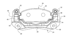
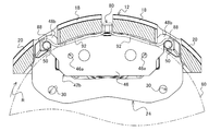
- FIG. 1 is a front view showing a configuration of a disc brake device according to a first embodiment of the present invention.
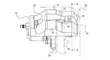
- FIG. 2 is a left side view showing the configuration of the disc brake device according to the first embodiment of the present invention.
- FIG. 3 is a rear view showing the configuration of the disc brake device according to the first embodiment of the present invention.
- FIG. 4 is a top view showing the configuration of the disc brake device according to the first embodiment of the present invention.
- FIG. 5 is a bottom view showing the configuration of the disc brake device according to the first embodiment of the present invention.
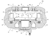
- 6 is a cross-sectional view taken along the line AA in FIG.
- FIG. 7 is a view showing the arrangement of the support with the caliper body removed and the inner brake pads.
- FIG. 8 is a view showing a BB cross section in FIG.
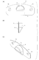
- FIG. 9 is a view showing a cover that can be used in the disc brake device according to this embodiment.
- FIG. 9A is a front view
- FIG. 9B is a left side view
- FIG. 9C is a perspective view.
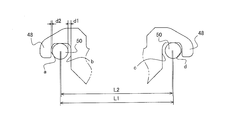
- FIG. 10 is a diagram for explaining the relationship between the ear portion and the sleeve in the outer brake pad, and is a diagram showing a configuration in which the push anchor is shifted to the push / pull anchor.
- FIG. 11 is a view for explaining the relationship between the ear portion and the sleeve in the outer side brake pad, and is a view showing a configuration in which the pull anchor is shifted to the pull anchor.
- FIG. 10 is a diagram for explaining the relationship between the ear portion and the sleeve in the outer brake pad, and is a view showing a configuration in which the pull anchor is shifted to the pull anchor.
- FIG. 12 is a view showing a configuration of a disc brake device according to a second embodiment of the present invention, and is a view showing a CC cross section when FIG. 1 is used.
- FIG. 13 is a view showing a configuration of a disc brake device according to a second embodiment of the present invention, and is a view showing a BB cross section when FIG. 2 is used.
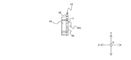
- FIG. 14 is a front view showing a configuration of an outer brake pad used in the disc brake device according to the second embodiment.
- FIG. 15 is a bottom view showing the configuration of the outer brake pad shown in FIG.
- FIG. 16 is a left side view showing the configuration of the outer brake pad shown in FIG. FIG.
- FIG. 17 is a view for explaining an applied form of the outer brake pad applicable to the disc brake device according to the second embodiment of the present invention.
- FIG. 18 is a front view showing a configuration of a disc brake device of a type using a part of the caliper body as an anchoring element.
- 19 is a cross-sectional view of FIG. 18 corresponding to the BB cross section of FIG.
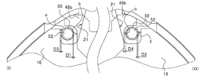
- FIG. 20 is a view showing the arrangement of the caliper body, the sleeve, and the guide pin during non-braking.
- FIG. 21 is a diagram showing the behavior of the caliper body, the sleeve, and the guide pin at the initial stage of braking, and shows a state where the guide pin on the rotor introduction side is in contact with the inner wall of the sleeve.
- FIG. 22 is a diagram showing the behavior of the caliper body, the sleeve, and the guide pin at the initial stage of braking, and shows a state where the guide pins on the rotor introduction side and the extraction side are in contact with the inner wall of the sleeve.
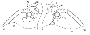
- FIG. 23 is a diagram showing the behavior of the caliper body and the sleeve during braking, and shows a state in which the contact surface e formed in the notch portion on the rotor turn-in side is in contact with the outer peripheral surface of the sleeve.
- FIG. 24 is a diagram illustrating the behavior of the caliper body and the sleeve during braking. The contact surface e formed in the notch portion on the rotor introduction side contacts the outer peripheral surface of the sleeve, and the rotation on the outer brake pad. A state in which the contact surface c provided on the output ear is in contact with the outer peripheral surface of the sleeve is shown.
- FIG. 25 is a view showing the form of an anti-rattle spring used in the disc brake device according to the embodiment shown in FIGS. 18 and 19, wherein FIG. 25 (A) is a front view, FIG. 25 (B) is a plan view, 25 (C) shows the right side.
- FIG. 26 is a view showing an example of a specific configuration of a pad clip applicable to the disc brake device according to the present invention.
- FIG. 26 (A) is a front view
- FIG. 26 (B) is a plan view
- FIG. C) is a right side view
- FIG. 26D is a perspective view.
- the disc brake device 10 is configured based on the caliper body 12, the support 24, the inner side brake pad 34, the outer side brake pad 42, and the rotor 60.
- the caliper body 12 has a cylinder part 14, a claw part 16, a center bridge 18, and a side bridge 20.
- the cylinder part 14 is a drive source of the disc brake device 10 according to the first embodiment, and includes a piston 14a and a cylinder 14b for accommodating and projecting the piston 14a.
- the cylinder portion 14 is provided with a guide pin assembly portion 22 for assembling a guide pin 52 which will be described in detail later.
- the guide pin assembly portion 22 is provided so as to be located outside the outer periphery of the rotor 60. This is because the assembled guide pin 52 is positioned outside the outer periphery of the rotor 60 to avoid interference between the rotor 60 and the guide pin 52.
- the claw portion 16 is a reaction force receiver for the pressing force generated by the piston 14a.
- the claw portion 16 is provided with a notch portion 16a (inner peripheral side notch portion) at a position facing the cylinder forming position in the cylinder portion. This is because the inner peripheral machining of the cylinder 14b in the cylinder portion 14 is performed using the notch portion 16a.
- Each block (two blocks in the example shown in this embodiment) constituting the claw portion 16 is formed with a through hole 16b (see FIG. 12) for inserting a bolt.
- the through hole 16b is a step hole, and it is desirable that the bolt head of the bolt 17 used for fastening does not protrude outward.
- the caliper body 12 is disposed in a limited space between the rotor 60 and the wheel inner wall 95, interference with the wheel can be suppressed by reducing the protruding portion from the caliper body 12, and the flat surface It is because it leads to the improvement of aesthetics by formation.
- the cylinder part 14 and the claw part 16 are connected by a center bridge 18 and a side bridge 20 that straddle the outer side of the outer periphery of the rotor 60.
- a through hole 19 is provided in the center of the center bridge 18.
- the side bridge 20 is provided on the turn-in side (I) and the turn-out side (O) of the rotor 60 with the center bridge 18 as a base point.
- the thickness of the center bridge 18 is reduced while braking.
- the opening between the cylinder part 14 and the claw part 16 and the distortion (tilt) in the rotor rotation direction can be suppressed.
- the caliper body 12 can be disposed in the gap even when the gap between the wheel inner wall 95 of the wheel and the outer periphery of the rotor 60 is narrow.
- the caliper body 12 does not fit between the wheel inner wall 95 and the outer periphery of the rotor 60, it is necessary to take measures such as wheel inch up and rotor size down. In such a case, for example, when the wheel is increased in inches, it is necessary to reduce the flatness of the tire, which may cause a deterioration in ride comfort and an increase in cost due to the mounting of a large-diameter wheel. Further, when the size of the rotor is reduced, it is necessary to secure a wide pressing surface when the piston diameter is increased and the same hydraulic pressure is applied to the rotor. This is because when a high pressing force is applied to the rotor by increasing the hydraulic pressure, the spread between the cylinder portion and the claw portion that occurs during braking increases. In addition, when a large-diameter piston is employed, there are concerns that problems such as an increase in weight and deterioration of the touch feeling of the pedal during a brake operation may occur.
- the overall weight of the disc brake device 10 can be reduced, which can contribute to an improvement in the motion performance of the vehicle. .
- a notch portion 21 (outer peripheral side notch portion) formed so as to be hooked on the claw portion 16 is provided.
- the notch portion 21 is provided at a position corresponding to the guide pin assembly portion 22 in the cylinder portion 14. This is to avoid interference between the caliper body 12 and the guide pin guide portion 32 (the sleeve 50 provided in the guide pin guide portion 32 in the present embodiment) in the support 24 for sliding the guide pin 52.
- the notch portion 21 on the claw portion 16 side is provided in a range of a portion corresponding to the outer side of the outer periphery of the rotor 60.
- part becomes small, and the bending in the said connection site
- the support 24 is fixed to the vehicle body and plays a role of slidably supporting the caliper body 12.
- the support 24 is disposed between the cylinder portion 14 and the claw portion 16 in the caliper body 12, that is, in the frame of the caliper body 12.
- the support 24 includes at least an anchor 26, a bridge 28, a mounting hole 30, and a guide pin guide portion 32.
- the anchor 26 is disposed on each of the return side (I) and the return side (O) of the rotor 60.
- the anchor 26 supports the inner brake pad 34 and also serves as a torque receiver that receives the force that the inner brake pad 34 tries to rotate around the rotor 60 during braking.
- the bridge 28 is a connecting member that connects the anchor 26 arranged on the turn-in side (I) of the rotor 60 and the anchor 26 arranged on the turn-out side (O).
- the mounting holes 30 are provided in the connecting portions between the anchors 26 and the bridges 28, and are holes for fastening the support 24 to the mounting holes (not shown) provided in the vehicle via bolts (not shown). is there.
- the guide pin guide portion 32 is a through hole or a bag hole provided at the tip of the pair of anchors 26 and located outside the outer periphery of the rotor 60 in the assembled state.
- the guide pin guide portion 32 is a through hole, and a sleeve 50 formed in a bag shape is disposed in the through hole, and the guide pin 52 is configured to slide in the sleeve 50. .
- the support 24 is formed of a light metal such as aluminum
- a steel material such as iron is used for the guide pin 52 that is a sliding member.
- electric corrosion electrochemical corrosion
- the sleeve 50 is disposed at a position where the sliding member comes into contact, and the sleeve 50 is made of the same material as the guide pin 52, so that it is possible to prevent electric corrosion occurring between the two and to reduce the weight.
- the support 24 component member is softer than the guide pin 52 component member, the guide pin guide portion 32 may be worn due to sliding, but the hard sleeve 50 is disposed. According to this, this can be prevented.
- the guide pin 52 is a rod-like member that is assembled to the guide pin assembly portion 22 of the cylinder portion 14 in the caliper body 12 described above. Regarding the assembly, the base end of the guide pin 52 is disposed on the cylinder portion 14 and the distal end is disposed on the claw portion 16 side.
- the length of the guide pin 52 may be such a length as to reach the opposing surface of the rotor 60 in the claw portion 16 in the assembled state.
- the guide pin guide portion 32, the sleeve 50, and the guide pin 52 are arranged so as to be positioned in the notch portion 21 formed in the caliper body 12 in the assembled state.
- the guide pin guide portion 32, the sleeve 50, and the guide pin 52 are all inside the arc formed by connecting the center bridge 18 and the two side bridges 20 in the caliper body 12 (that is, the thickness of the back portion). In the range).
- the inner brake pad 34 is a brake pad that is disposed on the inner side of the rotor 60 and is pressed directly by the piston 14 a provided in the cylinder portion 14.
- the inner brake pad 34 includes a lining 36 that is a friction member that comes into contact with the sliding surface of the rotor 60, and a pressure plate 38 that is a steel plate to which the lining 36 is attached.
- the inner brake pad 34 is held by the anchor 26 of the support 24 and is configured to slide in the axial direction of the rotor 60. For this reason, the end portion of the pressure plate 38 (the end portion located on the turn-in side (I) and the turn-out side (O) of the rotor 60 in the assembled state) has a concave shape formed inside the anchor 26.
- Corresponding convex ears 40 are formed. At the time of assembly, a pad clip 54 is disposed between the anchor 26 and the ear portion 40 to suppress rattling of the inner brake pad 34 and to maintain slidability in the axial direction. (See FIG. 7).
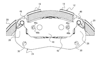
- the outer brake pad 42 is disposed on the outer side of the rotor 60, and is a brake pad that is pressed toward the rotor 60 by the claw 16 by a reaction force caused by the inner brake pad 34 being pressed against the rotor 60.
- the outer brake pad 42 is also composed of a lining 44 and a pressure plate 46, which are friction members.
- the lining 44 is affixed to one surface of the pressure plate 46 that is located on the side of the arrangement surface of the rotor 60 (see, for example, FIGS. 1 and 2) in the assembled state.
- the difference between the inner brake pad 34 and the outer brake pad 42 in the present embodiment is in the form of a pressure plate 46.
- the disc brake device 10 employs a configuration in which the outer brake pad 42 is screwed into the claw portion, that is, fixed by the bolt 17. Therefore, the pressure plate 46 is formed with a female screw hole 46a for bolting (see FIG. 8).
- the formation position of the female screw hole 46 a may be a position corresponding to the through hole 16 b provided in the claw portion 16.
- the outer side brake pad 42 can be fixed to the claw part 16 by the bolt 17 through the through hole 16b.
- the pressure plate 46 of the steel plate is bolted so that the claw part 16 and the pressure plate 46 can be regarded as a single structure.
- the rigidity of the claw portion 16 (caliper body 12) can be improved by using the pressure plate 46 as a strength member.
- the outer brake pad 42 since the outer brake pad 42 is fixed to the claw portion 16, sliding support by the support 24 becomes unnecessary. Therefore, it is not necessary to form the outer frame on the support 24, and the area of the notch 21 in the caliper body 12 provided for preventing interference is suppressed in addition to reducing the manufacturing cost and weight by reducing the size of the support 24. Can also contribute.
- the female screw hole 46a is arranged on the inner side (the inner peripheral side of the rotor 60) with the outer periphery of the rotor 60 as a base point. Further, the female screw hole 46a is arranged within the range of the friction surface in the lining 44 when the outer brake pad 42 is viewed from the front.
- the female screw hole 46a has a straight line l connecting the centers of the two female screw holes 46a in the assembled state, and the center O1 of the cylinder arrangement position of the cylinder 14b provided in the caliper body 12. Arrange to pass through the vicinity.
- the braking torque transmitted from the rotor 60 to the outer brake pad 42 bolted to the claw portion 16 can be transmitted to the caliper body 12 (claw portion 16) without waste. That is, the integrity of the claw portion 16 and the outer brake pad 42 can be enhanced in the tangential direction in which the torque during braking is applied.
- the sleeve 50 and the support 24 are provided. A tangential force can be transmitted to
- the ears 48 formed on the pressure plate 46 are arranged so as to contact the sleeve 50 during braking.
- the ear portion 48 of the outer brake pad 42 contacts the sleeve 50, so that the sleeve 50 serves as an anchor, and the center bridge 18, the side bridge 20, and the claws This is because the load applied to the part 16 can be reduced.
- the guide pin 52 accommodated in the sleeve 50 has a length from the cylinder portion 14 to the opposing surface of the rotor 60 in the claw portion 16.
- the ear portion 48 of the pressure plate 46 in the outer brake pad 42 is a hanger type that covers the sleeve 50 from above and faces the radially inner periphery of the rotor 60. And a torque receiving portion in which a concave notch having an open portion is formed.
- the tip end side of the ear portion 48 abuts on the sleeve 50, and a so-called pulling anchor state is established.
- the proximal end side of the ear portion 48 comes into contact with the sleeve 50 and is in a so-called pushing anchor state. Further, according to such a configuration, the caliper body 12 can be assembled to the support 24 on which the sleeve 50 is disposed after the outer brake pad 42 is assembled to the claw portion 16.
- an axis parallel to a straight line passing through the rotation center O0 of the rotor 60 and the center O1 (cylinder center) of the cylinder arrangement position of the cylinder 14b in plan view is defined as the Y axis.
- a straight line orthogonal to the Y axis is defined as the X axis
- a straight line that intersects the Y axis and the X axis and is parallel to the rotation axis of the rotor 60 is defined as the Z axis.
- the four surfaces of the contact surface a, the contact surface b, the contact surface c, and the contact surface d which are contact surfaces of the ear portion 48 and the sleeve 50, are respectively It is formed to be parallel.
- the ear portion 48 is a torque receiving portion in which a concave notch is formed.
- d is a torque receiving surface.
- the contact surfaces a to d are formed in parallel to the Y axis, more specifically, the surface formed by the Y axis and the Z axis (YZ surface).
- the outer peripheral surface of the sleeve 50 is disposed in parallel with the Z-axis, so that the transmission loss of the braking torque at the time of contact is reduced by adopting such a configuration.
- the shape of the ear portion 48 is such, by adjusting the gap between the ear portion 48 and the sleeve 50, only the push anchor, only the pull anchor, or the push anchor ( Alternatively, it is possible to use only a pull anchor and a pull anchor and a pull anchor (or a pull anchor and a push anchor) during the main braking.
- FIGS. 10 and 11 An example of the relationship between the push-pull anchor and the sleeve is shown in FIGS. 10 and 11, respectively. In the following description, as shown in FIG. 8, the rotation direction of the rotor 60 is assumed to be clockwise (clockwise).
- FIG. 10 shows an example in which the center-to-center distance L2 of the hook part (concave notch) of the ear part 48 is longer than the center-to-center distance L1 of the sleeve 50 (guide pin 52).
- the gap d2 generated between the sleeve 50 and the hook portion of the ear 48 is closer to the gap d2 generated on the end side of the pressure plate than the gap d1 generated on the center side of the pressure plate 46. Becomes larger.
- the sleeve 50 including the caliper body 12 or the guide pin 52 is less bent at the initial stage of braking, the sleeve 50 and the ear portion 48 disposed on the delivery side (O) of the rotor 60 are The gap d1 becomes zero, and the contact surface c comes into contact with the sleeve 50 to be in a pushing anchor state. Thereafter, when the tangential force increases, the gap d2 between the sleeve 50 and the ear portion 48 disposed on the turn-in side (I) of the rotor 60 becomes zero, and the contact surface a and the sleeve 50 come into contact with each other to pull the anchor. It becomes a state. That is, in the case of L1 ⁇ L2, d1 ⁇ d2 is obtained, and the structure reaches from the push anchor to the push / pull anchor state.
- the example shown in FIG. 11 shows an example in which the center distance L2 of the hook portion of the ear 48 is shorter than the center distance L1 of the sleeve 50 (guide pin 52).
- the gap d2 generated between the sleeve 50 and the hook portion of the ear 48 is closer to the gap d2 generated on the end side of the pressure plate than the gap d1 generated on the center side of the pressure plate 46. Becomes smaller.
- the rotor 60 is a rotating plate disposed between the inner brake pad 34 and the outer brake pad 42, and has a sliding surface at a position facing the linings 36 and 44 in each brake pad.
- the rotor 60 is fixed so as to rotate with a wheel (not shown).
- the disc brake device 10 is provided with a cover 70 that covers the notch portion 16a formed in the claw portion 16.
- the cover 70 smoothes the unevenness generated on the outer side surface (front surface) of the caliper body 12 and changes the appearance impression of the caliper body 12.
- the cover 70 includes a base plate 72 and a cover plate 74.
- the base plate 72 is a plate for fixing the cover 70 to the caliper body 12.
- the base plate 72 in the case of this embodiment is disposed between the pressure plate 46 of the outer brake pad 42 and the claw portion 16, and is fastened together by bolts 17 that fix the pressure plate 46 to the claw portion 16.
- the base plate 71 is formed with a fixing hole 72a through which the bolt 17 is inserted.
- the cover plate 74 is a main part of the cover 70, and its shape varies widely. For example, in the case of this embodiment, it is formed so as to be convex with respect to the base plate 72 so as to smooth the step between the pressure plate 46 caused by the notch 16a and the outer side surface of the claw 16. Yes.
- the cover plate 74 formed in a convex shape is inclined along the thin portion of the claw portion 16 so that the convex thickness is reduced toward the direction of the inner diameter side of the rotor 60. It has been. In this way, the notch 16a covers the step formed on the outer side surface of the caliper body 12, and the appearance impression is changed, thereby improving the design of the disc brake device 10 and giving a so-called high-class feeling and individuality. It becomes possible.
- the notch portion 16a is covered by the bolt-fixable cover 70, it is possible to easily give a change or accent to the appearance of the caliper body 12 simply by exchanging it. Moreover, since it is not the structure which covers the caliper body 12 whole, heat dissipation can be kept favorable and brake performance can be maintained favorable. Further, it is lighter than that covering the entire caliper body 12. For this reason, when it sees as the whole vehicle, it leads also to an improvement in a fuel consumption.
- FIG. 12 is a cross-sectional view showing a characteristic configuration of the disc brake device according to the second embodiment. When FIG. 1 is used, it corresponds to a CC cross section.
- FIG. 13 is a cross-sectional view taken along the line BB when FIG. 2 is used.
- the difference between the disc brake device 10a according to the second embodiment and the disc brake device 10 according to the first embodiment lies in the configuration of the outer brake pad 42.
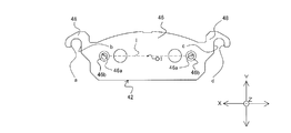
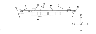
- the pressure plate 46 constituting the outer brake pad 42 is provided with a boss 46b that fits into the through hole 16b formed in the claw portion 16.
- the pressure plate 46 of the outer brake pad 42 according to the second embodiment includes a plate body, a boss 46b, and an ear 48.
- the plate body is an area for attaching the lining 44 described above, and is formed to be slightly larger than the outer shape of the lining 44.
- the boss 46b protrudes from the other surface of the pressure plate 46 opposite to the surface to which the lining 44 is attached, that is, the surface facing the claw portion 16 of the caliper body 12 in the assembled state (for example, (See FIGS. 1 and 2). For this reason, when the pressure plate 46 is viewed from the front, the boss 46 b is provided within the range of the friction surface of the lining 44.
- the bosses 46b are provided in at least a pair (two), and are provided so as not to be positioned on the inner peripheral side of the cylinder 14b in the cylinder portion 14 when viewed from the front in the assembled state (for example, FIGS. 8 and 10). reference).
- the paired bosses 46b are provided at positions corresponding to the claw portions 16 located on the turn-in side (I) of the rotor 60 and the claw portions 16 located on the turn-out side (O) of the rotor 60, respectively. .
- the boss 46b can be fitted into the through hole 16b formed in the claw portion 16, and the claw portion 16 and the pressure plate 46 can be integrated.
- the straight line l connecting the centers of the paired bosses 46b overlaps the cylinder portion 14 with the position overlapping the rotation center O0 of the rotor 60 when the disc brake device 10 with the outer brake pad 42 assembled is viewed from the front.
- An axis parallel to a straight line passing through a position overlapping the center O1 of the cylinder arrangement position of the cylinder 14b formed on the cylinder 14b and parallel to the plate surface of the pressure plate 46 is defined as a Y axis
- the tangent of the rotor 60 to the Y axis When an axis parallel to a straight line orthogonal to the direction (a straight line along the load direction of the tangential force received during braking) is defined as the X axis, the center O1 of the cylinder arrangement position of the cylinder 14b is parallel to the X axis, or It passes through the vicinity (see FIG.
- the boss 46b By providing the boss 46b in such an arrangement, the direction of the tangential force applied to the center of pressing by the piston 14a (actually, the pressing portion by the claw portion 16 that receives a reaction force against pressing) and the straight line l are obtained. Overlap. Therefore, the integrity of the claw portion 16 and the outer brake pad 42 can be improved in the direction in which the tangential force is applied, and the tangential force can be transmitted to the claw portion 16 of the caliper body 12 without loss. Can do. That is, the outer side brake pad 42 can act as a strength member of the caliper body 12.
- the vicinity of the center O1 of the cylinder arrangement position here is an allowable range of the deviation width of the straight line 1 along the Y-axis direction, and is, for example, about the diameter of the boss 46b or the diameter of a female screw hole 46a described later. It can be a range.
- Each of the bosses 46b is formed with a female screw hole 46a along the protruding direction of the boss 46b (in the case of defining the axis, an axis parallel to the axial direction of the rotor 60 (Z axis)). Since the female screw hole 46a is provided in the boss 46b, the boss 46b fitted into the through hole 16b formed in the claw portion 16 is screwed by the bolt 17 and can be stably fastened to the claw portion 16 ( (See FIG. 12). As a result, the pressure plate 46 in the outer brake pad 42 can be regarded as a single body structure with the claw portion 16, and the outer brake pad 42 (pressure plate 46) is used as a strength member and the two notches 16 a are used as two members. The rigidity of the claw part 16 (caliper body 12) divided into blocks can be improved.
- the ear 48 abuts against a guide pin 52 (see a sleeve 50 described in detail later in the second embodiment: see FIG. 6 and the like) during braking, and receives a tangential force with the guide pin 52 and the sleeve 50 as anchors. Take on. For this reason, when the caliper body 12 bends during braking, the ear portion 48 of the outer brake pad 42 abuts on the sleeve 50, and the caliper body 12 can be prevented from bending. For this reason, the tangential force at the time of braking is transmitted to the caliper body 12 and transmitted from the ear portion 48 to the sleeve 50 as a part of the caliper body 12.
- the tangential force is transmitted from the caliper body 12 directly to the base side of the guide pin 52 connected to the support 24 in addition to the transmission from the ear 48 to the sleeve 50. For this reason, the partial wear of the lining 44 due to the inclination of the posture of the caliper body 12 and the distortion of the sleeve 50 (guide pin 52) can be suppressed.
- the guide pin 52 accommodated in the sleeve 50 has a length from the cylinder portion 14 to the opposing surface of the rotor 60 in the claw portion 16. For this reason, when the pressure plate 46 of the outer side brake pad 42 fixed to the opposing surface of the rotor 60 in the claw portion 16 contacts the sleeve 50, the guide pin 52 is disposed therein. Therefore, there is no possibility that the sleeve 50 is damaged such as a dent due to the contact of the ear 48.
- the guide pin 52 (sleeve 50) is disposed on the outer peripheral side of the rotor 60. It is assumed that the disc brake device 10 (10a) is assembled. For this reason, the ear
- a disc brake device having a guide pin that protrudes toward the rotor side on the inner peripheral side of the rotor outer diameter after the support straddles the rotor is also provided.
- the weight of the support is increased, and it is necessary to provide guide pins on the inner side and the outer side of the rotor. It is desirable to employ the disc brake device 10a as in the embodiment.
- the reliability in terms of safety can be further improved compared to the disc brake device 10 according to the first embodiment.
- the outer side brake pad 42a corresponding to the present embodiment is different in the form of the ear 48 from the outer side brake pad 42 described in the above embodiments.
- the ear portion 48 of the outer side brake pad 42 described in each of the above embodiments is a hanger type, whereas the ear portion 48a of the outer side brake pad 42a in this embodiment is a contact surface 49 cut off linearly.
- the contact surface 49 formed on the ear portion 48a is configured in parallel to the Y axis, more specifically, the surface formed by the Y axis and the Z axis (YZ plane), as in the above embodiments. Is done.
- the anchor effect by the sleeve 50 can be obtained at the time of braking since the contact surface 49 with the sleeve 50 is provided.
- the ear portion 48a in this embodiment is a cut-off contact surface 49, it is not possible to obtain an anchor effect by a so-called pull anchor.
- the anchor effect is only due to the pushing anchor against the sleeve 50 located on the delivery side (O) of the rotor 60.
- a thing like this form is employ
- adopted as a form of the pressure plate 46 a plate-formability will improve compared with what was demonstrated in said each embodiment. For this reason, the material cost and weight can be reduced, and the processing cost accompanying simplification of the outer shape can be reduced.
- the claw portion 16 integrated with the outer brake pad 42b by fixing via the bolt 17 is used as a torque receiving element. It is the same as the form. Therefore, portions having the same configuration are denoted by the same reference numerals in the drawings, and detailed description thereof is omitted.
- a specific difference from the disc brake devices 10 and 10a according to the above embodiments is the configuration of the notch 21.
- the notch portion 21 is provided so as to avoid interference between the caliper body 12 and the sleeve 50.
- the contact surfaces e and f are formed on the side wall of the claw portion 16 located on the side bridge 20 side in the notch portion 21 provided in the caliper body 12. (See FIG. 20).
- the contact surface e provided in the notch 21 contacts the sleeve 50 on the turn-in side (I) of the rotor 60, thereby forming a pulling anchor and On the outlet side (O), the contact surface c provided on the ear portion 48b of the pressure plate 46 comes into contact with the sleeve 50, thereby forming a push anchor (see FIG. 20).
- the caliper body 12 fastened to the pressure plate 46 since a part of the caliper body 12 fastened to the pressure plate 46 is used as an anchor element and an anchor effect is exerted, there is no need to use a hanger type with a wide plate width of the ear portion. For this reason, even when the gap with the wheel inner wall 95 is narrow, it is possible to realize the pulling anchor on the turn-in side (I) of the rotor 60. Furthermore, in order to form the contact surfaces e and f in the notch portion 21, by forming the portions in a convex shape, the opening area of the notch portion 21 is substantially reduced. For this reason, the rigidity of the caliper body 12 can be increased.
- the contact surfaces e and f of the caliper body 12 are processed by inserting the cutting tool from the radial direction of the rotor 60 and sliding the inserted cutting tool in the axial direction. can do.
- a notch 21 is provided between the center bridge 18 and the side bridge 20 in the caliper body 12. For this reason, a cutting tool can be inserted using the notch 21.
- the gap between each contact surface and the sleeve 50 is determined as shown in FIG. That is, when the rotation direction of the rotor 60 is clockwise (rotation from right to left in the figure), the gap between the contact surface e provided on the notch 21 on the turn-in side (I) and the sleeve 50. D3 is set to be narrower than the gap D4 between the contact surface c provided on the ear portion 48b on the delivery side (O) and the sleeve 50. Further, in the disc brake device 10b according to the present embodiment, the gaps D1 and D2 between the sleeve 50 and the guide pin 52 are determined so as to satisfy D2> D1 by design.
- an anti-rattle spring is assembled to the disc brake device 10b according to the present embodiment.
- the anti-rattle spring is an element for preventing the caliper body 12 from falling and stabilizing the posture (radial positioning element).
- the anti-rattle spring 80 includes a caliper side engaging portion 82 and a sleeve side engaging portion 88, which are connected by a spring portion 92.
- 25A is a view showing a front form of the anti-rattle spring 80
- FIG. 25B is a plan view
- FIG. 25C is a right side view.
- a clip portion 84 and a load point 86 are provided in the caliper side engaging portion 82 in the anti-rattle spring 80 having the form shown in FIG.
- the clip portion 84 sandwiches a part of the caliper body 12 (in the example shown in FIG. 18, sandwiches the thinned portion of the back portion forming the through hole 19 formed in the center bridge 18. ), An element for stably holding the anti-rattle spring 80 on the caliper body 12.
- the load point 86 in the caliper side engaging portion 82 contacts the inner peripheral side of the caliper body 12 and applies a load in a direction in which the caliper body 12 is lifted (a direction toward the outer peripheral side in the radial direction of the rotor 60).
- the sleeve side engaging portion 88 has a load point 90 that comes into contact with the sleeve 50.
- the load point 90 of the sleeve side engaging portion 88 applies a load in a direction in which the sleeve 50 is pushed down (a direction toward the radially inner side of the rotor).
- the caliper body 12 When the load as described above is applied by the load points 86 and 90, the caliper body 12 is pushed up with the sleeve 50 as a base point on the claw portion 16 side, and the posture can be stabilized. it can. Thereby, the unnecessary rocking
- FIGS. 26A is a diagram showing a front view of the pad clip
- FIG. 26B is a plan view
- FIG. 26C is a right side view
- FIG. 26D is a perspective view. It is a figure which shows a form, respectively.
- the pad clip 100 is arranged such that the outer brake pad 42b (including the caliper body 12 fastened to the outer brake pad 42b) is positioned at the center between the sleeves 50 that are torque receiving portions in the circumferential direction of the rotor 60. While controlling the attitude (circumferential positioning element), it is an element for preventing the wear and wear of the covering portion.
- the pad clip 100 includes a main body plate 102 and a cover plate 106, and both are connected by a spring member 104.
- the main body plate 102 is disposed between the claw portion 16 and the pressure plate 46.
- the outer side brake pad 42 b is fastened to the claw portion 16 by the bolt 17, whereby the pad clip 100 is positioned.
- the cover plate 106 has a hanger shape and is arranged so as to cover the outer peripheral surface of the sleeve 50 from the outer peripheral side of the rotor 60. With such a configuration, contact between the ear portion 48a and the outer peripheral portion of the sleeve 50 can be avoided. As a result, it is possible to suppress wear and abrasion due to electric corrosion between different metals and impact during sliding and braking.
- the spring member 104 positions the outer brake pad 42b arranged between the two sleeves 50 in the circumferential direction. As a result, the circumferential position of the caliper body 12 integrated with the outer brake pad 42b is also stabilized.
- a claw having a cylinder portion 14 disposed on the inner side of the rotor 60 and an inner notch portion (notch portion) 16a disposed on the outer side of the rotor 60 and facing the cylinder placement position.
- the portion 16 is connected to the center bridge 18 by the side bridge 20 disposed on the turn-in side (I) and the turn-out side (O) of the rotor 60 with the center bridge 18 as a base point, and an outer peripheral side cutout portion.
- (Notch part) 21 is exposed to the outside of the caliper body from the caliper body 12 provided between the center bridge 18 and the side bridge 20 and the outer peripheral side notch part (notch part) 21,
- a guide pin guide portion 32 disposed within the thickness range of the back meat constituting the center bridge 18 and the side bridge 20 is provided between the cylinder portion 14 and the claw portion 16.
- a support 24 provided, a guide pin 52 that slides on the guide pin guide portion 32 in the support 24, an inner brake pad 34 and an outer brake pad disposed on the inner side and the outer side of the rotor 60, respectively.
- the guide pin guide portion 32 includes a sleeve 50 made of a member having the same strength as the guide pin 52, and The guide pin 52 is a disc brake device 10 that slides on the inner peripheral side of the sleeve 50.
- the disc brake device 10 having the configuration of [2] above, wherein the guide pin 52 has a length reaching the surface of the claw portion 16 facing the rotor 60 in the sleeve 50.
- the outer brake pad 42 includes a friction member (lining) 44 and a pressure plate 46 screwed into the claw portion 16, and the pressure plate 46 has an ear portion that contacts the sleeve 50 during braking.
- a disc brake device 10 provided with 48.
- the disc brake device 10a having the configuration of the above [3], in which the ear portion 48a has a contact surface 49 with respect to the sleeve 50 located on the delivery side (O) of the rotor 60. Device 10a.
- the disc brake device 10b having the configuration of the above [4], wherein the outer circumferential notch (notch) 21 is located on the turn-in side (I) of the rotor 60.
- a disc brake device 10b having contact surfaces e and f against the sleeve 50 on the side wall.
- the disc brake device 10 having the configuration of [3] above, wherein the ear portion 48 is located on both the turn-in side (I) and the turn-out side (O) of the rotor 60.
- Disc brake device 10 having contact surfaces a, b, c, d with respect to [7]
- the disc brake device 10 having the configuration of any one of [4] to [6], wherein an axis parallel to a straight line passing through the rotation center O0 of the rotor 60 and the center O1 of the cylinder arrangement position is provided.
- the disc brake device 10 in which two or four contact surfaces a, b, c, and d with respect to the sleeve 50 are arranged in parallel to the Y axis when defined as the Y axis.
- the claw portion 16 of the pressure plate 46 is disposed on the surface facing the claw portion 16 for screwing.
- the disc brake device 10a is provided with a boss 46b that can be fitted into a through hole 16b provided in the portion 16.
- a disc brake device 10b having the configuration of any one of [2] to [8], wherein an anti-rattle spring 80 is provided between the caliper body 12 and the sleeve 50.
- Device 10b [10] A disc brake device 10b having any one of the above configurations [3] to [9], wherein a contact portion of the sleeve 50 with the outer brake pad 42b and a contact portion with the caliper body 12 are provided.
- a cover plate 106 covering at least one of the contact portions, and a main body plate 102 interposed between the pressure plate 46 and the claw portion 16 are provided, and the cover plate 106 and the main body plate 102 are connected to a spring member 104.
- the disc brake device 10 having the configuration according to any one of [1] to [10] above, and a cover that fills a step between the inner peripheral notch (notch) 16a and the claw 16 Disc brake device 10 provided with 70.
- the disc brake device 10 having the above-described configuration [11], in which the cover 70 is interposed between the pressure plate 46 of the outer brake pad 42 and the claw portion 16.
- the base plate 72 is provided with a fixing hole 72a that can be fastened to the claw portion 16 together with the outer brake pad 42.
- a disc brake device brake pad (outer side brake pad) 42 having a friction member (lining) 44 and a pressure plate 46 to which the friction member (lining) 44 is affixed.
- the at least two bosses 46b projecting from the surface opposite to the surface on which the friction member (lining) 44 is affixed are disposed on each of the inlet side (I) and outlet side (O) of the rotor 60.
- a torque receiving portion (ear portion) 48 is provided, and a female screw hole 46a used for fixing the pressure plate 46 to the caliper body 12 is formed on the protruding surface of the boss 46b.
- a disc brake device brake pad (outer brake pad) 42 provided along the protruding direction. [15] A disc brake device brake pad (outer side brake pad) 42 having the configuration of [14] above, wherein the boss 46 b is disposed at a position on the inner peripheral side with respect to the outer diameter of the rotor 60.
- the torque receiving portion (ear portion) 48 is a disc brake device brake pad (outer side brake pad) 42 disposed at a position on the outer peripheral side with respect to the outer diameter of the rotor 60.
- a disc brake device brake pad (outer side brake pad) 42 having the configuration of [15] above, wherein the boss 46b has a straight line l connecting the centers of two bosses 46b forming a pair. It is arranged parallel to a straight line along the load direction of the tangential force that is sometimes received, and at a position that overlaps the cylinder center (center of the cylinder arrangement position) O1 in the caliper body 12 or a position that passes the vicinity thereof in the front view in the assembled state.
- a disc brake device brake pad (outer brake pad) 42 having the configuration of [16] above, wherein the torque receiving portion (ear portion) 48 is opened in the inner circumferential direction of the rotor 60.
- a disc brake device brake pad (outer side brake pad) 42 having the configuration of [17] above, wherein opposing surfaces (contact surfaces) a, b, c, d of the concave notches are Discs provided parallel to the Y axis, which are parallel to each other and parallel to a straight line passing through a position overlapping the cylinder center (center of the cylinder arrangement position) O1 and a position overlapping the rotation center O0 of the rotor 60.
- Brake pad for brake device (outer side brake pad) 42 having the configuration of [17] above, wherein opposing surfaces (contact surfaces) a, b, c, d of the concave notches are Discs provided parallel to the Y axis, which are parallel to each other and parallel to a straight line passing through a position overlapping the cylinder center (center of the cylinder arrangement position) O1 and a position overlapping the rotation center O0 of the rotor 60.
- the disc brake device and the disc brake device brake pad of the present invention are not limited to the above-described embodiment, and can be appropriately modified and improved.
- the material, shape, dimensions, number, arrangement location, and the like of each component in the above-described embodiment are arbitrary and are not limited as long as the present invention can be achieved.
- the present application includes a Japanese patent application filed on October 26, 2012 (Japanese Patent Application No. 2012-236574), a Japanese patent application filed on October 26, 2012 (Japanese Patent Application No. 2012-236777), and September 19, 2013. This is based on the Japanese patent application (Japanese Patent Application No. 2013-194028), the contents of which are incorporated herein by reference.
- the disc brake device it is possible to provide a disc brake device that can be mounted in a narrow wheel space while maintaining an appropriate rigidity while achieving weight reduction.
- the disc brake device can be reduced in weight, and the caliper body posture can be ensured during braking and the occurrence of uneven wear of the friction member can be suppressed. It becomes possible.
Landscapes
- Engineering & Computer Science (AREA)
- General Engineering & Computer Science (AREA)
- Mechanical Engineering (AREA)
- Braking Arrangements (AREA)
Abstract
L'invention porte sur un dispositif de frein à disque, qui comprend : un corps d'étrier (12) dans lequel une section de cylindre (14) et une section de dent (16) ayant une section de découpe (16a) sont reliées par un pont central (18) et un pont latéral (20), et dans lequel une section de découpe (21) est placée entre le pont central (18) et le pont latéral (20) ; un support (24) comprenant une section de guidage de tige de guidage (32) qui est placée entre la section de cylindre (14) et la section de dent (16) : une tige de guidage (52) qui coulisse dans la section de guidage de tige de guidage (32) ; et une garniture de frein côté extérieur (42) qui est vissée à une surface de la section de dent (16), qui est opposée à un rotor (60) à chacun du côté de bord d'attaque et du côté de bord de fuite du rotor dans la section de découpe (16a).
Priority Applications (3)
| Application Number | Priority Date | Filing Date | Title |
|---|---|---|---|
| US14/430,725 US9920799B2 (en) | 2012-10-26 | 2013-10-25 | Disk brake device and brake pad for disk brake device |
| EP13849576.7A EP2913551B1 (fr) | 2012-10-26 | 2013-10-25 | Dispositif de frein à disque |
| CN201380056264.2A CN104755786B (zh) | 2012-10-26 | 2013-10-25 | 盘式制动器装置和用于盘式制动器装置的制动垫板 |
Applications Claiming Priority (6)
| Application Number | Priority Date | Filing Date | Title |
|---|---|---|---|
| JP2012236574 | 2012-10-26 | ||
| JP2012-236574 | 2012-10-26 | ||
| JP2012-236577 | 2012-10-26 | ||
| JP2012236577A JP2014084997A (ja) | 2012-10-26 | 2012-10-26 | ディスクブレーキ装置用ブレーキパッド |
| JP2013-194028 | 2013-09-19 | ||
| JP2013194028A JP6202434B2 (ja) | 2012-10-26 | 2013-09-19 | ディスクブレーキ装置 |
Publications (1)
| Publication Number | Publication Date |
|---|---|
| WO2014065400A1 true WO2014065400A1 (fr) | 2014-05-01 |
Family
ID=53593838
Family Applications (1)
| Application Number | Title | Priority Date | Filing Date |
|---|---|---|---|
| PCT/JP2013/078953 WO2014065400A1 (fr) | 2012-10-26 | 2013-10-25 | Dispositif de frein à disque et garniture de frein pour dispositif de frein à disque |
Country Status (4)
| Country | Link |
|---|---|
| US (1) | US9920799B2 (fr) |
| EP (1) | EP2913551B1 (fr) |
| CN (1) | CN104755786B (fr) |
| WO (1) | WO2014065400A1 (fr) |
Cited By (2)
| Publication number | Priority date | Publication date | Assignee | Title |
|---|---|---|---|---|
| DE102015114351A1 (de) * | 2015-08-28 | 2017-03-02 | Knorr-Bremse Systeme für Nutzfahrzeuge GmbH | Scheibenbremse eines Nutzfahrzeugs |
| US11002325B2 (en) * | 2017-12-15 | 2021-05-11 | Meritor Heavy Vehicle Braking Systems (Uk) Limited | Brake caliper |
Families Citing this family (10)
| Publication number | Priority date | Publication date | Assignee | Title |
|---|---|---|---|---|
| JP6680554B2 (ja) * | 2015-07-09 | 2020-04-15 | 曙ブレーキ工業株式会社 | ディスクブレーキ装置 |
| USD785520S1 (en) * | 2015-07-20 | 2017-05-02 | Freni Brembo S.P.A. | Disc brake calliper |
| JP2017082968A (ja) * | 2015-10-30 | 2017-05-18 | 曙ブレーキ工業株式会社 | ディスクブレーキ装置 |
| KR102274117B1 (ko) * | 2017-02-15 | 2021-07-06 | 현대자동차주식회사 | 브레이크 캘리퍼 어셈블리 |
| KR102440006B1 (ko) * | 2017-08-23 | 2022-09-05 | 현대모비스 주식회사 | 차량용 브레이크의 캘리퍼 장치 |
| EP3450790A1 (fr) * | 2017-08-31 | 2019-03-06 | Meritor Heavy Vehicle Braking Systems (UK) Limited | Frein à disque |
| JP7109954B2 (ja) * | 2018-03-27 | 2022-08-01 | 曙ブレーキ工業株式会社 | ディスクブレーキ用パッド |
| JP7084174B2 (ja) | 2018-03-27 | 2022-06-14 | 曙ブレーキ工業株式会社 | フローティング型ディスクブレーキ |
| EP3791085B1 (fr) * | 2018-05-09 | 2022-03-09 | Continental Teves AG & Co. OHG | Plâte de support de semelle de frein à disque confectionée en dépendance de la direction de rotation |
| JP7043353B2 (ja) * | 2018-06-14 | 2022-03-29 | 曙ブレーキ工業株式会社 | 対向ピストン型ディスクブレーキ装置 |
Citations (14)
| Publication number | Priority date | Publication date | Assignee | Title |
|---|---|---|---|---|
| JPS54137572A (en) | 1978-04-15 | 1979-10-25 | Tokico Ltd | Disc brake |
| JPS5680530A (en) | 1979-12-03 | 1981-07-01 | Kelsey Hayes Co | Sliding calipers disc brake |
| JPS57149629A (en) * | 1981-03-09 | 1982-09-16 | Sumitomo Electric Ind Ltd | Disc brake |
| JPH0536137U (ja) * | 1991-10-21 | 1993-05-18 | 日信工業株式会社 | 車両用デイスクブレーキ |
| JPH0849736A (ja) | 1994-08-08 | 1996-02-20 | Toyota Motor Corp | ディスクブレーキの分割型キャリパ |
| JP2001503500A (ja) | 1996-07-01 | 2001-03-13 | コンティネンタル・テーベス・アクチエンゲゼルシヤフト・ウント・コンパニー・オッフェネ・ハンデルスゲゼルシヤフト | 浮動キャリパ型ディスクブレーキ用のばね装置 |
| JP2002089596A (ja) | 2000-09-18 | 2002-03-27 | Nissin Kogyo Co Ltd | 車両用ディスクブレーキのピンスライド型キャリパボディ |
| JP2004204936A (ja) * | 2002-12-25 | 2004-07-22 | Orion Denki Kk | 薄板部材のネジ止め構造 |
| JP2005023944A (ja) * | 2003-06-30 | 2005-01-27 | Mitsubishi Electric Corp | 薄板のねじ締結構造 |
| JP2005525519A (ja) * | 2002-05-14 | 2005-08-25 | コンチネンタル・テベス・アーゲー・ウント・コンパニー・オーハーゲー | フローティングキャリパとブレーキ支持部材に直接支えられた複数の外側ブレーキパッドとを有するディスクブレーキ |
| JP2005308224A (ja) * | 2004-04-22 | 2005-11-04 | Akebono Corp North America | ワイドキャリパ組立体 |
| JP2006520450A (ja) | 2003-03-20 | 2006-09-07 | ルーカス・オートモーティブ・ゲーエムベーハー | ディスクブレーキ |
| JP2009534599A (ja) * | 2006-04-20 | 2009-09-24 | コンチネンタル・テベス・アーゲー・ウント・コンパニー・オーハーゲー | ディスクブレーキ |
| JP2012117654A (ja) * | 2010-12-03 | 2012-06-21 | Akebono Brake Ind Co Ltd | ディスクブレーキ装置 |
Family Cites Families (21)
| Publication number | Priority date | Publication date | Assignee | Title |
|---|---|---|---|---|
| US3388774A (en) * | 1966-09-01 | 1968-06-18 | Bendix Corp | Adjustable bearing means for a disc brake |
| US3532191A (en) * | 1968-10-31 | 1970-10-06 | Bendix Corp | Adjustable bearing means for a disc brake |
| US4072216A (en) | 1975-08-14 | 1978-02-07 | Tokico Ltd. | Disc brake guiding and support structure |
| US4385680A (en) * | 1978-08-28 | 1983-05-31 | The Bendix Corporation | Pin slider disc brake |
| FR2539833B1 (fr) | 1983-01-20 | 1985-07-05 | Dba | Frein a disque a etrier coulissant |
| US4540068A (en) | 1983-02-22 | 1985-09-10 | Allied Corporation | Disc brake |
| SE464592B (sv) * | 1989-02-10 | 1991-05-13 | Volvo Ab | Anordning vid skivbromsar |
| JP3211662B2 (ja) * | 1995-06-05 | 2001-09-25 | 住友電気工業株式会社 | ディスクブレーキ |
| US5860496A (en) * | 1996-12-18 | 1999-01-19 | Itt Automotive Inc. | Pin guided push-pull caliper |
| US5957245A (en) * | 1997-08-05 | 1999-09-28 | Itt Manufacturing Enterprises Inc. | Disc brake, disc brake caliper and disc brake shoe |
| US6256858B1 (en) * | 1999-04-08 | 2001-07-10 | Qualitee Internation Limited Partnership | Shim structure for sound dampening brake squeal noise |
| JP2001193769A (ja) * | 1999-12-14 | 2001-07-17 | Continental Teves Ag & Co Ohg | 自動車用部分パッド型ディスクブレーキ |
| DE10027783A1 (de) * | 2000-06-07 | 2002-01-03 | Lucas Automotive Gmbh | Befestigung des Firmenmarkenzeichens an dem Bremssattel einer Scheibenbremse |
| DE10131324A1 (de) | 2000-12-21 | 2002-07-11 | Continental Teves Ag & Co Ohg | Schwimmsattel-Scheibenbremse |
| US20040188188A1 (en) | 2003-03-24 | 2004-09-30 | Manuel Barbosa | One piece sliding brake caliper |
| US20070045064A1 (en) | 2005-08-25 | 2007-03-01 | Akebono Corporation (North America) | Mass reduction for twin piston calipers |
| US8191690B2 (en) * | 2008-04-15 | 2012-06-05 | Material Sciences Corporation | Shim structure for brake squeal attenuation |
| JP4741693B2 (ja) * | 2009-06-25 | 2011-08-03 | 本田技研工業株式会社 | 化粧プレートの取付構造 |
| KR101394126B1 (ko) | 2009-12-09 | 2014-05-14 | 주식회사 만도 | 디스크 브레이크 |
| FR2965027A1 (fr) | 2010-09-16 | 2012-03-23 | Peugeot Citroen Automobiles Sa | Frein a disque a etrier flottant pour vehicule automobile |
| JP2013204742A (ja) * | 2012-03-29 | 2013-10-07 | Honda Motor Co Ltd | ディスクブレーキ装置 |
-
2013
- 2013-10-25 EP EP13849576.7A patent/EP2913551B1/fr not_active Revoked
- 2013-10-25 US US14/430,725 patent/US9920799B2/en not_active Expired - Fee Related
- 2013-10-25 WO PCT/JP2013/078953 patent/WO2014065400A1/fr active Application Filing
- 2013-10-25 CN CN201380056264.2A patent/CN104755786B/zh not_active Expired - Fee Related
Patent Citations (15)
| Publication number | Priority date | Publication date | Assignee | Title |
|---|---|---|---|---|
| JPS54137572A (en) | 1978-04-15 | 1979-10-25 | Tokico Ltd | Disc brake |
| JPS5680530A (en) | 1979-12-03 | 1981-07-01 | Kelsey Hayes Co | Sliding calipers disc brake |
| JPS57149629A (en) * | 1981-03-09 | 1982-09-16 | Sumitomo Electric Ind Ltd | Disc brake |
| JPH0536137U (ja) * | 1991-10-21 | 1993-05-18 | 日信工業株式会社 | 車両用デイスクブレーキ |
| JPH0849736A (ja) | 1994-08-08 | 1996-02-20 | Toyota Motor Corp | ディスクブレーキの分割型キャリパ |
| JP2001503500A (ja) | 1996-07-01 | 2001-03-13 | コンティネンタル・テーベス・アクチエンゲゼルシヤフト・ウント・コンパニー・オッフェネ・ハンデルスゲゼルシヤフト | 浮動キャリパ型ディスクブレーキ用のばね装置 |
| JP2002089596A (ja) | 2000-09-18 | 2002-03-27 | Nissin Kogyo Co Ltd | 車両用ディスクブレーキのピンスライド型キャリパボディ |
| JP2005525519A (ja) * | 2002-05-14 | 2005-08-25 | コンチネンタル・テベス・アーゲー・ウント・コンパニー・オーハーゲー | フローティングキャリパとブレーキ支持部材に直接支えられた複数の外側ブレーキパッドとを有するディスクブレーキ |
| JP2004204936A (ja) * | 2002-12-25 | 2004-07-22 | Orion Denki Kk | 薄板部材のネジ止め構造 |
| JP2006520450A (ja) | 2003-03-20 | 2006-09-07 | ルーカス・オートモーティブ・ゲーエムベーハー | ディスクブレーキ |
| JP4658920B2 (ja) | 2003-03-20 | 2011-03-23 | ルーカス・オートモーティブ・ゲーエムベーハー | ディスクブレーキ |
| JP2005023944A (ja) * | 2003-06-30 | 2005-01-27 | Mitsubishi Electric Corp | 薄板のねじ締結構造 |
| JP2005308224A (ja) * | 2004-04-22 | 2005-11-04 | Akebono Corp North America | ワイドキャリパ組立体 |
| JP2009534599A (ja) * | 2006-04-20 | 2009-09-24 | コンチネンタル・テベス・アーゲー・ウント・コンパニー・オーハーゲー | ディスクブレーキ |
| JP2012117654A (ja) * | 2010-12-03 | 2012-06-21 | Akebono Brake Ind Co Ltd | ディスクブレーキ装置 |
Non-Patent Citations (1)
| Title |
|---|
| See also references of EP2913551A4 * |
Cited By (3)
| Publication number | Priority date | Publication date | Assignee | Title |
|---|---|---|---|---|
| DE102015114351A1 (de) * | 2015-08-28 | 2017-03-02 | Knorr-Bremse Systeme für Nutzfahrzeuge GmbH | Scheibenbremse eines Nutzfahrzeugs |
| DE102015114351B4 (de) | 2015-08-28 | 2022-02-03 | Knorr-Bremse Systeme für Nutzfahrzeuge GmbH | Scheibenbremse eines Nutzfahrzeugs |
| US11002325B2 (en) * | 2017-12-15 | 2021-05-11 | Meritor Heavy Vehicle Braking Systems (Uk) Limited | Brake caliper |
Also Published As
| Publication number | Publication date |
|---|---|
| US9920799B2 (en) | 2018-03-20 |
| CN104755786A (zh) | 2015-07-01 |
| US20150260244A1 (en) | 2015-09-17 |
| EP2913551B1 (fr) | 2019-12-18 |
| EP2913551A1 (fr) | 2015-09-02 |
| EP2913551A4 (fr) | 2016-10-19 |
| CN104755786B (zh) | 2017-03-15 |
Similar Documents
| Publication | Publication Date | Title |
|---|---|---|
| WO2014065400A1 (fr) | Dispositif de frein à disque et garniture de frein pour dispositif de frein à disque | |
| US10119581B2 (en) | Disc brake | |
| US7316301B2 (en) | Brake caliper | |
| US20050173205A1 (en) | Disc brake equipped with a floating caliper and several outer brake pads directly supported on the brake anchor plate | |
| JP6202434B2 (ja) | ディスクブレーキ装置 | |
| EP3680504A1 (fr) | Frein à disque pour véhicule | |
| KR101922258B1 (ko) | 디스크 브레이크 | |
| JP3774068B2 (ja) | ディスクブレーキ | |
| EP3222871A1 (fr) | Dispositif de frein à disque | |
| US20180347648A1 (en) | Brake pad | |
| JP4718422B2 (ja) | ディスクブレーキ | |
| JP5879032B2 (ja) | ディスクブレーキ | |
| RU2323376C2 (ru) | Уравновешенная опора для тормозных колодок | |
| JP5297341B2 (ja) | 車両用ディスクブレーキのキャリパボディ | |
| JP2014084997A (ja) | ディスクブレーキ装置用ブレーキパッド | |
| JP4928478B2 (ja) | ディスクブレーキ | |
| JP2016079986A (ja) | ディスクブレーキ装置 | |
| EP3575624A1 (fr) | Plaquette de frein à disque et dispositif de frein à disque | |
| JP4288197B2 (ja) | 車両用ディスクブレーキ | |
| JP2010242893A (ja) | ディスクブレーキ装置 | |
| JP2009068593A (ja) | 対向ピストン型ディスクブレーキ | |
| JP2010112424A (ja) | ピストン対向型ディスクブレーキ | |
| JP2006097867A (ja) | ディスクブレーキ | |
| JP2007285385A (ja) | ディスクブレーキ装置 | |
| JP3984123B2 (ja) | ピンスライド型車両用ディスクブレーキ |
Legal Events
| Date | Code | Title | Description |
|---|---|---|---|
| 121 | Ep: the epo has been informed by wipo that ep was designated in this application |
Ref document number: 13849576 Country of ref document: EP Kind code of ref document: A1 |
|
| WWE | Wipo information: entry into national phase |
Ref document number: 14430725 Country of ref document: US |
|
| WWE | Wipo information: entry into national phase |
Ref document number: 2013849576 Country of ref document: EP |
|
| NENP | Non-entry into the national phase |
Ref country code: DE |