WO2014065066A1 - 自動ねじ締め制御方法および装置 - Google Patents
自動ねじ締め制御方法および装置 Download PDFInfo
- Publication number
- WO2014065066A1 WO2014065066A1 PCT/JP2013/075856 JP2013075856W WO2014065066A1 WO 2014065066 A1 WO2014065066 A1 WO 2014065066A1 JP 2013075856 W JP2013075856 W JP 2013075856W WO 2014065066 A1 WO2014065066 A1 WO 2014065066A1
- Authority
- WO
- WIPO (PCT)
- Prior art keywords
- screw tightening
- electric motor
- rotation amount
- load current
- clutch
- Prior art date
Links
Images


Classifications
-
- B—PERFORMING OPERATIONS; TRANSPORTING
- B25—HAND TOOLS; PORTABLE POWER-DRIVEN TOOLS; MANIPULATORS
- B25B—TOOLS OR BENCH DEVICES NOT OTHERWISE PROVIDED FOR, FOR FASTENING, CONNECTING, DISENGAGING OR HOLDING
- B25B23/00—Details of, or accessories for, spanners, wrenches, screwdrivers
- B25B23/14—Arrangement of torque limiters or torque indicators in wrenches or screwdrivers
- B25B23/147—Arrangement of torque limiters or torque indicators in wrenches or screwdrivers specially adapted for electrically operated wrenches or screwdrivers
-
- B—PERFORMING OPERATIONS; TRANSPORTING
- B25—HAND TOOLS; PORTABLE POWER-DRIVEN TOOLS; MANIPULATORS
- B25B—TOOLS OR BENCH DEVICES NOT OTHERWISE PROVIDED FOR, FOR FASTENING, CONNECTING, DISENGAGING OR HOLDING
- B25B21/00—Portable power-driven screw or nut setting or loosening tools; Attachments for drilling apparatus serving the same purpose
-
- B—PERFORMING OPERATIONS; TRANSPORTING
- B25—HAND TOOLS; PORTABLE POWER-DRIVEN TOOLS; MANIPULATORS
- B25B—TOOLS OR BENCH DEVICES NOT OTHERWISE PROVIDED FOR, FOR FASTENING, CONNECTING, DISENGAGING OR HOLDING
- B25B23/00—Details of, or accessories for, spanners, wrenches, screwdrivers
- B25B23/14—Arrangement of torque limiters or torque indicators in wrenches or screwdrivers
- B25B23/141—Mechanical overload release couplings
-
- B—PERFORMING OPERATIONS; TRANSPORTING
- B25—HAND TOOLS; PORTABLE POWER-DRIVEN TOOLS; MANIPULATORS
- B25F—COMBINATION OR MULTI-PURPOSE TOOLS NOT OTHERWISE PROVIDED FOR; DETAILS OR COMPONENTS OF PORTABLE POWER-DRIVEN TOOLS NOT PARTICULARLY RELATED TO THE OPERATIONS PERFORMED AND NOT OTHERWISE PROVIDED FOR
- B25F5/00—Details or components of portable power-driven tools not particularly related to the operations performed and not otherwise provided for
- B25F5/001—Gearings, speed selectors, clutches or the like specially adapted for rotary tools
Definitions
- the present invention relates to an electric screwdriver configured to perform screw tightening work by connecting a driver bit to a drive output shaft of an electric motor via a clutch mechanism.
- the present invention relates to an automatic screw tightening control method and apparatus set so that the screw tightening state can be simply and reliably confirmed and determined.
- screw tightening device that performs screw tightening work by rotationally driving a driver bit by a driving means such as an electric motor, etc.
- a driving means such as an electric motor, etc.
- Screw fastening devices have been proposed and put into practical use.
- screw tightening is performed with respect to a screw hole provided in a required screw mounting object.
- the predetermined screw tightening torque value is reached in a state where the screw is not completely screwed, and the clutch mechanism is operated to complete the screw tightening operation. is there.
- the applicant of the present invention can detect a screw tightening failure such as a screw galling or screw floating in a screw hole easily and simply with a relatively simple configuration at a low cost in an appropriate and reliable manner.
- a fastening device was developed and a patent application was filed (see Patent Document 1).
- the screw tightening device described in Patent Document 1 performs a screw tightening operation by rotationally driving a rotary tool such as a driver bit by a driving means such as an electric motor, and completes tightening of a screw to a required screw mounting target.
- a rotary tool such as a driver bit
- a driving means such as an electric motor
- a rotation amount detection means is provided in the rotary tool or the drive means in order to detect the rotation amount based on the number of rotations and the rotation time associated with the rotation drive of the rotary tool
- a screw head is provided at the tip of the rotary tool.
- the screw tightening reference point is determined by pressing the rotary tool in the axial direction.
- (T1) is configured to be set by the screw tightening reference time setting means.
- a torque setting clutch mechanism provided at the shaft coupling portion between the drive shaft of the drive means that rotates the rotary tool and the rotary tool is used as the screw tightening completion time detection means.
- a load current detecting means for detecting a load current of an electric motor that rotationally drives the rotary tool, or a detection signal for detecting a screw tightening completion time when the clutch is operated when reaching a preset torque setting value. It is disclosed that a screw tightening completion point detection signal when reaching a load current value is obtained.
- the applicant of the present invention can perform torque control by automatically stopping the driving of the electric screwdriver that drives the rotary tool by detecting the load current of the electric motor without providing the clutch mechanism described above.
- a screw tightening device equipped with an automatic stop device that can be used was developed and patented (see Patent Document 2).
- JP 2010-214564 A Japanese Patent Publication No.53-15240
- the screw tightening reference time (t1) is set, and the rotation amount is detected from the screw tightening start time (t2) to the screw tightening completion time (t3). It is judged whether the amount of rotation of the rotating tool detected by the means is within the allowable range compared with the preset reference value, and screw tightening failure such as screw galling or screw floating in the screw hole Can be detected appropriately and reliably at a low cost by a simple and simple and relatively simple configuration.
- the screw tightening reference time (t1) in each screw tightening operation, the screw tightening reference time (t1) is set, and from the screw tightening start time (t2) to the screw tightening complete time (t3), the rotation amount detecting means Since the detected amount of rotation of the rotating tool is detected, it is necessary to always pay attention to the work of setting the screw tightening reference time point (t1), and there is no particular problem for skilled workers, but unskilled workers In the screw tightening work in step 1, there may be a case where the proper work effect and work efficiency exhibited in the invention cannot be obtained.
- the present inventor has detected the amount of rotation of the electric motor with respect to the control circuit of the electric motor that rotationally drives the driver bit in the electric driver employing the various clutch mechanisms proposed in the past.
- an appropriate screw tightening operation (first time) is performed in advance at the start of performing a predetermined screw tightening operation, whereby the rotation amount detection means
- the detection of the amount of rotation of the electric motor by means of, and then the completion of screw tightening is detected by the clutch operation of the clutch mechanism, and the amount of rotation from the start of screw tightening of the electric motor at the time of this clutch operation is detected
- the detected rotation amount is set as a target rotation amount.
- subsequent predetermined screw tightening operations from the start of the screw tightening operation to the time of clutch operation of the clutch mechanism is sequentially detected.
- the rotation amount detected at the time of the clutch operation is compared with the target rotation amount, and if the rotation amount matches the target rotation amount (including an allowable range), it is determined that the screw is properly tightened. It has been found that if the rotation amount does not match the target rotation amount (including the allowable range), it is possible to easily and reliably determine that the screw tightening state is defective or abnormal.
- the first target rotation amount is compared with the first target rotation amount. Is calculated so as to successively subtract the rotation amount of the electric motor detected until the clutch operation time in a predetermined screw tightening operation, and finally the second target rotation amount is set to 0 (allowable range). And the detected value of the final rotation amount can be compared with the set value of the second target rotation amount (including the allowable range).
- the load current detecting means is provided so as to detect and record the load current value proportional to the screw tightening torque value, and the rotation for detecting and recording the rotation amount of the electric motor.
- the amount detection means in the clutch operation of the clutch mechanism, the rotation amount of the electric motor and the load current value are detected and compared with a preset target rotation amount (including an allowable range) and a preset target load. By comparing with the current value (including the allowable range), it is possible to determine whether the screw tightening state is good, further detect the load current value during clutch operation, and display the determination result. I found it.
- the load current detecting means is provided so as to detect and record the load current value proportional to the screw tightening torque value without providing the rotation amount detecting means for detecting and recording the rotation amount of the electric motor.
- a preset target load current value including an allowable range
- the clutch mechanism in the predetermined screw tightening operation by the electric screwdriver, the clutch mechanism accompanying the completion of screw tightening from the start of screw tightening scheduled by a prior trial or the like based on the standard of a screw to be used in advance.
- the clutch mechanism according to the completion of the screw tightening from the start of the screw tightening The rotation amount of the electric motor until the clutch operation time is sequentially detected by the rotation amount detection means, and the rotation amount detected at the clutch operation time is compared with the target rotation amount (including an allowable range), thereby tightening the screw. It was determined that the judgment of the quality of the state can be properly achieved.
- the electric screwdriver is provided with a push operation switch or an encoder that is operated by an axial displacement at the time of contact of the screwdriver bit with an object to be screwed, and an operation signal of the push operation switch or the encoder By detecting this, it can be set as the screw tightening start time when the screw tightening operation is performed.
- the driver bit is first brought into contact with the mounting object of the screw, and at this time, the operation signal of the push operation switch or the encoder is detected.
- the screw tightening start time when performing the screw tightening operation, and then operating the drive switch for driving the electric motor with the switch operating member, the actual screw tightening until the screw is seated is performed. It becomes possible to accurately detect the amount of rotation of the electric motor during the work.
- the present invention as seen in a micrometer, in precision screwing, along with the improvement in processing accuracy related to the pitch dimension of the screw, coupled with the improvement in detection accuracy of the screw rotation amount described above,
- the positioning of the screw rotation amount and the screw shaft movement distance can be set with high accuracy, so that when the screw is tightened, the screw is properly seated with respect to its mounting object. It was confirmed that the relationship between the rotation amounts can be accurately set and confirmed, and the reliability of the quality determination in the screw tightening operation can be sufficiently enhanced.
- an object of the present invention is to provide an appropriate screw tightening state in various screw tightening operations in an electric screwdriver configured to perform a screw tightening operation by connecting a driver bit to a drive output shaft of an electric motor via a clutch mechanism. It is an object of the present invention to provide an automatic screw tightening control method and apparatus set so that a screw tightening state that is inappropriate can be easily and reliably confirmed and determined.
- an automatic screw tightening control method includes an electric motor, a drive switch for driving the electric motor, a reduction mechanism on a drive output shaft of the electric motor, and A driver bit coupled via a clutch mechanism, a switch operation member for operating the drive switch, a clutch operation detection sensor for detecting a clutch operation of the clutch mechanism, and driving and stopping control of the electric motor
- an electric driver provided with an electric motor control circuit and a rotation amount detection means for detecting the rotation amount of the electric motor
- the rotation amount detection means detects the rotation amount of the electric motor from the start of screw tightening in the first screw tightening operation to the clutch operation time by the clutch mechanism accompanying the completion of screw tightening.
- the rotation amount detecting means sequentially detects the rotation amount of the electric motor from the start time of screw tightening to the clutch operation time by the clutch mechanism when the screw tightening is completed, and the clutch operation time point It is set to determine whether the screw tightening state is good or bad by comparing the detected rotation amount with the target rotation amount (including an allowable range).
- an automatic screw tightening control method coupled to an electric motor, a drive switch for driving the electric motor, and a drive output shaft of the electric motor via a speed reduction mechanism and a clutch mechanism.
- a switch operating member that operates the drive switch, a clutch operation detection sensor that detects a clutch operation of the clutch mechanism, an electric motor control circuit that performs drive and stop control of the electric motor, Rotation amount detection means for detecting the rotation amount of the electric motor; and load current detection means for detecting a load current obtained in the electric motor based on a load torque (reaction force) applied to the driver bit in the electric motor control circuit;
- the rotation amount detection means detects the rotation amount of the electric motor from the start of screw tightening in the first screw tightening operation to the clutch operation time by the clutch mechanism accompanying the completion of screw tightening.
- the detected rotation amount is recorded and set as a target rotation amount (including an allowable range), and a load current value proportional to the screw tightening torque value of the electric motor detected by the load current detection means is detected and recorded. Then, set the detected and recorded load current value as the target load current value (including the allowable range), Thereafter, in a predetermined screw tightening operation, the rotation amount detecting means sequentially detects the rotation amount of the electric motor from the start time of screw tightening to the clutch operation time by the clutch mechanism when the screw tightening is completed, and the clutch operation time point Is compared with the target rotation amount (including an allowable range), and the load current value from the start time of screw tightening to the time of clutch operation by the clutch mechanism accompanying the completion of screw tightening is calculated as the load current. It is set so as to determine whether the screw tightening state is good or bad by sequentially detecting by the detecting means and comparing the load current value detected at the time of the clutch operation with the target load current value (including an allowable range).
- an automatic screw tightening control method coupled to an electric motor, a drive switch for driving the electric motor, and a drive output shaft of the electric motor via a speed reduction mechanism and a clutch mechanism.
- a switch operating member that operates the drive switch, a clutch operation detection sensor that detects a clutch operation of the clutch mechanism, an electric motor control circuit that performs drive and stop control of the electric motor,
- an electric screwdriver provided with load current detection means for detecting a load current obtained in the electric motor based on a load torque (reaction force) applied to the driver bit
- a load current value proportional to the screw tightening torque value of the electric motor at the time of clutch operation by the clutch mechanism accompanying the completion of screw tightening from the start of screw tightening in the first screw tightening operation is Detected and recorded by the load current detection means, set the detected and recorded load current value as the target load current value (including the
- an automatic screw tightening control method coupled to an electric motor, a drive switch for driving the electric motor, and a drive output shaft of the electric motor via a speed reduction mechanism and a clutch mechanism.
- a switch operating member that operates the drive switch, a clutch operation detection sensor that detects a clutch operation of the clutch mechanism, an electric motor control circuit that performs drive and stop control of the electric motor,
- an electric screwdriver provided with rotation amount detection means for detecting the rotation amount of the electric motor,
- the rotation amount detecting means sequentially detects the rotation amount of the electric motor from the start time of screw tightening to the clutch operation time by the clutch mechanism upon completion of screw tight
- the rotation amount of the electric motor sequentially detected from the screw tightening start time to the clutch operation time is determined as the target rotation amount (allowable range).
- the rotation amount of the electric motor detected from the set value of the target rotation amount until the clutch operation time in the predetermined screw tightening operation is calculated so as to be sequentially added, and the final value is calculated.
- the detection value of the rotation amount is configured to be compared with a set value of the target rotation amount (including an allowable range).
- the rotation amount of the electric motor sequentially detected from the screw tightening start time to the clutch operation time is determined as the first target rotation amount.
- calculation is performed so as to sequentially subtract the rotation amount of the electric motor detected until the clutch operation time in the predetermined screw tightening operation from the set value of the first target rotation amount.
- the second target rotation amount is set to 0 (including the allowable range), and the final rotation amount detection value is set to the second target rotation amount (including the allowable range). It is configured to compare with a value.
- a push operation switch or an encoder that is operated by an axial displacement at the time of contact of a driver bit with an object to be screwed is provided, According to an operation signal of the push operation switch or the encoder, it is set as a screw tightening start time when performing screw tightening work.
- the automatic screw tightening control method is such that the rotation amount of the electric motor at the time of the clutch operation or at the time of non-operation does not match a preset target rotation amount (including an allowable range), and / Or if the load current detection value proportional to the screw tightening torque value of the electric motor at the time of the clutch operation does not match the preset target load current value (including the allowable range), the screw tightening state is poor. It is characterized by setting so that it may be determined.
- the rotation amount of the electric motor detected at the time of clutch operation and / or the load current detection value detected at the time of clutch operation are respectively set to the target rotation amount.
- Set to detect and record the number of screws and / or the length of the screw that is suitable for the target load current value (including the allowable range) and / or the target load current value (including the allowable range) It is characterized by that.
- an automatic screw tightening control method when it is determined that the screw tightening state detected at the time of the clutch operation is appropriate or defective, the respective states are distinguished and displayed on the display. It is characterized by setting.
- An automatic screw tightening control method is coupled to an electric motor, a drive switch for driving the electric motor, and a drive output shaft of the electric motor via a speed reduction mechanism and a clutch mechanism.
- a switch operating member that operates the drive switch, a clutch operation detection sensor that detects a clutch operation of the clutch mechanism, an electric motor control circuit that performs drive and stop control of the electric motor, Rotation amount detection means for detecting the rotation amount of the electric motor; and load current detection means for detecting a load current obtained in the electric motor based on a load torque (reaction force) applied to the driver bit in the electric motor control circuit; , Using an electric screwdriver provided respectively, In the predetermined screw tightening operation by the electric screwdriver, the load current value detected by the load current detecting means and / or the clutch operation time by the clutch mechanism accompanying the completion of screw tightening and / or the load current detection means are set in advance.
- the rotation amount of the electric motor sequentially detected by the rotation amount detecting means is detected, and the target load current value (allowable range) associated with the completion of screw tightening is detected.
- An automatic screw tightening control device is coupled to an electric motor, a drive switch for driving the electric motor, and a drive output shaft of the electric motor via a reduction mechanism and a clutch mechanism.
- the rotation amount detection means for detecting the rotation amount of the electric motor comprises an electric screwdriver provided respectively. In the predetermined screw tightening operation by the electric screwdriver, the rotation amount detection means detects the rotation amount of the electric motor from the start of screw tightening in the first screw tightening operation to the clutch operation time by the clutch mechanism accompanying the completion of screw tightening.
- the rotation amount detecting means sequentially detects the rotation amount of the electric motor from the start time of screw tightening to the clutch operation time by the clutch mechanism when the screw tightening is completed, and the clutch operation time point
- a control unit configured to determine whether the screw tightening state is good or bad by comparing the detected rotation amount with the target rotation amount (including an allowable range) is provided.
- An automatic screw tightening control device is coupled to an electric motor, a drive switch for driving the electric motor, and a drive output shaft of the electric motor via a speed reduction mechanism and a clutch mechanism.
- a switch operating member that operates the drive switch, a clutch operation detection sensor that detects a clutch operation of the clutch mechanism, an electric motor control circuit that performs drive and stop control of the electric motor, Rotation amount detection means for detecting the rotation amount of the electric motor; and load current detection means for detecting a load current obtained in the electric motor based on a load torque (reaction force) applied to the driver bit in the electric motor control circuit; ,
- the rotation amount detection means detects the rotation amount of the electric motor from the start of screw tightening in the first screw tightening operation to the clutch operation time by the clutch mechanism accompanying the completion of screw tightening.
- the detected rotation amount is recorded and set as a target rotation amount (including an allowable range), and a load current value proportional to the screw tightening torque value of the electric motor detected by the load current detection means is detected and recorded.
- the load current value detected and recorded is set as a target load current value (including an allowable range), and
- the rotation amount detecting means sequentially detects the rotation amount of the electric motor from the start time of screw tightening to the clutch operation time by the clutch mechanism when the screw tightening is completed, and the clutch operation time point Is compared with the target rotation amount (including an allowable range), and the load current value from the start time of screw tightening to the time of clutch operation by the clutch mechanism accompanying the completion of screw tightening is calculated as the load current. It is set so as to determine whether the screw tightening state is good or not by sequentially detecting by the detecting means and comparing the load current value detected at the time of the clutch operation with the target load current value (including the allowable range).
- An automatic screw tightening control device is coupled to an electric motor, a drive switch for driving the electric motor, and a drive output shaft of the electric motor via a speed reduction mechanism and a clutch mechanism.
- a switch operating member that operates the drive switch, a clutch operation detection sensor that detects a clutch operation of the clutch mechanism, an electric motor control circuit that performs drive and stop control of the electric motor,
- a load current detecting means for detecting a load current obtained in the electric motor based on a load torque (reaction force) applied to the driver bit in the electric motor control circuit, and an electric driver provided respectively.
- a load current value proportional to the screw tightening torque value of the electric motor at the time of clutch operation by the clutch mechanism accompanying the completion of screw tightening from the start of screw tightening in the first screw tightening operation is
- the load current detection means detects and records the load current value detected and recorded as a target load current value (including an allowable range), and Thereafter, in a predetermined screw tightening operation, a load current value proportional to a torque value of the screw tightening electric motor from the start time of the screw tightening to the clutch operation time by the clutch mechanism when the screw tightening is completed is obtained by the load current detecting means.
- a controller configured to sequentially detect and compare the load current value detected at the time of clutch operation with the target load current value (including an allowable range) to determine whether the screw tightening state is good or bad; It is characterized by providing.
- An automatic screw tightening control device is coupled to an electric motor, a drive switch for driving the electric motor, and a drive output shaft of the electric motor via a speed reduction mechanism and a clutch mechanism.
- the rotation amount detection means for detecting the rotation amount of the electric motor comprises an electric screwdriver provided respectively.
- the rotation amount detecting means sequentially detects the rotation amount of the electric motor from the start time of screw tightening to the clutch operation time by the clutch mechanism upon completion of screw tightening, and detects it at the clutch operation time point.
- a control unit configured to determine whether the screw tightening state is good or not by comparing the rotation amount thus obtained with the target rotation amount (including an allowable range) is provided.
- the automatic screw tightening control device is provided with a push operation switch or an encoder that is operated by an axial displacement at the time of contact of a screwdriver bit with a screw attachment target in the electric screwdriver,
- the screw tightening start time when performing the screw tightening operation is set by the operation signal of the push operation switch or the encoder.
- the amount of rotation of the electric motor detected at the time of the clutch operation and / or the load current detection value detected at the time of the clutch operation are respectively determined in the control unit. Detects and records the number of screws and / or the length of the screw that is suitable for the target rotation amount (including the allowable range) and / or the target load current value (including the allowable range) and is determined to be in the proper screw tightening state. It is configured as described above.
- the automatic screw tightening control device is characterized in that a display for distinguishing and displaying each state is provided with respect to the determination result of the screw tightening state obtained by the control unit. To do.
- an electric motor configured to perform a screw tightening operation by coupling a driver bit to a drive output shaft of an electric motor via a clutch mechanism.
- a clutch operation by the clutch mechanism is detected by a clutch operation detection sensor using a driver, a rotation amount based on a rotation amount detection signal obtained by a rotation amount detection means of the electric motor is detected.
- To set the target rotation amount (including the allowable range) and compare it with the target rotation amount (including the allowable range) set in the subsequent screw tightening operation. can be easily and easily determined, and it is possible to reliably confirm and determine the proper screw tightening state in the screw tightening operation. That. Therefore, according to the present invention, even an unskilled person of screw tightening work can achieve easy and accurate screw tightening work.
- the electric motor control circuit By detecting the load current value based on the load current detection signal obtained by the load current detection means, the target load current value (allowable range) in addition to the preset target rotation amount (including the allowable range), respectively. And the target rotation amount (including the allowable range) and the target load current value (including the allowable range) are compared with each other to determine whether the screw tightening state is good or simple as described above. Thus, it is possible to reliably confirm and determine the proper screw tightening state in the screw tightening operation.
- the clutch by the clutch mechanism is used instead of the rotation amount detecting means for detecting the rotation amount of the electric motor.
- the drive output shaft of the electric motor is provided.
- the rotation amount based on the rotation amount detection signal obtained by the detection means is configured to be detected, and the target rotation amount (including the allowable range) is set, and the target rotation amount (allowable) set in the subsequent screw tightening operation Comparison with the range), it is possible to easily and easily determine the quality of the screw tightening state. It is possible to reliably confirm and determine the proper screw fastening state. Therefore, according to the present invention, even an unskilled person of screw tightening work can achieve easy and accurate screw tightening work.
- the rotation amount of the electric motor can be accurately detected during the actual screw tightening operation. Based on this, it is possible to facilitate detection of various screw tightening abnormal states, and to confirm and determine the proper screw tightening state in the screw tightening operation. In this way, according to the present invention, it is possible to smoothly and easily achieve data collection or image processing related to control detected in the clutch-type electric driver to be used, and enhance the control data processing function as the electric driver. it can.
- a torque setting for operating the clutch mechanism is performed by determining the state of conformity with a preset target load current value (including an allowable range). If the operator inadvertently misoperates the adjustment mechanism that can be operated externally, the target load current value will be set incorrectly, and this will cause the detected value of the load current value in the electric motor at the time of clutch operation. Since it does not conform to the initial target load current value (including the allowable range), it can be easily determined as screw tightening failure. Therefore, in this case, the torque setting of the erroneously operated clutch mechanism can be reconfirmed and reset, so that appropriate screw tightening work from the next time can be easily handled. Can be reduced.
- a preset target load current value including an allowable range
- the rotation amount of the electric motor when the screw tightening state is determined as described above, for example, the rotation amount of the electric motor is smaller than the target rotation amount (including the allowable range). Indicates an abnormal condition such as screw galling, screw floating, or incompatibility of the selected screw size. If the rotation amount of the electric motor is greater than the target rotation amount (including the allowable range), As an abnormal state such as screw cam-out, bit breakage, or incompatibility of selected screw dimensions, it is possible to easily determine whether or not the screw tightening is defective. Therefore, according to the present invention, it is possible to easily detect and confirm human and physical work mistakes, as well as reducing the defective rate in the above-described screw tightening work.
- the screw tightening state is particularly good.
- the number of screws judged to be appropriate can be distinguished from the number of screws judged to be abnormal or defective, and can be reliably recorded in the control unit, and the number of these recorded screws can be confirmed or displayed.
- the efficiency of the screw tightening operation can be improved and the reliability can be improved.
- the length of the screw tightened screw is accurately recorded in the control unit based on the rotation amount detected during the clutch operation. Further, the recorded contents recorded can be displayed.
- the above-described screw tightening state determination is displayed on the display, so that the screw tightening operation is optimized, the efficiency thereof, and the electric drive Expansion of functions as a driver can be achieved.
- the clutch operation detection sensor detects the clutch operation of the clutch mechanism, and / or by the load current detection means.
- the rotation amount of the electric motor sequentially detected by the rotation amount detecting means is detected, and the target load accompanying the completion of the screw tightening is detected.
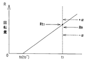
- FIG. 3 show the relationship of screw tightening pass / fail judgment based on the detected value characteristic of the rotation amount in the electric motor during the clutch operation by the automatic screw tightening control method according to the present invention, and set the target rotation amount as Rm ⁇ ⁇ . It is explanatory drawing which shows the proper screw fastening state in the case of having carried out.
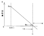
- FIG. 2 and FIG. 3 show the relationship of screw tightening pass / fail judgment based on the detected value characteristic of the rotation amount in the electric motor during clutch operation by the automatic screw tightening control method according to the present invention, and set the target rotation amount to 0 ⁇ ⁇ . It is explanatory drawing which shows the proper screw fastening state in the case of having carried out.
- FIG. 2 and FIG. 3 show the relationship of screw tightening pass / fail judgment based on the detected value characteristic of the rotation amount in the electric motor during clutch operation by the automatic screw tightening control method according to the present invention, and set the target rotation amount to 0 ⁇ ⁇ . It is explanatory drawing
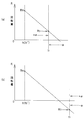
- FIG. 5 is an explanatory diagram showing a defective screw tightening state when the amount of rotation is smaller than the target amount of rotation Rm ⁇ ⁇ (including the allowable range).
- (b) is an explanatory view showing a defective screw tightening state when the rotation amount is larger than the target rotation amount Rm ⁇ ⁇ (including the allowable range).
- FIG. 6A is an explanatory diagram showing a defective screw tightening state when the amount of rotation is larger than the target amount of rotation 0 ⁇ ⁇ (including the allowable range), in the same screw tightening quality determination relationship as in the case shown in FIG. 6.
- (b) is an explanatory view showing a defective screw tightening state when the rotation amount is smaller than the target rotation amount 0 ⁇ ⁇ (including the allowable range).
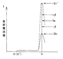
- FIG. 3 and FIG. 4 show the relationship of the screw tightening pass / fail judgment based on the detected value characteristic of the load current value in the electric motor during the clutch operation by the automatic screw tightening control method according to the present invention, and an appropriate screw tightening state.
- FIG. FIG. 10 is an explanatory diagram showing a screw tightening pass / fail judgment similar to that shown in FIG. 9 and showing a defective screw tightening state of a load current value. It is explanatory drawing which shows the schematic structure which shows another Example of the apparatus which implements the screw fastening control method which concerns on this invention, and its control system.
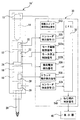
- FIG. 1 is a schematic configuration explanatory view showing an embodiment of an apparatus for carrying out an automatic screw tightening control method according to the present invention. That is, in FIG. 1, reference numeral 10 indicates an electric screwdriver. An electric motor 12, a drive switch 13 for driving the electric motor 12, and a drive output of the electric motor 12 are provided in a grip portion of the electric screwdriver 10. A speed reduction mechanism 16 and a clutch mechanism 18 coupled to a shaft (not shown) are respectively incorporated, and a driver bit 20 is coupled via the clutch mechanism 18.
- the switch operating member 14 that operates the drive switch 13 of the electric motor 12, the electric motor control circuit 22 that performs drive control and stop control of the electric motor 12, and the clutch operation of the clutch mechanism 18.
- a clutch operation detection sensor 28 for detection is provided.
- the electric motor control circuit 22 is provided with a rotation amount detecting means 24 for detecting the rotation amount of the precursor electric motor 12.
- load current detection means 26 for detecting the load current obtained in the electric motor 12 based on the load torque (reaction force) applied to the driver bit 20 is appropriately provided.
- a brushless motor can be suitably used as the electric motor 12.
- the switch operating member 14 for operating the drive switch 13 to drive the electric motor 12 can be configured as a known lever member provided on the outer periphery of the grip portion of the electric driver 10, for example.
- the rotation amount detection means 24 for detecting the rotation amount of the electric motor 12 counts the pulses generated at the time of magnetic pole detection with respect to the Hall element that detects the magnetic pole of the rotor in the brushless motor. It can be provided as a means. In this case, the count number of the pulses detected by the rotation amount detection means 24 can be detected and recorded as a rotation amount correlated with the screw tightening rotation amount in the screw tightening operation accompanying the rotation of the driver bit 20.
- the load current detecting means 26 for detecting the load current of the electric motor 12 can be provided as means for detecting the load current in the power supply circuit of the electric motor 12.
- the detected load current value of the electric motor 12 can be detected and recorded as a load current value correlated with a screw tightening torque value in the screw tightening operation accompanying the rotation of the driver bit 20.
- a clutch plate is attached to the output shaft of the speed reduction mechanism 16, and a clutch ball is elastically engaged with the clutch plate in the axial direction.
- a load torque (reaction force) above a certain level is applied to the output shaft, the clutch plate gets over the clutch ball, and the transmission of the rotational driving force to the bit holder that engages and holds the driver bit 20 is cut off.
- the screw can be tightened with a preset torque.
- the screw tightening torque can be set by appropriately adjusting the elasticity.
- the clutch operation detection sensor 28 for detecting the clutch operation of the clutch mechanism 18 includes, for example, a limit switch that operates by displacement of the clutch plate at the time of clutch operation, and an internal that constitutes the deceleration mechanism 16 that idles at the time of clutch operation. It can be configured by a known means such as a magnetic sensor for detecting the rotation of the gear.
- the control unit 30 is provided, and when the CPU 32 starts screw tightening work on the electric motor control circuit 22 provided in the electric motor 12 in the electric driver 10, the switch operation member is provided.
- a drive switch operation signal S13 obtained by the operation of the drive switch 13 operated by 14 is input, and based on this drive switch operation signal S13, a motor drive control signal S22a is output and input to the electric motor control circuit 22.
- the drive control of the electric motor 12 is performed.
- the CPU 32 detects the rotation amount detected by the rotation amount detection means 24 at the driving start time t0 of the electric motor 12 accompanying the start of the screw tightening operation. Based on the detection signal S24, the rotation amount Rt of the electric motor 12 is set to be detected and recorded.
- the driving start time t0 ⁇ ⁇ of the electric motor 12 accompanying the start of the screw tightening operation is proportional to the screw tightening torque value based on the load current detection signal S26 detected by the load current detecting means 26.
- the load current value It is set to be detected and recorded.
- the CPU 32 detects the amount of rotation of the electric motor 12 at the clutch operation time point t1 obtained based on the clutch operation detection signal S28 detected by the clutch operation detection sensor 28 at the clutch operation time point of the clutch mechanism 18.
- setting of a target rotation amount Rm ⁇ ⁇ ( ⁇ ⁇ is an allowable range) described later and a rotation amount Rt1 ⁇ ⁇ for comparison with the target rotation amount Rm ⁇ ⁇ is set to be detected and recorded.
- the load current proportional to the screw tightening torque value at the clutch operation time point t1t obtained based on the clutch operation detection signal S28 detected by the clutch operation detection sensor 28 at the clutch operation time point of the clutch mechanism 18.
- a setting of a target load current value Im ⁇ ⁇ ( ⁇ ⁇ is an allowable range) described later and a load current value It1t for comparison with the target load current value Im ⁇ ⁇ are detected and recorded.
- the motor stop control signal S22b is output and input to the electric motor control circuit 22 via the CPU 32, and the electric motor 12 stop control is performed.
- the CPU 32 of the control unit 30 compares the rotation amount Rt1 detected at the clutch operation time t1 with the preset target rotation amount Rm ⁇ ⁇ , When it is determined whether the screw tightening state is good and / or, by comparing the load current value It1 detected at the clutch operation time t1 with a preset target load current value Im ⁇ ⁇ , the screw tightening state When the quality is determined, the determination content is appropriately displayed on the display device 40 by any one of the screw tightening determination signals S40 output from the CPU 32.
- the CPU 32 calculates the rotation amount Rt of the electric motor 12 based on the rotation amount detection signal S24 detected in advance by the rotation amount detection means 24. It is set to detect and record together with the driving start time t0 (STEP-1, STEP-2).
- the predetermined screw tightening operation by the electric screwdriver 10 when the predetermined screw tightening operation by the electric screwdriver 10 is performed, the predetermined screw tightening operation is performed in advance, so that the screw tightening is started from the screw tightening start time t0-1 (STEP-1).
- the rotation amount Rm of the electric motor 12 until the clutch operation time t1 by the clutch mechanism 18 upon completion of the rotation is detected by the rotation amount detection means 24 (STEP-2), recorded in the CPU 32 of the controller 30, and the target rotation
- An amount Rm ⁇ ⁇ ( ⁇ ⁇ is an allowable range) is set in the CPU 32 (STEP-3).
- the rotation amount Rt of the electric motor 12 is based on the rotation amount detection signal S24 detected by the rotation amount detection means 24 at the start (STEP-1 and STEP-4) of the screw tightening operation accompanying the driving of the electric driver 10.
- the CPU 32 detects and records the rotation amount Rt of the electric motor 12 during the actual screw tightening operation after the driver bit 20 comes into contact with the object to be screwed, it is accurate. The amount of rotation can be detected.
- a support shaft that supports the driver bit 20 is coupled by a shaft joint so as to be elastically displaceable in the axial direction, and a magnet is provided at a displacement portion of the support shaft. It can be set as the structure which has arrange
- the rotation amount Rt1 of the electric motor 12 sequentially detected from the screw tightening start time t0 to the clutch operation time t1 by a predetermined screw tightening operation is set to the target rotation amount Rm ⁇ ⁇ (the allowable range is set).
- the rotation amount Rt1 of the electric motor detected from the set value of the target rotation amount Rm ⁇ ⁇ to the clutch operation time t1 in a predetermined screw tightening operation is sequentially added. And the detected value of the final rotation amount Rt1 can be compared with the set value of the target rotation amount Rm ⁇ ⁇ (including the allowable range).
- the rotation amount Rt1 ⁇ of the electric motor 12 sequentially detected from the screw tightening start time t0 to the clutch operation time t1 by a predetermined screw tightening operation is set as the first target rotation amount Rm ⁇ ⁇ (including the allowable range).
- the rotation amount of the electric motor 12 detected from the set value of the first target rotation amount Rm ⁇ ⁇ to the clutch operation time t1 in a predetermined screw tightening operation is sequentially subtracted.
- the final detection value of the rotation amount Rt1 is set to the second target rotation amount 0 ⁇ ⁇ ( It can also be configured to be compared with a set value (including an allowable range).
- the target rotation amount Rm ⁇ ⁇ or 0 ⁇ ⁇ (including the allowable range) is set and a predetermined screw tightening operation is performed
- the CPU 32 The clutch operation time t1 is detected and recorded, and the rotation amount Rt1 of the electric motor 12 at the clutch operation time t1 is detected and recorded (STEP-5). Therefore, the rotation amount Rt1 of the electric motor 12 detected at the clutch operation time t1 is compared with a preset target rotation amount Rm ⁇ ⁇ or 0 ⁇ ⁇ to compare the target rotation amount Rm ⁇ ⁇ or 0 ⁇ ⁇ . (Rm + ⁇ ⁇ Rt1 ⁇ Rm ⁇ or 0 + ⁇ ⁇ Rt1 ⁇ 0 ⁇ ) is determined (STEP-6).
- the screw tightening start time t0 for detecting the rotation amount Rt ⁇ of the electric motor 12 during the actual screw tightening operation after the driver bit 20 abuts against the object to be screwed is set ′.
- the rotation amount Rt1 of the electric motor 12 detected and recorded by the CPU 32 is compared with the target rotation amount Rm ⁇ ⁇ or 0 ⁇ ⁇ set in advance, respectively. If it complies with 0 ⁇ ⁇ (including the allowable range) (see FIGS. 5 and 6), it can be determined that the screw is properly tightened (STEP-7).
- the screw tightening state is bad. It can be determined (STEP-8).
- the control unit 30 can accurately record the number of screws determined to be appropriate in the screw tightening state, and the display unit 40 can be set to display the recorded contents. it can. Further, based on the rotation amount Rt1 of the electric motor 12 detected at the clutch operation time t1, the length of the screw that has been screwed is also accurately recorded by the control unit 30, and the recorded record is also recorded. The content can be set to be displayed on the display 40.
- the present control method can be configured such that the contents of each determination are appropriately displayed on the display 40 based on any one of the screw tightening determination signals S40 output from the CPU 32 (see FIG. 1).
- the rotation amount detection means 24 detects the rotation amount Rm of the electric motor 12 from the time point t0 (STEP-11) to the clutch operation time point t1 by the clutch mechanism 18 upon completion of screw tightening (STEP-12a). It is recorded in the CPU 32 of the device 30 and set in the CPU 32 as a target rotation amount Rm ⁇ ⁇ ( ⁇ ⁇ is an allowable range) (STEP-13a).
- the load current detection means 26 detects the load current value Im of the electric motor 12 from the start time t0 of the screw tightening to the clutch operation time t1 by the clutch mechanism 18 when the screw tightening is completed (STEP-12b ), And is recorded in the CPU 32 of the controller 30 and set in the CPU 32 as a target load current value Im ⁇ ⁇ ( ⁇ ⁇ is an allowable range) (STEP-13b).
- the clutch operation by the clutch mechanism 18 accompanying the completion of screw tightening from the screw tightening start time t0 (STEP-14).
- the rotation amount detection means 24 sequentially detects the rotation amount Rt ⁇ of the electric motor 12 up to the time point t1 (STEP-15a), and the rotation amount Rt1 detected at the clutch operation time point t1 is determined as the target rotation amount Rm ⁇ ⁇ (allowable). It is set so as to determine whether the screw tightening state is good or not (STEP-16a).
- the load current detection means 26 sequentially detects the load current value It from the start time t0 ⁇ of the screw tightening to the clutch operation time t1 ⁇ by the clutch mechanism 18 upon completion of the screw tightening (STEP-15b). By comparing the load current value It1 detected at the time t1 with the target load current value Im ⁇ ⁇ (including the allowable range) (STEP-16b), it is set to determine whether the screw tightening state is good or bad.
- the rotation amount Rt1 of the electric motor 12 detected at the clutch operation time point t1 ⁇ is compared with a preset target rotation amount Rm ⁇ ⁇ to determine whether or not it matches the target rotation amount Rm ⁇ ⁇ ( Rm + ⁇ ⁇ Rt1 ⁇ Rm ⁇ ) is determined (STEP-16a). Further, the load current value It1 detected at the clutch operation time t1 is compared with a preset target load current value Im ⁇ ⁇ , and whether or not the target load current value Im ⁇ ⁇ is satisfied (Im + ⁇ ⁇ It1 ⁇ Im ⁇ ) is determined (STEP-16b).
- the rotation amount Rt1 of the electric motor 12 is compared with the target rotation amount Rm ⁇ ⁇ to determine whether or not the target rotation amount Rm ⁇ ⁇ is satisfied (Rm + ⁇ ⁇ Rt1 ⁇ Rm ⁇ ).
- the means all the control methods (1) described above can be applied.
- the screw tightening state is It can be determined that it is appropriate (STEP-17). Therefore, in this case, the control unit 30 can accurately record the number of screws determined to be appropriate in the screw tightening state, and the display unit 40 can be set to display the recorded contents. it can. Further, based on the rotation amount Rt1 of the electric motor 12 detected at the clutch operation time t1, the length of the screw that has been screwed is also accurately recorded by the control unit 30, and the recorded record is also recorded. The content can be set to be displayed on the display 40.
- the load current value It1 detected and recorded at the clutch operation time t1t Becomes a state (It1 ⁇ Im ⁇ ⁇ ⁇ It1 ′) that does not conform to the target load current value Im ⁇ ⁇ including the allowable range (see FIG. 10).
- the electric motor 12 detected and recorded is recorded. Even if the rotation amount Rt1 is in a state that matches the target rotation amount Rm ⁇ ⁇ (Rm + ⁇ ⁇ Rt1 ⁇ Rm ⁇ ) (see FIG. 5), it can be determined that the screw tightening state is defective. (STEP-19).
- the load current value It1 detected and recorded at the clutch operating time t1 described above does not conform to the target load current value Im ⁇ ⁇ (It1 ⁇ Im ⁇ ⁇ ⁇ It1), and is also detected and recorded. If the rotation amount Rt1 of the electric motor 12 thus applied does not conform to the target rotation amount Rm ⁇ ⁇ (Rt1 ⁇ Rm ⁇ ⁇ ⁇ Rt1), it can be determined that the screw tightening state is defective (STEP). -18).
- the present control method (2) as in the case of the control method (1) described above, when the quality of the screw tightening state is determined, a determination display that can clearly distinguish between the appropriate determination and the defect determination is performed. Can do.
- the present control method can be configured such that the contents of each determination are appropriately displayed on the display 40 based on any one of the screw tightening determination signals S40 output from the CPU 32 (see FIG. 1).
- the screw tightening state is It can be determined that it is appropriate (STEP-27). Therefore, in this case, the control unit 30 can accurately record the number of screws determined to be appropriate in the screw tightening state, and the display unit 40 can be set to display the recorded contents. it can. Further, based on the rotation amount Rt1 of the electric motor 12 detected at the clutch operation time t1, the length of the screw that has been screwed is also accurately recorded by the control unit 30, and the recorded record is also recorded. The content can be set to be displayed on the display 40.
- the load current value It1 detected and recorded at the clutch operation time t1t. However, it becomes a state (It1 ⁇ Im ⁇ ⁇ ⁇ It1 ′) that does not conform to the target load current value Im ⁇ ⁇ including the allowable range (see FIG. 10), and it can be determined that the screw tightening state is defective ( (STEP-28).
- control method (3) as in the control methods (1) and (2) described above, when the quality of the screw tightening state is determined, the determination that can clearly distinguish between the appropriate determination and the defect determination. Display can be made.
- the present control method can be configured such that the contents of each determination are appropriately displayed on the display 40 based on any one of the screw tightening determination signals S40 output from the CPU 32 (see FIG. 1).
- the clutch operation time t1 by the clutch mechanism 18 accompanying the completion of screw tightening from the start time of screw tightening planned by a prior trial or the like based on the standard of the screw to be used in advance.
- the rotation amount Rm ′ of the electric motor 12 is set as the target rotation amount Rm ′ ⁇ ⁇ ( ⁇ ⁇ is an allowable range).
- the clutch mechanism 18 is used when the screw tightening is completed from the screw tightening start time t0 (t0 ′).
- the rotation amount detection means 24 sequentially detects the rotation amount of the electric motor 12 until the clutch operation time t1, and the rotation amount Rt1 detected at the clutch operation time t1 is the target rotation amount Rm ' ⁇ ⁇ (including the allowable range).
- the load current detection unit 26 detects the load current value It1 at the clutch operating time t1 and compares it with the target load current value Im ⁇ ⁇ . It can also be set as the structure set so.
- FIG. 11 is a schematic configuration explanatory view showing another embodiment of an apparatus for carrying out the automatic screw tightening control method according to the present invention.
- the same constituent elements as those of the apparatus of the embodiment shown in FIG. 1 described above have the same functions, and thus the same reference numerals are given and detailed descriptions thereof are omitted. .
- an electric motor other than the brushless motor can be applied as the electric motor 12, so that the rotation amount detecting means of the electric motor 12 is the driving shaft of the electric motor 12.
- the first encoder 25 made of a known rotary encoder is provided. Accordingly, in the present embodiment, the rotation amount of the electric motor 12 is determined as the rotation amount detection means by inputting the encoder detection signal S25 detected by the first encoder 25 to the CPU 32 of the control unit 30. Can be set. In this case, the encoder detection signal S25 detected by the first encoder 25 can be detected and recorded as a rotation amount correlated with a screw tightening rotation amount at the time of screw tightening of the driver bit 20 rotated by the electric motor 12. it can.
- the electric driver 10 ′ of the present embodiment can be configured such that a second encoder 29 composed of a known rotary encoder coupled to the driver bit 20 is attached as a rotation amount detection means of the driver bit 20. Accordingly, the rotation amount of the driver bit 20 can be set as rotation amount detection means by inputting the encoder detection signal S29 detected by the second encoder 29 to the CPU 32 of the control unit 30. . In this case, the encoder detection signal S29 detected by the second encoder 29 can be detected and recorded as a rotation amount correlated with the screw tightening rotation amount in the screw tightening operation by the rotation of the driver bit 20.
- the other configuration of the electric driver 10 ′ of the present embodiment is the same as that of the above-described embodiment, and therefore, the CPU 32 of the control unit 30 has a preset target rotation amount Rm ⁇ as in the above-described embodiment.
- the CPU 32 of the control unit 30 has a preset target rotation amount Rm ⁇ as in the above-described embodiment.
- the first encoder 25 or the second encoder 29 that detects a rotation amount correlated with the screw tightening rotation amount at the time of screw tightening of the driver bit 20, It is possible to detect and record the screw tightening start time t0 ′ when performing the screw tightening operation appropriately and easily.
- the start of screw tightening for a required screw hole is started.
- half of the trouble that causes screw tightening failure in the screw tightening operation can be confirmed and solved.
- screw tightening work (1) screw galling that occurs at the entrance by slant tightening to the pilot hole of the screw, and (2) workpiece and pilot hole generated when tightening tapping screw It is possible to confirm each of the screw floats that torque up before sitting due to a problem.
- the automatic screw tightening control method and apparatus when a plurality of preset screws are sequentially tightened in a required screw tightening operation, the above-described screw tightening for each screw is performed. At the same time as detecting and recording the judgment of the quality of the state, it is also possible to collect and record the number of screw tightening at the same time, facilitating the construction of a production line that performs various screw tightening operations and a production management system in those networks It becomes possible.
- the amount of rotation of the electric motor by the electric screwdriver is appropriately detected by using the clutch mechanism, so that the proper screw tightening can be performed. It is possible to easily and reliably determine the tightening completion (screw seating) state, and record or display each screw tightening state in relation to the number of screws to be subjected to many continuous screw tightening. Also, by detecting and recording the load current of the electric motor at the time of clutch operation in each screw tightening operation, the load current value at the time of clutch operation is the screw tightening torque value of the screw that has been completely screwed (seated), respectively.
- the present invention is not limited to such an embodiment.
- the present invention can be similarly applied to screw tightening control using a tapping screw or a drill screw or tapping screw processing.
- the time point (timing) at which the screw is seated in the screw tightening operation is set or configured to be detected by the clutch mechanism.
- the clutch mechanism for example, as the timing for detecting the rotation amount of the electric motor and the load current value, the detected rotation amount and load current value match the preset target rotation amount and target load current value, respectively. In this case, it can be configured to generate the required output signal and set the timing. Many other design changes can be made without departing from the spirit of the present invention.
Abstract
Description
前記電動ドライバーによる所定のねじ締め作業において、最初のねじ締め作業におけるねじ締めの開始時点からねじ締めの完了に伴う前記クラッチ機構によるクラッチ動作時点の電動モータの回転量を前記回転量検出手段により検出記録し、この検出記録された回転量を目標回転量(許容範囲を含む)として設定し、
その後における所定のねじ締め作業において、ねじ締めの開始時点からねじ締めの完了に伴う前記クラッチ機構によるクラッチ動作時点までの電動モータの回転量を前記回転量検出手段により逐次検出し、前記クラッチ動作時点に検出された回転量を前記目標回転量(許容範囲を含む)と比較することにより、ねじ締め状態の良否を判定するように設定することを特徴とする。
前記電動ドライバーによる所定のねじ締め作業において、最初のねじ締め作業におけるねじ締めの開始時点からねじ締めの完了に伴う前記クラッチ機構によるクラッチ動作時点の電動モータの回転量を前記回転量検出手段により検出記録し、この検出記録された回転量を目標回転量(許容範囲を含む)として設定すると共に、前記負荷電流検出手段により検出される電動モータのねじ締めトルク値に比例する負荷電流値を検出記録し、この検出記録された負荷電流値を目標負荷電流値(許容範囲を含む)として設定し、
その後における所定のねじ締め作業において、ねじ締めの開始時点からねじ締めの完了に伴う前記クラッチ機構によるクラッチ動作時点までの電動モータの回転量を前記回転量検出手段により逐次検出し、前記クラッチ動作時点に検出された回転量を前記目標回転量(許容範囲を含む)と比較すると共に、ねじ締めの開始時点からねじ締めの完了に伴う前記クラッチ機構によるクラッチ動作時点までの負荷電流値を前記負荷電流検出手段により逐次検出し、前記クラッチ動作時点に検出された負荷電流値を前記目標負荷電流値(許容範囲を含む)と比較することにより、ねじ締め状態の良否を判定するように設定することを特徴とする。
前記電動ドライバーによるねじ締め作業において、最初のねじ締め作業におけるねじ締めの開始時点からねじ締めの完了に伴う前記クラッチ機構によるクラッチ動作時点の電動モータのねじ締めトルク値に比例する負荷電流値を前記負荷電流検出手段により検出記録し、この検出記録された負荷電流値を目標負荷電流値(許容範囲を含む)として設定し、
その後における所定のねじ締め作業において、ねじ締めの開始時点からねじ締めの完了に伴う前記クラッチ機構によるクラッチ動作時点までのねじ締め電動モータのトルク値に比例する負荷電流値を前記負荷電流検出手段により逐次検出し、前記クラッチ動作時点に検出された負荷電流値を前記目標負荷電流値(許容範囲を含む)と比較することにより、ねじ締め状態の良否を判定するように設定することを特徴とする。
前記電動ドライバーによる所定のねじ締め作業において、予め使用するねじの規格に基づいて予定されるねじ締めの開始時点からねじ締めの完了に伴う前記クラッチ機構によるクラッチ動作時点の電動モータの回転量を目標回転量(許容範囲を含む)として設定し、
所定のねじ締め作業において、ねじ締めの開始時点からねじ締めの完了に伴う前記クラッチ機構によるクラッチ動作時点までの電動モータの回転量を前記回転量検出手段により逐次検出し、前記クラッチ動作時点に検出された回転量を前記目標回転量(許容範囲を含む)と比較することにより、ねじ締め状態の良否を判定するように設定することを特徴とする。
前記電動ドライバーによる所定のねじ締め作業において、ねじ締めの開始時点からねじ締めの完了に伴う前記クラッチ機構によるクラッチ動作時点、および/または、前記負荷電流検出手段により検出する負荷電流値が予め設定したねじ締めの完了に伴う目標負荷電流値に到達した時点において、前記前記回転量検出手段により逐次検出される電動モータの回転量を検出し、ねじ締めの完了に伴う前記目標負荷電流値(許容範囲を含む)と、前記電動モータの回転量として予め設定した目標回転量(許容範囲を含む)とを比較することにより、ねじ締め状態の良否を判定するように設定することを特徴とする。
前記電動ドライバーによる所定のねじ締め作業において、最初のねじ締め作業におけるねじ締めの開始時点からねじ締めの完了に伴う前記クラッチ機構によるクラッチ動作時点の電動モータの回転量を前記回転量検出手段により検出記録し、この検出記録された回転量を目標回転量(許容範囲を含む)として設定すると共に、
その後における所定のねじ締め作業において、ねじ締めの開始時点からねじ締めの完了に伴う前記クラッチ機構によるクラッチ動作時点までの電動モータの回転量を前記回転量検出手段により逐次検出し、前記クラッチ動作時点に検出された回転量を前記目標回転量(許容範囲を含む)と比較することにより、ねじ締め状態の良否を判定するように設定してなる制御部を設けることを特徴とする。
前記電動ドライバーによる所定のねじ締め作業において、最初のねじ締め作業におけるねじ締めの開始時点からねじ締めの完了に伴う前記クラッチ機構によるクラッチ動作時点の電動モータの回転量を前記回転量検出手段により検出記録し、この検出記録された回転量を目標回転量(許容範囲を含む)として設定すると共に、前記負荷電流検出手段により検出される電動モータのねじ締めトルク値に比例する負荷電流値を検出記録し、この検出記録された負荷電流値を目標負荷電流値(許容範囲を含む)として設定すると共に、
その後における所定のねじ締め作業において、ねじ締めの開始時点からねじ締めの完了に伴う前記クラッチ機構によるクラッチ動作時点までの電動モータの回転量を前記回転量検出手段により逐次検出し、前記クラッチ動作時点に検出された回転量を前記目標回転量(許容範囲を含む)と比較すると共に、ねじ締めの開始時点からねじ締めの完了に伴う前記クラッチ機構によるクラッチ動作時点までの負荷電流値を前記負荷電流検出手段により逐次検出し、前記クラッチ動作時点に検出された負荷電流値を前記目標負荷電流値(許容範囲を含む)と比較することにより、ねじ締め状態の良否を判定するように設定してなる制御部を設けることを特徴とする。
前記電動ドライバーによるねじ締め作業において、最初のねじ締め作業におけるねじ締めの開始時点からねじ締めの完了に伴う前記クラッチ機構によるクラッチ動作時点の電動モータのねじ締めトルク値に比例する負荷電流値を前記負荷電流検出手段により検出記録し、この検出記録された負荷電流値を目標負荷電流値(許容範囲を含む)として設定すると共に、
その後における所定のねじ締め作業において、ねじ締めの開始時点からねじ締めの完了に伴う前記クラッチ機構によるクラッチ動作時点までのねじ締め電動モータのトルク値に比例する負荷電流値を前記負荷電流検出手段により逐次検出し、前記クラッチ動作時点に検出された負荷電流値を前記目標負荷電流値(許容範囲を含む)と比較することにより、ねじ締め状態の良否を判定するように設定してなる制御部を設けることを特徴とする。
前記電動ドライバーによる所定のねじ締め作業において、予め使用するねじの規格に基づいて予定されるねじ締めの開始時点からねじ締めの完了に伴う前記クラッチ機構によるクラッチ動作時点の電動モータの回転量を目標回転量(許容範囲を含む)として設定すると共に、
所定のねじ締め作業において、ねじ締めの開始時点からねじ締めの完了に伴う前記クラッチ機構によるクラッチ動作時点までの電動モータの回転量を前記回転量検出手段により逐次検出し、前記クラッチ動作時点に検出された回転量を前記目標回転量(許容範囲を含む)と比較することにより、ねじ締め状態の良否を判定するように設定してなる制御部を設けることを特徴とする。
図1は、本発明に係る自動ねじ締め制御方法を実施する装置の実施例を示す概略構成説明図である。すなわち、図1において、参照符号10は電動ドライバーを示し、この電動ドライバー10の把持部内に、電動モータ12と、この電動モータ12を駆動するための駆動スイッチ13と、前記電動モータ12の駆動出力軸(図示せず)に結合される減速機構16およびクラッチ機構18とを、それぞれ内蔵し、前記クラッチ機構18を介してドライバービット20を結合した構成からなる。
本制御方法(1)において、所要のねじ締め作業を開始するに際しては、スイッチ操作部材14を操作することにより駆動スイッチ13を作動し、前記電動モータ制御回路22にモータ駆動制御信号S22a が入力されて、電動モータ12の駆動制御が行われ、電動ドライバー10の駆動が開始される(図1、図2参照)。
本制御方法(2)においては、前記制御方法(1)と同様にして、電動ドライバー10の駆動に伴うねじ締め作業の開始に際して、予め前記回転量検出手段24により検出される回転量検出信号S24に基づいて電動モータ12の回転量Rt を、CPU32において電動モータ駆動開始時点t0 と共に検出記録する(STEP-11、STEP-12a)と共に、さらに負荷電流検出手段26により検出されるねじ締めトルク値に比例する負荷電流値It を、CPU32においてねじ締め開始時点t0 と共に検出記録する(STEP-11、STEP-12b)ように設定する(図1、図3参照)。
本制御方法(3)においては、前記回転量検出手段24を設けない場合であって、電動ドライバー10の駆動に伴うねじ締め作業の開始に際して、予め負荷電流検出手段26により検出されるねじ締めトルク値に比例する負荷電流値It を、CPU32においてねじ締め開始タイミングt0 と共に検出記録する(STEP-21、STEP-22)ように設定する(図1、図4参照)。
本制御方法(4)は、前述した自動ねじ締め制御方法(1)および(2)において行っている、回転量検出手段24による目標回転量の設定方法に代えて、簡便に目標回転量の設定を行うようにした自動ねじ締め制御方法である。すなわち、前述した自動ねじ締め制御方法(1)および(2)においては、図2に示すように、回転量検出手段24による目標回転量の設定に際して、予め電動ドライバー10の駆動による所定のねじ締め作業において、ねじ締めの開始時点t0 (STEP-1)からねじ締めの完了に伴う前記クラッチ機構18によるクラッチ動作時点t1 までの電動モータ12の回転量Rmを前記回転量検出手段24により検出して(STEP-2)、制御器30のCPU32に記録し、目標回転量Rm±α(±αは許容範囲)として前記CPU32に設定するものである(STEP-3)。
図11は、本発明に係る自動ねじ締め制御方法を実施する装置の別の実施例を示す概略構成説明図である。なお、説明の便宜上、前述した図1に示す実施例の装置と、同一の構成要素については、それぞれ同一の機能を有することから、同一の参照符号を付し、それらの詳細な説明は省略する。
13 駆動スイッチ 14 スイッチ操作部材
16 減速機構 18 クラッチ機構
20 ドライバービット 22 電動モータ制御回路
24 回転量検出手段 25 第1のエンコーダ(回転量検出手段)
26 負荷電流検出手段 28 クラッチ動作検出センサ
29 第2のエンコーダ(回転量検出手段)
30 制御部 32 CPU
40 表示器 S13 駆動スイッチ操作信号
S22a モータ駆動制御信号 S22b モータ停止制御信号
S24 回転量検出信号 S25 エンコーダ検出信号
S26 負荷電流検出信号 S28 クラッチ動作検出信号
S29 エンコーダ検出信号 S40 ねじ締め状態判定信号
Rm±α 目標回転量(許容範囲を含む)
Im±β 目標負荷電流値(許容範囲を含む)
t0 電動モータ駆動開始時点/ねじ締め開始時点
t0´ (プッシュ操作スイッチによる)ねじ締め開始時点
t1 クラッチ動作時点
Rt1 クラッチ動作時点または不動作時点の回転量
It1、It1´ クラッチ動作時点の負荷電流検出値
Claims (19)
- 電動モータと、この電動モータを駆動するための駆動スイッチと、前記電動モータの駆動出力軸に減速機構およびクラッチ機構を介して結合されるドライバービットとを備え、前記駆動スイッチを操作するスイッチ操作部材と、前記クラッチ機構のクラッチ動作を検出するクラッチ動作検出センサと、前記電動モータの駆動および停止制御を行う電動モータ制御回路と、前記電動モータの回転量を検出する回転量検出手段とを、それぞれ設けた電動ドライバーを使用し、
前記電動ドライバーによる所定のねじ締め作業において、最初のねじ締め作業におけるねじ締めの開始時点からねじ締めの完了に伴う前記クラッチ機構によるクラッチ動作時点の電動モータの回転量を前記回転量検出手段により検出記録し、この検出記録された回転量を目標回転量(許容範囲を含む)として設定し、
その後における所定のねじ締め作業において、ねじ締めの開始時点からねじ締めの完了に伴う前記クラッチ機構によるクラッチ動作時点までの電動モータの回転量を前記回転量検出手段により逐次検出し、前記クラッチ動作時点に検出された回転量を前記目標回転量(許容範囲を含む)と比較することにより、ねじ締め状態の良否を判定するように設定することを特徴とする自動ねじ締め制御方法。 - 電動モータと、この電動モータを駆動するための駆動スイッチと、前記電動モータの駆動出力軸に減速機構およびクラッチ機構を介して結合されるドライバービットとを備え、前記駆動スイッチを操作するスイッチ操作部材と、前記クラッチ機構のクラッチ動作を検出するクラッチ動作検出センサと、前記電動モータの駆動および停止制御を行う電動モータ制御回路と、前記電動モータの回転量を検出する回転量検出手段と、前記電動モータ制御回路において前記ドライバービットに付与される負荷トルク(反力)に基づく電動モータにおいて得られる負荷電流を検出する負荷電流検出手段と、をそれぞれ設けた電動ドライバーを使用し、
前記電動ドライバーによる所定のねじ締め作業において、最初のねじ締め作業におけるねじ締めの開始時点からねじ締めの完了に伴う前記クラッチ機構によるクラッチ動作時点の電動モータの回転量を前記回転量検出手段により検出記録し、この検出記録された回転量を目標回転量(許容範囲を含む)として設定すると共に、前記負荷電流検出手段により検出される電動モータのねじ締めトルク値に比例する負荷電流値を検出記録し、この検出記録された負荷電流値を目標負荷電流値(許容範囲を含む)として設定し、
その後における所定のねじ締め作業において、ねじ締めの開始時点からねじ締めの完了に伴う前記クラッチ機構によるクラッチ動作時点までの電動モータの回転量を前記回転量検出手段により逐次検出し、前記クラッチ動作時点に検出された回転量を前記目標回転量(許容範囲を含む)と比較すると共に、ねじ締めの開始時点からねじ締めの完了に伴う前記クラッチ機構によるクラッチ動作時点までの負荷電流値を前記負荷電流検出手段により逐次検出し、前記クラッチ動作時点に検出された負荷電流値を前記目標負荷電流値(許容範囲を含む)と比較することにより、ねじ締め状態の良否を判定するように設定することを特徴とする自動ねじ締め制御方法。 - 電動モータと、この電動モータを駆動するための駆動スイッチと、前記電動モータの駆動出力軸に減速機構およびクラッチ機構を介して結合されるドライバービットとを備え、前記駆動スイッチを操作するスイッチ操作部材と、前記クラッチ機構のクラッチ動作を検出するクラッチ動作検出センサと、前記電動モータの駆動および停止制御を行う電動モータ制御回路と、前記電動モータ制御回路において前記ドライバービットに付与される負荷トルク(反力)に基づく電動モータにおいて得られる負荷電流を検出する負荷電流検出手段とを、それぞれ設けた電動ドライバーを使用し、
前記電動ドライバーによるねじ締め作業において、最初のねじ締め作業におけるねじ締めの開始時点からねじ締めの完了に伴う前記クラッチ機構によるクラッチ動作時点の電動モータのねじ締めトルク値に比例する負荷電流値を前記負荷電流検出手段により検出記録し、この検出記録された負荷電流値を目標負荷電流値(許容範囲を含む)として設定し、
その後における所定のねじ締め作業において、ねじ締めの開始時点からねじ締めの完了に伴う前記クラッチ機構によるクラッチ動作時点までのねじ締め電動モータのトルク値に比例する負荷電流値を前記負荷電流検出手段により逐次検出し、前記クラッチ動作時点に検出された負荷電流値を前記目標負荷電流値(許容範囲を含む)と比較することにより、ねじ締め状態の良否を判定するように設定することを特徴とする自動ねじ締め制御方法。 - 電動モータと、この電動モータを駆動するための駆動スイッチと、前記電動モータの駆動出力軸に減速機構およびクラッチ機構を介して結合されるドライバービットとを備え、前記駆動スイッチを操作するスイッチ操作部材と、前記クラッチ機構のクラッチ動作を検出するクラッチ動作検出センサと、前記電動モータの駆動および停止制御を行う電動モータ制御回路と、前記電動モータの回転量を検出する回転量検出手段とを、それぞれ設けた電動ドライバーを使用し、
前記電動ドライバーによる所定のねじ締め作業において、予め使用するねじの規格に基づいて予定されるねじ締めの開始時点からねじ締めの完了に伴う前記クラッチ機構によるクラッチ動作時点の電動モータの回転量を目標回転量(許容範囲を含む)として設定し、
所定のねじ締め作業において、ねじ締めの開始時点からねじ締めの完了に伴う前記クラッチ機構によるクラッチ動作時点までの電動モータの回転量を前記回転量検出手段により逐次検出し、前記クラッチ動作時点に検出された回転量を前記目標回転量(許容範囲を含む)と比較することにより、ねじ締め状態の良否を判定するように設定することを特徴とする自動ねじ締め制御方法。 - 所定のねじ締め作業において、ねじ締め開始時点からクラッチ動作時点までに逐次検出される電動モータの回転量を前記目標回転量(許容範囲を含む)と比較する場合において、前記目標回転量の設定値から所定のねじ締め作業においてクラッチ動作時点までに検出される電動モータの回転量を、逐次加算するように演算して、最終的な回転量の検出値を前記目標回転量(許容範囲を含む)の設定値と比較するように構成することを特徴とする請求項1、2または4記載の自動ねじ締め制御方法。
- 所定のねじ締め作業において、ねじ締め開始時点からクラッチ動作時点までに逐次検出される電動モータの回転量を前記第1の目標回転量(許容範囲を含む)と比較する場合において、前記第1の目標回転量の設定値から所定のねじ締め作業においてクラッチ動作時点までに検出される電動モータの回転量を逐次減算するように演算し、最終的に第2の目標回転量を0(許容範囲を含む)となるように設定して、最終的な回転量の検出値を前記第2の目標回転量(許容範囲を含む)の設定値と比較するように構成することを特徴とする請求項1、2または4記載の自動ねじ締め制御方法。
- 前記電動ドライバーにおいて、ねじの取付け対象物に対するドライバービットの当接時における軸方向の変位によって作動するプッシュ操作スイッチまたはエンコーダを設けて、前記プッシュ操作スイッチまたはエンコーダの動作信号により、ねじ締め作業を行う際のねじ締め開始時点として設定することを特徴とする請求項1ないし6のいずれかに記載の自動ねじ締め制御方法。
- 前記クラッチ動作時点に検出される電動モータの回転量が、予め設定した目標回転量(許容範囲を含む)に適合した場合、および/または、前記クラッチ動作時点に検出される負荷電流検出値が、予め設定した目標負荷電流値(許容範囲を含む)に適合した場合には、ねじ締め状態を適正と判定するように設定することを特徴とする請求項1ないし6のいずれかに記載の自動ねじ締め制御方法。
- 前記クラッチ動作時点または不動作時の電動モータの回転量が、予め設定した目標回転量(許容範囲を含む)に適合しない場合、および/または、前記クラッチ動作時点での電動モータのねじ締めトルク値に比例する負荷電流検出値が、予め設定した目標負荷電流値(許容範囲を含む)に適合しない場合には、ねじ締め状態を不良と判定するように設定することを特徴とする請求項1ないし6のいずれかに記載の自動ねじ締め制御方法。
- 前記クラッチ動作時点に検出される電動モータの回転量および/または前記クラッチ動作時点に検出される負荷電流検出値が、それぞれ目標回転量(許容範囲を含む)および/または目標負荷電流値(許容範囲を含む)に適合し、ねじ締め状態を適正と判定されたねじの本数および/またはねじの長さ寸法を検出記録するように設定したことを特徴とする請求項1ないし6のいずれかに記載の自動ねじ締め制御方法。
- 前記クラッチ動作時点に検出されるねじ締め状態を適正または不良と判定した場合に、それぞれの状態を区別して表示器において表示するように設定することを特徴とする請求項1ないし10のいずれかに記載の自動ねじ締め制御方法。
- 電動モータと、この電動モータを駆動するための駆動スイッチと、前記電動モータの駆動出力軸に減速機構およびクラッチ機構を介して結合されるドライバービットとを備え、前記駆動スイッチを操作するスイッチ操作部材と、前記クラッチ機構のクラッチ動作を検出するクラッチ動作検出センサと、前記電動モータの駆動および停止制御を行う電動モータ制御回路と、前記電動モータの回転量を検出する回転量検出手段と、前記電動モータ制御回路において前記ドライバービットに付与される負荷トルク(反力)に基づく電動モータにおいて得られる負荷電流を検出する負荷電流検出手段と、をそれぞれ設けた電動ドライバーを使用し、
前記電動ドライバーによる所定のねじ締め作業において、ねじ締めの開始時点からねじ締めの完了に伴う前記クラッチ機構によるクラッチ動作時点、および/または、前記負荷電流検出手段により検出する負荷電流値が予め設定したねじ締めの完了に伴う目標負荷電流値に到達した時点において、前記前記回転量検出手段により逐次検出される電動モータの回転量を検出し、ねじ締めの完了に伴う前記目標負荷電流値(許容範囲を含む)と、前記電動モータの回転量として予め設定した目標回転量(許容範囲を含む)とを比較することにより、ねじ締め状態の良否を判定するように設定することを特徴とする自動ねじ締め制御方法。 - 電動モータと、この電動モータを駆動するための駆動スイッチと、前記電動モータの駆動出力軸に減速機構およびクラッチ機構を介して結合されるドライバービットとを備え、前記駆動スイッチを操作するスイッチ操作部材と、前記クラッチ機構のクラッチ動作を検出するクラッチ動作検出センサと、前記電動モータの駆動および停止制御を行う電動モータ制御回路と、前記電動モータの回転量を検出する回転量検出手段とを、それぞれ設けた電動ドライバーからなり、
前記電動ドライバーによる所定のねじ締め作業において、最初のねじ締め作業におけるねじ締めの開始時点からねじ締めの完了に伴う前記クラッチ機構によるクラッチ動作時点の電動モータの回転量を前記回転量検出手段により検出記録し、この検出記録された回転量を目標回転量(許容範囲を含む)として設定すると共に、
その後における所定のねじ締め作業において、ねじ締めの開始時点からねじ締めの完了に伴う前記クラッチ機構によるクラッチ動作時点までの電動モータの回転量を前記回転量検出手段により逐次検出し、前記クラッチ動作時点に検出された回転量を前記目標回転量(許容範囲を含む)と比較することにより、ねじ締め状態の良否を判定するように設定してなる制御部を設けることを特徴とする自動ねじ締め制御装置。 - 電動モータと、この電動モータを駆動するための駆動スイッチと、前記電動モータの駆動出力軸に減速機構およびクラッチ機構を介して結合されるドライバービットとを備え、前記駆動スイッチを操作するスイッチ操作部材と、前記クラッチ機構のクラッチ動作を検出するクラッチ動作検出センサと、前記電動モータの駆動および停止制御を行う電動モータ制御回路と、前記電動モータの回転量を検出する回転量検出手段と、前記電動モータ制御回路において前記ドライバービットに付与される負荷トルク(反力)に基づく電動モータにおいて得られる負荷電流を検出する負荷電流検出手段と、をそれぞれ設けた電動ドライバーからなり、
前記電動ドライバーによる所定のねじ締め作業において、最初のねじ締め作業におけるねじ締めの開始時点からねじ締めの完了に伴う前記クラッチ機構によるクラッチ動作時点の電動モータの回転量を前記回転量検出手段により検出記録し、この検出記録された回転量を目標回転量(許容範囲を含む)として設定すると共に、前記負荷電流検出手段により検出される電動モータのねじ締めトルク値に比例する負荷電流値を検出記録し、この検出記録された負荷電流値を目標負荷電流値(許容範囲を含む)として設定すると共に、
その後における所定のねじ締め作業において、ねじ締めの開始時点からねじ締めの完了に伴う前記クラッチ機構によるクラッチ動作時点までの電動モータの回転量を前記回転量検出手段により逐次検出し、前記クラッチ動作時点に検出された回転量を前記目標回転量(許容範囲を含む)と比較すると共に、ねじ締めの開始時点からねじ締めの完了に伴う前記クラッチ機構によるクラッチ動作時点までの負荷電流値を前記負荷電流検出手段により逐次検出し、前記クラッチ動作時点に検出された負荷電流値を前記目標負荷電流値(許容範囲を含む)と比較することにより、ねじ締め状態の良否を判定するように設定してなる制御部を設けることを特徴とする自動ねじ締め制御装置。 - 電動モータと、この電動モータを駆動するための駆動スイッチと、前記電動モータの駆動出力軸に減速機構およびクラッチ機構を介して結合されるドライバービットとを備え、前記駆動スイッチを操作するスイッチ操作部材と、前記クラッチ機構のクラッチ動作を検出するクラッチ動作検出センサと、前記電動モータの駆動および停止制御を行う電動モータ制御回路と、前記電動モータ制御回路において前記ドライバービットに付与される負荷トルク(反力)に基づく電動モータにおいて得られる負荷電流を検出する負荷電流検出手段とを、それぞれ設けた電動ドライバーからなり、
前記電動ドライバーによるねじ締め作業において、最初のねじ締め作業におけるねじ締めの開始時点からねじ締めの完了に伴う前記クラッチ機構によるクラッチ動作時点の電動モータのねじ締めトルク値に比例する負荷電流値を前記負荷電流検出手段により検出記録し、この検出記録された負荷電流値を目標負荷電流値(許容範囲を含む)として設定すると共に、
その後における所定のねじ締め作業において、ねじ締めの開始時点からねじ締めの完了に伴う前記クラッチ機構によるクラッチ動作時点までのねじ締め電動モータのトルク値に比例する負荷電流値を前記負荷電流検出手段により逐次検出し、前記クラッチ動作時点に検出された負荷電流値を前記目標負荷電流値(許容範囲を含む)と比較することにより、ねじ締め状態の良否を判定するように設定してなる制御部を設けることを特徴とする自動ねじ締め制御装置。 - 電動モータと、この電動モータを駆動するための駆動スイッチと、前記電動モータの駆動出力軸に減速機構およびクラッチ機構を介して結合されるドライバービットとを備え、前記駆動スイッチを操作するスイッチ操作部材と、前記クラッチ機構のクラッチ動作を検出するクラッチ動作検出センサと、前記電動モータの駆動および停止制御を行う電動モータ制御回路と、前記電動モータの回転量を検出する回転量検出手段とを、それぞれ設けた電動ドライバーからなり、
前記電動ドライバーによる所定のねじ締め作業において、予め使用するねじの規格に基づいて予定されるねじ締めの開始時点からねじ締めの完了に伴う前記クラッチ機構によるクラッチ動作時点の電動モータの回転量を目標回転量(許容範囲を含む)として設定すると共に、
所定のねじ締め作業において、ねじ締めの開始時点からねじ締めの完了に伴う前記クラッチ機構によるクラッチ動作時点までの電動モータの回転量を前記回転量検出手段により逐次検出し、前記クラッチ動作時点に検出された回転量を前記目標回転量(許容範囲を含む)と比較することにより、ねじ締め状態の良否を判定するように設定してなる制御部を設けることを特徴とする自動ねじ締め制御装置。 - 前記電動ドライバーにおいて、ねじの取付け対象物に対するドライバービットの当接時における軸方向の変位によって作動するプッシュ操作スイッチまたはエンコーダを設け、前記プッシュ操作スイッチまたはエンコーダの動作信号により、ねじ締め作業を行う際のねじ締め開始時点を設定するように構成することを特徴とする請求項13ないし16のいずれかに記載の自動ねじ締め制御装置。
- 前記制御部において、前記クラッチ動作時に検出される電動モータの回転量および/または前記クラッチ動作時に検出される負荷電流検出値が、それぞれ目標回転量(許容範囲を含む)および/または目標負荷電流値(許容範囲を含む)に適合し、ねじ締め状態を適正と判定されたねじの本数および/またはねじの長さ寸法を検出記録するように構成したことを特徴とする請求項13ないし16のいずれかに記載の自動ねじ締め制御装置。
- 前記制御部において得られるねじ締め状態の良否の判定結果に対して、それぞれの状態を区別して表示する表示器を設けることを特徴とする請求項13ないし18のいずれかに記載の自動ねじ締め制御装置。
Priority Applications (6)
| Application Number | Priority Date | Filing Date | Title |
|---|---|---|---|
| EP13849632.8A EP2913155B1 (en) | 2012-10-26 | 2013-09-25 | Automatic screw tightening control method and device |
| JP2014543202A JP6304661B2 (ja) | 2012-10-26 | 2013-09-25 | 自動ねじ締め制御方法および装置 |
| CN201380050036.4A CN104661796B (zh) | 2012-10-26 | 2013-09-25 | 自动螺钉拧紧控制方法及装置 |
| US14/434,064 US10471576B2 (en) | 2012-10-26 | 2013-09-25 | Automatic screw tightening control method and device |
| US16/565,757 US11130217B2 (en) | 2012-10-26 | 2019-09-10 | Automatic screw tightening control method and device |
| US17/405,896 US11433518B2 (en) | 2012-10-26 | 2021-08-18 | Automatic screw tightening control method and device |
Applications Claiming Priority (4)
| Application Number | Priority Date | Filing Date | Title |
|---|---|---|---|
| JP2012236697 | 2012-10-26 | ||
| JP2012-236697 | 2012-10-26 | ||
| JP2013-013207 | 2013-01-28 | ||
| JP2013013207 | 2013-01-28 |
Related Child Applications (2)
| Application Number | Title | Priority Date | Filing Date |
|---|---|---|---|
| US14/434,064 A-371-Of-International US10471576B2 (en) | 2012-10-26 | 2013-09-25 | Automatic screw tightening control method and device |
| US16/565,757 Continuation US11130217B2 (en) | 2012-10-26 | 2019-09-10 | Automatic screw tightening control method and device |
Publications (1)
| Publication Number | Publication Date |
|---|---|
| WO2014065066A1 true WO2014065066A1 (ja) | 2014-05-01 |
Family
ID=50544446
Family Applications (1)
| Application Number | Title | Priority Date | Filing Date |
|---|---|---|---|
| PCT/JP2013/075856 WO2014065066A1 (ja) | 2012-10-26 | 2013-09-25 | 自動ねじ締め制御方法および装置 |
Country Status (5)
| Country | Link |
|---|---|
| US (3) | US10471576B2 (ja) |
| EP (1) | EP2913155B1 (ja) |
| JP (1) | JP6304661B2 (ja) |
| CN (1) | CN104661796B (ja) |
| WO (1) | WO2014065066A1 (ja) |
Cited By (3)
| Publication number | Priority date | Publication date | Assignee | Title |
|---|---|---|---|---|
| CN104999267A (zh) * | 2015-08-24 | 2015-10-28 | 李宏伟 | 一种电动拧紧机工装 |
| JP6038397B1 (ja) * | 2015-05-26 | 2016-12-07 | 株式会社 エニイワイヤ | 電動ドライバ管理システム |
| TWI793967B (zh) * | 2022-01-10 | 2023-02-21 | 碩豐工業股份有限公司 | 離合型動力傳輸裝置及其轉速控制模組 |
Families Citing this family (379)
| Publication number | Priority date | Publication date | Assignee | Title |
|---|---|---|---|---|
| US9060770B2 (en) | 2003-05-20 | 2015-06-23 | Ethicon Endo-Surgery, Inc. | Robotically-driven surgical instrument with E-beam driver |
| US20070084897A1 (en) | 2003-05-20 | 2007-04-19 | Shelton Frederick E Iv | Articulating surgical stapling instrument incorporating a two-piece e-beam firing mechanism |
| US8215531B2 (en) | 2004-07-28 | 2012-07-10 | Ethicon Endo-Surgery, Inc. | Surgical stapling instrument having a medical substance dispenser |
| US11896225B2 (en) | 2004-07-28 | 2024-02-13 | Cilag Gmbh International | Staple cartridge comprising a pan |
| US7669746B2 (en) | 2005-08-31 | 2010-03-02 | Ethicon Endo-Surgery, Inc. | Staple cartridges for forming staples having differing formed staple heights |
| US10159482B2 (en) | 2005-08-31 | 2018-12-25 | Ethicon Llc | Fastener cartridge assembly comprising a fixed anvil and different staple heights |
| US11246590B2 (en) | 2005-08-31 | 2022-02-15 | Cilag Gmbh International | Staple cartridge including staple drivers having different unfired heights |
| US11484312B2 (en) | 2005-08-31 | 2022-11-01 | Cilag Gmbh International | Staple cartridge comprising a staple driver arrangement |
| US9237891B2 (en) | 2005-08-31 | 2016-01-19 | Ethicon Endo-Surgery, Inc. | Robotically-controlled surgical stapling devices that produce formed staples having different lengths |
| US7934630B2 (en) | 2005-08-31 | 2011-05-03 | Ethicon Endo-Surgery, Inc. | Staple cartridges for forming staples having differing formed staple heights |
| US20070106317A1 (en) | 2005-11-09 | 2007-05-10 | Shelton Frederick E Iv | Hydraulically and electrically actuated articulation joints for surgical instruments |
| US7845537B2 (en) | 2006-01-31 | 2010-12-07 | Ethicon Endo-Surgery, Inc. | Surgical instrument having recording capabilities |
| US11793518B2 (en) | 2006-01-31 | 2023-10-24 | Cilag Gmbh International | Powered surgical instruments with firing system lockout arrangements |
| US20110290856A1 (en) | 2006-01-31 | 2011-12-01 | Ethicon Endo-Surgery, Inc. | Robotically-controlled surgical instrument with force-feedback capabilities |
| US7753904B2 (en) | 2006-01-31 | 2010-07-13 | Ethicon Endo-Surgery, Inc. | Endoscopic surgical instrument with a handle that can articulate with respect to the shaft |
| US11278279B2 (en) | 2006-01-31 | 2022-03-22 | Cilag Gmbh International | Surgical instrument assembly |
| US20110024477A1 (en) | 2009-02-06 | 2011-02-03 | Hall Steven G | Driven Surgical Stapler Improvements |
| US8186555B2 (en) | 2006-01-31 | 2012-05-29 | Ethicon Endo-Surgery, Inc. | Motor-driven surgical cutting and fastening instrument with mechanical closure system |
| US20120292367A1 (en) | 2006-01-31 | 2012-11-22 | Ethicon Endo-Surgery, Inc. | Robotically-controlled end effector |
| US11224427B2 (en) | 2006-01-31 | 2022-01-18 | Cilag Gmbh International | Surgical stapling system including a console and retraction assembly |
| US8820603B2 (en) | 2006-01-31 | 2014-09-02 | Ethicon Endo-Surgery, Inc. | Accessing data stored in a memory of a surgical instrument |
| US8708213B2 (en) | 2006-01-31 | 2014-04-29 | Ethicon Endo-Surgery, Inc. | Surgical instrument having a feedback system |
| US8992422B2 (en) | 2006-03-23 | 2015-03-31 | Ethicon Endo-Surgery, Inc. | Robotically-controlled endoscopic accessory channel |
| US8322455B2 (en) | 2006-06-27 | 2012-12-04 | Ethicon Endo-Surgery, Inc. | Manually driven surgical cutting and fastening instrument |
| US10568652B2 (en) | 2006-09-29 | 2020-02-25 | Ethicon Llc | Surgical staples having attached drivers of different heights and stapling instruments for deploying the same |
| US8652120B2 (en) | 2007-01-10 | 2014-02-18 | Ethicon Endo-Surgery, Inc. | Surgical instrument with wireless communication between control unit and sensor transponders |
| US11291441B2 (en) | 2007-01-10 | 2022-04-05 | Cilag Gmbh International | Surgical instrument with wireless communication between control unit and remote sensor |
| US8684253B2 (en) | 2007-01-10 | 2014-04-01 | Ethicon Endo-Surgery, Inc. | Surgical instrument with wireless communication between a control unit of a robotic system and remote sensor |
| US11039836B2 (en) | 2007-01-11 | 2021-06-22 | Cilag Gmbh International | Staple cartridge for use with a surgical stapling instrument |
| US8540128B2 (en) | 2007-01-11 | 2013-09-24 | Ethicon Endo-Surgery, Inc. | Surgical stapling device with a curved end effector |
| US7438209B1 (en) | 2007-03-15 | 2008-10-21 | Ethicon Endo-Surgery, Inc. | Surgical stapling instruments having a releasable staple-forming pocket |
| US11857181B2 (en) | 2007-06-04 | 2024-01-02 | Cilag Gmbh International | Robotically-controlled shaft based rotary drive systems for surgical instruments |
| US8931682B2 (en) | 2007-06-04 | 2015-01-13 | Ethicon Endo-Surgery, Inc. | Robotically-controlled shaft based rotary drive systems for surgical instruments |
| US7753245B2 (en) | 2007-06-22 | 2010-07-13 | Ethicon Endo-Surgery, Inc. | Surgical stapling instruments |
| US11849941B2 (en) | 2007-06-29 | 2023-12-26 | Cilag Gmbh International | Staple cartridge having staple cavities extending at a transverse angle relative to a longitudinal cartridge axis |
| US8758391B2 (en) | 2008-02-14 | 2014-06-24 | Ethicon Endo-Surgery, Inc. | Interchangeable tools for surgical instruments |
| US9179912B2 (en) | 2008-02-14 | 2015-11-10 | Ethicon Endo-Surgery, Inc. | Robotically-controlled motorized surgical cutting and fastening instrument |
| RU2493788C2 (ru) | 2008-02-14 | 2013-09-27 | Этикон Эндо-Серджери, Инк. | Хирургический режущий и крепежный инструмент, имеющий радиочастотные электроды |
| US8636736B2 (en) | 2008-02-14 | 2014-01-28 | Ethicon Endo-Surgery, Inc. | Motorized surgical cutting and fastening instrument |
| US7819298B2 (en) | 2008-02-14 | 2010-10-26 | Ethicon Endo-Surgery, Inc. | Surgical stapling apparatus with control features operable with one hand |
| US8573465B2 (en) | 2008-02-14 | 2013-11-05 | Ethicon Endo-Surgery, Inc. | Robotically-controlled surgical end effector system with rotary actuated closure systems |
| US7866527B2 (en) | 2008-02-14 | 2011-01-11 | Ethicon Endo-Surgery, Inc. | Surgical stapling apparatus with interlockable firing system |
| US10390823B2 (en) | 2008-02-15 | 2019-08-27 | Ethicon Llc | End effector comprising an adjunct |
| US9386983B2 (en) | 2008-09-23 | 2016-07-12 | Ethicon Endo-Surgery, Llc | Robotically-controlled motorized surgical instrument |
| US9005230B2 (en) | 2008-09-23 | 2015-04-14 | Ethicon Endo-Surgery, Inc. | Motorized surgical instrument |
| US11648005B2 (en) | 2008-09-23 | 2023-05-16 | Cilag Gmbh International | Robotically-controlled motorized surgical instrument with an end effector |
| US8210411B2 (en) | 2008-09-23 | 2012-07-03 | Ethicon Endo-Surgery, Inc. | Motor-driven surgical cutting instrument |
| US8608045B2 (en) | 2008-10-10 | 2013-12-17 | Ethicon Endo-Sugery, Inc. | Powered surgical cutting and stapling apparatus with manually retractable firing system |
| US8517239B2 (en) | 2009-02-05 | 2013-08-27 | Ethicon Endo-Surgery, Inc. | Surgical stapling instrument comprising a magnetic element driver |
| BRPI1008667A2 (pt) | 2009-02-06 | 2016-03-08 | Ethicom Endo Surgery Inc | aperfeiçoamento do grampeador cirúrgico acionado |
| US8851354B2 (en) | 2009-12-24 | 2014-10-07 | Ethicon Endo-Surgery, Inc. | Surgical cutting instrument that analyzes tissue thickness |
| US8220688B2 (en) | 2009-12-24 | 2012-07-17 | Ethicon Endo-Surgery, Inc. | Motor-driven surgical cutting instrument with electric actuator directional control assembly |
| US8783543B2 (en) | 2010-07-30 | 2014-07-22 | Ethicon Endo-Surgery, Inc. | Tissue acquisition arrangements and methods for surgical stapling devices |
| US8740038B2 (en) | 2010-09-30 | 2014-06-03 | Ethicon Endo-Surgery, Inc. | Staple cartridge comprising a releasable portion |
| US11298125B2 (en) | 2010-09-30 | 2022-04-12 | Cilag Gmbh International | Tissue stapler having a thickness compensator |
| US11925354B2 (en) | 2010-09-30 | 2024-03-12 | Cilag Gmbh International | Staple cartridge comprising staples positioned within a compressible portion thereof |
| US9566061B2 (en) | 2010-09-30 | 2017-02-14 | Ethicon Endo-Surgery, Llc | Fastener cartridge comprising a releasably attached tissue thickness compensator |
| US9241714B2 (en) | 2011-04-29 | 2016-01-26 | Ethicon Endo-Surgery, Inc. | Tissue thickness compensator and method for making the same |
| US10945731B2 (en) | 2010-09-30 | 2021-03-16 | Ethicon Llc | Tissue thickness compensator comprising controlled release and expansion |
| US9629814B2 (en) | 2010-09-30 | 2017-04-25 | Ethicon Endo-Surgery, Llc | Tissue thickness compensator configured to redistribute compressive forces |
| US11812965B2 (en) | 2010-09-30 | 2023-11-14 | Cilag Gmbh International | Layer of material for a surgical end effector |
| US9386988B2 (en) | 2010-09-30 | 2016-07-12 | Ethicon End-Surgery, LLC | Retainer assembly including a tissue thickness compensator |
| US8695866B2 (en) | 2010-10-01 | 2014-04-15 | Ethicon Endo-Surgery, Inc. | Surgical instrument having a power control circuit |
| AU2012250197B2 (en) | 2011-04-29 | 2017-08-10 | Ethicon Endo-Surgery, Inc. | Staple cartridge comprising staples positioned within a compressible portion thereof |
| US11207064B2 (en) | 2011-05-27 | 2021-12-28 | Cilag Gmbh International | Automated end effector component reloading system for use with a robotic system |
| US9072535B2 (en) | 2011-05-27 | 2015-07-07 | Ethicon Endo-Surgery, Inc. | Surgical stapling instruments with rotatable staple deployment arrangements |
| US9044230B2 (en) | 2012-02-13 | 2015-06-02 | Ethicon Endo-Surgery, Inc. | Surgical cutting and fastening instrument with apparatus for determining cartridge and firing motion status |
| BR112014024102B1 (pt) | 2012-03-28 | 2022-03-03 | Ethicon Endo-Surgery, Inc | Conjunto de cartucho de prendedores para um instrumento cirúrgico, e conjunto de atuador de extremidade para um instrumento cirúrgico |
| MX353040B (es) | 2012-03-28 | 2017-12-18 | Ethicon Endo Surgery Inc | Unidad retenedora que incluye un compensador de grosor de tejido. |
| JP6105041B2 (ja) | 2012-03-28 | 2017-03-29 | エシコン・エンド−サージェリィ・インコーポレイテッドEthicon Endo−Surgery,Inc. | 低圧環境を画定するカプセルを含む組織厚コンペンセーター |
| US9101358B2 (en) | 2012-06-15 | 2015-08-11 | Ethicon Endo-Surgery, Inc. | Articulatable surgical instrument comprising a firing drive |
| US20140001234A1 (en) | 2012-06-28 | 2014-01-02 | Ethicon Endo-Surgery, Inc. | Coupling arrangements for attaching surgical end effectors to drive systems therefor |
| US9289256B2 (en) | 2012-06-28 | 2016-03-22 | Ethicon Endo-Surgery, Llc | Surgical end effectors having angled tissue-contacting surfaces |
| US9649111B2 (en) | 2012-06-28 | 2017-05-16 | Ethicon Endo-Surgery, Llc | Replaceable clip cartridge for a clip applier |
| EP2866686A1 (en) | 2012-06-28 | 2015-05-06 | Ethicon Endo-Surgery, Inc. | Empty clip cartridge lockout |
| US11202631B2 (en) | 2012-06-28 | 2021-12-21 | Cilag Gmbh International | Stapling assembly comprising a firing lockout |
| US20140001231A1 (en) | 2012-06-28 | 2014-01-02 | Ethicon Endo-Surgery, Inc. | Firing system lockout arrangements for surgical instruments |
| BR112014032776B1 (pt) | 2012-06-28 | 2021-09-08 | Ethicon Endo-Surgery, Inc | Sistema de instrumento cirúrgico e kit cirúrgico para uso com um sistema de instrumento cirúrgico |
| BR112015021098B1 (pt) | 2013-03-01 | 2022-02-15 | Ethicon Endo-Surgery, Inc | Cobertura para uma junta de articulação e instrumento cirúrgico |
| MX364729B (es) | 2013-03-01 | 2019-05-06 | Ethicon Endo Surgery Inc | Instrumento quirúrgico con una parada suave. |
| US9888919B2 (en) | 2013-03-14 | 2018-02-13 | Ethicon Llc | Method and system for operating a surgical instrument |
| US9629629B2 (en) | 2013-03-14 | 2017-04-25 | Ethicon Endo-Surgey, LLC | Control systems for surgical instruments |
| BR112015026109B1 (pt) | 2013-04-16 | 2022-02-22 | Ethicon Endo-Surgery, Inc | Instrumento cirúrgico |
| US9867612B2 (en) | 2013-04-16 | 2018-01-16 | Ethicon Llc | Powered surgical stapler |
| MX369362B (es) | 2013-08-23 | 2019-11-06 | Ethicon Endo Surgery Llc | Dispositivos de retraccion de miembros de disparo para instrumentos quirurgicos electricos. |
| US9775609B2 (en) | 2013-08-23 | 2017-10-03 | Ethicon Llc | Tamper proof circuit for surgical instrument battery pack |
| DE102013222550A1 (de) * | 2013-11-06 | 2015-05-07 | Robert Bosch Gmbh | Handwerkzeugmaschine |
| US9962161B2 (en) | 2014-02-12 | 2018-05-08 | Ethicon Llc | Deliverable surgical instrument |
| US9826977B2 (en) | 2014-03-26 | 2017-11-28 | Ethicon Llc | Sterilization verification circuit |
| BR112016021943B1 (pt) | 2014-03-26 | 2022-06-14 | Ethicon Endo-Surgery, Llc | Instrumento cirúrgico para uso por um operador em um procedimento cirúrgico |
| US9820738B2 (en) | 2014-03-26 | 2017-11-21 | Ethicon Llc | Surgical instrument comprising interactive systems |
| JP6636452B2 (ja) | 2014-04-16 | 2020-01-29 | エシコン エルエルシーEthicon LLC | 異なる構成を有する延在部を含む締結具カートリッジ |
| JP6612256B2 (ja) | 2014-04-16 | 2019-11-27 | エシコン エルエルシー | 不均一な締結具を備える締結具カートリッジ |
| US11517315B2 (en) | 2014-04-16 | 2022-12-06 | Cilag Gmbh International | Fastener cartridges including extensions having different configurations |
| JP6532889B2 (ja) | 2014-04-16 | 2019-06-19 | エシコン エルエルシーEthicon LLC | 締結具カートリッジ組立体及びステープル保持具カバー配置構成 |
| US20150297225A1 (en) | 2014-04-16 | 2015-10-22 | Ethicon Endo-Surgery, Inc. | Fastener cartridges including extensions having different configurations |
| US11311294B2 (en) | 2014-09-05 | 2022-04-26 | Cilag Gmbh International | Powered medical device including measurement of closure state of jaws |
| US20160066913A1 (en) | 2014-09-05 | 2016-03-10 | Ethicon Endo-Surgery, Inc. | Local display of tissue parameter stabilization |
| BR112017004361B1 (pt) | 2014-09-05 | 2023-04-11 | Ethicon Llc | Sistema eletrônico para um instrumento cirúrgico |
| US10105142B2 (en) | 2014-09-18 | 2018-10-23 | Ethicon Llc | Surgical stapler with plurality of cutting elements |
| US11523821B2 (en) | 2014-09-26 | 2022-12-13 | Cilag Gmbh International | Method for creating a flexible staple line |
| CN107427300B (zh) | 2014-09-26 | 2020-12-04 | 伊西康有限责任公司 | 外科缝合支撑物和辅助材料 |
| US10076325B2 (en) | 2014-10-13 | 2018-09-18 | Ethicon Llc | Surgical stapling apparatus comprising a tissue stop |
| US9924944B2 (en) | 2014-10-16 | 2018-03-27 | Ethicon Llc | Staple cartridge comprising an adjunct material |
| US10517594B2 (en) | 2014-10-29 | 2019-12-31 | Ethicon Llc | Cartridge assemblies for surgical staplers |
| US11141153B2 (en) | 2014-10-29 | 2021-10-12 | Cilag Gmbh International | Staple cartridges comprising driver arrangements |
| US9844376B2 (en) | 2014-11-06 | 2017-12-19 | Ethicon Llc | Staple cartridge comprising a releasable adjunct material |
| US10736636B2 (en) | 2014-12-10 | 2020-08-11 | Ethicon Llc | Articulatable surgical instrument system |
| CN104353992B (zh) * | 2014-12-12 | 2016-08-24 | 环旭电子股份有限公司 | 螺丝锁附管制系统及其操作方法 |
| US9844374B2 (en) | 2014-12-18 | 2017-12-19 | Ethicon Llc | Surgical instrument systems comprising an articulatable end effector and means for adjusting the firing stroke of a firing member |
| US10245027B2 (en) | 2014-12-18 | 2019-04-02 | Ethicon Llc | Surgical instrument with an anvil that is selectively movable about a discrete non-movable axis relative to a staple cartridge |
| US10085748B2 (en) | 2014-12-18 | 2018-10-02 | Ethicon Llc | Locking arrangements for detachable shaft assemblies with articulatable surgical end effectors |
| US9987000B2 (en) | 2014-12-18 | 2018-06-05 | Ethicon Llc | Surgical instrument assembly comprising a flexible articulation system |
| US9844375B2 (en) | 2014-12-18 | 2017-12-19 | Ethicon Llc | Drive arrangements for articulatable surgical instruments |
| BR112017012996B1 (pt) | 2014-12-18 | 2022-11-08 | Ethicon Llc | Instrumento cirúrgico com uma bigorna que é seletivamente móvel sobre um eixo geométrico imóvel distinto em relação a um cartucho de grampos |
| US11154301B2 (en) | 2015-02-27 | 2021-10-26 | Cilag Gmbh International | Modular stapling assembly |
| US10441279B2 (en) | 2015-03-06 | 2019-10-15 | Ethicon Llc | Multiple level thresholds to modify operation of powered surgical instruments |
| US10052044B2 (en) | 2015-03-06 | 2018-08-21 | Ethicon Llc | Time dependent evaluation of sensor data to determine stability, creep, and viscoelastic elements of measures |
| US9901342B2 (en) | 2015-03-06 | 2018-02-27 | Ethicon Endo-Surgery, Llc | Signal and power communication system positioned on a rotatable shaft |
| JP2020121162A (ja) | 2015-03-06 | 2020-08-13 | エシコン エルエルシーEthicon LLC | 測定の安定性要素、クリープ要素、及び粘弾性要素を決定するためのセンサデータの時間依存性評価 |
| US10687806B2 (en) | 2015-03-06 | 2020-06-23 | Ethicon Llc | Adaptive tissue compression techniques to adjust closure rates for multiple tissue types |
| US10245033B2 (en) | 2015-03-06 | 2019-04-02 | Ethicon Llc | Surgical instrument comprising a lockable battery housing |
| US9993248B2 (en) | 2015-03-06 | 2018-06-12 | Ethicon Endo-Surgery, Llc | Smart sensors with local signal processing |
| US10617412B2 (en) | 2015-03-06 | 2020-04-14 | Ethicon Llc | System for detecting the mis-insertion of a staple cartridge into a surgical stapler |
| US10390825B2 (en) | 2015-03-31 | 2019-08-27 | Ethicon Llc | Surgical instrument with progressive rotary drive systems |
| US10835249B2 (en) | 2015-08-17 | 2020-11-17 | Ethicon Llc | Implantable layers for a surgical instrument |
| US10105139B2 (en) | 2015-09-23 | 2018-10-23 | Ethicon Llc | Surgical stapler having downstream current-based motor control |
| US10238386B2 (en) | 2015-09-23 | 2019-03-26 | Ethicon Llc | Surgical stapler having motor control based on an electrical parameter related to a motor current |
| US10299878B2 (en) | 2015-09-25 | 2019-05-28 | Ethicon Llc | Implantable adjunct systems for determining adjunct skew |
| US11890015B2 (en) | 2015-09-30 | 2024-02-06 | Cilag Gmbh International | Compressible adjunct with crossing spacer fibers |
| US10980539B2 (en) | 2015-09-30 | 2021-04-20 | Ethicon Llc | Implantable adjunct comprising bonded layers |
| US10172620B2 (en) | 2015-09-30 | 2019-01-08 | Ethicon Llc | Compressible adjuncts with bonding nodes |
| US10736633B2 (en) | 2015-09-30 | 2020-08-11 | Ethicon Llc | Compressible adjunct with looping members |
| DE102016220001A1 (de) | 2015-10-15 | 2017-04-20 | Robert Bosch Gmbh | Handwerkzeugmaschine |
| US10265068B2 (en) | 2015-12-30 | 2019-04-23 | Ethicon Llc | Surgical instruments with separable motors and motor control circuits |
| US10292704B2 (en) | 2015-12-30 | 2019-05-21 | Ethicon Llc | Mechanisms for compensating for battery pack failure in powered surgical instruments |
| US10368865B2 (en) | 2015-12-30 | 2019-08-06 | Ethicon Llc | Mechanisms for compensating for drivetrain failure in powered surgical instruments |
| CN108882932B (zh) | 2016-02-09 | 2021-07-23 | 伊西康有限责任公司 | 具有非对称关节运动构造的外科器械 |
| US11213293B2 (en) | 2016-02-09 | 2022-01-04 | Cilag Gmbh International | Articulatable surgical instruments with single articulation link arrangements |
| US10448948B2 (en) | 2016-02-12 | 2019-10-22 | Ethicon Llc | Mechanisms for compensating for drivetrain failure in powered surgical instruments |
| US11224426B2 (en) | 2016-02-12 | 2022-01-18 | Cilag Gmbh International | Mechanisms for compensating for drivetrain failure in powered surgical instruments |
| US10617413B2 (en) | 2016-04-01 | 2020-04-14 | Ethicon Llc | Closure system arrangements for surgical cutting and stapling devices with separate and distinct firing shafts |
| US10456137B2 (en) | 2016-04-15 | 2019-10-29 | Ethicon Llc | Staple formation detection mechanisms |
| US10492783B2 (en) | 2016-04-15 | 2019-12-03 | Ethicon, Llc | Surgical instrument with improved stop/start control during a firing motion |
| US10426467B2 (en) | 2016-04-15 | 2019-10-01 | Ethicon Llc | Surgical instrument with detection sensors |
| US11607239B2 (en) | 2016-04-15 | 2023-03-21 | Cilag Gmbh International | Systems and methods for controlling a surgical stapling and cutting instrument |
| US10335145B2 (en) | 2016-04-15 | 2019-07-02 | Ethicon Llc | Modular surgical instrument with configurable operating mode |
| US11179150B2 (en) | 2016-04-15 | 2021-11-23 | Cilag Gmbh International | Systems and methods for controlling a surgical stapling and cutting instrument |
| US10828028B2 (en) | 2016-04-15 | 2020-11-10 | Ethicon Llc | Surgical instrument with multiple program responses during a firing motion |
| US10357247B2 (en) | 2016-04-15 | 2019-07-23 | Ethicon Llc | Surgical instrument with multiple program responses during a firing motion |
| US11317917B2 (en) | 2016-04-18 | 2022-05-03 | Cilag Gmbh International | Surgical stapling system comprising a lockable firing assembly |
| US20170296173A1 (en) | 2016-04-18 | 2017-10-19 | Ethicon Endo-Surgery, Llc | Method for operating a surgical instrument |
| US10426469B2 (en) | 2016-04-18 | 2019-10-01 | Ethicon Llc | Surgical instrument comprising a primary firing lockout and a secondary firing lockout |
| US10610224B2 (en) | 2016-12-21 | 2020-04-07 | Ethicon Llc | Lockout arrangements for surgical end effectors and replaceable tool assemblies |
| US10980536B2 (en) | 2016-12-21 | 2021-04-20 | Ethicon Llc | No-cartridge and spent cartridge lockout arrangements for surgical staplers |
| US10888322B2 (en) | 2016-12-21 | 2021-01-12 | Ethicon Llc | Surgical instrument comprising a cutting member |
| BR112019011947A2 (pt) | 2016-12-21 | 2019-10-29 | Ethicon Llc | sistemas de grampeamento cirúrgico |
| JP7010956B2 (ja) | 2016-12-21 | 2022-01-26 | エシコン エルエルシー | 組織をステープル留めする方法 |
| US10898186B2 (en) | 2016-12-21 | 2021-01-26 | Ethicon Llc | Staple forming pocket arrangements comprising primary sidewalls and pocket sidewalls |
| US10639034B2 (en) | 2016-12-21 | 2020-05-05 | Ethicon Llc | Surgical instruments with lockout arrangements for preventing firing system actuation unless an unspent staple cartridge is present |
| US10537325B2 (en) | 2016-12-21 | 2020-01-21 | Ethicon Llc | Staple forming pocket arrangement to accommodate different types of staples |
| US11134942B2 (en) | 2016-12-21 | 2021-10-05 | Cilag Gmbh International | Surgical stapling instruments and staple-forming anvils |
| US10835246B2 (en) | 2016-12-21 | 2020-11-17 | Ethicon Llc | Staple cartridges and arrangements of staples and staple cavities therein |
| US20180168615A1 (en) | 2016-12-21 | 2018-06-21 | Ethicon Endo-Surgery, Llc | Method of deforming staples from two different types of staple cartridges with the same surgical stapling instrument |
| US20180168618A1 (en) | 2016-12-21 | 2018-06-21 | Ethicon Endo-Surgery, Llc | Surgical stapling systems |
| CN110099619B (zh) | 2016-12-21 | 2022-07-15 | 爱惜康有限责任公司 | 用于外科端部执行器和可替换工具组件的闭锁装置 |
| US10758230B2 (en) | 2016-12-21 | 2020-09-01 | Ethicon Llc | Surgical instrument with primary and safety processors |
| US10542982B2 (en) | 2016-12-21 | 2020-01-28 | Ethicon Llc | Shaft assembly comprising first and second articulation lockouts |
| US11419606B2 (en) | 2016-12-21 | 2022-08-23 | Cilag Gmbh International | Shaft assembly comprising a clutch configured to adapt the output of a rotary firing member to two different systems |
| US10695055B2 (en) | 2016-12-21 | 2020-06-30 | Ethicon Llc | Firing assembly comprising a lockout |
| US10485543B2 (en) | 2016-12-21 | 2019-11-26 | Ethicon Llc | Anvil having a knife slot width |
| EP3573788B1 (en) | 2017-01-24 | 2021-04-21 | Atlas Copco Industrial Technique AB | Electric pulse tool |
| US10881396B2 (en) | 2017-06-20 | 2021-01-05 | Ethicon Llc | Surgical instrument with variable duration trigger arrangement |
| US10888321B2 (en) | 2017-06-20 | 2021-01-12 | Ethicon Llc | Systems and methods for controlling velocity of a displacement member of a surgical stapling and cutting instrument |
| US11653914B2 (en) | 2017-06-20 | 2023-05-23 | Cilag Gmbh International | Systems and methods for controlling motor velocity of a surgical stapling and cutting instrument according to articulation angle of end effector |
| US10813639B2 (en) | 2017-06-20 | 2020-10-27 | Ethicon Llc | Closed loop feedback control of motor velocity of a surgical stapling and cutting instrument based on system conditions |
| US11517325B2 (en) | 2017-06-20 | 2022-12-06 | Cilag Gmbh International | Closed loop feedback control of motor velocity of a surgical stapling and cutting instrument based on measured displacement distance traveled over a specified time interval |
| US10646220B2 (en) | 2017-06-20 | 2020-05-12 | Ethicon Llc | Systems and methods for controlling displacement member velocity for a surgical instrument |
| US10881399B2 (en) * | 2017-06-20 | 2021-01-05 | Ethicon Llc | Techniques for adaptive control of motor velocity of a surgical stapling and cutting instrument |
| US10307170B2 (en) | 2017-06-20 | 2019-06-04 | Ethicon Llc | Method for closed loop control of motor velocity of a surgical stapling and cutting instrument |
| US11090046B2 (en) | 2017-06-20 | 2021-08-17 | Cilag Gmbh International | Systems and methods for controlling displacement member motion of a surgical stapling and cutting instrument |
| US11382638B2 (en) | 2017-06-20 | 2022-07-12 | Cilag Gmbh International | Closed loop feedback control of motor velocity of a surgical stapling and cutting instrument based on measured time over a specified displacement distance |
| US11071554B2 (en) | 2017-06-20 | 2021-07-27 | Cilag Gmbh International | Closed loop feedback control of motor velocity of a surgical stapling and cutting instrument based on magnitude of velocity error measurements |
| US10624633B2 (en) | 2017-06-20 | 2020-04-21 | Ethicon Llc | Systems and methods for controlling motor velocity of a surgical stapling and cutting instrument |
| USD879809S1 (en) | 2017-06-20 | 2020-03-31 | Ethicon Llc | Display panel with changeable graphical user interface |
| USD890784S1 (en) | 2017-06-20 | 2020-07-21 | Ethicon Llc | Display panel with changeable graphical user interface |
| USD879808S1 (en) | 2017-06-20 | 2020-03-31 | Ethicon Llc | Display panel with graphical user interface |
| US10980537B2 (en) | 2017-06-20 | 2021-04-20 | Ethicon Llc | Closed loop feedback control of motor velocity of a surgical stapling and cutting instrument based on measured time over a specified number of shaft rotations |
| US10779820B2 (en) | 2017-06-20 | 2020-09-22 | Ethicon Llc | Systems and methods for controlling motor speed according to user input for a surgical instrument |
| US11141154B2 (en) | 2017-06-27 | 2021-10-12 | Cilag Gmbh International | Surgical end effectors and anvils |
| US10856869B2 (en) | 2017-06-27 | 2020-12-08 | Ethicon Llc | Surgical anvil arrangements |
| US10772629B2 (en) | 2017-06-27 | 2020-09-15 | Ethicon Llc | Surgical anvil arrangements |
| US10993716B2 (en) | 2017-06-27 | 2021-05-04 | Ethicon Llc | Surgical anvil arrangements |
| US11266405B2 (en) | 2017-06-27 | 2022-03-08 | Cilag Gmbh International | Surgical anvil manufacturing methods |
| US11324503B2 (en) | 2017-06-27 | 2022-05-10 | Cilag Gmbh International | Surgical firing member arrangements |
| US10786253B2 (en) | 2017-06-28 | 2020-09-29 | Ethicon Llc | Surgical end effectors with improved jaw aperture arrangements |
| EP3420947B1 (en) | 2017-06-28 | 2022-05-25 | Cilag GmbH International | Surgical instrument comprising selectively actuatable rotatable couplers |
| US11246592B2 (en) | 2017-06-28 | 2022-02-15 | Cilag Gmbh International | Surgical instrument comprising an articulation system lockable to a frame |
| US10716614B2 (en) | 2017-06-28 | 2020-07-21 | Ethicon Llc | Surgical shaft assemblies with slip ring assemblies with increased contact pressure |
| USD906355S1 (en) | 2017-06-28 | 2020-12-29 | Ethicon Llc | Display screen or portion thereof with a graphical user interface for a surgical instrument |
| US11259805B2 (en) | 2017-06-28 | 2022-03-01 | Cilag Gmbh International | Surgical instrument comprising firing member supports |
| US11564686B2 (en) | 2017-06-28 | 2023-01-31 | Cilag Gmbh International | Surgical shaft assemblies with flexible interfaces |
| US11389161B2 (en) | 2017-06-28 | 2022-07-19 | Cilag Gmbh International | Surgical instrument comprising selectively actuatable rotatable couplers |
| US10903685B2 (en) | 2017-06-28 | 2021-01-26 | Ethicon Llc | Surgical shaft assemblies with slip ring assemblies forming capacitive channels |
| US10765427B2 (en) | 2017-06-28 | 2020-09-08 | Ethicon Llc | Method for articulating a surgical instrument |
| US10898183B2 (en) | 2017-06-29 | 2021-01-26 | Ethicon Llc | Robotic surgical instrument with closed loop feedback techniques for advancement of closure member during firing |
| US11007022B2 (en) | 2017-06-29 | 2021-05-18 | Ethicon Llc | Closed loop velocity control techniques based on sensed tissue parameters for robotic surgical instrument |
| US10932772B2 (en) | 2017-06-29 | 2021-03-02 | Ethicon Llc | Methods for closed loop velocity control for robotic surgical instrument |
| US11471155B2 (en) | 2017-08-03 | 2022-10-18 | Cilag Gmbh International | Surgical system bailout |
| US11944300B2 (en) | 2017-08-03 | 2024-04-02 | Cilag Gmbh International | Method for operating a surgical system bailout |
| US11304695B2 (en) | 2017-08-03 | 2022-04-19 | Cilag Gmbh International | Surgical system shaft interconnection |
| USD907648S1 (en) | 2017-09-29 | 2021-01-12 | Ethicon Llc | Display screen or portion thereof with animated graphical user interface |
| US10729501B2 (en) | 2017-09-29 | 2020-08-04 | Ethicon Llc | Systems and methods for language selection of a surgical instrument |
| US10743872B2 (en) | 2017-09-29 | 2020-08-18 | Ethicon Llc | System and methods for controlling a display of a surgical instrument |
| USD907647S1 (en) | 2017-09-29 | 2021-01-12 | Ethicon Llc | Display screen or portion thereof with animated graphical user interface |
| USD917500S1 (en) | 2017-09-29 | 2021-04-27 | Ethicon Llc | Display screen or portion thereof with graphical user interface |
| US10765429B2 (en) | 2017-09-29 | 2020-09-08 | Ethicon Llc | Systems and methods for providing alerts according to the operational state of a surgical instrument |
| US11399829B2 (en) | 2017-09-29 | 2022-08-02 | Cilag Gmbh International | Systems and methods of initiating a power shutdown mode for a surgical instrument |
| CN107775324B (zh) * | 2017-10-26 | 2021-06-11 | 蔚来(安徽)控股有限公司 | 螺栓加锁方法、螺栓解锁方法、螺栓加解锁方法及车用电池更换方法 |
| CN107825365B (zh) * | 2017-10-27 | 2023-12-26 | 武义县盛隆金属制品有限公司 | 一种能计数的电动工具 |
| US11134944B2 (en) | 2017-10-30 | 2021-10-05 | Cilag Gmbh International | Surgical stapler knife motion controls |
| US11090075B2 (en) | 2017-10-30 | 2021-08-17 | Cilag Gmbh International | Articulation features for surgical end effector |
| US10842490B2 (en) | 2017-10-31 | 2020-11-24 | Ethicon Llc | Cartridge body design with force reduction based on firing completion |
| US10779903B2 (en) | 2017-10-31 | 2020-09-22 | Ethicon Llc | Positive shaft rotation lock activated by jaw closure |
| CN109507913B (zh) * | 2017-11-30 | 2022-04-01 | 蔚来(安徽)控股有限公司 | 换电加解锁控制系统及控制方法 |
| US11006955B2 (en) | 2017-12-15 | 2021-05-18 | Ethicon Llc | End effectors with positive jaw opening features for use with adapters for electromechanical surgical instruments |
| US11197670B2 (en) | 2017-12-15 | 2021-12-14 | Cilag Gmbh International | Surgical end effectors with pivotal jaws configured to touch at their respective distal ends when fully closed |
| US10828033B2 (en) | 2017-12-15 | 2020-11-10 | Ethicon Llc | Handheld electromechanical surgical instruments with improved motor control arrangements for positioning components of an adapter coupled thereto |
| US11033267B2 (en) | 2017-12-15 | 2021-06-15 | Ethicon Llc | Systems and methods of controlling a clamping member firing rate of a surgical instrument |
| US10687813B2 (en) | 2017-12-15 | 2020-06-23 | Ethicon Llc | Adapters with firing stroke sensing arrangements for use in connection with electromechanical surgical instruments |
| US10743875B2 (en) | 2017-12-15 | 2020-08-18 | Ethicon Llc | Surgical end effectors with jaw stiffener arrangements configured to permit monitoring of firing member |
| US10869666B2 (en) | 2017-12-15 | 2020-12-22 | Ethicon Llc | Adapters with control systems for controlling multiple motors of an electromechanical surgical instrument |
| US10743874B2 (en) | 2017-12-15 | 2020-08-18 | Ethicon Llc | Sealed adapters for use with electromechanical surgical instruments |
| US10779825B2 (en) | 2017-12-15 | 2020-09-22 | Ethicon Llc | Adapters with end effector position sensing and control arrangements for use in connection with electromechanical surgical instruments |
| US11071543B2 (en) | 2017-12-15 | 2021-07-27 | Cilag Gmbh International | Surgical end effectors with clamping assemblies configured to increase jaw aperture ranges |
| US10779826B2 (en) | 2017-12-15 | 2020-09-22 | Ethicon Llc | Methods of operating surgical end effectors |
| US10966718B2 (en) | 2017-12-15 | 2021-04-06 | Ethicon Llc | Dynamic clamping assemblies with improved wear characteristics for use in connection with electromechanical surgical instruments |
| US10835330B2 (en) | 2017-12-19 | 2020-11-17 | Ethicon Llc | Method for determining the position of a rotatable jaw of a surgical instrument attachment assembly |
| USD910847S1 (en) | 2017-12-19 | 2021-02-16 | Ethicon Llc | Surgical instrument assembly |
| US10729509B2 (en) | 2017-12-19 | 2020-08-04 | Ethicon Llc | Surgical instrument comprising closure and firing locking mechanism |
| US11045270B2 (en) | 2017-12-19 | 2021-06-29 | Cilag Gmbh International | Robotic attachment comprising exterior drive actuator |
| US10716565B2 (en) | 2017-12-19 | 2020-07-21 | Ethicon Llc | Surgical instruments with dual articulation drivers |
| US11020112B2 (en) | 2017-12-19 | 2021-06-01 | Ethicon Llc | Surgical tools configured for interchangeable use with different controller interfaces |
| US11076853B2 (en) | 2017-12-21 | 2021-08-03 | Cilag Gmbh International | Systems and methods of displaying a knife position during transection for a surgical instrument |
| US11311290B2 (en) | 2017-12-21 | 2022-04-26 | Cilag Gmbh International | Surgical instrument comprising an end effector dampener |
| US11576668B2 (en) | 2017-12-21 | 2023-02-14 | Cilag Gmbh International | Staple instrument comprising a firing path display |
| US11129680B2 (en) | 2017-12-21 | 2021-09-28 | Cilag Gmbh International | Surgical instrument comprising a projector |
| CN108858014B (zh) * | 2018-07-20 | 2020-10-20 | 宁波市鸿博百捷自动化设备有限公司 | 一种手动式万能螺丝刀 |
| US10912559B2 (en) | 2018-08-20 | 2021-02-09 | Ethicon Llc | Reinforced deformable anvil tip for surgical stapler anvil |
| US11039834B2 (en) | 2018-08-20 | 2021-06-22 | Cilag Gmbh International | Surgical stapler anvils with staple directing protrusions and tissue stability features |
| US11207065B2 (en) | 2018-08-20 | 2021-12-28 | Cilag Gmbh International | Method for fabricating surgical stapler anvils |
| US11324501B2 (en) | 2018-08-20 | 2022-05-10 | Cilag Gmbh International | Surgical stapling devices with improved closure members |
| US11253256B2 (en) | 2018-08-20 | 2022-02-22 | Cilag Gmbh International | Articulatable motor powered surgical instruments with dedicated articulation motor arrangements |
| US11291440B2 (en) | 2018-08-20 | 2022-04-05 | Cilag Gmbh International | Method for operating a powered articulatable surgical instrument |
| US11045192B2 (en) | 2018-08-20 | 2021-06-29 | Cilag Gmbh International | Fabricating techniques for surgical stapler anvils |
| USD914878S1 (en) | 2018-08-20 | 2021-03-30 | Ethicon Llc | Surgical instrument anvil |
| US10779821B2 (en) | 2018-08-20 | 2020-09-22 | Ethicon Llc | Surgical stapler anvils with tissue stop features configured to avoid tissue pinch |
| US10856870B2 (en) | 2018-08-20 | 2020-12-08 | Ethicon Llc | Switching arrangements for motor powered articulatable surgical instruments |
| US10842492B2 (en) | 2018-08-20 | 2020-11-24 | Ethicon Llc | Powered articulatable surgical instruments with clutching and locking arrangements for linking an articulation drive system to a firing drive system |
| US11083458B2 (en) | 2018-08-20 | 2021-08-10 | Cilag Gmbh International | Powered surgical instruments with clutching arrangements to convert linear drive motions to rotary drive motions |
| JP7031559B2 (ja) * | 2018-10-29 | 2022-03-08 | オムロン株式会社 | ネジ長判定システム、ネジ締めシステムおよびプログラム |
| WO2020121790A1 (ja) * | 2018-12-14 | 2020-06-18 | 株式会社フジキン | 作業管理装置、作業管理方法及び作業管理システム |
| CN109682516A (zh) * | 2019-01-31 | 2019-04-26 | 武汉联航机电有限公司 | 一种摩擦式扭矩测试标定装置及方法 |
| US11147553B2 (en) | 2019-03-25 | 2021-10-19 | Cilag Gmbh International | Firing drive arrangements for surgical systems |
| US11147551B2 (en) | 2019-03-25 | 2021-10-19 | Cilag Gmbh International | Firing drive arrangements for surgical systems |
| US11696761B2 (en) | 2019-03-25 | 2023-07-11 | Cilag Gmbh International | Firing drive arrangements for surgical systems |
| US11172929B2 (en) | 2019-03-25 | 2021-11-16 | Cilag Gmbh International | Articulation drive arrangements for surgical systems |
| JP7247807B2 (ja) * | 2019-03-27 | 2023-03-29 | オムロン株式会社 | ねじ締め不良判定装置、ねじ締め装置、ねじ締め不良判定方法、および制御プログラム |
| US11964351B2 (en) | 2019-03-27 | 2024-04-23 | Omron Corporation | Screw fastening failure determination device, screw fastening device, screw fastening failure determination method, and non-transitory computer readable medium |
| US11426251B2 (en) | 2019-04-30 | 2022-08-30 | Cilag Gmbh International | Articulation directional lights on a surgical instrument |
| US11452528B2 (en) | 2019-04-30 | 2022-09-27 | Cilag Gmbh International | Articulation actuators for a surgical instrument |
| US11903581B2 (en) | 2019-04-30 | 2024-02-20 | Cilag Gmbh International | Methods for stapling tissue using a surgical instrument |
| US11253254B2 (en) | 2019-04-30 | 2022-02-22 | Cilag Gmbh International | Shaft rotation actuator on a surgical instrument |
| US11471157B2 (en) | 2019-04-30 | 2022-10-18 | Cilag Gmbh International | Articulation control mapping for a surgical instrument |
| US11648009B2 (en) | 2019-04-30 | 2023-05-16 | Cilag Gmbh International | Rotatable jaw tip for a surgical instrument |
| US11432816B2 (en) | 2019-04-30 | 2022-09-06 | Cilag Gmbh International | Articulation pin for a surgical instrument |
| CN110216616A (zh) * | 2019-06-20 | 2019-09-10 | 国网河南省电力公司电力科学研究院 | 一种电动扭矩扳手及其人机交互方法 |
| US11246678B2 (en) | 2019-06-28 | 2022-02-15 | Cilag Gmbh International | Surgical stapling system having a frangible RFID tag |
| US11638587B2 (en) | 2019-06-28 | 2023-05-02 | Cilag Gmbh International | RFID identification systems for surgical instruments |
| US11771419B2 (en) | 2019-06-28 | 2023-10-03 | Cilag Gmbh International | Packaging for a replaceable component of a surgical stapling system |
| US11259803B2 (en) | 2019-06-28 | 2022-03-01 | Cilag Gmbh International | Surgical stapling system having an information encryption protocol |
| US11224497B2 (en) | 2019-06-28 | 2022-01-18 | Cilag Gmbh International | Surgical systems with multiple RFID tags |
| US11660163B2 (en) | 2019-06-28 | 2023-05-30 | Cilag Gmbh International | Surgical system with RFID tags for updating motor assembly parameters |
| US11051807B2 (en) | 2019-06-28 | 2021-07-06 | Cilag Gmbh International | Packaging assembly including a particulate trap |
| US11464601B2 (en) | 2019-06-28 | 2022-10-11 | Cilag Gmbh International | Surgical instrument comprising an RFID system for tracking a movable component |
| US11523822B2 (en) | 2019-06-28 | 2022-12-13 | Cilag Gmbh International | Battery pack including a circuit interrupter |
| US11426167B2 (en) | 2019-06-28 | 2022-08-30 | Cilag Gmbh International | Mechanisms for proper anvil attachment surgical stapling head assembly |
| US11219455B2 (en) | 2019-06-28 | 2022-01-11 | Cilag Gmbh International | Surgical instrument including a lockout key |
| US11241235B2 (en) | 2019-06-28 | 2022-02-08 | Cilag Gmbh International | Method of using multiple RFID chips with a surgical assembly |
| US11298132B2 (en) | 2019-06-28 | 2022-04-12 | Cilag GmbH Inlernational | Staple cartridge including a honeycomb extension |
| US11553971B2 (en) | 2019-06-28 | 2023-01-17 | Cilag Gmbh International | Surgical RFID assemblies for display and communication |
| US11627959B2 (en) | 2019-06-28 | 2023-04-18 | Cilag Gmbh International | Surgical instruments including manual and powered system lockouts |
| US11399837B2 (en) | 2019-06-28 | 2022-08-02 | Cilag Gmbh International | Mechanisms for motor control adjustments of a motorized surgical instrument |
| US11376098B2 (en) | 2019-06-28 | 2022-07-05 | Cilag Gmbh International | Surgical instrument system comprising an RFID system |
| US11291451B2 (en) | 2019-06-28 | 2022-04-05 | Cilag Gmbh International | Surgical instrument with battery compatibility verification functionality |
| US11684434B2 (en) | 2019-06-28 | 2023-06-27 | Cilag Gmbh International | Surgical RFID assemblies for instrument operational setting control |
| US11478241B2 (en) | 2019-06-28 | 2022-10-25 | Cilag Gmbh International | Staple cartridge including projections |
| US11298127B2 (en) | 2019-06-28 | 2022-04-12 | Cilag GmbH Interational | Surgical stapling system having a lockout mechanism for an incompatible cartridge |
| US11497492B2 (en) | 2019-06-28 | 2022-11-15 | Cilag Gmbh International | Surgical instrument including an articulation lock |
| JP7378060B2 (ja) * | 2019-10-09 | 2023-11-13 | パナソニックIpマネジメント株式会社 | 電動工具 |
| US11291447B2 (en) | 2019-12-19 | 2022-04-05 | Cilag Gmbh International | Stapling instrument comprising independent jaw closing and staple firing systems |
| US11701111B2 (en) | 2019-12-19 | 2023-07-18 | Cilag Gmbh International | Method for operating a surgical stapling instrument |
| US11234698B2 (en) | 2019-12-19 | 2022-02-01 | Cilag Gmbh International | Stapling system comprising a clamp lockout and a firing lockout |
| US11844520B2 (en) | 2019-12-19 | 2023-12-19 | Cilag Gmbh International | Staple cartridge comprising driver retention members |
| US11607219B2 (en) | 2019-12-19 | 2023-03-21 | Cilag Gmbh International | Staple cartridge comprising a detachable tissue cutting knife |
| US11304696B2 (en) | 2019-12-19 | 2022-04-19 | Cilag Gmbh International | Surgical instrument comprising a powered articulation system |
| US11576672B2 (en) | 2019-12-19 | 2023-02-14 | Cilag Gmbh International | Surgical instrument comprising a closure system including a closure member and an opening member driven by a drive screw |
| US11446029B2 (en) | 2019-12-19 | 2022-09-20 | Cilag Gmbh International | Staple cartridge comprising projections extending from a curved deck surface |
| US11911032B2 (en) | 2019-12-19 | 2024-02-27 | Cilag Gmbh International | Staple cartridge comprising a seating cam |
| US11464512B2 (en) | 2019-12-19 | 2022-10-11 | Cilag Gmbh International | Staple cartridge comprising a curved deck surface |
| US11529139B2 (en) | 2019-12-19 | 2022-12-20 | Cilag Gmbh International | Motor driven surgical instrument |
| US11504122B2 (en) | 2019-12-19 | 2022-11-22 | Cilag Gmbh International | Surgical instrument comprising a nested firing member |
| US11559304B2 (en) | 2019-12-19 | 2023-01-24 | Cilag Gmbh International | Surgical instrument comprising a rapid closure mechanism |
| US11529137B2 (en) | 2019-12-19 | 2022-12-20 | Cilag Gmbh International | Staple cartridge comprising driver retention members |
| US11931033B2 (en) | 2019-12-19 | 2024-03-19 | Cilag Gmbh International | Staple cartridge comprising a latch lockout |
| CN114945442B (zh) * | 2020-01-27 | 2024-02-23 | 三菱电机株式会社 | 自动螺纹紧固方法以及自动螺纹紧固装置 |
| USD976401S1 (en) | 2020-06-02 | 2023-01-24 | Cilag Gmbh International | Staple cartridge |
| USD974560S1 (en) | 2020-06-02 | 2023-01-03 | Cilag Gmbh International | Staple cartridge |
| USD966512S1 (en) | 2020-06-02 | 2022-10-11 | Cilag Gmbh International | Staple cartridge |
| USD967421S1 (en) | 2020-06-02 | 2022-10-18 | Cilag Gmbh International | Staple cartridge |
| USD975851S1 (en) | 2020-06-02 | 2023-01-17 | Cilag Gmbh International | Staple cartridge |
| USD975850S1 (en) | 2020-06-02 | 2023-01-17 | Cilag Gmbh International | Staple cartridge |
| USD975278S1 (en) | 2020-06-02 | 2023-01-10 | Cilag Gmbh International | Staple cartridge |
| US20220031351A1 (en) | 2020-07-28 | 2022-02-03 | Cilag Gmbh International | Surgical instruments with differential articulation joint arrangements for accommodating flexible actuators |
| US11931025B2 (en) | 2020-10-29 | 2024-03-19 | Cilag Gmbh International | Surgical instrument comprising a releasable closure drive lock |
| US11452526B2 (en) | 2020-10-29 | 2022-09-27 | Cilag Gmbh International | Surgical instrument comprising a staged voltage regulation start-up system |
| US11779330B2 (en) | 2020-10-29 | 2023-10-10 | Cilag Gmbh International | Surgical instrument comprising a jaw alignment system |
| USD1013170S1 (en) | 2020-10-29 | 2024-01-30 | Cilag Gmbh International | Surgical instrument assembly |
| US11717289B2 (en) | 2020-10-29 | 2023-08-08 | Cilag Gmbh International | Surgical instrument comprising an indicator which indicates that an articulation drive is actuatable |
| USD980425S1 (en) | 2020-10-29 | 2023-03-07 | Cilag Gmbh International | Surgical instrument assembly |
| US11896217B2 (en) | 2020-10-29 | 2024-02-13 | Cilag Gmbh International | Surgical instrument comprising an articulation lock |
| US11517390B2 (en) | 2020-10-29 | 2022-12-06 | Cilag Gmbh International | Surgical instrument comprising a limited travel switch |
| US11617577B2 (en) | 2020-10-29 | 2023-04-04 | Cilag Gmbh International | Surgical instrument comprising a sensor configured to sense whether an articulation drive of the surgical instrument is actuatable |
| US11534259B2 (en) | 2020-10-29 | 2022-12-27 | Cilag Gmbh International | Surgical instrument comprising an articulation indicator |
| US11844518B2 (en) | 2020-10-29 | 2023-12-19 | Cilag Gmbh International | Method for operating a surgical instrument |
| US11653915B2 (en) | 2020-12-02 | 2023-05-23 | Cilag Gmbh International | Surgical instruments with sled location detection and adjustment features |
| US11890010B2 (en) | 2020-12-02 | 2024-02-06 | Cllag GmbH International | Dual-sided reinforced reload for surgical instruments |
| US11678882B2 (en) | 2020-12-02 | 2023-06-20 | Cilag Gmbh International | Surgical instruments with interactive features to remedy incidental sled movements |
| US11744581B2 (en) | 2020-12-02 | 2023-09-05 | Cilag Gmbh International | Powered surgical instruments with multi-phase tissue treatment |
| US11627960B2 (en) | 2020-12-02 | 2023-04-18 | Cilag Gmbh International | Powered surgical instruments with smart reload with separately attachable exteriorly mounted wiring connections |
| US11737751B2 (en) | 2020-12-02 | 2023-08-29 | Cilag Gmbh International | Devices and methods of managing energy dissipated within sterile barriers of surgical instrument housings |
| US11653920B2 (en) | 2020-12-02 | 2023-05-23 | Cilag Gmbh International | Powered surgical instruments with communication interfaces through sterile barrier |
| US11849943B2 (en) | 2020-12-02 | 2023-12-26 | Cilag Gmbh International | Surgical instrument with cartridge release mechanisms |
| US11944296B2 (en) | 2020-12-02 | 2024-04-02 | Cilag Gmbh International | Powered surgical instruments with external connectors |
| US11723657B2 (en) | 2021-02-26 | 2023-08-15 | Cilag Gmbh International | Adjustable communication based on available bandwidth and power capacity |
| US11730473B2 (en) | 2021-02-26 | 2023-08-22 | Cilag Gmbh International | Monitoring of manufacturing life-cycle |
| US11701113B2 (en) | 2021-02-26 | 2023-07-18 | Cilag Gmbh International | Stapling instrument comprising a separate power antenna and a data transfer antenna |
| US11696757B2 (en) | 2021-02-26 | 2023-07-11 | Cilag Gmbh International | Monitoring of internal systems to detect and track cartridge motion status |
| US11812964B2 (en) | 2021-02-26 | 2023-11-14 | Cilag Gmbh International | Staple cartridge comprising a power management circuit |
| US11793514B2 (en) | 2021-02-26 | 2023-10-24 | Cilag Gmbh International | Staple cartridge comprising sensor array which may be embedded in cartridge body |
| US11744583B2 (en) | 2021-02-26 | 2023-09-05 | Cilag Gmbh International | Distal communication array to tune frequency of RF systems |
| US11751869B2 (en) | 2021-02-26 | 2023-09-12 | Cilag Gmbh International | Monitoring of multiple sensors over time to detect moving characteristics of tissue |
| US11749877B2 (en) | 2021-02-26 | 2023-09-05 | Cilag Gmbh International | Stapling instrument comprising a signal antenna |
| US11925349B2 (en) | 2021-02-26 | 2024-03-12 | Cilag Gmbh International | Adjustment to transfer parameters to improve available power |
| US11950779B2 (en) | 2021-02-26 | 2024-04-09 | Cilag Gmbh International | Method of powering and communicating with a staple cartridge |
| US11950777B2 (en) | 2021-02-26 | 2024-04-09 | Cilag Gmbh International | Staple cartridge comprising an information access control system |
| US11723658B2 (en) | 2021-03-22 | 2023-08-15 | Cilag Gmbh International | Staple cartridge comprising a firing lockout |
| US11826042B2 (en) | 2021-03-22 | 2023-11-28 | Cilag Gmbh International | Surgical instrument comprising a firing drive including a selectable leverage mechanism |
| US11759202B2 (en) | 2021-03-22 | 2023-09-19 | Cilag Gmbh International | Staple cartridge comprising an implantable layer |
| US11737749B2 (en) | 2021-03-22 | 2023-08-29 | Cilag Gmbh International | Surgical stapling instrument comprising a retraction system |
| US11806011B2 (en) | 2021-03-22 | 2023-11-07 | Cilag Gmbh International | Stapling instrument comprising tissue compression systems |
| US11717291B2 (en) | 2021-03-22 | 2023-08-08 | Cilag Gmbh International | Staple cartridge comprising staples configured to apply different tissue compression |
| US11826012B2 (en) | 2021-03-22 | 2023-11-28 | Cilag Gmbh International | Stapling instrument comprising a pulsed motor-driven firing rack |
| US11786243B2 (en) | 2021-03-24 | 2023-10-17 | Cilag Gmbh International | Firing members having flexible portions for adapting to a load during a surgical firing stroke |
| US11857183B2 (en) | 2021-03-24 | 2024-01-02 | Cilag Gmbh International | Stapling assembly components having metal substrates and plastic bodies |
| US11903582B2 (en) | 2021-03-24 | 2024-02-20 | Cilag Gmbh International | Leveraging surfaces for cartridge installation |
| US11744603B2 (en) | 2021-03-24 | 2023-09-05 | Cilag Gmbh International | Multi-axis pivot joints for surgical instruments and methods for manufacturing same |
| US11896219B2 (en) | 2021-03-24 | 2024-02-13 | Cilag Gmbh International | Mating features between drivers and underside of a cartridge deck |
| US11944336B2 (en) | 2021-03-24 | 2024-04-02 | Cilag Gmbh International | Joint arrangements for multi-planar alignment and support of operational drive shafts in articulatable surgical instruments |
| US11896218B2 (en) | 2021-03-24 | 2024-02-13 | Cilag Gmbh International | Method of using a powered stapling device |
| US11793516B2 (en) | 2021-03-24 | 2023-10-24 | Cilag Gmbh International | Surgical staple cartridge comprising longitudinal support beam |
| US11849945B2 (en) | 2021-03-24 | 2023-12-26 | Cilag Gmbh International | Rotary-driven surgical stapling assembly comprising eccentrically driven firing member |
| US11849944B2 (en) | 2021-03-24 | 2023-12-26 | Cilag Gmbh International | Drivers for fastener cartridge assemblies having rotary drive screws |
| US11786239B2 (en) | 2021-03-24 | 2023-10-17 | Cilag Gmbh International | Surgical instrument articulation joint arrangements comprising multiple moving linkage features |
| US11832816B2 (en) | 2021-03-24 | 2023-12-05 | Cilag Gmbh International | Surgical stapling assembly comprising nonplanar staples and planar staples |
| US20220378425A1 (en) | 2021-05-28 | 2022-12-01 | Cilag Gmbh International | Stapling instrument comprising a control system that controls a firing stroke length |
| US11877745B2 (en) | 2021-10-18 | 2024-01-23 | Cilag Gmbh International | Surgical stapling assembly having longitudinally-repeating staple leg clusters |
| US11957337B2 (en) | 2021-10-18 | 2024-04-16 | Cilag Gmbh International | Surgical stapling assembly with offset ramped drive surfaces |
| US11937816B2 (en) | 2021-10-28 | 2024-03-26 | Cilag Gmbh International | Electrical lead arrangements for surgical instruments |
Citations (6)
| Publication number | Priority date | Publication date | Assignee | Title |
|---|---|---|---|---|
| JPS5315240B2 (ja) | 1973-03-20 | 1978-05-23 | ||
| JPS63260770A (ja) * | 1987-04-18 | 1988-10-27 | 森山工業株式会社 | ネジ締め状況自動判定法とその装置 |
| JPH02274475A (ja) * | 1989-04-13 | 1990-11-08 | Honda Motor Co Ltd | 締付装置 |
| WO2005087441A1 (ja) * | 2004-03-12 | 2005-09-22 | Makita Corporation | 締付工具および締付工具管理システム |
| JP2010214564A (ja) | 2009-03-18 | 2010-09-30 | Katsuyuki Totsu | ねじ締め装置 |
| JP4721535B2 (ja) | 2001-02-28 | 2011-07-13 | 勝行 戸津 | 電動回転工具 |
Family Cites Families (10)
| Publication number | Priority date | Publication date | Assignee | Title |
|---|---|---|---|---|
| AT352506B (de) | 1976-07-27 | 1979-09-25 | Evg Entwicklung Verwert Ges | Elektrische vielpunkt-widerstandsschweiss- maschine zum herstellen von geschweissten gitterrosten |
| JPH0259236A (ja) * | 1988-08-23 | 1990-02-28 | Fujitsu Ltd | ネジ締付作業装置 |
| US5154242A (en) * | 1990-08-28 | 1992-10-13 | Matsushita Electric Works, Ltd. | Power tools with multi-stage tightening torque control |
| DE10124674A1 (de) | 2001-05-18 | 2002-11-21 | Bernd Beckmann | Vorrichtung zum Ein- und Ausschrauben von Schrauben und Muttern |
| JP5431006B2 (ja) * | 2009-04-16 | 2014-03-05 | Tone株式会社 | ワイヤレス・データ送受信システム |
| JP5440766B2 (ja) * | 2009-07-29 | 2014-03-12 | 日立工機株式会社 | インパクト工具 |
| US9266178B2 (en) * | 2010-01-07 | 2016-02-23 | Black & Decker Inc. | Power tool having rotary input control |
| US9475180B2 (en) * | 2010-01-07 | 2016-10-25 | Black & Decker Inc. | Power tool having rotary input control |
| CN102398244A (zh) | 2010-09-13 | 2012-04-04 | 鸿富锦精密工业(深圳)有限公司 | 螺丝计数器 |
| GB2491194A (en) * | 2011-05-27 | 2012-11-28 | Norbar Torque Tools | Torque tool with synchronous reluctance motor |
-
2013
- 2013-09-25 EP EP13849632.8A patent/EP2913155B1/en active Active
- 2013-09-25 CN CN201380050036.4A patent/CN104661796B/zh active Active
- 2013-09-25 WO PCT/JP2013/075856 patent/WO2014065066A1/ja active Application Filing
- 2013-09-25 JP JP2014543202A patent/JP6304661B2/ja active Active
- 2013-09-25 US US14/434,064 patent/US10471576B2/en active Active
-
2019
- 2019-09-10 US US16/565,757 patent/US11130217B2/en active Active
-
2021
- 2021-08-18 US US17/405,896 patent/US11433518B2/en active Active
Patent Citations (6)
| Publication number | Priority date | Publication date | Assignee | Title |
|---|---|---|---|---|
| JPS5315240B2 (ja) | 1973-03-20 | 1978-05-23 | ||
| JPS63260770A (ja) * | 1987-04-18 | 1988-10-27 | 森山工業株式会社 | ネジ締め状況自動判定法とその装置 |
| JPH02274475A (ja) * | 1989-04-13 | 1990-11-08 | Honda Motor Co Ltd | 締付装置 |
| JP4721535B2 (ja) | 2001-02-28 | 2011-07-13 | 勝行 戸津 | 電動回転工具 |
| WO2005087441A1 (ja) * | 2004-03-12 | 2005-09-22 | Makita Corporation | 締付工具および締付工具管理システム |
| JP2010214564A (ja) | 2009-03-18 | 2010-09-30 | Katsuyuki Totsu | ねじ締め装置 |
Non-Patent Citations (1)
| Title |
|---|
| See also references of EP2913155A4 |
Cited By (4)
| Publication number | Priority date | Publication date | Assignee | Title |
|---|---|---|---|---|
| JP6038397B1 (ja) * | 2015-05-26 | 2016-12-07 | 株式会社 エニイワイヤ | 電動ドライバ管理システム |
| CN104999267A (zh) * | 2015-08-24 | 2015-10-28 | 李宏伟 | 一种电动拧紧机工装 |
| CN104999267B (zh) * | 2015-08-24 | 2016-10-26 | 李宏伟 | 一种电动拧紧机工装及其对汽车前桥螺栓进行拧紧的方法 |
| TWI793967B (zh) * | 2022-01-10 | 2023-02-21 | 碩豐工業股份有限公司 | 離合型動力傳輸裝置及其轉速控制模組 |
Also Published As
| Publication number | Publication date |
|---|---|
| US11433518B2 (en) | 2022-09-06 |
| US20200001442A1 (en) | 2020-01-02 |
| EP2913155A4 (en) | 2016-11-09 |
| EP2913155B1 (en) | 2021-10-20 |
| CN104661796B (zh) | 2018-07-03 |
| CN104661796A (zh) | 2015-05-27 |
| US10471576B2 (en) | 2019-11-12 |
| US20150273671A1 (en) | 2015-10-01 |
| JPWO2014065066A1 (ja) | 2016-09-08 |
| US20210394343A1 (en) | 2021-12-23 |
| JP6304661B2 (ja) | 2018-04-04 |
| US11130217B2 (en) | 2021-09-28 |
| EP2913155A1 (en) | 2015-09-02 |
Similar Documents
| Publication | Publication Date | Title |
|---|---|---|
| JP6304661B2 (ja) | 自動ねじ締め制御方法および装置 | |
| JP5618406B2 (ja) | ネジ締付け診断装置及び電動ドライバ | |
| WO2015045871A1 (ja) | 自動ねじ締め制御および管理方法並びにシステム | |
| JP4891672B2 (ja) | ねじ部品締結機 | |
| US20130153252A1 (en) | Impact tightening tool | |
| WO2009117429A1 (en) | Discontinous drive tool assembly and method for detecting the rotational angle thereof | |
| EP1329294A1 (en) | Rotary motor driven tool | |
| JP5390226B2 (ja) | ねじ締め装置 | |
| JP4669663B2 (ja) | トルク検出機能を備える電動ドライバーおよびトルク検出機能を備える電動ドライバー等を使用するトルク管理システム | |
| JPH07100772A (ja) | 回転式動力工具 | |
| JP3204973U (ja) | ねじ締め状態判定機能を備えた電動回転工具 | |
| JP6365897B2 (ja) | 自動ねじ締め制御方法および装置 | |
| SE532128C2 (sv) | Mutterdragare med en kraftöverförande växel och rotationsavkännande organ, samt metod för fastställande växelns status | |
| JP2010099765A (ja) | 電動ドライバー、ネジ締め状況判定方法及びネジ締め判定システム | |
| TWI576213B (zh) | 電動衝擊式工具之扭力控制裝置及其方法 | |
| JP6621013B2 (ja) | ねじ締め状態の良否判定方法およびシステム | |
| JP3215326U (ja) | 自動ねじ締め制御および管理システム | |
| JP2008296291A (ja) | ボルト又はナットの緩め方法及び装置 | |
| JPH07106548B2 (ja) | 滑り検出機能を備えた電動ドライバ | |
| JP2010247289A (ja) | ネジ締め方法 | |
| JPH07301505A (ja) | 動力ネジゲージ | |
| JP2004195627A (ja) | 自動ボルト締結機 | |
| CN117794693A (zh) | 电动工具 | |
| JP2006043852A (ja) | 自動ねじ締め機 | |
| JP2001259941A (ja) | 自動部品締結機 |
Legal Events
| Date | Code | Title | Description |
|---|---|---|---|
| 121 | Ep: the epo has been informed by wipo that ep was designated in this application |
Ref document number: 13849632 Country of ref document: EP Kind code of ref document: A1 |
|
| ENP | Entry into the national phase |
Ref document number: 2014543202 Country of ref document: JP Kind code of ref document: A |
|
| WWE | Wipo information: entry into national phase |
Ref document number: 2013849632 Country of ref document: EP |
|
| WWE | Wipo information: entry into national phase |
Ref document number: 14434064 Country of ref document: US |
|
| NENP | Non-entry into the national phase |
Ref country code: DE |