WO2014050858A1 - エンジンの吸気量制御装置 - Google Patents
エンジンの吸気量制御装置 Download PDFInfo
- Publication number
- WO2014050858A1 WO2014050858A1 PCT/JP2013/075847 JP2013075847W WO2014050858A1 WO 2014050858 A1 WO2014050858 A1 WO 2014050858A1 JP 2013075847 W JP2013075847 W JP 2013075847W WO 2014050858 A1 WO2014050858 A1 WO 2014050858A1
- Authority
- WO
- WIPO (PCT)
- Prior art keywords
- control
- control valve
- slide piece
- valve
- engine
- Prior art date
- Legal status (The legal status is an assumption and is not a legal conclusion. Google has not performed a legal analysis and makes no representation as to the accuracy of the status listed.)
- Ceased
Links
Images

Classifications
-
- F—MECHANICAL ENGINEERING; LIGHTING; HEATING; WEAPONS; BLASTING
- F02—COMBUSTION ENGINES; HOT-GAS OR COMBUSTION-PRODUCT ENGINE PLANTS
- F02M—SUPPLYING COMBUSTION ENGINES IN GENERAL WITH COMBUSTIBLE MIXTURES OR CONSTITUENTS THEREOF
- F02M69/00—Low-pressure fuel-injection apparatus ; Apparatus with both continuous and intermittent injection; Apparatus injecting different types of fuel
- F02M69/30—Low-pressure fuel-injection apparatus ; Apparatus with both continuous and intermittent injection; Apparatus injecting different types of fuel characterised by means for facilitating the starting-up or idling of engines or by means for enriching fuel charge, e.g. below operational temperatures or upon high power demand of engines
- F02M69/32—Low-pressure fuel-injection apparatus ; Apparatus with both continuous and intermittent injection; Apparatus injecting different types of fuel characterised by means for facilitating the starting-up or idling of engines or by means for enriching fuel charge, e.g. below operational temperatures or upon high power demand of engines with an air by-pass around the air throttle valve or with an auxiliary air passage, e.g. with a variably controlled valve therein
-
- F—MECHANICAL ENGINEERING; LIGHTING; HEATING; WEAPONS; BLASTING
- F02—COMBUSTION ENGINES; HOT-GAS OR COMBUSTION-PRODUCT ENGINE PLANTS
- F02D—CONTROLLING COMBUSTION ENGINES
- F02D9/00—Controlling engines by throttling air or fuel-and-air induction conduits or exhaust conduits
- F02D9/08—Throttle valves specially adapted therefor; Arrangements of such valves in conduits
- F02D9/10—Throttle valves specially adapted therefor; Arrangements of such valves in conduits having pivotally-mounted flaps
- F02D9/1035—Details of the valve housing
- F02D9/1055—Details of the valve housing having a fluid by-pass
Definitions
- a valve guide hole and a metering hole that opens on the inner surface of the valve guide hole and through which the intake air of the engine passes are formed in the control base.
- a control valve for opening and closing the metering hole is slidably and non-rotatably fitted, and a screw mechanism is provided on the control valve so that the output shaft of the electric motor attached to the control base can be rotated forward and backward.
- the screw mechanism is connected to the control valve via a detent means, and a slide piece that synchronously opens and closes the control valve, and is connected to the output shaft.
- the present invention relates to an improvement in an intake air amount control device for an engine, which includes a screw shaft that is screwed into a screw hole provided along the sliding direction of the control valve.
- a gap is created between the inner surface of the valve guide hole where the metering hole opens and the outer surface of the control valve that opens and closes the metering hole due to manufacturing and assembly errors. Due to intake air leakage from the gap, the intake air amount of the engine may vary, particularly when the control valve is fully closed or partially opened.
- the present invention has been made in view of such circumstances.
- the control valve for opening and closing the measuring hole and the inner surface of the valve guide hole in which the measuring hole opens without being substantially affected by manufacturing errors and assembly errors.
- the engine intake air amount can be properly controlled even when the control valve is fully closed or partially opened, so that the outer surface of the engine is always in close contact with each other and no gap is created between them.
- An object is to provide a control device.
- the present invention forms a valve guide hole in the control base and a metering hole that opens on the inner surface of the valve guide hole and through which the intake air of the engine passes,
- a control valve that opens and closes the metering hole is fitted in the valve guide hole so as to be slidable and non-rotatable.
- a forward / reverse rotation of an electric motor attached to the control base body is driven to open and close the control valve.
- a possible output shaft is connected via a screw mechanism, and the screw mechanism is connected to the control valve via a detent means to synchronously open and close the control valve, and to the output shaft.
- the engine intake air amount control device comprising the screw shaft connected to the slide piece and screwed into a screw hole provided along the sliding direction of the control valve.
- a control inner surface is formed on the inner surface of the id hole, and the metering hole is opened on the control inner surface, while a control outer surface that is in sliding contact with the control inner surface is formed on the outer surface of the control valve,
- the first and second pressurizing portions provided on the slide piece so as to be aligned along the rotation direction of the screw shaft, and the first and second pressurization portions in the rotation direction of the screw shaft, respectively.
- the first and second pressure receiving portions are provided on the control valve so as to face each other, and the first pressurizing portion presses the first pressure receiving portion during normal rotation of the screw shaft, thereby preventing the control from being performed.
- the slide piece is pressed so that the side surface is in intimate contact with the control inner surface, and the second pressurizing unit presses the second pressure receiving unit when the screw shaft is reversely rotated, so that the control outer surface is
- the slices should be in close contact with the inner control surface.
- the pressing piece to the first feature.
- the first and second pressure parts are formed integrally with the slide piece, and the first and second pressure receiving parts are formed integrally with the control valve. Is the second feature.
- control valve includes a control wall having an outer surface as the control outer surface, and a front end standing upright from a front end portion of the control wall opposite to the electric motor.
- the slide piece is disposed in the control valve so that the front end surface thereof faces the front end wall, and the first and second pressure receiving portions are erected from the inner surface side of the control wall.
- a common pressure receiving protrusion formed integrally on the inner surface of the front end wall, and the first and second pressure portions are arranged in a V shape so as to sandwich the pressure receiving protrusion therebetween, and It is formed integrally with the front end surface, and acts on the pressure receiving projections when the first pressure member presses the first pressure receiver and when the second pressure member presses the second pressure receiver.
- the component force causes the control outer surface to be in close contact with the control inner surface.
- the third feature is to press the slide piece.
- the fourth feature is that the opening angle of the pressurizing surface arranged in the V shape of the first and second pressurizing portions is set to 90 ° or more. .
- a first spring seat is provided at the front end of the slide piece, and a second spring seat facing the first spring seat is provided at the rear end of the control valve. Between the first and second spring seats, the control valve is urged rearward with respect to the slide piece, and the first and second pressure-receiving portions and the first and second pressure-receiving portions are A fifth feature is that the coil spring that holds the facing position is contracted.
- the control inner surface is formed on the inner surface of the valve guide hole, the metering hole is opened on the control inner surface, and the control inner surface is formed on the outer surface of the control valve.
- First and second pressurizing portions that form a control outer surface that is in sliding contact, and that are provided on the slide piece so that the rotation prevention means between the control valve and the slide piece is arranged along the rotation direction of the screw shaft,
- the first and second pressure receiving portions are respectively opposed to the first and second pressure portions in the rotation direction of the shaft, and the first pressure portion presses the first pressure receiving portion during the forward rotation of the screw shaft.
- the slide piece is pressed so that the control outer surface of the control valve is in close contact with the control inner surface of the valve guide hole, and the second pressurizing portion presses the second pressure receiving portion when the screw shaft is reversely rotated.
- the control valve is controlled by the pressing force applied to the corresponding pressure receiving portion by either the first or second pressurizing portion, regardless of whether the output shaft rotates forward or reverse.
- the control outer surface is pressed against the control inner surface, the control outer surface is brought into close contact with the control inner surface of the valve guide hole, and the clearance between the control inner surface and the control outer surface can be eliminated.
- Opening and closing the metering hole that opens on the inner surface of the control can eliminate intake air leakage due to the gap between the valve guide hole and the control valve. Therefore, even when the control valve is fully closed or partially open, An appropriate amount of bypass intake corresponding to the opening can be supplied to the engine.
- the first and second pressure parts are formed integrally with the slide piece, and the first and second pressure receiving parts are formed integrally with the control valve.
- the number of parts is not increased by the means, and the structure of the intake air amount control device can be simplified.
- the control valve is provided with a control wall having an outer surface as a control outer surface and a front end wall standing up from a front end portion of the control wall opposite to the electric motor.
- the slide piece is disposed in the control valve so that the front end surface thereof faces the front end wall, and a common pressure receiving protrusion having first and second pressure receiving portions standing from the inner surface side of the control wall is disposed on the front end wall.
- the first and second pressurizing parts are integrally formed on the front end surface of the slide piece while being arranged in a V shape so that the pressure receiving protrusion is sandwiched between them.
- the component force acting on the pressure receiving projection slides so that the control outer surface is in close contact with the control inner surface. Since the piece is pressed, the front end wall of the control valve and the control valve are accommodated.
- the anti-rotation means can be configured compactly between the front end surface of the slide piece and the size of the intake air amount control device can be avoided.
- the V-shaped opening angle between the first and second pressure parts is set to 90 ° or more, the space between the first and second pressure parts opposed to each other. Can be easily formed by cutting the material of the slide piece with an end mill.
- a first spring seat is provided at the front end of the slide piece, and a second spring seat opposite to the first spring seat is provided at the rear end of the control valve. Since the control valve is urged rearward with respect to the slide piece between the second spring seats, the coil spring that holds the opposed positions of the first and second pressure members and the first and second pressure receivers is contracted. By connecting the slide piece and the control valve in the axial direction with a coil spring without any backlash, the control valve can be synchronized with the axial movement of the slide piece without delay.
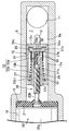
- FIG. 1 is a longitudinal side view of an intake air amount control apparatus for an engine according to a first embodiment of the present invention.
- FIG. 2 is an enlarged sectional view taken along line 2-2 of FIG.
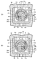
- First embodiment 3 is a cross-sectional view taken along the line 3-3 in FIG. 1.
- FIG. 3A shows a state during forward rotation of the electric motor
- FIG. 3B shows a state during reverse rotation.
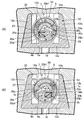
- FIG. 4 is a view corresponding to FIG. 3 showing a second embodiment of the present invention.
- Control body 7 ... Valve guide hole 8 a... Control inside surface 8 b... Control outside surface 10.
- Control wall 12c Front end wall 20 ⁇ Electric motor 20b ⁇ ⁇ ⁇ Output shaft 25 ⁇ ⁇ ⁇ Screw mechanism 26 ⁇ ⁇ ⁇ Anti-rotation means 27 ⁇ ⁇ ⁇ Slide piece 28 ⁇ ⁇ ⁇ Screw Hole 29 ... Screw shaft 31 ... First spring seat 32 ... Second spring seat 33 ... Coil spring 35 ... Pressing protrusion 35a ... First pressurizing part 35a1 ⁇ Pressure surface 35b ⁇ Second pressure portion 35b1 ⁇ ⁇ Pressure surface 36 ⁇ Pressure receiving protrusion 36a ⁇ ⁇ ⁇ First pressure receiving portion 36b ⁇ ⁇ ⁇ 2 pressure receiving portion
- reference numeral 1 denotes a throttle body attached to an engine for a motorcycle, for example, which has an intake passage 2 that communicates with an intake port of the engine at the center and is a butterfly type that opens and closes the intake passage 2.
- a throttle valve 3 is pivotally supported on the throttle body 1.
- a support base 4 is integrally formed on the upper side wall of the throttle body 1, and a control base 5 is superimposed on the support base 4 and fastened by a bolt (not shown).
- a bottomed cylindrical valve guide hole 7 is formed in the control base 5, and the valve guide hole 7 has a polygonal cross section (see FIG. 3, square in the illustrated example).
- the lower inner surface of the valve guide hole 7 along the direction of gravity is a control inner surface 8a.
- the control base 5 is provided with a measuring hole 10 that opens to the control inner side surface 8 a and an inlet hole 11 that opens to the control inner side surface 8 a on the bottom side of the valve guide hole 7 from the measuring hole 10.
- the measuring hole 10 has a long hole shape whose long diameter is arranged along the axial direction of the valve guide hole 7, and a control valve 12 for opening and closing the measuring hole 10 is slidably fitted in the valve guide hole 7. Is done.
- a bypass upstream passage 14 connecting the intake passage 2 upstream from the throttle valve 3 to the inlet hole 11 and the metering hole 10 are connected to the intake passage 2 downstream from the throttle valve 3.
- a bypass downstream passage 15 is provided.
- seal members 16 surrounding the connecting portion between the bypass upstream passage 14 and the inlet hole 11 and the connecting portion between the bypass downstream passage 15 and the measuring hole 10, respectively. Be dressed.
- the bypass upstream passage 14, the inlet hole 11, the valve guide hole 7, the metering hole 10 and the bypass downstream passage 15 constitute a bypass 17 that bypasses the throttle valve 3 and is connected to the intake passage 2.
- the control valve 12 is erected from a control wall 12a slidably contacting the control inner side surface 8a of the valve guide hole 7 with the lower side surface as a control outer side surface 8b, and the valve guide hole 7 A pair of side walls 12b, 12b facing both the left and right inner side surfaces, and a front end wall 12c that stands up from the front end of the control wall 12a on the bottom side of the valve guide hole 7 and connects the front end portions of the side walls 12b, 12b.
- control valve 12 is slidable in the axial direction in the valve guide hole 7 having a square cross section, but cannot rotate.
- the control base 5 is provided with a motor mounting hole 19 having a diameter larger than that of the valve guide hole 7, which is connected to the opening end of the valve guide hole 7 via a step portion 18, and a stator 20 a of the electric motor 20 is mounted on the control base 5. .
- a seal member 21 that is in close contact with the outer peripheral surface of the output shaft 20 b of the electric motor 20 is sandwiched between the front end surface of the stator 20 a and the step portion 18.
- the output shaft 20b of the electric motor 20 can be rotated forward and backward, and the control valve 12 is connected to the output shaft 20b via a screw mechanism 25.
- the screw mechanism 25 is connected to the control valve 12 via a detent means 26 and is connected to the slide piece 27 that synchronously opens and closes the control valve 12 and the output shaft 20 b of the electric motor 20.
- the screw shaft 29 is screwed into a screw hole 28 provided along the sliding direction of the control valve 12.
- the screw hole 28 is formed in a bag shape having a dead end portion 28a.
- the slide piece 27 is formed on the outer periphery of a cylindrical shaft 27a that passes through the U-shaped inward flange 12d of the control valve 12 and is disposed in the control valve 12, and a closed end wall 27b at the front end of the cylindrical shaft 27a.
- the cylindrical shaft 27a is provided with a bag-like screw hole 28 into which the screw shaft 29 is screwed.
- the cylindrical shaft 27a has a pair of coaxial holes 30 in the vicinity of the dead end portion 28a of the screw hole 28 so that the screw hole 28 is opened to both opposing surfaces on the outer periphery of the cylindrical shaft 27a and parallel to the open surface 12e of the control valve 12. 30 is provided.
- a first spring seat 31 is formed on the inner surface of the outward flange 27c, and a second spring seat 32 is formed on the inner surface of the inward flange 12d.
- the coil spring 33 is compressed between the spring seats 31 and 32, respectively. Due to the set load of the coil spring 33, the control valve 12 is urged backward, that is, toward the electric motor 20 with respect to the slide piece 27, so that the front end wall 12c of the slide piece 27 contacts the outward flange 27c. It is kept in contact. Thereby, the slide piece 27 and the control valve 12 are connected to each other without backlash in the axial direction.
- the coil spring 33 is integrally connected to the tightly wound portion 33a that is fitted to the outer peripheral portion of the cylindrical shaft 27a in which the lateral holes 30 and 30 are bored while being supported by the first spring seat 31. And a cone spring portion 33b having a larger diameter than the tightly wound portion 33a and having a large diameter end portion 33b1 supported by the control valve 12.
- the tightly wound portion 33a is an outer end of the lateral holes 30 and 30. The opening is closed.
- the anti-rotation means 26 includes a pressure protrusion 35 that integrally projects from the outer end surface of the closed end wall 27 b with the flange 27 c of the slide piece 27, and the control valve 12.
- a pressure receiving projection 36 is provided on the inner surface of the front end wall 12c so as to stand up from the inner surface of the wall 12a.
- the pressure protrusion 35 includes first and second pressure portions 35a having a pair of pressure surfaces 35a1 and 35b1 arranged in a V shape so as to sandwich the pressure receiving protrusion 36 along the rotation direction of the screw shaft 29. 35b is provided, and the opening angle ⁇ between the pair of pressure surfaces 35a1 and 35b1 arranged in the V shape is set to 90 ° or more. If it carries out like this, the pressurization surface 35a1, 35b1 of the 1st and 2nd pressurization part 35a, 35b which mutually opposes can be processed easily with an end mill.
- the pressure receiving protrusion 36 is provided with convex first and second pressure receiving portions 36a, 36b facing the pressure surfaces 35a1, 35b1, respectively.
- an electronic control unit (not shown) starts up the engine based on information on the engine operating conditions such as throttle valve opening, engine intake negative pressure, intake air temperature, engine temperature, and engine speed.
- the power supply to the electric motor 20 is controlled and the output shaft 20b of the electric motor 20 is controlled. Is rotated forward or reverse.
- the output shaft 20b rotates or reversely rotates, the rotation is transmitted to the control valve 12 via the slide piece 27 while being decelerated by the screw mechanism.
- the opening area to the valve guide hole 7 can be finely adjusted.
- the intake air amount of the engine flowing through the bypass 17 is finely controlled, and it is possible to cope with engine start, fast idling, normal idling, engine braking, and the like.
- the pressurizing surface 35a1 of the first pressurizing portion 35a presses the first pressure receiving portion 36a obliquely against the control inner surface 8a of the valve guide hole 7. Accordingly, the pressing force F applied to the first pressure receiving portion 36a is decomposed into a first component force perpendicular to the control inner surface 8a and a second component force F2 parallel to the control inner surface 8a, and the first component force F1.
- the control valve 12 is pressed against the control inner surface 8a, and the second component force F2 presses the control valve 12 against one inner surface of the valve guide hole 7.
- the reverse rotation torque T2 of the output shaft 20b is transmitted to the slide piece 27 via the friction between the screw shaft 29 and the screw hole 28.
- the pressurizing surface 35b1 of the second pressurizing portion 35b presses the second pressure receiving portion 36b against the control inner side surface 8a of the valve guide hole 7 in an oblique direction opposite to the previous time.
- the pressing force F applied to the second pressure receiving portion 36b is divided into a first component force perpendicular to the control inner surface 8a and a second component force F2 parallel to the control inner surface 8a, and the first component force F1 is controlled.
- the valve 12 is pressed against the control inner surface 8a, and the second component force F2 presses the control valve 12 against the other inner surface of the valve guide hole 7.
- the control valve 12 since the control valve 12 is pressed against the control inner surface 8a side of the valve guide hole 7 by the first component force F1 in both the forward rotation and the reverse rotation of the output shaft 20b, the control outer surface 8b. Can be brought into close contact with the control inner surface 8 a of the valve guide hole 7. That is, a gap can be eliminated from between the control inner side surface 8a and the control outer side surface 8b, and in this state, the control valve 12 opens and closes the measuring hole 10 opened to the control inner side surface 8a. 7 and the control valve 12 can eliminate the leakage of intake air, and therefore, even when the control valve 12 is fully closed or partially opened, an appropriate bypass intake air amount corresponding to the opening is supplied to the engine. be able to.
- the measuring hole 10 opened and closed by the control valve 12 has a long hole shape in which the long diameter is directed in the sliding direction of the control valve 12, so that the effective opening area is finely adjusted according to the sliding of the control valve 12. Can be adjusted.
- control valve 12 is simultaneously subjected to a pressing force toward the control inner surface 8a due to gravity and a suction force due to the intake negative pressure of the engine acting on the control outer surface 8b of the control valve 12 from the measuring hole 10, By these, the adhesion force between the control outer side surface 8b and the control inner side surface 8a is further strengthened.
- the screw shaft 29 of the screw mechanism 25 pulls the slide piece 27 rearward, and the tip end portion of the screw mechanism 29 abuts against the dead end portion 28a of the screw hole 28 of the slide piece 27, so that the control valve 12 is fully opened in synchronization with the slide piece 27. Is regulated, and the measuring hole 10 is fully opened.
- This fully open position becomes the reference position of the control valve 12, the closing position of the control valve 12 is determined by the rotation angle of the output shaft 20b of the electric motor 20 from this reference position, and the opening degree of the measuring hole 10 is controlled.
- the slide piece 27 and the control valve 12 are connected in the axial direction without any play by the coil spring 33, and the control valve 12 can follow the axial movement of the slide piece 27 without delay.
- the rotation preventing means 26 for connecting the slide piece 27 and the control valve 12 includes a pressure protrusion 35 that is integrally projected on the outer end surface of the closed end wall 27 b with the flange 27 c of the slide piece 27, and the control valve 12.
- the pressure receiving projection 36 is provided on the inner surface of the front end wall 12c so as to stand up from the inner surface of the control wall 12a. This can contribute to simplification of the structure.
- the rotation prevention means 26 can be configured compactly between the front end wall 12c of the control valve 12 and the outer end surface of the closed end wall 27b of the slide piece 27 accommodated in the control valve 12. An increase in the size of the quantity control device can be avoided.
- the screw hole 28 into which the screw shaft 29 is screwed is machined into the slide piece 27, first, the pilot hole of the screw hole 28 is first formed, and then a pair of coaxial holes 30 so as to cross the lower hole. , 30 is drilled, and then the screw hole is reamed into the lower hole.
- the horizontal holes 30 and 30 cut the burrs (working residue) due to processing, and the screw hole 28 is insufficiently processed. Not only can be surely prevented, but also the chips generated at that time can be smoothly discharged from the horizontal holes 30 and 30, and when the screw hole 28 is washed, the remaining chips are removed by a pair of coaxial Since it can discharge
- the dead end portion 28a can be constituted by the bottom portion of the lower hole of the screw hole 28, and the structure can be simplified.
- the horizontal holes 30 and 30 are formed larger in diameter than the lower hole, the cutting effect and discharging effect of the burr can be enhanced.
- a coil spring 33 arranged so as to surround the cylindrical shaft 27a of the slide piece 27 so as to connect the slide piece 27 and the control valve 12 in the axial direction is closed by the slide piece 27 so as to close the lateral holes 30 and 30.
- the tightly wound portion 33a whose end is supported by the first spring seat 31 of the slide piece 27 while being fitted to the outer peripheral surface of the slide piece 27, and the second spring seat 32 of the control valve 12 having a larger diameter than the tightly wound portion 33a. Since the cone spring portion 33b having the large-diameter end portion 33b1 to be supported is configured, the large-diameter end portion 33b1 of the coil spring 33 stabilizes the posture of the coil spring 33 in the control valve 12, and the tightly wound portion.
- the fully open position as the reference position of the control valve is regulated, so that the screw shaft 29 is applied to the dead end portion 28a of the screw hole 28.
- the slide piece 27 fitted with the coil spring 33 is housed in the control valve 12 from its open surface 12e while the coil spring 33 is contracted, and the pressure protrusion of the slide piece 27 is accommodated. 35 is engaged with the pressure receiving projection 36 of the control valve 12, and at the same time, the coil spring 33 is released and the cone spring portion 33 b is supported on the second spring seat 32 of the control valve 12.
- the screw shaft 29 on the electric motor 20 side is screwed into the screw hole 28 of the slide piece 27 to constitute an assembly of the electric motor 20 and the control valve 12.
- the screw shaft 29 may be first screwed into the screw hole 28 of the slide piece 27, and then the slide piece 27 may be housed in the control valve 12 together with the coil spring 33 from the open surface 12e.
- the slide piece 27 and the coil spring 33 can be easily assembled into the control valve 12 by using the open surface 12e of the control valve 12.
- the control valve 12 is fitted into the valve guide hole 7 of the control base 5.
- the open surface 12e of the control valve 12 is closed at the upper surface of the valve guide hole 7, the detachment of the slide piece 27 from the open surface 12e of the control valve 12 can be prevented.
- No special detachment prevention means is required, so that the assembly can be improved and the structure can be simplified.
- the accommodating space in the box-shaped control valve 12 whose upper surface is the open surface 12e has a wide cross section by the amount that the upper surface is the open surface 12e. Therefore, the control valve 12 can be made compact.
- the coil spring 33 and the slide piece 27 can be easily accommodated in the accommodation space.
- control valve 12 and the valve guide hole 7 have a polygonal cross section, the control valve 12 is prevented from rotating without using a special detent means such as a key and a key groove, and the screw mechanism 25 is stabilized. Actuation can be obtained.
- FIG. 4 Next, a second embodiment of the present invention shown in FIG. 4 will be described.
- valve guide hole 7 and the control valve 12 are formed so that the cross-section is an isosceles trapezoid, and the control inner side surface 8a and the control outer side surface 8b are arranged on the lower bottom of each. Except for this, the configuration is the same as that of the previous embodiment, and in FIG. 4, the same reference numerals are given to portions corresponding to those of the previous embodiment, and redundant description is omitted.
- any one of the first and second pressure members 35a and 35b is pressed against the corresponding first pressure member 36a or second pressure member 36b.
- the second component force F2 parallel to the control inner surface 8a generated in the first pressure receiving portion 36a or the second pressure receiving portion 36b causes the control valve 12 to move to either the left or right inner surface of the valve guide hole 7.
- the reaction force toward the control inner surface 8a is generated on the control valve 12 when receiving the second component force F2.
- the control outer surface 8b of the control valve 12 is more closely attached to the control inner surface 8a, and the effect of eliminating the gap between the control inner surface 8a and the control outer surface 8b can be enhanced. .
- the present invention is not limited to the above embodiment, and various design changes can be made without departing from the scope of the invention.
- a step motor or other types of motors can be used instead of the electric motor 20, a step motor or other types of motors.
- the reference position of the control valve 12 when the tip of the screw shaft 29 hits the dead end portion 28a of the screw hole 28 can be set to the fully closed position of the control valve 12.
- the entire cone spring portion 33b of the coil spring 33 can be formed in a cylindrical shape having the same diameter as the large-diameter end portion 33b1.
Landscapes
- Engineering & Computer Science (AREA)
- Chemical & Material Sciences (AREA)
- Combustion & Propulsion (AREA)
- Mechanical Engineering (AREA)
- General Engineering & Computer Science (AREA)
- Control Of Throttle Valves Provided In The Intake System Or In The Exhaust System (AREA)
- Electrically Driven Valve-Operating Means (AREA)
Abstract
Description
7・・・・・バルブガイド孔
8a・・・・制御内側面
8b・・・・制御外側面
10・・・・計量孔
12・・・・制御バルブ
12a・・・制御壁
12c・・・前端壁
20・・・・電動モータ
20b・・・出力軸
25・・・・ねじ機構
26・・・・回り止め手段
27・・・・スライドピース
28・・・・ねじ孔
29・・・・ねじ軸
31・・・・第1スプリング座
32・・・・第2スプリング座
33・・・・コイルスプリング
35・・・・加圧突起
35a・・・第1加圧部
35a1・・加圧面
35b・・・第2加圧部
35b1・・加圧面
36・・・・受圧突起
36a・・・第1受圧部
36b・・・第2受圧部
Claims (5)
- 制御基体(5)に,バルブガイド孔(7)と,このバルブガイド孔(7)の内側面に開口し,前記バルブガイド孔(7)を通してエンジンの吸気が通過する計量孔(10)とを形成し,前記バルブガイド孔(7)には,前記計量孔(10)を開閉する制御バルブ(12)を摺動自在且つ回転不能に嵌装し,この制御バルブ(12)に,これを開閉駆動すべく,前記制御基体(5)に取り付けられる電動モータ(20)の正逆転可能の出力軸(20b)をねじ機構(25)を介して連結してなり,前記ねじ機構(25)が,前記制御バルブ(12)に回り止め手段(26)を介し連結されて該制御バルブ(12)を同期的に開閉駆動するスライドピース(27)と,前記出力軸(20b)に連設され,前記スライドピース(27)に前記制御バルブ(12)の摺動方向に沿って設けられたねじ孔(28)に螺合するねじ軸(29)とで構成される,エンジンの吸気量制御装置において,
前記バルブガイド孔(7)の内側面に制御内側面(8a)を形成すると共に,この制御内側面(8a)に前記計量孔(10)を開口する一方,前記制御バルブ(12)の外側面に,前記制御内側面(8a)と摺接する制御外側面(8b)を形成し,
前記回り止め手段(26)を,前記ねじ軸(29)の回転方向に沿って並ぶよう前記スライドピース(27)に設けられる第1及び第2加圧部(35a,35b)と,前記ねじ軸(29)の回転方向で前記第1及び第2加圧部(35a,35b)にそれぞれ対向するよう前記制御バルブ(12)に設けられる第1及び第2受圧部(36a,36b)とで構成し,
前記第1加圧部(35a)は,前記ねじ軸(29)の正転時,第1受圧部(36a)を押圧することにより,前記制御外側面(8b)を前記制御内側面(8a)に密接させるように前記スライドピース(27)を押圧し,
また前記第2加圧部(35b)は,前記ねじ軸(29)の逆転時,第2受圧部(36b)を押圧することにより,前記制御外側面(8b)を前記制御内側面(8a)に密接させるように前記スライドピース(27)を押圧することを特徴とする,エンジンの吸気量制御装置。 - 請求項1記載のエンジンの吸気量制御装置において,
前記第1及び第2加圧部(35a,35b)を前記スライドピース(27)に一体に形成し,前記第1及び第2受圧部(36a,36b)を前記制御バルブ(12)に一体に形成したことを特徴とする,エンジンの吸気量制御装置。 - 請求項2記載のエンジンの吸気量制御装置において,
前記制御バルブ(12)には,外側面を前記制御外側面(8b)とする制御壁(12a)と,この制御壁(12a)の,前記電動モータ(20)と反対側の前端部から起立する前端壁(12c)とを設ける一方,前記スライドピース(27)を,その前端面が前記前端壁(12c)に対向するように前記制御バルブ(12)内に配置し,前記制御壁(12a)の内面側から起立して前記第1及び第2受圧部(36a,36b)を有する共通の受圧突起(36)を前記前端壁(12c)の内面に一体に形成し,前記第1及び第2加圧部(35a,35b)を,これらの間に前記受圧突起(36)を挟むようにV字状に配置しながら前記スライドピース(27)の前端面に一体に形成し,前記第1加圧部(35a)が前記第1受圧部(36a)を押圧するときも,前記第2加圧部(35b)が前記第2受圧部(36b)を押圧するときも,前記受圧突起(36)に作用する分力(F1)が,前記制御外側面(8b)を前記制御内側面(8a)に密接させるように前記スライドピース(27)を押圧することを特徴とする,エンジンの吸気量制御装置。 - 請求項3記載のエンジンの吸気量制御装置において,
前記第1及び第2加圧部(35a,35b)のV字状に配置される加圧面(35a1,35b1)の開き角度(θ)を90°以上に設定したことを特徴とする,エンジンの吸気量制御装置。 - 請求項3又は4記載のエンジンの吸気量制御装置において,
前記スライドピース(27)の前端部に第1スプリング座(31)を設け,この第1スプリング座(31)と対向する第2スプリング座(32)を前記制御バルブ(12)の後端部に設け,これら第1及び第2スプリング座(31,32)間に,前記スライドピース(27)に対して前記制御バルブ(12)を後方へ付勢して前記第1及び第2加圧部(35a,35b)と前記第1及び第2受圧部(36a,36b)との対向位置を保持するコイルスプリング(33)を縮設したことを特徴とする,エンジンの吸気量制御装置。
Priority Applications (1)
| Application Number | Priority Date | Filing Date | Title |
|---|---|---|---|
| BR112015006677-1A BR112015006677B1 (pt) | 2012-09-28 | 2013-09-25 | Dispositivo de controle da admissão de ar do motor |
Applications Claiming Priority (2)
| Application Number | Priority Date | Filing Date | Title |
|---|---|---|---|
| JP2012217544A JP5950203B2 (ja) | 2012-09-28 | 2012-09-28 | エンジンの吸気量制御装置 |
| JP2012-217544 | 2012-09-28 |
Publications (1)
| Publication Number | Publication Date |
|---|---|
| WO2014050858A1 true WO2014050858A1 (ja) | 2014-04-03 |
Family
ID=50388255
Family Applications (1)
| Application Number | Title | Priority Date | Filing Date |
|---|---|---|---|
| PCT/JP2013/075847 Ceased WO2014050858A1 (ja) | 2012-09-28 | 2013-09-25 | エンジンの吸気量制御装置 |
Country Status (4)
| Country | Link |
|---|---|
| JP (1) | JP5950203B2 (ja) |
| CN (1) | CN103711593B (ja) |
| BR (1) | BR112015006677B1 (ja) |
| WO (1) | WO2014050858A1 (ja) |
Citations (5)
| Publication number | Priority date | Publication date | Assignee | Title |
|---|---|---|---|---|
| US20020100822A1 (en) * | 2001-01-26 | 2002-08-01 | Oliver Jack David | Needle/armature rotation limiting feature |
| JP2004183523A (ja) * | 2002-12-02 | 2004-07-02 | Keihin Corp | エンジンのアイドル吸気量制御装置 |
| JP2005113718A (ja) * | 2003-10-03 | 2005-04-28 | Keihin Corp | バイパス吸気量制御装置 |
| JP2009114997A (ja) * | 2007-11-07 | 2009-05-28 | Keihin Corp | バイパス吸気量制御装置 |
| JP2010163890A (ja) * | 2009-01-13 | 2010-07-29 | Keihin Corp | バイパス吸気量制御装置 |
Family Cites Families (5)
| Publication number | Priority date | Publication date | Assignee | Title |
|---|---|---|---|---|
| JP3935075B2 (ja) * | 2000-11-30 | 2007-06-20 | 株式会社ケーヒン | エンジンの吸気装置 |
| JP4234121B2 (ja) * | 2005-09-02 | 2009-03-04 | 株式会社ケーヒン | エンジン用吸気装置 |
| JP4459154B2 (ja) * | 2005-11-09 | 2010-04-28 | 株式会社ケーヒン | 多連スロットルボデーにおけるエアバイパス装置 |
| JP2007332904A (ja) * | 2006-06-16 | 2007-12-27 | Mikuni Corp | 弁装置及びアイドル空気量制御装置 |
| JP4690990B2 (ja) * | 2006-10-04 | 2011-06-01 | 株式会社ケーヒン | 燃料噴射装置におけるエアバイパス装置 |
-
2012
- 2012-09-28 JP JP2012217544A patent/JP5950203B2/ja active Active
-
2013
- 2013-09-25 WO PCT/JP2013/075847 patent/WO2014050858A1/ja not_active Ceased
- 2013-09-25 BR BR112015006677-1A patent/BR112015006677B1/pt active IP Right Grant
- 2013-09-27 CN CN201310452566.3A patent/CN103711593B/zh active Active
Patent Citations (5)
| Publication number | Priority date | Publication date | Assignee | Title |
|---|---|---|---|---|
| US20020100822A1 (en) * | 2001-01-26 | 2002-08-01 | Oliver Jack David | Needle/armature rotation limiting feature |
| JP2004183523A (ja) * | 2002-12-02 | 2004-07-02 | Keihin Corp | エンジンのアイドル吸気量制御装置 |
| JP2005113718A (ja) * | 2003-10-03 | 2005-04-28 | Keihin Corp | バイパス吸気量制御装置 |
| JP2009114997A (ja) * | 2007-11-07 | 2009-05-28 | Keihin Corp | バイパス吸気量制御装置 |
| JP2010163890A (ja) * | 2009-01-13 | 2010-07-29 | Keihin Corp | バイパス吸気量制御装置 |
Also Published As
| Publication number | Publication date |
|---|---|
| JP5950203B2 (ja) | 2016-07-13 |
| CN103711593A (zh) | 2014-04-09 |
| JP2014070576A (ja) | 2014-04-21 |
| BR112015006677A2 (pt) | 2017-07-04 |
| CN103711593B (zh) | 2017-10-24 |
| BR112015006677B1 (pt) | 2022-12-06 |
Similar Documents
| Publication | Publication Date | Title |
|---|---|---|
| US7694662B2 (en) | Bypass-intake-flow control apparatus | |
| JP5602723B2 (ja) | ステアリングホイールと重ね合わせギアを有する自動車用ステアリング装置 | |
| JP6719653B2 (ja) | 動力伝達装置 | |
| US8291885B2 (en) | Valve having a sleeve to prevent contamination and condensation | |
| FR3103237A1 (fr) | Moyeu d’alimentation d’huile assemblé et triple embrayage humide comprenant ce moyeu d’alimentation d’huile assemblé | |
| EP3366938A1 (fr) | Dispositif de rappel elastique pour mecanisme d'embrayage humide et embrayage humide comprenant un tel dispositif de rappel elastique | |
| JP5950203B2 (ja) | エンジンの吸気量制御装置 | |
| JP5297623B2 (ja) | エンジン用アクティブ吸気システム | |
| JP5963201B2 (ja) | エンジンの吸気量制御装置 | |
| JP5727620B2 (ja) | エンジンの吸気制御装置 | |
| JP2014070576A5 (ja) | ||
| EP2314488A1 (fr) | Installation de freins a maître-cylindre | |
| JP6029208B2 (ja) | エンジンの吸気量制御装置 | |
| JP2016114123A (ja) | 軸継手、ダンパ装置および衝撃トルク低減装置並びに部品締結機 | |
| JP4307274B2 (ja) | 軸連結部構造 | |
| FR2921593A3 (fr) | Agencement pour la fixation d'un troncon d'une ligne d'echappement de vehicule automobile | |
| JP2013087733A (ja) | エンジンの吸気制御装置 | |
| JP3245335B2 (ja) | ドアクローザ | |
| JP5963203B2 (ja) | スロットルボディのバイパス制御装置 | |
| JPH11264481A (ja) | パイロットチェック弁及び回転シリンダ構造 | |
| JP7608231B2 (ja) | スロットル装置の製造方法 | |
| JP4815252B2 (ja) | 定車速制御装置 | |
| FR2974039A1 (fr) | Groupe motopropulseur comportant un palier relais integre | |
| JP5693742B2 (ja) | エンジンの吸気制御装置 | |
| JP5315141B2 (ja) | 多連スロットルボディにおけるスロットル弁の同調装置 |
Legal Events
| Date | Code | Title | Description |
|---|---|---|---|
| 121 | Ep: the epo has been informed by wipo that ep was designated in this application |
Ref document number: 13841048 Country of ref document: EP Kind code of ref document: A1 |
|
| NENP | Non-entry into the national phase |
Ref country code: DE |
|
| REG | Reference to national code |
Ref country code: BR Ref legal event code: B01A Ref document number: 112015006677 Country of ref document: BR |
|
| WWE | Wipo information: entry into national phase |
Ref document number: IDP00201502322 Country of ref document: ID |
|
| 122 | Ep: pct application non-entry in european phase |
Ref document number: 13841048 Country of ref document: EP Kind code of ref document: A1 |
|
| ENP | Entry into the national phase |
Ref document number: 112015006677 Country of ref document: BR Kind code of ref document: A2 Effective date: 20150325 |