WO2014049949A1 - セパレータ一体形電極及び非水電解質二次電池 - Google Patents
セパレータ一体形電極及び非水電解質二次電池 Download PDFInfo
- Publication number
- WO2014049949A1 WO2014049949A1 PCT/JP2013/005014 JP2013005014W WO2014049949A1 WO 2014049949 A1 WO2014049949 A1 WO 2014049949A1 JP 2013005014 W JP2013005014 W JP 2013005014W WO 2014049949 A1 WO2014049949 A1 WO 2014049949A1
- Authority
- WO
- WIPO (PCT)
- Prior art keywords
- porous layer
- separator
- electrode
- electrolyte secondary
- layer
- Prior art date
- Legal status (The legal status is an assumption and is not a legal conclusion. Google has not performed a legal analysis and makes no representation as to the accuracy of the status listed.)
- Ceased
Links
Images

Classifications
-
- D—TEXTILES; PAPER
- D04—BRAIDING; LACE-MAKING; KNITTING; TRIMMINGS; NON-WOVEN FABRICS
- D04H—MAKING TEXTILE FABRICS, e.g. FROM FIBRES OR FILAMENTARY MATERIAL; FABRICS MADE BY SUCH PROCESSES OR APPARATUS, e.g. FELTS, NON-WOVEN FABRICS; COTTON-WOOL; WADDING ; NON-WOVEN FABRICS FROM STAPLE FIBRES, FILAMENTS OR YARNS, BONDED WITH AT LEAST ONE WEB-LIKE MATERIAL DURING THEIR CONSOLIDATION
- D04H1/00—Non-woven fabrics formed wholly or mainly of staple fibres or like relatively short fibres
- D04H1/40—Non-woven fabrics formed wholly or mainly of staple fibres or like relatively short fibres from fleeces or layers composed of fibres without existing or potential cohesive properties
- D04H1/413—Non-woven fabrics formed wholly or mainly of staple fibres or like relatively short fibres from fleeces or layers composed of fibres without existing or potential cohesive properties containing granules other than absorbent substances
-
- H—ELECTRICITY
- H01—ELECTRIC ELEMENTS
- H01M—PROCESSES OR MEANS, e.g. BATTERIES, FOR THE DIRECT CONVERSION OF CHEMICAL ENERGY INTO ELECTRICAL ENERGY
- H01M50/00—Constructional details or processes of manufacture of the non-active parts of electrochemical cells other than fuel cells, e.g. hybrid cells
- H01M50/40—Separators; Membranes; Diaphragms; Spacing elements inside cells
- H01M50/46—Separators, membranes or diaphragms characterised by their combination with electrodes
-
- D—TEXTILES; PAPER
- D04—BRAIDING; LACE-MAKING; KNITTING; TRIMMINGS; NON-WOVEN FABRICS
- D04H—MAKING TEXTILE FABRICS, e.g. FROM FIBRES OR FILAMENTARY MATERIAL; FABRICS MADE BY SUCH PROCESSES OR APPARATUS, e.g. FELTS, NON-WOVEN FABRICS; COTTON-WOOL; WADDING ; NON-WOVEN FABRICS FROM STAPLE FIBRES, FILAMENTS OR YARNS, BONDED WITH AT LEAST ONE WEB-LIKE MATERIAL DURING THEIR CONSOLIDATION
- D04H1/00—Non-woven fabrics formed wholly or mainly of staple fibres or like relatively short fibres
- D04H1/70—Non-woven fabrics formed wholly or mainly of staple fibres or like relatively short fibres characterised by the method of forming fleeces or layers, e.g. reorientation of fibres
- D04H1/72—Non-woven fabrics formed wholly or mainly of staple fibres or like relatively short fibres characterised by the method of forming fleeces or layers, e.g. reorientation of fibres the fibres being randomly arranged
- D04H1/728—Non-woven fabrics formed wholly or mainly of staple fibres or like relatively short fibres characterised by the method of forming fleeces or layers, e.g. reorientation of fibres the fibres being randomly arranged by electro-spinning
-
- H—ELECTRICITY
- H01—ELECTRIC ELEMENTS
- H01M—PROCESSES OR MEANS, e.g. BATTERIES, FOR THE DIRECT CONVERSION OF CHEMICAL ENERGY INTO ELECTRICAL ENERGY
- H01M10/00—Secondary cells; Manufacture thereof
- H01M10/05—Accumulators with non-aqueous electrolyte
-
- H—ELECTRICITY
- H01—ELECTRIC ELEMENTS
- H01M—PROCESSES OR MEANS, e.g. BATTERIES, FOR THE DIRECT CONVERSION OF CHEMICAL ENERGY INTO ELECTRICAL ENERGY
- H01M10/00—Secondary cells; Manufacture thereof
- H01M10/05—Accumulators with non-aqueous electrolyte
- H01M10/052—Li-accumulators
-
- H—ELECTRICITY
- H01—ELECTRIC ELEMENTS
- H01M—PROCESSES OR MEANS, e.g. BATTERIES, FOR THE DIRECT CONVERSION OF CHEMICAL ENERGY INTO ELECTRICAL ENERGY
- H01M10/00—Secondary cells; Manufacture thereof
- H01M10/05—Accumulators with non-aqueous electrolyte
- H01M10/058—Construction or manufacture
- H01M10/0585—Construction or manufacture of accumulators having only flat construction elements, i.e. flat positive electrodes, flat negative electrodes and flat separators
-
- H—ELECTRICITY
- H01—ELECTRIC ELEMENTS
- H01M—PROCESSES OR MEANS, e.g. BATTERIES, FOR THE DIRECT CONVERSION OF CHEMICAL ENERGY INTO ELECTRICAL ENERGY
- H01M50/00—Constructional details or processes of manufacture of the non-active parts of electrochemical cells other than fuel cells, e.g. hybrid cells
- H01M50/40—Separators; Membranes; Diaphragms; Spacing elements inside cells
- H01M50/409—Separators, membranes or diaphragms characterised by the material
- H01M50/411—Organic material
- H01M50/414—Synthetic resins, e.g. thermoplastics or thermosetting resins
-
- H—ELECTRICITY
- H01—ELECTRIC ELEMENTS
- H01M—PROCESSES OR MEANS, e.g. BATTERIES, FOR THE DIRECT CONVERSION OF CHEMICAL ENERGY INTO ELECTRICAL ENERGY
- H01M50/00—Constructional details or processes of manufacture of the non-active parts of electrochemical cells other than fuel cells, e.g. hybrid cells
- H01M50/40—Separators; Membranes; Diaphragms; Spacing elements inside cells
- H01M50/409—Separators, membranes or diaphragms characterised by the material
- H01M50/411—Organic material
- H01M50/429—Natural polymers
- H01M50/4295—Natural cotton, cellulose or wood
-
- H—ELECTRICITY
- H01—ELECTRIC ELEMENTS
- H01M—PROCESSES OR MEANS, e.g. BATTERIES, FOR THE DIRECT CONVERSION OF CHEMICAL ENERGY INTO ELECTRICAL ENERGY
- H01M50/00—Constructional details or processes of manufacture of the non-active parts of electrochemical cells other than fuel cells, e.g. hybrid cells
- H01M50/40—Separators; Membranes; Diaphragms; Spacing elements inside cells
- H01M50/409—Separators, membranes or diaphragms characterised by the material
- H01M50/431—Inorganic material
- H01M50/434—Ceramics
-
- H—ELECTRICITY
- H01—ELECTRIC ELEMENTS
- H01M—PROCESSES OR MEANS, e.g. BATTERIES, FOR THE DIRECT CONVERSION OF CHEMICAL ENERGY INTO ELECTRICAL ENERGY
- H01M50/00—Constructional details or processes of manufacture of the non-active parts of electrochemical cells other than fuel cells, e.g. hybrid cells
- H01M50/40—Separators; Membranes; Diaphragms; Spacing elements inside cells
- H01M50/409—Separators, membranes or diaphragms characterised by the material
- H01M50/44—Fibrous material
-
- H—ELECTRICITY
- H01—ELECTRIC ELEMENTS
- H01M—PROCESSES OR MEANS, e.g. BATTERIES, FOR THE DIRECT CONVERSION OF CHEMICAL ENERGY INTO ELECTRICAL ENERGY
- H01M50/00—Constructional details or processes of manufacture of the non-active parts of electrochemical cells other than fuel cells, e.g. hybrid cells
- H01M50/40—Separators; Membranes; Diaphragms; Spacing elements inside cells
- H01M50/409—Separators, membranes or diaphragms characterised by the material
- H01M50/449—Separators, membranes or diaphragms characterised by the material having a layered structure
- H01M50/451—Separators, membranes or diaphragms characterised by the material having a layered structure comprising layers of only organic material and layers containing inorganic material
-
- H—ELECTRICITY
- H01—ELECTRIC ELEMENTS
- H01M—PROCESSES OR MEANS, e.g. BATTERIES, FOR THE DIRECT CONVERSION OF CHEMICAL ENERGY INTO ELECTRICAL ENERGY
- H01M50/00—Constructional details or processes of manufacture of the non-active parts of electrochemical cells other than fuel cells, e.g. hybrid cells
- H01M50/40—Separators; Membranes; Diaphragms; Spacing elements inside cells
- H01M50/409—Separators, membranes or diaphragms characterised by the material
- H01M50/449—Separators, membranes or diaphragms characterised by the material having a layered structure
- H01M50/454—Separators, membranes or diaphragms characterised by the material having a layered structure comprising a non-fibrous layer and a fibrous layer superimposed on one another
-
- H—ELECTRICITY
- H01—ELECTRIC ELEMENTS
- H01M—PROCESSES OR MEANS, e.g. BATTERIES, FOR THE DIRECT CONVERSION OF CHEMICAL ENERGY INTO ELECTRICAL ENERGY
- H01M10/00—Secondary cells; Manufacture thereof
- H01M10/05—Accumulators with non-aqueous electrolyte
- H01M10/056—Accumulators with non-aqueous electrolyte characterised by the materials used as electrolytes, e.g. mixed inorganic/organic electrolytes
- H01M10/0564—Accumulators with non-aqueous electrolyte characterised by the materials used as electrolytes, e.g. mixed inorganic/organic electrolytes the electrolyte being constituted of organic materials only
- H01M10/0566—Liquid materials
-
- Y—GENERAL TAGGING OF NEW TECHNOLOGICAL DEVELOPMENTS; GENERAL TAGGING OF CROSS-SECTIONAL TECHNOLOGIES SPANNING OVER SEVERAL SECTIONS OF THE IPC; TECHNICAL SUBJECTS COVERED BY FORMER USPC CROSS-REFERENCE ART COLLECTIONS [XRACs] AND DIGESTS
- Y02—TECHNOLOGIES OR APPLICATIONS FOR MITIGATION OR ADAPTATION AGAINST CLIMATE CHANGE
- Y02E—REDUCTION OF GREENHOUSE GAS [GHG] EMISSIONS, RELATED TO ENERGY GENERATION, TRANSMISSION OR DISTRIBUTION
- Y02E60/00—Enabling technologies; Technologies with a potential or indirect contribution to GHG emissions mitigation
- Y02E60/10—Energy storage using batteries
-
- Y—GENERAL TAGGING OF NEW TECHNOLOGICAL DEVELOPMENTS; GENERAL TAGGING OF CROSS-SECTIONAL TECHNOLOGIES SPANNING OVER SEVERAL SECTIONS OF THE IPC; TECHNICAL SUBJECTS COVERED BY FORMER USPC CROSS-REFERENCE ART COLLECTIONS [XRACs] AND DIGESTS
- Y02—TECHNOLOGIES OR APPLICATIONS FOR MITIGATION OR ADAPTATION AGAINST CLIMATE CHANGE
- Y02P—CLIMATE CHANGE MITIGATION TECHNOLOGIES IN THE PRODUCTION OR PROCESSING OF GOODS
- Y02P70/00—Climate change mitigation technologies in the production process for final industrial or consumer products
- Y02P70/50—Manufacturing or production processes characterised by the final manufactured product
Definitions
- the present invention relates to a separator-integrated electrode and a nonaqueous electrolyte secondary battery provided with the separator-integrated electrode.
- non-aqueous electrolyte secondary batteries represented by lithium (Li) ion batteries having a high energy density is increasing year by year, but at present, the demand is not fully met.
- non-aqueous electrolyte secondary batteries not only mobile applications such as mobile phones, portable computers, PDAs, and portable music players, but also electric tools, electric bicycles, electric vehicles (EV), Development is progressing for medium-sized to large-sized battery applications ranging from power for hybrid electric vehicles (HEV, PHEV) to power storage such as backup power supplies and power storage, and the applications are diversifying.
- HEV hybrid electric vehicles
- PHEV power storage
- backup power supplies and power storage and the applications are diversifying.
- the structure of the nonaqueous electrolyte secondary battery has also diversified according to the use of these nonaqueous electrolyte secondary batteries, and a cylindrical battery using a wound electrode body in which an electrode and a separator are wound in a spiral shape,
- non-aqueous electrolyte secondary batteries has become more complex due to the diversification of non-aqueous electrolyte secondary battery shapes. This has led to increased production costs and lead times for non-aqueous electrolyte secondary batteries. Sexual deterioration will occur. For this reason, in the manufacture of diversifying non-aqueous electrolyte secondary batteries, it is essential to develop a technology that simplifies the manufacturing process of non-aqueous electrolyte secondary batteries.
- Polyolefin microporous membranes used as separators for non-aqueous electrolyte secondary batteries increase the material cost of the battery, and the winding and lamination process with the electrodes complicates the manufacturing process and increases the lead time. Invite. For this reason, the present inventors have made various attempts to develop a separatorless battery without using a conventional polyolefin microporous membrane.
- an insulating porous material that transmits lithium ions is used as a separator between a positive electrode plate and a negative electrode plate.
- This separator is made of polyolefin, for example, made of polyethylene or polypropylene.
- a microporous membrane is used.
- Patent Document 1 a negative electrode formed by laminating a negative electrode active material coating layer on a current collector, a positive electrode formed by laminating a positive electrode active material coating layer on a current collector, a separator, and a non-aqueous electrolyte
- An invention of a nonaqueous electrolyte secondary battery in which a porous protective film containing solid fine particles is formed to have a thickness in the range of 0.1 to 200 ⁇ m is disclosed.
- Patent Document 2 an electrochemical device formed by a porous layer containing a fiber formed by an electrospinning method as a separator in a separator electrode integrated power storage device for an electrochemical device in which a separator is joined and integrated with an electrode surface.
- An invention of an element separator integrated power storage element is disclosed.
- Patent Document 1 a non-aqueous electrolyte in which an internal short circuit due to a falling active material is suppressed by a porous protective film formed on the surface of a negative electrode active material coating layer or a positive electrode active material coating layer.
- a secondary battery can be obtained.
- a porous layer containing fibers is formed on the surface of the active material mixture layer of the electrode, so that the porous layer is thinned without impairing mechanical strength.
- An electrochemical element separator-integrated energy storage device that can be layered and can reduce internal resistance can be obtained.
- An integrated electrode and a nonaqueous electrolyte secondary battery using the separator integrated electrode can be provided.
- the separator-integrated electrode of the present invention includes a current collector, an electrode mixture layer formed on the current collector, and a porous layer formed on the electrode mixture layer.
- the quality layer includes particles made of an inorganic material and fibers made of a resin material.
- the porous layer formed on the surface of the electrode mixture layer is formed of particles including inorganic material particles and resin material fibers, As a result, it becomes difficult to make the fine shape of the porous layer non-uniform as in the technology, and the generation of a low resistance portion against the permeation of lithium ions is suppressed. Thereby, according to the separator integrated electrode of this invention, precipitation of the dendritic lithium metal resulting from an increase in lithium ion concentration in a low resistance part is suppressed.
- the fiber made of a resin material forming the separator-integrated electrode of the present invention is preferably a fibrous resin material having a diameter of 1 to several hundred nm, but a fiber of about several ⁇ m can also be used.
- the separator-integrated electrode of the present invention is applied to the positive electrode in which the positive electrode active material mixture layer is formed on the surface of the positive electrode current collector and the negative electrode in which the negative electrode active material mixture layer is formed on the surface of the negative electrode current collector. However, the same can be applied.
- the porous layer includes a first porous layer including particles made of an inorganic material formed on the electrode mixture layer, and the first porous layer. And a second porous layer containing fibers made of a resin material formed thereon.
- a first porous layer containing inorganic material particles and a second porous layer formed of resin material fibers are formed on the surface of the electrode mixture layer. Therefore, the characteristics based on the difference in the forming material of each porous layer are favorably exhibited.
- the separator-integrated electrode when the average thickness of the second porous layer is x and the average thickness of the first porous layer is y, 0.5 ⁇ x / (x + y) ⁇ 0.95 It is preferable to do.
- X / (x + y) obtained by dividing the thickness x of the porous layer constituted by the fiber made of the resin material by the total thickness (x + y) of the porous layer containing the particles made of the inorganic material and the fiber made of the fiber. If the value of) is less than 0.5, the resistance distribution between the porous layer containing particles made of inorganic material and the porous layer formed of fibers becomes non-uniform, and an internal short circuit is likely to occur. When the value of x / (x + y) exceeds 0.95, the generation of the low resistance portion with respect to the permeation of lithium ions in the porous layer constituted by the fiber made of the resin material is further suppressed, but the internal resistance increases. Therefore, it is not preferable.
- the fiber made of a resin material forming the second porous layer is made of polypropylene, polyethylene, polystyrene, polyethylene oxide, polyethylene terephthalate, polybutylene terephthalate, polyethylene naphthalate, poly-m.
- the second porous layer produced using these resin-made fibers can be obtained with good electrical insulation and porosity, when a non-aqueous electrolyte secondary battery is formed, This makes it possible to obtain a non-aqueous electrolyte secondary battery in which lithium dendrite is less likely to occur and internal short circuit is less likely to occur.
- the inorganic material particles contained in the first porous layer are at least one selected from titania (excluding anatase structure), alumina, zirconia, and magnesia. Preferably there is.
- inorganic material particles have good electrical insulation, low cohesiveness, and good dispersibility in a solvent, so that a homogeneous first porous layer can be easily formed. Will be able to.
- the fiber of the resin material that forms the second porous layer is formed by an electrospinning method.
- the shape of the formed fiber can be easily controlled, the fiber length can be easily increased, and the resin material that can be used is less limited.
- the fiber can easily enter the pores of the insulating first porous layer by electrostatic force, the second porous layer can be formed more stably and the second porous layer can be formed. The adhesion strength between the layer and the first porous layer is increased.
- a non-aqueous electrolyte secondary battery of the present invention is a non-aqueous electrolyte secondary battery comprising any of the above-described separator integrated electrode and a counter electrode paired with the separator integrated electrode,
- the counter electrode has a counter electrode mixture layer formed on the surface of the current collector, and the counter electrode mixture layer is disposed so as to be in contact with the second porous layer of the separator-integrated electrode,
- the first porous layer and the second porous layer of the separator-integrated electrode are impregnated with a nonaqueous electrolytic solution.
- the nonaqueous electrolyte secondary battery may include a separate separator.
- the nonaqueous electrolyte secondary battery of the present invention the occurrence of a short circuit between the electrodes is suppressed, and a highly reliable nonaqueous electrolyte secondary battery is obtained.
- FIG. 1 is a schematic cross-sectional view of a nonaqueous electrolyte secondary battery according to an embodiment.
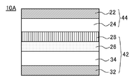
- FIG. 2 is a schematic cross-sectional view of a nonaqueous electrolyte secondary battery according to a modification.
- the positive electrode 12 is a separator-integrated electrode, and the positive electrode 12 and the negative electrode 14 that are the separator-integrated electrode are stacked.
- a positive electrode current collector 22 In the positive electrode 12, a positive electrode current collector 22, a positive electrode mixture layer 24, a first porous layer 26 including particles made of an inorganic material, and a second porous layer 28 including a resin material are laminated. It has a configuration.
- the negative electrode 14 has a configuration in which a negative electrode current collector 32 and a negative electrode mixture layer 34 are laminated.
- the positive electrode 12 includes a positive electrode current collector 22 made of aluminum or an aluminum alloy, a positive electrode mixture layer 24 formed on the surface of the positive electrode current collector 22, and a positive electrode current collector of the positive electrode mixture layer 24.
- the first porous layer 26 formed on the surface opposite to the electric body 22 and the second porous layer formed on the surface opposite to the positive electrode mixture layer 24 of the first porous layer 26.
- a quality layer 28 is also included.
- the first porous layer 26 is composed of, for example, particles made of an inorganic material and a resin material.
- particles made of an inorganic material titania (TiO 2 ), alumina (Al 2 O 3 ), zirconia (ZrO 2 ), magnesia (MgO), or the like can be used.
- the rutile-structure titania is less prone to the desorption / insertion of lithium ions, and is less likely to cause occlusion of lithium ions or expression of electronic conductivity due to the environmental atmosphere (potential).
- a titania is a rutile structure.
- these particles made of an inorganic material preferably have an average particle size of 1 ⁇ m or less, and are surface-treated with aluminum (Al), silicon (Si), titanium (Ti) or the like in consideration of the dispersibility of the slurry. Those are particularly preferred.
- a water-insoluble resin or a water-soluble resin can be used as the resin material constituting the first porous layer 26 .
- the water-insoluble resin polymethyl methacrylate, polyethylene terephthalate, polybutylene terephthalate, polyethylene naphthalate, polyvinylidene fluoride, polyacrylonitrile, polyimide, polyamide, polyamideimide, polytetrafluoroethylene and the like can be used.
- the water-soluble resin polyvinyl alcohol, polyvinyl pyrrolidone, polyacrylamide, polyvinyl methyl ether, polyethylene glycol, or the like can be used.
- the resin-based material constituting the first porous layer 26 is preferably dissolved in a solvent different from the solvent used for the positive electrode mixture slurry for forming the positive electrode mixture layer. Therefore, when the positive electrode active material mixture layer is formed from the positive electrode mixture slurry using N-methyl-2-pyrrolidone (NMP) as the solvent and the first porous layer 26 is formed on this surface, the first porous layer is formed.
- the solvent that dissolves the resin-based material constituting the porous layer 26 is preferably water.
- the inorganic material particles are dispersed, and the solvent for dissolving the resin material may be N, N-dimethylacetamide (DMAc), N- Examples thereof include methyl-2-pyrrolidone (NMP), phosphoric acid hexamethyltriamide (HMPA), N, N-dimethylformamide (DMF), dimethyl sulfoxide (DMSO), and ⁇ -butyrolactone.
- the solvent for dispersing these inorganic material particles and dissolving the resin-based material may be appropriately selected according to the solubility of the resin-based material, and is not limited to these.
- a slurry in which inorganic material particles and resin material are dispersed and dissolved in a solvent is formed on the surface of the positive electrode mixture 24.
- a coating method, a gravure coating method, a spray coating method, a die coating method, a roll coating method, a dip coating method, a screen printing method, or the like can be used.
- the second porous layer 28 is composed of fibers.
- the resin material constituting the fiber includes polypropylene, polyethylene, polystyrene, polyethylene oxide, polyethylene terephthalate, polybutylene terephthalate, polyethylene naphthalate, poly-m-phenylene terephthalate, poly-p-phenylene isophthalate, polyvinylidene fluoride, poly Tetrafluoroethylene, poly (vinylidene fluoride-tetrafluoroethylene) copolymer, poly (vinylidene fluoride-hexafluoropropylene) copolymer, poly (vinylidene fluoride-tetrafluoroethylene-hexafluoropropylene) copolymer, Poly (tetrafluoroethylene-hexafluoropropylene) copolymer, polyvinyl chloride, polyvinylidene chloride-acrylate copolymer, polyacrylonitrile, polyacrylate Rilon
- the second porous layer 28 formed of fibers on the surface of the first porous layer 26 As a method for forming the second porous layer 28 formed of fibers on the surface of the first porous layer 26, a known electrospinning method, self-assembly method, phase separation method, or the like can be used. . From the viewpoint of productivity and stability, the electrospinning method is preferable. In the electrospinning method, a high voltage is applied between the spinning solution contained in the container and the collector electrode on the object side, so that the spinning solution is pushed out of the container and attached to the object as finely charged fibers. It is a method to make it.
- the second porous layer 28 may be formed on the surface of the first porous layer 26 using the positive electrode current collector 22 as a collector electrode.
- a spinning solution is prepared by mixing and dispersing a resin material in a solvent.
- a method for mixing and dispersing the resin material in the solvent is not particularly limited, and a planetary mixer, a homomixer, a pin mixer, a kneader, a homogenizer, or the like can be used.
- various inorganic particles, a dispersant, a surfactant, a stabilizer, a crosslinking agent, and the like may be added as necessary.
- the spinning solution is supplied to the nozzle, pushed out from the nozzle, and an electric field is applied to the extruded spinning solution, so that an electrostatic charge is accumulated in the spinning solution, and is electrically pulled and stretched by the collector-side electrode. Fiberized.
- the fibers formed by extrusion are electrically stretched, so that the velocity is accelerated by the electric field as the position approaches the collector, and the fibers have a smaller fiber diameter. In the meantime, it becomes thinner by evaporation of the solvent, the electrostatic density is increased, it is split by the electric repulsive force, and it becomes a fiber having a smaller fiber diameter.
- the voltage applied to apply this electric field is not particularly limited, but is preferably about 5 to 50 kV.
- the polarity of the applied voltage may be either positive or negative.
- the formed fiber layer may be pressed in order to adjust the porosity of the formed fiber layer.
- Solvents used in the spinning solution include methanol, ethanol, 1-propanol, 2-propanol, hexafluoroisopropanol, tetraethylene glycol, triethylene glycol, dibenzyl alcohol, 1,3-dioxolane, 1,4-dioxane, methyl ethyl ketone , Methyl isobutyl ketone, methyl-n-hexyl ketone, methyl-n-propyl ketone, diisopropyl ketone, diisobutyl ketone, acetone, hexafluoroacetone, phenol, formic acid, methyl formate, ethyl formate, propyl formate, methyl benzoate, benzoic acid Ethyl, propyl benzoate, methyl acetate, ethyl acetate, propyl acetate, dimethyl phthalate, diethyl phthalate, dipropyl phthal
- oxides, carbides, nitrides, borides, silicides, fluorides, sulfides, and the like can be used. From the viewpoints of heat resistance and processability of the manufactured fiber, it is preferable to use an oxide as the inorganic material added to the spinning solution.
- Examples of the oxide added to the spinning solution include Al 2 O 3 , SiO 2 , TiO 2 , Li 2 O, Na 2 O, MgO, CaO, SrO, BaO, B 2 O 3 , P 2 O 5 , SnO 2. , ZrO 2, K 2 O, Cs 2 O, ZnO, Sb 2 O 3, As 2 O 3, CeO 2, V 2 O 5, Cr 2 O 3, MnO, Fe 2 O 3, CoO, NiO, Y 2 O 3 , Lu 2 O 3 , Yb 2 O 3 , HfO 2 , Nb 2 O 5 and the like can be used. One kind selected from the above may be used, and a plurality of kinds may be mixed.
- the oxides added to these spinning solutions are examples and are not limited thereto.
- the mixing ratio of the solvent and solute in the spinning solution varies depending on the type of solvent selected and the type of solute, but the amount of solvent is preferably about 60 to 98% by mass, and the solute is 2 to 40% by mass. % Is preferable.
- the negative electrode 14 has a configuration in which a negative electrode current collector 32 made of copper or a copper alloy and a negative electrode mixture layer 34 are laminated.
- the negative electrode active material capable of occluding and releasing lithium ions contained in the negative electrode mixture layer 34 include carbon raw materials such as graphite, non-graphitizable carbon and graphitizable carbon, LiTiO 2 and TiO 2 . Titanium oxide, metalloid elements such as silicon and tin, silicon oxide (SiOx, 0.5 ⁇ x ⁇ 1.6), Sn—Co alloy, or the like may be used.
- the production of the nonaqueous electrolyte secondary battery according to Example 1 will be described.
- the separator integrated electrode was produced as follows. (Formation of positive electrode mixture layer) The mass ratio of lithium cobaltate (LiCoO 2 ) as the positive electrode active material, acetylene black as the conductive material, and polyvinylidene fluoride (PVdF) as the binder is 95: 2.5: 2.5, respectively. Thus, the mixture was mixed with N-methyl 2-pyrrolidone (NMP) as a dispersion medium to prepare a positive electrode mixture slurry.
- NMP N-methyl 2-pyrrolidone
- this positive electrode mixture slurry is applied to the surface of an aluminum foil as a positive electrode conductor by a die coater, then dried to remove NMP as an organic solvent, and compressed to a predetermined thickness by a roll press, A positive electrode was obtained by cutting into a predetermined size.
- Titanium oxide (made by Nippon Titanium Industry Co., Ltd .: KR-380) as an inorganic material particle and acrylic resin were weighed to be 3.75: 96.25, respectively, and the solid content concentration was 30% by mass.
- the mixture was mixed with water as a dispersion medium.
- This mixture was mixed and dispersed with a fill mix (manufactured by Filmix Co., Ltd., manufactured by Tokushu Kika Kogyo Co.) to prepare a titanium oxide dispersion slurry.
- this titanium oxide dispersion slurry was applied to the surface of the positive electrode mixture layer by a gravure coating method, and the dispersing agent was dried and removed to form a first porous layer having a thickness of 8 ⁇ m.
- a polyvinyl alcohol resin (PVA) was mixed with water so as to be 10% by mass, and this was mixed and dispersed with TK Robotics (Tajima Chemical Machinery Co., Ltd.) to prepare a spinning solution.
- the spinning solution was spun using an electrospinning method under an applied voltage of 30 kV, and then pressed to form a second porous layer having a basis weight of 10 g / m 2 and a thickness of 23 ⁇ m. This produced the separator integrated electrode of the embodiment.
- the negative electrode was prepared as follows. Carbon material (graphite) as a negative electrode active material, sodium carboxymethylcellulose (CMC) as a thickener, and styrene butadiene rubber (SBR) as a binder are each in a mass ratio of 98: 1: 1. And were dispersed in water to prepare a negative electrode mixture slurry. This negative electrode mixture slurry is applied to the surface of a copper foil as a negative electrode current collector by a die coater, dried to form a negative electrode active material mixture layer on both sides of the negative electrode current collector, and then using a compression roller The negative electrode was obtained by compressing to a predetermined thickness and cutting out to a predetermined dimension.
- Carbon material graphite
- CMC sodium carboxymethylcellulose
- SBR styrene butadiene rubber
- the nonaqueous electrolytic solution was prepared as follows. Lithium hexafluorophosphate (LiPF 6) as an electrolyte salt was added to a non-aqueous solvent in which ethylene carbonate (EC) and diethyl carbonate (DEC) were mixed at a volume ratio (1 atm, 25 ° C.) in a ratio of 3: 7. ) was dissolved at a rate of 1.0 mol / L.
- LiPF 6 Lithium hexafluorophosphate
- EC ethylene carbonate
- DEC diethyl carbonate
- a non-aqueous electrolyte secondary battery which is a separatorless battery, was produced as follows. An electrode body obtained by attaching and laminating lead terminals (not shown) to each of the separator-integrated electrode and the negative electrode is inserted into an aluminum laminate battery exterior body, and a nonaqueous electrolyte is injected into the battery exterior body and sealed. .
- the nonaqueous electrolyte secondary battery according to Example 2 was different from the separator integrated electrode except that the first porous layer was formed to have a thickness of 13 ⁇ m and the second porous layer had a thickness of 17 ⁇ m. This was produced in the same manner as in Example 1.
- Comparative Example 1 The nonaqueous electrolyte secondary battery according to Comparative Example 1 was the same as that of the separator integrated electrode except that the first porous layer was not formed and the second porous layer was formed to a thickness of 24 ⁇ m. This was produced in the same manner as in Example 1.
- the charging behavior was observed when the battery voltage was charged to a voltage of 4.4 V at a constant current value of 0.2 It. If the battery voltage does not reach 4.4V when the battery is charged up to 4.4V, if the battery voltage does not reach 4.4V, an internal short circuit has occurred, and the battery voltage reaches 4.4V. In the case where there was an internal short circuit, it was determined whether or not an internal short circuit occurred. This is based on the fact that when an internal short circuit occurs in a non-aqueous electrolyte secondary battery, a minute short circuit current flows between the positive electrode and the negative electrode, so that the battery voltage does not rise normally even when charged to the design capacity. Is.
- the thickness of the second porous layer is set to the first porous layer and the second porous layer.
- the value of x / (x + y) divided by the total thickness of the layer is 0.5 or more and 0.9 or less (that is, 0.5 ⁇ x / (x + y) ⁇ 0.95), and not in this range.
- the positive electrode mixture layer 24 is formed on both surfaces of the positive electrode current collector 22, and the first porous layer 26 and the second porous layer 28 are respectively formed on the positive electrode mixture layer 24 formed on both surfaces.
- the negative electrode 14 may be disposed opposite to the both sides.
- the nonaqueous electrolyte secondary battery 10 according to the embodiment is applied to the positive electrode as the separator-integrated electrode.
- the nonaqueous electrolyte secondary battery 10A according to the modification is applied to the negative electrode.
- FIG. 2 the same components as those of the nonaqueous electrolyte secondary battery 10 of the embodiment are given the same reference numerals, and detailed descriptions thereof are omitted.
- the negative electrode 42 is formed as a separator integrated electrode, and the negative electrode 42 and the positive electrode 44, which are separator integrated electrodes, are stacked.
- a negative electrode current collector 32 In the negative electrode 42, a negative electrode current collector 32, a negative electrode mixture layer 34, a first porous layer 26 containing particles made of an inorganic material, and a second porous layer 28 containing a resin material are laminated. It has a configuration.
- the positive electrode 44 has a configuration in which the positive electrode current collector 32 and the positive electrode mixture layer 24 are laminated.
- the configurations of the negative electrode current collector 32 and the negative electrode mixture layer 34 of the negative electrode 42 can be the same as those in the nonaqueous electrolyte secondary battery 10 of the embodiment, and the positive electrode current collector 22 and the positive electrode mixture layer of the positive electrode 44.
- the configuration of 24 can be the same as that in the nonaqueous electrolyte secondary battery 10 of the embodiment.
- the configuration of the first porous layer 26 formed on the surface of the negative electrode mixture layer 34 of the negative electrode 42 is the same as that in the nonaqueous electrolyte secondary battery 10 of the embodiment.
- the configuration of the second porous layer 28 formed on the surface of the first porous layer 26 of the negative electrode 42 is also the same as that in the nonaqueous electrolyte secondary battery 10 of the embodiment.
- the resin material constituting the first porous layer 26 should be an organic solvent material. Is preferred.
- the composition and formation method of the first porous layer 26 and the composition and formation method of the second porous layer 28 formed on the first porous layer 26 are also the same as those of the nonaqueous electrolyte secondary battery 10 of the embodiment. Can be the same as in Also in the nonaqueous electrolyte secondary battery 10A of the modified example having such a configuration, the same operational effects as those of the nonaqueous electrolyte secondary battery 10 of the embodiment are exhibited.
- the negative electrode mixture layer 34 is formed on both surfaces of the negative electrode current collector 32, and the first negative electrode mixture layer 34 formed on both surfaces is the first.
- the porous layer 26 and the second porous layer 28 may be formed, and the positive electrodes 44 may be disposed opposite to each other.
Landscapes
- Chemical & Material Sciences (AREA)
- Chemical Kinetics & Catalysis (AREA)
- Electrochemistry (AREA)
- General Chemical & Material Sciences (AREA)
- Engineering & Computer Science (AREA)
- Manufacturing & Machinery (AREA)
- Textile Engineering (AREA)
- Inorganic Chemistry (AREA)
- Ceramic Engineering (AREA)
- Life Sciences & Earth Sciences (AREA)
- Wood Science & Technology (AREA)
- Battery Electrode And Active Subsutance (AREA)
- Secondary Cells (AREA)
- Cell Separators (AREA)
Abstract
Description
[セパレータ一体形電極の作製]
セパレータ一体形電極は、以下のようにして作製した。
(正極合剤層の形成)
正極活物質としてのコバルト酸リチウム(LiCoO2)と、導電材としてのアセチレンブラックと、結着材としてのポリフッ化ビニリデン(PVdF)とをそれぞれ質量比で95:2.5:2.5となるように秤量し、分散媒としてのN-メチル2-ピロリドン(NMP)と混合して正極合剤スラリーを調製した。そして、この正極合剤スラリーを正極導電体としてのアルミニウム箔の表面にダイコーターによって塗布し、次いで、乾燥させて有機溶媒となるNMPを除去し、ロールプレスによって所定厚さとなるように圧縮し、所定サイズに切り出すことによって、正極を得た。
無機材料製の粒子としての酸化チタン(日本チタン工業社製:KR-380)とアクリル系樹脂とをそれぞれ、3.75:96.25となるように秤量し、固形分濃度で30質量%となるように分散媒としての水と混合した。この混合物をフィルミックス(特殊機化工業製フィルミックス社製)で混合分散して、酸化チタン分散スラリーを調製した。そして、この酸化チタン分散スラリーを正極合剤層の表面にグラビアコート方式で塗工し、分散剤を乾燥・除去して、厚み8μmの第1の多孔質層を形成した。
ポリビニルアルコール系樹脂(PVA)を10質量%となるように水と混合し、これをT・Kロボミックス(田島化学機械社製)で混合分散して、紡糸溶液を調製した。この紡糸溶液を、エレクトロスピニング法を用い印加電圧30kVの条件で紡糸を行い、その後プレスして第2の多孔質層を目付10g/m2、厚み23μmとなるように形成した。これにより、実施形態のセパレータ一体形電極を作製した。
負極は、以下のようにして調製した。
負極活物質としての炭素材(黒鉛)と、増粘剤としてのカルボキシメチルセルロースナトリウム(CMC)と、結着剤としてのスチレンブタジエンゴム(SBR)とをそれぞれ質量比で98:1:1となるように秤量し、これらを水に分散させて負極合剤スラリーを調製した。この負極合剤スラリーを負極集電体としての銅箔の表面にダイコーターによって塗布し、乾燥して負極集電体の両面に負極活物質合剤層を形成し、次いで、圧縮ローラーを用いて所定厚さに圧縮し、所定寸法に切り出して負極を得た。
非水電解液は、以下のようにして調製した。エチレンカーボネート(EC)とジエチルカーボーネト(DEC)とをそれぞれ体積比(1気圧、25℃)で3:7の割合で混合した非水溶媒に、電解質塩としてヘキサフルオロリン酸リチウム(LiPF6)を1.0mol/Lの割合で溶解させた。
セパレータレス電池である非水電解質二次電池は、以下のようにして作製した。セパレータ一体形電極及び負極それぞれにリード端子(図示省略)を取り付けて積層した電極体を、アルミニウムラミネート製の電池外装体に挿入し、この電池外装体に非水電解液を注入したのち封止した。
比較例1に係る非水電解質二次電池は、セパレータ一体形電極の作製において、第1の多孔質層を形成せず、第2の多孔質層を厚さ24μmとなるように形成した以外は、実施例1と同様にして作製した。
比較例2に係る非水電解質二次電池は、セパレータ一体形電極の作製において、第1の多孔質層を厚さ30μmとなるように形成し、第2の多孔質層を形成しないようにした以外は、実施例1と同様にして作製した。
上述のようにして作製された実施例1、2及び比較例1、2に係る非水電解質二次電池のそれぞれについて、内部短絡試験を行った。内部短絡試験の概要は以下のとおりである。

実施形態の非水電解質二次電池10は、セパレータ一体形電極として正極に適用した例を示したが、変形例の非水電解質二次電池10Aとして負極に適用した例を図2を用いて説明する。なお、図2においては、実施形態の非水電解質二次電池10と同一の構成部分には同一の参照符号を付与してその詳細な説明は省略する。
12…セパレータ一体形電極
14…負極
18…第2の多孔質層
22…正極集電体
24…正極合剤層
26…第1の多孔質層
28…第2の多孔質層
32…負極集電体
34…負極合剤層
40…電極体
42…セパレータ一体形電極
44…正極
Claims (7)
- 集電体と、前記集電体の上に形成された電極合剤層と、前記電極合剤層の上に形成された多孔質層とを備え、前記多孔質層が無機材料製の粒子と、樹脂材料製のファイバーと、を含むセパレータ一体形電極。
- 前記多孔質層が、前記電極合剤層の上に形成された無機材料製の粒子を含む第1の多孔質層と、前記第1の多孔質層の上に形成された樹脂材料製のファイバーを含む第2の多孔質層と、を含む、セパレータ一体形電極。
- 前記第2の多孔質層の平均厚みをx、前記第1の多孔質層の平均厚みをy、とした場合、0.5≦x/(x+y)≦0.95である請求項2に記載のセパレータ一体形電極。
- 前記第2の多孔質層を形成する樹脂材料製のファイバーは、ポリプロピレン、ポリエチレン、ポリスチレン、ポリエチレンオキサイド、ポリエチレンテレフタレート、ポリブチレンテレフタレート、ポリエチレンナフタレート、ポリ-m-フェニレンテレフタレート、ポリ-p-フェニレンイソフタレート、ポリフッ化ビニリデン、ポリテトラフルオロエチレン、ポリ(フッ化ビニリデン-テトラフルオロエチレン)共重合体、ポリ(フッ化ビニリデン-ヘキサフルオロプロピレン)共重合体、ポリ(フッ化ビニリデン-テトラフルオロエチレン-ヘキサフルオロプロピレン)共重合体、ポリ(テトラフルオロエチレン-ヘキサフルオロプロピレン)共重合体、ポリ塩化ビニル、ポリ塩化ビニリデン-アクリレート共重合体、ポリアクリロニトリル、ポリアクリロニトリル-メタクリレート共重合体、ポリカーボネート、ポリアリレート、ポリエステルカーボネート、ポリアミド、アラミド、ポリイミド、ポリカプロラクトン、ポリ乳酸、ポリビニルアルコール、ポリグリコール酸、コラーゲン、ポリヒドロキシ酪酸、ポリ酢酸ビニル、ポリペプチド及びこれらの共重合体の高分子物質から選択された少なくとも1種からなる請求項2又は3に記載のセパレータ一体形電極。
- 前記第1の多孔質層に含まれる無機材料製の粒子は、チタニア(アナターゼ構造のものを除く)、アルミナ、ジルコニア及びマグネシアから選択された少なくとも1種である請求項2~4のいずれかに記載のセパレータ一体形電極。
- 前記第2の多孔質層を形成する樹脂材料のファイバーは、エレクトロスピニング法によって形成されたものである請求項2~5のいずれかに記載のセパレータ一体形電極。
- 請求項1~6のいずれかに記載のセパレータ一体形電極と、前記セパレータ一体形電極と対になる対向電極と、を備えた非水電解質二次電池であって、前記対向電極は集電体の表面に形成された対向電極合剤層を有し、前記対向電極合剤層は前記セパレータ一体形電極の前記第2の多孔質層と接触するように対向配置され、前記セパレータ一体形電極の第1の多孔質層及び前記第2の多孔質層には非水電解液が含浸されている非水電解質二次電池。
Priority Applications (3)
| Application Number | Priority Date | Filing Date | Title |
|---|---|---|---|
| JP2014538113A JP6130845B2 (ja) | 2012-09-27 | 2013-08-26 | セパレータ一体形電極及び非水電解質二次電池 |
| US14/425,246 US9620756B2 (en) | 2012-09-27 | 2013-08-26 | Separator-integrated electrode and nonaqueous electrolyte secondary battery |
| CN201380047154.XA CN104685670A (zh) | 2012-09-27 | 2013-08-26 | 分隔件一体型电极以及非水电解质二次电池 |
Applications Claiming Priority (2)
| Application Number | Priority Date | Filing Date | Title |
|---|---|---|---|
| JP2012214448 | 2012-09-27 | ||
| JP2012-214448 | 2012-09-27 |
Publications (1)
| Publication Number | Publication Date |
|---|---|
| WO2014049949A1 true WO2014049949A1 (ja) | 2014-04-03 |
Family
ID=50387398
Family Applications (1)
| Application Number | Title | Priority Date | Filing Date |
|---|---|---|---|
| PCT/JP2013/005014 Ceased WO2014049949A1 (ja) | 2012-09-27 | 2013-08-26 | セパレータ一体形電極及び非水電解質二次電池 |
Country Status (4)
| Country | Link |
|---|---|
| US (1) | US9620756B2 (ja) |
| JP (1) | JP6130845B2 (ja) |
| CN (1) | CN104685670A (ja) |
| WO (1) | WO2014049949A1 (ja) |
Cited By (11)
| Publication number | Priority date | Publication date | Assignee | Title |
|---|---|---|---|---|
| JP2016181357A (ja) * | 2015-03-23 | 2016-10-13 | 積水化学工業株式会社 | セパレータ及び電気化学デバイス |
| JP2017054706A (ja) * | 2015-09-10 | 2017-03-16 | 株式会社東芝 | 電極、電極の製造方法及び非水電解質電池 |
| JP2017537429A (ja) * | 2014-10-31 | 2017-12-14 | エルジー・ケム・リミテッド | 二次電池用電極、その製造方法、それを含む二次電池及びケーブル型二次電池 |
| WO2018139524A1 (ja) * | 2017-01-26 | 2018-08-02 | 日本電気株式会社 | 二次電池 |
| JP2019153431A (ja) * | 2018-03-01 | 2019-09-12 | 株式会社東芝 | 積層体及び二次電池 |
| JP2019197740A (ja) * | 2019-08-07 | 2019-11-14 | 積水化学工業株式会社 | セパレータ及びその製造方法 |
| JP2020077605A (ja) * | 2018-11-09 | 2020-05-21 | 株式会社リコー | 電極、電極素子、非水電解液蓄電素子 |
| US11050048B2 (en) | 2017-09-19 | 2021-06-29 | Kabushiki Kaisha Toshiba | Electrode structure, secondary battery, battery pack, and vehicle |
| CN113113620A (zh) * | 2021-04-16 | 2021-07-13 | 龙泉市强宏环保科技有限公司 | 一种碱性锌-铁液流电池的制备方法 |
| US11888160B2 (en) | 2017-09-19 | 2024-01-30 | Kabushiki Kaisha Toshiba | Electrode, secondary battery, battery pack, and vehicle |
| JP2024526055A (ja) * | 2022-02-18 | 2024-07-17 | エルジー エナジー ソリューション リミテッド | 多孔性複合セラミック分離膜、これを含む電気化学素子、及び前記多孔性複合セラミック分離膜の製造方法 |
Families Citing this family (21)
| Publication number | Priority date | Publication date | Assignee | Title |
|---|---|---|---|---|
| KR101899199B1 (ko) * | 2015-03-19 | 2018-09-14 | 도요타지도샤가부시키가이샤 | 비수 전해액 이차 전지 |
| US10847799B2 (en) | 2016-04-29 | 2020-11-24 | Samsung Electronics Co., Ltd. | Negative electrode for lithium metal battery and lithium metal battery comprising the same |
| US10741846B2 (en) | 2016-05-09 | 2020-08-11 | Samsung Electronics Co., Ltd. | Negative electrode for lithium metal battery and lithium metal battery comprising the same |
| CN107516725A (zh) * | 2016-06-16 | 2017-12-26 | 宁德新能源科技有限公司 | 电芯及储能装置 |
| CN107516721A (zh) * | 2016-06-16 | 2017-12-26 | 宁德新能源科技有限公司 | 电芯及储能装置 |
| JP6536524B2 (ja) * | 2016-10-03 | 2019-07-03 | トヨタ自動車株式会社 | セパレータ一体電極板、及びこれを用いた蓄電素子 |
| KR20180040334A (ko) | 2016-10-12 | 2018-04-20 | 삼성에스디아이 주식회사 | 리튬 이차 전지용 음극 및 이를 포함하는 리튬 이차 전지 |
| KR102765058B1 (ko) * | 2016-11-01 | 2025-02-10 | 주식회사 아모그린텍 | 전극 및 이를 이용한 이차전지와 전극의 제조방법 |
| EP3327853A1 (en) * | 2016-11-29 | 2018-05-30 | Robert Bosch Gmbh | Method and circuit arrangement for pre-indication of dendrite formation in an electrode assembly of a battery cell and battery cell |
| KR102296814B1 (ko) * | 2017-02-22 | 2021-08-31 | 삼성에스디아이 주식회사 | 전극 조립체, 이의 제조 방법 및 이를 포함하는 이차 전지 |
| DE102017217669A1 (de) | 2017-10-05 | 2019-04-11 | Robert Bosch Gmbh | Kompositmaterial zur Verwendung in elektrochemischer Festkörperelle |
| KR102235277B1 (ko) * | 2018-03-15 | 2021-04-01 | 삼성에스디아이 주식회사 | 전극 조립체 및 이를 포함하는 이차 전지 |
| US20210242449A1 (en) * | 2018-04-20 | 2021-08-05 | Daramic, Llc | Improved flooded lead acid batteries utilizing an improved separator with a fibrous mat, and methods and systems using the same |
| JP7029637B2 (ja) | 2018-05-30 | 2022-03-04 | トヨタ自動車株式会社 | 水溶性高分子の多孔質体の製造方法 |
| JP6992701B2 (ja) * | 2018-08-06 | 2022-01-13 | トヨタ自動車株式会社 | セパレータ一体型電極の製造方法、及び、セパレータ一体型電極 |
| DE102018217756A1 (de) * | 2018-10-17 | 2020-04-23 | Robert Bosch Gmbh | Verfahren zur Herstellung einer Elektrodeneinheit für eine Batteriezelle und Batteriezelle |
| EP3993090A4 (en) * | 2019-06-26 | 2022-09-07 | Panasonic Intellectual Property Management Co., Ltd. | SECONDARY BATTERY ELECTRODE, SECONDARY BATTERY SEPARATOR AND SECONDARY BATTERY |
| CN110635093B (zh) * | 2019-08-30 | 2022-03-15 | 电子科技大学 | 一种锂硫电池正极与隔膜一体化结构及其制备方法 |
| US11978921B2 (en) * | 2020-01-31 | 2024-05-07 | Lg Energy Solution, Ltd. | Method of manufacturing separator-composite electrode comprising multilayer-structured inorganic layer and separator-composite electrode manufactured thereby |
| EP4131539A4 (en) * | 2020-03-27 | 2023-07-19 | Amperex Technology Limited | ELECTROCHEMICAL DEVICE |
| CN114029088A (zh) * | 2021-12-09 | 2022-02-11 | 南京环保产业创新中心有限公司 | 一种光助电化学催化氧化电极及其制备方法与应用 |
Citations (6)
| Publication number | Priority date | Publication date | Assignee | Title |
|---|---|---|---|---|
| JP2008210541A (ja) * | 2007-02-23 | 2008-09-11 | Hitachi Maxell Ltd | 電池用セパレータおよび非水電解質電池 |
| JP2010225809A (ja) * | 2009-03-23 | 2010-10-07 | Mitsubishi Paper Mills Ltd | 電気化学素子用セパレータ電極一体型蓄電素子およびそれを用いてなる電気化学素子 |
| WO2011072792A1 (de) * | 2009-12-17 | 2011-06-23 | Li-Tec Battery Gmbh | Lithium-ionen-batterie |
| JP2011258462A (ja) * | 2010-06-10 | 2011-12-22 | Du pont teijin advanced paper co ltd | 非水系電気電子部品用薄葉材 |
| JP2012059486A (ja) * | 2010-09-08 | 2012-03-22 | Konica Minolta Holdings Inc | リチウムイオン二次電池及びリチウムイオン二次電池用多孔質絶縁層 |
| JP2012134024A (ja) * | 2010-12-22 | 2012-07-12 | Mitsubishi Paper Mills Ltd | リチウム二次電池用セパレータ |
Family Cites Families (2)
| Publication number | Priority date | Publication date | Assignee | Title |
|---|---|---|---|---|
| JP3371301B2 (ja) | 1994-01-31 | 2003-01-27 | ソニー株式会社 | 非水電解液二次電池 |
| CN102696135B (zh) * | 2010-09-30 | 2014-12-10 | 松下电器产业株式会社 | 非水电解质二次电池用隔膜以及使用了该隔膜的非水电解质二次电池 |
-
2013
- 2013-08-26 WO PCT/JP2013/005014 patent/WO2014049949A1/ja not_active Ceased
- 2013-08-26 CN CN201380047154.XA patent/CN104685670A/zh active Pending
- 2013-08-26 JP JP2014538113A patent/JP6130845B2/ja active Active
- 2013-08-26 US US14/425,246 patent/US9620756B2/en active Active
Patent Citations (6)
| Publication number | Priority date | Publication date | Assignee | Title |
|---|---|---|---|---|
| JP2008210541A (ja) * | 2007-02-23 | 2008-09-11 | Hitachi Maxell Ltd | 電池用セパレータおよび非水電解質電池 |
| JP2010225809A (ja) * | 2009-03-23 | 2010-10-07 | Mitsubishi Paper Mills Ltd | 電気化学素子用セパレータ電極一体型蓄電素子およびそれを用いてなる電気化学素子 |
| WO2011072792A1 (de) * | 2009-12-17 | 2011-06-23 | Li-Tec Battery Gmbh | Lithium-ionen-batterie |
| JP2011258462A (ja) * | 2010-06-10 | 2011-12-22 | Du pont teijin advanced paper co ltd | 非水系電気電子部品用薄葉材 |
| JP2012059486A (ja) * | 2010-09-08 | 2012-03-22 | Konica Minolta Holdings Inc | リチウムイオン二次電池及びリチウムイオン二次電池用多孔質絶縁層 |
| JP2012134024A (ja) * | 2010-12-22 | 2012-07-12 | Mitsubishi Paper Mills Ltd | リチウム二次電池用セパレータ |
Cited By (21)
| Publication number | Priority date | Publication date | Assignee | Title |
|---|---|---|---|---|
| JP2017537429A (ja) * | 2014-10-31 | 2017-12-14 | エルジー・ケム・リミテッド | 二次電池用電極、その製造方法、それを含む二次電池及びケーブル型二次電池 |
| JP2016181357A (ja) * | 2015-03-23 | 2016-10-13 | 積水化学工業株式会社 | セパレータ及び電気化学デバイス |
| JP2017054706A (ja) * | 2015-09-10 | 2017-03-16 | 株式会社東芝 | 電極、電極の製造方法及び非水電解質電池 |
| WO2018139524A1 (ja) * | 2017-01-26 | 2018-08-02 | 日本電気株式会社 | 二次電池 |
| CN110249471A (zh) * | 2017-01-26 | 2019-09-17 | 日本电气株式会社 | 二次电池 |
| JPWO2018139524A1 (ja) * | 2017-01-26 | 2019-11-14 | 日本電気株式会社 | 二次電池 |
| JP7103234B2 (ja) | 2017-01-26 | 2022-07-20 | 日本電気株式会社 | 二次電池 |
| US11050048B2 (en) | 2017-09-19 | 2021-06-29 | Kabushiki Kaisha Toshiba | Electrode structure, secondary battery, battery pack, and vehicle |
| US11888160B2 (en) | 2017-09-19 | 2024-01-30 | Kabushiki Kaisha Toshiba | Electrode, secondary battery, battery pack, and vehicle |
| US11056751B2 (en) | 2018-03-01 | 2021-07-06 | Kabushiki Kaisha Toshiba | Laminate and secondary battery |
| JP2019153431A (ja) * | 2018-03-01 | 2019-09-12 | 株式会社東芝 | 積層体及び二次電池 |
| JP2020077605A (ja) * | 2018-11-09 | 2020-05-21 | 株式会社リコー | 電極、電極素子、非水電解液蓄電素子 |
| JP7447406B2 (ja) | 2018-11-09 | 2024-03-12 | 株式会社リコー | 電極、電極素子、非水電解液蓄電素子 |
| US11955640B2 (en) | 2018-11-09 | 2024-04-09 | Ricoh Company, Ltd. | Inorganic particle layer, electrode, electrode element, and non-aqueous electrolyte power storage element |
| JP2024069279A (ja) * | 2018-11-09 | 2024-05-21 | 株式会社リコー | 電極、電極素子、非水電解液蓄電素子 |
| JP7779342B2 (ja) | 2018-11-09 | 2025-12-03 | 株式会社リコー | 電極、電極素子、非水電解液蓄電素子 |
| JP2019197740A (ja) * | 2019-08-07 | 2019-11-14 | 積水化学工業株式会社 | セパレータ及びその製造方法 |
| CN113113620A (zh) * | 2021-04-16 | 2021-07-13 | 龙泉市强宏环保科技有限公司 | 一种碱性锌-铁液流电池的制备方法 |
| CN113113620B (zh) * | 2021-04-16 | 2022-11-11 | 峰特(浙江)新材料有限公司 | 一种碱性锌-铁液流电池的制备方法 |
| JP2024526055A (ja) * | 2022-02-18 | 2024-07-17 | エルジー エナジー ソリューション リミテッド | 多孔性複合セラミック分離膜、これを含む電気化学素子、及び前記多孔性複合セラミック分離膜の製造方法 |
| JP7709556B2 (ja) | 2022-02-18 | 2025-07-16 | エルジー エナジー ソリューション リミテッド | 多孔性複合セラミック分離膜、これを含む電気化学素子、及び前記多孔性複合セラミック分離膜の製造方法 |
Also Published As
| Publication number | Publication date |
|---|---|
| JP6130845B2 (ja) | 2017-05-17 |
| US9620756B2 (en) | 2017-04-11 |
| JPWO2014049949A1 (ja) | 2016-08-22 |
| CN104685670A (zh) | 2015-06-03 |
| US20150249243A1 (en) | 2015-09-03 |
Similar Documents
| Publication | Publication Date | Title |
|---|---|---|
| JP6130845B2 (ja) | セパレータ一体形電極及び非水電解質二次電池 | |
| JP6116630B2 (ja) | 有機無機複合多孔性フィルム及びこれを用いる電気化学素子 | |
| JP5415609B2 (ja) | 多孔性コーティング層を含むセパレータ、その製造方法、及びそれを備える電気化学素子 | |
| JP5378399B2 (ja) | 多孔性コーティング層が形成されたセパレータ及びこれを備えた電気化学素子 | |
| JP5384631B2 (ja) | 多孔性コーティング層を備えたセパレータ、その製造方法及びこれを備えた電気化学素子 | |
| JP5834322B2 (ja) | セパレータ、その製造方法及びこれを備えた電気化学素子 | |
| JP6306159B2 (ja) | リチウム二次電池用セパレーターの製造方法、その方法により製造されたセパレーター、及びこれを含むリチウム二次電池 | |
| JP5719306B2 (ja) | リチウム二次電池 | |
| US8841031B2 (en) | Surface-treated microporous membrane and electrochemical device prepared thereby | |
| CN100593872C (zh) | 有机/无机复合多孔薄膜和由其制备的电化学装置 | |
| JP2008503049A (ja) | 有機無機複合多孔性フィルム及びこれを用いる電気化学素子 | |
| US20220384910A1 (en) | Separation Membrane for Electrochemical Device, Electrochemical Device Comprising Same Separation Membrane, and Method for Manufacturing Same Separation Membrane | |
| KR20070080245A (ko) | 유/무기 복합 다공성 필름 및 이를 이용하는 전기 화학소자 | |
| WO2015140902A1 (ja) | 非水電解質二次電池および電池パック | |
| WO2018168075A1 (ja) | 正極、電池、電池パック、電子機器、電動車両、蓄電装置および電力システム | |
| KR20130103946A (ko) | 세퍼레이터 도포용 슬러리, 그 슬러리를 이용한 세퍼레이터 및 그를 포함하는 전기화학소자 | |
| CN105794032A (zh) | 具有改善的寿命特性的二次电池 | |
| WO2018198967A1 (ja) | 正極活物質、正極、電池、電池パック、電子機器、電動車両、蓄電装置および電力システム | |
| KR101480499B1 (ko) | 전기화학 소자용 세퍼레이터, 이의 제조 방법 및 이를 포함하는 전기화학 소자 | |
| KR101579575B1 (ko) | 수명 및 안전성이 향상된 전기화학소자 | |
| JP2014060122A (ja) | リチウムイオン二次電池 | |
| CN115803907B (zh) | 用于锂二次电池的负极、包括其的锂二次电池、和制造锂二次电池的方法 |
Legal Events
| Date | Code | Title | Description |
|---|---|---|---|
| 121 | Ep: the epo has been informed by wipo that ep was designated in this application |
Ref document number: 13841361 Country of ref document: EP Kind code of ref document: A1 |
|
| ENP | Entry into the national phase |
Ref document number: 2014538113 Country of ref document: JP Kind code of ref document: A |
|
| WWE | Wipo information: entry into national phase |
Ref document number: 14425246 Country of ref document: US |
|
| NENP | Non-entry into the national phase |
Ref country code: DE |
|
| 122 | Ep: pct application non-entry in european phase |
Ref document number: 13841361 Country of ref document: EP Kind code of ref document: A1 |