WO2014038287A1 - 荷電粒子線装置用部材、荷電粒子線装置および隔膜部材 - Google Patents
荷電粒子線装置用部材、荷電粒子線装置および隔膜部材 Download PDFInfo
- Publication number
- WO2014038287A1 WO2014038287A1 PCT/JP2013/069050 JP2013069050W WO2014038287A1 WO 2014038287 A1 WO2014038287 A1 WO 2014038287A1 JP 2013069050 W JP2013069050 W JP 2013069050W WO 2014038287 A1 WO2014038287 A1 WO 2014038287A1
- Authority
- WO
- WIPO (PCT)
- Prior art keywords
- charged particle
- particle beam
- diaphragm
- sample
- chamber
- Prior art date
- Legal status (The legal status is an assumption and is not a legal conclusion. Google has not performed a legal analysis and makes no representation as to the accuracy of the status listed.)
- Ceased
Links
Images


Classifications
-
- H—ELECTRICITY
- H01—ELECTRIC ELEMENTS
- H01J—ELECTRIC DISCHARGE TUBES OR DISCHARGE LAMPS
- H01J37/00—Discharge tubes with provision for introducing objects or material to be exposed to the discharge, e.g. for the purpose of examination or processing thereof
- H01J37/02—Details
- H01J37/16—Vessels; Containers
-
- H—ELECTRICITY
- H01—ELECTRIC ELEMENTS
- H01J—ELECTRIC DISCHARGE TUBES OR DISCHARGE LAMPS
- H01J37/00—Discharge tubes with provision for introducing objects or material to be exposed to the discharge, e.g. for the purpose of examination or processing thereof
- H01J37/02—Details
- H01J37/18—Vacuum locks ; Means for obtaining or maintaining the desired pressure within the vessel
-
- H—ELECTRICITY
- H01—ELECTRIC ELEMENTS
- H01J—ELECTRIC DISCHARGE TUBES OR DISCHARGE LAMPS
- H01J37/00—Discharge tubes with provision for introducing objects or material to be exposed to the discharge, e.g. for the purpose of examination or processing thereof
- H01J37/02—Details
- H01J37/20—Means for supporting or positioning the object or the material; Means for adjusting diaphragms or lenses associated with the support
-
- H—ELECTRICITY
- H01—ELECTRIC ELEMENTS
- H01J—ELECTRIC DISCHARGE TUBES OR DISCHARGE LAMPS
- H01J2237/00—Discharge tubes exposing object to beam, e.g. for analysis treatment, etching, imaging
- H01J2237/006—Details of gas supplies, e.g. in an ion source, to a beam line, to a specimen or to a workpiece
-
- H—ELECTRICITY
- H01—ELECTRIC ELEMENTS
- H01J—ELECTRIC DISCHARGE TUBES OR DISCHARGE LAMPS
- H01J2237/00—Discharge tubes exposing object to beam, e.g. for analysis treatment, etching, imaging
- H01J2237/02—Details
- H01J2237/0203—Protection arrangements
-
- H—ELECTRICITY
- H01—ELECTRIC ELEMENTS
- H01J—ELECTRIC DISCHARGE TUBES OR DISCHARGE LAMPS
- H01J2237/00—Discharge tubes exposing object to beam, e.g. for analysis treatment, etching, imaging
- H01J2237/06—Sources
- H01J2237/063—Electron sources
-
- H—ELECTRICITY
- H01—ELECTRIC ELEMENTS
- H01J—ELECTRIC DISCHARGE TUBES OR DISCHARGE LAMPS
- H01J2237/00—Discharge tubes exposing object to beam, e.g. for analysis treatment, etching, imaging
- H01J2237/16—Vessels
- H01J2237/164—Particle-permeable windows
-
- H—ELECTRICITY
- H01—ELECTRIC ELEMENTS
- H01J—ELECTRIC DISCHARGE TUBES OR DISCHARGE LAMPS
- H01J2237/00—Discharge tubes exposing object to beam, e.g. for analysis treatment, etching, imaging
- H01J2237/16—Vessels
- H01J2237/166—Sealing means
-
- H—ELECTRICITY
- H01—ELECTRIC ELEMENTS
- H01J—ELECTRIC DISCHARGE TUBES OR DISCHARGE LAMPS
- H01J2237/00—Discharge tubes exposing object to beam, e.g. for analysis treatment, etching, imaging
- H01J2237/18—Vacuum control means
-
- H—ELECTRICITY
- H01—ELECTRIC ELEMENTS
- H01J—ELECTRIC DISCHARGE TUBES OR DISCHARGE LAMPS
- H01J2237/00—Discharge tubes exposing object to beam, e.g. for analysis treatment, etching, imaging
- H01J2237/18—Vacuum control means
- H01J2237/182—Obtaining or maintaining desired pressure
- H01J2237/1825—Evacuating means
-
- H—ELECTRICITY
- H01—ELECTRIC ELEMENTS
- H01J—ELECTRIC DISCHARGE TUBES OR DISCHARGE LAMPS
- H01J2237/00—Discharge tubes exposing object to beam, e.g. for analysis treatment, etching, imaging
- H01J2237/20—Positioning, supporting, modifying or maintaining the physical state of objects being observed or treated
- H01J2237/2005—Seal mechanisms
- H01J2237/2006—Vacuum seals
-
- H—ELECTRICITY
- H01—ELECTRIC ELEMENTS
- H01J—ELECTRIC DISCHARGE TUBES OR DISCHARGE LAMPS
- H01J2237/00—Discharge tubes exposing object to beam, e.g. for analysis treatment, etching, imaging
- H01J2237/20—Positioning, supporting, modifying or maintaining the physical state of objects being observed or treated
- H01J2237/202—Movement
-
- H—ELECTRICITY
- H01—ELECTRIC ELEMENTS
- H01J—ELECTRIC DISCHARGE TUBES OR DISCHARGE LAMPS
- H01J2237/00—Discharge tubes exposing object to beam, e.g. for analysis treatment, etching, imaging
- H01J2237/26—Electron or ion microscopes
- H01J2237/2602—Details
- H01J2237/2605—Details operating at elevated pressures, e.g. atmosphere
- H01J2237/2608—Details operating at elevated pressures, e.g. atmosphere with environmental specimen chamber
-
- H—ELECTRICITY
- H01—ELECTRIC ELEMENTS
- H01J—ELECTRIC DISCHARGE TUBES OR DISCHARGE LAMPS
- H01J2237/00—Discharge tubes exposing object to beam, e.g. for analysis treatment, etching, imaging
- H01J2237/26—Electron or ion microscopes
- H01J2237/28—Scanning microscopes
- H01J2237/2801—Details
-
- H—ELECTRICITY
- H01—ELECTRIC ELEMENTS
- H01J—ELECTRIC DISCHARGE TUBES OR DISCHARGE LAMPS
- H01J37/00—Discharge tubes with provision for introducing objects or material to be exposed to the discharge, e.g. for the purpose of examination or processing thereof
- H01J37/26—Electron or ion microscopes; Electron or ion diffraction tubes
- H01J37/28—Electron or ion microscopes; Electron or ion diffraction tubes with scanning beams
Definitions
- the present invention relates to a charged particle beam apparatus, and more particularly to a charged particle beam apparatus capable of observing a sample in a non-vacuum state.
- Charged particle beam devices such as a scanning electron microscope (Scanning Electron Microscope: SEM) and a transmission electron microscope (Transmission Electron Microscope: TEM) are used for magnifying and observing a portion in a minute region of an object.
- SEM scanning Electron Microscope
- TEM Transmission Electron Microscope
- a sample a sample to be observed
- the pressure inside the vacuum chamber is reduced to a vacuum, that is, placed in a vacuum chamber in a vacuum state.
- the sample is observed while irradiating the electron beam with the electron optical system.
- the space in which the sample is arranged is separated from the vacuum chamber in which the electron optical system is arranged and the space in which the sample is arranged by a diaphragm or a minute through-hole through which the electron beam can pass. Is maintained in a non-vacuum state such as under atmospheric pressure, and the vacuum chamber is evacuated.
- Patent Document 1 in Japanese Patent Application Laid-Open No. 2009-158222 (Patent Document 1), in a SEM, a sample holder in which a sample holding film (diaphragm) is formed in a vacuum chamber and above a charged particle optical column is disclosed. A technique for providing and vacuuming the inside of the vacuum chamber is described.
- a sample held on a sample holding film under atmospheric pressure is irradiated with an electron beam through the sample holding film to detect reflected electrons and secondary electrons generated from the sample. And observe.
- Patent Document 2 Japanese Translation of PCT International Publication No. 2010-509709
- SEM scanning transmission electron microscope
- STEM Transmission Electron Microscope
- the focal length may fluctuate due to a change in the composition or pressure of the gas existing between the diaphragm element and the sample. Therefore, it is necessary to adjust the distance between the diaphragm element and the sample every time an observation image is taken, and the diaphragm and the sample are more likely to come into contact with each other, and the diaphragm is more likely to be damaged.
- the spacer disposed around the aperture keeps the distance between the diaphragm and the sample constant, and does not prevent the diaphragm and the sample from contacting each other. Absent.
- the diaphragm and the sample are easily in contact with each other, the diaphragm is likely to be damaged, and an observation image cannot be stably captured with high resolution, so that the performance of the charged particle beam apparatus is deteriorated.
- the present invention prevents a diaphragm and a sample or another member from coming into contact with each other in a charged particle beam apparatus capable of observing a sample in a non-vacuum state, and stably captures an observation image with high resolution.
- a charged particle beam device that can be used.
- a member for a charged particle beam device is used for a charged particle beam device, and includes a second housing attached to the first housing, and a diaphragm element provided in the second housing.
- a diaphragm element when the second casing is attached to the first casing, the pressure inside the vacuum chamber defined by the first casing and the second casing is reduced more than the external pressure.
- the inside and outside of the vacuum chamber are hermetically separated from each other, and a diaphragm that transmits the charged particle beam is formed.
- a buffer film that prevents the sample and the diaphragm from contacting each other is formed so as to be positioned closer to the sample stage than the diaphragm.
- the charged particle beam apparatus has a diaphragm element attached to the wall of the vacuum chamber.
- the diaphragm element is formed with a diaphragm that hermetically isolates the inside and the outside of the vacuum chamber and allows the charged particle beam to pass through in a state where the pressure inside the vacuum chamber is lower than the outside pressure.
- a buffer film that prevents the sample and the diaphragm from contacting each other is formed so as to be positioned closer to the sample stage than the diaphragm.
- the diaphragm element according to the representative embodiment is attached to the wall of the vacuum chamber of the charged particle beam apparatus.
- the inside and outside of the vacuum chamber are hermetically isolated while the pressure inside the vacuum chamber is lower than the outside pressure.
- a diaphragm that transmits the charged particle beam is formed.
- a buffer film that prevents the sample and the diaphragm from contacting each other is formed so as to be positioned closer to the sample stage than the diaphragm.
- the diaphragm and the sample or other members are prevented from coming into contact, and an observation image can be stably displayed with high resolution. An image can be taken.
- FIG. 1 is an overall configuration diagram of a charged particle beam apparatus according to a first embodiment. It is a figure which shows the structure of the periphery of a diaphragm element and a sample stage among the charged particle beam apparatuses of Embodiment 1.
- FIG. 2 is a cross-sectional view of a main part of the diaphragm element according to Embodiment 1.
- FIG. It is the top view which looked at the diaphragm element of Embodiment 1 from the sample side. It is the top view which looked at the diaphragm element of the 1st modification of Embodiment 1 from the sample side. It is the top view which looked at the diaphragm element of the 2nd modification of Embodiment 1 from the sample side.
- FIG. 6 is a main-portion cross-sectional view during the manufacturing process of the diaphragm element according to the first embodiment.
- FIG. 6 is a main-portion cross-sectional view during the manufacturing process of the diaphragm element according to the first embodiment.
- FIG. 6 is a main-portion cross-sectional view during the manufacturing process of the diaphragm element according to the first embodiment.
- FIG. 6 is a main-portion cross-sectional view during the manufacturing process of the diaphragm element according to the first embodiment.
- FIG. 6 is a main-portion cross-sectional view during the manufacturing process of the diaphragm element according to the first embodiment.
- FIG. 6 is a main-portion cross-sectional view during the manufacturing process of the diaphragm element according to the first embodiment.
- FIG. 6 is a main-portion cross-sectional view during the manufacturing process of the diaphragm element according to the first embodiment. It is principal part sectional drawing which shows the diaphragm element of the 4th modification of Embodiment 1. It is principal part sectional drawing which shows the diaphragm element of the 5th modification of Embodiment 1. It is principal part sectional drawing which shows the diaphragm element of the 6th modification of Embodiment 1. It is principal part sectional drawing which shows the diaphragm element of the 7th modification of Embodiment 1.
- FIG. 3 is a flowchart showing a part of an observation process by the charged particle beam apparatus according to the first embodiment. It is a figure which shows the structure of the periphery of a diaphragm element and a sample stage among the charged particle beam apparatuses of Embodiment 2. FIG. It is the top view which looked at the attachment of Embodiment 2 from the sample side.
- FIG. 22 is a fragmentary cross-sectional view taken along line BB in FIG. 21.
- FIG. 6 is an overall configuration diagram of a charged particle beam apparatus according to a third embodiment.
- FIG. 6 is an overall configuration diagram of a scanning electron microscope according to a fourth embodiment.
- FIG. 10 is a flowchart showing a part of an observation process using a scanning electron microscope according to a fourth embodiment.
- FIG. 10 is an overall configuration diagram of a scanning electron microscope in an observation process of a fourth embodiment.
- FIG. 10 is an overall configuration diagram of a scanning electron microscope according to a fifth embodiment.
- the constituent elements are not necessarily indispensable unless otherwise specified and apparently essential in principle. Needless to say.
- the shapes, positional relationships, etc. of the components, etc. when referring to the shapes, positional relationships, etc. of the components, etc., the shapes are substantially the same unless otherwise specified, or otherwise apparent in principle. And the like are included. The same applies to the above numerical values and ranges.
- hatching may be omitted even in a cross-sectional view for easy viewing of the drawings. Further, even a plan view may be hatched to make the drawing easy to see.
- the charged particle beam apparatus is applied as an example to a charged particle beam microscope including a scanning electron microscope (SEM) using an electron beam as a primary charged particle beam.
- SEM scanning electron microscope
- each embodiment irradiates a sample with an ion beam as a primary charged particle beam, and detects a secondary electron or a reflected electron generated by a SIM (Scanning Ion Microscope) or an ion microscope using an ion beam. It is applicable to other various charged particle beam devices.
- SIM scanning Ion Microscope
- ion microscope ion microscope using an ion beam. It is applicable to other various charged particle beam devices.
- the embodiments described below can be combined as appropriate without departing from the scope of the present invention.
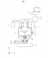
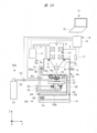
- FIG. 1 is an overall configuration diagram of the charged particle beam apparatus according to the first embodiment.
- the charged particle beam apparatus 1 is provided with a charged particle optical column 2 and a housing 3.
- a vacuum chamber 4 is defined by the charged particle optical column 2 and the housing 3.
- the charged particle optical column 2 is provided, for example, on the upper side of the casing 3 so that the lower part of the charged particle optical column 2 protrudes into the casing 3.
- the charged particle optical column 2 is attached to the housing 3 via a seal member (O-ring) 5, and the vacuum chamber 4 partitioned by the charged particle optical column 2 and the housing 3 is airtightly provided. ing.
- a vacuum pump (exhaust unit) 6 is provided outside the vacuum chamber 4 partitioned by the charged particle optical column 2 and the housing 3.
- the vacuum pump 6 is connected to the charged particle optical barrel 2 and the housing 3 by a vacuum pipe 7. That is, the vacuum pump 6 is connected to the vacuum chamber 4.
- the vacuum chamber 4 When using the charged particle beam apparatus 1, the vacuum chamber 4 is evacuated by the vacuum pump 6, and the pressure inside the vacuum chamber 4 is reduced to a vacuum. That is, the vacuum chamber 4 is evacuated by the vacuum pump 6, and the pressure inside the vacuum chamber 4 is maintained in a state where the pressure is reduced more than the pressure outside the vacuum chamber 4.
- vacuum pump (exhaust unit) 6 Although only one vacuum pump (exhaust unit) 6 is shown, there may be two or more.
- the casing 3 is provided with a leak valve 8.
- the leak valve 8 is for opening the vacuum chamber 4 defined by the charged particle optical column 2 and the housing 3 to the atmosphere.
- the leak valve 8 can open the interior of the housing 3 to the atmosphere during maintenance or the like.
- the leak valve 8 may be omitted or may be two or more.
- casing 3 is not restricted to the location shown by FIG. That is, the leak valve 8 may be arranged at another position of the housing 3.
- a charged particle source 9 and a charged particle optical system 10 are provided inside the charged particle optical column 2.
- the charged particle source 9 generates a charged particle beam.
- the charged particle beam apparatus 1 is an SEM
- the charged particle source 9 is an electron source that generates an electron beam, and includes, for example, an electron gun including a filament.
- the charged particle optical system 10 includes elements such as an optical lens 11.
- the charged particle optical system 10 focuses the charged particle beam generated by the charged particle source 9 and irradiates the sample 12 to scan the sample 12 as a primary charged particle beam. That is, the charged particle optical system 10 scans and irradiates the sample 12 with the charged particle beam generated by the charged particle source 9.
- a detector 13 is provided on a portion of the charged particle optical column 2 that protrudes into the housing 3.
- the detector 13 irradiates the sample 12 with a primary charged particle beam, thereby detecting secondary charged particles (secondary electrons or reflected electrons) emitted (generated) from the sample 12.
- the detector 13 can amplify and detect charged particles flying with energy of several keV to several tens keV, for example. Since the detector 13 is preferably thin and flat, the detector 13 is, for example, a semiconductor detector made of a semiconductor material such as silicon, or a signal from charged particles on the glass surface or inside is converted into light. A scintillator or the like that can be used can be used.
- a control unit 15 and a personal computer 16 are provided as the control system 14.
- the control unit 15 controls the vacuum pump (exhaust unit) 6 and the charged particle optical system 10.
- the personal computer 16 has a monitor on which an operation screen (Graphical User Interface: GUI) for operating the charged particle beam apparatus 1 is displayed, and an input for inputting commands to the operation screen from the user such as a keyboard and a mouse. Department.
- the personal computer 16 is connected to the control unit 15 through a communication line.
- the control unit 15 includes an analog circuit and a digital circuit, and converts the output signals of the vacuum pump 6, the charged particle source 9, the optical lens 11, and the detector 13 into digital image signals and supplies them to the personal computer 16. Send.
- the detector 13 may be connected to the control unit 15 via an amplifier 17 such as a preamplifier. At this time, an output signal from the detector 13 passes through the amplifier 17, for example. And sent to the control unit 15. Alternatively, if the amplifier 17 is unnecessary, the output signal from the detector 13 may not be sent to the control unit 15 via the amplifier 17.
- an amplifier 17 such as a preamplifier.
- control system 14 shown in FIG. 1 is merely an example. Therefore, the modified examples of the valve (not shown), the vacuum pump 6 or each communication line provided in the middle of the control unit 15 and the vacuum pipe 7 are not limited to the present embodiment unless departing from the gist of the first embodiment. It belongs to the range of the charged particle beam apparatus of aspect 1.
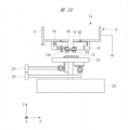
- FIG. 2 is a diagram illustrating a structure around the diaphragm element and the sample stage in the charged particle beam apparatus according to the first embodiment.
- the casing 3 is provided with a diaphragm element (diaphragm member) 18a.
- a diaphragm element 18 a is provided on the lower surface portion (wall portion of the vacuum chamber 4) 3 a of the housing 3, which is located below the charged particle optical column 2. Yes.
- the diaphragm element 18a includes a diaphragm (membrane, film part) 19 that transmits or passes the primary charged particle beam, and the space inside the vacuum chamber 4 and the vacuum chamber 4 Airtight isolation from the outside space.
- An opening 3b for transmitting or passing the primary charged particle beam is formed in a lower surface portion 3a of the housing 3 and below the charged particle optical column 2.
- the opening 3b is formed through the opening 3b.
- the diaphragm element 18a is attached so as to close it.
- a diaphragm (film part) 19 for transmitting or passing the primary charged particle beam is formed in the central part of the diaphragm element 18a.
- the peripheral portion of the diaphragm 19 is bonded to the lower surface portion 3a of the housing 3 and the peripheral portion of the opening 3b by the adhesive member 21, so that the lower surface portion 3a of the housing 3 is bonded. Is attached.
- the adhesive member 21 preferably hermetically seals between the diaphragm element 18 a and the lower surface portion 3 a of the housing 3.
- the adhesive member 21 is formed between the diaphragm element 18a and the lower surface portion 3a of the housing 3 in a state where the pressure inside the vacuum chamber 4 is lower than the pressure outside the vacuum chamber 4.
- the space is hermetically sealed.
- the adhesive member 21 adheres so that the diaphragm element 18a does not peel off from the lower surface portion 3a of the housing 3 even when the inside of the vacuum chamber 4 is returned to atmospheric pressure during maintenance of the charged particle beam apparatus 1. It is.
- a member containing a material such as silicon rubber, silver paste, vacuum grease, epoxy resin, or silicone resin can be used.
- a sample stage (holding unit) 22 is provided outside the vacuum chamber 4 defined by the charged particle optical column 2 and the housing 3 and below the diaphragm element 18a.
- the sample stage 22 is for holding the sample 12 outside the vacuum chamber 4.
- the sample stage 22 is assembled on the pedestal 23.
- a Z-axis drive unit 24 and an X and Y-axis drive unit 25 are provided outside the vacuum chamber 4.
- the Z-axis drive unit 24 moves and drives the sample stage 22 in, for example, the vertical Z-axis direction, and changes the height position of the sample stage 22, whereby the sample 12 and the diaphragm element 18 a held on the sample stage 22 are changed. The distance along the Z-axis direction is adjusted.
- the X and Y axis driving unit 25 moves and drives the sample stage 22 in, for example, the X axis direction and the Y axis direction, which are two directions intersecting each other in a horizontal plane, whereby the sample 12 held on the sample stage 22 is moved. Move in the X-axis direction and the Y-axis direction.
- the height position of the sample 12 is held so that the sample 12 is held on the sample stage 22 and the sample 12 is clearly observed using the Z-axis drive unit 24. Adjust. Further, by adjusting the X and Y axis driving unit 25, the X axis and Y axis driving unit 25 is moved to a desired place while observing the image of the sample 12.
- the Z-axis drive unit 24 moves and drives the sample stage 22, thereby increasing the distance along the Z-axis direction between the sample 12 held on the sample stage 22 and the diaphragm element 18 a. adjust.
- the Z-axis drive unit 24 moves the diaphragm element 18a together with the housing 3, for example, instead of the sample stage 22, so that the sample 12 held on the sample stage 22 and the diaphragm element 18a are moved in the Z-axis direction. You can also adjust the distance along.
- a vacuum chamber 4 partitioned by the charged particle optical column 2 and the housing 3 and hermetically provided is evacuated by a vacuum pump (exhaust unit) 6, thereby providing a vacuum.
- the pressure inside the chamber 4 is maintained in a state where the pressure is reduced more than the pressure of the space in which the sample 12 is disposed.
- the particle beam scans and irradiates the sample 12 held outside the vacuum chamber 4.
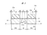
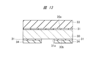
- FIG. 3 is a cross-sectional view of a main part of the diaphragm element according to the first embodiment.
- FIG. 4 is a plan view of the diaphragm element according to Embodiment 1 as viewed from the sample side.
- FIG. 3 is a cross-sectional view of the main part along the line AA in FIG.
- the diaphragm element 18 a is illustrated in a state where the diaphragm element 18 a is turned upside down when attached to the lower surface portion (wall portion of the vacuum chamber 4) 3 a (see FIG. 2) of the housing 3.
- the diaphragm element (diaphragm member) 18a includes a holding substrate (substrate) 30 as a base that supports the entire diaphragm element 18a.
- the holding substrate 30 has a main surface 30a and a main surface 30b that is a surface opposite to the main surface 30a.
- the main surface 30a faces the outside of the vacuum chamber 4 when the diaphragm element 18a is attached to the lower surface portion 3a of the housing 3 (see FIG. 2).
- the thin film 31 is formed on the main surface 30 a and the main surface 30 b of the holding substrate 30, that is, on both surfaces of the holding substrate 30.
- the thin film 31 formed on the main surface 30b of the holding substrate 30 is formed with an opening 31a that penetrates the thin film 31 and reaches the holding substrate 30. In the opening 31a, the holding substrate 30 is removed and the main surface is removed. A through hole 32 that reaches the main surface 30a from 30b is formed.
- the portion left so as to cover the opening 32 a of the through hole 32 in the main surface 30 a becomes the above-described diaphragm (membrane, film portion) 19. That is, the diaphragm 19 is formed on the main surface 30a so as to cover the opening 32a of the through hole 32 in the main surface 30a.
- the opening 31a is formed at a position corresponding to the central portion of the main surface 30b of the holding substrate 30 in plan view, and the through hole 32 is in the center of the holding substrate 30 in plan view. It is formed in the part. That is, the diaphragm 19 is formed at the center of the main surface 30a of the holding substrate 30 in plan view.
- the holding substrate (base body) 30 is preferably a semiconductor substrate (Si substrate) made of, for example, single crystal silicon (Si), and the orientation of the main surface 30a and the main surface 30b, that is, the substrate orientation is (100) or ( 110) can be used.
- Si substrate semiconductor substrate
- the through hole 32 can be easily formed in the holding substrate 30 by performing anisotropic etching using an etching solution made of an alkaline aqueous solution.
- the side surface of the through hole 32 to be formed is a (111) surface, the through hole 32 can be formed with high shape accuracy.
- a substrate whose both surfaces are mirror-finished can be used as the holding substrate 30, a substrate whose both surfaces are mirror-finished can be used. Thereby, it is possible to easily process both surfaces of the holding substrate 30.
- the thin film 31 may be formed on the entire surface of the main surface 30a of the holding substrate 30 as shown in FIGS. 3 and 4, but may be formed so as to cover at least the opening 32a of the through hole 32. That's fine.
- the thickness of the diaphragm 19 When the thickness of the diaphragm 19 is reduced, it becomes difficult to form the diaphragm 19 with a precise thickness dimension. On the other hand, when the thickness of the diaphragm 19 is increased, the primary charged particle beam passing through the inside of the vacuum chamber 4 and the secondary charged particles emitted from the sample 12 become difficult to pass through or pass through the diaphragm 19 and reach the sample 12. The amount of primary charged particle beams (irradiated) and the amount of secondary charged particles reaching (detected) the detector 13 are reduced. Therefore, the thickness of the diaphragm 19, that is, the thickness of the thin film 31, can be suitably set to 5 to 50 nm, for example.
- the thickness of the diaphragm 19 is further thinner, for example, 20 nm or less. That is, the thickness of the diaphragm 19 (thickness of the thin film 31) is more preferably 5 to 20 nm, for example.
- a film having tensile stress from the holding substrate 30 is preferable as the diaphragm 19, that is, the thin film 31.
- the film having such a tensile stress is preferably made of a material having a thermal expansion coefficient larger than that of the holding substrate 30 made of, for example, Si.
- a metal nitride such as silicon nitride (SiN) or aluminum nitride (AlN), or polyimide is preferable.
- the planar shape of the diaphragm (membrane part) 19, that is, the opening 32a of the through hole 32, is preferably a square or a regular octagon.
- the stress applied to the diaphragm 19 can be uniformly distributed in the main surface 30a.
- the diaphragm 19 is easily broken due to a pressure difference between the inside and the outside of the vacuum chamber 4. That is, as the area of the diaphragm 19 increases, the pressure resistance of the diaphragm 19 decreases.
- the planar shape of the opening 32a of the through-hole 32 is rectangular, and the length of the adjacent side is shortened so that the inside and the outside of the vacuum chamber 4 can be reduced. It is possible to prevent or suppress the diaphragm 19 from being broken due to the pressure difference therebetween.
- the side surface of the through hole 32 with respect to the main surface 30a (or main surface 30b) of the holding substrate 30 The angle formed by this is 54 to 55 °. Therefore, the width dimension d1 of the diaphragm 32, that is, the opening 32a of the through hole 32 is smaller than the width part d2 of the opening 31a formed in the thin film 31 on the main surface 30b, that is, the through hole 32. That is, the width dimension d2 of the through hole 32 is larger than the width dimension d1 of the diaphragm 19.
- the through hole 32 is formed with respect to the main surface 30a (or main surface 30b) of the holding substrate 30.
- the angle formed by the side surfaces is 90 °. Therefore, since the width dimension d2 of the through-hole 32 is equal to the width dimension d1 of the diaphragm 19, the diaphragm element 18a can be reduced in size.
- a pattern 33a made of a buffer film (film part) 33 is formed in a region other than the region 30c where the diaphragm (film part) 19 is formed.
- the buffer film 33 is higher than the diaphragm 19 (thin film 31) on the main surface 30a of the holding substrate 30, that is, along the Z-axis direction (the direction in which the primary charged particle beam is irradiated). It is formed so as to be located on the 12 side (on the sample stage 22 side).
- the buffer film 33 prevents the sample 12 held on the sample stage (holding unit) 22 and the diaphragm 19 from contacting each other.
- the buffer film 33 is formed on the main surface 30 a and on the thin film 31.
- the diaphragm element 18a and the sample 12 are in contact with each other. It's easy to do.
- the main surface 30a of the holding substrate 30 is closer to the sample 12 side (to the sample stage 22 side) than the diaphragm 19 along the Z-axis direction (direction in which the primary charged particle beam is irradiated).
- the buffer film 33 is formed so as to be positioned. Therefore, when the diaphragm element 18a and the sample 12 are in contact, the buffer film 33 and the sample 12 are in contact with each other, thereby preventing the diaphragm 19 and the sample 12 from being in contact with each other.
- the film thickness of the buffer film (film part) 33 depends on the thickness of the sample 12, but when the thickness of the sample 12 is less than 20 ⁇ m, for example, the upper limit value of the film thickness is set to 20 ⁇ m, for example.
- the value can be the thickness of the sample 12.
- the buffer film 33 is formed by a method suitable for forming a film having a relatively large film thickness such as a coating method, if the film thickness exceeds 20 ⁇ m, the in-plane of the main surface 30a of the holding substrate 30 In this case, the film thickness and the film quality may be uneven and the surface of the buffer film 33 may be uneven.
- the buffer film (film part) 33 an organic film, an inorganic film, or a metal film can be preferably used.
- the optimal material can be selected according to the thickness of the sample to be observed, the kind of charged particles, restrictions on the manufacturing process, and the like.
- polyimide can be used as the material of the buffer film 33.
- Polyimide can be easily formed and has excellent heat resistance and stability. Therefore, by using polyimide as the material of the buffer film 33, the buffer film 33 having excellent heat resistance and stability can be easily manufactured.
- the pattern 33a composed of the buffer film (film part) 33 is, in plan view, in two areas between the main surface 30a of the holding substrate (base body) 30 with the area 30c where the diaphragm (film part) 19 is formed. Is formed. As shown in FIG. 4, for example, when the planar shape of the diaphragm 19 is a square, the pattern 33 a made up of the buffer film 33 is preferably outside of at least two opposing sides of the four sides of the outer periphery of the diaphragm 19. Formed in the region.
- the pattern 33a formed of the buffer film 33 is preferably formed in at least two regions 30d and 30e located on the main surface 30a of the holding substrate 30 with the region 30c formed with the diaphragm 19 interposed therebetween in plan view. Is formed.
- the force applied to the main surface 30a of the holding substrate 30 is two regions 30d positioned across the region 30c where the diaphragm 19 is formed in plan view. , 30e can be evenly distributed.
- one of the diaphragm element 18a and the sample 12 is not inclined with respect to the other, and the diaphragm 19 and the sample 12 can be more reliably prevented from contacting each other.
- a gas lighter than air is supplied between the diaphragm element 18a and the sample 12 in the second embodiment to be described later.
- the flow path FP is preferably formed on the main surface 30a of the holding substrate 30 so as to cross from the one side to the opposite side through the region 30c where the diaphragm 19 is formed in plan view.
- the supplied gas can surely flow between the diaphragm 19 and the sample 12, so that the charged particle beam
- the S / N ratio of the image obtained by the apparatus can be improved.
- the buffer film 33 defines the region 30c in which the diaphragm 19 is formed.
- the pattern which consists of the buffer film 33 is integrally formed in the area
- the pattern including the buffer film 33 is integrally formed so as to surround three sides of the region 30 c where the diaphragm 19 is formed in a plan view.
- the pattern formed of the buffer film 33 is integrally formed so as to surround the four sides of the region 30 c where the diaphragm 19 is formed in a plan view is also included.
- the pattern 33a composed of the buffer film (film part) 33 is formed in a region farther from the outer periphery of the opening 32a of the through hole 32 in the main surface 30a than at the periphery in plan view. That is, the pattern 33a made of the buffer film 33 is formed in a region that is at least on the peripheral side of the region 30c where the diaphragm (film part) 19 is formed. Thereby, the pattern 33a made of the buffer film 33 can be prevented from overlapping the opening 32a, that is, the diaphragm 19 in a plan view, and the charged particle beam is applied to all portions of the diaphragm 19 formed so as to cover the opening 32a. Can be transmitted or passed.
- the pattern 33a formed of the buffer film (film part) 33 is separated from the peripheral edge of the holding substrate (base body) 30 by a predetermined width dimension d3 toward the diaphragm (film part) 19 side (to the center part side) in plan view. Formed in the region.
- the buffer film 33 is used as an alignment mark for aligning a dicing area (scribe area). be able to.
- the pattern 33 a made up of the buffer film (film part) 33 is farther from the peripheral side than the region 30 c where the diaphragm (film part) 19 is formed in a plan view, and more than the peripheral edge of the holding substrate (base body) 30. It is formed in regions 30d and 30e that are separated by a predetermined width dimension d3 toward the center.
- the preferred range of the width dimension d3 depends on the method of dicing the diaphragm element 18a.
- the preferred range of the width dimension d3 is, for example, 50 to 500 ⁇ m.
- the diaphragm 19 is less damaged and can be processed while maintaining the smoothness of the peripheral edge of the diaphragm element 18a, that is, the dicing surface. Therefore, for the width dimension d3, the dicing apparatus performs dicing. Smaller than When dicing with a laser, a suitable range of the width dimension d3 is, for example, 1 ⁇ m or more.
- the pattern 33a formed of the buffer film (film part) 33 has a predetermined width dimension d4 rather than the opening 31a of the thin film 31 on the main surface 30b, that is, the outer periphery of the through hole 32. It is formed in a region away from the edge side. Thereby, it is possible to prevent the buffer film 33 from being formed in a region overlapping the opening 31a, that is, the through hole 32 in a plan view. In other words, the buffer film 33 can be prevented from being formed in the portion of the holding substrate 30 with a low strength where the through hole 32 is formed and the thickness is reduced.
- the width dimension d4 can be set to about 0 to 500 ⁇ m, for example.
- the pattern 33a formed of the buffer film 33 is formed in a region farther to the peripheral side than the outer periphery of the opening 31a when the stress of the buffer film 33 may affect the diaphragm 19. . Therefore, when the stress of the buffer film 33 is extremely small, the pattern 33a made of the buffer film 33 is a region farther to the peripheral side than the region 30c in which the diaphragm 19 is formed in plan view, and has an opening portion. It can also be formed in a portion within 31a. In this case, the buffer film 33 can be formed in a region separated from the region 30c in which the diaphragm 19 is formed by, for example, 1 ⁇ m or more on the peripheral side.
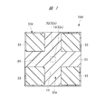
- 5 to 7 are plan views of the diaphragm elements of the first to third modifications of the first embodiment as viewed from the sample side. 5 to 7 show diaphragm elements 18b to 18d having different pattern shapes of the buffer film 33 in plan view, respectively.
- the planar shape of the diaphragm (film part) 19 is a square, and the pattern is formed of the buffer film (film part) 33.
- 33b is formed in the area
- the pattern 33b made of the buffer film 33 is integrally formed so as to surround three sides of the region 30c in which the diaphragm 19 is formed in a plan view.
- the number of sides on which the buffer film 33 is formed outside the four sides of the outer periphery of the diaphragm 19 is three.
- the diaphragm element 18a shown in FIG. More than the number of sides (two) on which the buffer film 33 is formed. Therefore, the diaphragm element 18b can prevent the diaphragm 19 and the sample 12 from contacting each other more reliably than the diaphragm element 18a when moving the sample 12 having an uneven surface.
- the planar shape of the diaphragm (film part) 19 is a square, and the pattern is composed of the buffer film (film part) 33.
- 33c is formed in the area
- the pattern 33c made of the buffer film 33 is integrally formed so as to surround the four sides of the region 30c in which the diaphragm 19 is formed in a plan view.
- the diaphragm element 18c shown in FIG. 6 the number of sides on which the buffer film 33 is formed outside the four sides of the outer periphery of the diaphragm 19 is four. In the diaphragm element 18b shown in FIG. More than the number of sides (three) on which the buffer film 33 is formed. Therefore, the diaphragm element 18c can prevent the diaphragm 19 and the sample 12 from contacting each other more reliably than the diaphragm element 18b when moving the sample 12 having an uneven surface.
- the planar shape of the diaphragm 19 is square, and the pattern 33d made of the buffer film (film part) 33 is formed as a diaphragm. It is divided into four locations on the outer side along the diagonal direction with respect to 19 vertices.
- the buffer film 33 is not formed in a region outside any of the four sides on the outer periphery of the diaphragm 19. That is, the buffer film 33 is removed in a cross-shaped region intersecting with the region 30c where the diaphragm 19 is formed.
- Such a cross-shaped region from which the buffer film 33 is removed is the gas supplied when a gas lighter than air is supplied between the diaphragm element 18d and the sample 12 in the second embodiment to be described later.
- This flow path FP is composed of two flow paths that intersect each other and are formed so as to cross from the one side to the opposite side through the region 30c in which the diaphragm 19 is formed on the main surface 30a in plan view. It is preferable.
- the supplied gas can surely flow between the diaphragm 19 and the sample 12, so that the charged particle beam
- the S / N ratio of the image obtained by the apparatus can be improved.
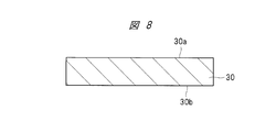
- 8 to 14 are cross-sectional views of a main part during the manufacturing process of the diaphragm element according to the first embodiment. 8 to 14 show cross sections corresponding to FIG.
- a holding substrate (base body) 30 having a main surface 30a and a main surface 30b opposite to the main surface 30a is prepared.
- a Si substrate having a substrate orientation (100) or (110) can be used as the holding substrate 30.
- through-holes 32 can be easily formed in the holding substrate 30 by performing anisotropic etching using an etching solution made of an alkaline aqueous solution.
- a substrate whose both surfaces are mirror-finished can be used as the holding substrate 30. Thereby, it is possible to easily process both surfaces of the holding substrate 30.
- FIG. 8 only the region where one diaphragm element is formed in the holding substrate 30 is illustrated, but actually, the holding substrate 30 is along a direction parallel to the main surface 30a or the main surface 30b. This includes a region where a plurality of diaphragm elements are formed (the same applies to FIGS. 9 to 14).
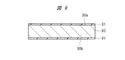
- the thin film 31 is formed on both surfaces of the holding substrate (base body) 30, that is, the main surface 30a and the main surface 30b.
- a SiN film can be formed as the thin film 31 at a temperature of 700 ° C. by a chemical vapor deposition (CVD) method.
- the thickness of the thin film 31 is preferably, for example, 5 to 50 nm, and more preferably, for example, 5 to 20 nm. Further, as described above, the thin film 31 is preferably a film having tensile stress, and is preferably made of a metal nitride such as SiN or AlN, or polyimide.
- the diaphragm 19 is sintered to increase the density and improve the rigidity, so that the pressure resistance of the diaphragm 19 is improved.
- the heat treatment temperature is preferably 800 ° C. or higher.
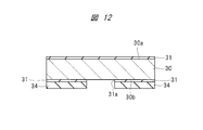
- the insulating film 34 is formed on both surfaces of the holding substrate (base) 30 having the thin film 31 formed on both surfaces, that is, the main surface 30a and the main surface 30b.
- the thin film 31 can be protected until the diaphragm 19 is formed by a process described later, and the thin film 31 can be prevented or suppressed from being damaged.
- a silicon oxide (SiO 2 ) film can be formed as the insulating film 34 by CVD.
- the insulating film 34 can be formed only on the main surface 30 a on which the diaphragm 19 is formed, on both surfaces of the holding substrate 30.
- insulating films 34 are formed on both the main surface 30 a and the main surface 30 b of the holding substrate 30.
- openings 31 a are formed in the insulating film 34 and the thin film 31 on the main surface 30 b of the holding substrate (base body) 30.
- the insulating film 34 and the thin film 31 are removed by, for example, photolithography and etching. Thereby, an opening 31 a that penetrates the insulating film 34 and the thin film 31 and reaches the holding substrate 30 is formed. In the opening 31a, the holding substrate 30 is exposed.
- the insulating film 34 is removed from the main surface 30 a of the holding substrate (base body) 30. As a result, the thin film 31 is exposed on the main surface 30 a of the holding substrate 30.
- a buffer film (film part) 33 is formed on the main surface 30 a of the holding substrate (base body) 30.
- the buffer film 33 can be formed of an organic film, an inorganic film, or a metal film.
- the material of the organic film for example, polyimide can be used.
- the film thickness of the buffer film 33 depends on the thickness of the sample 12, but when the thickness of the sample 12 is less than 20 ⁇ m, for example, the upper limit value of the film thickness is set to 20 ⁇ m and the lower limit value of the film thickness is set to, for example. It can be the thickness of the sample.
- a part of the buffer film (film part) 33 is removed by a photolithography technique and etching, and a pattern 33a made of the buffer film 33 is formed.
- the pattern 33a made of the buffer film 33 is formed in a region separated from the peripheral edge of the holding substrate (base body) 30 by a predetermined width dimension d3 on the side of the diaphragm 19 (on the center side) in plan view. Thereby, when the diaphragm element 18a is diced and separated into individual pieces in a later step, the buffer film 33 can be used as an alignment mark for aligning the scribe region.
- the pattern 33a made of the buffer film 33 is formed in a region separated from the outer periphery of the opening 31a by a predetermined width dimension d4 toward the peripheral side.
- a predetermined width dimension d4 toward the peripheral side.
- a resin film (not shown) can be applied to cover the entire surface of the holding substrate 30.
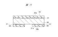
- a through hole 32 (see FIG. 3) is formed in the holding substrate (base body) 30.
- anisotropic etching using an etching solution made of an alkaline aqueous solution is performed using the thin film 31 with the opening 31a formed as a mask to remove the holding substrate 30 exposed to the opening 31a. (Etching).
- a through hole 32 (see FIG. 3) that reaches the main surface 30a from the main surface 30b is formed in the holding substrate 30.
- an etching solution made of an alkaline aqueous solution such as an aqueous potassium hydroxide (KOH) solution or an aqueous tetramethylammonium hydroxide (TMAH) solution is used.
- KOH potassium hydroxide
- TMAH aqueous tetramethylammonium hydroxide
- the main surface 30a covers the opening 32a (see FIG. 3) of the through hole 32.
- a diaphragm 19 composed of the thin film 31 left on the film is formed.
- the holding substrate 30 is diced in the scribe region to be separated into individual pieces, whereby the diaphragm element 18a as shown in FIG. 3 is formed.
- the height of the main surface 30b may be adjusted by a back grinding method or the like before dicing. In that case, the main surface 30b has a structure in which the holding substrate 30 is exposed.
- the insulating film 34 is formed on the main surface 30b as shown in FIG. 14, before the through hole 32 is formed or the through hole 32 is formed. After that, the insulating film 34 is removed with an etchant such as hydrofluoric acid (HF).
- HF hydrofluoric acid
- the holding substrate (base body) 30 When a Si substrate with a substrate orientation of (100) or (110) is used as the holding substrate (base body) 30 and anisotropic etching is performed, the side surface of the through-hole 32 to be formed becomes the (111) surface, so The hole 32 can be formed with high shape accuracy.
- the width dimension d1 (see FIG. 3) of the diaphragm (film part) 19, that is, the opening 32a of the through hole 32 is larger than the opening 31a formed in the thin film 31 on the main surface 30b, that is, the width dimension d2 of the through hole 32.
- the width dimension d2 of the through hole 32 is larger than the width dimension d1 of the diaphragm 19.
- the angle formed by the side surface of the through hole 32 with respect to the main surface 30a (or main surface 30b) of the holding substrate 30 is 90 °. . Therefore, since the width dimension d2 of the through hole 32 is equal to the width dimension d1 of the diaphragm (film part) 19, the diaphragm element 18a can be reduced in size.
- the pattern 33a formed of the buffer film (film part) 33 is formed in a region farther to the peripheral side than the outer periphery of the opening 31a because the stress of the buffer film 33 may affect the diaphragm 19. It is the case. Therefore, when the stress of the buffer film 33 is extremely small, as described above, the pattern 33a made of the buffer film 33 is more peripheral than the region 30c (see FIG. 4) where the diaphragm 19 is formed in plan view. It can also be formed in a portion in the opening portion 31a. In this case, the buffer film 33 can be formed in a region separated from the region 30c in which the diaphragm 19 is formed by, for example, 1 ⁇ m or more on the peripheral side.
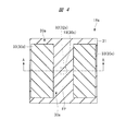
- FIG. 15 is a cross-sectional view of relevant parts showing a diaphragm element according to a fourth modification of the first embodiment.
- the buffer film 33 is directly formed on the thin film 31 on the main surface 30 a of the holding substrate 30.
- the buffer film (film part) 33 is a thin film on the main surface 30 a of the holding substrate (substrate) 30.
- An insulating film 34 is formed on 31. That is, the pattern 33 a made of the buffer film 33 is formed on the thin film 31 via the pattern 34 a made of the insulating film 34.
- the pattern 34a made of the insulating film 34 is the same pattern as the pattern 33a made of the buffer film 33 in plan view.
- the buffer film 33 made of an organic film such as polyimide, an inorganic film, or a metal film is directly formed on the thin film 31 made of, for example, SiN, the adhesiveness (adhesive force) between the buffer film 33 and the thin film 31 is improved. May be weak.
- the buffer film 33 made of an organic film such as polyimide, an inorganic film, or a metal film is formed on the thin film 31 made of, for example, SiN via the insulating film 34 made of, for example, SiO 2 , the buffer film 33 is formed. It is possible to improve the adhesion (adhesion) between the thin film 31 and the thin film 31.
- the insulating film 34 is removed on the main surface 30a of the holding substrate 30 as shown in FIG. .
- the insulating film 34 is not removed on the main surface 30a of the holding substrate 30 after the opening 31a is formed as shown in FIG.
- the buffer film 33 is formed on the main surface 30 a of the holding substrate 30. Then, a part of the buffer film 33 is removed by photolithography technique and etching to form a pattern 33a composed of the buffer film 33, and then the insulating film 34 is removed in a region where the pattern 33a is not formed. A pattern 34 a composed of 34 is formed.
- a resin film (not shown) is formed, and the holding substrate 30 exposed to the opening 31a is removed by anisotropic etching (etching). A through hole 32 is formed. Thereby, the diaphragm element 18e shown in FIG. 15 is formed.
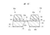
- FIG. 16 is a cross-sectional view of relevant parts showing a diaphragm element according to a fifth modification of the first embodiment.
- the pattern 34a made of the insulating film 34 is the same pattern as the pattern 33a made of the buffer film 33 in plan view.
- the pattern 34b made of the insulating film 34 is more than the region where the pattern 33a made of the buffer film 33 is formed. It is formed up to the region on the side of the diaphragm 19 (center side) by the width dimension d5. Note that the region where the pattern 34 b is formed is farther from the periphery than the region 30 c (see FIG. 4) where the diaphragm (film part) 19 is formed, and more than the periphery of the holding substrate (base body) 30. It is included in the area away from the center.
- the region where the insulating film 34 is formed is expanded toward the diaphragm 19 (to the center) than the diaphragm element 18e according to the fourth modification of the first embodiment.
- the insulating film 34 formed in the expanded region also prevents the diaphragm 19 and the sample 12 from contacting each other. Therefore, the diaphragm element 18f can further enhance the function of preventing the diaphragm 19 and the sample 12 from coming into contact with each other compared to the diaphragm element 18e.
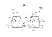
- FIG. 17 is a main part sectional view showing a diaphragm element according to a sixth modification of the first embodiment.
- the diaphragm element (diaphragm member) 18 g of the sixth modification of the first embodiment is a pattern comprising the buffer film (film part) 33 in the diaphragm element (diaphragm member) 18 a of the first embodiment.
- a sealing film (film part) 35 made of a conductive film is formed on 33a. That is, the seal film 35 made of a conductive film is formed on the surface of the pattern 33 a made of the buffer film 33.
- the sealing film 35 may also be formed on the side surface 30 f of the holding substrate (base body) 30. That is, the seal film 35 is integrally formed on the surface of the pattern 33 a made of the buffer film 33 and the side surface 30 f of the holding substrate 30. Thereby, as will be described in the second embodiment to be described later, it is possible to further prevent a decrease in sensitivity due to accumulation of secondary charged particles in the buffer film 33 or the diaphragm 19. Further, when the seal film 35 is not formed on the side surface 30f, secondary charged particles are formed on the buffer film 33 and the diaphragm 19 by using silver paste or a conductive seal so that the housing 3 and the seal film 35 are electrically connected. Prevent accumulation.
- the seal film 35 is made of a metal such as aluminum (Al), copper (Cu), tungsten (W), titanium (Ti), tantalum (Ta), chromium (Cr), nickel (Ni), or molybdenum (Mo).
- a conductive film can be used.
- a conductive film made of a metal nitride such as tungsten nitride (WN) or titanium nitride (TiN) or a metal compound such as tungsten silicide (WSi) or nickel silicide (NiSi) is used as the seal film 35. it can.
- a shielding plate is disposed so as to mask the diaphragm 19, A seal film 35 made of a conductive film is formed by vapor deposition.
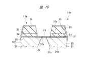
- FIG. 18 is a cross-sectional view of relevant parts showing a diaphragm element according to a seventh modification of the first embodiment.
- the diaphragm element (diaphragm member) 18h according to the seventh modification of the first embodiment is the same as the buffer element (membrane part) in the diaphragm element (diaphragm member) 18e according to the fourth modification of the first embodiment.
- a sealing film (film part) 35 made of a conductive film is formed on the pattern 33a made of 33). That is, the seal film 35 made of a conductive film is formed on the surface of the pattern 33 a made of the buffer film 33.
- the seal film 35 may also be formed on the side surface 30 f of the holding substrate (base body) 30.
- a conductive film made of a metal such as Al, Cu, W, Ti, Ta, Cr, Ni, or Mo can be used as in the sixth modification of the first embodiment.
- a conductive film made of a metal nitride such as WN or TiN, or a metal compound such as WSi or NiSi can be used as in the sixth modification of the first embodiment.
- a shielding plate is disposed so as to mask the diaphragm 19
- the sealing film 35 made of a conductive film is formed by sputtering or vapor deposition.
- the diaphragm element (diaphragm member) 18e of the fourth modified example of the first embodiment is arranged on the pattern 33a made of the buffer film 33.
- a sealing film 35 made of a conductive film can be formed.
- FIG. 19 is a flowchart showing a part of an observation process by the charged particle beam apparatus according to the first embodiment.
- the vacuum chamber 4 is evacuated (step S11).
- the vacuum chamber 4 defined by the charged particle optical column 2 and the housing 3 is evacuated through the vacuum pipe 7 by the vacuum pump (exhaust unit) 6 controlled by the control unit 15, for example.
- the pressure inside the vacuum chamber 4 is reduced to a vacuum. Therefore, the vacuum chamber 4 is in a state where the pressure inside the vacuum chamber 4 is reduced more than the pressure outside the vacuum chamber 4, that is, in a state where a pressure difference is generated between the inside and the outside of the vacuum chamber 4. Maintained.
- the sample 12 is held by the sample stage (holding unit) 22 (step S12).
- the sample 12 is placed on the sample stage 22 and held.
- the sample stage is controlled by, for example, the Z-axis driving unit 24 controlled by the control unit 15 so that the sample stage (holding unit) 22 or the sample 12 held on the sample stage 22 does not contact the diaphragm element (diaphragm member) 18a.
- the height position of 22 in the Z-axis direction is sufficiently lowered.
- a charged particle beam is generated (step S13).
- a charged particle beam is generated by the charged particle source 9 made of an electron gun including a filament, for example.
- step S14 observation of the sample 12 is started (step S14).
- the conditions of the optical lens 11 of the charged particle optical system 10 are adjusted, an image of the sample 12 is displayed on the personal computer 16, and observation is started.
- the magnification is set to a low magnification so that the next focusing can be performed smoothly.
- step S15 focusing is performed by adjusting the Z axis.
- step S15 while observing the image of the sample 12, the height position of the sample 12 is gradually raised using the Z-axis drive unit 24, and the focus is adjusted so that the sample 12 is clearly observed.
- a desired observation place is set by adjusting the X and Y axes (step S16).
- the sample 12 is moved to a desired observation location by using the X and Y axis drive unit 25.
- step S17 magnification adjustment and fine focus adjustment are performed.
- the magnification is adjusted and the Z-axis drive unit 24 is finely adjusted.
- step S18 image acquisition is started (step S18).
- the image acquisition switch is pressed, the image is acquired by the personal computer 16, and the acquired image is stored. Then, by repeating this operation a plurality of times, desired observation is performed on the sample 12 and an image is acquired.
- step S19 the sample 12 is taken out (step S19).
- step S19 after the observation is completed, the height position of the sample 12 is lowered using the Z-axis drive unit 24, the sample 12 is moved away from the diaphragm element 18a, and then the sample stage (holding unit) 22 and the sample 12 are moved. Take out.
- the operations in steps S12 to S19 are repeated for the next sample.
- the flow of the observation process shown in FIG. 19 shows an example of the operation of the charged particle beam apparatus, and the order of each process is not limited to the order shown in FIG. Therefore, the order of the steps S11 to S19 can be changed as appropriate.
- ⁇ Damage to diaphragm> For example, in the SEM having the same structure as the SEM described in Patent Document 1, the sample is placed on the diaphragm. In this case, since the diaphragm is thin, it is difficult to increase the area of the diaphragm, and the sample can be observed only in the region where the diaphragm is formed. Therefore, it is necessary to mount the sample on the diaphragm many times until the part to be observed is mounted on the diaphragm. In addition, since the diaphragm is thin, the diaphragm may be damaged when the sample is exchanged or when the sample is placed on the diaphragm. If the diaphragm is damaged, the sample or the atmosphere may enter the charged particle optical column arranged below, and the charged particle source may break down.
- the diaphragm element when the diaphragm element is attached to the charged particle beam device or replaced, the diaphragm element falls on another member or approaches the other member, so that the diaphragm and the other member are It is easy to contact and the diaphragm is easily damaged.
- the focal length fluctuates due to the change in the composition or pressure of the gas. That is, when the pressure outside the vacuum chamber is larger than the pressure inside the vacuum chamber and there is a pressure difference between the inside and the outside of the vacuum chamber, the focal length is likely to fluctuate. Therefore, it is necessary to adjust the distance between the diaphragm element and the sample every time an observation image is taken, and the diaphragm and the sample are more likely to come into contact with each other, and the diaphragm is more likely to be damaged.
- Patent Document 2 relates to a measurement method using a STEM mode that detects an electron beam that passes through a sample.
- the sample and the spacer are brought into contact with each other, and the operating distance is determined by the height of the spacer. The maximum resolution is achieved.
- the spacer disposed around the aperture keeps the distance between the diaphragm and the sample constant, and does not prevent the diaphragm and the sample from contacting each other. .
- the diaphragm and the sample are easily in contact with each other, the diaphragm is likely to be damaged, and an observation image cannot be stably captured with high resolution, so that the performance of the charged particle beam apparatus is deteriorated.
- the diaphragm element 18 a has the inside of the vacuum chamber 4 in a state where the pressure inside the vacuum chamber 4 is reduced more than the pressure outside the vacuum chamber 4.
- a diaphragm 19 is formed that airtightly isolates the outside from the outside and transmits charged particle beams.
- the diaphragm element 18a has a buffer film (film part) 33 that prevents the sample 12 held on the sample stage (holding part) 22 from contacting the diaphragm 19 along the Z-axis direction. It is formed so as to be located closer to the sample 12 side (to the sample stage 22 side) than 19.
- the buffer film 33 when the buffer film 33 is formed on the diaphragm element 18a, the buffer film 33 and the sample 12 come into contact when the sample 12 approaches the diaphragm element 18a. Therefore, it can prevent that the diaphragm 19 and the sample 12 contact, and can prevent that the diaphragm 19 is damaged. Therefore, since an observation image can be captured stably with high resolution, the performance of the charged particle beam apparatus is improved.
- the buffer film 33 and Contact with other members can prevent that the diaphragm 19 and another member contact, and can prevent that the diaphragm 19 is damaged.
- the diaphragm element 18a and the sample 12 The focal length fluctuates due to a change in the composition or pressure of the gas existing between the two. That is, when the pressure outside the vacuum chamber 4 is larger than the pressure inside the vacuum chamber 4 and there is a pressure difference between the inside and the outside of the vacuum chamber 4, the focal length is likely to fluctuate. Therefore, it is necessary to adjust the distance between the diaphragm element 18a and the sample 12 every time an observation image is taken.
- the diaphragm element includes an attachment for mounting the holding substrate (base), and the attachment to which the holding substrate is mounted is attached to the lower surface portion of the housing. is there. Therefore, in the charged particle beam apparatus of the second embodiment, each part other than the attachment is the same as each part in the charged particle beam apparatus of the first embodiment, and the description thereof is omitted. In addition, the effects of the charged particle beam apparatus according to the second embodiment other than the attachment are the same as the effects of the charged particle beam apparatus according to the first embodiment, and the description thereof is omitted.
- the diaphragm element (diaphragm member) 18h according to the seventh modification of the first embodiment shown in FIG. 18 is used as the diaphragm element.
- the diaphragm element 18a of the first embodiment and the diaphragm elements 18b to 18g of the first to sixth modifications of the embodiment may be used instead of the diaphragm element 18h.
- FIG. 20 is a diagram showing a structure around the diaphragm element and the sample stage in the charged particle beam apparatus according to the second embodiment.
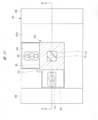
- FIG. 21 is a plan view of the attachment of the second embodiment as viewed from the sample side.
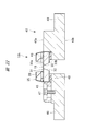
- FIG. 22 is a cross-sectional view of the principal part along the line BB in FIG.
- the holding substrate 30 of the diaphragm element 18h is detachably attached to the attachment (diaphragm holding member, attachment body) 40.
- a support portion 41 that supports an attachment (mounting body) 40 is formed on the lower surface portion (wall portion of the vacuum chamber 4) 3 a of the housing 3.
- the support part 41 and the attachment 40 have a cross-sectional shape including a concavo-convex shape corresponding to each other.
- the attachment 40 can be easily attached to the support part 41, without dropping, by sliding the attachment 40 toward the back
- a stopper (not shown) for stopping the attachment 40 at a predetermined position is provided on the lower surface portion 3a of the housing 3 on the back side of the paper surface of the support portion 41 in FIG.
- the stopper (not shown) includes an opening 3b formed in the lower surface 3a of the housing 3 when the attachment 40 is stopped at a predetermined position, and a diaphragm element 18h in which the holding substrate 30 is attached to the attachment 40. Are provided so as to overlap with each other in a plan view.
- the attachment (mounting body) 40 is preferably made of a material containing metal.
- the attachment 40 and the housing 3 can be electrically connected with low resistance, and the potential of the attachment 40 and the potential of the housing 3 are made equipotential. can do. Further, when the casing 3 is grounded and the potential of the casing 3 is 0 potential (earth), the potential of the attachment 40 can be 0 potential (ground).
- a seal member 42 is provided between the housing 3 and the attachment 40.
- the seal member 42 hermetically seals between the housing 3 and the attachment 40.
- an O-ring can be used as the seal member 42.
- the housing 3 and the attachment 40 are brought into contact with each other in a state where vacuum grease is applied between the housing 3 and the attachment 40, so that the space between the housing 3 and the attachment 40 is provided. It can also be hermetically sealed.
- the attachment (mounting body) 40 has a main surface 40a and a main surface 40b opposite to the main surface 40a.
- a recess 43 is provided in the center of the attachment 40, and the holding substrate 30 of the diaphragm element (diaphragm member) 18h is easily detachably attached to the recess 43.
- holding jigs 44 and 45 that are slidable in the vertical and horizontal directions in FIG. 21 are provided, respectively. Screws 46 and 47 for fixing 45 are provided.
- a seal member 48 is provided between the bottom surface of the recess 43 and the holding substrate 30 attached to the recess 43.
- the seal member 48 hermetically seals between the attachment 40 and the holding substrate 30.
- a soft material can be used so that the attachment 40 and the holding substrate 30 can be hermetically sealed, and the attachment 40 and the holding substrate 30 are not damaged.
- an O-ring can be used.
- the attachment 40 and the holding substrate 30 can be hermetically sealed by contacting the attachment 40 and the holding substrate 30 with vacuum grease applied. .
- the holding substrate 30 of the diaphragm element 18h is attached to the attachment 40, the holding substrate 30 is attached to the recess 43, and the holding jigs 44 and 45 are slid, so that the holding substrate 30 is shown in FIG. 21 is pressed to the lower side and the right side.
- the holding substrate 30 is fixed with screws 46 and 47 in a state where the holding substrate 30 is pressed against the recess 43.
- guides 49 are provided on the left and right sides of the center of the attachment 40.
- the guide 49 is for attaching the attachment 40 to which the holding substrate 30 is mounted to the support portion 41 without dropping.
- the guide 49 is formed so that the support portion 41 and the attachment 40 have a cross-sectional shape including a concavo-convex shape corresponding to each other.
- the main surface 30a of the holding substrate 30 forms the same surface as the main surface 40a of the attachment 40, or The main surface 30a protrudes on the main surface 40a. Thereby, it can prevent that the sample 12 hold
- the holding jigs 44 and 45 are preferably made of a conductive material.
- a conductive material as the material of the pressing jigs 44 and 45, the sealing film (film part) 35, the pressing jigs 44 and 45, and the attachment 40 can be electrically connected with low resistance.
- secondary charged particles emitted from the sample 12 that have not permeated or passed through the diaphragm 19 can be released to the outside of the diaphragm element via the seal film 35, the holding jigs 44 and 45, and the attachment 40. it can. Therefore, it is possible to prevent a decrease in sensitivity due to accumulation of secondary charged particles in the buffer film 33 or the diaphragm 19.
- the seal film 35 when the seal film 35 is also formed on the side surface 30f of the holding substrate (substrate) 30, the seal film 35 and the pressing jig 44, 45 can be electrically connected with lower resistance. Therefore, it is possible to further prevent a decrease in sensitivity due to accumulation of secondary charged particles in the buffer film 33 or the diaphragm 19.
- the charged particle beam apparatus according to the third embodiment is obtained by adding a supply unit that supplies gas to the charged particle beam apparatus according to the first embodiment. Therefore, in the charged particle beam apparatus according to the third embodiment, each part other than the supply unit is the same as each part in the charged particle beam apparatus according to the first embodiment, and a description thereof is omitted. In addition, the effects of the charged particle beam apparatus of the third embodiment other than the supply unit are the same as the effects of the charged particle beam apparatus of the first embodiment, and the description thereof is omitted.
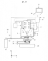
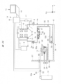
- FIG. 23 is an overall configuration diagram of the charged particle beam apparatus according to the third embodiment.
- a supply unit 50 for supplying gas is provided between the diaphragm element (diaphragm member) 18a and the sample 12.
- the supply unit 50 includes a gas cylinder 51, a gas supply pipe 52, and a gas control valve 53.
- the gas cylinder 51 is provided outside the vacuum chamber 4.
- One end of the gas supply pipe 52 is connected to the gas cylinder 51, and the other end of the gas supply pipe 52 opens near the diaphragm element 18a.
- a gas control valve 53 is provided in the middle of the gas supply pipe 52, and the opening / closing operation and the opening degree of the gas control valve 53 are controlled by the control unit 15.
- gas is supplied between the diaphragm element 18a and the sample 12 via the gas supply pipe 52 by controlling the opening / closing operation and the opening degree of the gas control valve 53 by the control unit 15. Can do.
- gas cylinder 51 may be prepared as a part of the charged particle beam apparatus 1b, but may be prepared separately from the charged particle beam apparatus 1b.
- the primary charged particle beam that has passed through or passed through the diaphragm (film part) 19 and the secondary charged particles emitted from the sample 12 are gas molecules contained in the air. It is scattered by. Therefore, the amount of the primary charged particle beam that reaches the sample 12 decreases, and the amount of the secondary charged particle that reaches the detector 13 decreases.
- a gas composed of gas molecules having a molecular weight smaller than the average molecular weight of air for example, a gas lighter than air
- a gas that is lighter than air such as nitrogen (N 2 ) gas or water vapor gas
- N 2 nitrogen
- water vapor gas a gas having a molecular weight smaller than that of N 2 gas or water vapor gas, such as helium (He) gas or hydrogen (H 2 ) gas
- He helium
- H 2 hydrogen
- the observation process by the charged particle beam device 1b according to the third embodiment is performed except that the processes in steps S15 to S18 in FIG. 19 are performed while gas is supplied between the diaphragm element 18a and the sample 12. It can carry out similarly to the observation process by the charged particle beam apparatus 1 of Embodiment 1.
- the charged particle beam apparatus according to the first embodiment includes a charged particle optical barrel and a casing, and the vacuum chamber is partitioned by the charged particle optical barrel and the casing.
- the charged particle beam device according to the fourth embodiment includes a second housing in addition to the charged particle optical column and the first housing, and the second housing is mounted on the first housing.
- the vacuum chamber is defined by the charged particle optical column, the first casing, and the second casing.
- the charged particle beam apparatus according to the fourth embodiment is applied to a desktop scanning electron microscope.
- the charged particle beam apparatus according to the fourth embodiment can be applied to other various charged particle beam apparatuses such as an ion microscope.
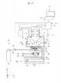
- FIG. 24 is an overall configuration diagram of a scanning electron microscope according to the fourth embodiment.
- a scanning electron microscope (charged particle beam device) 1c includes a charged particle optical column 2, a housing 3c, and a housing member (charged particle beam device member) 56.
- the casing member 56 includes a casing 55, a diaphragm element (diaphragm member) 18 a, a sample stage (holding section) 22, a Z-axis driving section 24, and a lid member 57.
- the charged particle optical column 2 in the fourth embodiment also has, for example, an upper side of the housing 3c and a lower portion of the charged particle optical column 2 of the housing 3c. It is provided so as to protrude inside.
- the charged particle optical column 2 is attached to the housing 3c via a seal member (O-ring) 5, and the housing 55 is attached to the housing 3c via a seal member (O-ring) 5a. . Therefore, the vacuum chamber 4a defined by the charged particle optical barrel 2, the housing 3c, and the housing 55 is provided in an airtight manner.
- an opening 3e is provided in, for example, the side surface 3d of the housing 3c.
- the housing 55 is provided integrally with the side surface portion 55a provided so as to close the opening 3e and the side surface portion 55a, for example, from the opening 3e of the housing 3c toward the center of the housing 3c.
- a recess 55b provided to retract.
- the recess 55b is provided such that the sample chamber 58 defined by the recess 55b is positioned below the charged particle optical column 2 when the housing 55 is attached to the housing 3c.
- the casing 55 is provided with a lid member 57.
- the lid member 57 is detachably attached to the housing 55, and the sample chamber 58 is partitioned by the housing 55 and the lid member 57 by attaching the lid member 57 to the housing 55.
- the space inside the sample chamber 58 is a space outside the vacuum chamber 4a.
- the lid member 57 is attached to the housing 55 via a seal member (O-ring) 59. Therefore, the sample chamber 58 partitioned by the housing 55 and the lid member 57 is provided in an airtight manner.
- the lid member 57 is attached to the side surface portion 55a of the housing 55 via a seal member 59, and the sample chamber 58 is partitioned by the lid member 57 and the recess 55b. Further, as will be described later with reference to FIG. 26, the lid member 57 is removed from the housing 55 by sliding (moving) to the left from the position shown in FIG. 24.
- a vacuum pump (exhaust unit) 6 is provided outside the vacuum chamber 4a defined by the charged particle optical column 2, the casing 3c, and the casing 55.
- the vacuum pump 6 is connected to the charged particle optical barrel 2 and the housing 3c by a vacuum pipe 7. That is, the vacuum pump 6 is connected to the vacuum chamber 4a.
- the vacuum chamber 4a When using the scanning electron microscope (charged particle beam apparatus) 1c, the vacuum chamber 4a is evacuated by the vacuum pump 6, and the pressure inside the vacuum chamber 4a is reduced to a vacuum. That is, the vacuum chamber 4a is evacuated by the vacuum pump 6, and the pressure inside the vacuum chamber 4a is maintained in a state where the pressure is reduced more than the pressure outside the vacuum chamber 4a.
- a leak valve 8 is provided in the housing 3c, as in the first embodiment.
- the leak valve 8 is for opening the vacuum chamber 4a defined by the charged particle optical barrel 2, the casing 3c, and the casing 55 to the atmosphere.
- the configurations of the charged particle optical column 2 and the control system 14 can be the same as those of the charged particle optical column 2 and the control system 14 in the charged particle beam apparatus 1 of the first embodiment, respectively.
- a detector 13 is provided in a portion of the charged particle optical column 2 that protrudes into the housing 3c.
- a diaphragm element (diaphragm member) 18 a is provided in a portion of the housing 55 that divides the vacuum chamber 4 a and the sample chamber 58.
- a diaphragm element 18 a is provided in a concave portion (wall portion of the vacuum chamber 4 a) 55 b of the housing 55, which is positioned below the charged particle optical column 2.
- the diaphragm element 18a includes a diaphragm 19 that transmits or passes the primary charged particle beam, and hermetically isolates the inside of the vacuum chamber 4a from the inside of the sample chamber 58.
- the diaphragm element 18a is used as the diaphragm element as in the first embodiment as in the first embodiment as in the first embodiment will be described as a representative example.
- the diaphragm elements 18b to 18h described in the first to seventh modifications of the first embodiment can be used instead of the diaphragm element 18a.
- the holding substrate of the diaphragm element 18a is easily detachably attached to the attachment (diaphragm holding member, attachment body) 40 as in the second embodiment. Further, as in the second embodiment, a support portion 41 that supports the attachment 40 is formed in the recess 55 b of the housing 55.
- the method of attaching the diaphragm element 18a to the housing 55 is not limited to the method using the attachment 40.
- the diaphragm element 18a has a portion around the opening formed in the recess 55b of the housing 55 by the adhesive member 21 (see FIG. 2). It may be attached to the housing 55 by being adhered to.
- a sample stage (holding unit) 22 is provided outside the vacuum chamber 4 a and inside the sample chamber 58. Similar to the first embodiment, the sample stage 22 is for holding the sample 12. In the fourth embodiment, the sample stage 22 is assembled on the support body 60, and the support body 60 is attached to the lid member 57. Therefore, the sample stage 22 is attached to the lid member 57.
- a Z-axis drive unit 24 and an X and Y-axis drive unit 25 are provided inside the sample chamber 58.
- the Z-axis drive unit 24 is held by the sample stage 22 by moving and driving the sample stage 22 in, for example, the vertical Z-axis direction and changing the height position of the sample stage 22 as in the first embodiment.
- the distance along the Z-axis direction between the sample 12 and the diaphragm element 18a is adjusted.
- the X and Y axis driving unit 25 moves and drives the sample stage 22 in, for example, the X axis direction and the Y axis direction which are two directions intersecting each other in the horizontal plane.
- the held sample 12 is moved in the X-axis direction and the Y-axis direction.
- the lid member 57 is detachably attached to the housing 55 as described above. Specifically, the lid member 57 is provided so as to be slidable (can be pulled out) with respect to, for example, the bottom plate 61 and the housing 55 fixedly supported by the bottom plate 61. With such a configuration, the sample stage 22 can be pulled out of the sample chamber 58 by sliding the lid member 57 in the left direction in FIG. Thus, the sample 12 held can be exchanged.
- the lid member 57 is fixed to the casing 55 by being attached via the casing 55 and the seal member (O-ring) 59, so that the sample 12 is being observed.
- the support plate 60 is designed not to move.
- a supply unit 50a for supplying gas is provided between the diaphragm element (diaphragm member) 18a and the sample 12. ing.
- the supply unit 50 a includes a gas cylinder 51, a gas supply pipe 52, a gas control valve 53, a pressure gauge 63, and a pressure adjustment valve 64.
- the gas cylinder 51 is provided outside the vacuum chamber 4a.
- One end of the gas supply pipe 52 is connected to the gas cylinder 51, and the other end of the gas supply pipe 52 is opened inside the sample chamber 58 and in the vicinity of the diaphragm element 18a.
- a gas control valve 53 is provided in the middle of the gas supply pipe 52. The opening / closing operation and the opening degree of the gas control valve 53 and the pressure regulating valve 64 are controlled by the control unit 15 based on the measured value of the pressure gauge 63.
- gas is supplied between the diaphragm element 18a and the sample 12 via the gas supply pipe 52 by controlling the opening / closing operation and the opening degree of the gas control valve 53 by the control unit 15. Can do. Further, by controlling the opening / closing operation and the opening degree of the pressure adjustment valve 64 by the control unit 15, the inside of the sample chamber 58 can be easily replaced with the gas supplied through the gas supply pipe 52.
- the gas cylinder 51 may be prepared as a part of the scanning electron microscope 1c, or may be prepared separately from the scanning electron microscope 1c.
- the primary charged particle beam that has permeated or passed through the diaphragm 19 and the sample 12 are used.
- the probability that the emitted secondary charged particles are scattered can be reduced.
- the amount of primary charged particle beams reaching the sample 12 can be increased, and the amount of secondary charged particles reaching the detector 13 can be increased.
- a gas that is lighter than air such as nitrogen (N 2 ) gas or water vapor gas
- N 2 nitrogen
- water vapor gas a gas having a molecular weight smaller than the molecular weight of N 2 gas or water vapor gas, such as He gas or H 2 gas
- the S / N ratio can be further improved.
- the pressure regulating valve 64 is preferably provided at the lower part of the lid member 57. Further, when the supply of gas by the supply unit 50 a is started, the gas is supplied from the gas supply pipe 52 and the pressure adjustment valve 64 is opened to discharge air from the sample chamber 58. Thereby, the inside of the sample chamber 58 can be easily replaced with the gas supplied from the supply unit 50a.
- a three-way valve may be provided, and one of the three-way valves may be connected to the vacuum pump (exhaust unit) 6. At this time, the vacuum pump 6 is connected to the sample chamber 58 via a three-way valve.
- the three-way valve is switched while the gas control valve 53 is closed, the sample chamber 58 is exhausted by the vacuum pump 6, and then the gas control valve 53 is turned on. open. Thereby, the inside of the sample chamber 58 can be more easily replaced with the gas supplied by the supply unit 50a.
- the pressure inside the sample chamber 58 is higher than the pressure inside the vacuum chamber 4a, but in a state where the pressure of the sample 12 is reduced to less than atmospheric pressure. Can observe. That is, the sample 12 can be observed in a state where the pressure inside the sample chamber 58 is lower than the atmospheric pressure although there is a pressure difference between the pressure inside the sample chamber 58 and the pressure inside the vacuum chamber 4a.
- the entire casing member 56 is provided so as to be attachable to the scanning electron microscope (charged particle beam apparatus) 1c, and the casing 55 is provided so as to be attachable to the casing 3c. Further, by attaching the housing 55 to the housing 3c, the vacuum chamber 4a defined by the charged particle optical barrel 2, the housing 3c, and the housing 55 is provided in an airtight manner. The primary charge passing through the inside of the vacuum chamber 4a and passing through the diaphragm element 18a provided in the housing 55 in a state where the pressure inside the vacuum chamber 4a is reduced by the vacuum pump 6 from the pressure inside the sample chamber 58. The particle beam scans and irradiates the sample 12 held inside the sample chamber 58.
- the housing member 56 is optionally attached to a vacuum SEM for observing the sample in a vacuum state, so that the existing vacuum SEM can be used in a non-vacuum state such as under atmospheric pressure. Can be easily improved to a non-vacuum SEM for observing. Therefore, the cost required when introducing the non-vacuum SEM can be reduced.
- FIG. 25 is a flowchart showing a part of the observation process by the scanning electron microscope of the fourth embodiment.
- FIG. 26 is an overall configuration diagram of a scanning electron microscope in the observation process of the fourth embodiment.
- the vacuum chamber 4a is evacuated (step S21).
- step S21 for example, the vacuum chamber 4a partitioned by the charged particle optical column 2, the housing 3c, and the housing 55 through the vacuum pipe 7 by the vacuum pump (exhaust unit) 6 controlled by the control unit 15.
- the pressure inside the vacuum chamber 4a is reduced to a vacuum.
- the vacuum chamber 4a is in a state in which the pressure inside the vacuum chamber 4a is outside the vacuum chamber 4a and lower than the pressure inside the sample chamber 58, that is, inside the vacuum chamber 4a and outside the vacuum chamber 4a. It is maintained in a state where there is a pressure difference with (inside the sample chamber 58).
- the sample 12 is held by the sample stage (holding unit) 22 (step S22).
- the sample 12 is placed on the sample stage 22 and held.
- the lid member 57 is slid and the sample 12 is placed on the sample stage 22 and held while the sample stage 22 on the support plate 60 is pulled out from the sample chamber 58.
- the height position of the sample stage 22 in the Z-axis direction is set so that the sample 12 held on the sample stage 22 does not contact the diaphragm element (diaphragm member) 18a. Lower it enough.
- the sample chamber 58 When there is a pressure difference between the pressure inside the sample chamber 58 and the atmospheric pressure, the sample chamber 58 is opened by opening the pressure adjustment valve 64 when the lid member 57 is slid (drawn).
- the pressure inside can be set to atmospheric pressure.
- step S23 a charged particle beam is generated by the charged particle source 9 made of an electron gun including a filament, for example.
- step S24 observation of the sample 12 is started (step S24).
- step S24 the conditions of the optical lens 11 of the charged particle optical system 10 are adjusted, the image of the sample 12 is projected on the personal computer 16, and observation is started. Initially, the magnification is set to a low magnification so that the next focusing can be performed smoothly.
- step S25 a gas cylinder filled with, for example, He gas is prepared as the gas cylinder 51, the gas control valve 53 is opened, the space inside the sample chamber 58 through the gas supply pipe 52, and the sample 12 and the diaphragm element. For example, He gas is introduced into the portion between 18a.
- a gas cylinder filled with, for example, He gas is prepared as the gas cylinder 51, the gas control valve 53 is opened, the space inside the sample chamber 58 through the gas supply pipe 52, and the sample 12 and the diaphragm element.
- He gas is introduced into the portion between 18a.
- the flow path FP which is a region from which the buffer film 33 is removed, passes through the central portion of the diaphragm element 18a or 18d in plan view. It is formed as follows.
- a gas lighter than air is supplied between the diaphragm element 18 a or 18 d and the sample 12
- the supplied gas can surely flow between the diaphragm 19 and the sample 12.
- the S / N ratio of an image obtained by a scanning electron microscope can be improved.
- the supplied gas can be reliably flowed between the diaphragm 19 and the sample 12, the amount of gas supply can be reduced and observation can be performed efficiently.
- the shape of the opening end on the sample 12 side of the gas supply pipe 52 is devised, and the supplied gas is supplied to the buffer film 33. It can be made easy to accumulate in the region surrounded by the pattern 33b or 33c. Thereby, the S / N ratio of the image obtained by the scanning electron microscope can be improved. In addition, since the gas supply amount can be reduced, observation can be performed efficiently.
- the buffer film 33 When the buffer film 33 is not formed at all on the diaphragm element, the supplied gas diffuses around the diaphragm element. Therefore, in order for the supplied gas to exist at a high concentration between the diaphragm (film part) 19 and the sample 12, the gas is kept flowing or the sample chamber 58 is replaced each time the sample 12 is replaced. The whole needs to be replaced with gas, which may increase the amount of gas supplied. Therefore, when gas is supplied between the diaphragm element 18a and the sample 12, the buffer film 33 has a function of preventing contact between the diaphragm 19 and the sample 12, and between the diaphragm element 18a and the sample 12. It also has a function of reducing the amount of gas supplied to the battery.
- step S26 it waits for a predetermined time (step S26).
- the sample chamber 58 is replaced with the gas supplied from the gas supply pipe 52 by waiting for a predetermined time with the pressure regulating valve 64 opened and then closing.
- the pressure inside the sample chamber 58 is slightly higher than atmospheric pressure (positive pressure state).
- step S26 can be omitted.
- step S27 focusing is performed by adjusting the Z axis.
- the height position of the sample 12 is gradually raised using the Z-axis drive unit 24, and focusing is performed so that the sample 12 is clearly observed.
- a desired observation place is set by adjusting the X and Y axes (step S28).
- the sample 12 is moved to a desired observation location by using the X and Y axis drive unit 25.
- step S29 magnification adjustment and fine focus adjustment are performed.
- the magnification is adjusted and the Z-axis drive unit 24 is finely adjusted.
- step S30 image acquisition is started (step S30).
- an image acquisition switch is pressed, an image is acquired by the personal computer 16, and the acquired image is stored. Then, by repeating this operation a plurality of times, a desired sample is observed for the sample 12 and an image is acquired.
- step S31 the gas control valve 53 is closed, the pressure adjustment valve 64 is opened, and the gas filled in the sample chamber 58 is released.
- the amount of gas filled in the sample chamber 58 is very small, and the pressure inside the sample chamber 58 becomes atmospheric pressure immediately after the pressure regulating valve 64 is opened. There is no need to wait for a predetermined time.
- step S32 the sample 12 is taken out (step S32).
- step S32 after the observation is completed, the height position of the sample 12 is lowered using the Z-axis drive unit 24, and the sample 12 is moved away from the diaphragm element (diaphragm member) 18a.
- the lid member 57 is slid, the sample stage (holding unit) 22 on the support plate 60 is pulled out from the sample chamber 58, and then the sample 12 is taken out from the sample stage 22.
- steps S22 to S32 are repeated for the next sample.
- the flow of the observation process shown in FIG. 25 shows an example of the operation of the scanning electron microscope, and the order of each process is not limited to the order shown in FIG. Therefore, the order of the steps S21 to S32 can be changed as appropriate.
- the scanning electron microscope (charged particle beam apparatus) 1c of the fourth embodiment is also provided with a diaphragm element (diaphragm member) 18a.
- the diaphragm element 18a has a buffer film (film part) 33 for preventing the diaphragm (film part) 19 and the sample 12 from contacting each other along the Z-axis direction closer to the sample 12 than the diaphragm 19 ( (To the sample stage 22 side).
- Such a configuration can prevent the diaphragm 19 and the sample 12 from coming into contact with each other as in the charged particle beam apparatus 1 of the first embodiment, and can prevent the diaphragm 19 from being damaged. Therefore, since an observation image can be taken stably with high resolution, the performance of the scanning electron microscope is improved.
- the diaphragm 19 can be prevented from coming into contact with other members, and the diaphragm 19 can be prevented from being damaged.
- a casing member 56 including a casing 55, a diaphragm element 18a, a sample stage 22, a Z-axis driving unit 24, and a lid member 57 is used.
- the SEM which has a pressure difference between the inside of the vacuum chamber 4a and the inside of the sample chamber 58 is comprised by attaching the housing
- the charged particle beam apparatus according to the fifth embodiment is applied to a desktop scanning electron microscope.
- the charged particle beam apparatus according to the fifth embodiment can be applied to other various charged particle beam apparatuses such as an ion microscope.
- FIG. 27 is an overall configuration diagram of the scanning electron microscope according to the fifth embodiment.
- the portions other than the casing member 56a and the supply unit 50 are the casing member 56 of the scanning electron microscope 1c of the fourth embodiment. And it is the same as each part other than the supply part 50a, The description is abbreviate
- the casing member 56 a includes a casing 55, a diaphragm element (diaphragm member) 18 a, a sample stage (holding section) 22, and a Z-axis driving section 24.
- the vacuum chamber 4a is partitioned by the charged particle optical barrel 2, the casing 3c, and the casing 55.
- the opening 3e is provided in, for example, the side surface 3d of the housing 3c.
- the housing 55 is provided integrally with the side surface portion 55a provided so as to close the opening 3e and the side surface portion 55a, for example, from the opening 3e of the housing 3c toward the center of the housing 3c.
- a recess 55b provided to retract.
- the recess 55b is provided so that the sample chamber 58a surrounded by the recess 55b is positioned below the charged particle optical column 2 when the housing 55 is attached to the housing 3c.
- the casing 55 is not provided with the lid member 57 (see FIG. 24). That is, in the fifth embodiment, the sample chamber 58a is not provided airtight.
- the sample stage (holding unit) 22 is assembled on a support body 60, and the support body 60 is slidable (withdrawal) with respect to, for example, a bottom plate 61 and a housing 55 fixedly supported by the bottom plate 61. Possible). With such a configuration, the sample stage 22 can be pulled out of the sample chamber 58a by sliding the support 60 in the left direction in FIG. 27, and the sample 12 held by the sample stage 22 can be exchanged.
- the diaphragm element (diaphragm member) 18a and the sample 12 are used.
- the supply part 50 which supplies gas between is provided.
- the supply unit 50 includes a gas cylinder 51, a gas supply pipe 52, and a gas control valve 53.
- the pressure gauge 63 (see FIG. 24) and the pressure adjustment valve 64 (see FIG. 24) are different from the scanning electron microscope 1c of the fourth embodiment because the sample chamber 58a is not airtightly provided. Not provided.
- a gas lighter than air can be used as the gas supplied between the diaphragm element 18a and the sample 12, and thereby the S / N ratio of the image. Can be improved.
- the pressure gauge 63 and the pressure adjustment valve 64 are not provided, and therefore the step S26 is not performed except that the step S26 is not performed. It can be performed in the same manner as the observation step by the scanning electron microscope 1c.
- the scanning electron microscope 1d of the fifth embodiment is also provided with a diaphragm element (diaphragm member) 18a.
- the diaphragm element 18a has a buffer film (film part) 33 for preventing the diaphragm (film part) 19 and the sample 12 from contacting each other along the Z-axis direction closer to the sample 12 than the diaphragm 19 ( It is formed so as to be located on the sample stage 22 side.
- Such a configuration can prevent the diaphragm 19 and the sample 12 from coming into contact with each other as in the charged particle beam apparatus 1 of the first embodiment, and can prevent the diaphragm 19 from being damaged. Therefore, since an observation image can be taken stably with high resolution, the performance of the scanning electron microscope is improved.
- the diaphragm 19 can be prevented from coming into contact with other members, and the diaphragm 19 can be prevented from being damaged.
- the diaphragm 19 and the sample 12 are in contact with each other. The effect to prevent becomes large.
- the diaphragm elements 18b to 18h described in the first to seventh modifications of the first embodiment can be used instead of the diaphragm element 18a.
- a housing member 56a can be optionally attached to a vacuum SEM for observing a sample in a vacuum state.
- a vacuum SEM for observing a sample in a vacuum state.
- a housing member including only the housing 55 and the diaphragm element (diaphragm member) 18a can be used as the housing member.
- the present invention is effective when applied to a charged particle beam apparatus.
Landscapes
- Chemical & Material Sciences (AREA)
- Analytical Chemistry (AREA)
- Analysing Materials By The Use Of Radiation (AREA)
Priority Applications (3)
| Application Number | Priority Date | Filing Date | Title |
|---|---|---|---|
| CN201380043744.5A CN104584180A (zh) | 2012-09-05 | 2013-07-11 | 带电粒子线装置用部件、带电粒子线装置以及隔膜部件 |
| US14/423,367 US20150206705A1 (en) | 2012-09-05 | 2013-07-11 | Member for charged particle beam device, charged particle beam device and diaphragm member |
| KR1020157003635A KR20150036541A (ko) | 2012-09-05 | 2013-07-11 | 하전 입자선 장치용 부재, 하전 입자선 장치 및 격막 부재 |
Applications Claiming Priority (2)
| Application Number | Priority Date | Filing Date | Title |
|---|---|---|---|
| JP2012194664A JP2014053073A (ja) | 2012-09-05 | 2012-09-05 | 荷電粒子線装置用部材、荷電粒子線装置および隔膜部材 |
| JP2012-194664 | 2012-09-05 |
Publications (1)
| Publication Number | Publication Date |
|---|---|
| WO2014038287A1 true WO2014038287A1 (ja) | 2014-03-13 |
Family
ID=50236905
Family Applications (1)
| Application Number | Title | Priority Date | Filing Date |
|---|---|---|---|
| PCT/JP2013/069050 Ceased WO2014038287A1 (ja) | 2012-09-05 | 2013-07-11 | 荷電粒子線装置用部材、荷電粒子線装置および隔膜部材 |
Country Status (5)
| Country | Link |
|---|---|
| US (1) | US20150206705A1 (enExample) |
| JP (1) | JP2014053073A (enExample) |
| KR (1) | KR20150036541A (enExample) |
| CN (1) | CN104584180A (enExample) |
| WO (1) | WO2014038287A1 (enExample) |
Cited By (1)
| Publication number | Priority date | Publication date | Assignee | Title |
|---|---|---|---|---|
| WO2017183168A1 (ja) * | 2016-04-22 | 2017-10-26 | 株式会社 日立ハイテクノロジーズ | 荷電粒子顕微鏡および試料撮像方法 |
Families Citing this family (11)
| Publication number | Priority date | Publication date | Assignee | Title |
|---|---|---|---|---|
| JP6207824B2 (ja) * | 2012-10-01 | 2017-10-04 | 株式会社日立ハイテクノロジーズ | 荷電粒子線装置、隔膜の位置調整方法および隔膜位置調整ジグ |
| US9349567B2 (en) * | 2013-05-10 | 2016-05-24 | Hitachi High-Technologies Corporation | Charged particle beam device |
| WO2015033601A1 (ja) * | 2013-09-06 | 2015-03-12 | 株式会社 日立ハイテクノロジーズ | 荷電粒子線装置及び試料画像取得方法 |
| JP6140298B2 (ja) * | 2013-12-05 | 2017-05-31 | 株式会社日立製作所 | 試料ホルダ及び真空分析装置 |
| WO2017112937A1 (en) * | 2015-12-23 | 2017-06-29 | Massachusetts Institute Of Technology | Electron transparent membrane for cold cathode devices |
| JP6916074B2 (ja) * | 2017-09-20 | 2021-08-11 | 浜松ホトニクス株式会社 | 電子放出管、電子照射装置及び電子放出管の製造方法 |
| CN110186944B (zh) * | 2018-02-23 | 2021-11-09 | 台湾电镜仪器股份有限公司 | 检验容器以及电子显微镜 |
| JP7493101B2 (ja) * | 2021-04-13 | 2024-05-30 | 株式会社日立ハイテク | 透過型電子顕微鏡 |
| KR102791688B1 (ko) * | 2021-11-25 | 2025-04-07 | 참엔지니어링(주) | 대기중으로 빔을 인출하는 빔 가공 장치 및 그 제어 방법 |
| KR20250103757A (ko) * | 2022-12-28 | 2025-07-07 | 주식회사 히타치하이테크 | 하전 입자 빔 장치 및 하전 입자 빔 장치의 조정 방법 |
| KR102817234B1 (ko) * | 2025-02-02 | 2025-06-09 | (주)코셈 | 수동 xy 얼라인 수단 및 가스 주입수단을 구비한 대기압 전자 현미경용 멤브레인 어댑터, 및 이를 구비하는 대기압 전자현미경 |
Citations (6)
| Publication number | Priority date | Publication date | Assignee | Title |
|---|---|---|---|---|
| JPS5142461A (enExample) * | 1974-10-09 | 1976-04-10 | Ryoji Takahashi | |
| JP2006147430A (ja) * | 2004-11-22 | 2006-06-08 | Hokkaido Univ | 電子顕微鏡 |
| JP2008262886A (ja) * | 2007-04-12 | 2008-10-30 | Beam Seiko:Kk | 走査型電子顕微鏡装置 |
| JP2010509709A (ja) * | 2006-10-24 | 2010-03-25 | ビー・ナノ・リミテッド | インターフェース、非真空環境内で物体を観察する方法、および走査型電子顕微鏡 |
| WO2012104942A1 (ja) * | 2011-01-31 | 2012-08-09 | 株式会社 日立ハイテクノロジーズ | 荷電粒子線装置 |
| WO2012140822A1 (ja) * | 2011-04-11 | 2012-10-18 | 株式会社 日立ハイテクノロジーズ | 荷電粒子線装置 |
Family Cites Families (3)
| Publication number | Priority date | Publication date | Assignee | Title |
|---|---|---|---|---|
| JPH01117028A (ja) * | 1987-10-30 | 1989-05-09 | Nec Corp | 電子線位置検出基準マーク |
| JP3736487B2 (ja) * | 2002-03-25 | 2006-01-18 | 三菱マテリアル株式会社 | リソグラフィー用のダイヤモンドウェハ、マスクブランクス及びマスク並びにダイヤモンドウェハの製造方法 |
| EP1956633A3 (en) * | 2007-02-06 | 2009-12-16 | FEI Company | Particle-optical apparatus for simultaneous observing a sample with particles and photons |
-
2012
- 2012-09-05 JP JP2012194664A patent/JP2014053073A/ja active Pending
-
2013
- 2013-07-11 WO PCT/JP2013/069050 patent/WO2014038287A1/ja not_active Ceased
- 2013-07-11 KR KR1020157003635A patent/KR20150036541A/ko not_active Ceased
- 2013-07-11 US US14/423,367 patent/US20150206705A1/en not_active Abandoned
- 2013-07-11 CN CN201380043744.5A patent/CN104584180A/zh active Pending
Patent Citations (6)
| Publication number | Priority date | Publication date | Assignee | Title |
|---|---|---|---|---|
| JPS5142461A (enExample) * | 1974-10-09 | 1976-04-10 | Ryoji Takahashi | |
| JP2006147430A (ja) * | 2004-11-22 | 2006-06-08 | Hokkaido Univ | 電子顕微鏡 |
| JP2010509709A (ja) * | 2006-10-24 | 2010-03-25 | ビー・ナノ・リミテッド | インターフェース、非真空環境内で物体を観察する方法、および走査型電子顕微鏡 |
| JP2008262886A (ja) * | 2007-04-12 | 2008-10-30 | Beam Seiko:Kk | 走査型電子顕微鏡装置 |
| WO2012104942A1 (ja) * | 2011-01-31 | 2012-08-09 | 株式会社 日立ハイテクノロジーズ | 荷電粒子線装置 |
| WO2012140822A1 (ja) * | 2011-04-11 | 2012-10-18 | 株式会社 日立ハイテクノロジーズ | 荷電粒子線装置 |
Cited By (4)
| Publication number | Priority date | Publication date | Assignee | Title |
|---|---|---|---|---|
| WO2017183168A1 (ja) * | 2016-04-22 | 2017-10-26 | 株式会社 日立ハイテクノロジーズ | 荷電粒子顕微鏡および試料撮像方法 |
| CN109075002A (zh) * | 2016-04-22 | 2018-12-21 | 株式会社日立高新技术 | 带电粒子显微镜以及试样拍摄方法 |
| JPWO2017183168A1 (ja) * | 2016-04-22 | 2019-02-14 | 株式会社日立ハイテクノロジーズ | 荷電粒子顕微鏡および試料撮像方法 |
| CN109075002B (zh) * | 2016-04-22 | 2020-09-29 | 株式会社日立高新技术 | 带电粒子显微镜以及试样拍摄方法 |
Also Published As
| Publication number | Publication date |
|---|---|
| KR20150036541A (ko) | 2015-04-07 |
| US20150206705A1 (en) | 2015-07-23 |
| JP2014053073A (ja) | 2014-03-20 |
| CN104584180A (zh) | 2015-04-29 |
Similar Documents
| Publication | Publication Date | Title |
|---|---|---|
| WO2014038287A1 (ja) | 荷電粒子線装置用部材、荷電粒子線装置および隔膜部材 | |
| KR101840232B1 (ko) | 주사 전자 현미경 및 화상 생성 방법 | |
| US8933400B2 (en) | Inspection or observation apparatus and sample inspection or observation method | |
| JP5836838B2 (ja) | 荷電粒子線装置 | |
| JP5909431B2 (ja) | 荷電粒子線装置 | |
| JP6078637B2 (ja) | 荷電粒子線装置およびフィルタ部材 | |
| US9472375B2 (en) | Charged particle beam device, sample stage unit, and sample observation method | |
| JP5923412B2 (ja) | 観察装置および光軸調整方法 | |
| CN104584181B (zh) | 带电粒子线装置及试样观察方法 | |
| WO2014069470A1 (ja) | 試料格納容器、荷電粒子線装置、及び画像取得方法 | |
| KR102000407B1 (ko) | 하전 입자 현미경의 관찰 지원 유닛 및 이것을 사용한 시료 관찰 방법 | |
| US9633817B2 (en) | Diaphragm mounting member and charged particle beam device | |
| US9240305B2 (en) | Charged particle beam device and sample observation method | |
| WO2013129196A1 (ja) | 荷電粒子線装置及び荷電粒子線照射方法 | |
| JP2017004787A (ja) | 電子顕微鏡用試料保持体及びその作製方法 | |
| JP5919368B2 (ja) | 荷電粒子線装置 |
Legal Events
| Date | Code | Title | Description |
|---|---|---|---|
| 121 | Ep: the epo has been informed by wipo that ep was designated in this application |
Ref document number: 13835527 Country of ref document: EP Kind code of ref document: A1 |
|
| ENP | Entry into the national phase |
Ref document number: 20157003635 Country of ref document: KR Kind code of ref document: A |
|
| WWE | Wipo information: entry into national phase |
Ref document number: 14423367 Country of ref document: US |
|
| NENP | Non-entry into the national phase |
Ref country code: DE |
|
| 122 | Ep: pct application non-entry in european phase |
Ref document number: 13835527 Country of ref document: EP Kind code of ref document: A1 |